Embed Size (px)
Citation preview
SIMIT Simulation Framework (SF) - Getting Started (V8.0)
Getting Started
05/2014A5E32886640-AA
Preface 1
Introduction to SIMIT SF 2
The "Elevator" example application
3
Visualizing simulations 4
Simulation with Macro Components
5
Functions in the Project Manager
6
Automatic mechanisms 7
Find and Replace, Consistency Check
8
Legal informationWarning notice system
This manual contains notices you have to observe in order to ensure your personal safety, as well as to prevent damage to property. The notices referring to your personal safety are highlighted in the manual by a safety alert symbol, notices referring only to property damage have no safety alert symbol. These notices shown below are graded according to the degree of danger.
DANGER
indicates that death or severe personal injury will result if proper precautions are not taken.
WARNING
indicates that death or severe personal injury may result if proper precautions are not taken.
CAUTION
indicates that minor personal injury can result if proper precautions are not taken.
NOTICEindicates that property damage can result if proper precautions are not taken.If more than one degree of danger is present, the warning notice representing the highest degree of danger will be used. A notice warning of injury to persons with a safety alert symbol may also include a warning relating to property damage.
Qualified PersonnelThe product/system described in this documentation may be operated only by personnel qualified for the specific task in accordance with the relevant documentation, in particular its warning notices and safety instructions. Qualified personnel are those who, based on their training and experience, are capable of identifying risks and avoiding potential hazards when working with these products/systems.
Proper use of Siemens productsNote the following:
WARNING
Siemens products may only be used for the applications described in the catalog and in the relevant technical documentation. If products and components from other manufacturers are used, these must be recommended or approved by Siemens. Proper transport, storage, installation, assembly, commissioning, operation and maintenance are required to ensure that the products operate safely and without any problems. The permissible ambient conditions must be complied with. The information in the relevant documentation must be observed.
TrademarksAll names identified by ® are registered trademarks of Siemens AG. The remaining trademarks in this publication may be trademarks whose use by third parties for their own purposes could violate the rights of the owner.
Disclaimer of LiabilityWe have reviewed the contents of this publication to ensure consistency with the hardware and software described. Since variance cannot be precluded entirely, we cannot guarantee full consistency. However, the information in this publication is reviewed regularly and any necessary corrections are included in subsequent editions.
Siemens AGIndustry SectorPostfach 48 4890026 NÜRNBERGGERMANY
A5E32886640-AAⓅ 06/2014 Subject to change
Copyright © Siemens AG 2014.All rights reserved
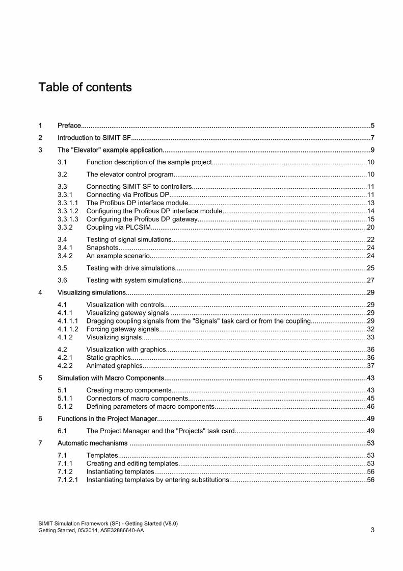
Table of contents
1 Preface.........................................................................................................................................................5
2 Introduction to SIMIT SF...............................................................................................................................7
3 The "Elevator" example application..............................................................................................................9 3.1 Function description of the sample project..................................................................................10 3.2 The elevator control program......................................................................................................10 3.3 Connecting SIMIT SF to controllers............................................................................................11 3.3.1 Connecting via Profibus DP........................................................................................................11 3.3.1.1 The Profibus DP interface module..............................................................................................13 3.3.1.2 Configuring the Profibus DP interface module............................................................................14 3.3.1.3 Configuring the Profibus DP gateway.........................................................................................15 3.3.2 Coupling via PLCSIM..................................................................................................................20 3.4 Testing of signal simulations.......................................................................................................22 3.4.1 Snapshots...................................................................................................................................24 3.4.2 An example scenario...................................................................................................................24 3.5 Testing with drive simulations.....................................................................................................25 3.6 Testing with system simulations..................................................................................................27
4 Visualizing simulations...............................................................................................................................29 4.1 Visualization with controls...........................................................................................................29 4.1.1 Visualizing gateway signals ........................................................................................................29 4.1.1.1 Dragging coupling signals from the "Signals" task card or from the coupling.............................29 4.1.1.2 Forcing gateway signals..............................................................................................................32 4.1.2 Visualizing signals.......................................................................................................................33 4.2 Visualization with graphics..........................................................................................................36 4.2.1 Static graphics.............................................................................................................................36 4.2.2 Animated graphics.......................................................................................................................37
5 Simulation with Macro Components...........................................................................................................43 5.1 Creating macro components.......................................................................................................43 5.1.1 Connectors of macro components..............................................................................................45 5.1.2 Defining parameters of macro components................................................................................46
6 Functions in the Project Manager...............................................................................................................49 6.1 The Project Manager and the "Projects" task card......................................................................49
7 Automatic mechanisms .............................................................................................................................53 7.1 Templates....................................................................................................................................53 7.1.1 Creating and editing templates....................................................................................................53 7.1.2 Instantiating templates................................................................................................................56 7.1.2.1 Instantiating templates by entering substitutions.........................................................................56
SIMIT Simulation Framework (SF) - Getting Started (V8.0)Getting Started, 05/2014, A5E32886640-AA 3

8 Find and Replace, Consistency Check.......................................................................................................63 8.1 Consistency check......................................................................................................................65
Table of contents
SIMIT Simulation Framework (SF) - Getting Started (V8.0)4 Getting Started, 05/2014, A5E32886640-AA
Preface 1Information about the SIMIT SF Getting Started
The Getting Started documentation uses an easy sample project to illustrate the basic principles and how the SIMIT SF software components interact during configuration and in simulation mode.
This Getting Started serves as an introduction and does not contain detailed or background information. Additional information is available in the online help on SIMIT SF and CTE (Component Type Editor).
If you want to use SIMIT SF in combination with PCS 7, we recommend reading the manual SIMIT Simulation Framework (SF) with PCS 7 - Getting Started.
Conventions
Note
In this documentation, the names of elements in the software interface are specified in the language of this documentation. If you have installed a multi-language package for the operating system, some of the designations will be displayed in the base language of the operating system after a language switch and will, therefore, differ from the designations used in the documentation.
In SIMIT SF, you can use standard Windows functions in many situations:
● Multiple selection using the "Ctrl" and "Shift" keys
● Column sorting in tables by clicking on the column header
● Use of "drag-and-drop" instead of "copy and paste"
The individual tutorials in the Getting Started build on one another. For this reason, you should work through all the tutorials in the specified sequence.
Purpose of this Getting Started documentationThis document aims to guide you quickly and successfully through the basics of SIMIT SF. You will get to know many basic configuration steps and develop an understanding for how SIMIT SF works.
Requirements for the SIMIT SF Getting StartedYou can run the sample projects "Elevator-01.simit", "Elevator-02.simit" and "Elevator-03.simit "on any computer on which the following software is installed:
● Windows 7 Professional or Ultimate SP1, 32-bit or 64-bit operating system
● SIMIT V8.0, PROFESSIONAL or ULTIMATE for use with a PLCSIM coupling, STANDARD for use with a PROFIBUS DP coupling
SIMIT Simulation Framework (SF) - Getting Started (V8.0)Getting Started, 05/2014, A5E32886640-AA 5

● SIMATIC STEP 7
● S7-PLCSIM V5.4 SP5
● Necessary license keys for the software listed above
Options for accessing documentation on SIMITYou can find the complete SIMIT documentation at the following locations:
● On the SIMIT V8.0 DVD
● on the Internet
● The product documentation is installed with the relevant product
Note
The statements in the SIMIT readme take precedence over all other SIMIT SF documentation.
Preface
SIMIT Simulation Framework (SF) - Getting Started (V8.0)6 Getting Started, 05/2014, A5E32886640-AA
Introduction to SIMIT SF 2
SIMIT SF can be used for the following applications:
● as convenient input and output of test signals for your controller
● as sophisticated plant simulator
In any situation SIMIT SF provides a cost-effective and easy way for testing and commissioning of automation software.
Even if you initially only use SIMIT SF as a convenient user interface for signal testing, you can add simulation models at any time later. This allows you to simulate your plant behavior and thus take full advantage of the capabilities of SIMIT SF by means of dynamic tests.
The following aspects are of particular interest when using SIMIT SF:
● CouplingYou can define the interface by which you wish to couple SIMIT SF to your automation system and specify the signals that you want to access in SIMIT SF.This means you can set and read signals now with SIMIT SF without any additional effort.
● SimulationYou do not need any expert knowledge in simulation in order to build a simulation. Just use the graphical user interface to combine existing components from the SIMIT libraries and enter the matching parameters.Components with a diverse set of simulation functions are available in the SIMIT basic library. These components cover a wide range of applications: from simple arithmetic and logical relationships to drive simulations and complex system simulations.Detailed descriptions of the library components and how to use them in diagrams can be found in the library manual. In the Sample Projects/Examples folder on your SIMIT software CD, you will find the archived SIMIT project Examples.simarc.. It contains examples of how to use library components.
● VisualizationYou can automatically generate diagrams with input and display elements (controls) from existing data, such as the data in the coupling, or manually build such diagrams individually.Graphic elements such as lines, rectangles, ellipses, etc. can be used both statically and animated with signals, and thus allow you to easily build comprehensive animations. Visualizations give you an overview of all signals in the plant. Values belonging to the same part of your system can also be shown in a grouped fashion, independent of the physical addresses they use.
The rest of this section just provides a basic understanding of how to use SIMIT SF.
You can start a simulation using the toolbar ( ), the menu bar (Simulation | Start) or by double-clicking Start ( ) in the project window. Once the simulation is running, the SIMIT SF color scheme changes from blue to orange.
While the simulation is running you may open and close any diagram or gateway. While a simulation is running you can select components on diagrams using the right mouse button.
SIMIT Simulation Framework (SF) - Getting Started (V8.0)Getting Started, 05/2014, A5E32886640-AA 7
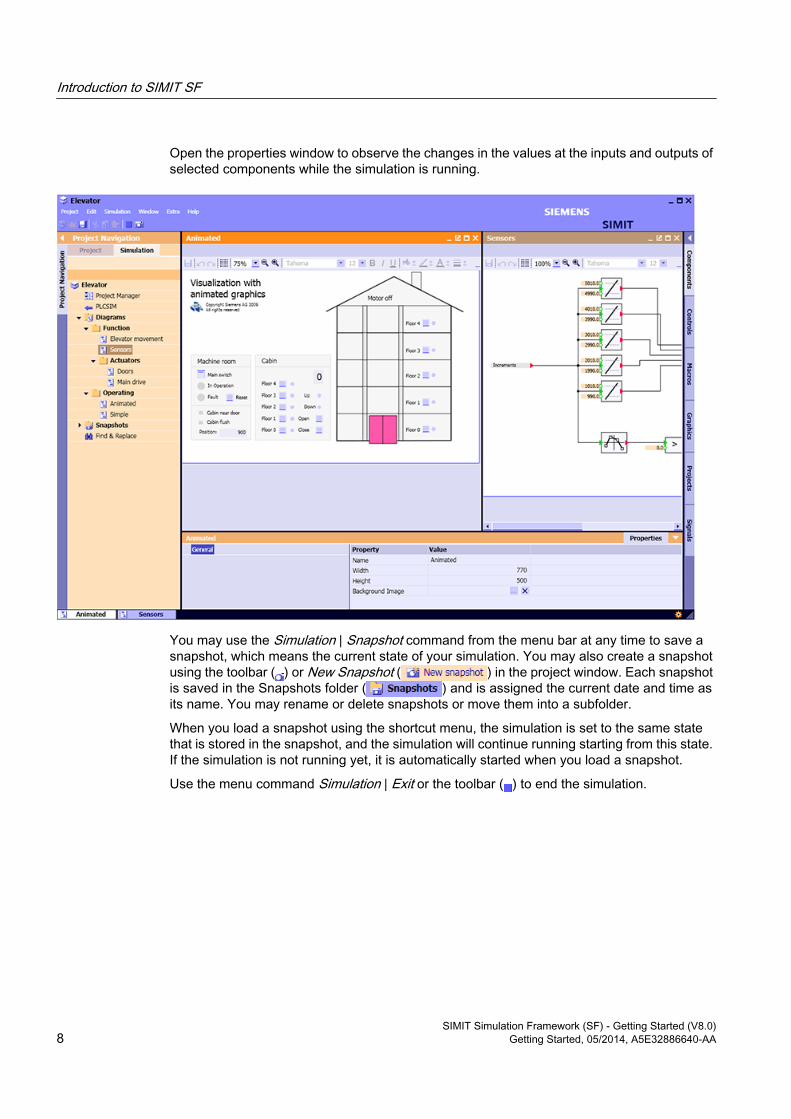
Open the properties window to observe the changes in the values at the inputs and outputs of selected components while the simulation is running.
You may use the Simulation | Snapshot command from the menu bar at any time to save a snapshot, which means the current state of your simulation. You may also create a snapshot using the toolbar ( ) or New Snapshot ( ) in the project window. Each snapshot is saved in the Snapshots folder ( ) and is assigned the current date and time as its name. You may rename or delete snapshots or move them into a subfolder.
When you load a snapshot using the shortcut menu, the simulation is set to the same state that is stored in the snapshot, and the simulation will continue running starting from this state. If the simulation is not running yet, it is automatically started when you load a snapshot.
Use the menu command Simulation | Exit or the toolbar ( ) to end the simulation.
Introduction to SIMIT SF
SIMIT Simulation Framework (SF) - Getting Started (V8.0)8 Getting Started, 05/2014, A5E32886640-AA
The "Elevator" example application 3
On the SIMIT software CD, in the Sample Projects\Elevator folder, you will find three archived projects Elevator-01.simarc, Elevator-02.simarc and Elevator-03.simarc. These simulation projects demonstrate various aspects of simulation-based testing with SIMIT SF. The PLC program to be tested with these simulation projects is an elevator control program. It is stored as an archived STEP 7 program Elevator_S7.zip on the SIMIT software CD in the same folder as the example projects. There you will also find the symbol table of the control program (Elevator.asc).
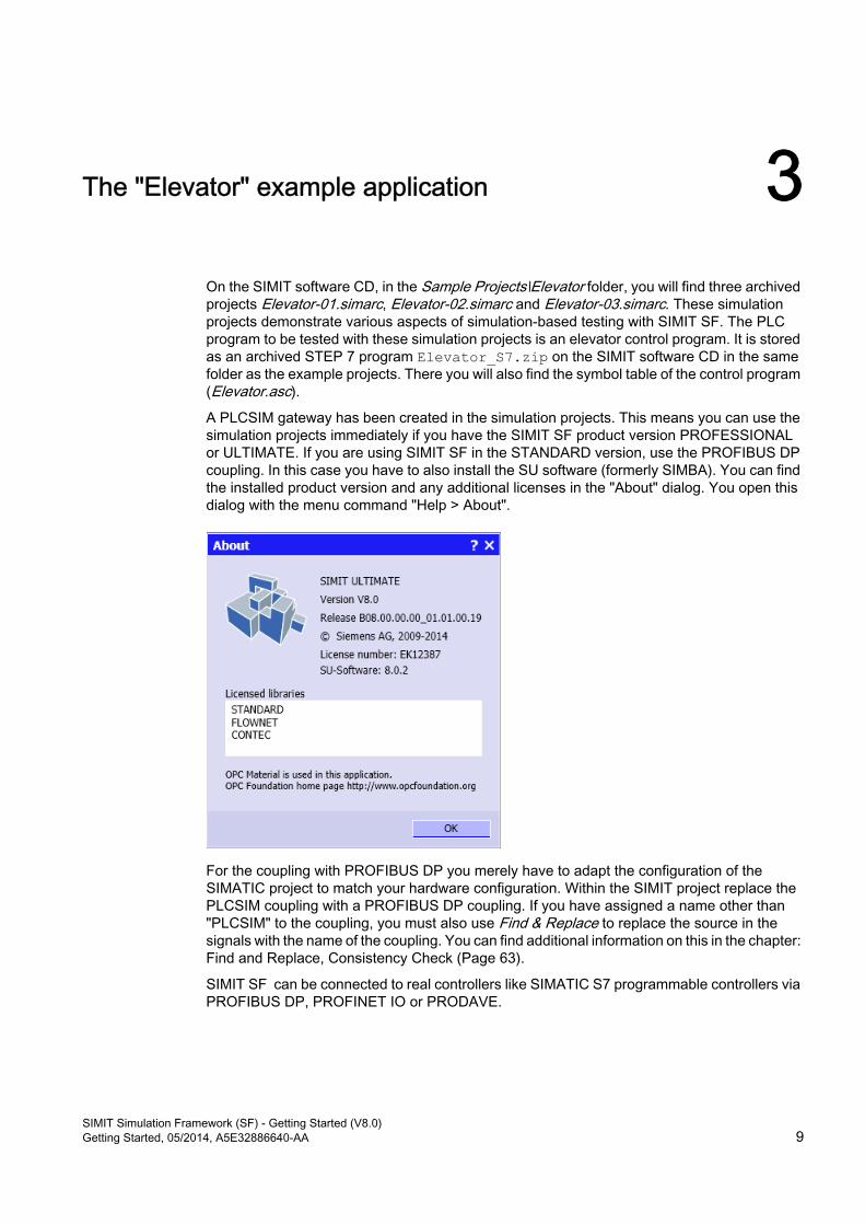
A PLCSIM gateway has been created in the simulation projects. This means you can use the simulation projects immediately if you have the SIMIT SF product version PROFESSIONAL or ULTIMATE. If you are using SIMIT SF in the STANDARD version, use the PROFIBUS DP coupling. In this case you have to also install the SU software (formerly SIMBA). You can find the installed product version and any additional licenses in the "About" dialog. You open this dialog with the menu command "Help > About".
For the coupling with PROFIBUS DP you merely have to adapt the configuration of the SIMATIC project to match your hardware configuration. Within the SIMIT project replace the PLCSIM coupling with a PROFIBUS DP coupling. If you have assigned a name other than "PLCSIM" to the coupling, you must also use Find & Replace to replace the source in the signals with the name of the coupling. You can find additional information on this in the chapter: Find and Replace, Consistency Check (Page 63).
SIMIT SF can be connected to real controllers like SIMATIC S7 programmable controllers via PROFIBUS DP, PROFINET IO or PRODAVE.
SIMIT Simulation Framework (SF) - Getting Started (V8.0)Getting Started, 05/2014, A5E32886640-AA 9
3.1 Function description of the sample projectThe example contains the simulation of an elevator that is located in a five-story building. On each floor there is a call button with feedback, which can be used to call the elevator.
Inside the elevator car the control panel can be used to select the destination floor. Furthermore there is a digital display on the control panel to indicate the elevator position (floor), and the elevator door can be opened or closed with a pushbutton on the control panel.
The elevator has a drive that can be operated at two speeds and in both directions. This drive has an encoder that can be used to retrieve the absolute position of the elevator (level counter) for use in the PLC.
For positioning the elevator car has a sensor in the door area to reduce the speed, and a sensor that detects that the elevator is flush with the opening for the door.
After connecting the main fuse the elevator control program will start working. Faults during operation of the elevator are indicated by a warning light. A pushbutton can be used to reset the system after a fault. After connection or after a reset the elevator moves to the ground floor and open its doors. After this the elevator is ready for regular operation.
3.2 The elevator control programThe elevator control program is built as a simple sequential state control program in STEP 7 with states as follows:
● WaitThe elevator control program remains in this state as long as there is no user request. The Wait state ends as soon as there is a request for another floor.
● Close doorIn this state the correct closing of the door is monitored. After closing the door the state is changed to Fast travel. When the pushbutton "Open Door" is pressed inside the elevator the state is changed to Open door.
● Fast travelThe elevator will move in the direction computed until a floor is reached that has a request. Once the elevator enters the door range the state changes to Slow travel.
● Slow travelThis state is used for precise positioning of the elevator on the floor. The state Open door is not entered until the elevator is flush with the door.
● Open doorIn this state the elevator door opens and the elevator state changes to Wait.
There is an additional Fault state in case of faults. When a fault in operation is detected, the state changes from any other state to the Fault state. After a reset the PLC enters the state Slow travel.The state diagram for this elevator control program is shown in the figure below.
The "Elevator" example application3.2 The elevator control program
SIMIT Simulation Framework (SF) - Getting Started (V8.0)10 Getting Started, 05/2014, A5E32886640-AA
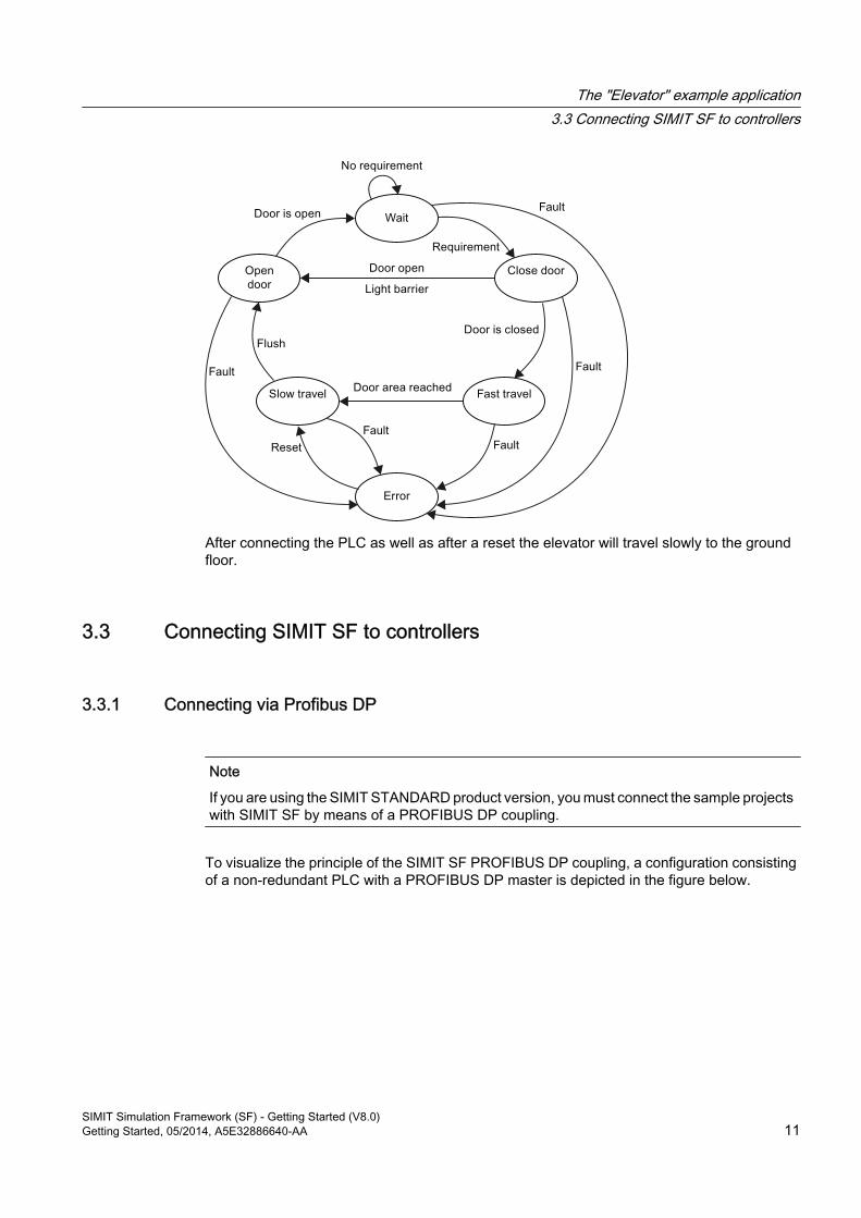
After connecting the PLC as well as after a reset the elevator will travel slowly to the ground floor.
3.3 Connecting SIMIT SF to controllers
3.3.1 Connecting via Profibus DP
Note
If you are using the SIMIT STANDARD product version, you must connect the sample projects with SIMIT SF by means of a PROFIBUS DP coupling.
To visualize the principle of the SIMIT SF PROFIBUS DP coupling, a configuration consisting of a non-redundant PLC with a PROFIBUS DP master is depicted in the figure below.
The "Elevator" example application3.3 Connecting SIMIT SF to controllers
SIMIT Simulation Framework (SF) - Getting Started (V8.0)Getting Started, 05/2014, A5E32886640-AA 11
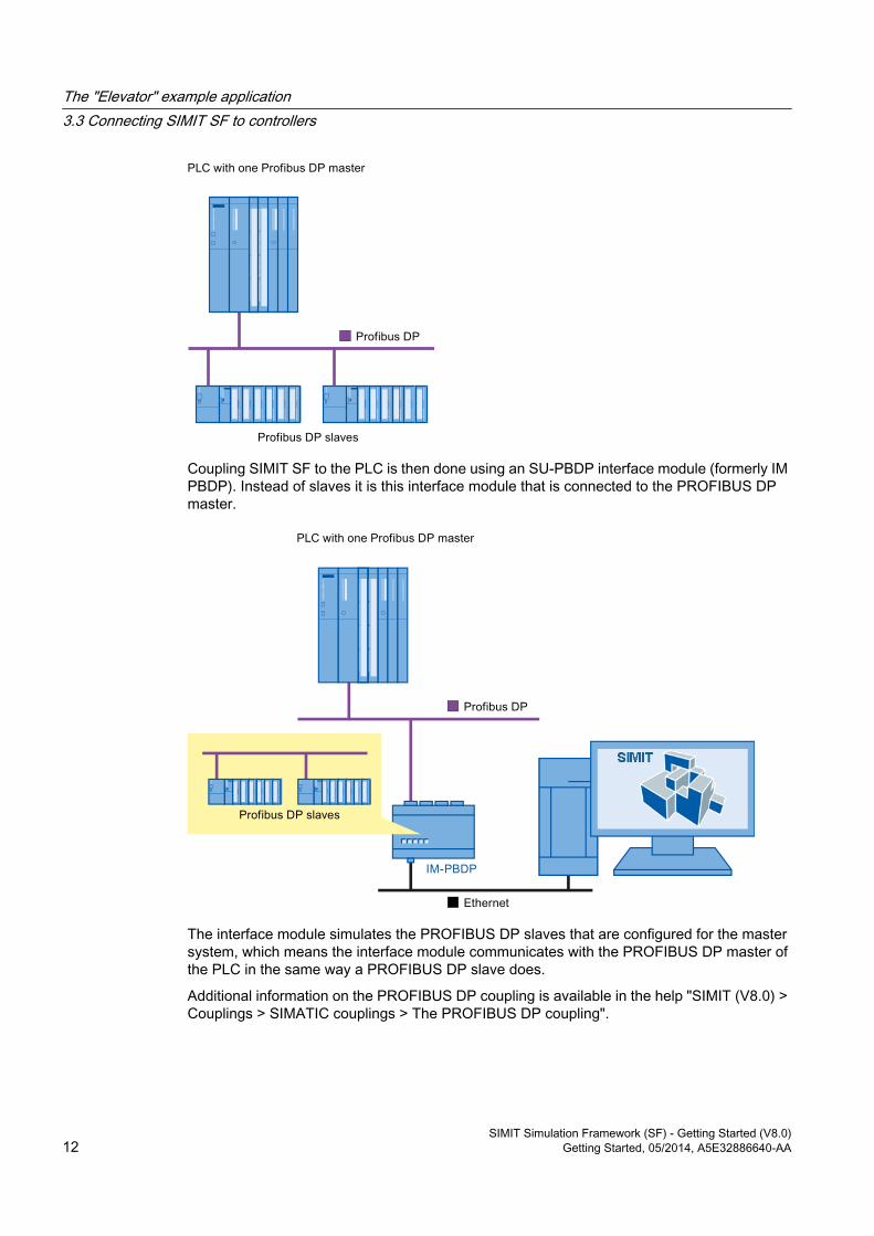
Coupling SIMIT SF to the PLC is then done using an SU-PBDP interface module (formerly IM PBDP). Instead of slaves it is this interface module that is connected to the PROFIBUS DP master.
The interface module simulates the PROFIBUS DP slaves that are configured for the master system, which means the interface module communicates with the PROFIBUS DP master of the PLC in the same way a PROFIBUS DP slave does.
Additional information on the PROFIBUS DP coupling is available in the help "SIMIT (V8.0) > Couplings > SIMATIC couplings > The PROFIBUS DP coupling".
The "Elevator" example application3.3 Connecting SIMIT SF to controllers
SIMIT Simulation Framework (SF) - Getting Started (V8.0)12 Getting Started, 05/2014, A5E32886640-AA
3.3.1.1 The Profibus DP interface moduleThe PROFIBUS DP interface module is available in several versions:
● SU-PBDP-2Two-channel interface module for simulating a maximum of 125 PROFIBUS slaves per channel.
● SU-PBDP-4Four-channel interface module for simulating a maximum of 125 PROFIBUS slaves per channel.
● SU-PBDP-8Eight-channel interface module for simulating a maximum of 125 PROFIBUS slaves per channel.
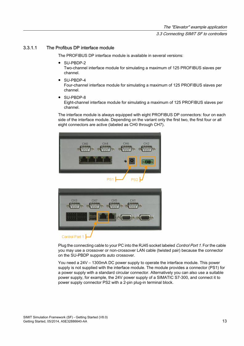
The interface module is always equipped with eight PROFIBUS DP connectors: four on each side of the interface module. Depending on the variant only the first two, the first four or all eight connectors are active (labeled as CH0 through CH7).
Plug the connecting cable to your PC into the RJ45 socket labeled Control Port 1. For the cable you may use a crossover or non-crossover LAN cable (twisted pair) because the connector on the SU-PBDP supports auto crossover.
You need a 24V – 1300mA DC power supply to operate the interface module. This power supply is not supplied with the interface module. The module provides a connector (PS1) for a power supply with a standard circular connector. Alternatively you can also use a suitable power supply, for example, the 24V power supply of a SIMATIC S7-300, and connect it to power supply connector PS2 with a 2-pin plug-in terminal block.
The "Elevator" example application3.3 Connecting SIMIT SF to controllers
SIMIT Simulation Framework (SF) - Getting Started (V8.0)Getting Started, 05/2014, A5E32886640-AA 13
3.3.1.2 Configuring the Profibus DP interface moduleTo access an SU-PBDP interface module with SIMIT SF via LAN you first need to assign a matching IP address to the interface module. To do so you need a PC with SIMATIC Manager installed and must – at least temporarily – connect the interface module to this PC. To configure the interface module it does not matter whether you are using a direct connection to the PC or a switch or hub.
● Configure the programming device / PC interface in SIMATIC Manager to use the LAN card to which the interface module is connected.
● Select PLC | Edit Ethernet node... from the menu in SIMATIC Manager.
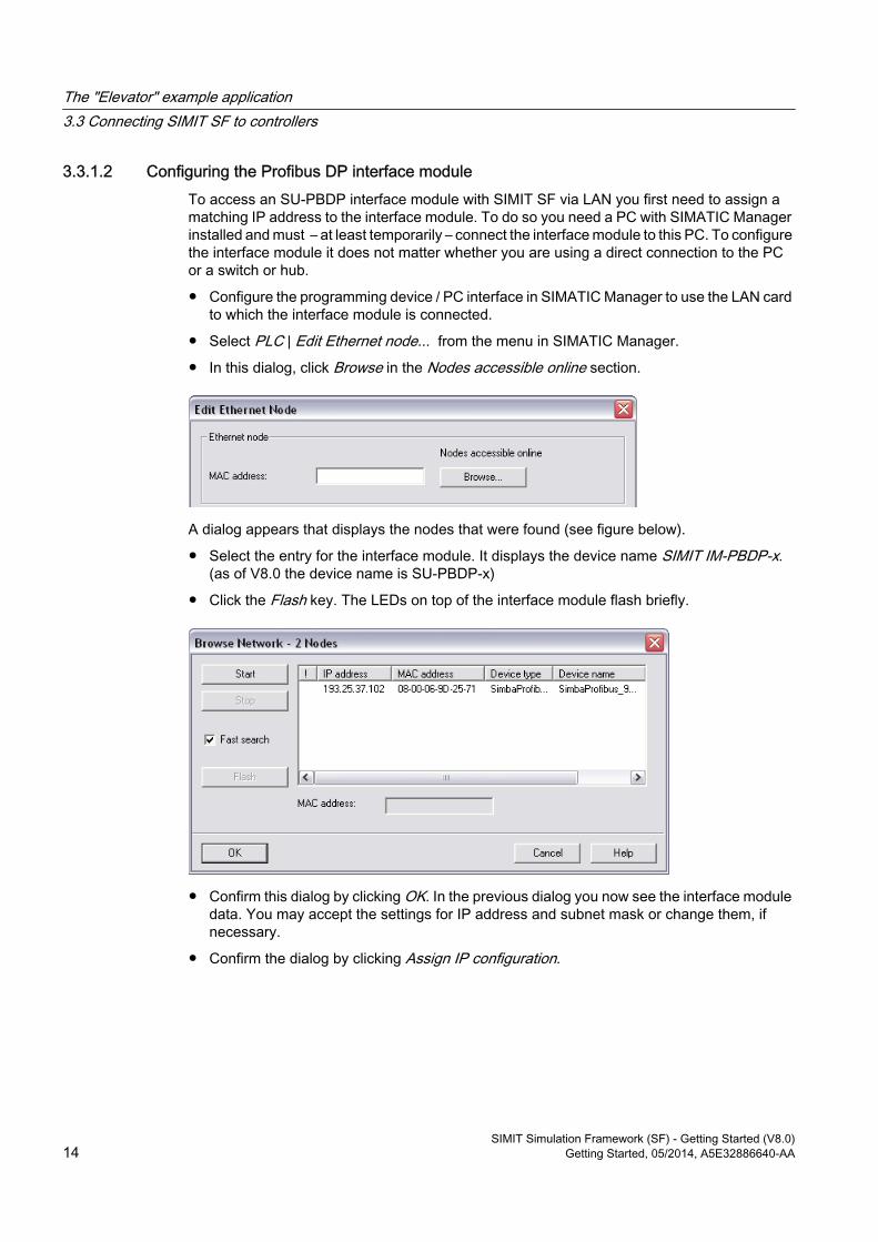
● In this dialog, click Browse in the Nodes accessible online section.
A dialog appears that displays the nodes that were found (see figure below).
● Select the entry for the interface module. It displays the device name SIMIT IM-PBDP-x. (as of V8.0 the device name is SU-PBDP-x)
● Click the Flash key. The LEDs on top of the interface module flash briefly.
● Confirm this dialog by clicking OK. In the previous dialog you now see the interface module data. You may accept the settings for IP address and subnet mask or change them, if necessary.
● Confirm the dialog by clicking Assign IP configuration.
The "Elevator" example application3.3 Connecting SIMIT SF to controllers
SIMIT Simulation Framework (SF) - Getting Started (V8.0)14 Getting Started, 05/2014, A5E32886640-AA
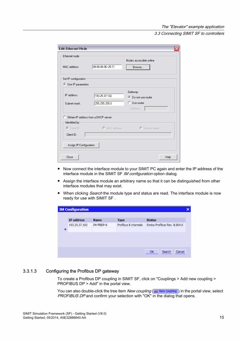
● Now connect the interface module to your SIMIT PC again and enter the IP address of the interface module in the SIMIT SF IM configuration option dialog.
● Assign the interface module an arbitrary name so that it can be distinguished from other interface modules that may exist.
● When clicking Search the module type and status are read. The interface module is now ready for use with SIMIT SF .
3.3.1.3 Configuring the Profibus DP gatewayTo create a Profibus DP coupling in SIMIT SF, click on "Couplings > Add new coupling > PROFIBUS DP > Add" in the portal view.
You can also double-click the tree item New coupling ( ) in the portal view, select PROFIBUS DP and confirm your selection with "OK" in the dialog that opens.
The "Elevator" example application3.3 Connecting SIMIT SF to controllers
SIMIT Simulation Framework (SF) - Getting Started (V8.0)Getting Started, 05/2014, A5E32886640-AA 15
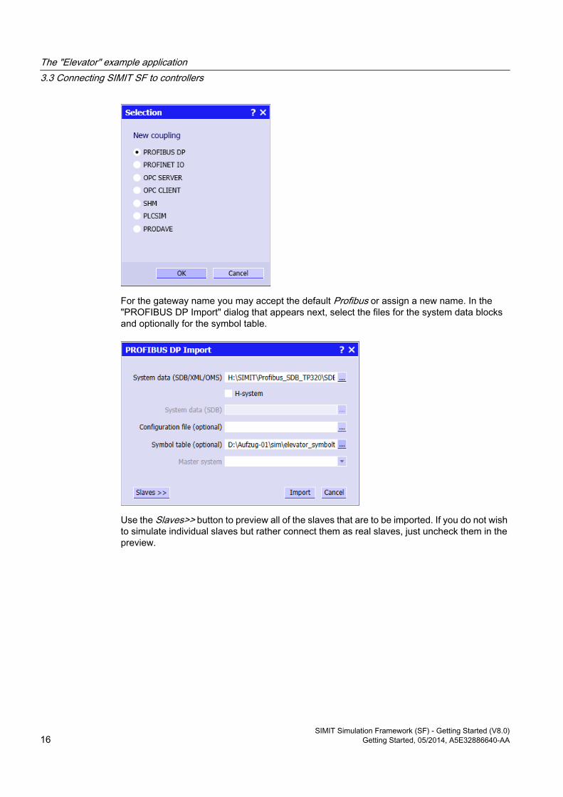
For the gateway name you may accept the default Profibus or assign a new name. In the "PROFIBUS DP Import" dialog that appears next, select the files for the system data blocks and optionally for the symbol table.
Use the Slaves>> button to preview all of the slaves that are to be imported. If you do not wish to simulate individual slaves but rather connect them as real slaves, just uncheck them in the preview.
The "Elevator" example application3.3 Connecting SIMIT SF to controllers
SIMIT Simulation Framework (SF) - Getting Started (V8.0)16 Getting Started, 05/2014, A5E32886640-AA
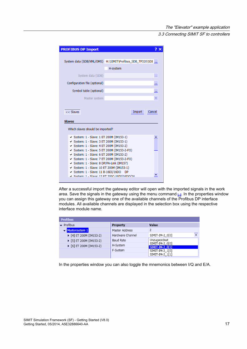
After a successful import the gateway editor will open with the imported signals in the work area. Save the signals in the gateway using the menu command . In the properties window you can assign this gateway one of the available channels of the Profibus DP interface modules. All available channels are displayed in the selection box using the respective interface module name.
In the properties window you can also toggle the mnemonics between I/Q and E/A.
The "Elevator" example application3.3 Connecting SIMIT SF to controllers
SIMIT Simulation Framework (SF) - Getting Started (V8.0)Getting Started, 05/2014, A5E32886640-AA 17
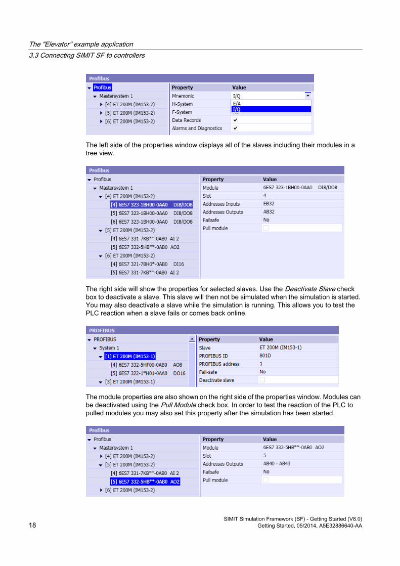
The left side of the properties window displays all of the slaves including their modules in a tree view.
The right side will show the properties for selected slaves. Use the Deactivate Slave check box to deactivate a slave. This slave will then not be simulated when the simulation is started. You may also deactivate a slave while the simulation is running. This allows you to test the PLC reaction when a slave fails or comes back online.
The module properties are also shown on the right side of the properties window. Modules can be deactivated using the Pull Module check box. In order to test the reaction of the PLC to pulled modules you may also set this property after the simulation has been started.
The "Elevator" example application3.3 Connecting SIMIT SF to controllers
SIMIT Simulation Framework (SF) - Getting Started (V8.0)18 Getting Started, 05/2014, A5E32886640-AA
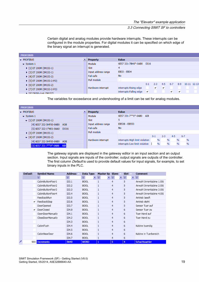
Certain digital and analog modules provide hardware interrupts. These interrupts can be configured in the module properties. For digital modules it can be specified on which edge of the binary signal an interrupt is generated.
The variables for exceedance and undershooting of a limit can be set for analog modules.
The gateway signals are displayed in the gateway editor in an input section and an output section. Input signals are inputs of the controller; output signals are outputs of the controller. The first column Default is used to provide default values for input signals, for example, to set binary inputs in the PLC.
The "Elevator" example application3.3 Connecting SIMIT SF to controllers
SIMIT Simulation Framework (SF) - Getting Started (V8.0)Getting Started, 05/2014, A5E32886640-AA 19
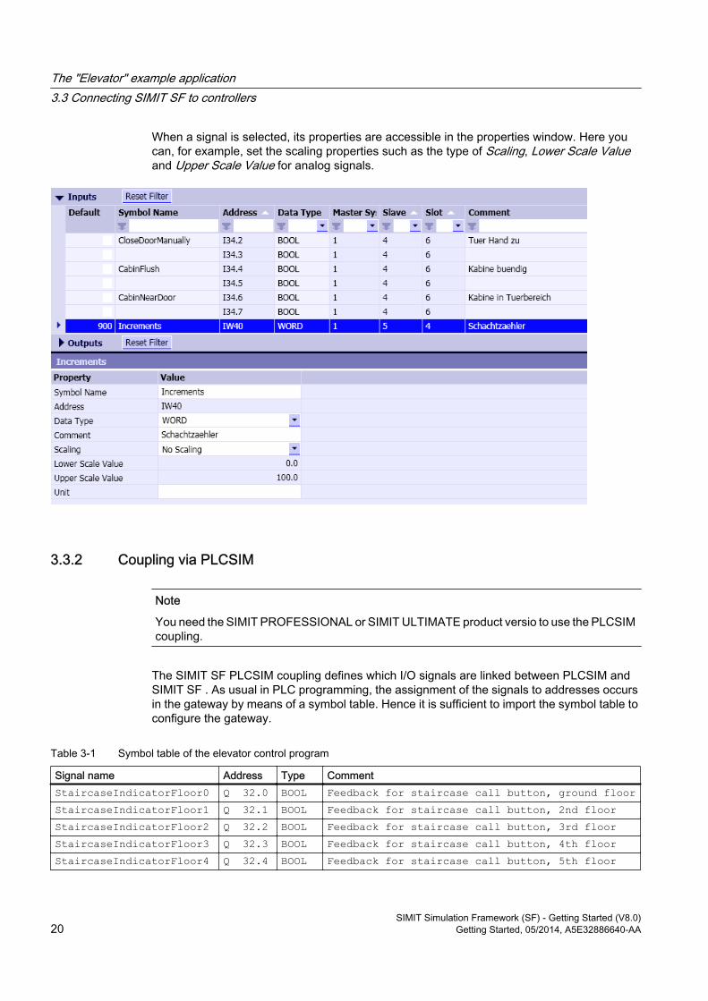
When a signal is selected, its properties are accessible in the properties window. Here you can, for example, set the scaling properties such as the type of Scaling, Lower Scale Value and Upper Scale Value for analog signals.
3.3.2 Coupling via PLCSIM
Note
You need the SIMIT PROFESSIONAL or SIMIT ULTIMATE product versio to use the PLCSIM coupling.
The SIMIT SF PLCSIM coupling defines which I/O signals are linked between PLCSIM and SIMIT SF . As usual in PLC programming, the assignment of the signals to addresses occurs in the gateway by means of a symbol table. Hence it is sufficient to import the symbol table to configure the gateway.
Table 3-1 Symbol table of the elevator control program
Signal name Address Type Comment StaircaseIndicatorFloor0 Q 32.0 BOOL Feedback for staircase call button, ground floorStaircaseIndicatorFloor1 Q 32.1 BOOL Feedback for staircase call button, 2nd floorStaircaseIndicatorFloor2 Q 32.2 BOOL Feedback for staircase call button, 3rd floorStaircaseIndicatorFloor3 Q 32.3 BOOL Feedback for staircase call button, 4th floorStaircaseIndicatorFloor4 Q 32.4 BOOL Feedback for staircase call button, 5th floor
The "Elevator" example application3.3 Connecting SIMIT SF to controllers
SIMIT Simulation Framework (SF) - Getting Started (V8.0)20 Getting Started, 05/2014, A5E32886640-AA
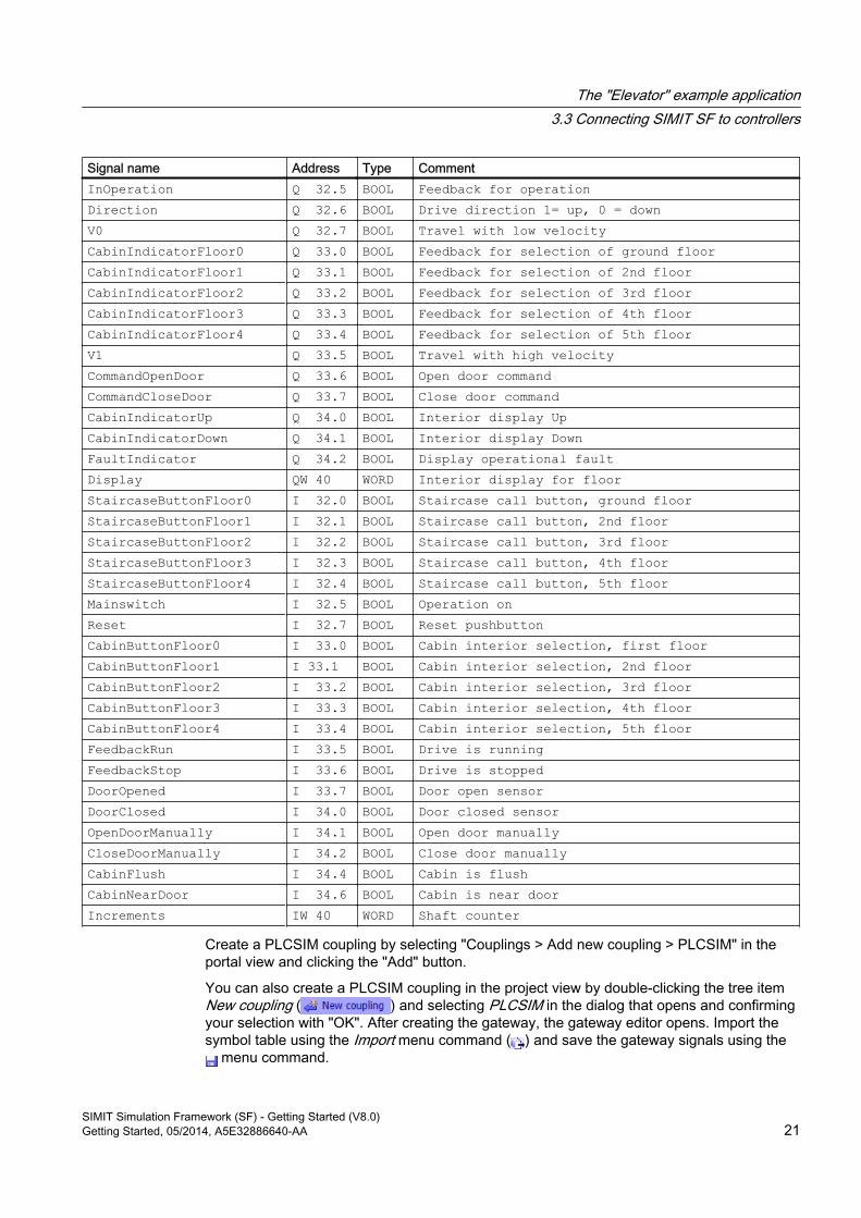
Signal name Address Type Comment InOperation Q 32.5 BOOL Feedback for operationDirection Q 32.6 BOOL Drive direction 1= up, 0 = downV0 Q 32.7 BOOL Travel with low velocityCabinIndicatorFloor0 Q 33.0 BOOL Feedback for selection of ground floorCabinIndicatorFloor1 Q 33.1 BOOL Feedback for selection of 2nd floorCabinIndicatorFloor2 Q 33.2 BOOL Feedback for selection of 3rd floorCabinIndicatorFloor3 Q 33.3 BOOL Feedback for selection of 4th floorCabinIndicatorFloor4 Q 33.4 BOOL Feedback for selection of 5th floorV1 Q 33.5 BOOL Travel with high velocityCommandOpenDoor Q 33.6 BOOL Open door commandCommandCloseDoor Q 33.7 BOOL Close door commandCabinIndicatorUp Q 34.0 BOOL Interior display UpCabinIndicatorDown Q 34.1 BOOL Interior display DownFaultIndicator Q 34.2 BOOL Display operational faultDisplay QW 40 WORD Interior display for floorStaircaseButtonFloor0 I 32.0 BOOL Staircase call button, ground floorStaircaseButtonFloor1 I 32.1 BOOL Staircase call button, 2nd floorStaircaseButtonFloor2 I 32.2 BOOL Staircase call button, 3rd floorStaircaseButtonFloor3 I 32.3 BOOL Staircase call button, 4th floorStaircaseButtonFloor4 I 32.4 BOOL Staircase call button, 5th floorMainswitch I 32.5 BOOL Operation onReset I 32.7 BOOL Reset pushbuttonCabinButtonFloor0 I 33.0 BOOL Cabin interior selection, first floorCabinButtonFloor1 I 33.1 BOOL Cabin interior selection, 2nd floorCabinButtonFloor2 I 33.2 BOOL Cabin interior selection, 3rd floorCabinButtonFloor3 I 33.3 BOOL Cabin interior selection, 4th floorCabinButtonFloor4 I 33.4 BOOL Cabin interior selection, 5th floorFeedbackRun I 33.5 BOOL Drive is runningFeedbackStop I 33.6 BOOL Drive is stoppedDoorOpened I 33.7 BOOL Door open sensorDoorClosed I 34.0 BOOL Door closed sensorOpenDoorManually I 34.1 BOOL Open door manuallyCloseDoorManually I 34.2 BOOL Close door manuallyCabinFlush I 34.4 BOOL Cabin is flushCabinNearDoor I 34.6 BOOL Cabin is near doorIncrements IW 40 WORD Shaft counter
Create a PLCSIM coupling by selecting "Couplings > Add new coupling > PLCSIM" in the portal view and clicking the "Add" button.
You can also create a PLCSIM coupling in the project view by double-clicking the tree item New coupling ( ) and selecting PLCSIM in the dialog that opens and confirming your selection with "OK". After creating the gateway, the gateway editor opens. Import the symbol table using the Import menu command ( ) and save the gateway signals using the
menu command.
The "Elevator" example application3.3 Connecting SIMIT SF to controllers
SIMIT Simulation Framework (SF) - Getting Started (V8.0)Getting Started, 05/2014, A5E32886640-AA 21
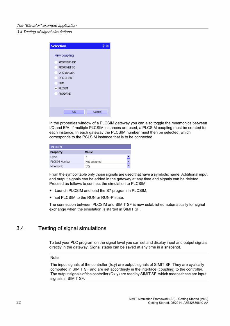
In the properties window of a PLCSIM gateway you can also toggle the mnemonics between I/Q and E/A. If multiple PLCSIM instances are used, a PLCSIM coupling must be created for each instance. In each gateway the PLCSIM number must then be selected, which corresponds to the PCLSIM instance that is to be connected.
From the symbol table only those signals are used that have a symbolic name. Additional input and output signals can be added in the gateway at any time and signals can be deleted. Proceed as follows to connect the simulation to PLCSIM:
● Launch PLCSIM and load the S7 program in PLCSIM,
● set PLCSIM to the RUN or RUN-P state.
The connection between PLCSIM and SIMIT SF is now established automatically for signal exchange when the simulation is started in SIMIT SF.
3.4 Testing of signal simulations
To test your PLC program on the signal level you can set and display input and output signals directly in the gateway. Signal states can be saved at any time in a snapshot.
Note
The input signals of the controller (Ix.y) are output signals of SIMIT SF. They are cyclically computed in SIMIT SF and are set accordingly in the interface (coupling) to the controller. The output signals of the controller (Qx.y) are read by SIMIT SF, which means these are input signals in SIMIT SF.
The "Elevator" example application3.4 Testing of signal simulations
SIMIT Simulation Framework (SF) - Getting Started (V8.0)22 Getting Started, 05/2014, A5E32886640-AA
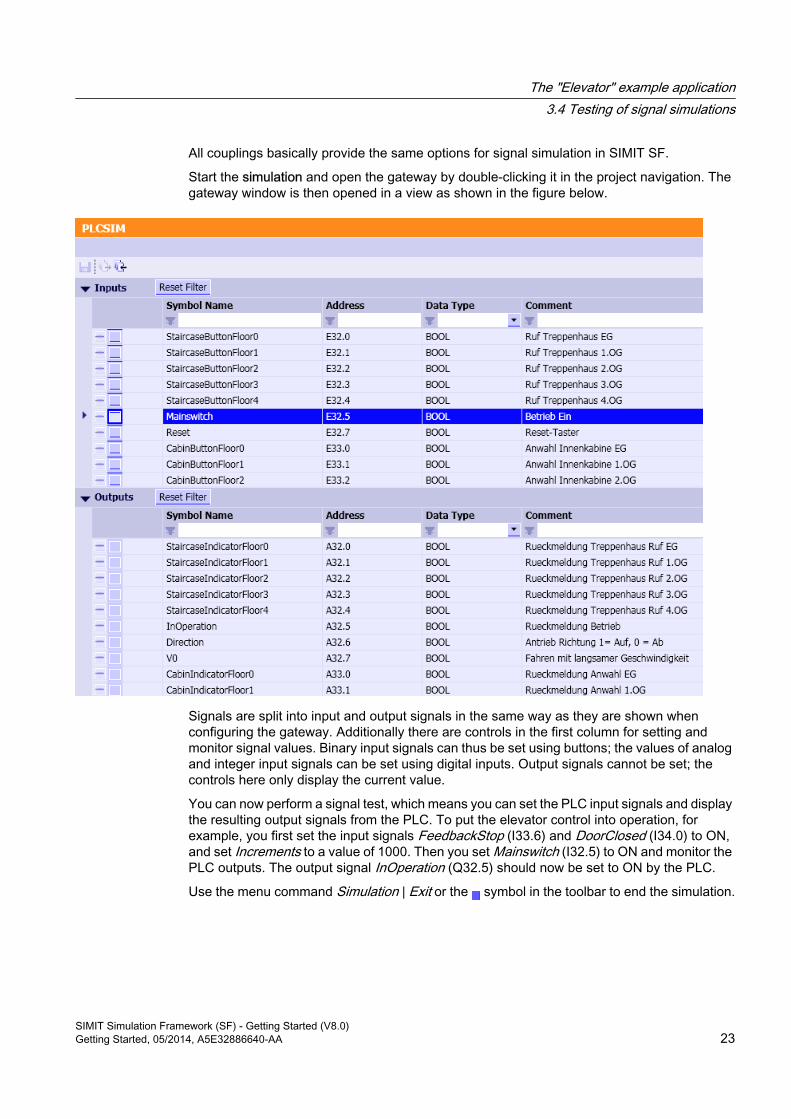
All couplings basically provide the same options for signal simulation in SIMIT SF.
Start the simulation and open the gateway by double-clicking it in the project navigation. The gateway window is then opened in a view as shown in the figure below.
Signals are split into input and output signals in the same way as they are shown when configuring the gateway. Additionally there are controls in the first column for setting and monitor signal values. Binary input signals can thus be set using buttons; the values of analog and integer input signals can be set using digital inputs. Output signals cannot be set; the controls here only display the current value.
You can now perform a signal test, which means you can set the PLC input signals and display the resulting output signals from the PLC. To put the elevator control into operation, for example, you first set the input signals FeedbackStop (I33.6) and DoorClosed (I34.0) to ON, and set Increments to a value of 1000. Then you set Mainswitch (I32.5) to ON and monitor the PLC outputs. The output signal InOperation (Q32.5) should now be set to ON by the PLC.
Use the menu command Simulation | Exit or the symbol in the toolbar to end the simulation.
The "Elevator" example application3.4 Testing of signal simulations
SIMIT Simulation Framework (SF) - Getting Started (V8.0)Getting Started, 05/2014, A5E32886640-AA 23
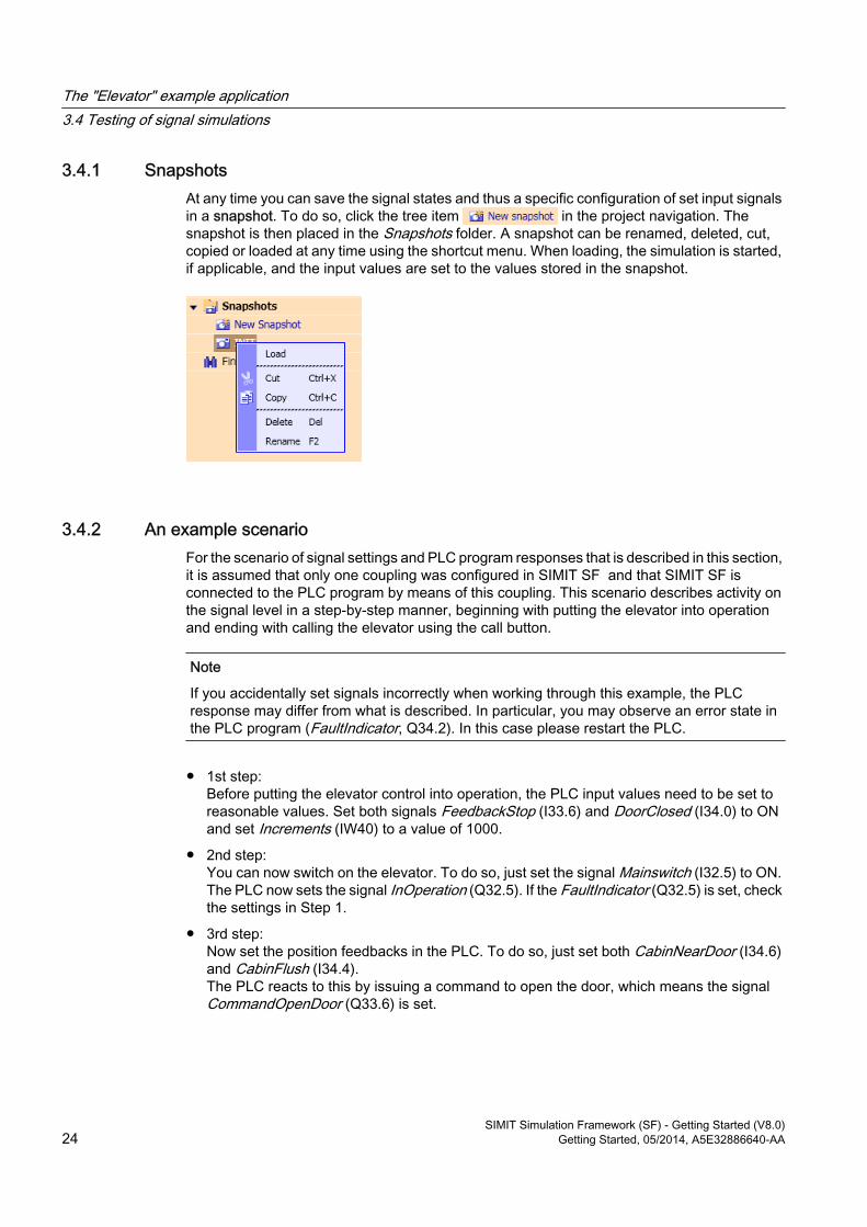
3.4.1 SnapshotsAt any time you can save the signal states and thus a specific configuration of set input signals in a snapshot. To do so, click the tree item in the project navigation. The snapshot is then placed in the Snapshots folder. A snapshot can be renamed, deleted, cut, copied or loaded at any time using the shortcut menu. When loading, the simulation is started, if applicable, and the input values are set to the values stored in the snapshot.
3.4.2 An example scenarioFor the scenario of signal settings and PLC program responses that is described in this section, it is assumed that only one coupling was configured in SIMIT SF and that SIMIT SF is connected to the PLC program by means of this coupling. This scenario describes activity on the signal level in a step-by-step manner, beginning with putting the elevator into operation and ending with calling the elevator using the call button.
Note
If you accidentally set signals incorrectly when working through this example, the PLC response may differ from what is described. In particular, you may observe an error state in the PLC program (FaultIndicator, Q34.2). In this case please restart the PLC.
● 1st step:Before putting the elevator control into operation, the PLC input values need to be set to reasonable values. Set both signals FeedbackStop (I33.6) and DoorClosed (I34.0) to ON and set Increments (IW40) to a value of 1000.
● 2nd step:You can now switch on the elevator. To do so, just set the signal Mainswitch (I32.5) to ON. The PLC now sets the signal InOperation (Q32.5). If the FaultIndicator (Q32.5) is set, check the settings in Step 1.
● 3rd step:Now set the position feedbacks in the PLC. To do so, just set both CabinNearDoor (I34.6) and CabinFlush (I34.4).The PLC reacts to this by issuing a command to open the door, which means the signal CommandOpenDoor (Q33.6) is set.
The "Elevator" example application3.4 Testing of signal simulations
SIMIT Simulation Framework (SF) - Getting Started (V8.0)24 Getting Started, 05/2014, A5E32886640-AA
● 4th step:Now open the door by setting DoorOpened (I1.7) to ON and DoorClosed (I2.0) to OFF.You will notice that the PLC cancels the command to open the door, which means the signal CommandOpenDoor is reset.
● 5th step:You can now move the elevator. To do this place a call for the second floor by setting the input signal CabinButtonFloor1 (I33.1) to ON. The PLC now issues a command to close the door and set the signal CommandCloseDoor (Q33.7).
● 6th step:Close the door by setting DoorOpened (I1.7) to OFF and DoorClosed (I2.0) to ON.The PLC sets the drive to fast travel, which means the signal V1 (Q33.5) is set.
● 7th step:Now set the drive feedback in the PLC as follows: Set FeedbackStop (I33.6) to OFF and FeedbackRun (I33.5) to ON.
The PLC has now detected a fault – the fault indicator (signal I43.2) lights up. What happened? Let us review the last step: In order to set the drive feedback, you first set FeedbackStop to OFF and then set FeedbackRun to ON or vice versa. In the first case there was a brief moment between setting the two signals when neither of the feedbacks was set, and in the latter case the feedbacks were momentarily both set. In both cases the drive's exclusive OR monitoring was activated at this moment in the PLC and decided that there was a malfunction. FeedbackRun and FeedbackStop may not both be set to ON or OFF at the same time. This case is interpreted as a faulty drive by the PLC.
3.5 Testing with drive simulationsUnless the PLC program is changed, the PLC reaction as described in the preceding section limits signal testing to the steps described above. The reason is that it is virtually impossible to simultaneously toggle two signals manually. For such cases, SIMIT provides the option of using drive simulations. Not only can you set signals simultaneously but you are also able to simulate the dynamic behavior of the drive. The sample project Elevator-01.simarc includes simulations of the drives for the elevator control.
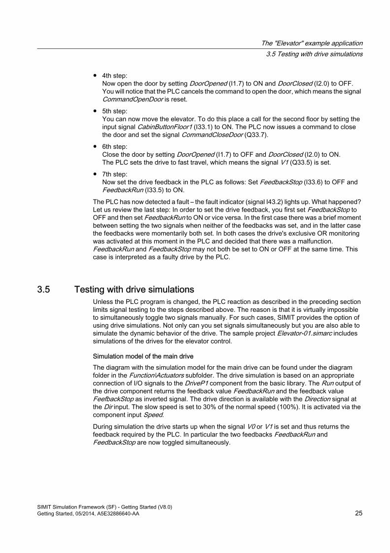
Simulation model of the main driveThe diagram with the simulation model for the main drive can be found under the diagram folder in the Function\Actuators subfolder. The drive simulation is based on an appropriate connection of I/O signals to the DriveP1 component from the basic library. The Run output of the drive component returns the feedback value FeedbackRun and the feedback value FeefbackStop as inverted signal. The drive direction is available with the Direction signal at the Dir input. The slow speed is set to 30% of the normal speed (100%). It is activated via the component input Speed.
During simulation the drive starts up when the signal V0 or V1 is set and thus returns the feedback required by the PLC. In particular the two feedbacks FeedbackRun and FeedbackStop are now toggled simultaneously.
The "Elevator" example application3.5 Testing with drive simulations
SIMIT Simulation Framework (SF) - Getting Started (V8.0)Getting Started, 05/2014, A5E32886640-AA 25
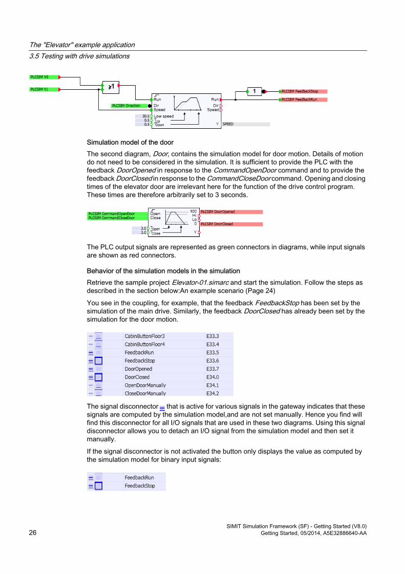
Simulation model of the doorThe second diagram, Door, contains the simulation model for door motion. Details of motion do not need to be considered in the simulation. It is sufficient to provide the PLC with the feedback DoorOpened in response to the CommandOpenDoor command and to provide the feedback DoorClosed in response to the CommandCloseDoor command. Opening and closing times of the elevator door are irrelevant here for the function of the drive control program. These times are therefore arbitrarily set to 3 seconds.
The PLC output signals are represented as green connectors in diagrams, while input signals are shown as red connectors.
Behavior of the simulation models in the simulationRetrieve the sample project Elevator-01.simarc and start the simulation. Follow the steps as described in the section below:An example scenario (Page 24)
You see in the coupling, for example, that the feedback FeedbackStop has been set by the simulation of the main drive. Similarly, the feedback DoorClosed has already been set by the simulation for the door motion.
The signal disconnector that is active for various signals in the gateway indicates that these signals are computed by the simulation model,and are not set manually. Hence you find will find this disconnector for all I/O signals that are used in these two diagrams. Using this signal disconnector allows you to detach an I/O signal from the simulation model and then set it manually.
If the signal disconnector is not activated the button only displays the value as computed by the simulation model for binary input signals:
The "Elevator" example application3.5 Testing with drive simulations
SIMIT Simulation Framework (SF) - Getting Started (V8.0)26 Getting Started, 05/2014, A5E32886640-AA
The switch on the right-hand side is initially not operable, which means the button cannot be pressed. The input signal cannot be set manually with the switch on the right-hand side until the signal disconnector is activated ( ):
All you have to do in the first step now is to set the input signal Increments (IW512) to 1000 and switch on the main switch in the second step, which means set the signal Mainswitch (I32.5) to ON.
When you set both of the controller position indicators CabinNearDoor (I34.6) and CabinFlush (I34.4) to ON you see that feedback DoorClosed (I34.0) is set to OFF and that feedback DoorOpened (I33.7) is set to ON after a few seconds. The elevator door simulation now accepts the setting of both sensor feedbacks.
This means both feedbacks FeedbackRun and FeedbackStop are set by the simulation of the main drive. Both feedbacks indicate that the drive is turned off at first. After activating the drive by means of a call such as CabinButtonFloor1, feedbacks are now switched by the main drive simulation. Please note that in a real elevator system the signal CabinButtonFloor1 is set by a pushbutton so you need to switch it off as soon as the PLC has recognized the call.
This makes it much easier to run the scenario. You need to set fewer signals manually because the simulation of the drive and the door motion generate appropriate feedback.
3.6 Testing with system simulationsAn even greater reduction in the effort required for testing the PLC program can be achieved by not only simulating the drives, but in the case of the elevator considered here, by also simulating the motion of the elevator cabin using the resulting sensor signals. For this purpose, the project Elevator-02 contains a simulation model that includes simulations of the elevator motion and of the cabin sensors in addition to the drive simulations.
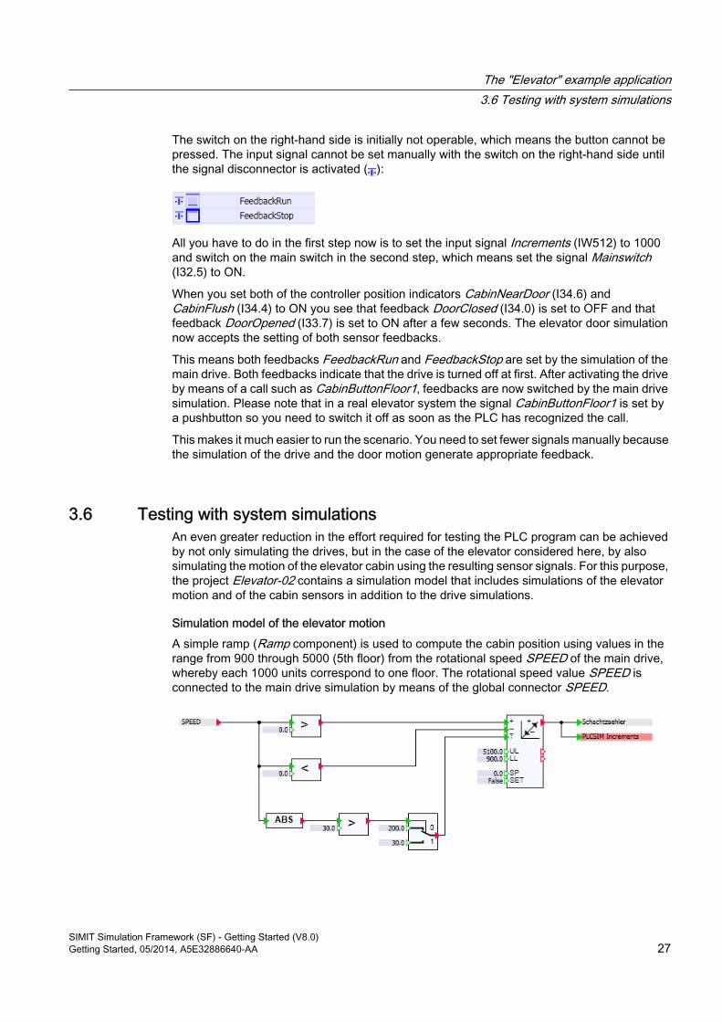
Simulation model of the elevator motionA simple ramp (Ramp component) is used to compute the cabin position using values in the range from 900 through 5000 (5th floor) from the rotational speed SPEED of the main drive, whereby each 1000 units correspond to one floor. The rotational speed value SPEED is connected to the main drive simulation by means of the global connector SPEED.
The "Elevator" example application3.6 Testing with system simulations
SIMIT Simulation Framework (SF) - Getting Started (V8.0)Getting Started, 05/2014, A5E32886640-AA 27
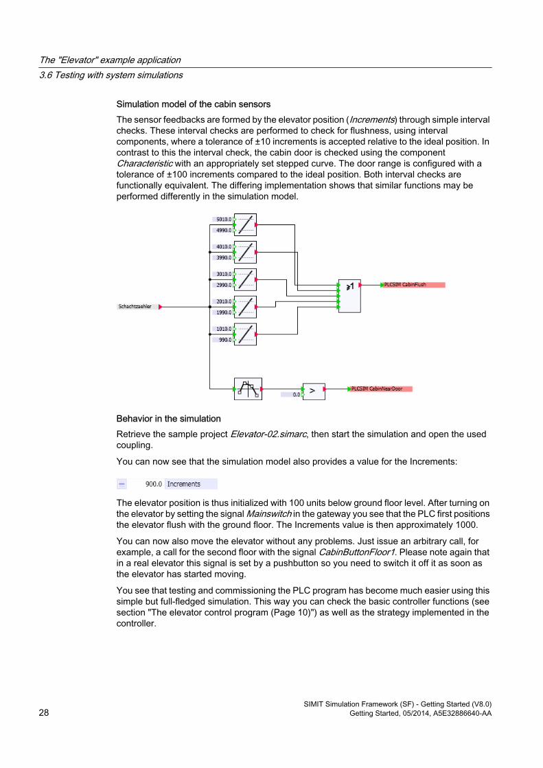
Simulation model of the cabin sensorsThe sensor feedbacks are formed by the elevator position (Increments) through simple interval checks. These interval checks are performed to check for flushness, using interval components, where a tolerance of ±10 increments is accepted relative to the ideal position. In contrast to this the interval check, the cabin door is checked using the component Characteristic with an appropriately set stepped curve. The door range is configured with a tolerance of ±100 increments compared to the ideal position. Both interval checks are functionally equivalent. The differing implementation shows that similar functions may be performed differently in the simulation model.
Behavior in the simulationRetrieve the sample project Elevator-02.simarc, then start the simulation and open the used coupling.You can now see that the simulation model also provides a value for the Increments:
The elevator position is thus initialized with 100 units below ground floor level. After turning on the elevator by setting the signal Mainswitch in the gateway you see that the PLC first positions the elevator flush with the ground floor. The Increments value is then approximately 1000.
You can now also move the elevator without any problems. Just issue an arbitrary call, for example, a call for the second floor with the signal CabinButtonFloor1. Please note again that in a real elevator this signal is set by a pushbutton so you need to switch it off it as soon as the elevator has started moving.
You see that testing and commissioning the PLC program has become much easier using this simple but full-fledged simulation. This way you can check the basic controller functions (see section "The elevator control program (Page 10)") as well as the strategy implemented in the controller.
The "Elevator" example application3.6 Testing with system simulations
SIMIT Simulation Framework (SF) - Getting Started (V8.0)28 Getting Started, 05/2014, A5E32886640-AA
Visualizing simulations 4
SIMIT SF allows you to use graphic functions to vividly display events within the plant simulation and to manually intervene in the simulation. A simple approach for visualizing simulations is to drag and drop I/O signals from the gateway onto diagrams. Controls, which means operating and display controls from the standard library, provide access to all signals within the simulation. Static graphics may be used to design more informative simulations. Animated graphics allow you to visualize motions within the simulated system.
The section below shows various approaches using the visualization of the elevator model as an example. The diagrams that are used for this purpose can be found in the simulation project Elevator-03.
4.1 Visualization with controls
4.1.1 Visualizing gateway signals
4.1.1.1 Dragging coupling signals from the "Signals" task card or from the couplingSIMIT SF allows you to arrange controls on charts and use these controls to display and set signals. You can thus assemble controls on various charts in arbitrary groupings. For each chart, you can specify not only the signals that are displayed but also their arrangement.
When a simulation is running, a control with a signal splitter is provided for each signal in the coupling. This control along with its associated signal splitter can also be placed on charts for any coupling signal. To do so, simply drag and drop the signal from the coupling onto the diagram. You may drag the signal either from the coupling or from the signal task card.
Dragging gateway signals from a gatewayTo drag a signal from a gateway onto a diagram you must open both the gateway and the diagram in the working area.
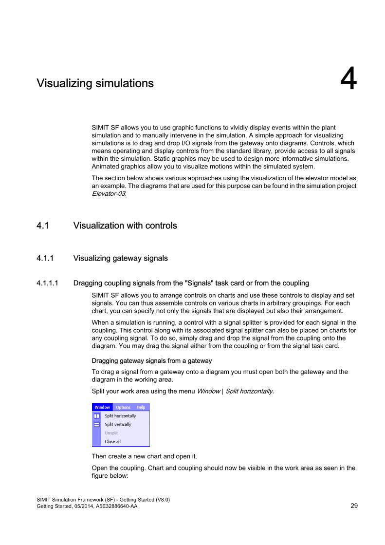
Split your work area using the menu Window | Split horizontally.
Then create a new chart and open it.
Open the coupling. Chart and coupling should now be visible in the work area as seen in the figure below:
SIMIT Simulation Framework (SF) - Getting Started (V8.0)Getting Started, 05/2014, A5E32886640-AA 29
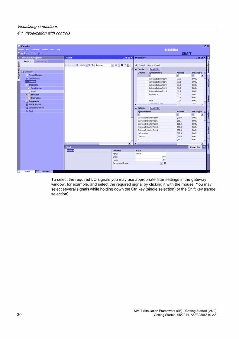
To select the required I/O signals you may use appropriate filter settings in the gateway window, for example, and select the required signal by clicking it with the mouse. You may select several signals while holding down the Ctrl key (single selection) or the Shift key (range selection).
Visualizing simulations4.1 Visualization with controls
SIMIT Simulation Framework (SF) - Getting Started (V8.0)30 Getting Started, 05/2014, A5E32886640-AA
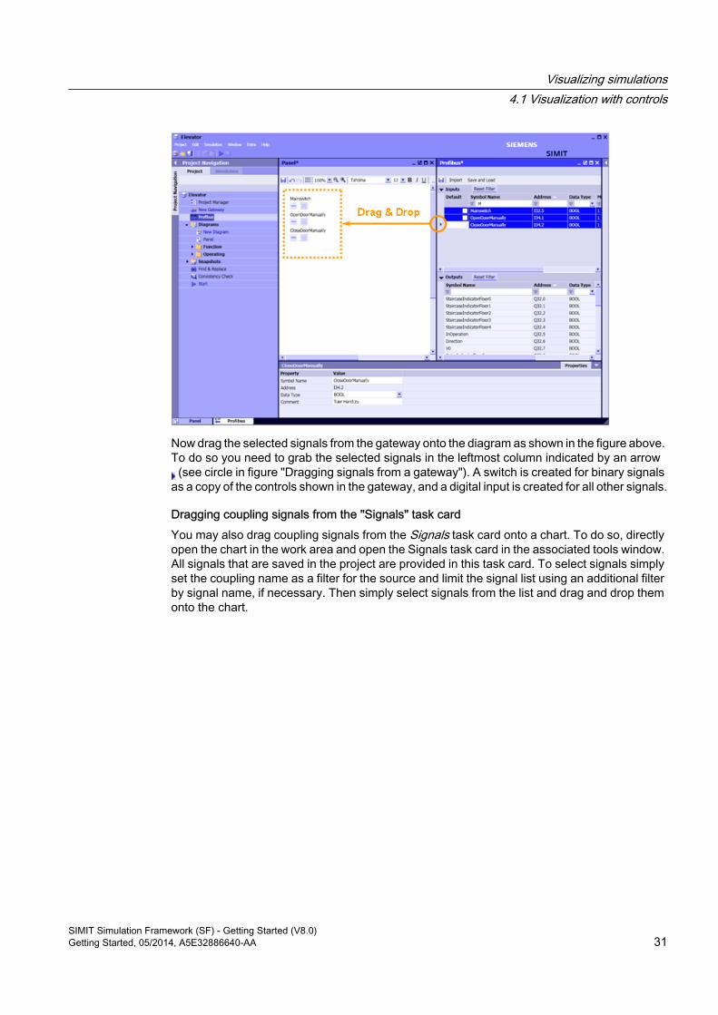
Now drag the selected signals from the gateway onto the diagram as shown in the figure above. To do so you need to grab the selected signals in the leftmost column indicated by an arrow (see circle in figure "Dragging signals from a gateway"). A switch is created for binary signals
as a copy of the controls shown in the gateway, and a digital input is created for all other signals.
Dragging coupling signals from the "Signals" task cardYou may also drag coupling signals from the Signals task card onto a chart. To do so, directly open the chart in the work area and open the Signals task card in the associated tools window. All signals that are saved in the project are provided in this task card. To select signals simply set the coupling name as a filter for the source and limit the signal list using an additional filter by signal name, if necessary. Then simply select signals from the list and drag and drop them onto the chart.
Visualizing simulations4.1 Visualization with controls
SIMIT Simulation Framework (SF) - Getting Started (V8.0)Getting Started, 05/2014, A5E32886640-AA 31
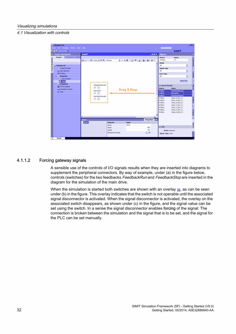
4.1.1.2 Forcing gateway signalsA sensible use of the controls of I/O signals results when they are inserted into diagrams to supplement the peripheral connectors. By way of example, under (a) in the figure below, controls (switches) for the two feedbacks FeedbackRun and FeedbackStop are inserted in the diagram for the simulation of the main drive.
When the simulation is started both switches are shown with an overlay , as can be seen under (b) in the figure. This overlay indicates that the switch is not operable until the associated signal disconnector is activated. When the signal disconnector is activated, the overlay on the associated switch disappears, as shown under (c) in the figure, and the signal value can be set using the switch. In a sense the signal disconnector enables forcing of the signal: The connection is broken between the simulation and the signal that is to be set, and the signal for the PLC can be set manually.
Visualizing simulations4.1 Visualization with controls
SIMIT Simulation Framework (SF) - Getting Started (V8.0)32 Getting Started, 05/2014, A5E32886640-AA
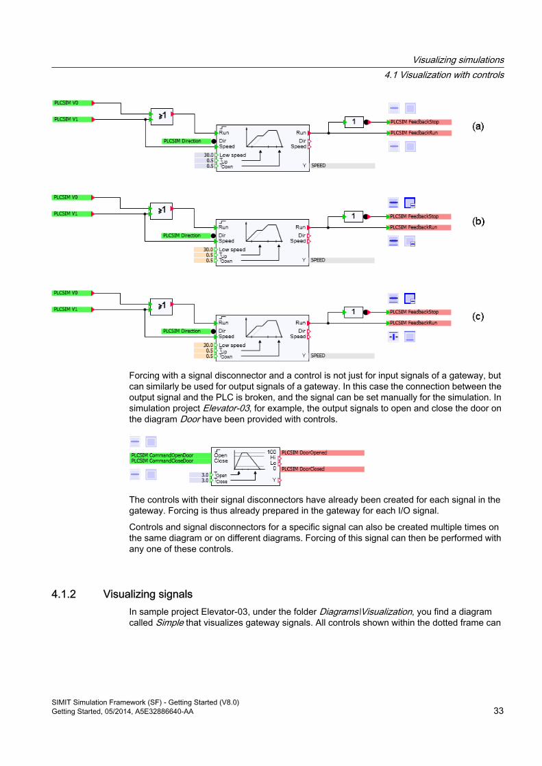
Forcing with a signal disconnector and a control is not just for input signals of a gateway, but can similarly be used for output signals of a gateway. In this case the connection between the output signal and the PLC is broken, and the signal can be set manually for the simulation. In simulation project Elevator-03, for example, the output signals to open and close the door on the diagram Door have been provided with controls.
The controls with their signal disconnectors have already been created for each signal in the gateway. Forcing is thus already prepared in the gateway for each I/O signal.
Controls and signal disconnectors for a specific signal can also be created multiple times on the same diagram or on different diagrams. Forcing of this signal can then be performed with any one of these controls.
4.1.2 Visualizing signalsIn sample project Elevator-03, under the folder Diagrams\Visualization, you find a diagram called Simple that visualizes gateway signals. All controls shown within the dotted frame can
Visualizing simulations4.1 Visualization with controls
SIMIT Simulation Framework (SF) - Getting Started (V8.0)Getting Started, 05/2014, A5E32886640-AA 33
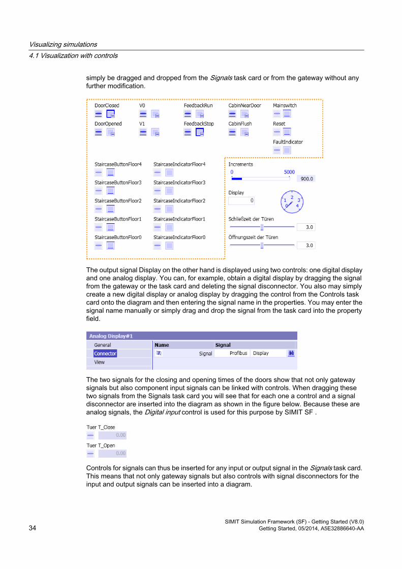
simply be dragged and dropped from the Signals task card or from the gateway without any further modification.
The output signal Display on the other hand is displayed using two controls: one digital display and one analog display. You can, for example, obtain a digital display by dragging the signal from the gateway or the task card and deleting the signal disconnector. You also may simply create a new digital display or analog display by dragging the control from the Controls task card onto the diagram and then entering the signal name in the properties. You may enter the signal name manually or simply drag and drop the signal from the task card into the property field.
The two signals for the closing and opening times of the doors show that not only gateway signals but also component input signals can be linked with controls. When dragging these two signals from the Signals task card you will see that for each one a control and a signal disconnector are inserted into the diagram as shown in the figure below. Because these are analog signals, the Digital input control is used for this purpose by SIMIT SF .
Controls for signals can thus be inserted for any input or output signal in the Signals task card. This means that not only gateway signals but also controls with signal disconnectors for the input and output signals can be inserted into a diagram.
Visualizing simulations4.1 Visualization with controls
SIMIT Simulation Framework (SF) - Getting Started (V8.0)34 Getting Started, 05/2014, A5E32886640-AA
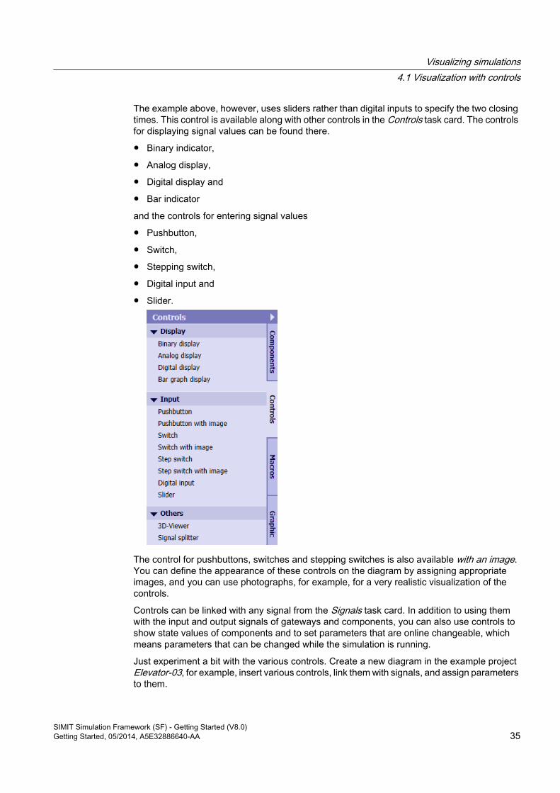
The example above, however, uses sliders rather than digital inputs to specify the two closing times. This control is available along with other controls in the Controls task card. The controls for displaying signal values can be found there.
● Binary indicator,
● Analog display,
● Digital display and
● Bar indicator
and the controls for entering signal values
● Pushbutton,
● Switch,
● Stepping switch,
● Digital input and
● Slider.
The control for pushbuttons, switches and stepping switches is also available with an image. You can define the appearance of these controls on the diagram by assigning appropriate images, and you can use photographs, for example, for a very realistic visualization of the controls.
Controls can be linked with any signal from the Signals task card. In addition to using them with the input and output signals of gateways and components, you can also use controls to show state values of components and to set parameters that are online changeable, which means parameters that can be changed while the simulation is running.
Just experiment a bit with the various controls. Create a new diagram in the example project Elevator-03, for example, insert various controls, link them with signals, and assign parameters to them.
Visualizing simulations4.1 Visualization with controls
SIMIT Simulation Framework (SF) - Getting Started (V8.0)Getting Started, 05/2014, A5E32886640-AA 35
4.2 Visualization with graphics
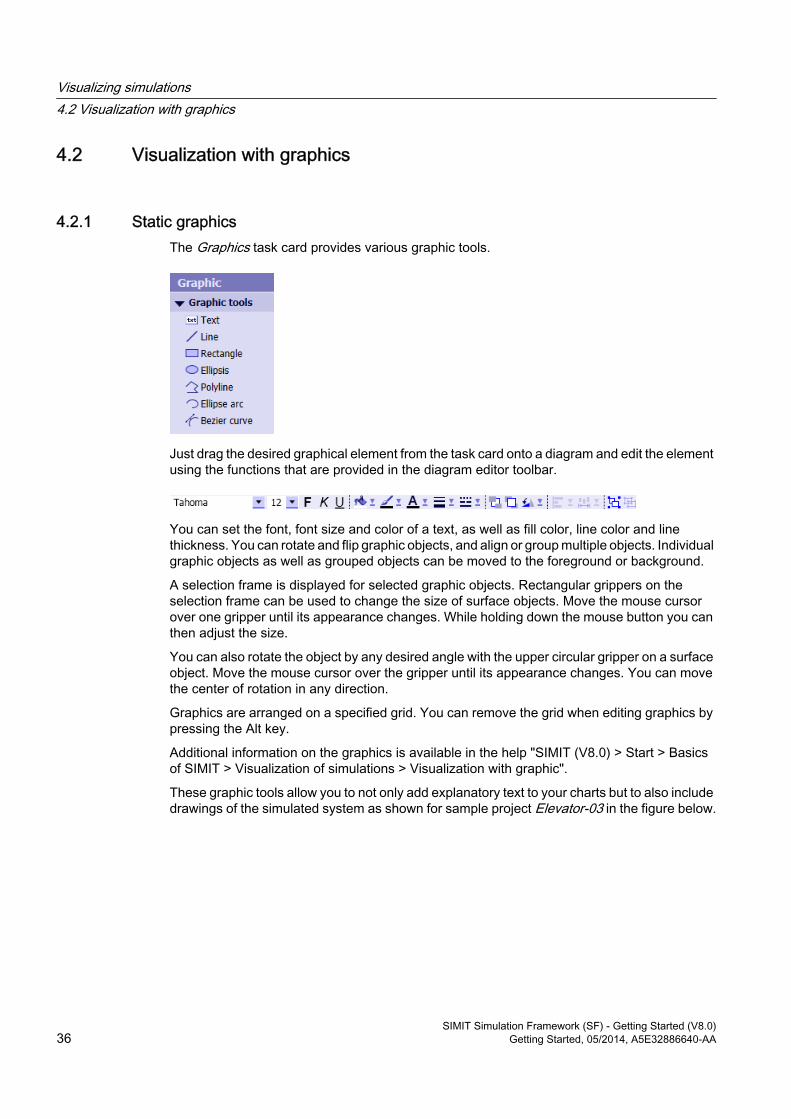
4.2.1 Static graphicsThe Graphics task card provides various graphic tools.
Just drag the desired graphical element from the task card onto a diagram and edit the element using the functions that are provided in the diagram editor toolbar.
You can set the font, font size and color of a text, as well as fill color, line color and line thickness. You can rotate and flip graphic objects, and align or group multiple objects. Individual graphic objects as well as grouped objects can be moved to the foreground or background.
A selection frame is displayed for selected graphic objects. Rectangular grippers on the selection frame can be used to change the size of surface objects. Move the mouse cursor over one gripper until its appearance changes. While holding down the mouse button you can then adjust the size.
You can also rotate the object by any desired angle with the upper circular gripper on a surface object. Move the mouse cursor over the gripper until its appearance changes. You can move the center of rotation in any direction.
Graphics are arranged on a specified grid. You can remove the grid when editing graphics by pressing the Alt key.
Additional information on the graphics is available in the help "SIMIT (V8.0) > Start > Basics of SIMIT > Visualization of simulations > Visualization with graphic".
These graphic tools allow you to not only add explanatory text to your charts but to also include drawings of the simulated system as shown for sample project Elevator-03 in the figure below.
Visualizing simulations4.2 Visualization with graphics
SIMIT Simulation Framework (SF) - Getting Started (V8.0)36 Getting Started, 05/2014, A5E32886640-AA
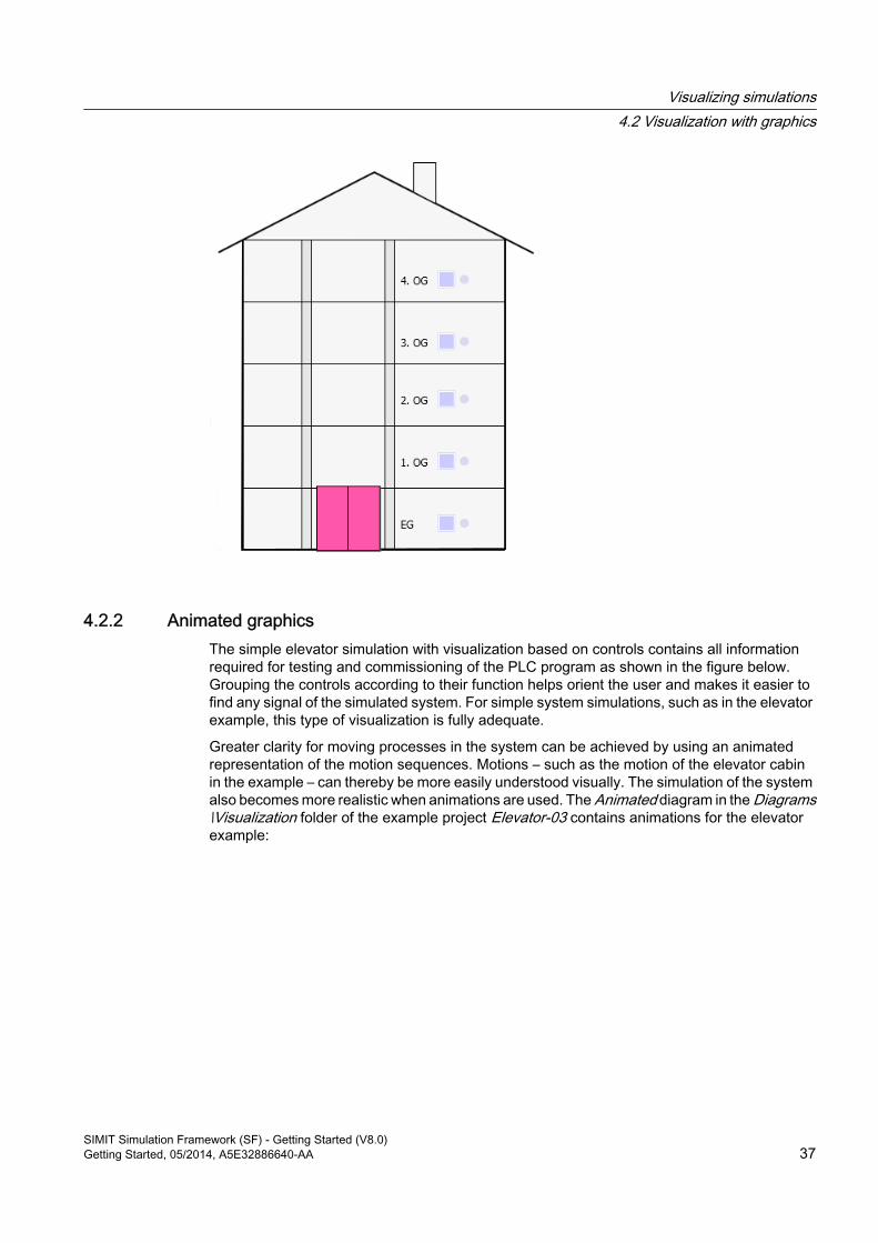
4.2.2 Animated graphicsThe simple elevator simulation with visualization based on controls contains all information required for testing and commissioning of the PLC program as shown in the figure below. Grouping the controls according to their function helps orient the user and makes it easier to find any signal of the simulated system. For simple system simulations, such as in the elevator example, this type of visualization is fully adequate.
Greater clarity for moving processes in the system can be achieved by using an animated representation of the motion sequences. Motions – such as the motion of the elevator cabin in the example – can thereby be more easily understood visually. The simulation of the system also becomes more realistic when animations are used. The Animated diagram in the Diagrams\Visualization folder of the example project Elevator-03 contains animations for the elevator example:
Visualizing simulations4.2 Visualization with graphics
SIMIT Simulation Framework (SF) - Getting Started (V8.0)Getting Started, 05/2014, A5E32886640-AA 37
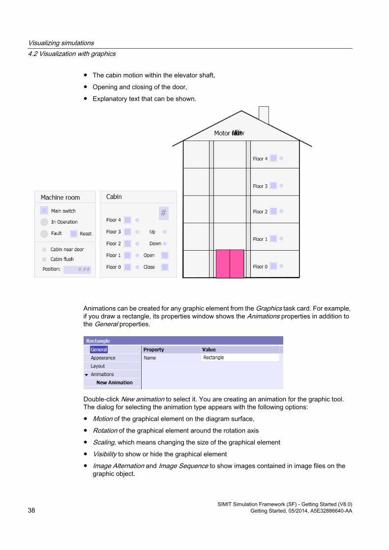
● The cabin motion within the elevator shaft,
● Opening and closing of the door,
● Explanatory text that can be shown.
Animations can be created for any graphic element from the Graphics task card. For example, if you draw a rectangle, its properties window shows the Animations properties in addition to the General properties.
Double-click New animation to select it. You are creating an animation for the graphic tool. The dialog for selecting the animation type appears with the following options:
● Motion of the graphical element on the diagram surface,
● Rotation of the graphical element around the rotation axis
● Scaling, which means changing the size of the graphical element
● Visibility to show or hide the graphical element
● Image Alternation and Image Sequence to show images contained in image files on the graphic object.
Visualizing simulations4.2 Visualization with graphics
SIMIT Simulation Framework (SF) - Getting Started (V8.0)38 Getting Started, 05/2014, A5E32886640-AA
You may define several animations for a single graphical element and can both move and scale an object, for example. Image alternation and image sequence are mutually exclusive, which means you can only create an image alternation or an image sequence.
● Select the motion.A copy of the graphic object appears offset from the original object. A red arrow connects the copy with the original element. This red arrow visualizes the motion of the object. Now use the mouse to move the copy to the required final position.
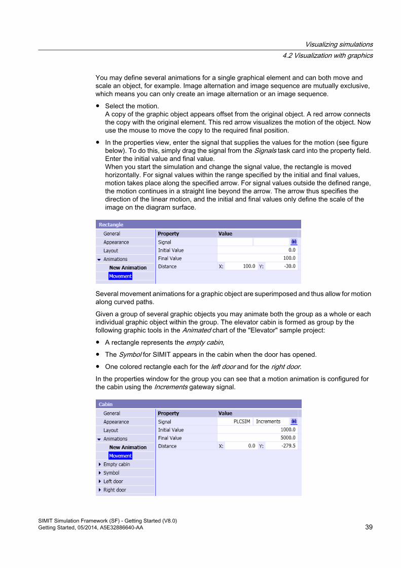
● In the properties view, enter the signal that supplies the values for the motion (see figure below). To do this, simply drag the signal from the Signals task card into the property field. Enter the initial value and final value. When you start the simulation and change the signal value, the rectangle is moved horizontally. For signal values within the range specified by the initial and final values, motion takes place along the specified arrow. For signal values outside the defined range, the motion continues in a straight line beyond the arrow. The arrow thus specifies the direction of the linear motion, and the initial and final values only define the scale of the image on the diagram surface.
Several movement animations for a graphic object are superimposed and thus allow for motion along curved paths.
Given a group of several graphic objects you may animate both the group as a whole or each individual graphic object within the group. The elevator cabin is formed as group by the following graphic tools in the Animated chart of the "Elevator" sample project:
● A rectangle represents the empty cabin,
● The Symbol for SIMIT appears in the cabin when the door has opened.
● One colored rectangle each for the left door and for the right door.In the properties window for the group you can see that a motion animation is configured for the cabin using the Increments gateway signal.
Visualizing simulations4.2 Visualization with graphics
SIMIT Simulation Framework (SF) - Getting Started (V8.0)Getting Started, 05/2014, A5E32886640-AA 39
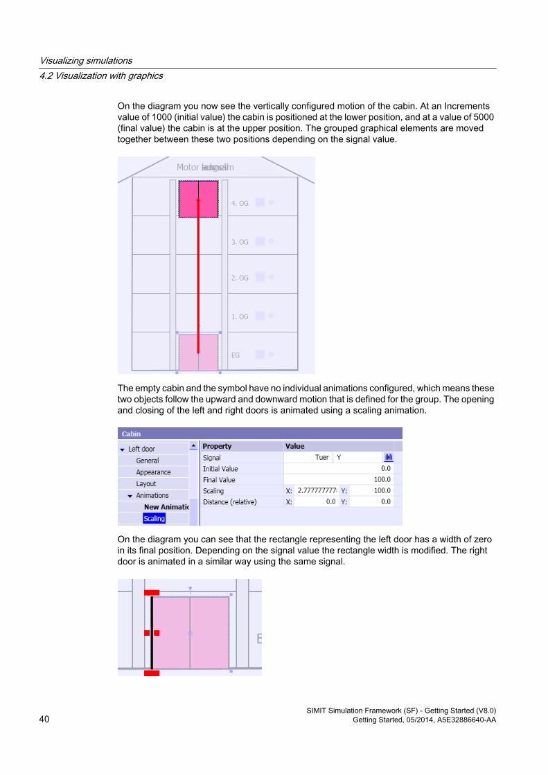
On the diagram you now see the vertically configured motion of the cabin. At an Increments value of 1000 (initial value) the cabin is positioned at the lower position, and at a value of 5000 (final value) the cabin is at the upper position. The grouped graphical elements are moved together between these two positions depending on the signal value.
The empty cabin and the symbol have no individual animations configured, which means these two objects follow the upward and downward motion that is defined for the group. The opening and closing of the left and right doors is animated using a scaling animation.
On the diagram you can see that the rectangle representing the left door has a width of zero in its final position. Depending on the signal value the rectangle width is modified. The right door is animated in a similar way using the same signal.
Visualizing simulations4.2 Visualization with graphics
SIMIT Simulation Framework (SF) - Getting Started (V8.0)40 Getting Started, 05/2014, A5E32886640-AA
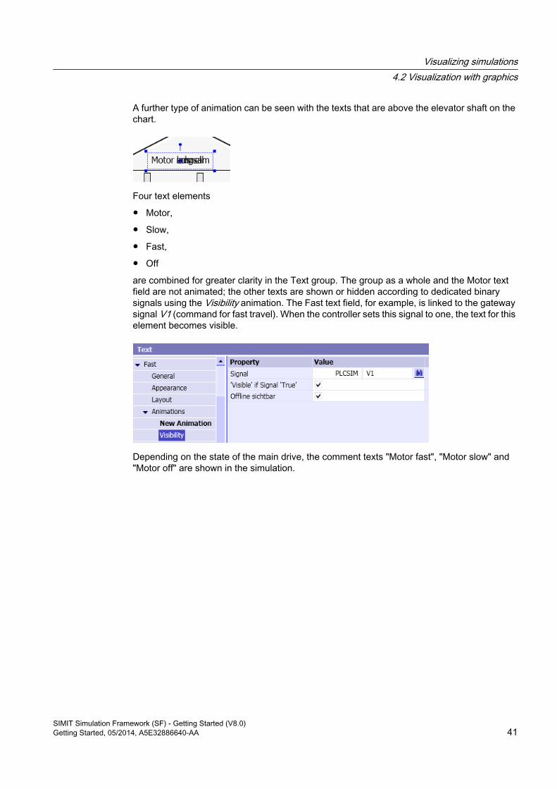
A further type of animation can be seen with the texts that are above the elevator shaft on the chart.
Four text elements
● Motor,
● Slow,
● Fast,
● Off
are combined for greater clarity in the Text group. The group as a whole and the Motor text field are not animated; the other texts are shown or hidden according to dedicated binary signals using the Visibility animation. The Fast text field, for example, is linked to the gateway signal V1 (command for fast travel). When the controller sets this signal to one, the text for this element becomes visible.
Depending on the state of the main drive, the comment texts "Motor fast", "Motor slow" and "Motor off" are shown in the simulation.
Visualizing simulations4.2 Visualization with graphics
SIMIT Simulation Framework (SF) - Getting Started (V8.0)Getting Started, 05/2014, A5E32886640-AA 41

Simulation with Macro Components 55.1 Creating macro components
A macro component allows you to combine frequently recurring functions of a simulation model. You no longer need to copy the function from one chart and paste it to another, rather you can use the macro component similarly to a standard component and drag it from the task card, assign parameters to it and link it to other components or macro components.
Macro components are provided in the Macros task card in the chart editor. You can create your own macro components in either the User Macros or the Project Macros palette. Macro components created in the User Macros palette are stored in the SIMIT SF work area and are therefore available for all projects.
Macro components in the Project macros palette are saved in the project folder. They are only available while this project is open. All macro components stored in Project Macros are archived with the project. Therefore they are available in the project again when you retrieve the project.
Additional information is available in the help "SIMIT (V8.0) > Simulation model > The task cards > Die Task Card "Makros".
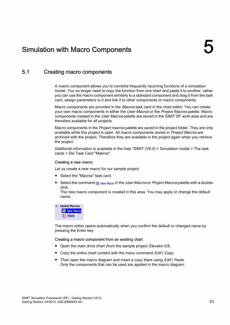
Creating a new macroLet us create a new macro for our sample project.
● Select the "Macros" task card.
● Select the command in the User Macros or Project Macros palette with a double-click. The new macro component is created in this area. You may apply or change the default name.
The macro editor opens automatically when you confirm the default or changed name by pressing the Enter key.
Creating a macro component from an existing chart● Open the main drive chart (from the sample project Elevator-03).
● Copy the entire chart content with the menu command Edit | Copy.
● Then open the macro diagram and insert a copy there using Edit | Paste.Only the components that can be used are applied in the macro diagram.
SIMIT Simulation Framework (SF) - Getting Started (V8.0)Getting Started, 05/2014, A5E32886640-AA 43
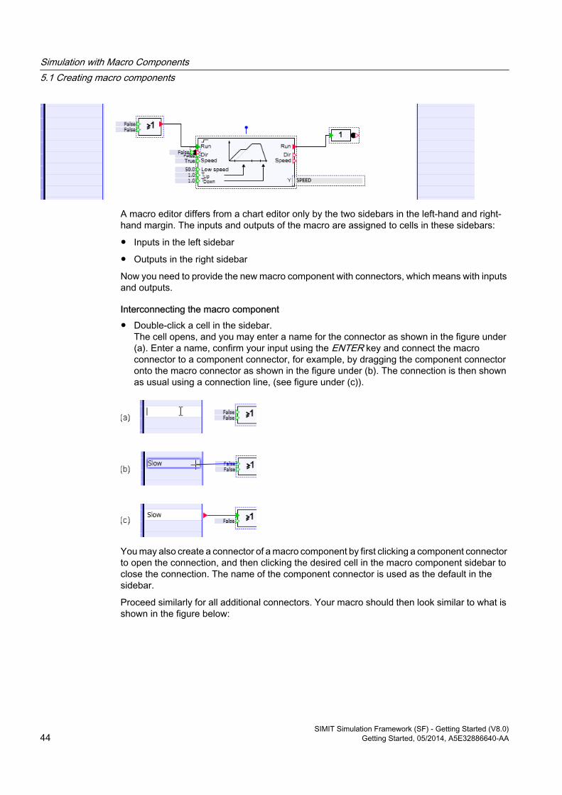
A macro editor differs from a chart editor only by the two sidebars in the left-hand and right-hand margin. The inputs and outputs of the macro are assigned to cells in these sidebars:
● Inputs in the left sidebar
● Outputs in the right sidebar
Now you need to provide the new macro component with connectors, which means with inputs and outputs.
Interconnecting the macro component● Double-click a cell in the sidebar.
The cell opens, and you may enter a name for the connector as shown in the figure under (a). Enter a name, confirm your input using the ENTER key and connect the macro connector to a component connector, for example, by dragging the component connector onto the macro connector as shown in the figure under (b). The connection is then shown as usual using a connection line, (see figure under (c)).
You may also create a connector of a macro component by first clicking a component connector to open the connection, and then clicking the desired cell in the macro component sidebar to close the connection. The name of the component connector is used as the default in the sidebar.
Proceed similarly for all additional connectors. Your macro should then look similar to what is shown in the figure below:
Simulation with Macro Components5.1 Creating macro components
SIMIT Simulation Framework (SF) - Getting Started (V8.0)44 Getting Started, 05/2014, A5E32886640-AA
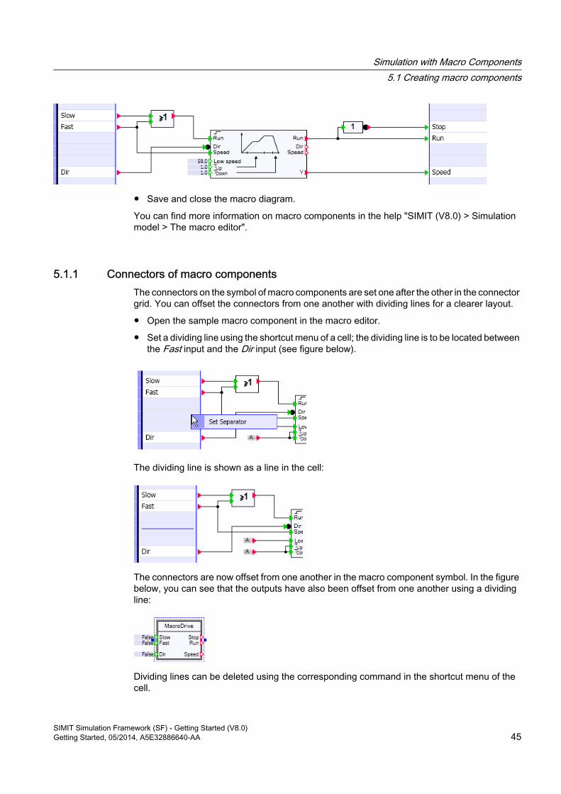
● Save and close the macro diagram.
You can find more information on macro components in the help "SIMIT (V8.0) > Simulation model > The macro editor".
5.1.1 Connectors of macro componentsThe connectors on the symbol of macro components are set one after the other in the connector grid. You can offset the connectors from one another with dividing lines for a clearer layout.
● Open the sample macro component in the macro editor.
● Set a dividing line using the shortcut menu of a cell; the dividing line is to be located between the Fast input and the Dir input (see figure below).
The dividing line is shown as a line in the cell:
The connectors are now offset from one another in the macro component symbol. In the figure below, you can see that the outputs have also been offset from one another using a dividing line:
Dividing lines can be deleted using the corresponding command in the shortcut menu of the cell.
Simulation with Macro Components5.1 Creating macro components
SIMIT Simulation Framework (SF) - Getting Started (V8.0)Getting Started, 05/2014, A5E32886640-AA 45
You can also use components from the FLOWNET and CONTEC extension libraries in macro components. Open topological connectors of a model created from FLOWNET or CONTEC components are simply mapped to topological connectors in the sidebars of the macro component.
You can find more information on this topic in the help "SIMIT (V8.0) > Simulation model > The macro editor (MCE) > Create macro components".
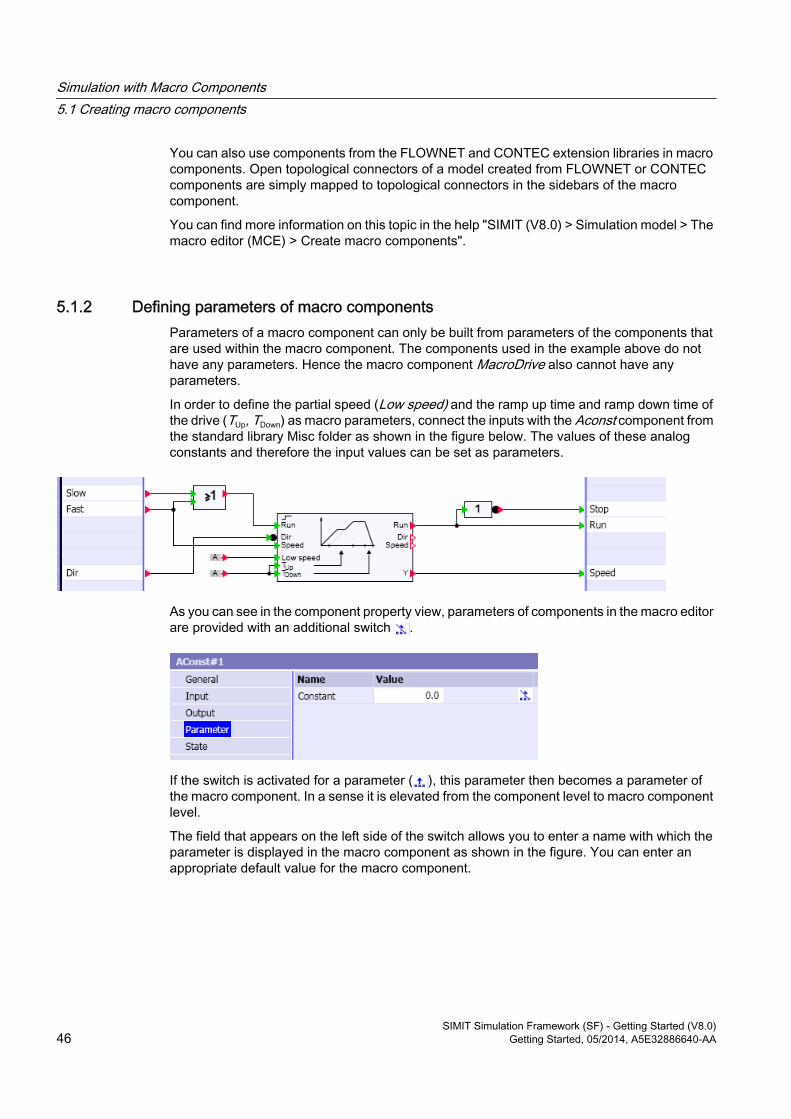
5.1.2 Defining parameters of macro componentsParameters of a macro component can only be built from parameters of the components that are used within the macro component. The components used in the example above do not have any parameters. Hence the macro component MacroDrive also cannot have any parameters.
In order to define the partial speed (Low speed) and the ramp up time and ramp down time of the drive (TUp, TDown) as macro parameters, connect the inputs with the Aconst component from the standard library Misc folder as shown in the figure below. The values of these analog constants and therefore the input values can be set as parameters.
As you can see in the component property view, parameters of components in the macro editor are provided with an additional switch .
If the switch is activated for a parameter ( ), this parameter then becomes a parameter of the macro component. In a sense it is elevated from the component level to macro component level.
The field that appears on the left side of the switch allows you to enter a name with which the parameter is displayed in the macro component as shown in the figure. You can enter an appropriate default value for the macro component.
Simulation with Macro Components5.1 Creating macro components
SIMIT Simulation Framework (SF) - Getting Started (V8.0)46 Getting Started, 05/2014, A5E32886640-AA
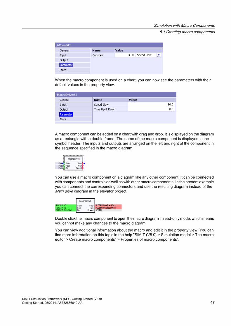
When the macro component is used on a chart, you can now see the parameters with their default values in the property view.
A macro component can be added on a chart with drag and drop. It is displayed on the diagram as a rectangle with a double frame. The name of the macro component is displayed in the symbol header. The inputs and outputs are arranged on the left and right of the component in the sequence specified in the macro diagram.
You can use a macro component on a diagram like any other component. It can be connected with components and controls as well as with other macro components. In the present example you can connect the corresponding connectors and use the resulting diagram instead of the Main drive diagram in the elevator project.
Double click the macro component to open the macro diagram in read-only mode, which means you cannot make any changes to the macro diagram.
You can view additional information about the macro and edit it in the property view. You can find more information on this topic in the help "SIMIT (V8.0) > Simulation model > The macro editor > Create macro components" > Properties of macro components".
Simulation with Macro Components5.1 Creating macro components
SIMIT Simulation Framework (SF) - Getting Started (V8.0)Getting Started, 05/2014, A5E32886640-AA 47


Functions in the Project Manager 66.1 The Project Manager and the "Projects" task card
The Project ManagerYou open the Project Manager with a double-click on the menu item Project Manager in the project navigation. The Project Manager shows an alternative view of the project compared to the project navigation.
Just like the project navigation the Project Manager allows you to move charts and other project elements as well as entire folders via drag and drop or to use commands in the shortcut menu to copy, paste, delete, or rename them. In the Project Manager, you can also double-click project elements such as charts to open them for editing.
The "Projects" task cardThe Project Manager provides the Projects task card. This task card allows you to open projects other than the one you are currently editing to copy elements from these projects into your project. For example, retrieve the projects Elevator-01 and Elevator-03 into two different project folders and then open the Elevator-01 project in SIMIT SF. Now open the Project Manager. Click (Open Project) in the Projects task card. In the file selection dialog that appears, navigate to the project folder for Elevator-03 and select the Elevator-03.simit project file. The project is then opened in read-only mode in the Projects task card.
SIMIT Simulation Framework (SF) - Getting Started (V8.0)Getting Started, 05/2014, A5E32886640-AA 49
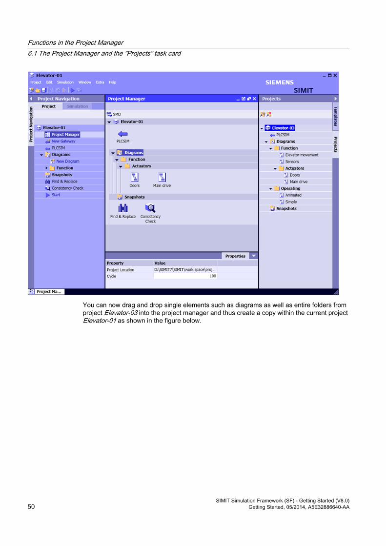
You can now drag and drop single elements such as diagrams as well as entire folders from project Elevator-03 into the project manager and thus create a copy within the current project Elevator-01 as shown in the figure below.
Functions in the Project Manager6.1 The Project Manager and the "Projects" task card
SIMIT Simulation Framework (SF) - Getting Started (V8.0)50 Getting Started, 05/2014, A5E32886640-AA
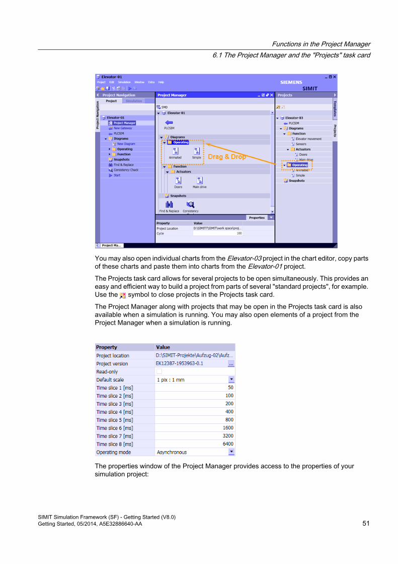
You may also open individual charts from the Elevator-03 project in the chart editor, copy parts of these charts and paste them into charts from the Elevator-01 project.
The Projects task card allows for several projects to be open simultaneously. This provides an easy and efficient way to build a project from parts of several "standard projects", for example. Use the symbol to close projects in the Projects task card.
The Project Manager along with projects that may be open in the Projects task card is also available when a simulation is running. You may also open elements of a project from the Project Manager when a simulation is running.
The properties window of the Project Manager provides access to the properties of your simulation project:
Functions in the Project Manager6.1 The Project Manager and the "Projects" task card
SIMIT Simulation Framework (SF) - Getting Started (V8.0)Getting Started, 05/2014, A5E32886640-AA 51

● The Project location indicates which folder your project is located in.
● The Project version shows the current project version.
● The property Read-only shows if the project is read-only.
● The Default scale if you use the CONTEC library.
● The eight different time slices (time slice 1 to time slice 8) for the eight time slices which you can assign to components, controls and couplings in your project, can be assigned any value in milliseconds, provided it is at least 10 ms.
● The Operating mode shows if synchronous or asynchronous operating mode is set.
You can find more information in the help "SIMIT (V8.0) > Simulation model > The Project Manager".
Information on the operating mode is available in the help "SIMIT (V8.0) > Start > Basics of SIMIT > Virtual Time Management > Synchronous and asynchronous operating mode".
Functions in the Project Manager6.1 The Project Manager and the "Projects" task card
SIMIT Simulation Framework (SF) - Getting Started (V8.0)52 Getting Started, 05/2014, A5E32886640-AA
Automatic mechanisms 7
SIMIT provides several automatic mechanisms to create and edit diagrams. All these automatic mechanisms are based on files that contain information to create or modify diagrams. This information is automatically converted into diagrams once the corresponding files are imported into SIMIT. The following automatic mechanisms are available:
● TemplatesTemplates are patterns for diagrams in which placeholders are defined for parameters, defaults, etc. When a table is imported in which values are set for the placeholders, the diagrams are automatically generated from the templates.
● Parameter importParameters and input default values can be defined in a table and can be imported into the simulation project by importing the table.
● XML interfaceDiagrams cannot only be created using the graphical user interface but also based on a description that is written in XML syntax. This description is stored in a file. By importing this file you automatically create the defined charts.Additional information on the XML interface is available in the help "SIMIT (V8.0) > Automatic model creation > Generic import".
7.1 Templates
7.1.1 Creating and editing templatesTemplates are used to prepare recurring functions of a simulation model so that you can use the templates for charts when creating projects. You may use all of the same elements in templates that you use in charts: components, macro components, controls and graphics. In templates, unlike in charts, only placeholders are used for various elements of the components, controls, etc. that are contained in charts. When instantiating a template, a chart is generated in which the placeholders are substituted by values, signal names, etc. SIMIT SF offers you two options for instantiating templates: "Drag-and-Drop" the template to the project and import a table containing the values for the placeholders which can then be used to create charts automatically.
Creating templatesTo create a template open the Templates task card in the Project Manager. Use
to open the templates editor and create a new template. To open a template for editing just double-click the template in the Templates task card. The template editor provides the task cards Components, Controls, Macros and Graphics as resources, which means the same elements are available to you as for editing a chart.
SIMIT Simulation Framework (SF) - Getting Started (V8.0)Getting Started, 05/2014, A5E32886640-AA 53
Templates in the Basic palette can only be opened for viewing in the templates editor, which means you cannot edit these templates. To indicate this the template is opened in the editor with a white title bar. If you wish to edit a basic template, first copy it to the User templates palette.
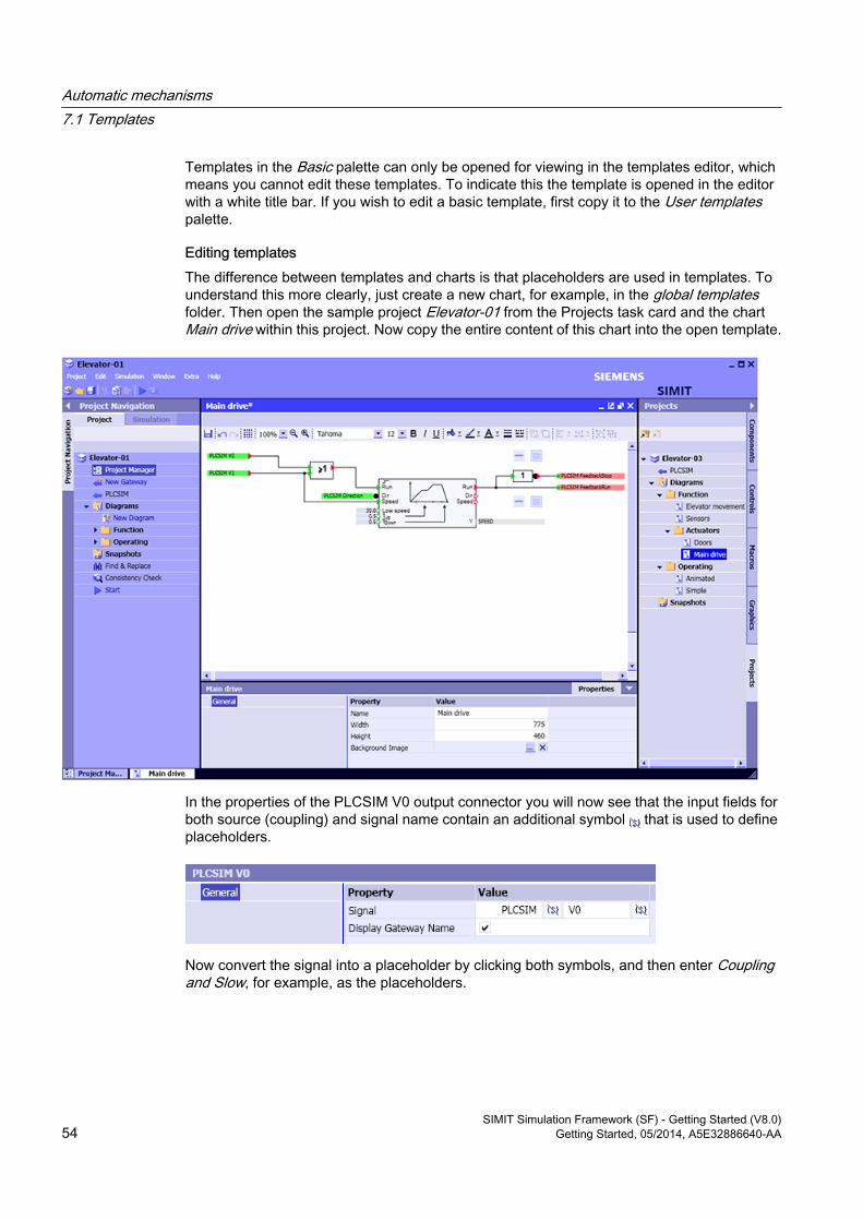
Editing templatesThe difference between templates and charts is that placeholders are used in templates. To understand this more clearly, just create a new chart, for example, in the global templates folder. Then open the sample project Elevator-01 from the Projects task card and the chart Main drive within this project. Now copy the entire content of this chart into the open template.
In the properties of the PLCSIM V0 output connector you will now see that the input fields for both source (coupling) and signal name contain an additional symbol that is used to define placeholders.
Now convert the signal into a placeholder by clicking both symbols, and then enter Coupling and Slow, for example, as the placeholders.
Automatic mechanisms 7.1 Templates
SIMIT Simulation Framework (SF) - Getting Started (V8.0)54 Getting Started, 05/2014, A5E32886640-AA
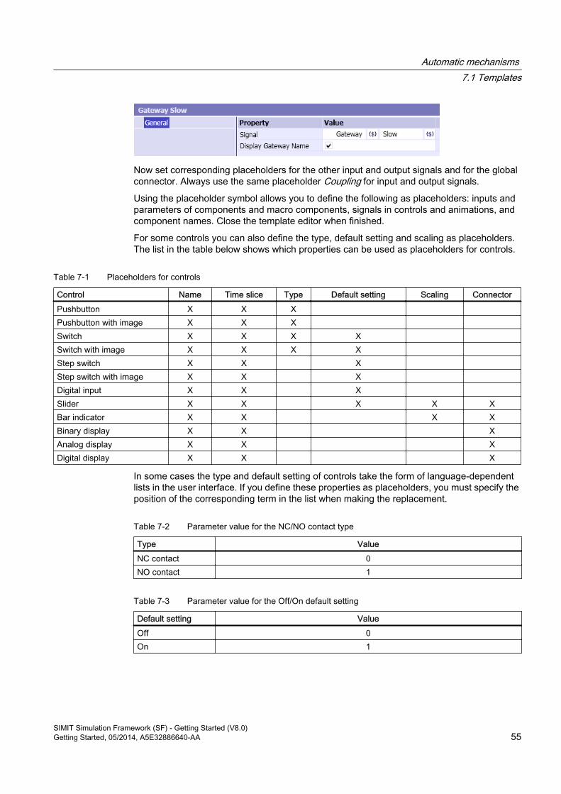
Now set corresponding placeholders for the other input and output signals and for the global connector. Always use the same placeholder Coupling for input and output signals.
Using the placeholder symbol allows you to define the following as placeholders: inputs and parameters of components and macro components, signals in controls and animations, and component names. Close the template editor when finished.
For some controls you can also define the type, default setting and scaling as placeholders. The list in the table below shows which properties can be used as placeholders for controls.
Table 7-1 Placeholders for controls
Control Name Time slice Type Default setting Scaling ConnectorPushbutton X X X Pushbutton with image X X X Switch X X X X Switch with image X X X X Step switch X X X Step switch with image X X X Digital input X X X Slider X X X X XBar indicator X X X XBinary display X X XAnalog display X X XDigital display X X X
In some cases the type and default setting of controls take the form of language-dependent lists in the user interface. If you define these properties as placeholders, you must specify the position of the corresponding term in the list when making the replacement.
Table 7-2 Parameter value for the NC/NO contact type
Type ValueNC contact 0NO contact 1
Table 7-3 Parameter value for the Off/On default setting
Default setting ValueOff 0On 1
Automatic mechanisms 7.1 Templates
SIMIT Simulation Framework (SF) - Getting Started (V8.0)Getting Started, 05/2014, A5E32886640-AA 55
7.1.2 Instantiating templates
You may use tables as an alternative means of instantiating templates. These tables mainly contain substitutions for the placeholders. Depending on the profile the table contains additional information about which templates to use and which instances to create. In addition to the profile for IEA files from PCS 7, three profiles are provided for tables based on CSV files:
● Profile 1 using predefined placeholders "V1", "V2", etc.
● Profile 2 with placeholders in the first row
● Profile 3 with individually listed placeholders
In all tables, each row defines the instantiation of one template.
The following table formats are supported:
● *.ieaThe table format used by the Import/Export wizards in PCS 7.
● *.xls The Microsoft Excel format for Office 97 – 2003. Only the first sheet of the workbook is taken into account. This file format is only available if Microsoft Excel is installed on your computer.
● *.xlsxThe current Microsoft Excel format. Only the first sheet of the workbook is taken into account. This file format is available even if Microsoft Excel is not installed on your computer.
● *.txtTab-separated list in text format.
You can find more information in the help "SIMIT (V8.0) > Automatic model creation > Templates".
7.1.2.1 Instantiating templates by entering substitutionsTemplates are instantiated by replacing placeholders with appropriate values. Components whose names are not defined as placeholders are instantiated as if they had been dragged and dropped from the library, which means they are assigned the name of their component type along with a consecutive number as a name.
In the Project Manager, you may instantiate a template simply by dragging and dropping it from the task card into a project folder. Open the project manager and select the Templates task card. If you now drag the template that was created above, a dialog appears as shown in the figure below. A two-column list is displayed, which shows all of the placeholders that are contained in this template. Please enter the substitution for each placeholder in the right-hand column.
Automatic mechanisms 7.1 Templates
SIMIT Simulation Framework (SF) - Getting Started (V8.0)56 Getting Started, 05/2014, A5E32886640-AA
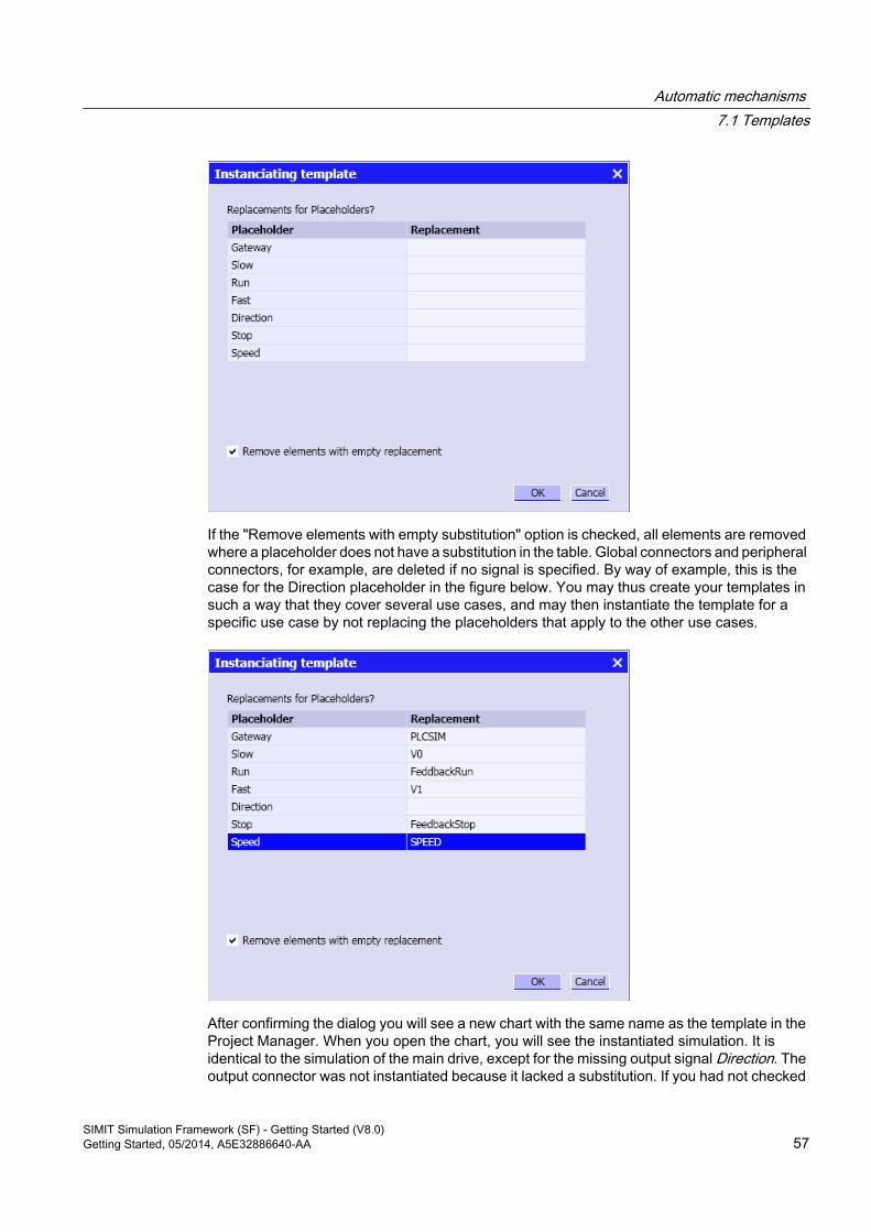
If the "Remove elements with empty substitution" option is checked, all elements are removed where a placeholder does not have a substitution in the table. Global connectors and peripheral connectors, for example, are deleted if no signal is specified. By way of example, this is the case for the Direction placeholder in the figure below. You may thus create your templates in such a way that they cover several use cases, and may then instantiate the template for a specific use case by not replacing the placeholders that apply to the other use cases.
After confirming the dialog you will see a new chart with the same name as the template in the Project Manager. When you open the chart, you will see the instantiated simulation. It is identical to the simulation of the main drive, except for the missing output signal Direction. The output connector was not instantiated because it lacked a substitution. If you had not checked
Automatic mechanisms 7.1 Templates
SIMIT Simulation Framework (SF) - Getting Started (V8.0)Getting Started, 05/2014, A5E32886640-AA 57
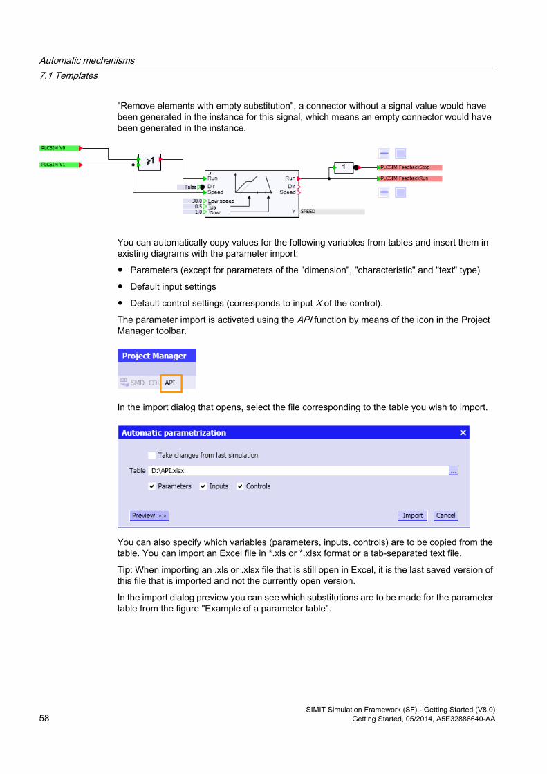
"Remove elements with empty substitution", a connector without a signal value would have been generated in the instance for this signal, which means an empty connector would have been generated in the instance.
You can automatically copy values for the following variables from tables and insert them in existing diagrams with the parameter import:
● Parameters (except for parameters of the "dimension", "characteristic" and "text" type)
● Default input settings
● Default control settings (corresponds to input X of the control).
The parameter import is activated using the API function by means of the icon in the Project Manager toolbar.
In the import dialog that opens, select the file corresponding to the table you wish to import.
You can also specify which variables (parameters, inputs, controls) are to be copied from the table. You can import an Excel file in *.xls or *.xlsx format or a tab-separated text file.
Tip: When importing an .xls or .xlsx file that is still open in Excel, it is the last saved version of this file that is imported and not the currently open version.
In the import dialog preview you can see which substitutions are to be made for the parameter table from the figure "Example of a parameter table".
Automatic mechanisms 7.1 Templates
SIMIT Simulation Framework (SF) - Getting Started (V8.0)58 Getting Started, 05/2014, A5E32886640-AA
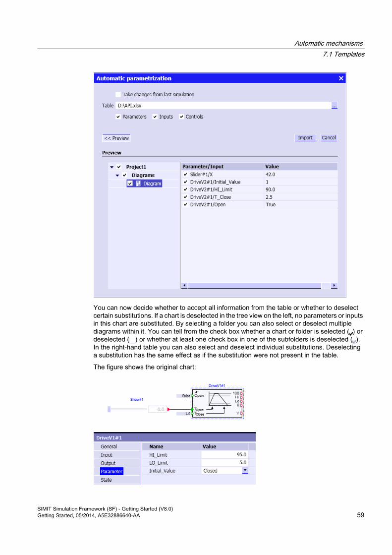
You can now decide whether to accept all information from the table or whether to deselect certain substitutions. If a chart is deselected in the tree view on the left, no parameters or inputs in this chart are substituted. By selecting a folder you can also select or deselect multiple diagrams within it. You can tell from the check box whether a chart or folder is selected ( ) or deselected ( ) or whether at least one check box in one of the subfolders is deselected ( ). In the right-hand table you can also select and deselect individual substitutions. Deselecting a substitution has the same effect as if the substitution were not present in the table.
The figure shows the original chart:
Automatic mechanisms 7.1 Templates
SIMIT Simulation Framework (SF) - Getting Started (V8.0)Getting Started, 05/2014, A5E32886640-AA 59
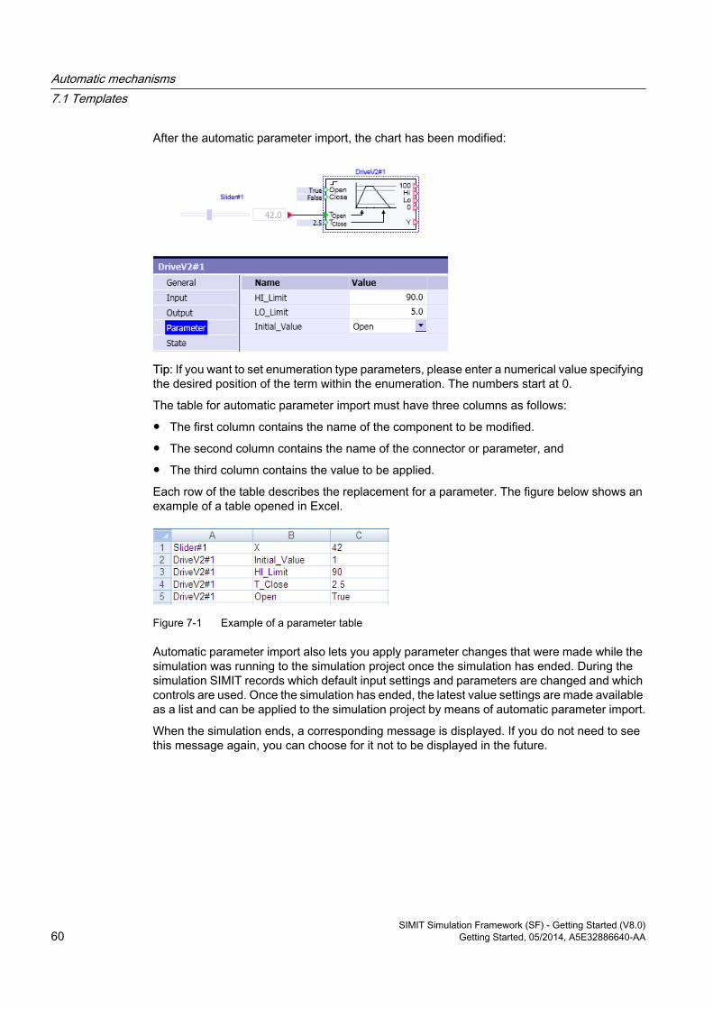
After the automatic parameter import, the chart has been modified:
Tip: If you want to set enumeration type parameters, please enter a numerical value specifying the desired position of the term within the enumeration. The numbers start at 0.
The table for automatic parameter import must have three columns as follows:
● The first column contains the name of the component to be modified.
● The second column contains the name of the connector or parameter, and
● The third column contains the value to be applied.
Each row of the table describes the replacement for a parameter. The figure below shows an example of a table opened in Excel.
Figure 7-1 Example of a parameter table
Automatic parameter import also lets you apply parameter changes that were made while the simulation was running to the simulation project once the simulation has ended. During the simulation SIMIT records which default input settings and parameters are changed and which controls are used. Once the simulation has ended, the latest value settings are made available as a list and can be applied to the simulation project by means of automatic parameter import.
When the simulation ends, a corresponding message is displayed. If you do not need to see this message again, you can choose for it not to be displayed in the future.
Automatic mechanisms 7.1 Templates
SIMIT Simulation Framework (SF) - Getting Started (V8.0)60 Getting Started, 05/2014, A5E32886640-AA
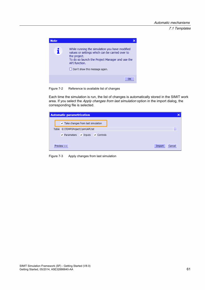
Figure 7-2 Reference to available list of changes
Each time the simulation is run, the list of changes is automatically stored in the SIMIT work area. If you select the Apply changes from last simulation option in the import dialog, the corresponding file is selected.
Figure 7-3 Apply changes from last simulation
Automatic mechanisms 7.1 Templates
SIMIT Simulation Framework (SF) - Getting Started (V8.0)Getting Started, 05/2014, A5E32886640-AA 61

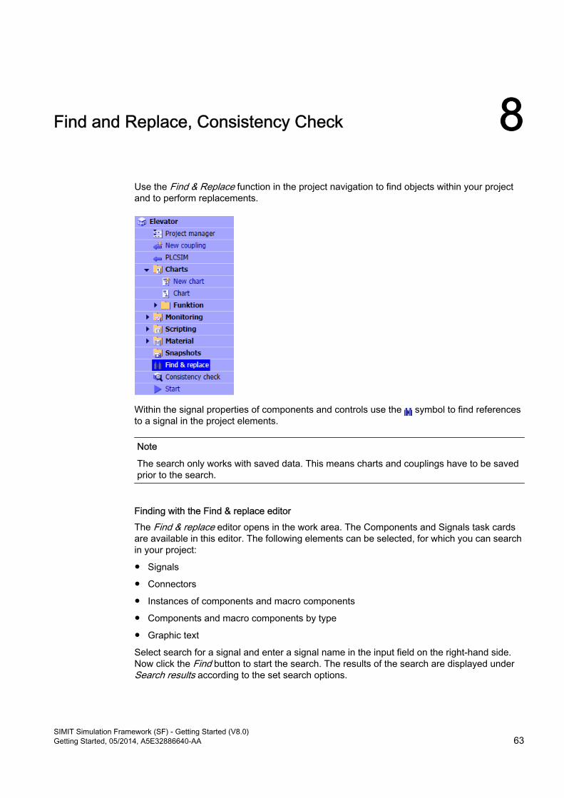
Find and Replace, Consistency Check 8
Use the Find & Replace function in the project navigation to find objects within your project and to perform replacements.
Within the signal properties of components and controls use the symbol to find references to a signal in the project elements.
Note
The search only works with saved data. This means charts and couplings have to be saved prior to the search.
Finding with the Find & replace editorThe Find & replace editor opens in the work area. The Components and Signals task cards are available in this editor. The following elements can be selected, for which you can search in your project:
● Signals
● Connectors
● Instances of components and macro components
● Components and macro components by type
● Graphic text
Select search for a signal and enter a signal name in the input field on the right-hand side. Now click the Find button to start the search. The results of the search are displayed under Search results according to the set search options.
SIMIT Simulation Framework (SF) - Getting Started (V8.0)Getting Started, 05/2014, A5E32886640-AA 63
To search for a specific signal just drag and drop it from the Signals task card into either of the two input fields of the search criteria.
When searching for a component type, enter its name and/or ID. When searching for a specific component type in your project, you may similarly drag and drop a component type from the Components task card into the input field.
To search for components and connectors the name must be specified.
Search using signal propertiesAnother option for finding signals and connectors in a chart is to use their property view. Click
to start the search.
The Find & replace editor will then appear with the search results.
Searching for fixed signalsYou can search specifically for fixed signals in the simulation project. To do this, in the search for signals activate the search option Fixed signals only (see figure "Searching for fixed signals"). In this way you can get an overview at any time of which signals are currently fixed.
Because signals can only be fixed when the simulation is running, this search option is only available when the simulation is running.
ReplaceTo replace search results switch the editor into replace mode using the navigation tab. You can replace
● Signals
● Connectors
● Instances of components and macro components
● Components and macro components by type
● Graphic text
Note
The Replace function only works with saved data. This means charts and couplings have to be saved prior to the replacement.
Now you once again enter a signal name in the search for signals and the name to be replaced in the replacement field. The results are displayed as with the search mode.
In the Search results section you can now select which results you want to replace. Depending on the patterns that were set for the find and replace, you see the results of the replacement that are performed for each search result. As with the search mode, the Project elements section shows all charts in which the signals for which you searched were found.
You can find more information on Find & Replace in the help "SIMIT (V8.0) > Diagnostics & Visualization > Find & replace".
Find and Replace, Consistency Check
SIMIT Simulation Framework (SF) - Getting Started (V8.0)64 Getting Started, 05/2014, A5E32886640-AA
8.1 Consistency checkUse the consistency check to check whether your project is consistent. Inconsistent projects cannot be started. You open the consistency check with a double-click on the menu item Consistency check in the project navigation.
If you rename the SPEED connector as Increments in the Elevator-03 project on the Main drive chart, for example, two output connectors with the same name exist in the project. The project is no longer consistent, and when the project is started the consistency check opens in the work area showing the inconsistencies that were found. Because a consistency check is always performed automatically when the simulation is started, the consistency check editor also shows when you try to start this inconsistent project.
Inconsistencies are indicated by being preceded with the red symbol . Warnings are indicated with the blue symbol . Using a command, you may switch the display on or off for warnings. In the above example there are two results:
1. There is no output connector that matches the input connector SPEED.
2. The output connector Increment exists in several instances.
The first message is only a warning and indicates that the simulation model may not yet be finished. A warning will not keep you from launching the simulation. The second result indicates an error that needs to be fixed before the simulation can be launched.
To fix an error or a warning select its entry in the list of results. The Project elements section shows the diagrams in which the error or warning must be resolved. From this view you may then open the diagrams to fix the problem. After resolving the problem, you may recheck the project using the Recheck button.
You can find more information on this topic in the help "SIMIT (V8.0) > Diagnostics & Visualization > Consistency check".
Find and Replace, Consistency Check8.1 Consistency check
SIMIT Simulation Framework (SF) - Getting Started (V8.0)Getting Started, 05/2014, A5E32886640-AA 65


![Submodulo12[1].2 v8.0](https://img.pdfslide.us/doc/110x75/58ecd3391a28abd7098b46bd/submodulo1212-v80.jpg)