Embed Size (px)
Citation preview
Preface, Contents
Product Overview1
Installing a CPU 41x-2 PCI andPS Extension Board
2
Installing WinAC Slot 41x3
Commissioning4
CPU 412-2 PCI andCPU 416-2 PCI Control Panel
5CPU 41x-2 PCI as DP Master/DPSlave and Direct Data Exchange
6Time Synchronization (WinACTimeSync)
7CPU 412-2 PCI/CPU 416-2 PCI –Tech. Specifications, Compatibility
8
PS Extension Board9
Memory Cards10
Appendix
General Technical Specifications A
Networking BFAQs: Frequently AskedQuestions about WinAC Slot 41x C
Panel Control DSpare Parts and Accessories – Order Numbers EGuidelines for Handling Electro-static Sensitive Devices (ESD) F
List of Abbreviations G
Glossary, Index
WinAC Controlling withCPU 412-2 PCI/CPU 416-2 PCISetting Up, CPU Data Version 3.3
Manual
SIMATIC
This manual is part of the product packages with the order number:6ES7 673-6CC21-0YA06ES7 673-6CC01-0YA0
Edition 01/2003A5E00065507-05
Index-2WinAC Controlling with CPU 412-2 PCI/CPU 416-2 PCI Setting Up, CPU Data Version 3.3
A5E00065507-05
!Danger
indicates that death, severe personal injury or substantial property damage will result if proper precautionsare not taken.
!Warning
indicates that death, severe personal injury or substantial property damage can result if properprecautions are not taken.
!Caution
indicates that minor personal injury can result if proper precautions are not taken.
Caution
indicates that property damage can result if proper precautions are not taken.
Notice
draws your attention to particularly important information on the product, handling the product, or to aparticular part of the documentation.
Qualified PersonnelOnly qualified personnel should be allowed to install and work on this equipment. Qualified persons aredefined as persons who are authorized to commission, to ground and to tag circuits, equipment, andsystems in accordance with established safety practices and standards.
Correct UsageNote the following:
!Warning
This device and its components may only be used for the applications described in the catalog or thetechnical description, and only in connection with devices or components from other manufacturers whichhave been approved or recommended by Siemens.
This product can only function correctly and safely if it is transported, stored, set up, and installedcorrectly, and operated and maintained as recommended.
TrademarksSIMATIC, SIMATIC HMI and SIMATIC NET are registered trademarks of SIEMENS AG.
Third parties using for their own purposes any other names in this document which refer to trademarksmight infringe upon the rights of the trademark owners.
Safety GuidelinesThis manual contains notices intended to ensure personal safety, as well as to protect the products andconnected equipment against damage. These notices are highlighted by the symbols shown below andgraded according to severity by the following texts:
We have checked the contents of this manual for agreementwith the hardware and software described. Since deviationscannot be precluded entirely, we cannot guarantee fullagreement. However, the data in this manual are reviewedregularly and any necessary corrections included insubsequent editions. Suggestions for improvement arewelcomed.
Disclaim of LiabilityCopyright Siemens AG 2001-2002 All rights reserved
The reproduction, transmission or use of this document or itscontents is not permitted without express written authority.Offenders will be liable for damages. All rights, including rightscreated by patent grant or registration of a utility model ordesign, are reserved.
Siemens AGBereich Automation and DrivesGeschaeftsgebiet Industrial Automation SystemsPostfach 4848, D- 90327 Nuernberg
Siemens AG 2001-2002Technical data subject to change.
Siemens Aktiengesellschaft A5E00065507
iiiWinAC Controlling with CPU 412-2 PCI/CPU 416-2 PCI Setting Up, CPU Data Version 3.3A5E00065507-05
Preface
Purpose of the manual
The information contained in this manual will help you to:
configure a programmable logic controller with a CPU 412-2 PCI/416-2 PCI ona PC
look up operator entries, descriptions of functions and technical specifications.
Essential basic skills
To understand the manual, general knowledge of automation engineering isrequired.
In addition, knowledge of the following is required:
Extensive knowledge of the S7-400
Extensive knowledge of STEP 7
Applicability of the manual
The present manual applies to the following modules:
CPU Order No. As of Version
Firmware Hardware
CPU 412-2 PCI 6ES7 612-2QH00-0AB4* 3.1 1
CPU 416-2 PCI 6ES7 616-2QL00-0AB4* 3.1 1
PS extension board 6ES7 678-1RA00-0XB0 - 1
* As spare part
This manual describes all modules that are valid as of the time the manual wasreleased. For new modules or newer versions of modules, we reserve the right toenclose a product information leaflet containing the current information on themodule(s) concerned.
This manual describes the differences of the CPU 412-2 PCI and CPU 416-2 PCIfrom the CPUs in the S7-400 series. You will find additional information in theS7-400 manuals.
Preface
ivWinAC Controlling with CPU 412-2 PCI/CPU 416-2 PCI Setting Up, CPU Data Version 3.3
A5E00065507-05
Changes from the previous version
Compared to the previous version, WinAC Slot 41x, version 3.2, the followingchanges have been implemented (refer also to section 8.4):
WinAC Slot can also be operated under Windows XP Professional
Windows NT 4.0 is no longer supported.
Using SFC 126 “SYNC_PI“ and SFC 127 “SYNC_PO“ you can update processimage partitions synchronous to the DP clock.
Using SFC 103 ”DP_TOPOL” you can determine the bus topology of a DPmaster system by triggering the diagnostics repeater.
Certification
The CPUs 41x-2 PCI and the PS extension board have the following certification:
Underwriters Laboratories, Inc.: UL 508 registered (Industrial Control Equipment)
Canadian Standards Association: CSA C22.2 number 142, (Process Control Equipment)
Factory Mutual Research: Approval Standard Class Number 3611.
CE Labeling
The CPUs 41x-2 PCI and the PS extension board fulfil the requirements andprotection guidelines of the following EU directives:
EC Directive 73/23/EEC “Low–voltage directive”
EC Directive 89/336/EWG “EMC directive”
CTick Mark
The CPUs 41x-2 PCI and the PS extension board are compliant with requirementsof the AS/NZS 2064 (Australian) standard.
Standards
The CPUs 41x-2 PCI and the PS extension board fulfil the requirements andcriteria of IEC 61131-2.
Refer to appendix xx to find out the norms the CPUs are compliant with.
Operation list
The operation list contains a concise summary of all important information relatingto the operation set of all S7-400 CPUs. The data of the CPU 412-2 PCI areidentical to those of CPU 412-2 DP, while the data of the CPU 416-2 PCI are thesame as those for CPU 416-2 DP.
Preface
vWinAC Controlling with CPU 412-2 PCI/CPU 416-2 PCI Setting Up, CPU Data Version 3.3A5E00065507-05
How the manual fits in
This manual describes the differences of the CPU 412-2 PCI and CPU 416-2 PCIfrom the CPUs in the S7-400 series. In addition, you will require the followingdocumentation:
Table 1-1 How the Manual Fits In
Manual/Manual Package Contents
Basic Grounding in STEP7
Getting Started and Exerciseswith STEP 7
Programming with STEP 7
Configuring Hardware andConnections with STEP 7
From S5 To S7, ConversionGuide
The basic grounding for technical staff describing the procedures forimplementing control tasks with STEP 7.
STEP7 reference
LAD/FBD/STL Manual forS7-300/400
Standard and SystemFunctions for S7-300/400
Reference works describing the programming languages LAD, CSFand STL as well as standard and system functions additional to theSTEP 7 basic grounding.
S7-400 manuals
S7-400, M7-400Programmable ControllersManual; Hardware andInstallation
S7-400, M7-400Programmable ControllersReference Manual; ModuleSpecifications
The basic and reference knowledge referring to S7-400 CPUs, whichis required for the CPU 412-2 PCI and CPU 416-2 PCI manuals.
Communications with SIMATIC Overview of communications on the SIMATIC S7
SIMATIC NET PROFIBUSNetworks
Overview of PROFIBUS networks, topologies and passivecomponents for PROFIBUS
Manuals for SIMATIC PCs Description of the PCs for SIMATIC
Manual PG 7xx Description of programming device hardware
Connecting a programming device to different devices
Commissioning a programming device
Preface
viWinAC Controlling with CPU 412-2 PCI/CPU 416-2 PCI Setting Up, CPU Data Version 3.3
A5E00065507-05
Guide
You can quickly access specific information in the manual by using the followingaids:
At the beginning of the manual you will find a complete table of contents and alist of the diagrams and tables that appear in the manual.
You will find a glossary in the appendix at the end of the manual. The glossarycontains definitions of the main technical terms used in the manual.
At the end of the manual you will find a comprehensive index which gives yourapid access to the information you need.
Recycling and Disposal
The CPUs 41x-2 PCI and the PS extension board are recycleable due to theirnon-toxic materials. Please contact a company certified in the disposal ofelectronic scrap for environmentally safe recycling and disposal of your old device.
Further Support
If you have any technical questions, please get in touch with your Siemensrepresentative or agent responsible.
http://www.siemens.com/automation/partner
Training Centers
Siemens offers a number of training courses to familiarize you with the SIMATICS7 automation system. Please contact your regional training center or our centraltraining center in D 90327 Nuremberg, Germany for details:
Telephone: +49 (911) 895-3200.
Internet: http://www.sitrain.com

Preface
viiWinAC Controlling with CPU 412-2 PCI/CPU 416-2 PCI Setting Up, CPU Data Version 3.3A5E00065507-05
A&D Technical Support
Worldwide, available 24 hours a day:
Johnson City
Nuernberg
Beijing
Technical Support
Worldwide (Nuernberg)
Technical Support
24 hours a day, 365 days a year
Phone: +49 (0) 180 5050-222
Fax: +49 (0) 180 5050-223
E-Mail: [email protected]
GMT: +1:00
Europe / Africa (Nuernberg)
Authorization
Local time: Mon.-Fri. 7:00 to 17:00
Phone: +49 (0) 180 5050–222
Fax: +49 (0) 180 5050-223
E-Mail: [email protected]
GMT: +1:00
United States (Johnson City)
Technical Support andAuthorizationLocal time: Mon.-Fri. 8:00 to 17:00
Phone: +1 (0) 423 262 2522
Fax: +1 (0) 423 262 2289
E-Mail: [email protected]
GMT: –5:00
Asia / Australia (Beijing)
Technical Support andAuthorizationLocal time: Mon.-Fri. 8:30 to 17:30
Phone: +86 10 64 75 75 75
Fax: +86 10 64 74 74 74
E-Mail: [email protected]
GMT: +8:00
The languages of the SIMATIC Hotlines and the authorization hotline are generally German and English.
Preface
viiiWinAC Controlling with CPU 412-2 PCI/CPU 416-2 PCI Setting Up, CPU Data Version 3.3
A5E00065507-05
Service & Support on the Internet
In addition to our documentation, we offer our Know-how online on the internet at:
http://www.siemens.com/automation/service&support
where you will find the following:
The newsletter, which constantly provides you with up–to–date information onyour products.
The right documents via our Search function in Service & Support.
A forum, where users and experts from all over the world exchange theirexperiences.
Your local representative for Automation & Drives via our representativesdatabase.
Information on field service, repairs, spare parts and more under “Services”.
ixWinAC Controlling with CPU 412-2 PCI/CPU 416-2 PCI Setting Up, CPU Data Version 3.3A5E00065507-05
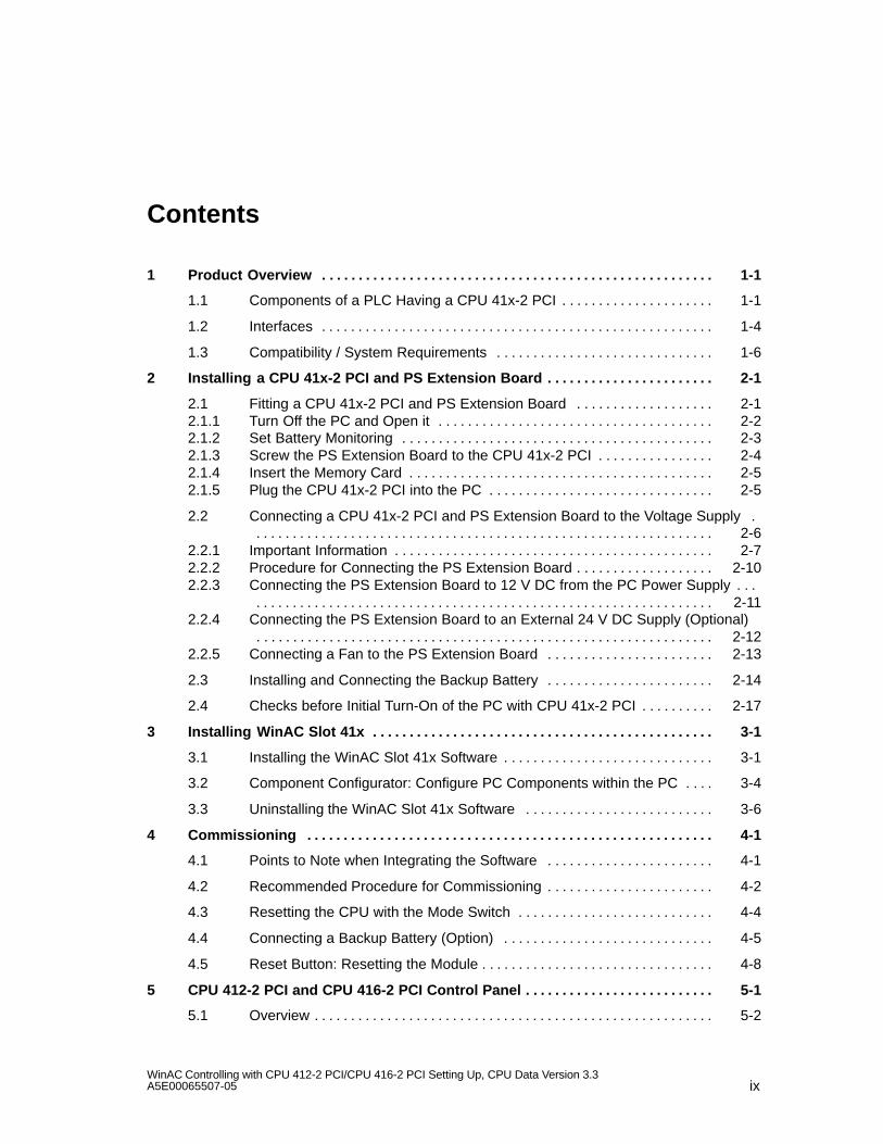
Contents
1 Product Overview 1-1. . . . . . . . . . . . . . . . . . . . . . . . . . . . . . . . . . . . . . . . . . . . . . . . . . . . . .
1.1 Components of a PLC Having a CPU 41x-2 PCI 1-1. . . . . . . . . . . . . . . . . . . . .
1.2 Interfaces 1-4. . . . . . . . . . . . . . . . . . . . . . . . . . . . . . . . . . . . . . . . . . . . . . . . . . . . . .
1.3 Compatibility / System Requirements 1-6. . . . . . . . . . . . . . . . . . . . . . . . . . . . . .
2 Installing a CPU 41x-2 PCI and PS Extension Board 2-1. . . . . . . . . . . . . . . . . . . . . . .
2.1 Fitting a CPU 41x-2 PCI and PS Extension Board 2-1. . . . . . . . . . . . . . . . . . . 2.1.1 Turn Off the PC and Open it 2-2. . . . . . . . . . . . . . . . . . . . . . . . . . . . . . . . . . . . . . 2.1.2 Set Battery Monitoring 2-3. . . . . . . . . . . . . . . . . . . . . . . . . . . . . . . . . . . . . . . . . . . 2.1.3 Screw the PS Extension Board to the CPU 41x-2 PCI 2-4. . . . . . . . . . . . . . . . 2.1.4 Insert the Memory Card 2-5. . . . . . . . . . . . . . . . . . . . . . . . . . . . . . . . . . . . . . . . . . 2.1.5 Plug the CPU 41x-2 PCI into the PC 2-5. . . . . . . . . . . . . . . . . . . . . . . . . . . . . . .
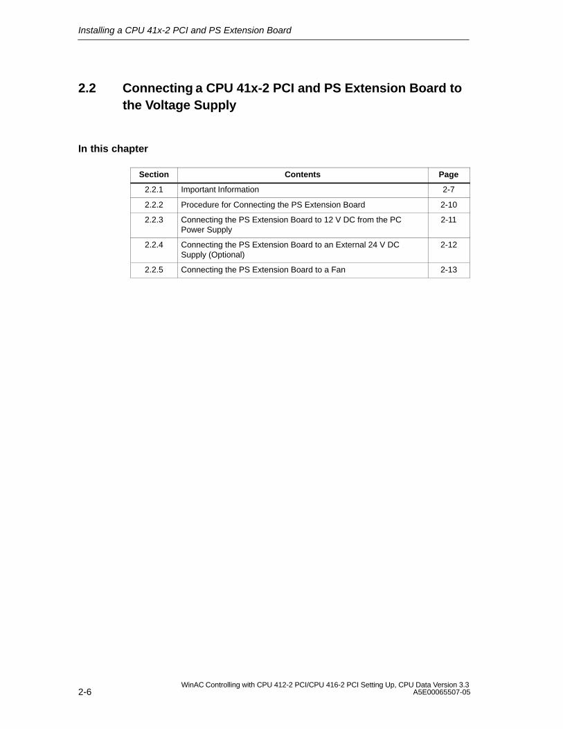
2.2 Connecting a CPU 41x-2 PCI and PS Extension Board to the Voltage Supply . 2-6. . . . . . . . . . . . . . . . . . . . . . . . . . . . . . . . . . . . . . . . . . . . . . . . . . . . . . . . . . . . . . .
2.2.1 Important Information 2-7. . . . . . . . . . . . . . . . . . . . . . . . . . . . . . . . . . . . . . . . . . . . 2.2.2 Procedure for Connecting the PS Extension Board 2-10. . . . . . . . . . . . . . . . . . . 2.2.3 Connecting the PS Extension Board to 12 V DC from the PC Power Supply . . .
2-11. . . . . . . . . . . . . . . . . . . . . . . . . . . . . . . . . . . . . . . . . . . . . . . . . . . . . . . . . . . . . . . 2.2.4 Connecting the PS Extension Board to an External 24 V DC Supply (Optional)
2-12. . . . . . . . . . . . . . . . . . . . . . . . . . . . . . . . . . . . . . . . . . . . . . . . . . . . . . . . . . . . . . . 2.2.5 Connecting a Fan to the PS Extension Board 2-13. . . . . . . . . . . . . . . . . . . . . . .
2.3 Installing and Connecting the Backup Battery 2-14. . . . . . . . . . . . . . . . . . . . . . .
2.4 Checks before Initial Turn-On of the PC with CPU 41x-2 PCI 2-17. . . . . . . . . .
3 Installing WinAC Slot 41x 3-1. . . . . . . . . . . . . . . . . . . . . . . . . . . . . . . . . . . . . . . . . . . . . . .
3.1 Installing the WinAC Slot 41x Software 3-1. . . . . . . . . . . . . . . . . . . . . . . . . . . . .
3.2 Component Configurator: Configure PC Components within the PC 3-4. . . .
3.3 Uninstalling the WinAC Slot 41x Software 3-6. . . . . . . . . . . . . . . . . . . . . . . . . .
4 Commissioning 4-1. . . . . . . . . . . . . . . . . . . . . . . . . . . . . . . . . . . . . . . . . . . . . . . . . . . . . . . .
4.1 Points to Note when Integrating the Software 4-1. . . . . . . . . . . . . . . . . . . . . . .
4.2 Recommended Procedure for Commissioning 4-2. . . . . . . . . . . . . . . . . . . . . . .
4.3 Resetting the CPU with the Mode Switch 4-4. . . . . . . . . . . . . . . . . . . . . . . . . . .
4.4 Connecting a Backup Battery (Option) 4-5. . . . . . . . . . . . . . . . . . . . . . . . . . . . .
4.5 Reset Button: Resetting the Module 4-8. . . . . . . . . . . . . . . . . . . . . . . . . . . . . . . .
5 CPU 412-2 PCI and CPU 416-2 PCI Control Panel 5-1. . . . . . . . . . . . . . . . . . . . . . . . . .
5.1 Overview 5-2. . . . . . . . . . . . . . . . . . . . . . . . . . . . . . . . . . . . . . . . . . . . . . . . . . . . . . .
Contents
xWinAC Controlling with CPU 412-2 PCI/CPU 416-2 PCI Setting Up, CPU Data Version 3.3
A5E00065507-05
5.2 Controls and Display Elements of CPU 41x-2 PCI 5-3. . . . . . . . . . . . . . . . . . .
5.3 Status and Error Indications 5-4. . . . . . . . . . . . . . . . . . . . . . . . . . . . . . . . . . . . . .
5.4 Operating Mode Controls 5-8. . . . . . . . . . . . . . . . . . . . . . . . . . . . . . . . . . . . . . . . . 5.4.1 Selecting the Startup Type 5-9. . . . . . . . . . . . . . . . . . . . . . . . . . . . . . . . . . . . . . . . 5.4.2 Protection Levels 5-10. . . . . . . . . . . . . . . . . . . . . . . . . . . . . . . . . . . . . . . . . . . . . . . .
5.5 Loading and Saving the STEP 7 User Program 5-11. . . . . . . . . . . . . . . . . . . . . . 5.5.1 A Few Explanations before Proceeding 5-11. . . . . . . . . . . . . . . . . . . . . . . . . . . . . 5.5.2 Saving and Loading the STEP 7 User Program 5-12. . . . . . . . . . . . . . . . . . . . . .
5.6 CPU 41x-2 PCI Controls on the Menu Bar 5-16. . . . . . . . . . . . . . . . . . . . . . . . . . 5.6.1 ”File” Menu 5-17. . . . . . . . . . . . . . . . . . . . . . . . . . . . . . . . . . . . . . . . . . . . . . . . . . . . . 5.6.2 ”CPU” Menu 5-18. . . . . . . . . . . . . . . . . . . . . . . . . . . . . . . . . . . . . . . . . . . . . . . . . . . . 5.6.3 ”Customize” Submenu 5-19. . . . . . . . . . . . . . . . . . . . . . . . . . . . . . . . . . . . . . . . . . . 5.6.4 ”Safety” Submenu 5-21. . . . . . . . . . . . . . . . . . . . . . . . . . . . . . . . . . . . . . . . . . . . . . . 5.6.5 “Connect CPU” Submenu 5-23. . . . . . . . . . . . . . . . . . . . . . . . . . . . . . . . . . . . . . . . 5.6.6 ”Help” Menu 5-23. . . . . . . . . . . . . . . . . . . . . . . . . . . . . . . . . . . . . . . . . . . . . . . . . . . .
6 CPU 41x-2 PCI as DP Master/DP Slave and Direct Data Exchange 6-1. . . . . . . . . .
6.1 DP Address Area of CPUs 41x-2 PCI 6-2. . . . . . . . . . . . . . . . . . . . . . . . . . . . . .
6.2 CPU 41x-2 PCI as DP Master 6-3. . . . . . . . . . . . . . . . . . . . . . . . . . . . . . . . . . . . .
6.3 Diagnostics of CPU 41x-2 PCI as DP master 6-6. . . . . . . . . . . . . . . . . . . . . . . .
6.4 CPU 41x-2 PCI as DP Slave 6-11. . . . . . . . . . . . . . . . . . . . . . . . . . . . . . . . . . . . . .
6.5 Diagnostics of CPU 41x-2 PCI as a DP Slave 6-16. . . . . . . . . . . . . . . . . . . . . . . 6.5.1 Diagnostics by Means of LED Displays 6-17. . . . . . . . . . . . . . . . . . . . . . . . . . . . . 6.5.2 Diagnostics with STEP 5 or STEP 7 6-18. . . . . . . . . . . . . . . . . . . . . . . . . . . . . . . 6.5.3 Reading out the Diagnostics 6-19. . . . . . . . . . . . . . . . . . . . . . . . . . . . . . . . . . . . . . 6.5.4 Structure of Slave Diagnostics 6-23. . . . . . . . . . . . . . . . . . . . . . . . . . . . . . . . . . . . 6.5.5 Station Status 1 to 3 6-24. . . . . . . . . . . . . . . . . . . . . . . . . . . . . . . . . . . . . . . . . . . . . 6.5.6 Master PROFIBUS Address 6-26. . . . . . . . . . . . . . . . . . . . . . . . . . . . . . . . . . . . . . 6.5.7 Manufacturer’s ID 6-26. . . . . . . . . . . . . . . . . . . . . . . . . . . . . . . . . . . . . . . . . . . . . . . 6.5.8 Identifier-Related Diagnostics 6-27. . . . . . . . . . . . . . . . . . . . . . . . . . . . . . . . . . . . . 6.5.9 Device-Related Diagnostics 6-28. . . . . . . . . . . . . . . . . . . . . . . . . . . . . . . . . . . . . . . 6.5.10 Interrupts 6-30. . . . . . . . . . . . . . . . . . . . . . . . . . . . . . . . . . . . . . . . . . . . . . . . . . . . . . .
6.6 Direct Data Exchange 6-31. . . . . . . . . . . . . . . . . . . . . . . . . . . . . . . . . . . . . . . . . . . .
6.7 Diagnostics During Direct Data Exchange 6-32. . . . . . . . . . . . . . . . . . . . . . . . . .
7 Time Synchronization (WinACTimeSync) 7-1. . . . . . . . . . . . . . . . . . . . . . . . . . . . . . . . .
7.1 Overview 7-2. . . . . . . . . . . . . . . . . . . . . . . . . . . . . . . . . . . . . . . . . . . . . . . . . . . . . . .
7.2 Assigning a CP to Time Synchronization 7-4. . . . . . . . . . . . . . . . . . . . . . . . . . . . 7.2.1 Setting the Access Point 7-5. . . . . . . . . . . . . . . . . . . . . . . . . . . . . . . . . . . . . . . . . 7.2.2 Installing an Interface 7-6. . . . . . . . . . . . . . . . . . . . . . . . . . . . . . . . . . . . . . . . . . . .
7.3 Using the Time Synchronization Service 7-8. . . . . . . . . . . . . . . . . . . . . . . . . . . . 7.3.1 Starting and Terminating Time Synchronization 7-8. . . . . . . . . . . . . . . . . . . . . . 7.3.2 Setting the Interval for Time Synchronization 7-9. . . . . . . . . . . . . . . . . . . . . . . .
7.4 User Example 7-10. . . . . . . . . . . . . . . . . . . . . . . . . . . . . . . . . . . . . . . . . . . . . . . . . . 7.4.1 Task: Communication Using Time Synchronization 7-10. . . . . . . . . . . . . . . . . . . 7.4.2 Component Configurator: Configure PC Components Within the PC 7-11. . . .
Contents
xiWinAC Controlling with CPU 412-2 PCI/CPU 416-2 PCI Setting Up, CPU Data Version 3.3A5E00065507-05
7.4.3 Commissioning wizard: assigning CP 5613 7-11. . . . . . . . . . . . . . . . . . . . . . . . . 7.4.4 Creating a Project 7-14. . . . . . . . . . . . . . . . . . . . . . . . . . . . . . . . . . . . . . . . . . . . . . . 7.4.5 Configuring an Access Point 7-23. . . . . . . . . . . . . . . . . . . . . . . . . . . . . . . . . . . . . . 7.4.6 Starting Time Synchronization 7-24. . . . . . . . . . . . . . . . . . . . . . . . . . . . . . . . . . . . .
8 CPU 412-2 PCI and CPU 416-2 PCI – Technical Specifications and Compatibility . . 8-1
8.1 Overview of the Parameters for the CPU 41x-2 PCI 8-2. . . . . . . . . . . . . . . . . .
8.2 Performance Features and Technical Specifications of the CPU 412-2 PCI . . . . 8-3. . . . . . . . . . . . . . . . . . . . . . . . . . . . . . . . . . . . . . . . . . . . . . . . . . . . . . . . . . . . . . .
8.3 Performance Features and Technical Specifications of the CPU 416-2 PCI . . . . 8-7. . . . . . . . . . . . . . . . . . . . . . . . . . . . . . . . . . . . . . . . . . . . . . . . . . . . . . . . . . . . . . .
8.4 Differences of CPU 41x-2 PCI from Previous Version (CPU 41x-2 PCI Version3.2) 8-11. . . . . . . . . . . . . . . . . . . . . . . . . . . . . . . . . . . . . . . . . . . . . . . . . . . . . . . . . . . .
9 PS Extension Board 9-1. . . . . . . . . . . . . . . . . . . . . . . . . . . . . . . . . . . . . . . . . . . . . . . . . . . .
10 Memory Cards 10-1. . . . . . . . . . . . . . . . . . . . . . . . . . . . . . . . . . . . . . . . . . . . . . . . . . . . . . . . . .
10.1 Design and Function 10-1. . . . . . . . . . . . . . . . . . . . . . . . . . . . . . . . . . . . . . . . . . . . .
10.2 Types of Memory Cards 10-2. . . . . . . . . . . . . . . . . . . . . . . . . . . . . . . . . . . . . . . . . .
A General Technical Specifications A-1. . . . . . . . . . . . . . . . . . . . . . . . . . . . . . . . . . . . . . . .
A.1 Standards, Certificates and Approvals A-1. . . . . . . . . . . . . . . . . . . . . . . . . . . . . .
A.2 Electromagnetic Compatibility A-3. . . . . . . . . . . . . . . . . . . . . . . . . . . . . . . . . . . . .
A.3 Shipping and Storage Conditions A-4. . . . . . . . . . . . . . . . . . . . . . . . . . . . . . . . . .
A.4 Mechanical and Climatic Environmental Conditions A-6. . . . . . . . . . . . . . . . . .
A.5 Certification for USA, Canada and Australia A-8. . . . . . . . . . . . . . . . . . . . . . . . .
B Networking B-1. . . . . . . . . . . . . . . . . . . . . . . . . . . . . . . . . . . . . . . . . . . . . . . . . . . . . . . . . . . .
B.1 Configuring an MPI or PROFIBUS Subnet B-1. . . . . . . . . . . . . . . . . . . . . . . . . . B.1.1 Network Operation B-1. . . . . . . . . . . . . . . . . . . . . . . . . . . . . . . . . . . . . . . . . . . . . . B.1.2 Fundamentals B-3. . . . . . . . . . . . . . . . . . . . . . . . . . . . . . . . . . . . . . . . . . . . . . . . . . B.1.3 Rules for Configuring a Subnet B-5. . . . . . . . . . . . . . . . . . . . . . . . . . . . . . . . . . . . B.1.4 Cable Lengths B-12. . . . . . . . . . . . . . . . . . . . . . . . . . . . . . . . . . . . . . . . . . . . . . . . . .
B.2 Network Components B-15. . . . . . . . . . . . . . . . . . . . . . . . . . . . . . . . . . . . . . . . . . . . B.2.1 PROFIBUS Bus Cable B-15. . . . . . . . . . . . . . . . . . . . . . . . . . . . . . . . . . . . . . . . . . . B.2.2 Bus Connector B-17. . . . . . . . . . . . . . . . . . . . . . . . . . . . . . . . . . . . . . . . . . . . . . . . . . B.2.3 Plugging the Bus Connector into Modules B-18. . . . . . . . . . . . . . . . . . . . . . . . . . B.2.4 RS 485 Repeater B-20. . . . . . . . . . . . . . . . . . . . . . . . . . . . . . . . . . . . . . . . . . . . . . . . B.2.5 RS 485 Repeater in Ungrounded and Grounded Mode B-22. . . . . . . . . . . . . . . B.2.6 Technical Specifications of the RS 485 Repeater B-24. . . . . . . . . . . . . . . . . . . .
B.3 Commissioning PROFIBUS-DP B-25. . . . . . . . . . . . . . . . . . . . . . . . . . . . . . . . . . .
C FAQs: Frequently Asked Questions about WinAC Slot 41x C-1. . . . . . . . . . . . . . . .
C.1 When do I use the PS extension board? C-2. . . . . . . . . . . . . . . . . . . . . . . . . . . .
C.2 Why does the battery supply not reside on the CPU 41x-2 PCI? C-2. . . . . . .
C.3 How can I make it without a PS extension board? C-3. . . . . . . . . . . . . . . . . . . .
Contents
xiiWinAC Controlling with CPU 412-2 PCI/CPU 416-2 PCI Setting Up, CPU Data Version 3.3
A5E00065507-05
C.4 How can I save user data without a PS extension board when powering downand up? C-4. . . . . . . . . . . . . . . . . . . . . . . . . . . . . . . . . . . . . . . . . . . . . . . . . . . . . . . .
C.5 Why do I still have to connect the PS extension board to the power supply ofthe PC (Y-cable)? C-4. . . . . . . . . . . . . . . . . . . . . . . . . . . . . . . . . . . . . . . . . . . . . . .
C.6 When do I use a FLASH card and when a RAM card? C-5. . . . . . . . . . . . . . . .
C.7 Is operation possible without a memory card? C-5. . . . . . . . . . . . . . . . . . . . . . .
C.8 Can WinAC Slot 41x also be operated as a DP slave? C-6. . . . . . . . . . . . . . . .
C.9 Does the PROFIBUS-DP interface integrated on the CPU 41x-2 PCI supportthe DP services (SFC58/59)? C-6. . . . . . . . . . . . . . . . . . . . . . . . . . . . . . . . . . . . .
C.10 Does WinAC Slot 41x support network routing? C-6. . . . . . . . . . . . . . . . . . . . .
C.11 Do I have to use another S7 driver to use the integrated Industrial Ethernetinterface of the SIMATIC PC? C-7. . . . . . . . . . . . . . . . . . . . . . . . . . . . . . . . . . . . .
C.12 What are the advantages of using PCI? C-7. . . . . . . . . . . . . . . . . . . . . . . . . . . .
C.13 How can PC applications access the process data of WinAC Slot 41x? C-7.
C.14 What are the advantages of using WinAC Slot 41x together with a SIMATICBox PC 620? C-8. . . . . . . . . . . . . . . . . . . . . . . . . . . . . . . . . . . . . . . . . . . . . . . . . . .
D Panel Control D-1. . . . . . . . . . . . . . . . . . . . . . . . . . . . . . . . . . . . . . . . . . . . . . . . . . . . . . . . . .
D.1 Accessing the CPU 41x-2 PCI with the Panel Control D-2. . . . . . . . . . . . . . . .
D.2 Selecting the Control Engine for the Panel Control D-5. . . . . . . . . . . . . . . . . . .
D.3 Sample Programs Using the Panel Control D-6. . . . . . . . . . . . . . . . . . . . . . . . . .
D.4 Evaluating the LED Indications of the Panel Control D-10. . . . . . . . . . . . . . . . . .
D.5 Properties and Methods of the Panel Control D-11. . . . . . . . . . . . . . . . . . . . . . . .
D.6 Events of the Panel Control D-22. . . . . . . . . . . . . . . . . . . . . . . . . . . . . . . . . . . . . . .
E Spare Parts and Accessories – Order Numbers E-1. . . . . . . . . . . . . . . . . . . . . . . . . . .
F Guidelines for Handling Electrostatic Sensitive Devices (ESD) F-1. . . . . . . . . . . . .
F.1 What are ESDs? F-2. . . . . . . . . . . . . . . . . . . . . . . . . . . . . . . . . . . . . . . . . . . . . . . .
F.2 Electrostatic Charging of Persons F-3. . . . . . . . . . . . . . . . . . . . . . . . . . . . . . . . .
F.3 General Protective Measures Against Electrostatic Discharge Damage F-4.
G List of Abbreviations G-1. . . . . . . . . . . . . . . . . . . . . . . . . . . . . . . . . . . . . . . . . . . . . . . . . . .
Glossary Glossary-1. . . . . . . . . . . . . . . . . . . . . . . . . . . . . . . . . . . . . . . . . . . . . . . . . . . . . . . . . . .
Index Index-1. . . . . . . . . . . . . . . . . . . . . . . . . . . . . . . . . . . . . . . . . . . . . . . . . . . . . . . . . . . . . . . . .
Contents
xiiiWinAC Controlling with CPU 412-2 PCI/CPU 416-2 PCI Setting Up, CPU Data Version 3.3A5E00065507-05
Figures
1-1 Components of a PLC Having a CPU 41x-2 PCI 1-1. . . . . . . . . . . . . . . . . . . . . 1-2 CPU 41x-2 PCI 1-4. . . . . . . . . . . . . . . . . . . . . . . . . . . . . . . . . . . . . . . . . . . . . . . . . 1-3 PS Extension Board 1-6. . . . . . . . . . . . . . . . . . . . . . . . . . . . . . . . . . . . . . . . . . . . . 2-1 Position of the Switch on CPU 41x-2 PCI 2-3. . . . . . . . . . . . . . . . . . . . . . . . . . . 2-2 Screwing the CPU 41x-2 PCI to the PS Extension Board 2-4. . . . . . . . . . . . . 2-3 Inserting a Memory Card in a CPU 2-5. . . . . . . . . . . . . . . . . . . . . . . . . . . . . . . . . 2-4 Position of Cable Connectors on PS Extension Board 2-10. . . . . . . . . . . . . . . . 2-5 Box PC 620/Panel PC 760: Connectors for Connection to 12 V DC
from PC Power Supply 2-11. . . . . . . . . . . . . . . . . . . . . . . . . . . . . . . . . . . . . . . . . . . 2-6 Slot Plate with Hood 2-14. . . . . . . . . . . . . . . . . . . . . . . . . . . . . . . . . . . . . . . . . . . . . 2-7 Plate for Battery Holder on PC Housing 2-15. . . . . . . . . . . . . . . . . . . . . . . . . . . . 2-8 Interfaces 2-15. . . . . . . . . . . . . . . . . . . . . . . . . . . . . . . . . . . . . . . . . . . . . . . . . . . . . . 2-9 2-Pin 4.95 mm Coaxial Connector to Backup Battery 2-16. . . . . . . . . . . . . . . . . 3-1 Installing the Components of WinAC Slot 41xx 3-3. . . . . . . . . . . . . . . . . . . . . . 4-1 CPU > FMR Menu Option 4-7. . . . . . . . . . . . . . . . . . . . . . . . . . . . . . . . . . . . . . . . 5-1 CPU 41x-2 PCI Control Panel 5-2. . . . . . . . . . . . . . . . . . . . . . . . . . . . . . . . . . . . . 5-2 Controls and Display Elements of CPU 41x-2 PCI on the Control Panel 5-3. 5-3 Selecting the Startup Type 5-9. . . . . . . . . . . . . . . . . . . . . . . . . . . . . . . . . . . . . . . . 5-4 Loading the STEP 7 User Program into the Memory of CPU 41x-2 PCI 5-11. 5-5 Archiving 5-13. . . . . . . . . . . . . . . . . . . . . . . . . . . . . . . . . . . . . . . . . . . . . . . . . . . . . . . 5-6 Restoring 5-14. . . . . . . . . . . . . . . . . . . . . . . . . . . . . . . . . . . . . . . . . . . . . . . . . . . . . . 5-7 Autoload 5-15. . . . . . . . . . . . . . . . . . . . . . . . . . . . . . . . . . . . . . . . . . . . . . . . . . . . . . . 5-8 ”File” Menu 5-17. . . . . . . . . . . . . . . . . . . . . . . . . . . . . . . . . . . . . . . . . . . . . . . . . . . . . 5-9 ”CPU” Menu 5-18. . . . . . . . . . . . . . . . . . . . . . . . . . . . . . . . . . . . . . . . . . . . . . . . . . . . 5-10 ”General” Tab 5-19. . . . . . . . . . . . . . . . . . . . . . . . . . . . . . . . . . . . . . . . . . . . . . . . . . . 5-11 ”Language” Tab 5-20. . . . . . . . . . . . . . . . . . . . . . . . . . . . . . . . . . . . . . . . . . . . . . . . . 5-12 ”Autoload” Tab 5-21. . . . . . . . . . . . . . . . . . . . . . . . . . . . . . . . . . . . . . . . . . . . . . . . . . 5-13 ”Access Rights” Dialog Box 5-21. . . . . . . . . . . . . . . . . . . . . . . . . . . . . . . . . . . . . . . 5-14 ”Access Verification” Dialog Box 5-22. . . . . . . . . . . . . . . . . . . . . . . . . . . . . . . . . . . 5-15 ”Change Password” Dialog Box 5-22. . . . . . . . . . . . . . . . . . . . . . . . . . . . . . . . . . . 5-16 ”Help” Menu 5-23. . . . . . . . . . . . . . . . . . . . . . . . . . . . . . . . . . . . . . . . . . . . . . . . . . . . 6-1 Diagnostics with CPU 41x-2 PCI 6-8. . . . . . . . . . . . . . . . . . . . . . . . . . . . . . . . . . 6-2 Diagnostics Addresses for DP Master and DP Slave 6-9. . . . . . . . . . . . . . . . . 6-3 Transfer Memory in the CPU 41x-2 PCI as DP Slave 6-12. . . . . . . . . . . . . . . . . 6-4 Diagnostics Addresses for DP Master and DP Slave 6-21. . . . . . . . . . . . . . . . . 6-5 Structure of Slave Diagnostics 6-23. . . . . . . . . . . . . . . . . . . . . . . . . . . . . . . . . . . . 6-6 Structure of Identifier-Related Diagnostics of CPU 41x-2 PCI 6-27. . . . . . . . . . 6-7 Structure of Device-Related Diagnostics 6-28. . . . . . . . . . . . . . . . . . . . . . . . . . . . 6-8 Bytes x +4 to x +7 for Diagnostic and Process Interrupts 6-29. . . . . . . . . . . . . . 6-9 Direct Data Exchange with CPUs 41x-2 PCI 6-31. . . . . . . . . . . . . . . . . . . . . . . . 6-10 Diagnostics Address for the Receiver During Direct Data Exchange 6-32. . . . 7-1 Clock Synchronization 7-2. . . . . . . . . . . . . . . . . . . . . . . . . . . . . . . . . . . . . . . . . . . 7-2 Configuring the Interfaces 7-4. . . . . . . . . . . . . . . . . . . . . . . . . . . . . . . . . . . . . . . . 7-3 Setting the PG/PC Interface 7-5. . . . . . . . . . . . . . . . . . . . . . . . . . . . . . . . . . . . . . 7-4 Installing/Uninstalling Interfaces 7-7. . . . . . . . . . . . . . . . . . . . . . . . . . . . . . . . . . . 7-5 Starting/Exiting Time Synchronization 7-8. . . . . . . . . . . . . . . . . . . . . . . . . . . . . 7-6 Setting the Period for Time Synchronization 7-9. . . . . . . . . . . . . . . . . . . . . . . . . 7-7 Communication Using Time Synchronization 7-10. . . . . . . . . . . . . . . . . . . . . . . . 7-8 Component Configurator: Assigning Station Names 7-11. . . . . . . . . . . . . . . . . . 7-9 Commissioning wizard: settings for CP 5613 7-13. . . . . . . . . . . . . . . . . . . . . . . . 7-10 Creating a Project 7-14. . . . . . . . . . . . . . . . . . . . . . . . . . . . . . . . . . . . . . . . . . . . . . .
Contents
xivWinAC Controlling with CPU 412-2 PCI/CPU 416-2 PCI Setting Up, CPU Data Version 3.3
A5E00065507-05
7-11 Selecting a Mounting Rack 7-15. . . . . . . . . . . . . . . . . . . . . . . . . . . . . . . . . . . . . . . 7-12 CP 5613: Properties 7-16. . . . . . . . . . . . . . . . . . . . . . . . . . . . . . . . . . . . . . . . . . . . . 7-13 Configuring the Hardware of the S7-400 Station 7-17. . . . . . . . . . . . . . . . . . . . . 7-14 Bus Connection 7-19. . . . . . . . . . . . . . . . . . . . . . . . . . . . . . . . . . . . . . . . . . . . . . . . . 7-15 Enabling Time Synchronization 7-20. . . . . . . . . . . . . . . . . . . . . . . . . . . . . . . . . . . . 7-16 Setting a Period 7-21. . . . . . . . . . . . . . . . . . . . . . . . . . . . . . . . . . . . . . . . . . . . . . . . 7-17 Setting the Synchronization Mode 7-22. . . . . . . . . . . . . . . . . . . . . . . . . . . . . . . . . 7-18 Setting the PG/PC Interface 7-23. . . . . . . . . . . . . . . . . . . . . . . . . . . . . . . . . . . . . . 9-1 PS Extension Board 9-2. . . . . . . . . . . . . . . . . . . . . . . . . . . . . . . . . . . . . . . . . . . . . 10-1 Memory Card 10-1. . . . . . . . . . . . . . . . . . . . . . . . . . . . . . . . . . . . . . . . . . . . . . . . . . . B-1 Bus Connector: Terminating Resistor Connected and Switched Off B-7. . . . . B-2 The Terminating Resistor on the RS 485 Repeater B-7. . . . . . . . . . . . . . . . . . . B-3 Connecting Terminating Resistors on an MPI subnet B-8. . . . . . . . . . . . . . . . . B-4 Example of an MPI Subnet B-9. . . . . . . . . . . . . . . . . . . . . . . . . . . . . . . . . . . . . . . B-5 Example of a PROFIBUS Subnet B-10. . . . . . . . . . . . . . . . . . . . . . . . . . . . . . . . . . B-6 Example of a Configuration with the CPU 41x-2 DP in an MPI and PROFIBUS
Subnet B-11. . . . . . . . . . . . . . . . . . . . . . . . . . . . . . . . . . . . . . . . . . . . . . . . . . . . . . . . . B-7 Cable Lengths in an MPI Subnet B-14. . . . . . . . . . . . . . . . . . . . . . . . . . . . . . . . . . B-8 Straight Bus Connector B-17. . . . . . . . . . . . . . . . . . . . . . . . . . . . . . . . . . . . . . . . . . B-9 Stripping Length for Connecting to the Bus Connector (6GK1 500-0EA02) B-18B-10 Connecting the Bus Cable to the Bus Connector B-19. . . . . . . . . . . . . . . . . . . . . B-11 Connecting/Disconnecting the Terminating Resistor B-19. . . . . . . . . . . . . . . . . . B-12 Preparing the PROFIBUS Bus Cable B-22. . . . . . . . . . . . . . . . . . . . . . . . . . . . . . . B-13 Optical Isolation B-23. . . . . . . . . . . . . . . . . . . . . . . . . . . . . . . . . . . . . . . . . . . . . . . . . D-1 Buttons and Indicators on the Panel Control D-2. . . . . . . . . . . . . . . . . . . . . . . . D-2 Panel Control Properties (General Tab) D-5. . . . . . . . . . . . . . . . . . . . . . . . . . . . . F-1 Electrostatic Voltages which Can Build Up on a Person F-3. . . . . . . . . . . . . . .
Tables
1-1 Components of a PLC Having a PC and a CPU 41x-2 PCI 1-2. . . . . . . . . . . . 1-2 Compatibility / System Requirements 1-7. . . . . . . . . . . . . . . . . . . . . . . . . . . . . . 1-3 Supported operating systems 1-8. . . . . . . . . . . . . . . . . . . . . . . . . . . . . . . . . . . . . 2-1 Procedure for Fitting the CPU 41x-2 PCI and the PS Extension Board 2-1. 2-2 Setting the Switch to Inhibit Battery Monitoring 2-3. . . . . . . . . . . . . . . . . . . . . . 2-3 What Happens after Power Up and Power Down of the PC? (without Autoload)
2-8. . . . . . . . . . . . . . . . . . . . . . . . . . . . . . . . . . . . . . . . . . . . . . . . . . . . . . . . . . . . . . . 2-4 When Are the Warm Restart (Restart) and Autoload Functions Possible? 2-92-5 Procedure for Connecting the PS Extension Board 2-10. . . . . . . . . . . . . . . . . . . 2-6 Terminal Assignment of the External 24 V DC Supply 2-13. . . . . . . . . . . . . . . . 2-7 Connector Pin Assignment (Backup Battery) 2-16. . . . . . . . . . . . . . . . . . . . . . . 2-8 Check List for Checks before Turning on the PC for the First Time 2-17. . . . . 4-1 Validity of the MPI Parameters Following a Memory Reset 4-5. . . . . . . . . . . . 5-1 LED Displays on the Control Panel 5-4. . . . . . . . . . . . . . . . . . . . . . . . . . . . . . . . 5-2 Status Displays 5-5. . . . . . . . . . . . . . . . . . . . . . . . . . . . . . . . . . . . . . . . . . . . . . . . . 5-3 Error Displays and Special Events 5-5. . . . . . . . . . . . . . . . . . . . . . . . . . . . . . . . . 5-4 Operation of the Controls 5-8. . . . . . . . . . . . . . . . . . . . . . . . . . . . . . . . . . . . . . . . 5-5 Startup Types for CPU 41x-2 PCI 5-9. . . . . . . . . . . . . . . . . . . . . . . . . . . . . . . . . 5-6 CPU 41x-2 PCI Protection Levels 5-10. . . . . . . . . . . . . . . . . . . . . . . . . . . . . . . . . . 6-1 CPUs 41x-2 PCI (MPI/DP Interface as PROFIBUS-DP) 6-2. . . . . . . . . . . . . . 6-2 Meaning of ”BUSF” LED of CPU 41x-2 PCI as DP Master 6-6. . . . . . . . . . . . 6-3 Reading Out the Diagnostics in STEP 7 6-7. . . . . . . . . . . . . . . . . . . . . . . . . . . .
Contents
xvWinAC Controlling with CPU 412-2 PCI/CPU 416-2 PCI Setting Up, CPU Data Version 3.3A5E00065507-05
6-4 Event Detection of CPUs 41x-2 PCI as DP Master 6-10. . . . . . . . . . . . . . . . . . 6-5 Analysis of RUN/STOP Transitions in the DP Master/DP Slave 6-10. . . . . . . 6-6 Configuration Example for the Address Areas of the Transfer Memory 6-13. 6-7 Meaning of the ”BUSF” LEDs of CPU 41x-2 PCI as DP Slave 6-17. . . . . . . . . 6-8 Reading Out the Diagnostics in STEP 5 and STEP 7 in the Master System . . .
6-19. . . . . . . . . . . . . . . . . . . . . . . . . . . . . . . . . . . . . . . . . . . . . . . . . . . . . . . . . . . . . . 6-9 Event Detection of CPUs 41x-2 PCI as DP Slave 6-22. . . . . . . . . . . . . . . . . . . 6-10 Analysis of RUN/STOP Transitions in the DP Master/DP Slave 6-22. . . . . . . 6-11 Structure of Station Status 1 (Byte 0) 6-24. . . . . . . . . . . . . . . . . . . . . . . . . . . . . . 6-12 Structure of Station Status 2 (Byte 1) 6-25. . . . . . . . . . . . . . . . . . . . . . . . . . . . . . 6-13 Structure of Station Status 3 (Byte 2) 6-25. . . . . . . . . . . . . . . . . . . . . . . . . . . . . . 6-14 Structure of the Master PROFIBUS Address (Byte 3) 6-26. . . . . . . . . . . . . . . . 6-15 Structure of the Manufacturer’s ID (Bytes 4, 5) 6-26. . . . . . . . . . . . . . . . . . . . . . 6-16 Event Detection of CPUs 41x-2 PCI as Receivers During Direct Data Exchange
6-32. . . . . . . . . . . . . . . . . . . . . . . . . . . . . . . . . . . . . . . . . . . . . . . . . . . . . . . . . . . . . . . 6-17 Analysis of a Station Failure of the Sender During Direct Data Exchange 6-3310-1 Differences Between RAM Card and FLASH Card 10-3. . . . . . . . . . . . . . . . . . . B-1 Permissible Cable Lengths in an MPI Subnet Segment B-12. . . . . . . . . . . . . . . B-2 Permissible Cable Lengths in a PROFIBUS Subnet Depending on the
Transmission Rate B-12. . . . . . . . . . . . . . . . . . . . . . . . . . . . . . . . . . . . . . . . . . . . . . B-3 Lengths of Spur Lines per Segment B-13. . . . . . . . . . . . . . . . . . . . . . . . . . . . . . . . B-4 Network Components B-15. . . . . . . . . . . . . . . . . . . . . . . . . . . . . . . . . . . . . . . . . . . B-5 Properties of the PROFIBUS Bus Cable B-16. . . . . . . . . . . . . . . . . . . . . . . . . . . . B-6 Specifications for Installation of Indoor Bus Cable B-16. . . . . . . . . . . . . . . . . . . . D-1 Buttons for Changing the CPU 41x-2 PCI Operating Mode D-3. . . . . . . . . . . . D-2 LED Displays D-4. . . . . . . . . . . . . . . . . . . . . . . . . . . . . . . . . . . . . . . . . . . . . . . . . . D-3 Connecting a CPU 41x-2 PCI and Changing the Operating Mode D-6. . . . . . D-4 Configuring the Security State for the Panel Control D-8. . . . . . . . . . . . . . . . . D-5 Responding to Changes in the State of the LED Displays on the Panel Control
D-9. . . . . . . . . . . . . . . . . . . . . . . . . . . . . . . . . . . . . . . . . . . . . . . . . . . . . . . . . . . . . . D-6 Masks for the Panel Control LED Displays D-10. . . . . . . . . . . . . . . . . . . . . . . . .

Contents
xviWinAC Controlling with CPU 412-2 PCI/CPU 416-2 PCI Setting Up, CPU Data Version 3.3
A5E00065507-05
1-1WinAC Controlling with CPU 412-2 PCI/CPU 416-2 PCI Setting Up, CPU Data Version 3.3A5E00065507-05
Product Overview
In this chapter
Section Contents Page
1.1 Components of a PLC Having a CPU 41x-2 PCI 1-1
1.2 Interfaces 1-4
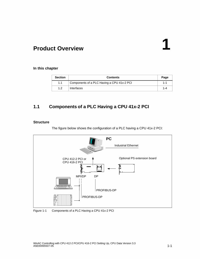
1.1 Components of a PLC Having a CPU 41x-2 PCI
Structure
The figure below shows the configuration of a PLC having a CPU 41x-2 PCI:
PROFIBUS-DP
PC
CPU 412-2 PCI orCPU 416-2 PCI
Optional PS extension board
DP
Industrial Ethernet
MPI/DP
PROFIBUS-DP
Figure 1-1 Components of a PLC Having a CPU 41x-2 PCI
1
Product Overview
1-2WinAC Controlling with CPU 412-2 PCI/CPU 416-2 PCI Setting Up, CPU Data Version 3.3
A5E00065507-05
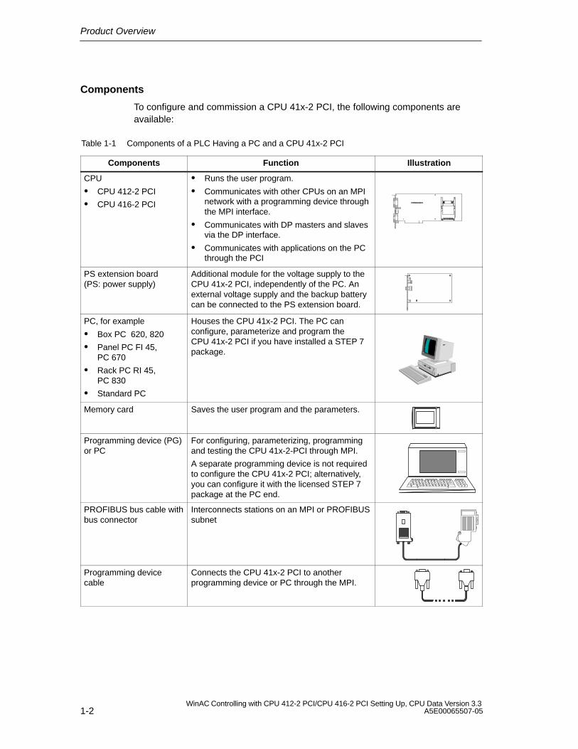
Components
To configure and commission a CPU 41x-2 PCI, the following components areavailable:
Table 1-1 Components of a PLC Having a PC and a CPU 41x-2 PCI
Components Function Illustration
CPU
CPU 412-2 PCI
CPU 416-2 PCI
Runs the user program.
Communicates with other CPUs on an MPInetwork with a programming device throughthe MPI interface.
Communicates with DP masters and slavesvia the DP interface.
Communicates with applications on the PCthrough the PCI
PS extension board(PS: power supply)
Additional module for the voltage supply to theCPU 41x-2 PCI, independently of the PC. Anexternal voltage supply and the backup batterycan be connected to the PS extension board.
PC, for example
Box PC 620, 820
Panel PC FI 45,PC 670
Rack PC RI 45,PC 830
Standard PC
Houses the CPU 41x-2 PCI. The PC canconfigure, parameterize and program theCPU 41x-2 PCI if you have installed a STEP 7package.
Memory card Saves the user program and the parameters.
Programming device (PG)or PC
For configuring, parameterizing, programmingand testing the CPU 41x-2-PCI through MPI.
A separate programming device is not requiredto configure the CPU 41x-2 PCI; alternatively,you can configure it with the licensed STEP 7package at the PC end.
PROFIBUS bus cable withbus connector
Interconnects stations on an MPI or PROFIBUSsubnet
Programming devicecable
Connects the CPU 41x-2 PCI to anotherprogramming device or PC through the MPI.
Product Overview
1-3WinAC Controlling with CPU 412-2 PCI/CPU 416-2 PCI Setting Up, CPU Data Version 3.3A5E00065507-05
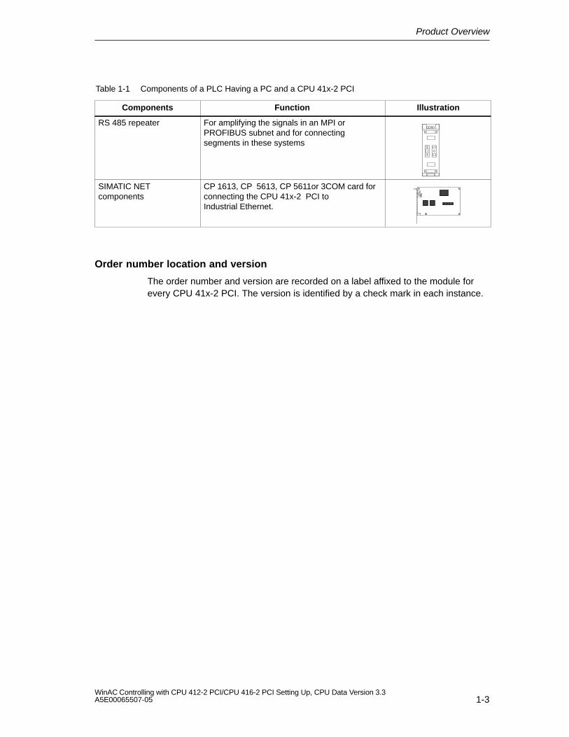
Table 1-1 Components of a PLC Having a PC and a CPU 41x-2 PCI
Components IllustrationFunction
RS 485 repeater For amplifying the signals in an MPI orPROFIBUS subnet and for connectingsegments in these systems
SIMATIC NETcomponents
CP 1613, CP 5613, CP 5611or 3COM card forconnecting the CPU 41x-2 PCI toIndustrial Ethernet.
Order number location and version
The order number and version are recorded on a label affixed to the module forevery CPU 41x-2 PCI. The version is identified by a check mark in each instance.
Product Overview
1-4WinAC Controlling with CPU 412-2 PCI/CPU 416-2 PCI Setting Up, CPU Data Version 3.3
A5E00065507-05
1.2 Interfaces
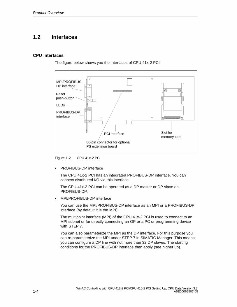
CPU interfaces
The figure below shows you the interfaces of CPU 41x-2 PCI:
PCI interface
80-pin connector for optionalPS extension board
Slot formemory card
MPI/PROFIBUS-DP interface
Resetpush-button
LEDs
PROFIBUS-DPinterface
Figure 1-2 CPU 41x-2 PCI
PROFIBUS-DP interface
The CPU 41x-2 PCI has an integrated PROFIBUS-DP interface. You canconnect distributed I/O via this interface.
The CPU 41x-2 PCI can be operated as a DP master or DP slave onPROFIBUS-DP.
MPI/PROFIBUS-DP interface
You can use the MPI/PROFIBUS-DP interface as an MPI or a PROFIBUS-DPinterface (by default it is the MPI).
The multipoint interface (MPI) of the CPU 41x-2 PCI is used to connect to anMPI subnet or for directly connecting an OP or a PC or programming devicewith STEP 7.
You can also parameterize the MPI as the DP interface. For this purpose youcan re-parameterize the MPI under STEP 7 in SIMATIC Manager. This meansyou can configure a DP line with not more than 32 DP slaves. The startingconditions for the PROFIBUS-DP interface then apply (see higher up).
Product Overview
1-5WinAC Controlling with CPU 412-2 PCI/CPU 416-2 PCI Setting Up, CPU Data Version 3.3A5E00065507-05
Note
At the MPI/PROFIBUS-DP interface, pin 7 does not have 24 V for supplying, say,operator panels or remote servicing adapters.
Slot for memory card
You can insert a memory card in this slot on the CPU 41x-2 PCI. You will find amore detailed description of memory cards in Chapter 10.
LEDs on the slot plate
Located on the slot plate of CPU 41x-2 PCI are LEDs, in addition to the LEDindications on the control panel. The meaning of the LEDs is explained insection 5.3.
– R (RUN)
– S (STOP)
– SF (INTF, EXTF)
– BF (BUSF1, BUSF2)
Product Overview
1-6WinAC Controlling with CPU 412-2 PCI/CPU 416-2 PCI Setting Up, CPU Data Version 3.3
A5E00065507-05
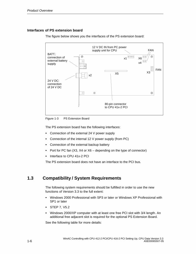
Interfaces of PS extension board
The figure below shows you the interfaces of the PS extension board:
24 V DC: connectionof 24 V DC
BATT.:connection of external batterysupply
12 V DC IN from PC powersupply unit for CPU
FAN
FAN
x2
x1
X5
X6
x4
80-pin connectorto CPU 41x-2 PCI
X3
Figure 1-3 PS Extension Board
The PS extension board has the following interfaces:
Connection of the external 24 V power supply
Connection of the internal 12 V power supply (from PC)
Connection of the external backup battery
Port for PC fan (X3, X4 or X6 – depending on the type of connector)
Interface to CPU 41x-2 PCI
The PS extension board does not have an interface to the PCI bus.
1.3 Compatibility / System Requirements
The following system requirements should be fulfilled in order to use the newfunctions of Version 3.3 to the full extent:
Windows 2000 Professional with SP3 or later or Windows XP Professional withSP1 or later
STEP 7, V5.2
Windows 2000/XP computer with at least one free PCI slot with 3/4 length. Anadditional free adjacent slot is required for the optional PS Extension Board.
See the following table for more details:
Product Overview
1-7WinAC Controlling with CPU 412-2 PCI/CPU 416-2 PCI Setting Up, CPU Data Version 3.3A5E00065507-05
Table 1-2 Compatibility / System Requirements
Used together with WinAC Slot412/416, V3.1
CPU 41x-2 PCI Firmware 1.1.0
PC softwareversion 3.1
WinAC Slot412/416, V3.2
CPU 41x-2 PCIFirmware 3.0PC softwareversion 3.2
WinAC Slot412/416, V3.3 (new)
CPU 41x-2 PCIFirmware 3.1PC softwareversion 3.3
STEP 7 V5.1, <SP2 YES Configuration YES!No communicationwith SIMATIC NETCP’s, No AdvancedPC Configuration 1)
Configuration YES!No communicationwith SIMATIC NETCP’s, No AdvancedPC Configuration 1)
V5.1, SP2or later
YES YES YES, the new func-tions of the firmwareV3.1 are not sup-ported, however
V5.2 or later YES YES YES
Operation withSIMATIC NETcomponents
SIMATIC NETCD edition 05/00
YES Upgrade to WinAC Slot 41x,V3.1+SP1 required,No new firmware,PC software only
NO
SIMATIC NETCD 07/01 + SP5
NOUpgrade to WinACSlot 41x, V3.2OR use ofSIMATIC NET CD05/00 (see above)
YES YES
Windows 2000 only!
SIMATIC NETCD 11/02
NO NO YES
Windows XP only!
Microsoft Windows NT4 Workstation SP6
YES YES NO
Microsoft Windows 2000 Professional SP3
NO YES YES
Microsoft Windows XP Professional SP1
NO NO YES
SPARE PART CPU 41x-2 PCI, Firmware 3.1
YES YES YES
Support for WinAC Slot T–Kit, V3.3
NO YES YES
1) Advanced PC Configuration: Configuration of the PC as runtime station.
The configuration of WinAC Slot 412/416 V3.2 can be carried over to WinAC Slot412/416 V3.3 without restrictions.
In order to use the new functions of WinAC Slot 412/416 V3.3, the new firmwareCPU 41x-2 PCI, V3.1 has to be copied from the hardware catalog.
Product Overview
1-8WinAC Controlling with CPU 412-2 PCI/CPU 416-2 PCI Setting Up, CPU Data Version 3.3
A5E00065507-05
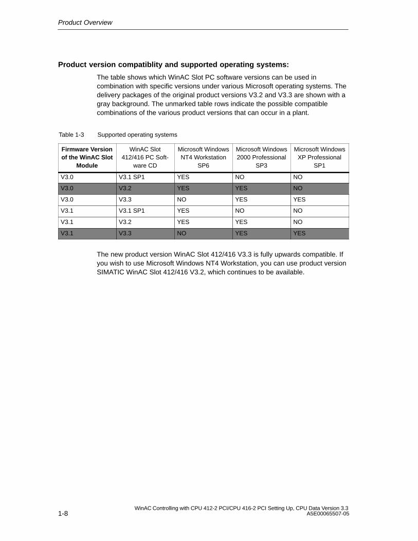
Product version compatiblity and supported operating systems:
The table shows which WinAC Slot PC software versions can be used incombination with specific versions under various Microsoft operating systems. Thedelivery packages of the original product versions V3.2 and V3.3 are shown with agray background. The unmarked table rows indicate the possible compatiblecombinations of the various product versions that can occur in a plant.
Table 1-3 Supported operating systems
Firmware Versionof the WinAC Slot
Module
WinAC Slot412/416 PC Soft-
ware CD
Microsoft WindowsNT4 Workstation
SP6
Microsoft Windows2000 Professional
SP3
Microsoft WindowsXP Professional
SP1
V3.0 V3.1 SP1 YES NO NO
V3.0 V3.2 YES YES NO
V3.0 V3.3 NO YES YES
V3.1 V3.1 SP1 YES NO NO
V3.1 V3.2 YES YES NO
V3.1 V3.3 NO YES YES
The new product version WinAC Slot 412/416 V3.3 is fully upwards compatible. Ifyou wish to use Microsoft Windows NT4 Workstation, you can use product versionSIMATIC WinAC Slot 412/416 V3.2, which continues to be available.
2-1WinAC Controlling with CPU 412-2 PCI/CPU 416-2 PCI Setting Up, CPU Data Version 3.3A5E00065507-05
Installing a CPU 41x-2 PCI andPS Extension Board
In this chapter
This chapter describes how you install a CPU 41x-2 PCI and the PS extensionboard on a PC.
Section Contents Page
2.1 Fitting a CPU 41x-2 PCI and PS Extension Board 2-1
2.2 Connecting a CPU 41x-2 PCI and PS Extension Board to theVoltage Supply
2-6
2.3 Installing and Connecting the Backup Battery 2-14
2.4 Checks Before Initial Turn-on of the PC with CPU 41x-2 PCI 2-17
2.1 Fitting a CPU 41x-2 PCI and PS Extension Board
Procedure
The following table shows you the basic procedure for fitting the CPU 41x-2 PCIand PS extension board.
Table 2-1 Procedure for Fitting the CPU 41x-2 PCI and thePS Extension Board
Step Procedure Refer toSection...
1. Turn Off the PC and Open it 2.1.1
2. Set Battery Monitoring 2.1.2
3. Screw the PS Extension Board to the CPU 41x-2 PCI 2.1.3
4. Insert the Memory Card 2.1.4
5. Plug the CPU 41x-2 PCI into the PC 2.1.5
2
Installing a CPU 41x-2 PCI and PS Extension Board
2-2WinAC Controlling with CPU 412-2 PCI/CPU 416-2 PCI Setting Up, CPU Data Version 3.3
A5E00065507-05
Requirements
Please note the following requirements before you install the CPU 41x-2 PCI andthe PS extension board.
The CPU 41x-2 PCI requires a PCI slot at the default distance.
If you use the CPU 41x-2 PCI together with a PS extension board, you willrequire two adjacent vacant slots, the PS extension board not being connectedto the PCI bus.
Note
Some PCs with PCI/ISA combi slots have their housing cutouts on the slot platefor ISA plug-in cards. If you use the CPU 41x-2 PCI together with aPS extension board in a PCI/ISA combi–slot, the PS extension board is locatedabove an ISA slot and uses an ISA housing cutout. Problems can then occur onmany PCs with regard to the fit between the slot plate of the PS extension boardand the associated PC housing cutout.
2.1.1 Turn Off the PC and Open it
!Caution
The electronic components on the printed circuit boards are extremely susceptibleto electrostatic discharges. Observe the rules for handling electrostatic sensitivedevices (refer to the ESD Guidelines in Appendix F).
1. Turn your PC off, and remove the mains plug from the rear panel.
2. Open the PC as described in the manual for the device.
Installing a CPU 41x-2 PCI and PS Extension Board
2-3WinAC Controlling with CPU 412-2 PCI/CPU 416-2 PCI Setting Up, CPU Data Version 3.3A5E00065507-05
2.1.2 Set Battery Monitoring
3. Set whether you want to inhibit battery monitoring at switch 1 on the CPU 41x-2PCI. It is sensible to inhibit battery monitoring if you do not insert a battery. Ifthat were the case, the “BATF” LED on the control panel would be permanentlyon even though you were not using a battery.
1 2
Switch S1 for inhibitingbattery monitoring
OPEN
Figure 2-1 Position of the Switch on CPU 41x-2 PCI
Table 2-2 Setting the Switch to Inhibit Battery Monitoring
If You ... Then .... Switch Setting
Do not use a PSextension board
Set switch 1 to the OPENposition
OPEN
Do not use batterymonitoring
1 2
Use battery monitoring(default)
Set switch 1 to the NOTOPEN position
1 2
OPEN
Installing a CPU 41x-2 PCI and PS Extension Board
2-4WinAC Controlling with CPU 412-2 PCI/CPU 416-2 PCI Setting Up, CPU Data Version 3.3
A5E00065507-05
2.1.3 Screw the PS Extension Board to the CPU 41x-2 PCI
Using a PS extension board:
You will require the PS extension board
for the Restart function
when data remanence is required after power down (including power failure), or
when operation of the CPU 41x-2 PCI independently of the PC and inconjunction with an external power supply (24 V) is required.
Screwing the PS extension board
4. Insert the PS extension board in the CPU 41x-2 PCI and screw the twomodules together.
Note
When inserting the PS extension board into the CPU 41x-2 PCI, make absolutelysure that you plug in the 80-pin connector correctly on the module without bendingany of the pins.
Location of screws onPS extension board
Figure 2-2 Screwing the CPU 41x-2 PCI to the PS Extension Board
Installing a CPU 41x-2 PCI and PS Extension Board
2-5WinAC Controlling with CPU 412-2 PCI/CPU 416-2 PCI Setting Up, CPU Data Version 3.3A5E00065507-05
2.1.4 Insert the Memory Card
5. Insert the memory card.
Memorycard
Figure 2-3 Inserting a Memory Card in a CPU
2.1.5 Plug the CPU 41x-2 PCI into the PC
6. Insert the CPU 41x-2 PCI into a vacant PCI slot on the motherboard.
7. Screw the CPU 41x-2 PCI and the PS extension board, as necessary, to thePC rear panel.
Installing a CPU 41x-2 PCI and PS Extension Board
2-6WinAC Controlling with CPU 412-2 PCI/CPU 416-2 PCI Setting Up, CPU Data Version 3.3
A5E00065507-05
2.2 Connecting a CPU 41x-2 PCI and PS Extension Board tothe Voltage Supply
In this chapter
Section Contents Page
2.2.1 Important Information 2-7
2.2.2 Procedure for Connecting the PS Extension Board 2-10
2.2.3 Connecting the PS Extension Board to 12 V DC from the PCPower Supply
2-11
2.2.4 Connecting the PS Extension Board to an External 24 V DCSupply (Optional)
2-12
2.2.5 Connecting the PS Extension Board to a Fan 2-13
Installing a CPU 41x-2 PCI and PS Extension Board
2-7WinAC Controlling with CPU 412-2 PCI/CPU 416-2 PCI Setting Up, CPU Data Version 3.3A5E00065507-05
2.2.1 Important Information
Introduction
The sections that follow contain decision-making aids for you, such as how toconnect the CPU 41x-2 PCI to the power supply. Depending on the type of powersupply and the settings in the “Startup Type” and “Autoload” dialog boxes (refer toSection 5.5), the startup behavior of the CPU 41x-2 PCI will vary.
Do you not want...
data remanence after turning off the PC?
... then use the CPU 41x-2 PCI without the PS extension board.
You have the option of storing the STEP 7 user program in a memory card fileon the PC and loading this file automatically after power up into theCPU 41x-2 PCI (“Autoload” function).
data remanence after turning off the PC?
... then use the CPU 41x-2 PCI with the PS extension board and the backupbattery.
The CPU 41x-2 PCI does not depend on the PC for as long as the powersupply unit of the PC is working – in other words, a warm restart of the PC doesnot affect operation of the CPU 41x-2 PCI.
When the PC is turned off, the CPU 41x-2 PCI stores the current values of theSTEP 7 user program in such a way that a warm restart (restart)/complete ispossible after the PC has been powered up.
to operate the CPU 41x-2 PCI independently of the PC?
... then use the CPU 41x-2 PCI with the PS extension board (including backupbattery) and connect the CPU to the an external 24 V DC supply, too. In thiscase you can turn off the PC – the CPU 41x-2 PCI carries on running!
The CPU 41x-2 PCI is independent of the PC. The PC can be powered down orfails, and the CPU 41x-2 PCI continues to tun (uninterrupted transfer of thevoltage supply). Here again, a warm restart (restart)/complete restart ispossible.
Note
You will find additional, detailed information on the next two pages and in AppendixC! Appendix C is also where you will find answers to frequently asked questions,especially about the PS extension board.
Installing a CPU 41x-2 PCI and PS Extension Board
2-8WinAC Controlling with CPU 412-2 PCI/CPU 416-2 PCI Setting Up, CPU Data Version 3.3
A5E00065507-05
Startup behavior of the CPU 41x-2 PCI following PC POWER UP of the PC
Depending on how you connect the CPU 41x-2 PCI to the power supply, thestartup response of the CPU 41x-2 PCI varies after the PC has powered up. Thestartup response of the CPU 41x–2 PCI following POWER UP of the PCs dependson several factors:
operation with or without a PS extension board
battery backup available or not available
external 24 V DC voltage supply to PS extension board connected or not
type of memory card (FLASH card or RAM card)
Depending on the above–mentioned points, the following scenarios result:
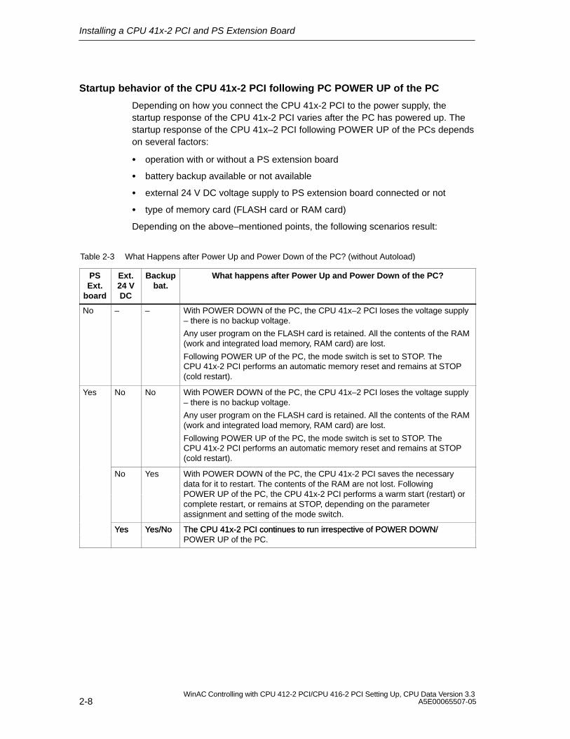
Table 2-3 What Happens after Power Up and Power Down of the PC? (without Autoload)
PSExt.
board
Ext.24 VDC
Backupbat.
What happens after Power Up and Power Down of the PC?
No – – With POWER DOWN of the PC, the CPU 41x–2 PCI loses the voltage supply– there is no backup voltage.
Any user program on the FLASH card is retained. All the contents of the RAM(work and integrated load memory, RAM card) are lost.
Following POWER UP of the PC, the mode switch is set to STOP. TheCPU 41x-2 PCI performs an automatic memory reset and remains at STOP(cold restart).
Yes No No With POWER DOWN of the PC, the CPU 41x–2 PCI loses the voltage supply– there is no backup voltage.
Any user program on the FLASH card is retained. All the contents of the RAM(work and integrated load memory, RAM card) are lost.
Following POWER UP of the PC, the mode switch is set to STOP. TheCPU 41x-2 PCI performs an automatic memory reset and remains at STOP(cold restart).
No Yes With POWER DOWN of the PC, the CPU 41x-2 PCI saves the necessarydata for it to restart. The contents of the RAM are not lost. Following POWER UP of the PC, the CPU 41x-2 PCI performs a warm start (restart) orcomplete restart, or remains at STOP, depending on the parameterassignment and setting of the mode switch.
Yes Yes/No The CPU 41x-2 PCI continues to run irrespective of POWER DOWN/Yes Yes/No The CPU 41x-2 PCI continues to run irrespective of POWER DOWN/POWER UP of the PC.
Installing a CPU 41x-2 PCI and PS Extension Board
2-9WinAC Controlling with CPU 412-2 PCI/CPU 416-2 PCI Setting Up, CPU Data Version 3.3A5E00065507-05
When are the warm restart (restart) and Autoload functions possible?
Warm restart (restart)
A warm restart (restart) following the PC being powered up is possible only withthe PS extension board and backup battery.
Autoload
If you are not using the PS extension board, you can load user data by means ofthe “Autoload” function (refer to Section 5.5).
With the “Autoload” function, the PC automatically fetches a STEP 7 user program(stored in a memory card file) following power down and power up and loads it ontothe CPU 41x-2 PCI. Following that, the CPU 41x-2 PCI automatically selects thestatus that it had stored beforehand and, depending on the status, the STEP 7user program is executed.
Table 2-4 When Are the Warm Restart (Restart) and Autoload Functions Possible?
PSextension
board
Ext. 24 V DCsupply
Backupbattery
Memory card Warm restart (restart)possible after complete
restart following power upof the PCs?
Autoloadfunction
possible?
No – – RAM card/none No Yes
FLASH Card No No
Yes No No RAM card/none No Yes
FLASH Card No No
No Yes RAM card/none Yes No
FLASH Card Yes No
Yes No RAM card/none Irrelevant* Yes
FLASH Card Irrelevant* No
Yes Yes RAM card/none Irrelevant* No
FLASH Card Irrelevant* No
* CPU 41x-2 PCI continues to be supplied from the external 24 V DC source.
Installing a CPU 41x-2 PCI and PS Extension Board
2-10WinAC Controlling with CPU 412-2 PCI/CPU 416-2 PCI Setting Up, CPU Data Version 3.3
A5E00065507-05
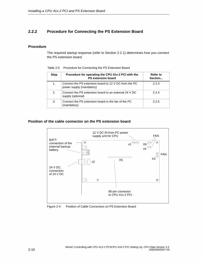
2.2.2 Procedure for Connecting the PS Extension Board
Procedure
The required startup response (refer to Section 2.2.1) determines how you connectthe PS extension board.
Table 2-5 Procedure for Connecting the PS Extension Board
Step Procedure for operating the CPU 41x-2 PCI with thePS extension board
Refer toSection...
1. Connect the PS extension board to 12 V DC from the PCpower supply (mandatory)
2.2.3
2. Connect the PS extension board to an external 24 V DCsupply (optional)
2.2.4
3. Connect the PS extension board to the fan of the PC(mandatory)
2.2.5
Position of the cable connector on the PS extension board
24 V DC: connectionof 24 V DC
BATT:connection of theexternal backupbattery
12 V DC IN from PC powersupply unit for CPU
x2
x1
X5
80-pin connectorto CPU 41x-2 PCI
FAN
X6
x4
X3
FAN
Figure 2-4 Position of Cable Connectors on PS Extension Board
Installing a CPU 41x-2 PCI and PS Extension Board
2-11WinAC Controlling with CPU 412-2 PCI/CPU 416-2 PCI Setting Up, CPU Data Version 3.3A5E00065507-05
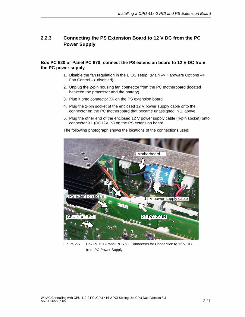
2.2.3 Connecting the PS Extension Board to 12 V DC from the PCPower Supply
Box PC 620 or Panel PC 670: connect the PS extension board to 12 V DC fromthe PC power supply
1. Disable the fan regulation in the BIOS setup (Main –> Hardware Options –>Fan Control –> disabled).
2. Unplug the 2-pin housing fan connector from the PC motherboard (locatedbetween the processor and the battery).
3. Plug it onto connector X6 on the PS extension board.
4. Plug the 2-pin socket of the enclosed 12 V power supply cable onto theconnector on the PC motherboard that became unassigned in 1. above.
5. Plug the other end of the enclosed 12 V power supply cable (4-pin socket) ontoconnector X1 (DC12V IN) on the PS extension board.
The following photograph shows the locations of the connections used:
Motherboard
PS extension board
CPU 41x-2 PCI
12 V power supply cable
X6
X1 DC12V IN
Figure 2-5 Box PC 620/Panel PC 760: Connectors for Connection to 12 V DC
from PC Power Supply
Installing a CPU 41x-2 PCI and PS Extension Board
2-12WinAC Controlling with CPU 412-2 PCI/CPU 416-2 PCI Setting Up, CPU Data Version 3.3
A5E00065507-05
Other PCs: connect the PS extension board to external 12 V DC source from PCpower supply
1. Plug one of the supply connectors from the PC onto connector X1 on thePS extension board.
If the cable from the supply connector is too short or if no supply connector isavailable any more on the PC, insert the Y-cable (included in the PS extensionboard package). By using the Y-cable, you do not lose any supply connector ofthe PC for other applications.
2.2.4 Connecting the PS Extension Board to an External 24 V DCSupply (Optional)
Requirements for connection to external 24 V DC
For the CPU 41x-2 PCI and the PS extension board, the whole supply with 24 V DC has to be generated as a safety extra-low voltage (SELV).
!Warning
Personal injury or material damage can result.
If you do not design the 24 V DC supply of the PS extension board correctly,components can be damaged and individuals may be injured.
The 24 V DC supply must satisfy the following requirements:
Only the extra–low voltage 60 V DC, properly isolated from the mains, can beused as the load current power supply. Proper isolation can be implemented inaccordance with the requirements, among others, of VDE 0100, Part 410 /HD 384-4-41 / IEC 364-4-41 (as functional extra-low voltage with proper isolation)or VDE 0805 / EN 60950 / IEC 950 (as safety extra-low voltage, SELV) orVDE 0106, Part 101.
Connecting the PS extension board to an external 24 V DC supply
1. Connecting to an external 24 V DC voltage supply (optional): In thePS extension board package there is a 3-core cable having a connector withpush/pull locking against inadvertent removal.
Plug the 3-pin connector onto connector X2 on the slot plate of thePS extension board.
2. Connect the cable for the 24 V DC supply to the voltage supply as shown inTable 2-6.
Installing a CPU 41x-2 PCI and PS Extension Board
2-13WinAC Controlling with CPU 412-2 PCI/CPU 416-2 PCI Setting Up, CPU Data Version 3.3A5E00065507-05
Table 2-6 Terminal Assignment of the External 24 V DC Supply
Contact Color
L+ Red
M Black
PE Brown
Cable for connection of 24 V DC to PS extension board
The cable contained in the package is 1.5 m long.
The following initial condition must be observed when this cable is used:
< 2 m: minimum diameter of stranded wire 0.5 mm
> 2 m: minimum diameter of stranded wire 0.75 mm (refer to UL 1950,Section 3.2.4, Table 11)
2.2.5 Connecting a Fan to the PS Extension Board
You must connect the fan on the PC to the PS extension board. When the PC failsor is turned off and the PS extension board is connected to an external 24 V DCsupply voltage, the CPU 41x-2 PCI continues to be cooled by the fan.
Authorized PC fans
Only UL, CSA certified fans are authorized within their technical specifications.
Connection options
The PS extension board has three connection options for the fan of the PC (X3, X4or X6) – depending on the type of connector. Terminals X3, X4 and X6 togetherprovide 300 mA at 12 V. Terminals X3, X4 and X6 can be operated in parallel, too.
1. Remove the connector that is connected to the fan from the motherboard orpower supply and connect the connector to X3, X4 or X6.
Installing a CPU 41x-2 PCI and PS Extension Board
2-14WinAC Controlling with CPU 412-2 PCI/CPU 416-2 PCI Setting Up, CPU Data Version 3.3
A5E00065507-05
2.3 Installing and Connecting the Backup Battery
Affixing the battery holder
There are several ways in which you can attach the backup holder in a batteryholder on the PC :
Install the battery holder instead of a free slot plate on the PC
Fix the battery holder to the PC housing
Box PC 620 and 820: Fix the battery holder to the PC
!Warning
When opening the PC, make absolutely certain you follow the relevant safetyinformation in the manual for the PC.
!Warning
For safety reasons, the lithium battery must be attached in an area protectedagainst mechanical impairment.
Battery holder on slot plate
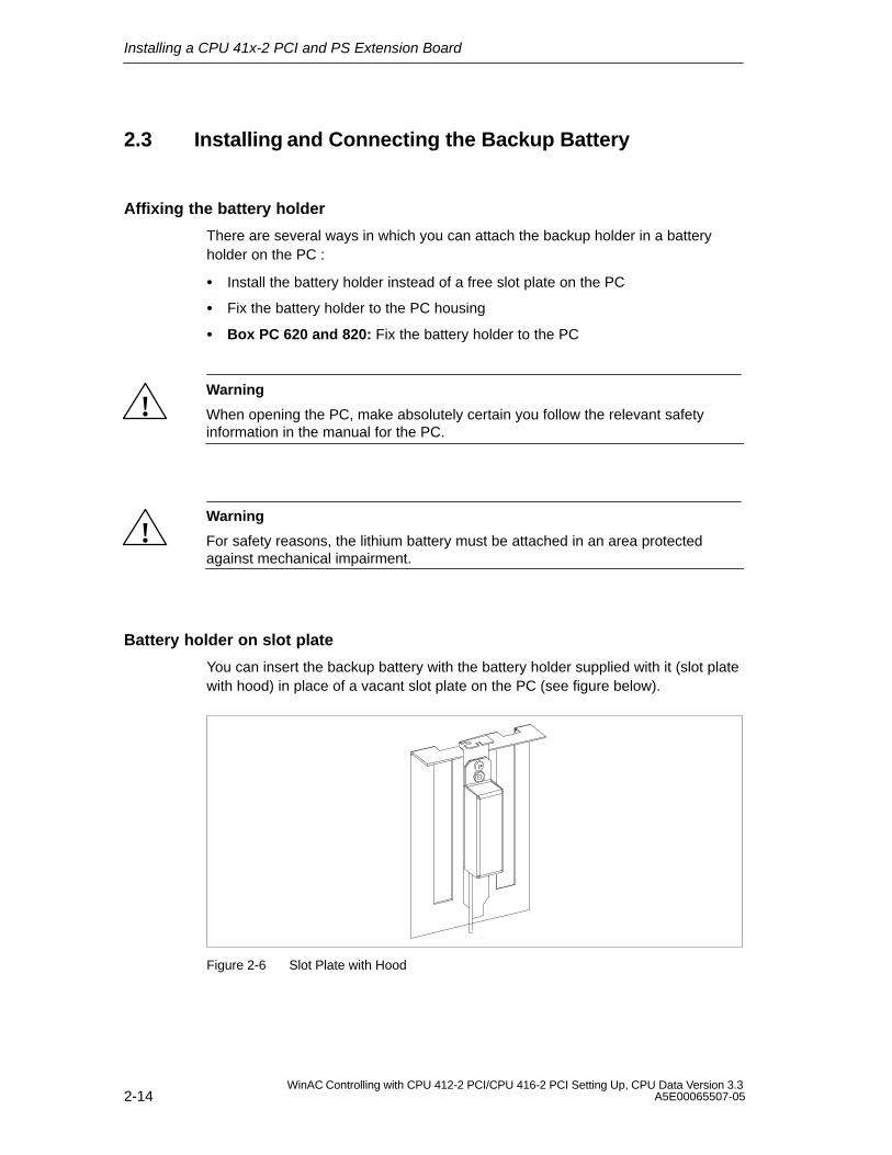
You can insert the backup battery with the battery holder supplied with it (slot platewith hood) in place of a vacant slot plate on the PC (see figure below).
1:1
Figure 2-6 Slot Plate with Hood
Installing a CPU 41x-2 PCI and PS Extension Board
2-15WinAC Controlling with CPU 412-2 PCI/CPU 416-2 PCI Setting Up, CPU Data Version 3.3A5E00065507-05
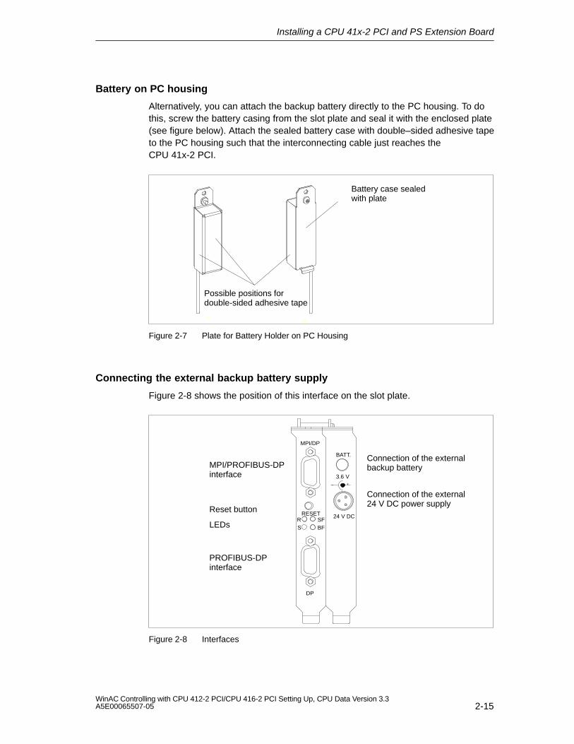
Battery on PC housing
Alternatively, you can attach the backup battery directly to the PC housing. To dothis, screw the battery casing from the slot plate and seal it with the enclosed plate(see figure below). Attach the sealed battery case with double–sided adhesive tapeto the PC housing such that the interconnecting cable just reaches the CPU 41x-2 PCI.
Possible positions fordouble-sided adhesive tape
Battery case sealedwith plate
1:1
1:1
Figure 2-7 Plate for Battery Holder on PC Housing
Connecting the external backup battery supply
Figure 2-8 shows the position of this interface on the slot plate.
Connection of the externalbackup battery
PROFIBUS-DPinterface
MPI/PROFIBUS-DPinterface
MPI/DP
RESETSFBFS
R
DP
Reset button
Connection of the external24 V DC power supply
LEDs
+–
BATT.
3.6 V
24 V DC
Figure 2-8 Interfaces
Installing a CPU 41x-2 PCI and PS Extension Board
2-16WinAC Controlling with CPU 412-2 PCI/CPU 416-2 PCI Setting Up, CPU Data Version 3.3
A5E00065507-05
A lithium battery (type AA, 3.6 V cell voltage) is used for the standby power supplyto the CPU 41x-2 PCI.
A battery pack with a suitable backup battery in a prewired battery holder issupplied in the WinAC Slot 41x package.
For the incoming supply, there is a 2-pin 4.95 mm socket on the slot plate of thePS extension board. This socket is available for an SO connector without slidingsleeve to DIN 45323 for connecting external power supplies for battery-powereddevices.
However, its assignment does not conform to DIN – in other words, the innercontact is the positive pole and the outer contact is the negative pole. As a result,there cannot be a short-circuit with the CPU slot plate when removing or insertingthe connector to the backup battery.
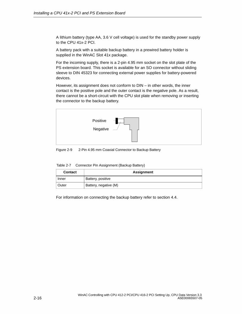
Positive
Negative
Figure 2-9 2-Pin 4.95 mm Coaxial Connector to Backup Battery
Table 2-7 Connector Pin Assignment (Backup Battery)
Contact Assignment
Inner Battery, positive
Outer Battery, negative (M)
For information on connecting the backup battery refer to section 4.4.
Installing a CPU 41x-2 PCI and PS Extension Board
2-17WinAC Controlling with CPU 412-2 PCI/CPU 416-2 PCI Setting Up, CPU Data Version 3.3A5E00065507-05
2.4 Checks before Initial Turn-On of the PC withCPU 41x-2 PCI
Introduction
After installing and wiring your CPU 41x-2 PCI, we recommend that you check thesteps you have performed so far before you turn on your PC for the first time.
Checks prior to initial power up
Table 2-8 provides instructions for checking your automation system in the form ofa check list.
Table 2-8 Check List for Checks before Turning on the PC for the First Time
Check the following items
Has the CPU 41x-2 PCI been properly inserted and screwed tight?
Has a memory card been inserted?
When using a PS extension board:
Has the 80-pin connector between the CPU 41x-2 PCI and the PS extension boardbeen properly inserted?
Has the PS extension board been screwed to the CPU 41x-2 PCI?
Has the PS extension board been connected to the PC power supply unit?
Is the PC fan connected to the PS extension board?
Has the connector for feeding in the external power supply been properly wired?
Has the backup battery been connected?
Has the switch for battery monitoring been properly set?
Have the slot plates been screwed to the PC?
Close the PC as described in your manual.

Installing a CPU 41x-2 PCI and PS Extension Board
2-18WinAC Controlling with CPU 412-2 PCI/CPU 416-2 PCI Setting Up, CPU Data Version 3.3
A5E00065507-05
3-1WinAC Controlling with CPU 412-2 PCI/CPU 416-2 PCI Setting Up, CPU Data Version 3.3A5E00065507-05
Installing WinAC Slot 41x
In this chapter
Section Contents Page
3.1 Installing the WinAC Slot 41x Software 3-1
3.2 Component Configurator: Configure PC Components within thePC
3-4
3.3 Uninstalling the WinAC Slot 41x Software 3-6
3.1 Installing the WinAC Slot 41x Software
The WinAC Slot 41x software features separate setup features for theCPU 412-2 PCI and the CPU 416-2 PCI, together with the other softwarecomponents (control panel, SIMATIC Computing, Tool Manager, and timesynchronization).
System requirements
For installing the components of WinAC Slot 41x, we recommend the followingrequirements for your computer:
A personal computer (PC) with the following:
– Pentium processor running at 300 MHz or faster
– Not less than 128 MB RAM
– Microsoft Windows 2000 Professional, SP 3 or later orMicrosoft Windows XP Professional, SP 1 or later.
A color monitor, keyboard, and mouse (or other pointing device) that aresupported by Microsoft Windows
A hard disk with at least 120 MB of spare storage space
At least 60 Mbyte free memory capacity on drive C for the Setup program(Setup files are deleted when the installation is complete)
1 PCI slot for 3/4-length cards at standard spacing and one adjacent vacant slotfor an optional PS extension board.
3
Installing WinAC Slot 41x
3-2WinAC Controlling with CPU 412-2 PCI/CPU 416-2 PCI Setting Up, CPU Data Version 3.3
A5E00065507-05
Requirements
Before you can install a software package, the following requirements must bemet:
Windows 2000 Professional or Windows XP Professional must be installed.
You have logged on with administrator privileges. If not, important entries in theWindows registry cannot be made effectively and the installation will remainincomplete.
If an earlier version of WinAC Basis or WinAC Pro has been installed,
you must uninstall any older versions before installing the new version. Refer tosection 3.3 for information.
Order of installation
When installing the different software packages, we recommend that you installthem in the following order:
1. Install the following components using the general setup
– control panel (minimum)
– time synchronization, if you want to synchronize the CPU 41x-2 PCI using aSIMATIC CP
– SIMATIC Computing, if you want to use ActiveX Controls or OPC
2. STEP 7, as necessary
3. WinCC or ProTool/Pro, as necessary
4. Network components, as necessary.
Installing WinAC Slot 41x
3-3WinAC Controlling with CPU 412-2 PCI/CPU 416-2 PCI Setting Up, CPU Data Version 3.3A5E00065507-05
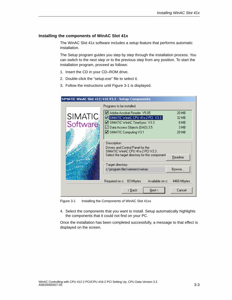
Installing the components of WinAC Slot 41x
The WinAC Slot 41x software includes a setup feature that performs automaticinstallation.
The Setup program guides you step by step through the installation process. Youcan switch to the next step or to the previous step from any position. To start theinstallation program, proceed as follows:
1. Insert the CD in your CD–ROM drive.
2. Double-click the “setup.exe” file to select it.
3. Follow the instructions until Figure 3-1 is displayed.
Figure 3-1 Installing the Components of WinAC Slot 41xx
4. Select the components that you want to install. Setup automatically highlightsthe components that it could not find on your PC.
Once the installation has been completed successfully, a message to that effect isdisplayed on the screen.
Installing WinAC Slot 41x
3-4WinAC Controlling with CPU 412-2 PCI/CPU 416-2 PCI Setting Up, CPU Data Version 3.3
A5E00065507-05
Troubleshooting any errors that occur during installation
The following errors will result in installation being aborted:
Inadequate memory: you require at least 120 MB of space on your hard disk.
Defective CD: if you establish that the CD is defective, please contact yourlocal Siemens agent.
3.2 Component Configurator: Configure PC Componentswithin the PC
Function of the component configurator
You notify the following settings to the PC with the help of the componentconfigurator:
Station name,
Type of CPU 41x-2 PCI and
Name of CPU 41x-2 PCI.
Note
The settings in the component configurator must match the subsequent configura-tion in “STEP 7/Configure Hardware”:
Station name
Type
Index (corresponds to the slot in “Configure Hardware”) and
Name.
Index
The CPU 41x-2 PCI is automatically operated on index 3. The index correspondsto a virtual slot on the PC.
Installing WinAC Slot 41x
3-5WinAC Controlling with CPU 412-2 PCI/CPU 416-2 PCI Setting Up, CPU Data Version 3.3A5E00065507-05
Name
Note
The name that you assign to the CPU 41x-2 PCI in the component configuratorthen corresponds to the name by which you call the control panel of the CPU fromthe taskbar. If, for example, you assign the name Slot_CPU to the CPU 41x-2 PCI,call the control panel at Start > Simatic > PC Based Control > Slot_CPU.
Information about the component configurator
You will find more information about diagnostics in the component configurator, forexample, in the appropriate online Help.
Procedure
To assign the name to the PC
1. Open the component configurator by clicking on the
button on the taskbar.
Installing WinAC Slot 41x
3-6WinAC Controlling with CPU 412-2 PCI/CPU 416-2 PCI Setting Up, CPU Data Version 3.3
A5E00065507-05
3.3 Uninstalling the WinAC Slot 41x Software
Observe the following points before you start to uninstall:
The corresponding software components must not be in use when the softwareis uninstalled.
Uninstalling the components of the WinAC Slot 41x software
Perform the following steps to remove the WinAC Slot 41x software from yourcomputer:
1. Double-click on the “Software” icon on the Control Panel.
2. Select one of the WinAC Slot 41x components you want to have uninstalledfrom the list of installed software. Click the ”Add/Remove” button to uninstall thesoftware.
3. If the “Remove Enable Files” dialog box appears, click the “No” button if you areunsure how to respond.
Note
Study the Readme files of the software components concerned.
4-1WinAC Controlling with CPU 412-2 PCI/CPU 416-2 PCI Setting Up, CPU Data Version 3.3A5E00065507-05
Commissioning
In this chapter
Section Contents Page
4.1 Points to Note when Integrating the Software 4-1
4.2 Recommended Procedure for Commissioning 4-2
4.3 Resetting the CPU with the Mode Switch 4-4
4.4 Connecting a Backup Battery (Option) 4-5
4.5 Reset Button: Resetting the Module 4-8
4.1 Points to Note when Integrating the Software
Module state
The ”Module State” window displays order number 6ES7 612-2QH00-0AB4 for theCPU 412-2 PCI and order number 6ES7 616-2QL00-0AB4 for the CPU 416-2 PCI.Note that you can only purchase the CPU 41x-2 PCI as a spare part using theseorder numbers.
Configuring STEP 7 hardware
You configure a CPU 41x-2 PCI in SIMATIC Manager by choosing Insert >Station > SIMATIC PC Station from the menu.
In Step 7/Configure Hardware select for the
CPU 412-2 PCI: SIMATIC PC Station > Controller > CPU 412-2 PCI >6ES7 612-2QH00-0AB4 > V3.1 or
CPU 416-2 PCI: SIMATIC PC Station > Controller > CPU 416-2 PCI >6ES7 616-2QL00-0AB4 > V3.1.
A configured CP is not displayed following an upload of a configuration from aCPU 41x-2 PCI.
4
Commissioning
4-2WinAC Controlling with CPU 412-2 PCI/CPU 416-2 PCI Setting Up, CPU Data Version 3.3
A5E00065507-05
Reserved address area for a technological application
!Caution
In the CPU 412-2 PCI, PEW 4096 to 8190 and PAW 4096 to 8190 – in theCPU 416-2 PCI the PEW 16384 to 20478 and PAW 16384 to 20478 – arereserved for a technological application.
If you access the above address area in your STEP 7 user program, anI/O access error is not generated, irrespective of whether or not a technologicalfunction is being operated in this area.
4.2 Recommended Procedure for Commissioning
Introduction
Due to the fact that there are so many expansion options, a PC-based automationsystem with the CPU 41x-2 PCI can be very large and complex. We recommendthat you commission your device step by step by
1. Commissioning the PC and the CPU 41x-2 PCI, followed by
2. Commissioning the connected I/O
After you have installed your CPU 41x-2 PCI on the PC and performed the checksdescribed in section 2.4, you can turn on your PC.
Commissioning a PC with a CPU 41x-2 PCI
To commission a PC having a CPU 41x-2 PCI, we recommend that you performthe following steps:
1. Make sure once more that you have properly installed and parameterized theCPU 41x-2 PCI (refer to the check list in section 2.4).
2. Disconnect any DP line that is connected.
3. Turn on the PC.
4. Open the control panel:
Start > Simatic > PC Based Control > CPU 412-2 PCI or Start > Simatic > PC Based Control > CPU 416-2 PCI
Note
It is assumed in the following that you have saved the CPU 41x-2 PCI in thecomponent configurator as “CPU 412-2 PCI” or “CPU 416-2 PCI”.
Commissioning
4-3WinAC Controlling with CPU 412-2 PCI/CPU 416-2 PCI Setting Up, CPU Data Version 3.3A5E00065507-05
5. The following LEDs light on the control panel:
– the green LED ON
– the yellow LED STOP
Check the backup battery and the position of switch S1 to inhibit batterymonitoring if the red LED BATF is also on.
Up-to-date information about the control panel is stored in a readme file. Youcan open these readme files in the following directory:
Start > Simatic > Product Notes > English
Should error messages be output to the screen when installing the controlpanel, read the Readme file before taking any further action.
6. Press the RUN button on the control panel.
You are then prompted to enter your password. The default password for thecontrol panel is ”” (no password or RETURN).
Once you have entered your password, the LEDs STOP and RUN light. TheCPU is now in RUN mode.
7. Press the STOP button on the control panel.
The RUN LED goes out, and the STOP LED lights. The CPU is now in STOPmode.
8. If you are using a PS extension board and want to check out the internal supplyby means of the PC power supply unit, you can detach the external voltagesupply and check whether the CPU 41x-2 PCI continues to operate.
9. Connect the CPU 41x-2 PCI step by step to the other components.
Commissioning
4-4WinAC Controlling with CPU 412-2 PCI/CPU 416-2 PCI Setting Up, CPU Data Version 3.3
A5E00065507-05
4.3 Resetting the CPU with the Mode Switch
Introduction
When you reset a CPU, you return the CPU memory to a defined initial state.Furthermore, the CPU initializes its hardware parameters and some of the systemprogram parameters. If you have inserted a FLASH card with a user program inthe CPU, the CPU transfers the user program and the system parameters storedon the FLASH card to the CPU work memory subsequent to a reset operation.
When do you reset the CPU memory?
When the CPU prompts you to reset, you must perform resetting from thecontrol panel. You will recognize this prompt from the fact that the STOP LEDflashes slowly at 0.5 Hz.
We recommend a complete reset before you transfer a new, complete userprogram to the CPU.
How do you reset?
There are two ways of resetting the CPU memory:
From the control panel (MRES)
Via STEP 7
Resetting process in the CPU
The following procedure is performed in the CPU during a reset operation:
The CPU deletes the whole user program from the work memory and loadmemory (integrated RAM and possibly RAM card).
The CPU deletes all counters, memory markers and timers (apart from the timeof day).
The CPU tests its own hardware.
The CPU initializes its hardware and system program parameters – in otherwords, internal CPU (default) settings. Some assigned default settings areretained.
If there is no FLASH card plugged in, a reset CPU will have a reset state of ”0”.You can read out the state in STEP 7.
If you have inserted a FLASH card, the CPU copies the user program and thesystem parameters stored on the FLASH card to the work memory after a resethas been performed.
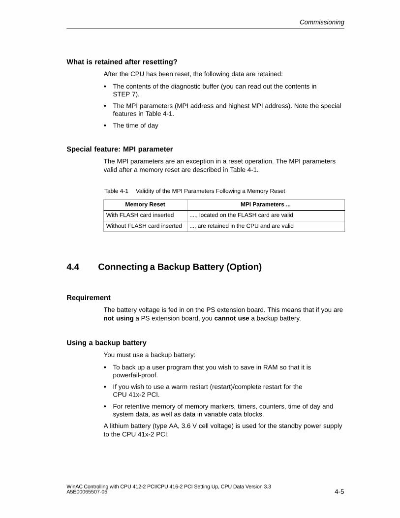
Commissioning
4-5WinAC Controlling with CPU 412-2 PCI/CPU 416-2 PCI Setting Up, CPU Data Version 3.3A5E00065507-05
What is retained after resetting?
After the CPU has been reset, the following data are retained:
The contents of the diagnostic buffer (you can read out the contents inSTEP 7).
The MPI parameters (MPI address and highest MPI address). Note the specialfeatures in Table 4-1.
The time of day
Special feature: MPI parameter
The MPI parameters are an exception in a reset operation. The MPI parametersvalid after a memory reset are described in Table 4-1.
Table 4-1 Validity of the MPI Parameters Following a Memory Reset
Memory Reset MPI Parameters ...
With FLASH card inserted ...., located on the FLASH card are valid
Without FLASH card inserted ..., are retained in the CPU and are valid
4.4 Connecting a Backup Battery (Option)
Requirement
The battery voltage is fed in on the PS extension board. This means that if you arenot using a PS extension board, you cannot use a backup battery.
Using a backup battery
You must use a backup battery:
To back up a user program that you wish to save in RAM so that it ispowerfail-proof.
If you wish to use a warm restart (restart)/complete restart for theCPU 41x-2 PCI.
For retentive memory of memory markers, timers, counters, time of day andsystem data, as well as data in variable data blocks.
A lithium battery (type AA, 3.6 V cell voltage) is used for the standby power supplyto the CPU 41x-2 PCI.
Commissioning
4-6WinAC Controlling with CPU 412-2 PCI/CPU 416-2 PCI Setting Up, CPU Data Version 3.3
A5E00065507-05
!Warning
Risk of injury and material damage, risk of hazardous substances escaping.
If handled wrongly, a lithium battery can explode; improper disposal of old lithiumbatteries may result in hazardous substances escaping. It is therefore imperativethat you comply with the following information:
Do not throw new or spent batteries into the fire and do not solder on the cellbody (maximum temperature of 100 °C); do not recharge as there is a risk ofexplosion.
Do not open the battery and replace it only with an identical type. Obtain yourreplacement only from Siemens. This will ensure that you are in possession ofa short-circuit-proof type.
To the extent possible, return old batteries to the battery manufacturer orforward them to a recycler, or dispose of them as hazardous waste.
Removing the passivation layer
When lithium batteries (lithium/thionyl chloride) are used as backup batteries, apassivation layer may form after very long periods of storage and cast doubt on theimmediate ability of the battery to operate. One of the consequences is an errormessage after the PS extension board is turned off.
The CPU 41x-2 PCI is capable of removing the passivation layer on the lithiumbattery by means of defined battery loading. This process may last severalminutes. When the passivation layer has been destroyed and the lithium batteryhas reached its rated voltage, the error message on the control panel has to beacknowledged by choosing the option CPU > FMR from the menu.
Since the time the lithium battery has spent in storage is generally not known, werecommend that you perform the following steps:
1. Connect the backup battery to the “BATT.” socket on the slot plate of thePS extension board.
2. If a battery error message is displayed on the control panel (”BATF” LED),acknowledge it by choosing the option CPU > FMR from the menu.
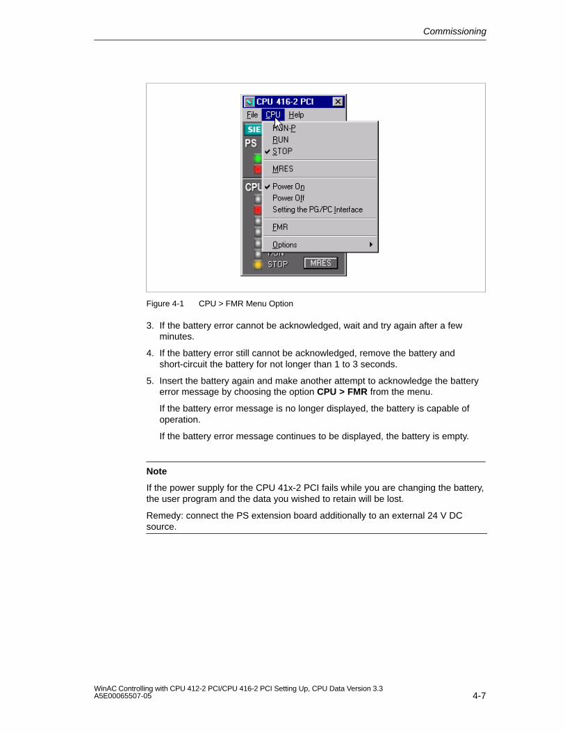
Commissioning
4-7WinAC Controlling with CPU 412-2 PCI/CPU 416-2 PCI Setting Up, CPU Data Version 3.3A5E00065507-05
Figure 4-1 CPU > FMR Menu Option
3. If the battery error cannot be acknowledged, wait and try again after a fewminutes.
4. If the battery error still cannot be acknowledged, remove the battery andshort-circuit the battery for not longer than 1 to 3 seconds.
5. Insert the battery again and make another attempt to acknowledge the batteryerror message by choosing the option CPU > FMR from the menu.
If the battery error message is no longer displayed, the battery is capable ofoperation.
If the battery error message continues to be displayed, the battery is empty.
Note
If the power supply for the CPU 41x-2 PCI fails while you are changing the battery,the user program and the data you wished to retain will be lost.
Remedy: connect the PS extension board additionally to an external 24 V DCsource.
Commissioning
4-8WinAC Controlling with CPU 412-2 PCI/CPU 416-2 PCI Setting Up, CPU Data Version 3.3
A5E00065507-05
4.5 Reset Button: Resetting the Module
The reset pushbutton (operate for not less than 1 second) on the slot plate of theCPU 41x-2 PCI can be used to reset the CPU 41x-2 PCI without the control panel.For safety reasons, the CPU 41x-2 PCI then goes automatically to STOP.
Following that, you can change to RUN only by means of the mode switch on thecontrol panel.
5-1WinAC Controlling with CPU 412-2 PCI/CPU 416-2 PCI Setting Up, CPU Data Version 3.3A5E00065507-05
CPU 412-2 PCI and CPU 416-2 PCI ControlPanel
In this chapter
Section Contents Page
5.1 Overview 5-2
5.2 Controls and Display Elements of CPU 41x-2 PCI 5-3
5.3 Status and Error Indications 5-4
5.4 Operating Mode Controls 5-8
5.5 Loading and Saving the STEP 7 User Program 5-11
5.6 CPU 41x-2 PCI Controls on the Menu Bar 5-16
5
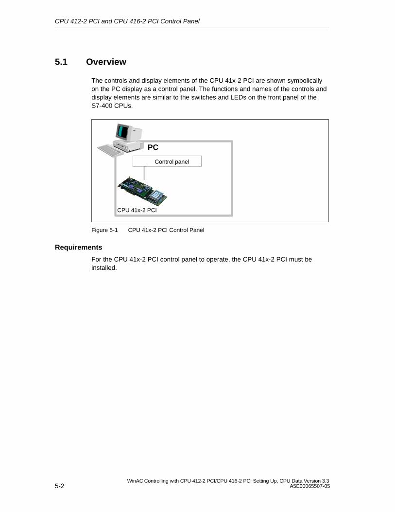
CPU 412-2 PCI and CPU 416-2 PCI Control Panel
5-2WinAC Controlling with CPU 412-2 PCI/CPU 416-2 PCI Setting Up, CPU Data Version 3.3
A5E00065507-05
5.1 Overview
The controls and display elements of the CPU 41x-2 PCI are shown symbolicallyon the PC display as a control panel. The functions and names of the controls anddisplay elements are similar to the switches and LEDs on the front panel of theS7-400 CPUs.
Control panel
PC
CPU 41x-2 PCI
Figure 5-1 CPU 41x-2 PCI Control Panel
Requirements
For the CPU 41x-2 PCI control panel to operate, the CPU 41x-2 PCI must beinstalled.
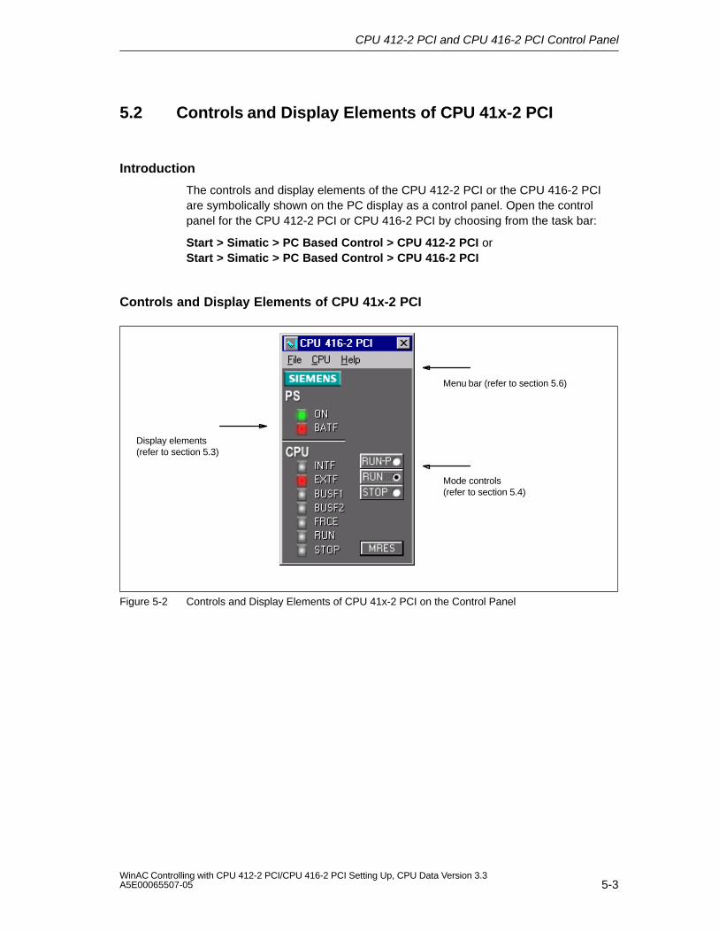
CPU 412-2 PCI and CPU 416-2 PCI Control Panel
5-3WinAC Controlling with CPU 412-2 PCI/CPU 416-2 PCI Setting Up, CPU Data Version 3.3A5E00065507-05
5.2 Controls and Display Elements of CPU 41x-2 PCI
Introduction
The controls and display elements of the CPU 412-2 PCI or the CPU 416-2 PCIare symbolically shown on the PC display as a control panel. Open the controlpanel for the CPU 412-2 PCI or CPU 416-2 PCI by choosing from the task bar:
Start > Simatic > PC Based Control > CPU 412-2 PCI or Start > Simatic > PC Based Control > CPU 416-2 PCI
Controls and Display Elements of CPU 41x-2 PCI
Menu bar (refer to section 5.6)
Mode controls (refer to section 5.4)
Display elements (refer to section 5.3)
Figure 5-2 Controls and Display Elements of CPU 41x-2 PCI on the Control Panel
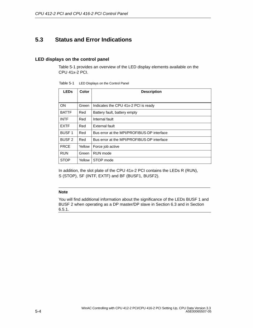
CPU 412-2 PCI and CPU 416-2 PCI Control Panel
5-4WinAC Controlling with CPU 412-2 PCI/CPU 416-2 PCI Setting Up, CPU Data Version 3.3
A5E00065507-05
5.3 Status and Error Indications
LED displays on the control panel
Table 5-1 provides an overview of the LED display elements available on theCPU 41x-2 PCI.
Table 5-1 LED Displays on the Control Panel
LEDs Color Description
ON Green Indicates the CPU 41x-2 PCI is ready
BATTF Red Battery fault, battery empty
INTF Red Internal fault
EXTF Red External fault
BUSF 1 Red Bus error at the MPI/PROFIBUS-DP interface
BUSF 2 Red Bus error at the MPI/PROFIBUS-DP interface
FRCE Yellow Force job active
RUN Green RUN mode
STOP Yellow STOP mode
In addition, the slot plate of the CPU 41x-2 PCI contains the LEDs R (RUN), S (STOP), SF (INTF, EXTF) and BF (BUSF1, BUSF2).
Note
You will find additional information about the significance of the LEDs BUSF 1 andBUSF 2 when operating as a DP master/DP slave in Section 6.3 and in Section6.5.1.
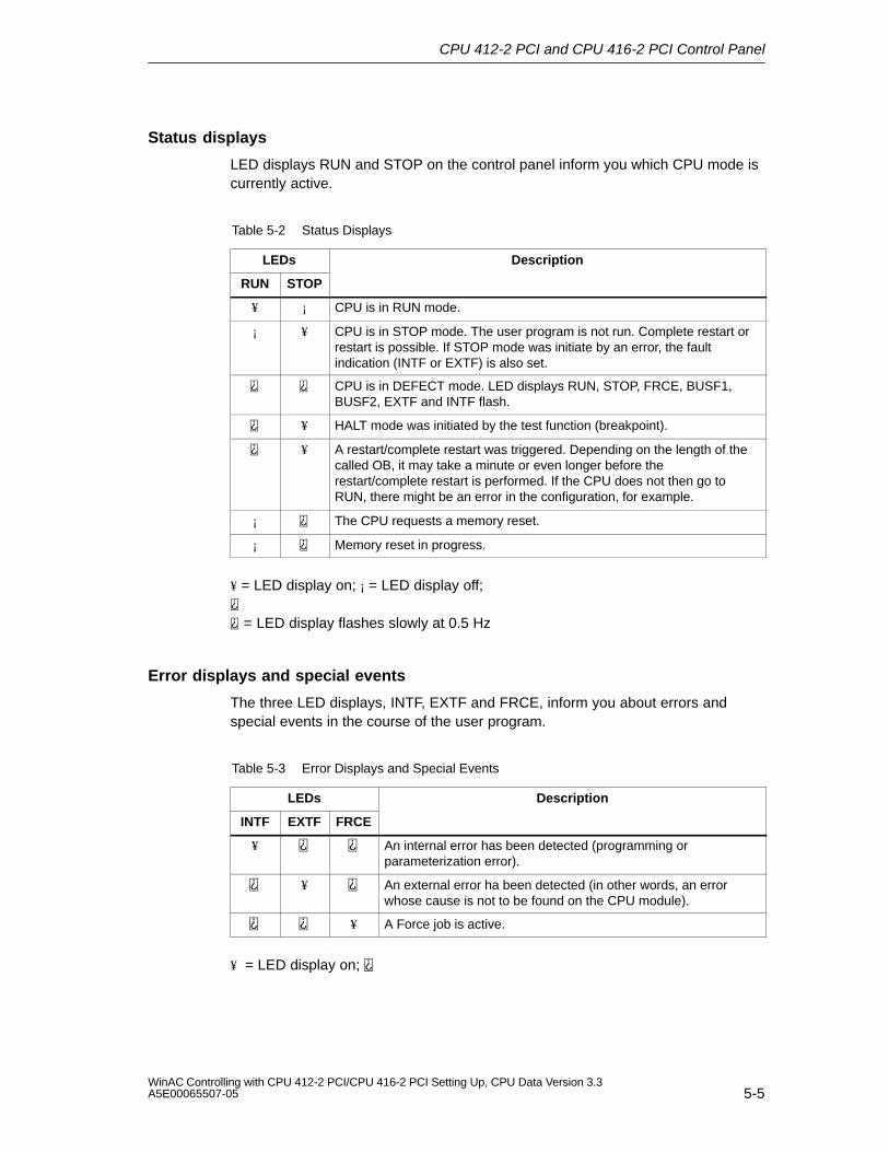
CPU 412-2 PCI and CPU 416-2 PCI Control Panel
5-5WinAC Controlling with CPU 412-2 PCI/CPU 416-2 PCI Setting Up, CPU Data Version 3.3A5E00065507-05
Status displays
LED displays RUN and STOP on the control panel inform you which CPU mode iscurrently active.
Table 5-2 Status Displays
LEDs Description
RUN STOP
¥ ¡ CPU is in RUN mode.
¡ ¥ CPU is in STOP mode. The user program is not run. Complete restart orrestart is possible. If STOP mode was initiate by an error, the faultindication (INTF or EXTF) is also set.
CPU is in DEFECT mode. LED displays RUN, STOP, FRCE, BUSF1,BUSF2, EXTF and INTF flash.
¥ HALT mode was initiated by the test function (breakpoint).
¥ A restart/complete restart was triggered. Depending on the length of thecalled OB, it may take a minute or even longer before therestart/complete restart is performed. If the CPU does not then go toRUN, there might be an error in the configuration, for example.
¡ The CPU requests a memory reset.
¡ Memory reset in progress.
¥ = LED display on; ¡ = LED display off;
= LED display flashes slowly at 0.5 Hz
Error displays and special events
The three LED displays, INTF, EXTF and FRCE, inform you about errors andspecial events in the course of the user program.
Table 5-3 Error Displays and Special Events
LEDs Description
INTF EXTF FRCE
¥ An internal error has been detected (programming orparameterization error).
¥ An external error ha been detected (in other words, an errorwhose cause is not to be found on the CPU module).
¥ A Force job is active.
¥ = LED display on;
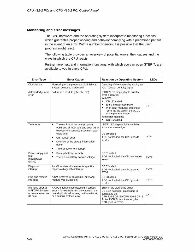
CPU 412-2 PCI and CPU 416-2 PCI Control Panel
5-6WinAC Controlling with CPU 412-2 PCI/CPU 416-2 PCI Setting Up, CPU Data Version 3.3
A5E00065507-05
Monitoring and error messages
The CPU hardware and the operating system incorporate monitoring functionswhich guarantee proper working and behavior complying with a predefined patternin the event of an error. With a number of errors, it is possible that the userprogram might react.
The following table provides an overview of potential errors, their causes and theways in which the CPU reacts.
Furthermore, test and information functions, with which you can open STEP 7, areavailable to you in every CPU.
Error Type Error Cause Reaction by Operating System LEDs
Clock failure Monitoring of the processor clock failureSystem comes to a standstill.
Disabling of the outputs by issuing an”OD” (Output Disable) signal
–
Acknowledgementerror
Failure of a module (SM, FM, CP) ”EXTF” LED display lights until theerror is cleared.With SMs: OB 122 called Entry in diagnostic buffer With input modules: entering of
”zero” as the date in the ACCUor the process image
With other modules: OB 122 called
EXTF
Timer error The run time of the user program(OB1 and all interrupts and error OBs)exceeds the specified maximum scancycle time.
OB request error
Overflow of the startup informationbuffer
Time-of-day error interrupt
”INTF” LED display lights until theerror is acknowledged.
OB 80 calledIf OB not loaded: the CPU goes toSTOP.
INTF
Power supply unitfault(not a powerfailure)
Backup battery is empty
There is no battery backup voltage
OB 81 calledIf OB not loaded: the CPU continuesto run.
EXTF
Diagnosticinterrupt
An I/O module with interrupt capabilityreports a diagnostic interrupt.
OB 82 calledIf OB not loaded: the CPU goes toSTOP.
EXTF
Plug and removeinterrupt
A SM removed or plugged in, or wrongmodule type plugged in.
OB 83 calledIf OB not loaded: the CPU goes toSTOP.
EXTF
Interface error atMPI/DP/AS-internal communications(C bus)
A CPU interface has detected a seriouserror – for example, a short–circuit on thebus, duplicate addressing on the network,or a serious protocol error.
Entry in the diagnostic bufferOB 84 is no longer processed, incontrast to theCPU 416-2 DP ISA/CPU 416-2 DP ISA Lite. If OB 84 is not loaded, theCPU goes to STOP.
EXTF
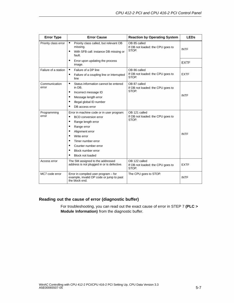
CPU 412-2 PCI and CPU 416-2 PCI Control Panel
5-7WinAC Controlling with CPU 412-2 PCI/CPU 416-2 PCI Setting Up, CPU Data Version 3.3A5E00065507-05
Error Type LEDsReaction by Operating SystemError Cause
Priority class error Priority class called, but relevant OBmissing.
With SFB call: instance DB missing orfault.
OB 85 calledIf OB not loaded: the CPU goes toSTOP. INTF
Error upon updating the processimage. EXTF
Failure of a station Failure of a DP line
Failure of a coupling line or interruptedline
OB 86 calledIf OB not loaded: the CPU goes toSTOP.
EXTF
Communicationerror
Status information cannot be enteredin DB.
Incorrect message ID
Message length error
Illegal global ID number
DB access error
OB 87 calledIf OB not loaded: the CPU goes toSTOP.
INTF
Programmingerror
Error in machine code or in user program:
BCD conversion error
Range length error
Range error
Alignment error
Write error
Timer number error
Counter number error
Block number error
Block not loaded
OB 121 calledIf OB not loaded: the CPU goes toSTOP.
INTF
Access error The SM assigned to the addressedaddress is not plugged in or is defective.
OB 122 calledIf OB not loaded: the CPU goes toSTOP.
EXTF
MC7 code error Error in compiled user program – forexample, invalid OP code or jump to pastthe block end.
The CPU goes to STOP.INTF
Reading out the cause of error (diagnostic buffer)
For troubleshooting, you can read out the exact cause of error in STEP 7 (PLC >Module Information) from the diagnostic buffer.
CPU 412-2 PCI and CPU 416-2 PCI Control Panel
5-8WinAC Controlling with CPU 412-2 PCI/CPU 416-2 PCI Setting Up, CPU Data Version 3.3
A5E00065507-05
5.4 Operating Mode Controls
In this chapter
Section Contents Page
5.4.1 Selecting the Startup Type 5-9
5.4.2 Protection Levels 5-10
You can use the operating mode controls to change the CPU to RUN/RUN-P modeor to STOP mode, or to reset the CPU. STEP 7 features other options for changingthe operating mode.
Table 5-4 explains the operation of the operating mode controls. If an error occurs, orif any obstacles are encountered during startup, the CPU will go to or remain at STOP,irrespective of operation.
Table 5-4 Operation of the Controls
Operation Description
RUN-P If no obstacle is encountered during startup and if no error has occurred and the CPUsucceeded in going to RUN, the CPU processes the user program or idles. Accessesto the I/O are possible.
Programs can: Be read from the CPU using a programming device (CPU ⇒ PG), Transferred to the CPU (PG ⇒ CPU).
RUN If no obstacle is encountered during startup and if no error has occurred and the CPUsucceeded in going to RUN, the CPU processes the user program or idles. Accessesto the I/O are possible.
Programs in the CPU can be read out with the programming device (CPU ⇒ PG).
The program in the CPU cannot be modified at switch setting RUN. (Refer to STEP 7) The protection level can be bypassed by a password set inSTEP 7/Configure Hardware – in other words, when this password is known, theprogram can be modified at switch setting RUN.
STOP The CPU does not execute the user program. The signal modules are inhibited.
Programs can: Be read from the CPU using a programming device (CPU ⇒ PG), Transferred to the CPU (PG ⇒ CPU).
MRES The CPU goes to STOP mode. In this instance, the following tasks are performed:
The CPU deletes the entire user program from its load and work memories. If a flash card is inserted, the program stored on the flash card will be initiated
following a memory reset. The CPU resets the memory areas (I, O, M, T, and C).After the memory has been reset, the diagnostic buffer remains unchanged, as does theMPI address.
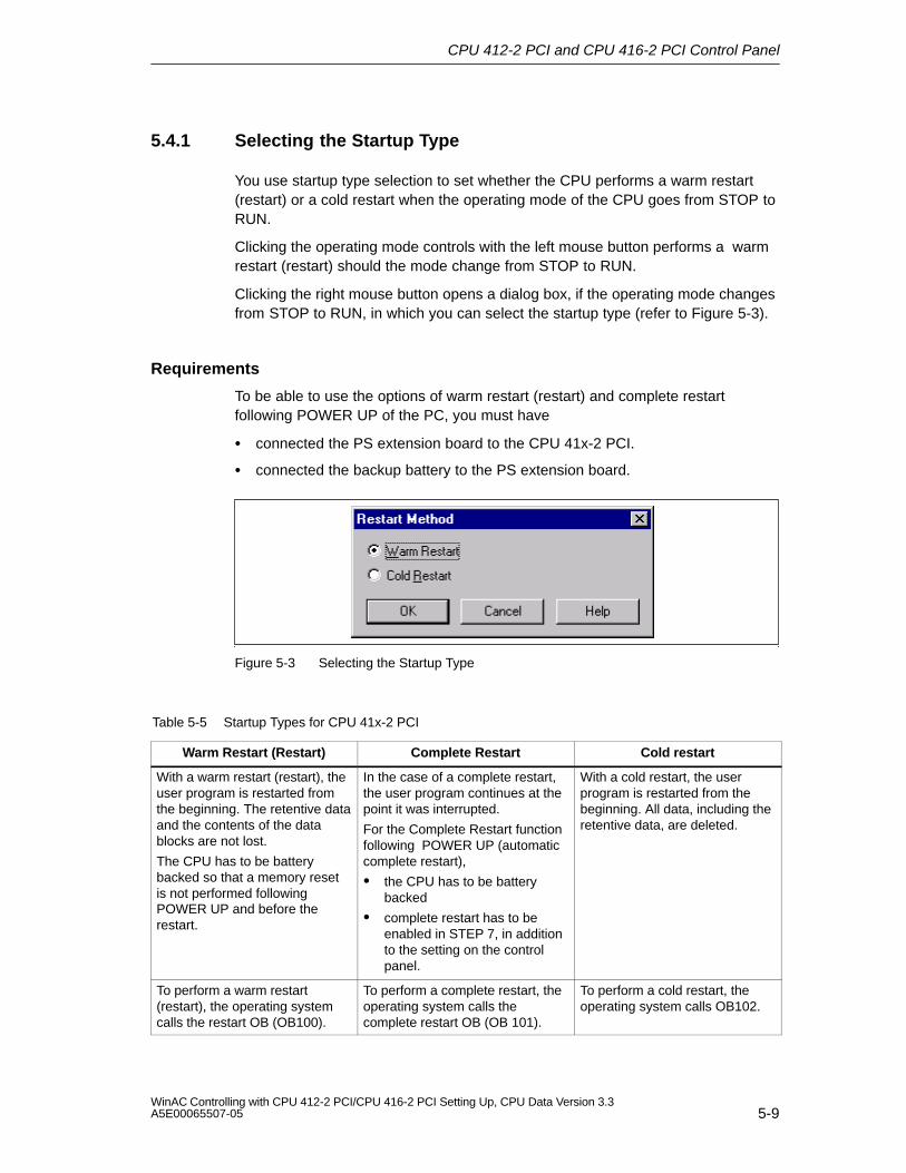
CPU 412-2 PCI and CPU 416-2 PCI Control Panel
5-9WinAC Controlling with CPU 412-2 PCI/CPU 416-2 PCI Setting Up, CPU Data Version 3.3A5E00065507-05
5.4.1 Selecting the Startup Type
You use startup type selection to set whether the CPU performs a warm restart(restart) or a cold restart when the operating mode of the CPU goes from STOP toRUN.
Clicking the operating mode controls with the left mouse button performs a warmrestart (restart) should the mode change from STOP to RUN.
Clicking the right mouse button opens a dialog box, if the operating mode changesfrom STOP to RUN, in which you can select the startup type (refer to Figure 5-3).
Requirements
To be able to use the options of warm restart (restart) and complete restartfollowing POWER UP of the PC, you must have
connected the PS extension board to the CPU 41x-2 PCI.
connected the backup battery to the PS extension board.
Figure 5-3 Selecting the Startup Type
Table 5-5 Startup Types for CPU 41x-2 PCI
Warm Restart (Restart) Complete Restart Cold restart
With a warm restart (restart), theuser program is restarted fromthe beginning. The retentive dataand the contents of the datablocks are not lost.
The CPU has to be batterybacked so that a memory resetis not performed followingPOWER UP and before therestart.
In the case of a complete restart,the user program continues at thepoint it was interrupted.
For the Complete Restart functionfollowing POWER UP (automaticcomplete restart),
the CPU has to be batterybacked
complete restart has to beenabled in STEP 7, in additionto the setting on the controlpanel.
With a cold restart, the userprogram is restarted from thebeginning. All data, including theretentive data, are deleted.
To perform a warm restart(restart), the operating systemcalls the restart OB (OB100).
To perform a complete restart, theoperating system calls thecomplete restart OB (OB 101).
To perform a cold restart, theoperating system calls OB102.
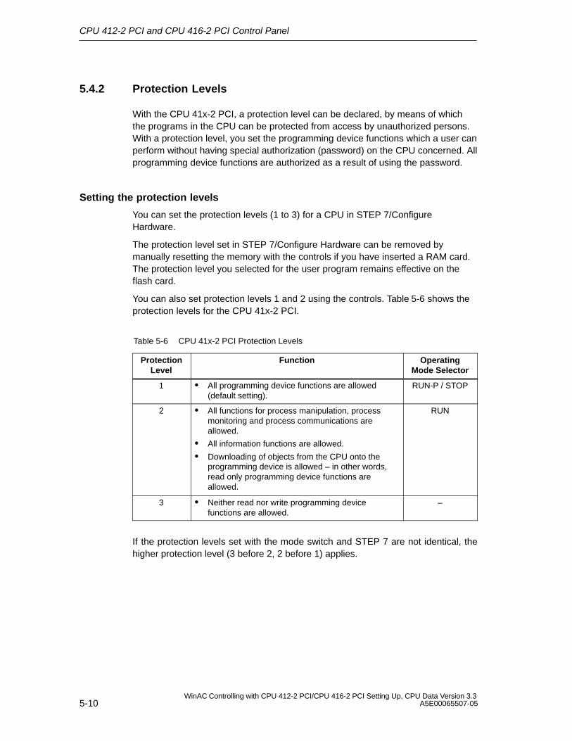
CPU 412-2 PCI and CPU 416-2 PCI Control Panel
5-10WinAC Controlling with CPU 412-2 PCI/CPU 416-2 PCI Setting Up, CPU Data Version 3.3
A5E00065507-05
5.4.2 Protection Levels
With the CPU 41x-2 PCI, a protection level can be declared, by means of whichthe programs in the CPU can be protected from access by unauthorized persons.With a protection level, you set the programming device functions which a user canperform without having special authorization (password) on the CPU concerned. Allprogramming device functions are authorized as a result of using the password.
Setting the protection levels
You can set the protection levels (1 to 3) for a CPU in STEP 7/ConfigureHardware.
The protection level set in STEP 7/Configure Hardware can be removed bymanually resetting the memory with the controls if you have inserted a RAM card.The protection level you selected for the user program remains effective on theflash card.
You can also set protection levels 1 and 2 using the controls. Table 5-6 shows theprotection levels for the CPU 41x-2 PCI.
Table 5-6 CPU 41x-2 PCI Protection Levels
ProtectionLevel
Function OperatingMode Selector
1 All programming device functions are allowed(default setting).
RUN-P / STOP
2 All functions for process manipulation, processmonitoring and process communications areallowed.
All information functions are allowed.
Downloading of objects from the CPU onto theprogramming device is allowed – in other words,read only programming device functions areallowed.
RUN
3 Neither read nor write programming devicefunctions are allowed.
–
If the protection levels set with the mode switch and STEP 7 are not identical, thehigher protection level (3 before 2, 2 before 1) applies.
CPU 412-2 PCI and CPU 416-2 PCI Control Panel
5-11WinAC Controlling with CPU 412-2 PCI/CPU 416-2 PCI Setting Up, CPU Data Version 3.3A5E00065507-05
5.5 Loading and Saving the STEP 7 User Program
In this chapter
Section Contents Page
5.5.1 A Few Explanations before Proceeding 5-11
5.5.2 Saving and Loading the STEP 7 User Program 5-12
5.5.1 A Few Explanations before Proceeding
Load and work memories
When you load the STEP 7 user program into the CPU 41x-2 PCI, the logic anddata blocks are loaded into the load and work memories of the CPU 41x-2 PCI.
To ensure rapid processing of the STEP 7 user program, only those parts of theblocks that are important for program scanning are loaded into the work memory.Block sections that are not necessary for running the program (for example, blockheaders) remain in the load memory.
The following figure illustrates loading of the program into the CPU memory:
Work memoryLogic blocks
Saved on hard disk
Symbols
Data blocks
Wholelogic blocks
Wholedata blocks
Parts of logic anddata blocksrequired for
running
Load memory
Comments
STEP 7
CPU 41x-2 PCI
Figure 5-4 Loading the STEP 7 User Program into the Memory of CPU 41x-2 PCI
CPU 412-2 PCI and CPU 416-2 PCI Control Panel
5-12WinAC Controlling with CPU 412-2 PCI/CPU 416-2 PCI Setting Up, CPU Data Version 3.3
A5E00065507-05
Structure of the load memory
You can expand the load memory by means of a memory card. Depending onwhether you select a RAM card or a FLASH card for expanding the load memory,the response during loading, reloading and memory reset may differ. You will findfurther information on this topic in Chapter 10.
Definition
A memory card file is equivalent to the contents of the memory card. Thememory card file contains the STEP 7 user program and the hardwareconfiguration (SDBs). If you create the memory card file with the help of STEP 7, the DBs will contain theinitial values.
If you create the memory card file using the control panel by choosingFile –> Archive by CPU, the DBs will contain the current values.
5.5.2 Saving and Loading the STEP 7 User Program
The memory card can only be withdrawn and plugged in when the PC is open. Youhave the option, however, of reading STEP 7 user programs from theCPU 41x-2 PCI or storing them on the CPU 41x-2 PCI without your having toremove and plug in the memory card:
With the File > Archive function, you can load the STEP 7 user program andthe hardware configuration from the load memory of the CPU 41x-2 PCI ontothe PC (memory card file).
With the File > Restore function, you can load a STEP 7 user program and thehardware configuration from the PC (memory card file) into the load memory ofthe CPU 41x-2 PCI.
By means of the CPU > Options > Autoload function, the PC fetches amemory card file you preselected after a POWER UP and loads this file into theload memory of the CPU 41x-2 PCI. The STEP 7 user program then runs onthe CPU 41x-2 PCI.
CPU 412-2 PCI and CPU 416-2 PCI Control Panel
5-13WinAC Controlling with CPU 412-2 PCI/CPU 416-2 PCI Setting Up, CPU Data Version 3.3A5E00065507-05
Archiving
With the File > Archive function, you can save on the PC the STEP 7 userprogram and the hardware configuration residing on the CPU 41x-2 PCI. Thecontrol panel reads out the load memory of the CPU 41x-2 PCI and stores this filewith the extension “*.wld” on the hard disk.
This file (memory card file) contains the STEP 7 user program and the currenthardware configuration (DBs).
This function is also supported in SIMATIC Manager with File > Memory CardFile.
PC withSTEP 7
Memory cardfiles
Control Panel
Load memory
Work memory
CPU 41x-2 PCI
Figure 5-5 Archiving
CPU 412-2 PCI and CPU 416-2 PCI Control Panel
5-14WinAC Controlling with CPU 412-2 PCI/CPU 416-2 PCI Setting Up, CPU Data Version 3.3
A5E00065507-05
Restore
With the File > Restore function, you can load a STEP 7 user program and thehardware configuration from the PC into the load memory of the CPU 41x-2 PCI.
First, select a memory card file having an extension “*.wld” and load it into the loadmemory of the CPU 41x-2 PCI.
PC withSTEP 7
Memory cardfiles Load memory
CPU 41x-2 PCI
Work memory
Control Panel
Figure 5-6 Restoring
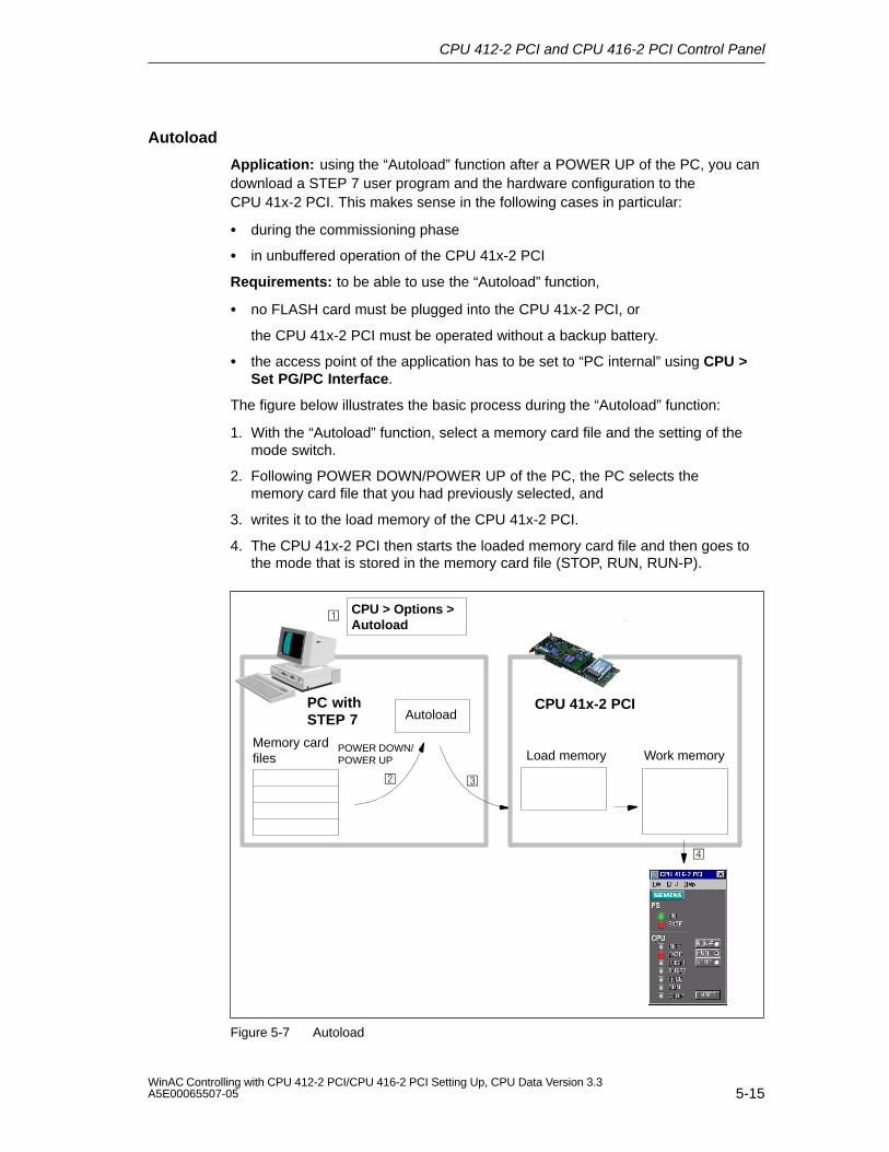
CPU 412-2 PCI and CPU 416-2 PCI Control Panel
5-15WinAC Controlling with CPU 412-2 PCI/CPU 416-2 PCI Setting Up, CPU Data Version 3.3A5E00065507-05
Autoload
Application: using the “Autoload” function after a POWER UP of the PC, you candownload a STEP 7 user program and the hardware configuration to theCPU 41x-2 PCI. This makes sense in the following cases in particular:
during the commissioning phase
in unbuffered operation of the CPU 41x-2 PCI
Requirements: to be able to use the “Autoload” function,
no FLASH card must be plugged into the CPU 41x-2 PCI, or
the CPU 41x-2 PCI must be operated without a backup battery.
the access point of the application has to be set to “PC internal” using CPU >Set PG/PC Interface.
The figure below illustrates the basic process during the “Autoload” function:
1. With the “Autoload” function, select a memory card file and the setting of themode switch.
2. Following POWER DOWN/POWER UP of the PC, the PC selects thememory card file that you had previously selected, and
3. writes it to the load memory of the CPU 41x-2 PCI.
4. The CPU 41x-2 PCI then starts the loaded memory card file and then goes tothe mode that is stored in the memory card file (STOP, RUN, RUN-P).
PC withSTEP 7
Memory cardfiles Load memory
CPU 41x-2 PCI
Work memory
CPU > Options >Autoload
Autoload
POWER DOWN/POWER UP
Figure 5-7 Autoload
CPU 412-2 PCI and CPU 416-2 PCI Control Panel
5-16WinAC Controlling with CPU 412-2 PCI/CPU 416-2 PCI Setting Up, CPU Data Version 3.3
A5E00065507-05
5.6 CPU 41x-2 PCI Controls on the Menu Bar
In this chapter
The menu bar consists of three menus:
File menu
CPU menu
Help menu
Section Contents Page
5.6.1 ”File” Menu 5-17
5.6.2 ”CPU” Menu 5-18
5.6.3 ”Customize” Submenu 5-19
5.6.4 ”Safety” Submenu 5-21
5.6.5 “Connect CPU” submenu 5-23
5.6.6 ”Help” Menu 5-23
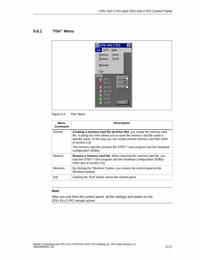
CPU 412-2 PCI and CPU 416-2 PCI Control Panel
5-17WinAC Controlling with CPU 412-2 PCI/CPU 416-2 PCI Setting Up, CPU Data Version 3.3A5E00065507-05
5.6.1 ”File” Menu
Figure 5-8 ”File” Menu
MenuCommand
Description
Archive Creating a memory card file (archive file): you create the memory cardfile. A dialog box then allows you to save the memory card file under aspecific name. In this way you can create several memory card files (referto section 5.5).
The memory card file contains the STEP 7 user program and the hardwareconfiguration (SDBs).
Restore Restore a memory card file: When restoring the memory card file, youload the STEP 7 user program and the hardware configuration (SDBs)(refer also to section 5.5).
Minimize By clicking the ”Minimize” button, you reduce the control panel to theWindows taskbar.
Exit Clicking the ”Exit” button closes the control panel.
Note
After you exit from the control panel, all the settings and states on theCPU 41x-2 PCI remain active.
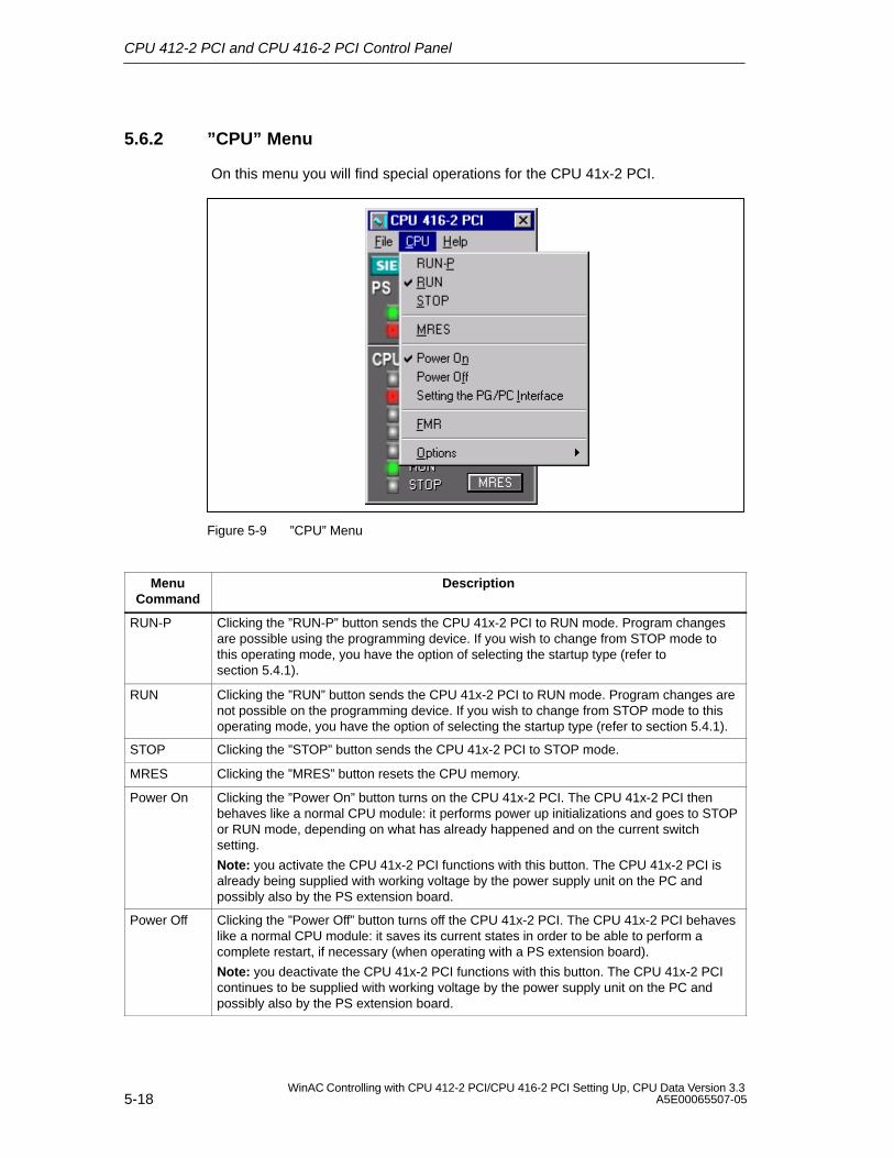
CPU 412-2 PCI and CPU 416-2 PCI Control Panel
5-18WinAC Controlling with CPU 412-2 PCI/CPU 416-2 PCI Setting Up, CPU Data Version 3.3
A5E00065507-05
5.6.2 ”CPU” Menu
On this menu you will find special operations for the CPU 41x-2 PCI.
Figure 5-9 ”CPU” Menu
MenuCommand
Description
RUN-P Clicking the ”RUN-P” button sends the CPU 41x-2 PCI to RUN mode. Program changesare possible using the programming device. If you wish to change from STOP mode tothis operating mode, you have the option of selecting the startup type (refer tosection 5.4.1).
RUN Clicking the ”RUN” button sends the CPU 41x-2 PCI to RUN mode. Program changes arenot possible on the programming device. If you wish to change from STOP mode to thisoperating mode, you have the option of selecting the startup type (refer to section 5.4.1).
STOP Clicking the ”STOP” button sends the CPU 41x-2 PCI to STOP mode.
MRES Clicking the ”MRES” button resets the CPU memory.
Power On Clicking the ”Power On” button turns on the CPU 41x-2 PCI. The CPU 41x-2 PCI thenbehaves like a normal CPU module: it performs power up initializations and goes to STOPor RUN mode, depending on what has already happened and on the current switchsetting.
Note: you activate the CPU 41x-2 PCI functions with this button. The CPU 41x-2 PCI isalready being supplied with working voltage by the power supply unit on the PC andpossibly also by the PS extension board.
Power Off Clicking the ”Power Off” button turns off the CPU 41x-2 PCI. The CPU 41x-2 PCI behaveslike a normal CPU module: it saves its current states in order to be able to perform acomplete restart, if necessary (when operating with a PS extension board).
Note: you deactivate the CPU 41x-2 PCI functions with this button. The CPU 41x-2 PCIcontinues to be supplied with working voltage by the power supply unit on the PC andpossibly also by the PS extension board.
CPU 412-2 PCI and CPU 416-2 PCI Control Panel
5-19WinAC Controlling with CPU 412-2 PCI/CPU 416-2 PCI Setting Up, CPU Data Version 3.3A5E00065507-05
MenuCommand
Description
Setting thePG/PCInterface
When you operate this button, you call the “Set PG/PC Interface” program, which you canuse, say, to set the access of STEP 7 (PC internal when accessing within the PC) or to setthe network access for time synchronization.
FMR Clicking the ”FMR” button acknowledges the battery fault (refer also to section 4.4).
Options Selecting the ”Options” button opens another submenu with the menu options
Customize
Security
Connect CPU
5.6.3 ”Customize” Submenu
Clicking the ”Customize” button opens the Customize dialog box with three tabs:General, Language and Autoload.
GeneralOn this tab you can specify whether the control panel should always be displayedon top.
Figure 5-10 ”General” Tab
CPU 412-2 PCI and CPU 416-2 PCI Control Panel
5-20WinAC Controlling with CPU 412-2 PCI/CPU 416-2 PCI Setting Up, CPU Data Version 3.3
A5E00065507-05
Language
On this tab you select the language in which you would like to work. The languageis always changed collectively for the router, time synchronization, SIMATICComputing and Tool Manager applications. The new language does not take effectuntil the application has been restarted.
Figure 5-11 ”Language” Tab
CPU 412-2 PCI and CPU 416-2 PCI Control Panel
5-21WinAC Controlling with CPU 412-2 PCI/CPU 416-2 PCI Setting Up, CPU Data Version 3.3A5E00065507-05
Autoload
WinAC Slot 41x features an autoload function, which defines how WinAC Slot 41xreacts to POWER DOWN/POWER UP of the PC (refer to section 5.5). You can
load the STEP 7 user program automatically and
select the operating mode of the CPU 41x-2 PCI after loading the STEP 7 userprogram (STOP, RUN, RUN-P).
For the Autoload function, the access point of the application must be set“S7 Online ––> PC Internal” using CPU > Set PG/PC Interface.
Figure 5-12 ”Autoload” Tab
5.6.4 ”Safety” Submenu
You must always enter your password in the ”Access Rights” dialog box to openthe ”Access Protection” dialog box. Enter your password here. If a password hasnot yet been allocated, you can click ”OK” immediately.
Figure 5-13 ”Access Rights” Dialog Box
If the password has been entered correctly, the ”Access Protection” dialog box
CPU 412-2 PCI and CPU 416-2 PCI Control Panel
5-22WinAC Controlling with CPU 412-2 PCI/CPU 416-2 PCI Setting Up, CPU Data Version 3.3
A5E00065507-05
opens. In this dialog box, you have the option of authorizing different safety levelsfor operation of the CPU 41x-2 PCI Controller.
Password
Every manual change made on the CPU control panel (for example, change ofoperating mode) can be made only after the password has been entered.
Confirmation
Every manual change on the control panel (for example, change of operatingmode) has to be confirmed by acknowledging a message.
Without
Neither confirmation nor a password is necessary for changing the operating modeof the CPU.
Figure 5-14 ”Access Verification” Dialog Box
At ”Interval for Password Check”, you can set the period that has to elapse beforea password entry request is made not more than 23 hours and 59 minutes. Oncethe password has been entered, the system waits until the set period has elapsedbefore prompting for the password again.
You can change the current password by clicking ”Change Password”.
Figure 5-15 ”Change Password” Dialog Box
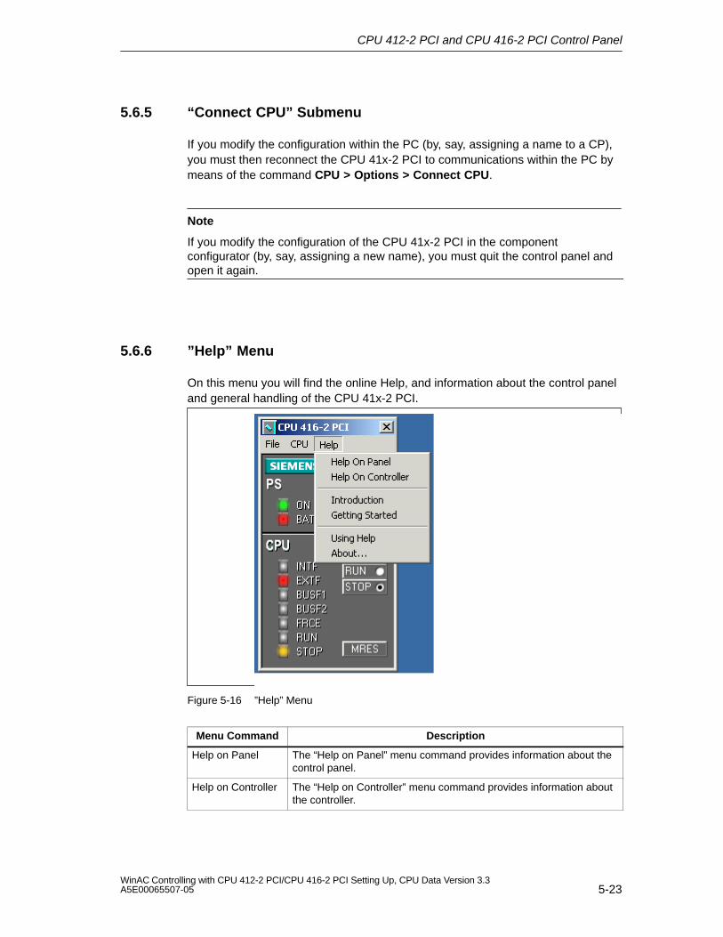
CPU 412-2 PCI and CPU 416-2 PCI Control Panel
5-23WinAC Controlling with CPU 412-2 PCI/CPU 416-2 PCI Setting Up, CPU Data Version 3.3A5E00065507-05
5.6.5 “Connect CPU” Submenu
If you modify the configuration within the PC (by, say, assigning a name to a CP),you must then reconnect the CPU 41x-2 PCI to communications within the PC bymeans of the command CPU > Options > Connect CPU.
Note
If you modify the configuration of the CPU 41x-2 PCI in the componentconfigurator (by, say, assigning a new name), you must quit the control panel andopen it again.
5.6.6 ”Help” Menu
On this menu you will find the online Help, and information about the control paneland general handling of the CPU 41x-2 PCI.
Figure 5-16 ”Help” Menu
Menu Command Description
Help on Panel The “Help on Panel” menu command provides information about thecontrol panel.
Help on Controller The “Help on Controller” menu command provides information aboutthe controller.
CPU 412-2 PCI and CPU 416-2 PCI Control Panel
5-24WinAC Controlling with CPU 412-2 PCI/CPU 416-2 PCI Setting Up, CPU Data Version 3.3
A5E00065507-05
Menu Command Description
Introduction Clicking the ”Introduction” button provides you with a conciseoverview of the use, important features and functional scope of theCPU 41x-2 PCI.
Getting Started Clicking the ”Getting Started” button shows you what you have to doin order to achieve initial success.
Using Help Clicking the “Using Help” button provides you with help on usingHelp.
About... Clicking the ”About...” button provides you with information about thecurrent version of the CPU 41x-2 PCI.
6-1WinAC Controlling with CPU 412-2 PCI/CPU 416-2 PCI Setting Up, CPU Data Version 3.3A5E00065507-05
CPU 41x-2 PCI as DP Master/DP Slave andDirect Data Exchange
Introduction
This chapter introduces to you the characteristics and technical specifications forCPUs 41x-2 PCI, which you will require when you use the CPU as a DP master oras a DP slave or for a direct exchange of data.
Declaration: since the DP master/DP slave response is the same for all CPUs, theCPUs will be referred to as CPU 41x-2 PCI in the following.
In this chapter
Section Contents Page
6.1 DP Address Area of CPUs 41x-2 PCI 6-2
6.2 CPU 41x-2 PCI as DP Master 6-3
6.3 Diagnostics of CPU 41x-2 PCI as DP Master 6-6
6.4 CPU 41x-2 PCI as DP Slave 6-11
6.5 Diagnostics of CPU 41x-2 PCI as DP Slave 6-16
6.6 Direct Data Exchange 6-31
6.7 Diagnostics During Direct Data Exchange 6-32
Further reading
Descriptions and information about configuration, configuring a PROFIBUS subnetand diagnostics the PROFIBUS subnet will be found in the STEP 7 online help.
6
CPU 41x-2 PCI as DP Master/DP Slave and Direct Data Exchange
6-2WinAC Controlling with CPU 412-2 PCI/CPU 416-2 PCI Setting Up, CPU Data Version 3.3
A5E00065507-05
6.1 DP Address Area of CPUs 41x-2 PCI
Address areas of CPUs 41x-2 PCI
Table 6-1 CPUs 41x-2 PCI (MPI/DP Interface as PROFIBUS-DP)
Address Area CPU 412-2 PCI CPU 416-2 PCI
MPI as PROFIBUS-DP, inputs andoutputs in each case (byte)
2048 2048
DP interface as PROFIBUS-DP, inputsand outputs in each case (byte)
4096 8192
Of which in the process image inputs and outputs in each caseadjustable up to x bytes
4096 16384
DP diagnostics addresses each require in the address area 1 byte for theDP master and each DP slave for the inputs. At these addresses, the DP standarddiagnostics for each node can be called, for example, (LADDR parameter ofSFC 13). You set the DP diagnostics addresses when you are configuring. If youdo not want to set DP diagnostics addresses, STEP 7 assigns the addresses fromthe highest byte address downwards as DP diagnostics addresses.
CPU 41x-2 PCI as DP Master/DP Slave and Direct Data Exchange
6-3WinAC Controlling with CPU 412-2 PCI/CPU 416-2 PCI Setting Up, CPU Data Version 3.3A5E00065507-05
6.2 CPU 41x-2 PCI as DP Master
Introduction
In this chapter we describe the characteristics and technical specifications of theCPU when you are operating it as a DP master.
You will find the characteristics and technical specifications of CPUs 41x-2 PCI inSection 8.2 and 8.3.
Requirements
Do you want the MPI/DP interface to be a DP interface? If so, you must configurethe interface as the DP interface.
You have to configure the CPU as the DP master before starting to commission.This means that you have to perform the following in STEP 7
Configure the CPU as the DP master
Assign a PROFIBUS address
Assign a master diagnostics address
Link the DP slaves to the DP master system.
Is one DP slave a CPU 41x-2 PCI?
If so, you will find this DP slave as a ”preconfigured station” in thePROFIBUS-DP catalog. You assign a slave diagnostics address to theDP slave CPU. You must connect the DP master to the DP slave CPU anddefine the address areas for data exchange to the DP slave CPU.
Status/Force, programming over PROFIBUS
As an alternative to the MPI, you can program the CPU through thePROFIBUS-DP interface, or you can execute the PG functions Status and Force.
Note
The use of programming or Status and Force through the PROFIBUS-DPinterface increases the DP scan cycle time.
Equidistance
In STEP 7 V 5.x or higher, you can parameterize bus scan cycles of identicallength (equidistant) for PROFIBUS subnets. You will find a detailed description ofequidistance in the STEP 7 online help.
CPU 41x-2 PCI as DP Master/DP Slave and Direct Data Exchange
6-4WinAC Controlling with CPU 412-2 PCI/CPU 416-2 PCI Setting Up, CPU Data Version 3.3
A5E00065507-05
Powering up the DP master system
You set power-up monitoring of the DP master with the following parameters:
Downloading of the parameters to modules
Completed message by module
In other words, the DP slaves have to power up within the set period and have tobe parameterized by the CPU (as the DP master).
PROFIBUS address of the DP master
All PROFIBUS addresses are allowed.
From EN 50170 to DPV1
The EN 50170 standard for distributed I/O has been further developed. The resultsof this development are contained in IEC 61158 / IEC 61784-1:2002 Ed1 CP 3/1. Inthe SIMATIC documentation this is designated as DPV1. The new version containsa few enhancements and simplifications.
Some SIEMENS automatization components already feature DPV1 functionality.You will have to make a few modifications to your system in order to use the newfunctions. A full description of the conversion from EN 50170 to DPV1 is availableas an FAQ entitled “Converting to DPV1”, FAQ contribution ID 7027576 at ourCustomer Support Internet site.
Components that support the Profibus DPV1 functionality
DPV1 Master
CPU 412-2 PCI/CPU 416-2 PCI firmware version 3.0 or later
DPV1 Slaves
DP slaves, which can be found in the STEP 7 hardware -Katalog under theirfamily names, are indicated in the information text as DPV1 slaves.
DP slaves, which are integrated in STEP 7 through GSD files beginning withGSD revision 3.
STEP 7
STEP 7 V5.1, SP 2 or later
CPU 41x-2 PCI as DP Master/DP Slave and Direct Data Exchange
6-5WinAC Controlling with CPU 412-2 PCI/CPU 416-2 PCI Setting Up, CPU Data Version 3.3A5E00065507-05
What operating modes are available for DPV1 components?
S7 compatible mode
In this mode the components are compatible to EN 50170. However, you do nothave full use of the DPV1 functions.
DPV1 mode
In this mode you have use of the DPV1 functions. You can continue to use asususal the automization components in the station that do not support DPV1.
Compatibility between DPV1 and EN 50170?
You can continue to use all of the existing slaves after converting to DPV1.However, they will not support the enhanced functions of DPV1.
You can even use the DPV1 slaves without converting to DPV1. They will thenreact like conventional slaves. SIEMENS DPV1 slaves can be operated in the S7compatible mode. For DPV1 slaves from other manufacturers you need a GSD fileconforming to EN 50170 earlier than revision 3.
Converting to DPV1
When you convert to DPV1, you must convert the entire station to DPV1. You canset this in STEP 7 in the hardware configuration (DP mode).
Determining the bus topology in a DP master system using SFC 103 ”DP_TOPOL”
The diagnostics repeater is available to improve you ability to detect faults duringongoing operation, for example, to identify a specific faulty module or the exactlocation of a break in the DP cable. This module is a slave that determines thetopology of a DP segment and can register faults that may occur within it.
SFC 103 ”DP_TOPOL” is used to trigger determination of the DP master system’sbus topology using the diagnostics repeater. SFC 103 is described in thecorresponding online help and in the “System and Standard Functions” manual.The diagnostics repeater is described in the manual , “Diagnostics Repeater forPROFIBUS-DP”, Order Number 6ES7972-0AB00-8AA0.
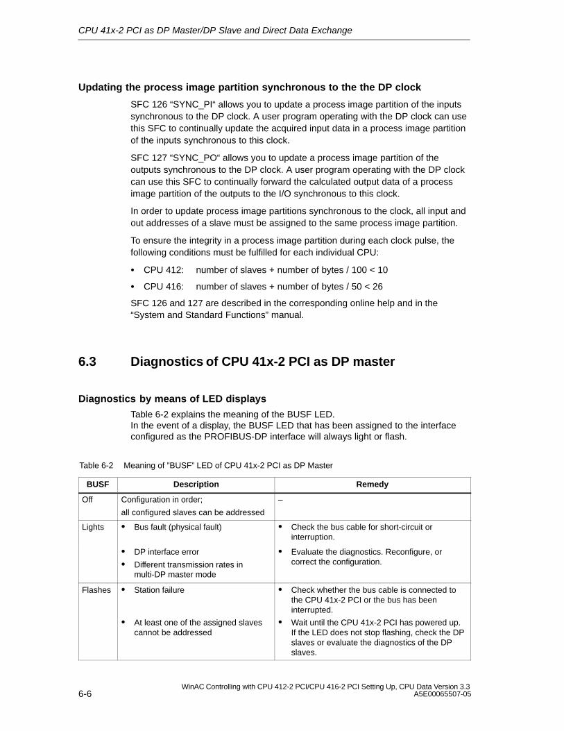
CPU 41x-2 PCI as DP Master/DP Slave and Direct Data Exchange
6-6WinAC Controlling with CPU 412-2 PCI/CPU 416-2 PCI Setting Up, CPU Data Version 3.3
A5E00065507-05
Updating the process image partition synchronous to the the DP clock
SFC 126 “SYNC_PI“ allows you to update a process image partition of the inputssynchronous to the DP clock. A user program operating with the DP clock can usethis SFC to continually update the acquired input data in a process image partitionof the inputs synchronous to this clock.
SFC 127 “SYNC_PO“ allows you to update a process image partition of theoutputs synchronous to the DP clock. A user program operating with the DP clockcan use this SFC to continually forward the calculated output data of a processimage partition of the outputs to the I/O synchronous to this clock.
In order to update process image partitions synchronous to the clock, all input andout addresses of a slave must be assigned to the same process image partition.
To ensure the integrity in a process image partition during each clock pulse, thefollowing conditions must be fulfilled for each individual CPU:
CPU 412: number of slaves + number of bytes / 100 < 10
CPU 416: number of slaves + number of bytes / 50 < 26
SFC 126 and 127 are described in the corresponding online help and in the“System and Standard Functions” manual.
6.3 Diagnostics of CPU 41x-2 PCI as DP master
Diagnostics by means of LED displays
Table 6-2 explains the meaning of the BUSF LED.In the event of a display, the BUSF LED that has been assigned to the interfaceconfigured as the PROFIBUS-DP interface will always light or flash.
Table 6-2 Meaning of ”BUSF” LED of CPU 41x-2 PCI as DP Master
BUSF Description Remedy
Off Configuration in order;
all configured slaves can be addressed
–
Lights Bus fault (physical fault) Check the bus cable for short-circuit orinterruption.
DP interface error
Different transmission rates inmulti-DP master mode
Evaluate the diagnostics. Reconfigure, orcorrect the configuration.
Flashes Station failure
At least one of the assigned slavescannot be addressed
Check whether the bus cable is connected tothe CPU 41x-2 PCI or the bus has beeninterrupted.
Wait until the CPU 41x-2 PCI has powered up.If the LED does not stop flashing, check the DPslaves or evaluate the diagnostics of the DPslaves.
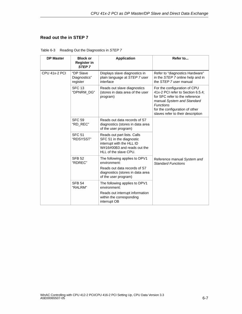
CPU 41x-2 PCI as DP Master/DP Slave and Direct Data Exchange
6-7WinAC Controlling with CPU 412-2 PCI/CPU 416-2 PCI Setting Up, CPU Data Version 3.3A5E00065507-05
Read out the in STEP 7
Table 6-3 Reading Out the Diagnostics in STEP 7
DP Master Block orRegister in
STEP 7
Application Refer to...
CPU 41x-2 PCI “DP SlaveDiagnostics”register
Displays slave diagnostics inplain language at STEP 7 userinterface
Refer to “diagnostics Hardware”in the STEP 7 online help and inthe STEP 7 user manual
SFC 13“DPNRM_DG”
Reads out slave diagnostics(stores in data area of the userprogram)
For the configuration of CPU41x-2 PCI refer to Section 6.5.4;for SFC refer to the referencemanual System and StandardFunctionsfor the configuration of otherslaves refer to their description
SFC 59“RD_REC”
Reads out data records of S7diagnostics (stores in data areaof the user program)
SFC 51“RDSYSST”
Reads out part lists. CallsSFC 51 in the diagnosticinterrupt with the HLL IDW#16#00B3 and reads out theHLL of the slave CPU.
SFB 52“RDREC”
The following applies to DPV1environment:
Reads out data records of S7diagnostics (stores in data areaof the user program)
Reference manual System andStandard Functions
SFB 54“RALRM”
The following applies to DPV1environment:
Reads out interrupt informationwithin the correspondinginterrupt OB
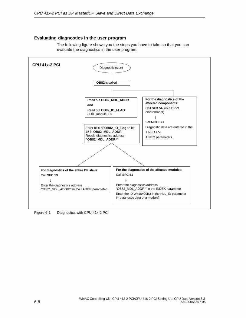
CPU 41x-2 PCI as DP Master/DP Slave and Direct Data Exchange
6-8WinAC Controlling with CPU 412-2 PCI/CPU 416-2 PCI Setting Up, CPU Data Version 3.3
A5E00065507-05
Evaluating diagnostics in the user program
The following figure shows you the steps you have to take so that you canevaluate the diagnostics in the user program.
Diagnostic event
Read out OB82_MDL_ADDR
and
Read out OB82_IO_FLAG (= I/O module ID)
For diagnostics of the entire DP slave:
Call SFC 13
Enter the diagnostics address“OB82_MDL_ADDR*” in the LADDR parameter
Enter bit 0 of OB82_IO_Flag as bit15 in OB82_MDL_ADDR Result: diagnostics address”OB82_MDL_ADDR*”
For the diagnostics of the affected modules:
Call SFC 51
Enter the diagnostics address“OB82_MDL_ADDR*” in the INDEX parameter
Enter the ID W#16#00B3 in the HLL_ID parameter(= diagnostic data of a module)
CPU 41x-2 PCI
OB82 is called
For the diagnostics of theaffected components:
Call SFB 54 (in a DPV1environment)
Set MODE=1
Diagnostic data are entered in the
TINFO and
AINFO parameters.
Figure 6-1 Diagnostics with CPU 41x-2 PCI
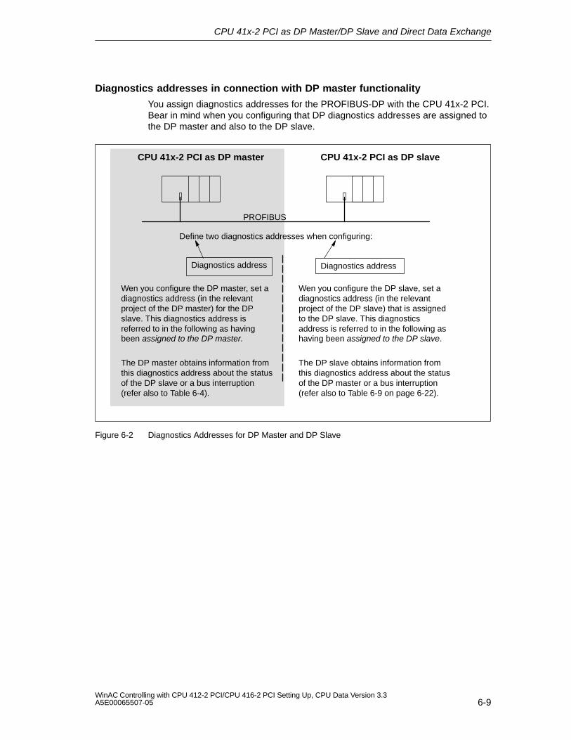
CPU 41x-2 PCI as DP Master/DP Slave and Direct Data Exchange
6-9WinAC Controlling with CPU 412-2 PCI/CPU 416-2 PCI Setting Up, CPU Data Version 3.3A5E00065507-05
Diagnostics addresses in connection with DP master functionality
You assign diagnostics addresses for the PROFIBUS-DP with the CPU 41x-2 PCI.Bear in mind when you configuring that DP diagnostics addresses are assigned tothe DP master and also to the DP slave.
Define two diagnostics addresses when configuring:
PROFIBUS
CPU 41x-2 PCI as DP slaveCPU 41x-2 PCI as DP master
Diagnostics address Diagnostics address
Wen you configure the DP master, set adiagnostics address (in the relevantproject of the DP master) for the DPslave. This diagnostics address isreferred to in the following as havingbeen assigned to the DP master.
Wen you configure the DP slave, set adiagnostics address (in the relevantproject of the DP slave) that is assignedto the DP slave. This diagnosticsaddress is referred to in the following ashaving been assigned to the DP slave.
The DP master obtains information fromthis diagnostics address about the statusof the DP slave or a bus interruption(refer also to Table 6-4).
The DP slave obtains information fromthis diagnostics address about the statusof the DP master or a bus interruption(refer also to Table 6-9 on page 6-22).
Figure 6-2 Diagnostics Addresses for DP Master and DP Slave
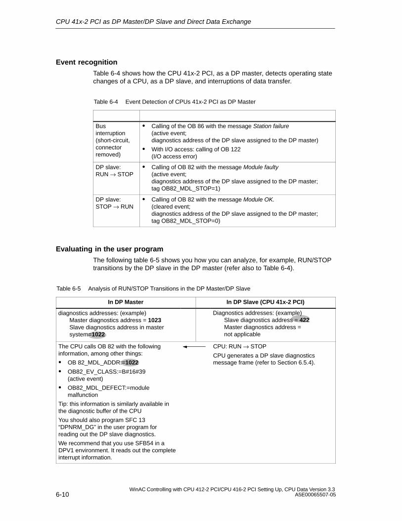
CPU 41x-2 PCI as DP Master/DP Slave and Direct Data Exchange
6-10WinAC Controlling with CPU 412-2 PCI/CPU 416-2 PCI Setting Up, CPU Data Version 3.3
A5E00065507-05
Event recognition
Table 6-4 shows how the CPU 41x-2 PCI, as a DP master, detects operating statechanges of a CPU, as a DP slave, and interruptions of data transfer.
Table 6-4 Event Detection of CPUs 41x-2 PCI as DP Master
Businterruption(short-circuit,connectorremoved)
Calling of the OB 86 with the message Station failure(active event; diagnostics address of the DP slave assigned to the DP master)
With I/O access: calling of OB 122 (I/O access error)
DP slave: RUN → STOP
Calling of OB 82 with the message Module faulty(active event; diagnostics address of the DP slave assigned to the DP master; tag OB82_MDL_STOP=1)
DP slave: STOP → RUN
Calling of OB 82 with the message Module OK.(cleared event; diagnostics address of the DP slave assigned to the DP master; tag OB82_MDL_STOP=0)
Evaluating in the user program
The following table 6-5 shows you how you can analyze, for example, RUN/STOPtransitions by the DP slave in the DP master (refer also to Table 6-4).
Table 6-5 Analysis of RUN/STOP Transitions in the DP Master/DP Slave
In DP Master In DP Slave (CPU 41x-2 PCI)
diagnostics addresses: (example)Master diagnostics address = 1023Slave diagnostics address in master system=1022
Diagnostics addresses: (example)Slave diagnostics address = 422Master diagnostics address = not applicable
The CPU calls OB 82 with the followinginformation, among other things:
OB 82_MDL_ADDR:=1022
OB82_EV_CLASS:=B#16#39(active event)
OB82_MDL_DEFECT:=modulemalfunction
Tip: this information is similarly available inthe diagnostic buffer of the CPU
You should also program SFC 13“DPNRM_DG” in the user program forreading out the DP slave diagnostics.
We recommend that you use SFB54 in aDPV1 environment. It reads out the completeinterrupt information.
CPU: RUN → STOP
CPU generates a DP slave diagnosticsmessage frame (refer to Section 6.5.4).
CPU 41x-2 PCI as DP Master/DP Slave and Direct Data Exchange
6-11WinAC Controlling with CPU 412-2 PCI/CPU 416-2 PCI Setting Up, CPU Data Version 3.3A5E00065507-05
6.4 CPU 41x-2 PCI as DP Slave
Introduction
In this chapter we describe the characteristics and technical specifications of theCPU when you are operating it as a DP slave.
You will find the characteristics and technical specifications of the CPUs in Section8.2 and 8.3.
Requirements
1. Only one DP interface of a CPU can be configured as a DP slave at any time.
2. Do you want the MPI/DP interface to be a DP interface? If so, you mustconfigure the interface as the DP interface.
You have to configure the CPU as the DP slave before starting to commission.This means that in STEP 7 you have to
– ”Enable” the CPU as a DP slave
– Assign a PROFIBUS address
– Assign a slave diagnostics address
– Define the address areas for data exchange with the DP master.
Device master (GSD) files
You require a device master file before you can configure the CPU as a DP slaveon a third–party system.
You can download the device master file from the Internet athttp://www.ad.siemens.de/csi_e/gsd.
Configuration and parameter assignment frame
When you configure/assign parameters to the CPU 41x-2 PCI, you are supportedby STEP 7. Should you require a description of the configuration and parameterassignment frame – say, for checking with a bus monitor – you will find thedescription of the configuration and parameter assignment frame on the Internet athttp://www.ad.siemens.de/simatic-cs; the contribution has the ID 1452338.
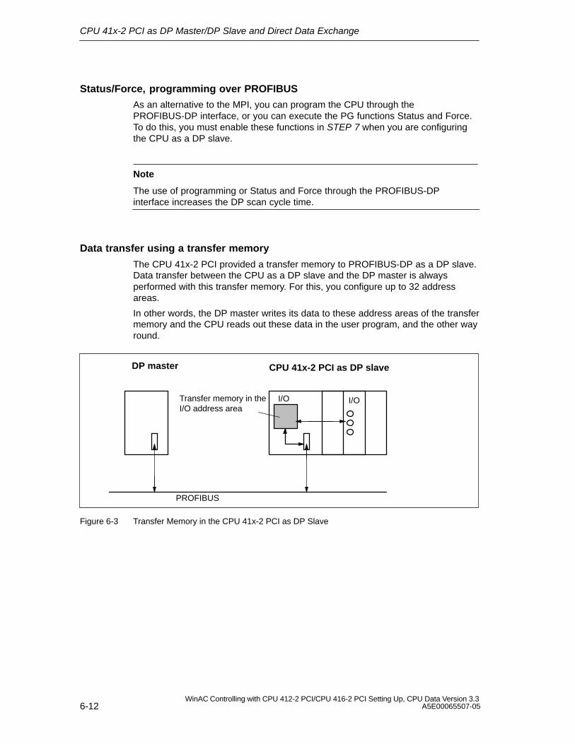
CPU 41x-2 PCI as DP Master/DP Slave and Direct Data Exchange
6-12WinAC Controlling with CPU 412-2 PCI/CPU 416-2 PCI Setting Up, CPU Data Version 3.3
A5E00065507-05
Status/Force, programming over PROFIBUS
As an alternative to the MPI, you can program the CPU through thePROFIBUS-DP interface, or you can execute the PG functions Status and Force.To do this, you must enable these functions in STEP 7 when you are configuringthe CPU as a DP slave.
Note
The use of programming or Status and Force through the PROFIBUS-DPinterface increases the DP scan cycle time.
Data transfer using a transfer memory
The CPU 41x-2 PCI provided a transfer memory to PROFIBUS-DP as a DP slave.Data transfer between the CPU as a DP slave and the DP master is alwaysperformed with this transfer memory. For this, you configure up to 32 addressareas.
In other words, the DP master writes its data to these address areas of the transfermemory and the CPU reads out these data in the user program, and the other wayround.
Transfer memory in theI/O address area
PROFIBUS
I/O
CPU 41x-2 PCI as DP slaveDP master
I/O
Figure 6-3 Transfer Memory in the CPU 41x-2 PCI as DP Slave
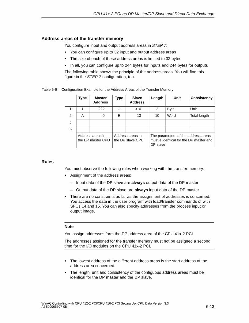
CPU 41x-2 PCI as DP Master/DP Slave and Direct Data Exchange
6-13WinAC Controlling with CPU 412-2 PCI/CPU 416-2 PCI Setting Up, CPU Data Version 3.3A5E00065507-05
Address areas of the transfer memory
You configure input and output address areas in STEP 7:
You can configure up to 32 input and output address areas
The size of each of these address areas is limited to 32 bytes
In all, you can configure up to 244 bytes for inputs and 244 bytes for outputs
The following table shows the principle of the address areas. You will find thisfigure in the STEP 7 configuration, too.
Table 6-6 Configuration Example for the Address Areas of the Transfer Memory
Type MasterAddress
Type SlaveAddress
Length Unit Consistency
1 I 222 O 310 2 Byte Unit
2 A 0 E 13 10 Word Total length
:
32
Address areas inthe DP master CPU
Address areas inthe DP slave CPU
The parameters of the address areasmust e identical for the DP master andDP slave
Rules
You must observe the following rules when working with the transfer memory:
Assignment of the address areas:
– Input data of the DP slave are always output data of the DP master
– Output data of the DP slave are always input data of the DP master
There are no constraints as far as the assignment of addresses is concerned.You access the data in the user program with load/transfer commands of withSFCs 14 and 15. You can also specify addresses from the process input oroutput image.
Note
You assign addresses form the DP address area of the CPU 41x-2 PCI.
The addresses assigned for the transfer memory must not be assigned a secondtime for the I/O modules on the CPU 41x-2 PCI.
The lowest address of the different address areas is the start address of theaddress area concerned.
The length, unit and consistency of the contiguous address areas must beidentical for the DP master and the DP slave.

CPU 41x-2 PCI as DP Master/DP Slave and Direct Data Exchange
6-14WinAC Controlling with CPU 412-2 PCI/CPU 416-2 PCI Setting Up, CPU Data Version 3.3
A5E00065507-05
S5 DP master
If you are using an IM 308-C as the DP master and the CPU 41x-2 PCI as a DPslave, the following applies to the exchange of consistent data:
You must program FB 192 for the IM 308-C so that consistent data can betransferred between the DP master and the DP slave. FB 192 is used to output orread out the data of the CPU 41x-2 PCI only as one complete block.
S5-95U as DP master
If you are using an AG S5-95U as the DP master, you must set its parameters forthe CPU 41x-2 PCI as a DP slave, too.
CPU 41x-2 PCI as DP Master/DP Slave and Direct Data Exchange
6-15WinAC Controlling with CPU 412-2 PCI/CPU 416-2 PCI Setting Up, CPU Data Version 3.3A5E00065507-05
Example program
Below, you will see the exchange of data between the DP master and DP slave ina short example program. In this example, you will meet up again with theaddresses which you first saw in Table 6-6.
In DP Slave CPU In DP Master CPU
L 2T MB 6L IB 0T MB 7
Data smoothingin DP slave
L FW 6T PAW 310
Forward data toDP master
L PEB 222T MB 50L PEB 223L B#16#3+ IT MB 51
Further processreceived data inDP master
L 10+ 3T MB 60
Data smoothingin DP master
CALL SFC 15 LADDR:= W#16#0 RECORD:= P#M60.0 Byte20 RET_VAL:= MW 22
Send data to DPslave
CALL SFC 14 LADDR:=W#16#D RET_VAL:=FW 20 RECORD:=P#M30.0 Byte20
Receive datafrom DP master
L MB 30L MB 7+ IT FW 100
Further processreceived data
Data transfer at STOP
The DP slave CPU goes to STOP: the data in the transfer memory of the CPU areoverwritten with “0” – in other words, the DP master reads “0”.
The DP master goes to STOP: The current data in the transfer memory of theCPU are retained and can still be read out from the CPU.
PROFIBUS address
You must not set the “126” as the PROFIBUS address for the CPU 41x-2 PCI as aDP slave.
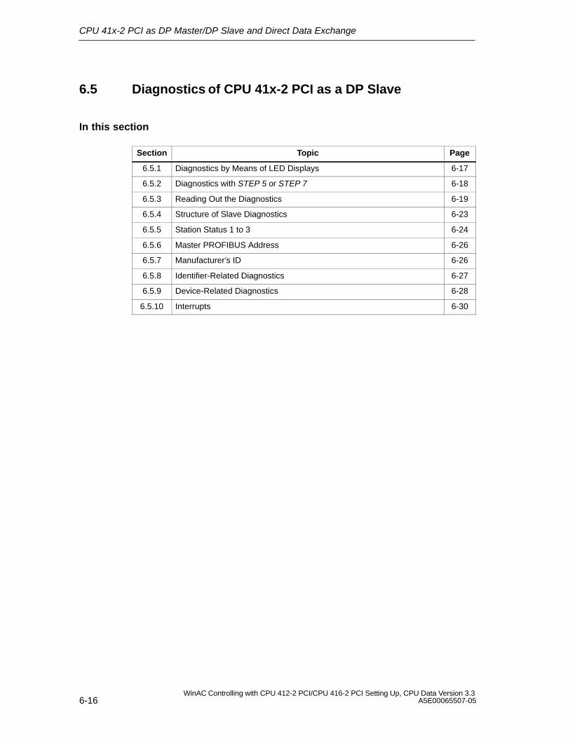
CPU 41x-2 PCI as DP Master/DP Slave and Direct Data Exchange
6-16WinAC Controlling with CPU 412-2 PCI/CPU 416-2 PCI Setting Up, CPU Data Version 3.3
A5E00065507-05
6.5 Diagnostics of CPU 41x-2 PCI as a DP Slave
In this section
Section Topic Page
6.5.1 Diagnostics by Means of LED Displays 6-17
6.5.2 Diagnostics with STEP 5 or STEP 7 6-18
6.5.3 Reading Out the Diagnostics 6-19
6.5.4 Structure of Slave Diagnostics 6-23
6.5.5 Station Status 1 to 3 6-24
6.5.6 Master PROFIBUS Address 6-26
6.5.7 Manufacturer’s ID 6-26
6.5.8 Identifier-Related Diagnostics 6-27
6.5.9 Device-Related Diagnostics 6-28
6.5.10 Interrupts 6-30
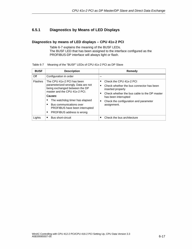
CPU 41x-2 PCI as DP Master/DP Slave and Direct Data Exchange
6-17WinAC Controlling with CPU 412-2 PCI/CPU 416-2 PCI Setting Up, CPU Data Version 3.3A5E00065507-05
6.5.1 Diagnostics by Means of LED Displays
Diagnostics by means of LED displays – CPU 41x-2 PCI
Table 6-7 explains the meaning of the BUSF LEDs.The BUSF LED that has been assigned to the interface configured as thePROFIBUS-DP interface will always light or flash.
Table 6-7 Meaning of the ”BUSF” LEDs of CPU 41x-2 PCI as DP Slave
BUSF Description Remedy
Off Configuration in order –
Flashes The CPU 41x-2 PCI has beenparameterized wrongly. Data are notbeing exchanged between the DPmaster and the CPU 41x-2 PCI.
Causes:
Check the CPU 41x-2 PCI
Check whether the bus connector has beeninserted properly
Check whether the bus cable to the DP masterCauses:
The watchdog timer has elapsed
Bus communications overPROFIBUS have been interrupted
PROFIBUS address is wrong
has been interrupted
Check the configuration and parameterassignment.
Lights Bus short-circuit Check the bus architecture
CPU 41x-2 PCI as DP Master/DP Slave and Direct Data Exchange
6-18WinAC Controlling with CPU 412-2 PCI/CPU 416-2 PCI Setting Up, CPU Data Version 3.3
A5E00065507-05
6.5.2 Diagnostics with STEP 5 or STEP 7
Slave diagnostics
The slave diagnostics conforms to standard EN 50170, Volume 2, PROFIBUS. Itcan be read out as a function of the DP master for all DP slaves conforming to thestandard with STEP 5 or STEP 7.
The following sections describe how the slave diagnostics is read out and how it isstructured.
S7 diagnostics
A S7 diagnostics can be requested in the user program by all modules in theSIMATIC S7/M7 range of modules with diagnostics capability. To determinewhether a module has diagnostics capability, you can refer to the information aboutthe module or to the catalog. The structure of the S7 diagnostics is identical forcentrally and distributed plugged module.
The diagnostic data of a module are located in data records 0 and 1 of the systemdata area of the module. Data record 0 contains 4 bytes of diagnostic data, whichdescribe the current status of a module. Data record 1 additionally containsboard-specific diagnostic data.
You will find the structure of the diagnostic data in the reference manual Standardand System Functions.
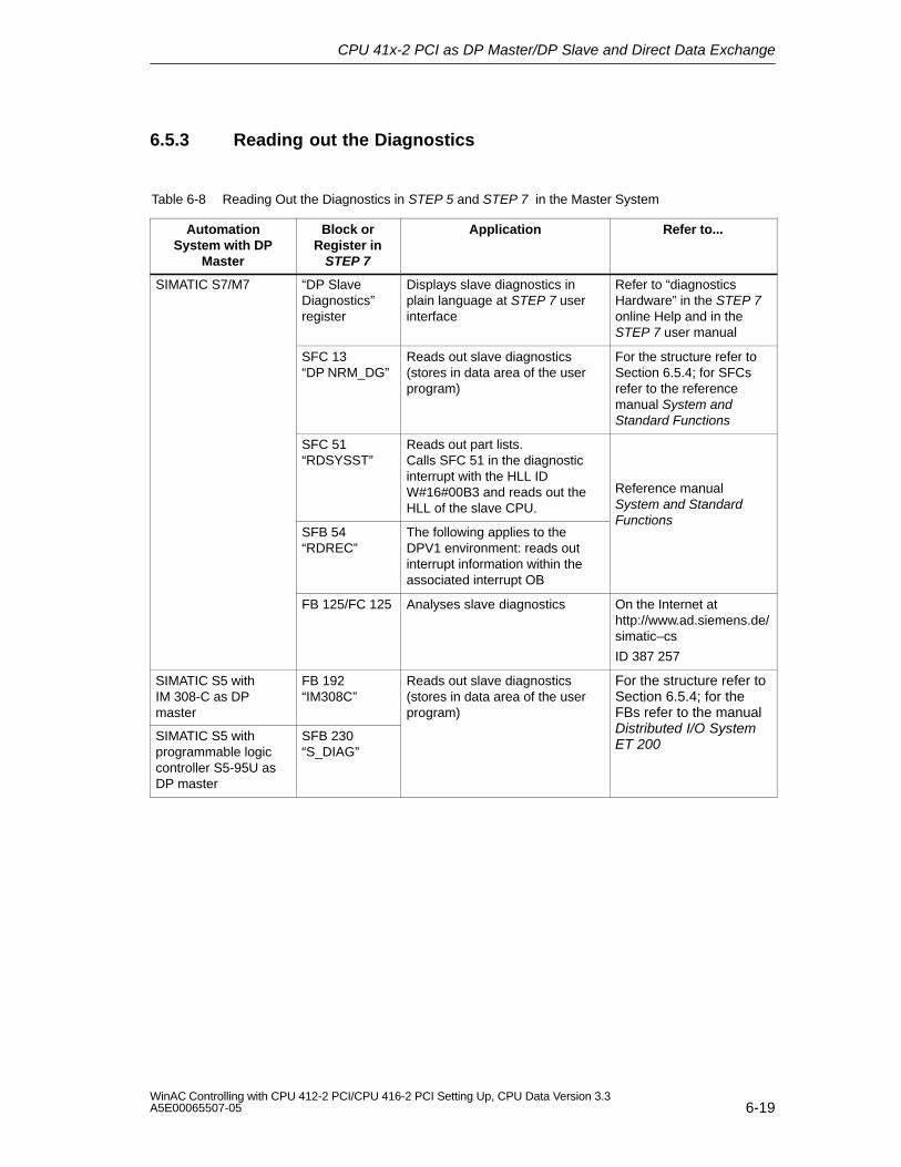
CPU 41x-2 PCI as DP Master/DP Slave and Direct Data Exchange
6-19WinAC Controlling with CPU 412-2 PCI/CPU 416-2 PCI Setting Up, CPU Data Version 3.3A5E00065507-05
6.5.3 Reading out the Diagnostics
Table 6-8 Reading Out the Diagnostics in STEP 5 and STEP 7 in the Master System
AutomationSystem with DP
Master
Block orRegister in
STEP 7
Application Refer to...
SIMATIC S7/M7 “DP SlaveDiagnostics”register
Displays slave diagnostics inplain language at STEP 7 userinterface
Refer to “diagnosticsHardware” in the STEP 7online Help and in theSTEP 7 user manual
SFC 13“DP NRM_DG”
Reads out slave diagnostics(stores in data area of the userprogram)
For the structure refer toSection 6.5.4; for SFCsrefer to the referencemanual System andStandard Functions
SFC 51“RDSYSST”
Reads out part lists.Calls SFC 51 in the diagnosticinterrupt with the HLL IDW#16#00B3 and reads out theHLL of the slave CPU.
Reference manualSystem and Standard
SFB 54“RDREC”
The following applies to theDPV1 environment: reads outinterrupt information within theassociated interrupt OB
Functions
FB 125/FC 125 Analyses slave diagnostics On the Internet athttp://www.ad.siemens.de/simatic–cs
ID 387 257
SIMATIC S5 withIM 308-C as DPmaster
FB 192“IM308C”
Reads out slave diagnostics (stores in data area of the userprogram)
For the structure refer toSection 6.5.4; for theFBs refer to the manual
SIMATIC S5 withprogrammable logiccontroller S5-95U asDP master
SFB 230“S_DIAG”
Distributed I/O SystemET 200
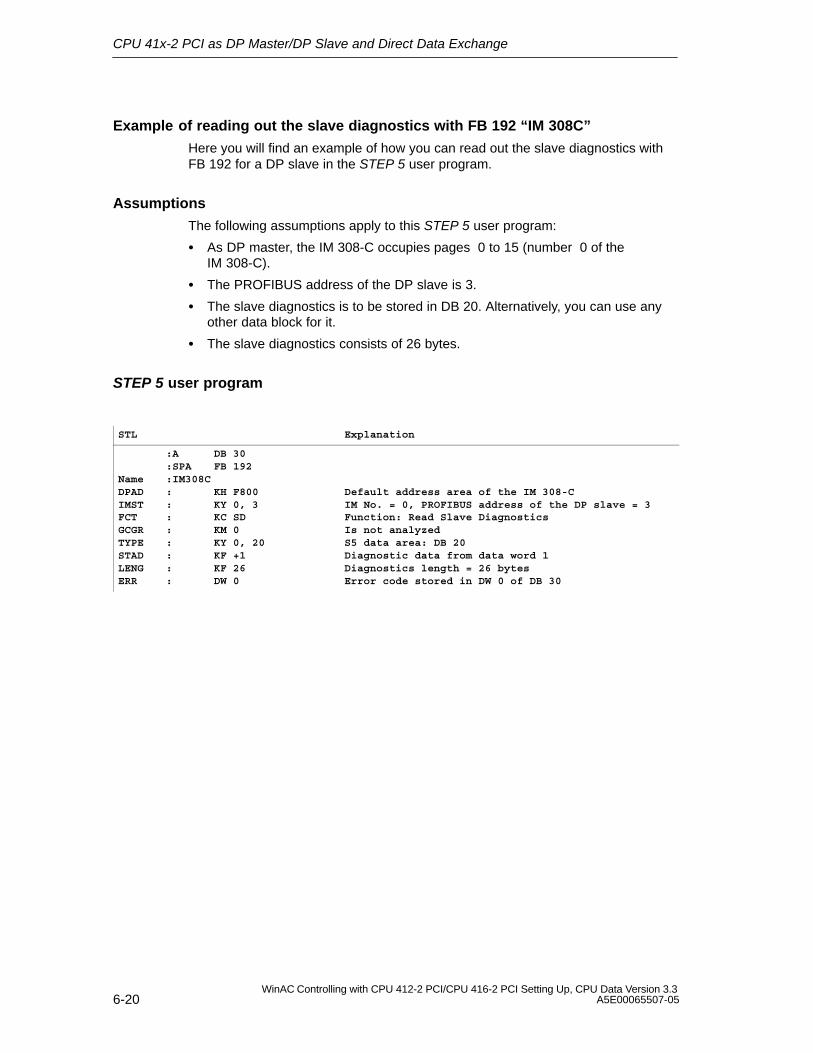
CPU 41x-2 PCI as DP Master/DP Slave and Direct Data Exchange
6-20WinAC Controlling with CPU 412-2 PCI/CPU 416-2 PCI Setting Up, CPU Data Version 3.3
A5E00065507-05
Example of reading out the slave diagnostics with FB 192 “IM 308C”
Here you will find an example of how you can read out the slave diagnostics withFB 192 for a DP slave in the STEP 5 user program.
Assumptions
The following assumptions apply to this STEP 5 user program:
As DP master, the IM 308-C occupies pages 0 to 15 (number 0 of theIM 308-C).
The PROFIBUS address of the DP slave is 3.
The slave diagnostics is to be stored in DB 20. Alternatively, you can use anyother data block for it.
The slave diagnostics consists of 26 bytes.
STEP 5 user program
STL Explanation
:A DB 30:SPA FB 192
Name :IM308CDPAD : KH F800IMST : KY 0, 3FCT : KC SDGCGR : KM 0TYPE : KY 0, 20STAD : KF +1LENG : KF 26ERR : DW 0
Default address area of the IM 308-CIM No. = 0, PROFIBUS address of the DP slave = 3Function: Read Slave DiagnosticsIs not analyzedS5 data area: DB 20Diagnostic data from data word 1Diagnostics length = 26 bytesError code stored in DW 0 of DB 30
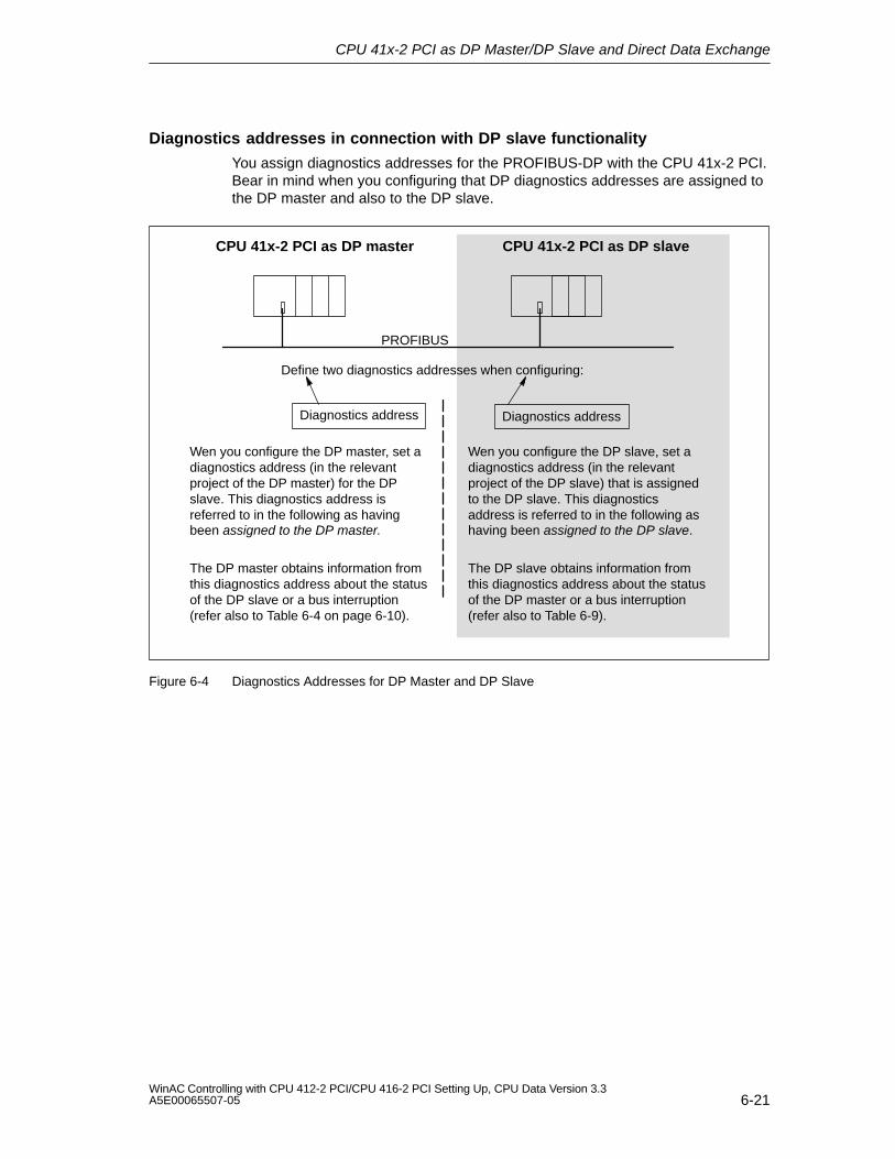
CPU 41x-2 PCI as DP Master/DP Slave and Direct Data Exchange
6-21WinAC Controlling with CPU 412-2 PCI/CPU 416-2 PCI Setting Up, CPU Data Version 3.3A5E00065507-05
Diagnostics addresses in connection with DP slave functionality
You assign diagnostics addresses for the PROFIBUS-DP with the CPU 41x-2 PCI.Bear in mind when you configuring that DP diagnostics addresses are assigned tothe DP master and also to the DP slave.
Define two diagnostics addresses when configuring:
PROFIBUS
CPU 41x-2 PCI as DP slaveCPU 41x-2 PCI as DP master
Diagnostics address Diagnostics address
Wen you configure the DP master, set adiagnostics address (in the relevantproject of the DP master) for the DPslave. This diagnostics address isreferred to in the following as havingbeen assigned to the DP master.
Wen you configure the DP slave, set adiagnostics address (in the relevantproject of the DP slave) that is assignedto the DP slave. This diagnosticsaddress is referred to in the following ashaving been assigned to the DP slave.
The DP master obtains information fromthis diagnostics address about the statusof the DP slave or a bus interruption(refer also to Table 6-4 on page 6-10).
The DP slave obtains information fromthis diagnostics address about the statusof the DP master or a bus interruption(refer also to Table 6-9).
Figure 6-4 Diagnostics Addresses for DP Master and DP Slave
CPU 41x-2 PCI as DP Master/DP Slave and Direct Data Exchange
6-22WinAC Controlling with CPU 412-2 PCI/CPU 416-2 PCI Setting Up, CPU Data Version 3.3
A5E00065507-05
Event recognition
Table 6-9 shows how the CPU 41x-2 PCI, as a DP slave, detects operating statechanges and interruptions of data transfer.
Table 6-9 Event Detection of CPUs 41x-2 PCI as DP Slave
Bus interruption(short-circuit,connector removed)
Calling of the OB 86 with the message Station failure(active event; diagnostics address of the DP slave assignedto the DP slave)
With I/O access: calling of OB 122 (I/O access error)
DP master: RUN → STOP
Calling of OB 82 with the message Module faulty(active event; diagnostics address of the DP slave assigned to the DPslave; tag OB82_MDL_STOP=1)
DP master: STOP → RUN
Calling of OB 82 with the message Module OK.(cleared event; diagnostics address of the DP slave assigned to the DPslave; tag OB82_MDL_STOP=0)
Evaluating in the user program
The following table 6-10 shows you how you can analyze, for example, RUN/STOPtransitions by the DP master in the DP slave (refer also to Table 6-9).
Table 6-10 Analysis of RUN/STOP Transitions in the DP Master/DP Slave
In DP Master In DP Slave
Diagnostics addresses: (example)Master diagnostics address = 1023Slave diagnostics address in master system=1022
Diagnostics addresses: (example)Slave diagnostics address = 422Master diagnostics address = not applicable
CPU: RUN → STOP The CPU calls OB 82 with the followinginformation, among other things:
OB 82_MDL_ADDR:=422
OB82_EV_CLASS:=B#16#39(active event)
OB82_MDL_DEFECT:=modulemalfunction
Tip: this information is similarly available inthe diagnostic buffer of the CPU
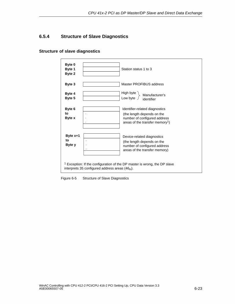
CPU 41x-2 PCI as DP Master/DP Slave and Direct Data Exchange
6-23WinAC Controlling with CPU 412-2 PCI/CPU 416-2 PCI Setting Up, CPU Data Version 3.3A5E00065507-05
6.5.4 Structure of Slave Diagnostics
Structure of slave diagnostics
Byte 0Byte 1 Station status 1 to 3Byte 2
Byte 3 Master PROFIBUS address
Byte 4Byte 5 Low byte
High byteManufacturer’sidentifier
Byte 6to
Identifier-related diagnostics
Byte x
Device-related diagnostics...
.
.
.
Byte x+1toByte y
(the length depends on thenumber of configured addressareas of the transfer memory1)
(the length depends on thenumber of configured addressareas of the transfer memory)
1 Exception: If the configuration of the DP master is wrong, the DP slaveinterprets 35 configured address areas (46H).
Figure 6-5 Structure of Slave Diagnostics
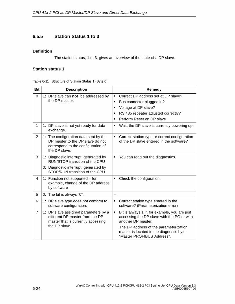
CPU 41x-2 PCI as DP Master/DP Slave and Direct Data Exchange
6-24WinAC Controlling with CPU 412-2 PCI/CPU 416-2 PCI Setting Up, CPU Data Version 3.3
A5E00065507-05
6.5.5 Station Status 1 to 3
Definition
The station status, 1 to 3, gives an overview of the state of a DP slave.
Station status 1
Table 6-11 Structure of Station Status 1 (Byte 0)
Bit Description Remedy
0 1: DP slave can not be addressed bythe DP master.
Correct DP address set at DP slave?
Bus connector plugged in?
Voltage at DP slave?
RS 485 repeater adjusted correctly?
Perform Reset on DP slave
1 1: DP slave is not yet ready for dataexchange.
Wait, the DP slave is currently powering up.
2 1: The configuration data sent by theDP master to the DP slave do notcorrespond to the configuration ofthe DP slave.
Correct station type or correct configurationof the DP slave entered in the software?
3 1: Diagnostic interrupt, generated by RUN/STOP transition of the CPU
0: Diagnostic interrupt, generated by STOP/RUN transition of the CPU
You can read out the diagnostics.
4 1: Function not supported – forexample, change of the DP addressby software
Check the configuration.
5 0: The bit is always “0”. –
6 1: DP slave type does not conform tosoftware configuration.
Correct station type entered in thesoftware? (Parameterization error)
7 1: DP slave assigned parameters by adifferent DP master from the DPmaster that is currently accessingthe DP slave.
Bit is always 1 if, for example, you are justaccessing the DP slave with the PG or withanother DP master.
The DP address of the parameterizationmaster is located in the diagnostic byte”Master PROFIBUS Address”.
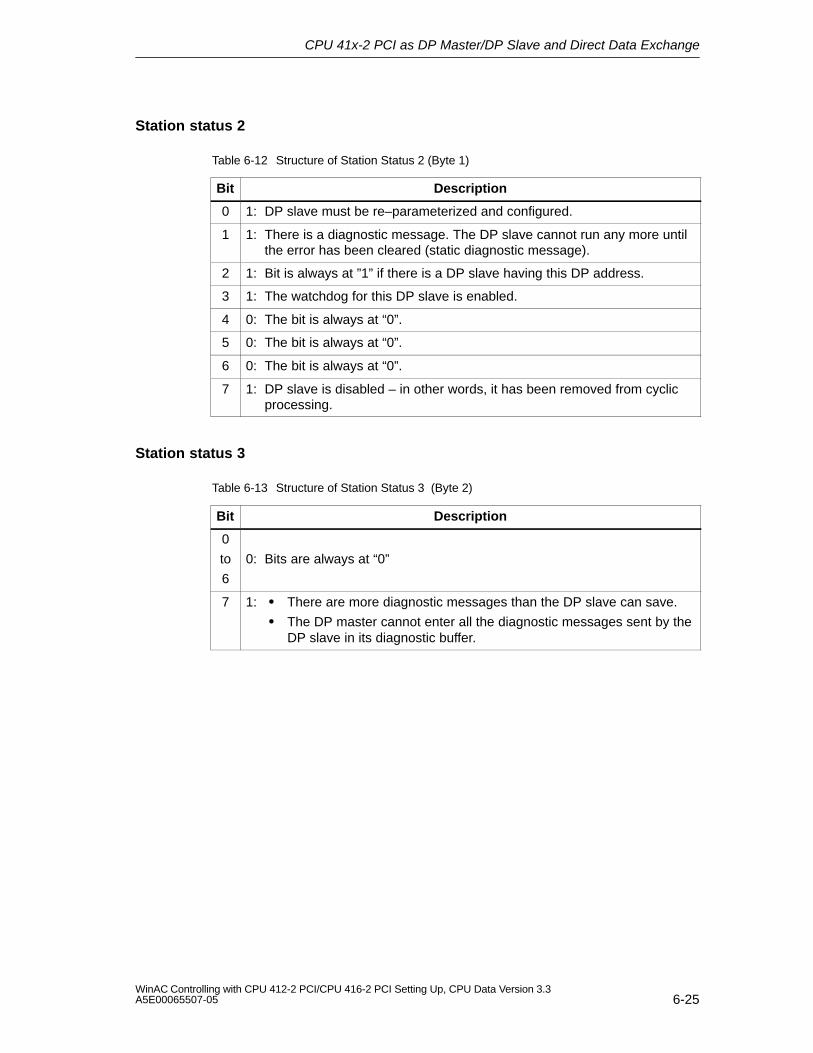
CPU 41x-2 PCI as DP Master/DP Slave and Direct Data Exchange
6-25WinAC Controlling with CPU 412-2 PCI/CPU 416-2 PCI Setting Up, CPU Data Version 3.3A5E00065507-05
Station status 2
Table 6-12 Structure of Station Status 2 (Byte 1)
Bit Description
0 1: DP slave must be re–parameterized and configured.
1 1: There is a diagnostic message. The DP slave cannot run any more untilthe error has been cleared (static diagnostic message).
2 1: Bit is always at ”1” if there is a DP slave having this DP address.
3 1: The watchdog for this DP slave is enabled.
4 0: The bit is always at “0”.
5 0: The bit is always at “0”.
6 0: The bit is always at “0”.
7 1: DP slave is disabled – in other words, it has been removed from cyclicprocessing.
Station status 3
Table 6-13 Structure of Station Status 3 (Byte 2)
Bit Description
0
to
6
0: Bits are always at “0”
7 1: There are more diagnostic messages than the DP slave can save.
The DP master cannot enter all the diagnostic messages sent by theDP slave in its diagnostic buffer.
CPU 41x-2 PCI as DP Master/DP Slave and Direct Data Exchange
6-26WinAC Controlling with CPU 412-2 PCI/CPU 416-2 PCI Setting Up, CPU Data Version 3.3
A5E00065507-05
6.5.6 Master PROFIBUS Address
Definition
The diagnostic byte Master PROFIBUS Address stores the DP address of the DPmaster which:
has parameterized the DP slave; and
has read and write access to the DP slave
Master PROFIBUS address
Table 6-14 Structure of the Master PROFIBUS Address (Byte 3)
0 to 7 DP address of the DP master that parameterized the DP slave andhas read and write access to the DP slave.
FFH: DP slave has not been parameterized by any DP master.
6.5.7 Manufacturer ’s ID
Definition
The manufacturer’s ID stores a code, which describes the type of the DP slave.
Manufacturer’s ID
Table 6-15 Structure of the Manufacturer’s ID (Bytes 4, 5)
80H CEH CPU 412-2 PCI
80H CFH CPU 416-2 PCI
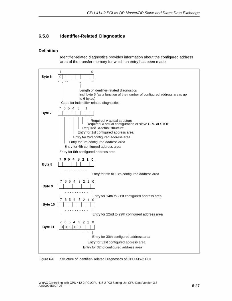
CPU 41x-2 PCI as DP Master/DP Slave and Direct Data Exchange
6-27WinAC Controlling with CPU 412-2 PCI/CPU 416-2 PCI Setting Up, CPU Data Version 3.3A5E00065507-05
6.5.8 Identifier-Related Diagnostics
Definition
Identifier-related diagnostics provides information about the configured addressarea of the transfer memory for which an entry has been made.
Byte 67 0
Length of identifier-related diagnostics incl. byte 6 (as a function of the number of configured address areas upto 6 bytes)
Byte 7
Required actual configuration or slave CPU at STOP
Entry for 2nd configured address areaEntry for 3rd configured address area
Entry for 4th configured address area
Entry for 5th configured address area
Entry for 6th to 13th configured address area
Code for indentifier-related diagnostics
0 1
7 6 5 4 1
02 1
3
Entry for 1st configured address area
7 6 5 4 3
Byte 11
Entry for 30th configured address area
Entry for 31st configured address area
02 17 6 5 4 3
02 17 6 5 4 3
Byte 802 17 6 5 4 3
Byte 9
Entry for 14th to 21st configured address area
02 17 6 5 4 3
Byte 10
Entry for 22nd to 29th configured address area
02 17 6 5 4 3
Entry for 32nd configured address area
00 00 0
Required actual structure
Required actual structure
Figure 6-6 Structure of Identifier-Related Diagnostics of CPU 41x-2 PCI
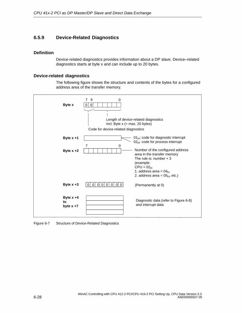
CPU 41x-2 PCI as DP Master/DP Slave and Direct Data Exchange
6-28WinAC Controlling with CPU 412-2 PCI/CPU 416-2 PCI Setting Up, CPU Data Version 3.3
A5E00065507-05
6.5.9 Device-Related Diagnostics
Definition
Device-related diagnostics provides information about a DP slave. Device–relateddiagnostics starts at byte x and can include up to 20 bytes.
Device-related diagnostics
The following figure shows the structure and contents of the bytes for a configuredaddress area of the transfer memory.
Byte x +1 01H: code for diagnostic interrupt02H: code for process interrupt
Byte x +4tobyte x +7
Byte x7 0
Length of device-related diagnostics incl. Byte x (= max. 20 bytes)
Code for device-related diagnostics
0 0
6
Byte x +2
Byte x +3
Number of the configured addressarea in the transfer memoryThe rule is: number + 3(example:CPU = 02H1. address area = 04H2. address area = 05H, etc.)
(Permanently at 0)
Diagnostic data (refer to Figure 6-8)and interrupt data
7 0
0 0 0 0 0 0 0 0
Figure 6-7 Structure of Device-Related Diagnostics
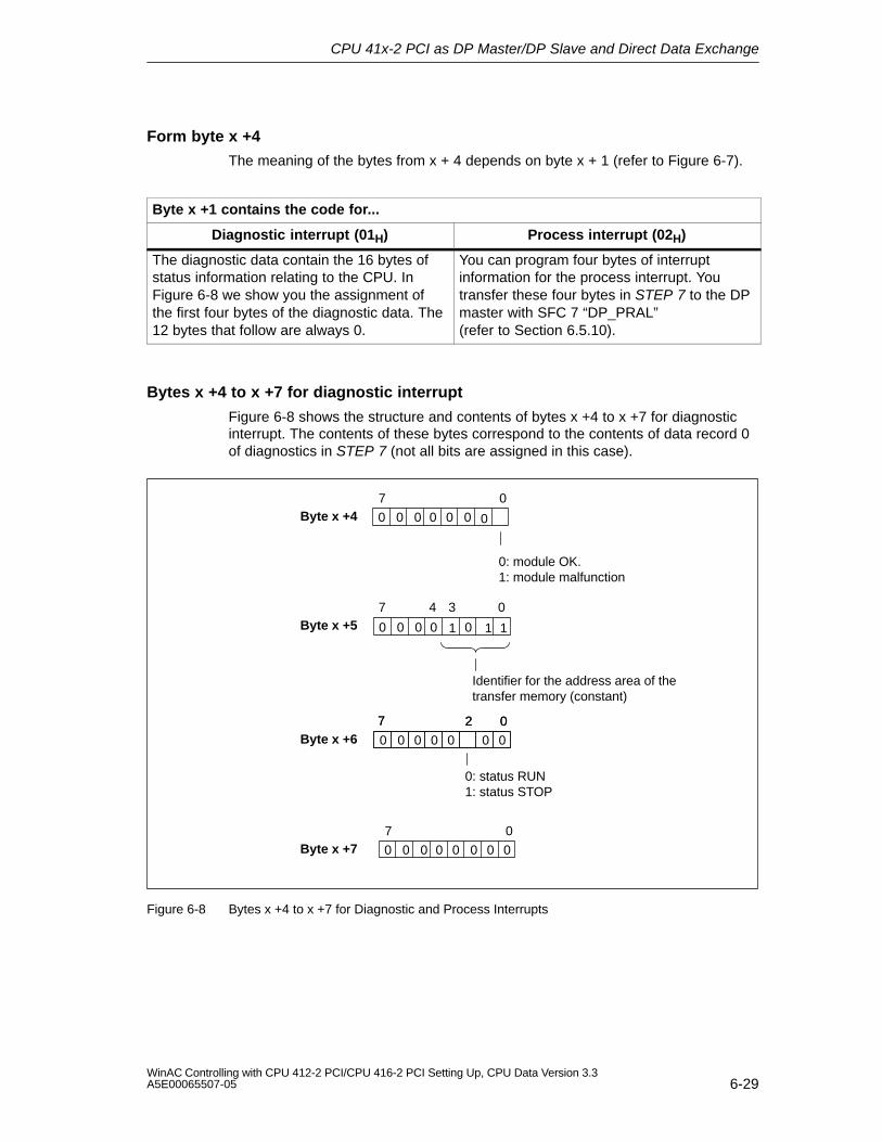
CPU 41x-2 PCI as DP Master/DP Slave and Direct Data Exchange
6-29WinAC Controlling with CPU 412-2 PCI/CPU 416-2 PCI Setting Up, CPU Data Version 3.3A5E00065507-05
Form byte x +4
The meaning of the bytes from x + 4 depends on byte x + 1 (refer to Figure 6-7).
Byte x +1 contains the code for...
Diagnostic interrupt (01H) Process interrupt (02H)
The diagnostic data contain the 16 bytes ofstatus information relating to the CPU. InFigure 6-8 we show you the assignment ofthe first four bytes of the diagnostic data. The12 bytes that follow are always 0.
You can program four bytes of interruptinformation for the process interrupt. Youtransfer these four bytes in STEP 7 to the DPmaster with SFC 7 “DP_PRAL” (refer to Section 6.5.10).
Bytes x +4 to x +7 for diagnostic interrupt
Figure 6-8 shows the structure and contents of bytes x +4 to x +7 for diagnosticinterrupt. The contents of these bytes correspond to the contents of data record 0of diagnostics in STEP 7 (not all bits are assigned in this case).
Byte x +47 0
Byte x +5
Byte x +6
0: status RUN1: status STOP
0: module OK.1: module malfunction
0
1
0 0 0 0
1
7 4 0
02
3
7 027
0 0
0 0 00 01
Identifier for the address area of thetransfer memory (constant)
0000000
Byte x +77 0
0 0 0 0 00 0 0
Figure 6-8 Bytes x +4 to x +7 for Diagnostic and Process Interrupts
CPU 41x-2 PCI as DP Master/DP Slave and Direct Data Exchange
6-30WinAC Controlling with CPU 412-2 PCI/CPU 416-2 PCI Setting Up, CPU Data Version 3.3
A5E00065507-05
6.5.10 Interrupts
Interrupts with S7/M7 DP master
In CPU 41x-2 PCI as a DP slave, you can trigger a process interrupt on theDP master in the user program. By calling SFC 7 “DP_PRAL”, you trigger anOB 40 in the user program of the DP master. Using SFC 7, you can forwardinterrupt information in a double word to the DP master, it being possible for you toanalyze the information in OB 40, in tag OB40_POINT_ADDR. You can programthe interrupt information. You will find a detailed description of SFC 7 “DP_PRAL”in the reference manual System Software for S7-300/400 - System and StandardFunctions.
Interrupts with a different DP master
Should you operate the CPU 41x-2 PCI with a different DP master, these interruptsare simulated within the device–related diagnostics of the CPU 41x-2 PCI. Youmust process the corresponding diagnostics events in the user program of theDP master.
Note
In order to be able to analyze the diagnostic interrupt and the process interrupt bymeans of device-related diagnostics with a different DP master, you must takenote of the following:
The DP master should be capable of storing the diagnostic messages – inother words, the diagnostic messages should be stored in a ring buffer withinthe DP master. If the DP master cannot save the diagnostic messages, onlythe last diagnostic message to be received will ever be stored, for example.
You must query the corresponding bits in the device–related diagnostics on aregular basis in your user program. When doing so, you must also take the bustransit time of PROFIBUS-DP into account so that you can query the bits, say,at least once synchronously with the bus transit time.
Using an IM 308-C as a DP master, you cannot use process interrupts withinthe device-related diagnostics, since only active – not cleared – interrupts arereported.
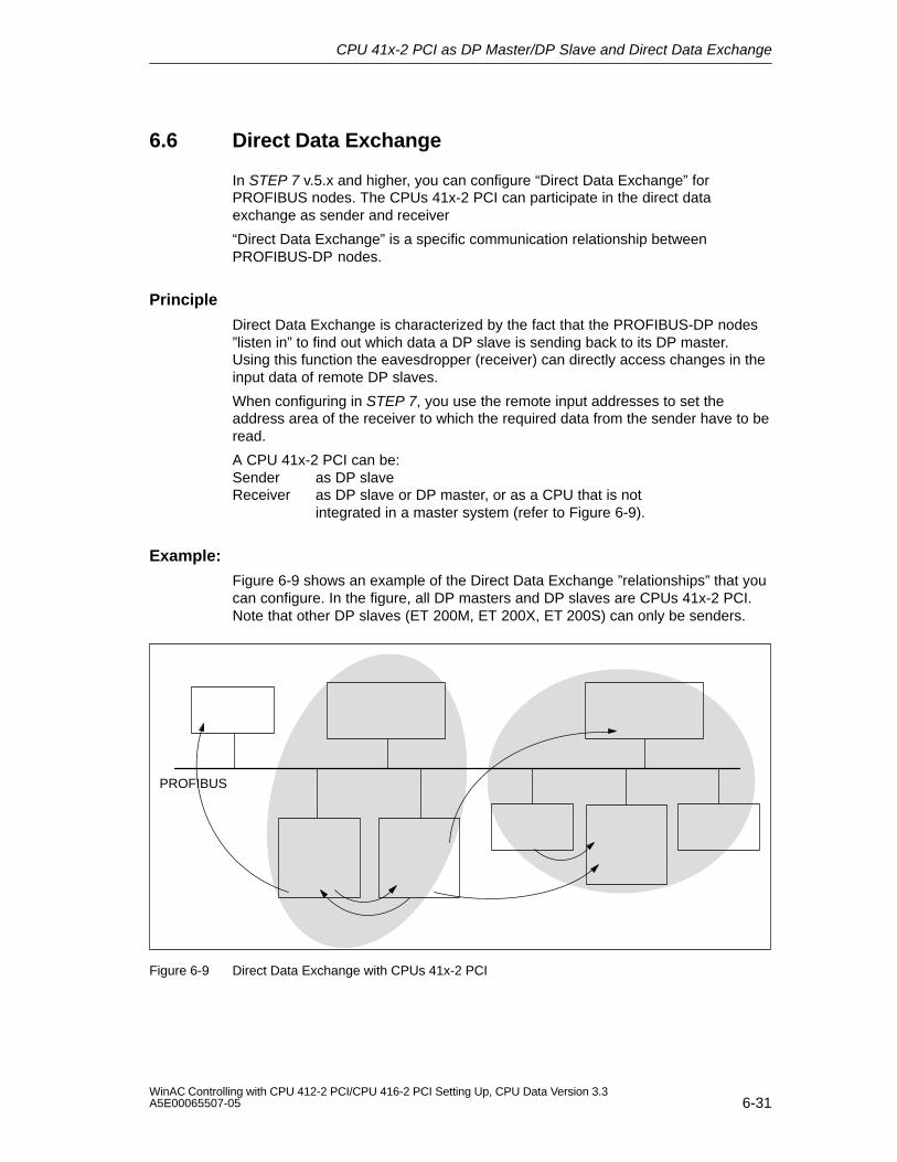
CPU 41x-2 PCI as DP Master/DP Slave and Direct Data Exchange
6-31WinAC Controlling with CPU 412-2 PCI/CPU 416-2 PCI Setting Up, CPU Data Version 3.3A5E00065507-05
6.6 Direct Data Exchange
In STEP 7 v.5.x and higher, you can configure “Direct Data Exchange” forPROFIBUS nodes. The CPUs 41x-2 PCI can participate in the direct dataexchange as sender and receiver
“Direct Data Exchange” is a specific communication relationship betweenPROFIBUS-DP nodes.
Principle
Direct Data Exchange is characterized by the fact that the PROFIBUS-DP nodes”listen in” to find out which data a DP slave is sending back to its DP master.Using this function the eavesdropper (receiver) can directly access changes in theinput data of remote DP slaves.
When configuring in STEP 7, you use the remote input addresses to set theaddress area of the receiver to which the required data from the sender have to beread.
A CPU 41x-2 PCI can be:Sender as DP slaveReceiver as DP slave or DP master, or as a CPU that is not
integrated in a master system (refer to Figure 6-9).
Example:
Figure 6-9 shows an example of the Direct Data Exchange ”relationships” that youcan configure. In the figure, all DP masters and DP slaves are CPUs 41x-2 PCI.Note that other DP slaves (ET 200M, ET 200X, ET 200S) can only be senders.
PROFIBUS
Figure 6-9 Direct Data Exchange with CPUs 41x-2 PCI
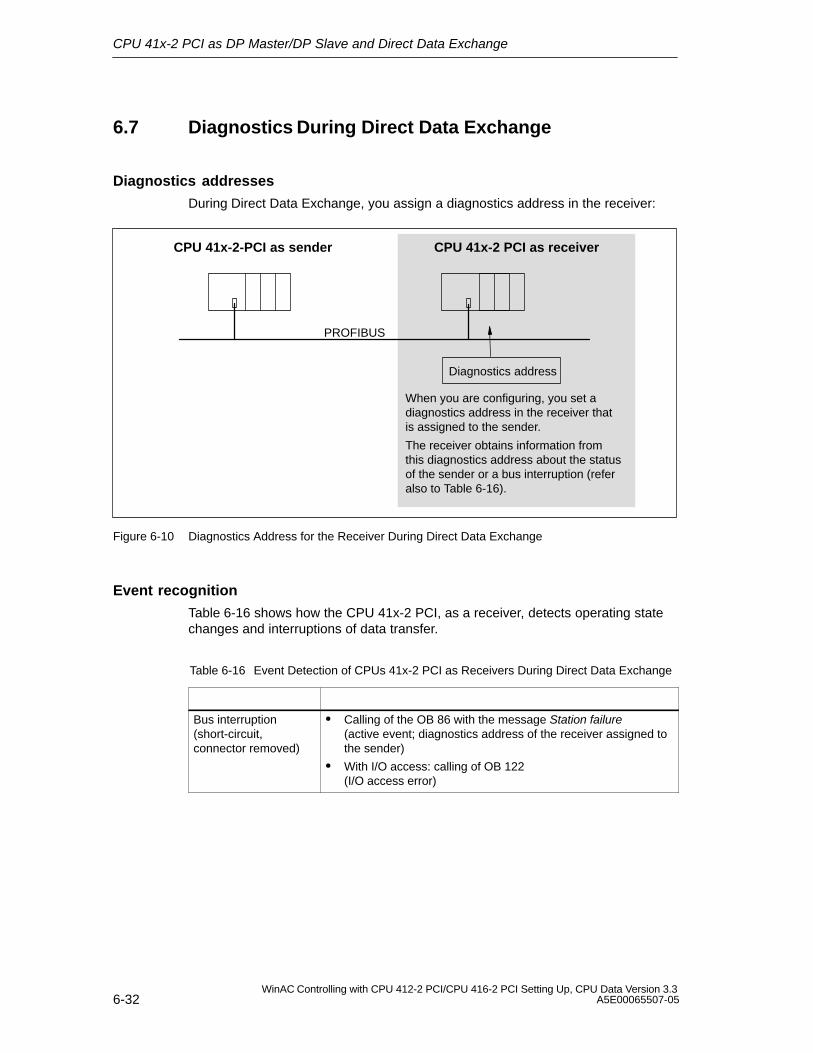
CPU 41x-2 PCI as DP Master/DP Slave and Direct Data Exchange
6-32WinAC Controlling with CPU 412-2 PCI/CPU 416-2 PCI Setting Up, CPU Data Version 3.3
A5E00065507-05
6.7 Diagnostics During Direct Data Exchange
Diagnostics addresses
During Direct Data Exchange, you assign a diagnostics address in the receiver:
PROFIBUS
CPU 41x-2 PCI as receiverCPU 41x-2-PCI as sender
Diagnostics address
When you are configuring, you set adiagnostics address in the receiver thatis assigned to the sender.
The receiver obtains information fromthis diagnostics address about the statusof the sender or a bus interruption (referalso to Table 6-16).
Figure 6-10 Diagnostics Address for the Receiver During Direct Data Exchange
Event recognition
Table 6-16 shows how the CPU 41x-2 PCI, as a receiver, detects operating statechanges and interruptions of data transfer.
Table 6-16 Event Detection of CPUs 41x-2 PCI as Receivers During Direct Data Exchange
Bus interruption(short-circuit,connector removed)
Calling of the OB 86 with the message Station failure(active event; diagnostics address of the receiver assigned tothe sender)
With I/O access: calling of OB 122 (I/O access error)
CPU 41x-2 PCI as DP Master/DP Slave and Direct Data Exchange
6-33WinAC Controlling with CPU 412-2 PCI/CPU 416-2 PCI Setting Up, CPU Data Version 3.3A5E00065507-05
Evaluating in the user program
The following table 6-17 shows you how you can analyze, for example, a stationfailure of the sender in the receiver (refer also to Table 6-16).
Table 6-17 Analysis of a Station Failure of the Sender During Direct Data Exchange
In Sender In Receiver
Diagnostics addresses: (example)Master diagnostics address = 1023Slave diagnostics address in master system=1022
Diagnostics address: (example)Diagnostics address=444
Station failure The CPU calls OB 86 with the followinginformation, among other things:
OB 86_MDL_ADDR:=444
OB86_EV_CLASS:=B#16#38(active event)
OB86_FLT_ID:=B#16#C4 (failure of a DP station)
Tip: this information is similarly available inthe diagnostic buffer of the CPU

CPU 41x-2 PCI as DP Master/DP Slave and Direct Data Exchange
6-34WinAC Controlling with CPU 412-2 PCI/CPU 416-2 PCI Setting Up, CPU Data Version 3.3
A5E00065507-05
Time Synchronization (WinACTimeSync)
7-1WinAC Controlling with CPU 412-2 PCI/CPU 416-2 PCI Setting Up, CPU Data Version 3.3A5E00065507-05
Time Synchronization (WinACTimeSync)
In this chapter
Section Contents Page
7.1 Overview 7-2
7.2 Assigning a CP to Time Synchronization 7-4
7.3 Using the Time Synchronization Service 7-8
7.4 User Example 7-10
7
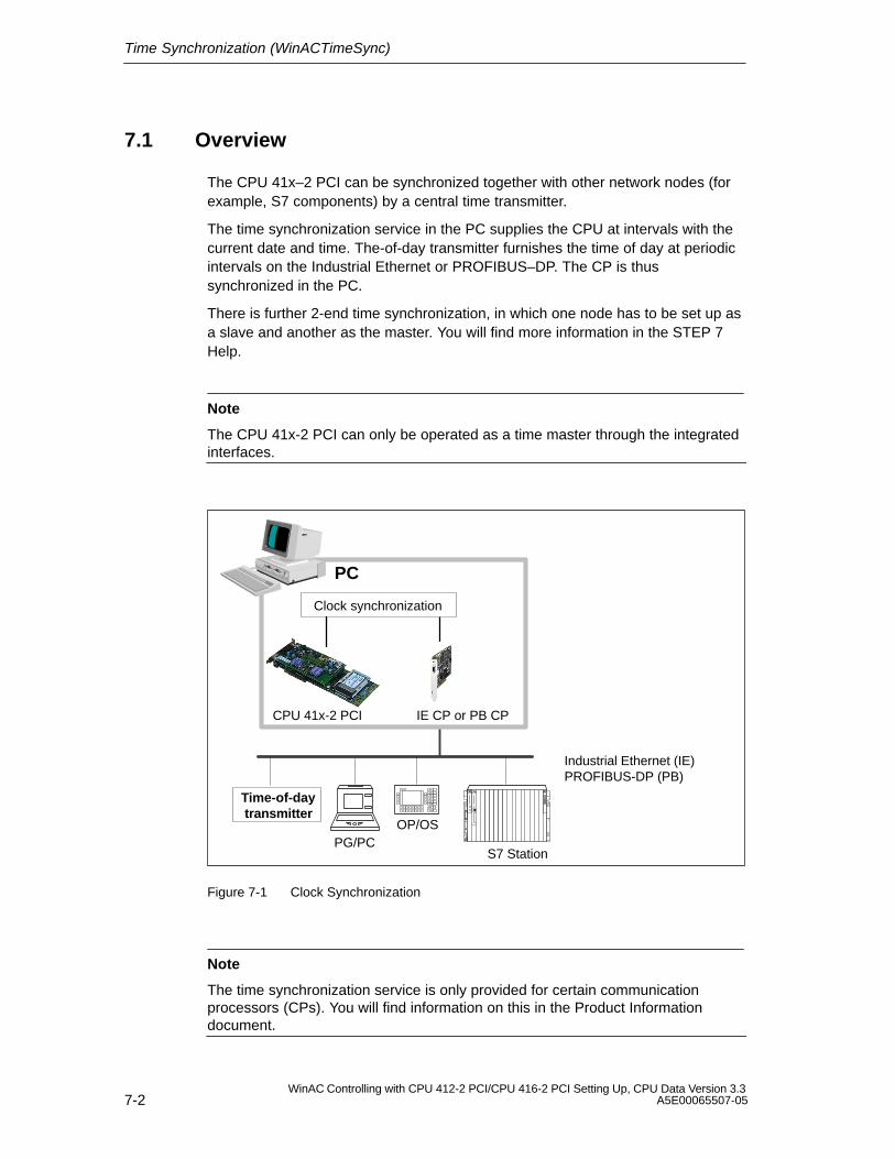
Time Synchronization (WinACTimeSync)
7-2WinAC Controlling with CPU 412-2 PCI/CPU 416-2 PCI Setting Up, CPU Data Version 3.3
A5E00065507-05
7.1 Overview
The CPU 41x–2 PCI can be synchronized together with other network nodes (forexample, S7 components) by a central time transmitter.
The time synchronization service in the PC supplies the CPU at intervals with thecurrent date and time. The-of-day transmitter furnishes the time of day at periodicintervals on the Industrial Ethernet or PROFIBUS–DP. The CP is thussynchronized in the PC.
There is further 2-end time synchronization, in which one node has to be set up asa slave and another as the master. You will find more information in the STEP 7Help.
Note
The CPU 41x-2 PCI can only be operated as a time master through the integratedinterfaces.
Time-of-day transmitter
Clock synchronization
PC
Industrial Ethernet (IE)PROFIBUS-DP (PB)
OP/OS
S7 StationPG/PC
CPU 41x-2 PCI IE CP or PB CP
Figure 7-1 Clock Synchronization
Note
The time synchronization service is only provided for certain communicationprocessors (CPs). You will find information on this in the Product Informationdocument.
Time Synchronization (WinACTimeSync)
7-3WinAC Controlling with CPU 412-2 PCI/CPU 416-2 PCI Setting Up, CPU Data Version 3.3A5E00065507-05
Requirements
The following hardware and software requirements must be met for the time synchronization service to work.
The CPU 41x2 PCI must have been successfully installed.
A communication processor (CP) must have been successfully installedtogether with the corresponding drivers.
Note
The driver for the communication processor (CP) must be installed using theassociated setup program.
Time Synchronization (WinACTimeSync)
7-4WinAC Controlling with CPU 412-2 PCI/CPU 416-2 PCI Setting Up, CPU Data Version 3.3
A5E00065507-05
7.2 Assigning a CP to Time Synchronization
In this chapter
Section Contents Page
7.2.1 Setting the Access Point 7-5
7.2.2 Installing an Interface 7-6
Once the software has been successfully installed, the time synchronizationinterface has to be configured. The communication peer for whom the timesynchronization service is to be effective is defined.
The time synchronization service will not work unless the control panel of theCPU 41x-2 DP PCI and the driver of the corresponding CP are installed.
* The access point is set automatically
Access point
Access path
Interface
Clock synchronization
PC
CPU 41x-2 PCI Communication CP
*
WinACTimeSyncSource
Figure 7-2 Configuring the Interfaces
To configure the two drivers, proceed as follows:
1. Open the control panel of the time synchronization service from the task bar:
Start > Simatic > PC Based Control > WinAC Time Synchronization
2. Click the ”Set PG/PC Interface” button.
Time Synchronization (WinACTimeSync)
7-5WinAC Controlling with CPU 412-2 PCI/CPU 416-2 PCI Setting Up, CPU Data Version 3.3A5E00065507-05
7.2.1 Setting the Access Point
Using the program ”Set PG/PC Interface”, you can set the interface parameters ofthe CP and connect to the access points made available.
To simplify the parameter assignment of the PG/PC interface, the timesynchronization provides the predefined access point ”WinACTimeSyncSource”. Itis displayed at “Access Point of the Application”.
Figure 7-3 Setting the PG/PC Interface
Time Synchronization (WinACTimeSync)
7-6WinAC Controlling with CPU 412-2 PCI/CPU 416-2 PCI Setting Up, CPU Data Version 3.3
A5E00065507-05
Note
If the desired CP is not offered, you have to install it by clicking ”Select...” (refer tosection 7.2.2).
To set the access points, proceed as follows:
1. In the ”Interface Parameter Assignment Used” list box, select the correspondingnode CP depending on the desired communication network.
2. You set the properties of the CP using the SIMATIC NET commissioningwizard.
7.2.2 Installing an Interface
If the interface parameter assignment you require is not displayed, you must installthe missing module by clicking the ”Select...” button. The interface parameterassignment is then created automatically. Proceed as follows (you will find adetailed description in the online help system, which you access by pressing F1):
1. On the ”Access Path” tab (in the ”Set PG/PC Interface” dialog box), click the”Select...” button. The ”Install/Uninstall Interfaces” dialog box appears.
2. Select the associated interfaces from the ”Selection” list.
3. Click the ”Install ––>” button.
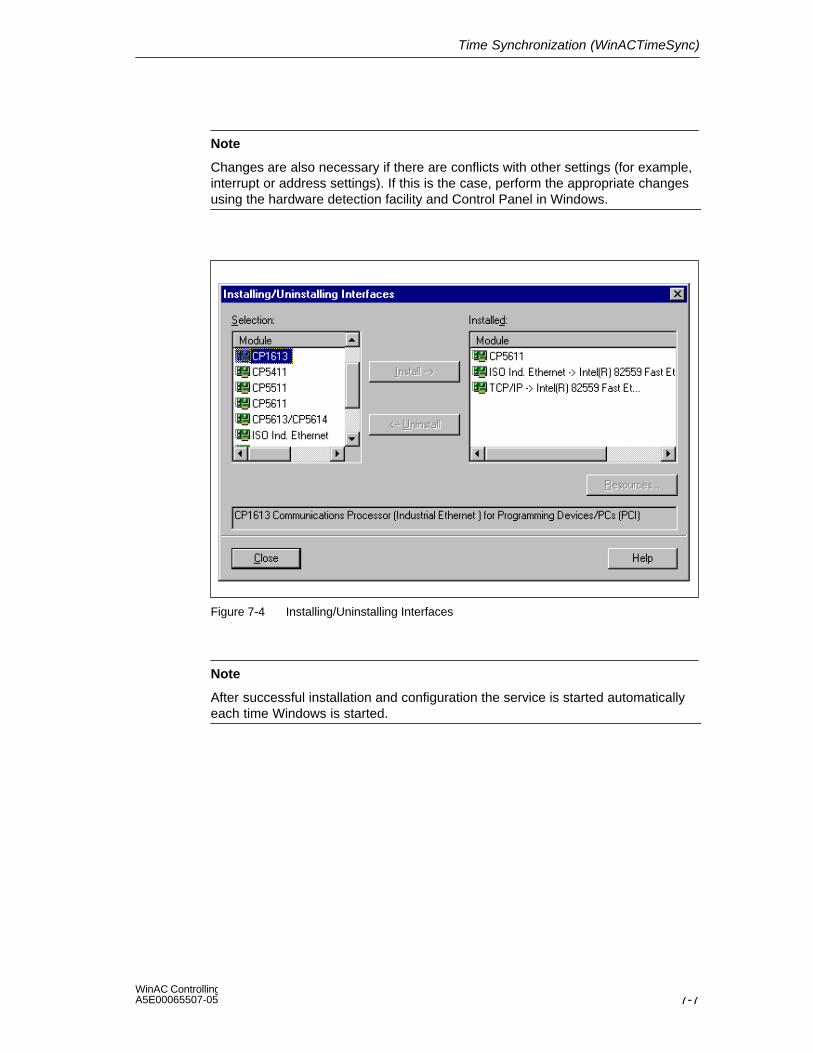
Time Synchronization (WinACTimeSync)
7-7WinAC Controlling with CPU 412-2 PCI/CPU 416-2 PCI Setting Up, CPU Data Version 3.3A5E00065507-05
Note
Changes are also necessary if there are conflicts with other settings (for example,interrupt or address settings). If this is the case, perform the appropriate changesusing the hardware detection facility and Control Panel in Windows.
Figure 7-4 Installing/Uninstalling Interfaces
Note
After successful installation and configuration the service is started automaticallyeach time Windows is started.
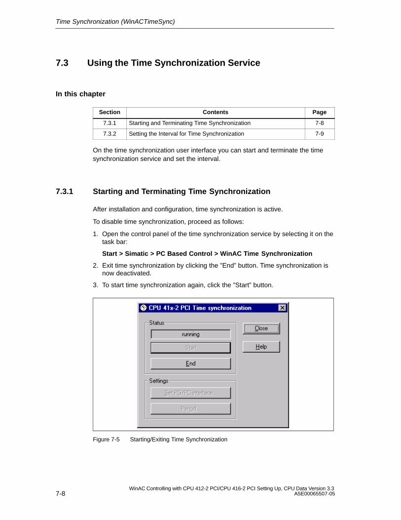
Time Synchronization (WinACTimeSync)
7-8WinAC Controlling with CPU 412-2 PCI/CPU 416-2 PCI Setting Up, CPU Data Version 3.3
A5E00065507-05
7.3 Using the Time Synchronization Service
In this chapter
Section Contents Page
7.3.1 Starting and Terminating Time Synchronization 7-8
7.3.2 Setting the Interval for Time Synchronization 7-9
On the time synchronization user interface you can start and terminate the timesynchronization service and set the interval.
7.3.1 Starting and Terminating Time Synchronization
After installation and configuration, time synchronization is active.
To disable time synchronization, proceed as follows:
1. Open the control panel of the time synchronization service by selecting it on thetask bar:
Start > Simatic > PC Based Control > WinAC Time Synchronization
2. Exit time synchronization by clicking the ”End” button. Time synchronization isnow deactivated.
3. To start time synchronization again, click the ”Start” button.
Figure 7-5 Starting/Exiting Time Synchronization
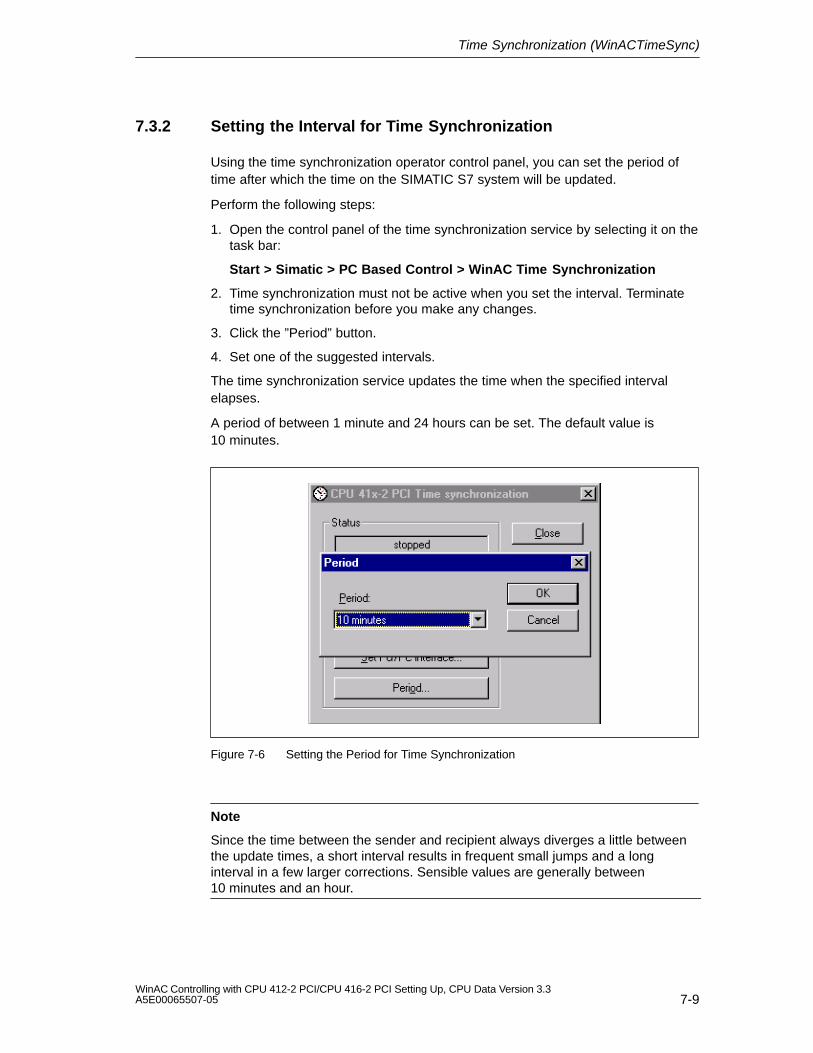
Time Synchronization (WinACTimeSync)
7-9WinAC Controlling with CPU 412-2 PCI/CPU 416-2 PCI Setting Up, CPU Data Version 3.3A5E00065507-05
7.3.2 Setting the Interval for Time Synchronization
Using the time synchronization operator control panel, you can set the period oftime after which the time on the SIMATIC S7 system will be updated.
Perform the following steps:
1. Open the control panel of the time synchronization service by selecting it on thetask bar:
Start > Simatic > PC Based Control > WinAC Time Synchronization
2. Time synchronization must not be active when you set the interval. Terminatetime synchronization before you make any changes.
3. Click the ”Period” button.
4. Set one of the suggested intervals.
The time synchronization service updates the time when the specified intervalelapses.
A period of between 1 minute and 24 hours can be set. The default value is10 minutes.
Figure 7-6 Setting the Period for Time Synchronization
Note
Since the time between the sender and recipient always diverges a little betweenthe update times, a short interval results in frequent small jumps and a longinterval in a few larger corrections. Sensible values are generally between10 minutes and an hour.
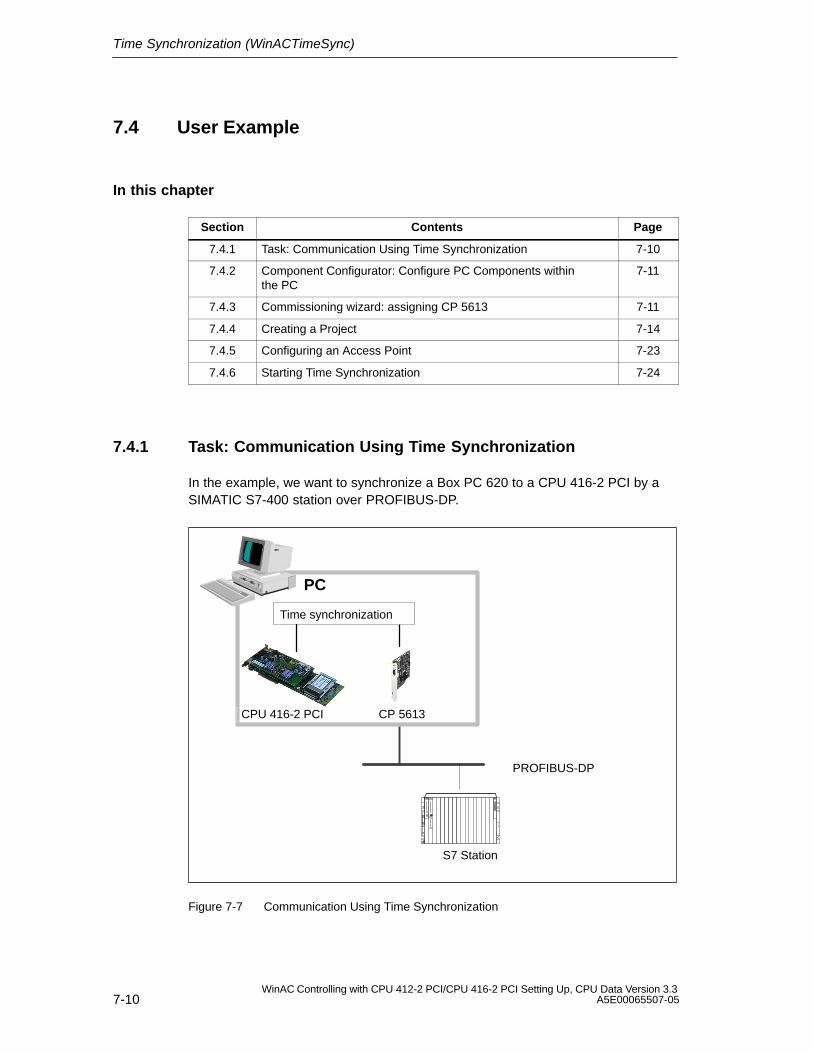
Time Synchronization (WinACTimeSync)
7-10WinAC Controlling with CPU 412-2 PCI/CPU 416-2 PCI Setting Up, CPU Data Version 3.3
A5E00065507-05
7.4 User Example
In this chapter
Section Contents Page
7.4.1 Task: Communication Using Time Synchronization 7-10
7.4.2 Component Configurator: Configure PC Components withinthe PC
7-11
7.4.3 Commissioning wizard: assigning CP 5613 7-11
7.4.4 Creating a Project 7-14
7.4.5 Configuring an Access Point 7-23
7.4.6 Starting Time Synchronization 7-24
7.4.1 Task: Communication Using Time Synchronization
In the example, we want to synchronize a Box PC 620 to a CPU 416-2 PCI by aSIMATIC S7-400 station over PROFIBUS-DP.
Time synchronization
PC
PROFIBUS-DP
S7 Station
CPU 416-2 PCI CP 5613
Figure 7-7 Communication Using Time Synchronization
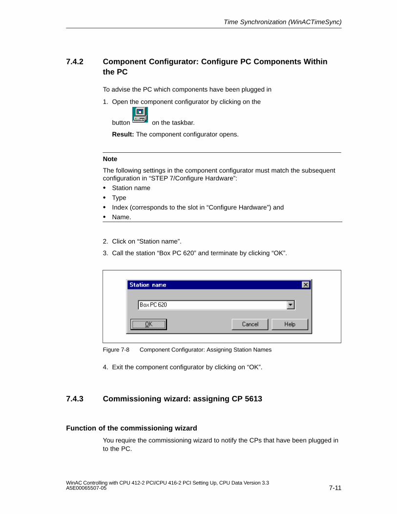
Time Synchronization (WinACTimeSync)
7-11WinAC Controlling with CPU 412-2 PCI/CPU 416-2 PCI Setting Up, CPU Data Version 3.3A5E00065507-05
7.4.2 Component Configurator: Configure PC Components Withinthe PC
To advise the PC which components have been plugged in
1. Open the component configurator by clicking on the
button on the taskbar.
Result: The component configurator opens.
Note
The following settings in the component configurator must match the subsequentconfiguration in “STEP 7/Configure Hardware”:
Station name
Type
Index (corresponds to the slot in “Configure Hardware”) and
Name.
2. Click on “Station name”.
3. Call the station “Box PC 620” and terminate by clicking “OK”.
Figure 7-8 Component Configurator: Assigning Station Names
4. Exit the component configurator by clicking on “OK”.
7.4.3 Commissioning wizard: assigning CP 5613
Function of the commissioning wizard
You require the commissioning wizard to notify the CPs that have been plugged into the PC.
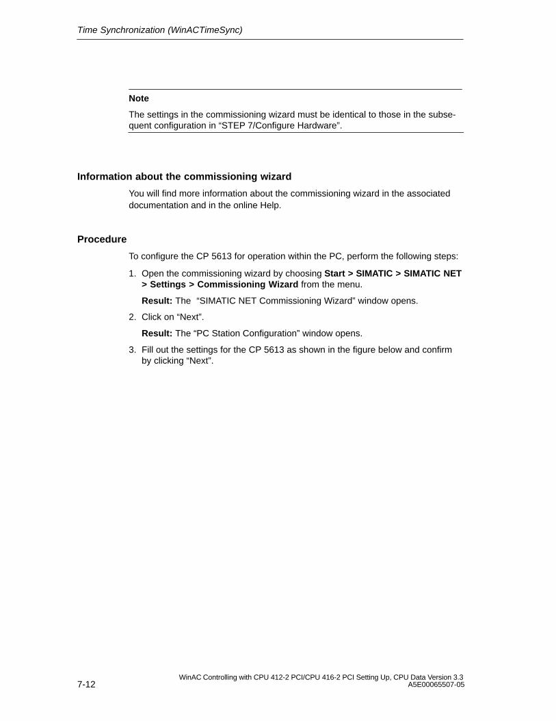
Time Synchronization (WinACTimeSync)
7-12WinAC Controlling with CPU 412-2 PCI/CPU 416-2 PCI Setting Up, CPU Data Version 3.3
A5E00065507-05
Note
The settings in the commissioning wizard must be identical to those in the subse-quent configuration in “STEP 7/Configure Hardware”.
Information about the commissioning wizard
You will find more information about the commissioning wizard in the associateddocumentation and in the online Help.
Procedure
To configure the CP 5613 for operation within the PC, perform the following steps:
1. Open the commissioning wizard by choosing Start > SIMATIC > SIMATIC NET> Settings > Commissioning Wizard from the menu.
Result: The “SIMATIC NET Commissioning Wizard” window opens.
2. Click on “Next”.
Result: The “PC Station Configuration” window opens.
3. Fill out the settings for the CP 5613 as shown in the figure below and confirmby clicking “Next”.
Time Synchronization (WinACTimeSync)
7-13WinAC Controlling with CPU 412-2 PCI/CPU 416-2 PCI Setting Up, CPU Data Version 3.3A5E00065507-05
Note
The settings (index, MAC address, IP address, subnet mask) must be identical tothose in “STEP 7/Configure Hardware”. The index in “STEP 7/Configure Hard-ware” corresponds to the slot.
Figure 7-9 Commissioning wizard: settings for CP 5613
Result: You have then entered all the important settings.
4. Click “Next” or “Finish” as often as is necessary to quit the commissioningwizard.
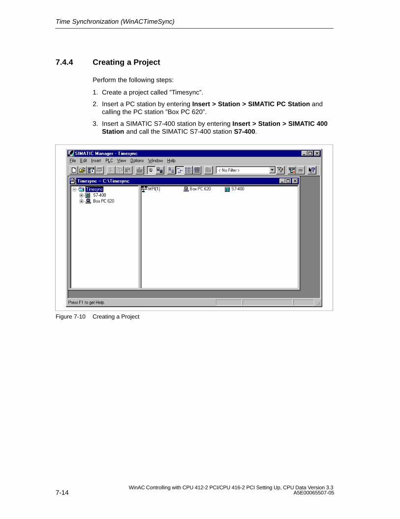
Time Synchronization (WinACTimeSync)
7-14WinAC Controlling with CPU 412-2 PCI/CPU 416-2 PCI Setting Up, CPU Data Version 3.3
A5E00065507-05
7.4.4 Creating a Project
Perform the following steps:
1. Create a project called ”Timesync”.
2. Insert a PC station by entering Insert > Station > SIMATIC PC Station andcalling the PC station ”Box PC 620”.
3. Insert a SIMATIC S7-400 station by entering Insert > Station > SIMATIC 400Station and call the SIMATIC S7-400 station S7-400.
Figure 7-10 Creating a Project
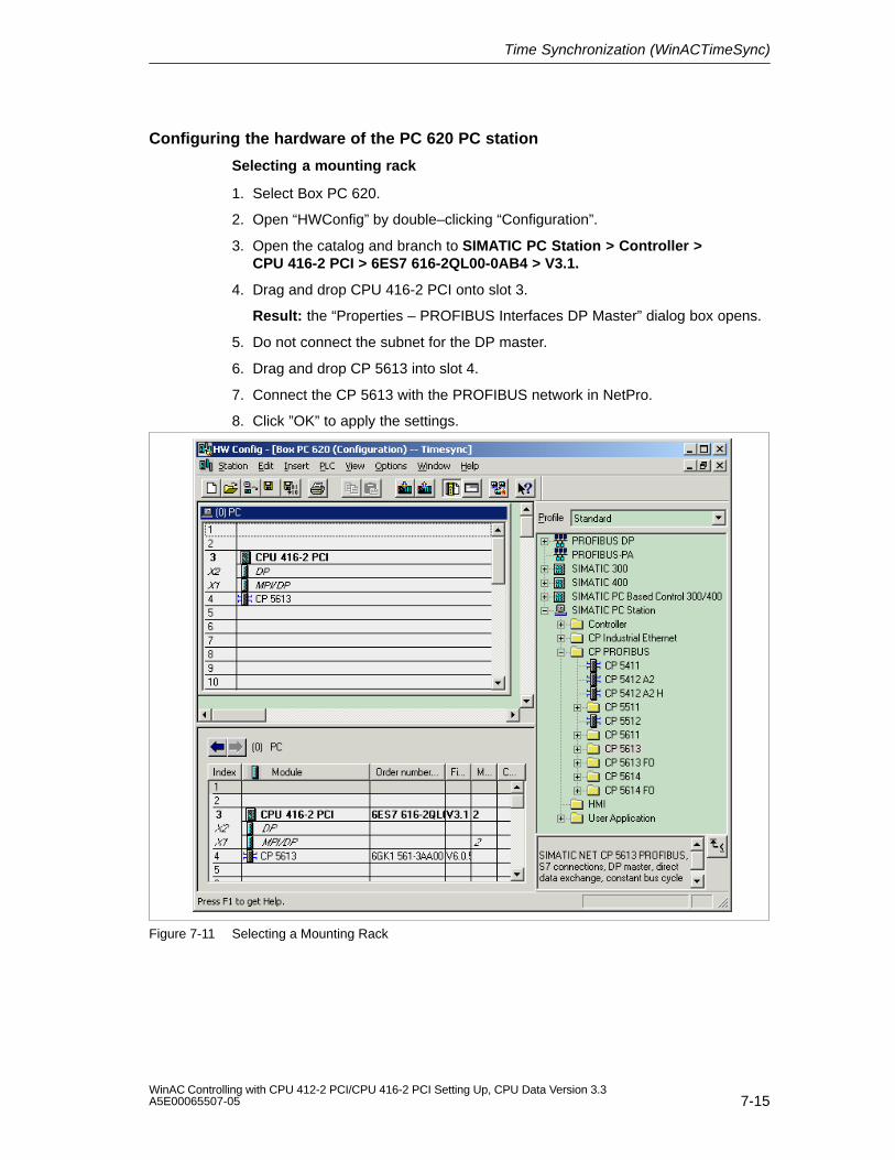
Time Synchronization (WinACTimeSync)
7-15WinAC Controlling with CPU 412-2 PCI/CPU 416-2 PCI Setting Up, CPU Data Version 3.3A5E00065507-05
Configuring the hardware of the PC 620 PC station
Selecting a mounting rack
1. Select Box PC 620.
2. Open “HWConfig” by double–clicking “Configuration”.
3. Open the catalog and branch to SIMATIC PC Station > Controller >CPU 416-2 PCI > 6ES7 616-2QL00-0AB4 > V3.1.
4. Drag and drop CPU 416-2 PCI onto slot 3.
Result: the “Properties – PROFIBUS Interfaces DP Master” dialog box opens.
5. Do not connect the subnet for the DP master.
6. Drag and drop CP 5613 into slot 4.
7. Connect the CP 5613 with the PROFIBUS network in NetPro.
8. Click ”OK” to apply the settings.
Figure 7-11 Selecting a Mounting Rack
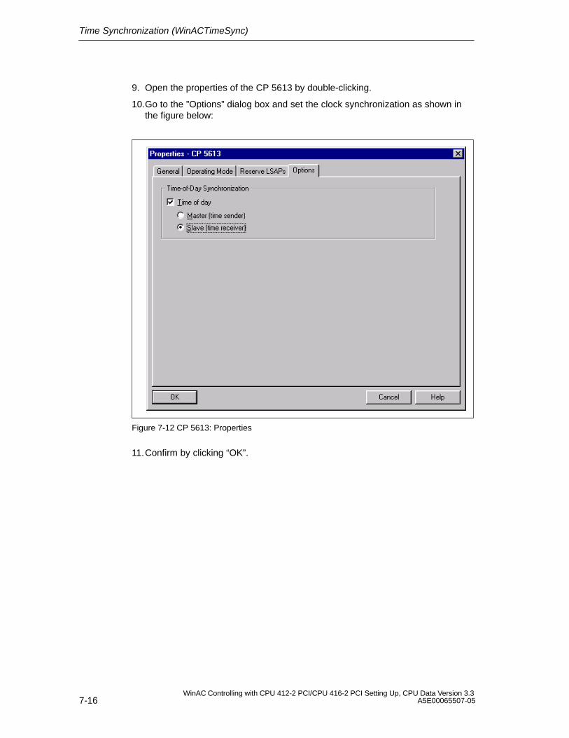
Time Synchronization (WinACTimeSync)
7-16WinAC Controlling with CPU 412-2 PCI/CPU 416-2 PCI Setting Up, CPU Data Version 3.3
A5E00065507-05
9. Open the properties of the CP 5613 by double-clicking.
10.Go to the ”Options” dialog box and set the clock synchronization as shown inthe figure below:
Figure 7-12 CP 5613: Properties
11.Confirm by clicking “OK”.
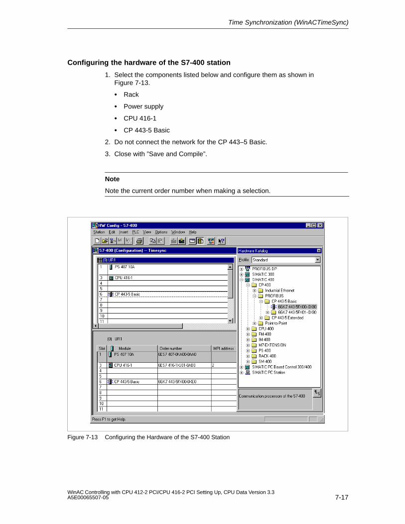
Time Synchronization (WinACTimeSync)
7-17WinAC Controlling with CPU 412-2 PCI/CPU 416-2 PCI Setting Up, CPU Data Version 3.3A5E00065507-05
Configuring the hardware of the S7-400 station
1. Select the components listed below and configure them as shown inFigure 7-13.
Rack
Power supply
CPU 416-1
CP 443-5 Basic
2. Do not connect the network for the CP 443–5 Basic.
3. Close with ”Save and Compile”.
Note
Note the current order number when making a selection.
Figure 7-13 Configuring the Hardware of the S7-400 Station

Time Synchronization (WinACTimeSync)
7-18WinAC Controlling with CPU 412-2 PCI/CPU 416-2 PCI Setting Up, CPU Data Version 3.3
A5E00065507-05
Profibus connection
1. Select the project ”Timesync”.
2. Insert the PROFIBUS subnet by entering Insert > Subnet > PROFIBUS andchanging the name of PROFIBUS to PB-Net.
3. Double–click PB-Net to open it.
4. Double–click the CP 443-5 Basic to select it.
5. Open the properties dialog, and select PB-Net.
6. Assign address “10”.
7. Click ”OK” to apply the settings.
8. Select the DP interface of the Box PC 620 by double-clicking.
9. Open the properties dialog, and select PB-Net.
10.Assign address ”2”.
11.Click ”OK” to apply the settings.
12.Select the CP 5613 with a double–click.
13.Open the properties dialof an select PB-Net.
14.Assign the address “3”.
15.Click ”OK” to apply the settings.
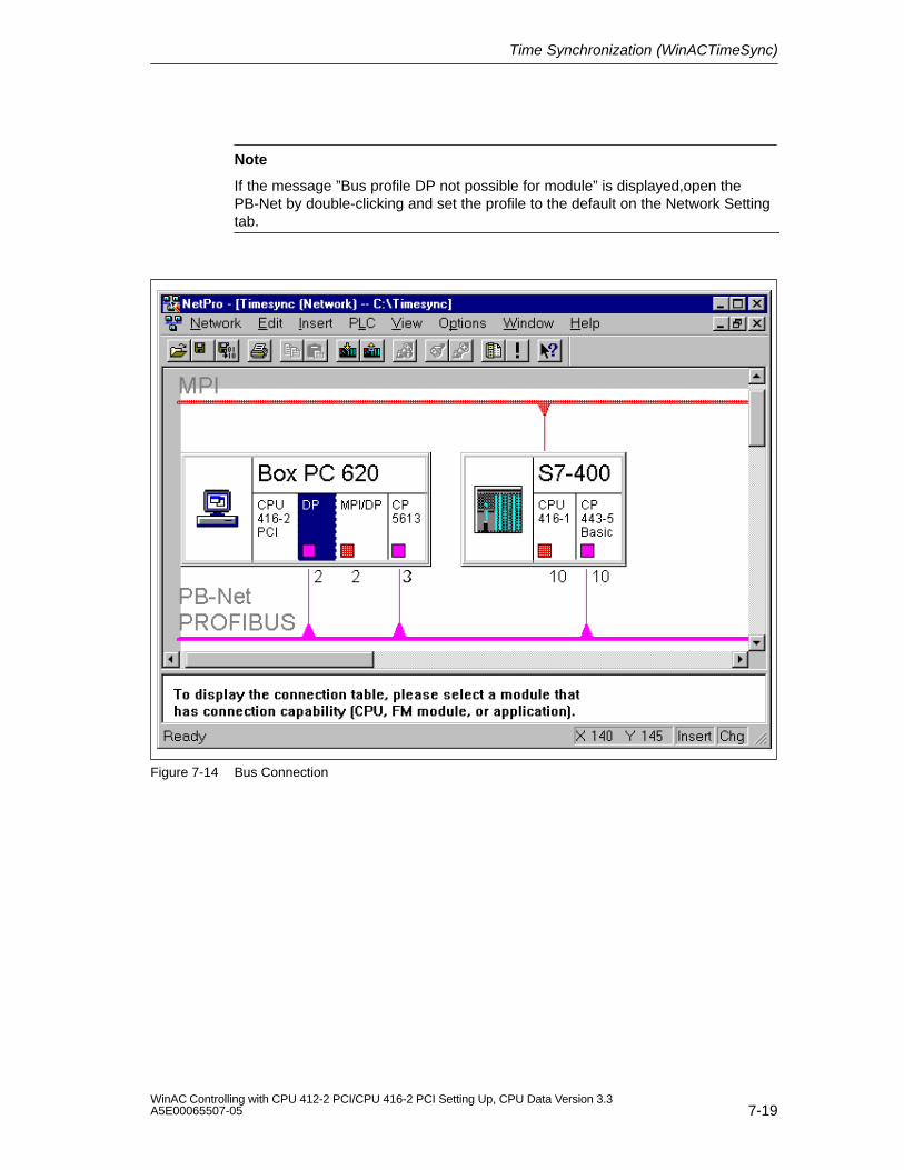
Time Synchronization (WinACTimeSync)
7-19WinAC Controlling with CPU 412-2 PCI/CPU 416-2 PCI Setting Up, CPU Data Version 3.3A5E00065507-05
Note
If the message ”Bus profile DP not possible for module” is displayed,open thePB-Net by double-clicking and set the profile to the default on the Network Settingtab.
Figure 7-14 Bus Connection
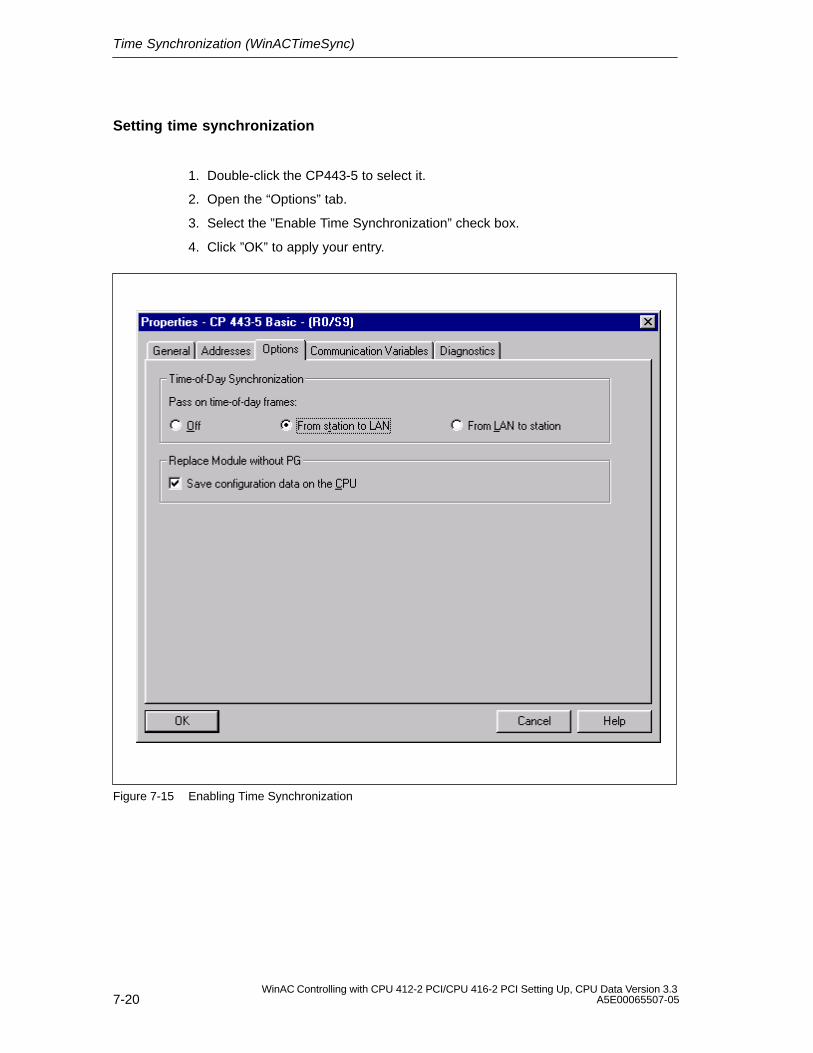
Time Synchronization (WinACTimeSync)
7-20WinAC Controlling with CPU 412-2 PCI/CPU 416-2 PCI Setting Up, CPU Data Version 3.3
A5E00065507-05
Setting time synchronization
1. Double-click the CP443-5 to select it.
2. Open the “Options” tab.
3. Select the ”Enable Time Synchronization” check box.
4. Click ”OK” to apply your entry.
Figure 7-15 Enabling Time Synchronization
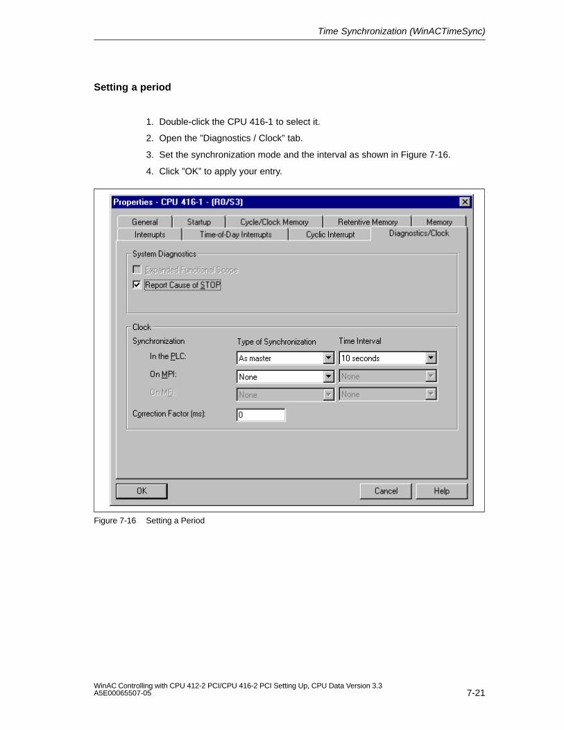
Time Synchronization (WinACTimeSync)
7-21WinAC Controlling with CPU 412-2 PCI/CPU 416-2 PCI Setting Up, CPU Data Version 3.3A5E00065507-05
Setting a period
1. Double-click the CPU 416-1 to select it.
2. Open the ”Diagnostics / Clock” tab.
3. Set the synchronization mode and the interval as shown in Figure 7-16.
4. Click ”OK” to apply your entry.
Figure 7-16 Setting a Period
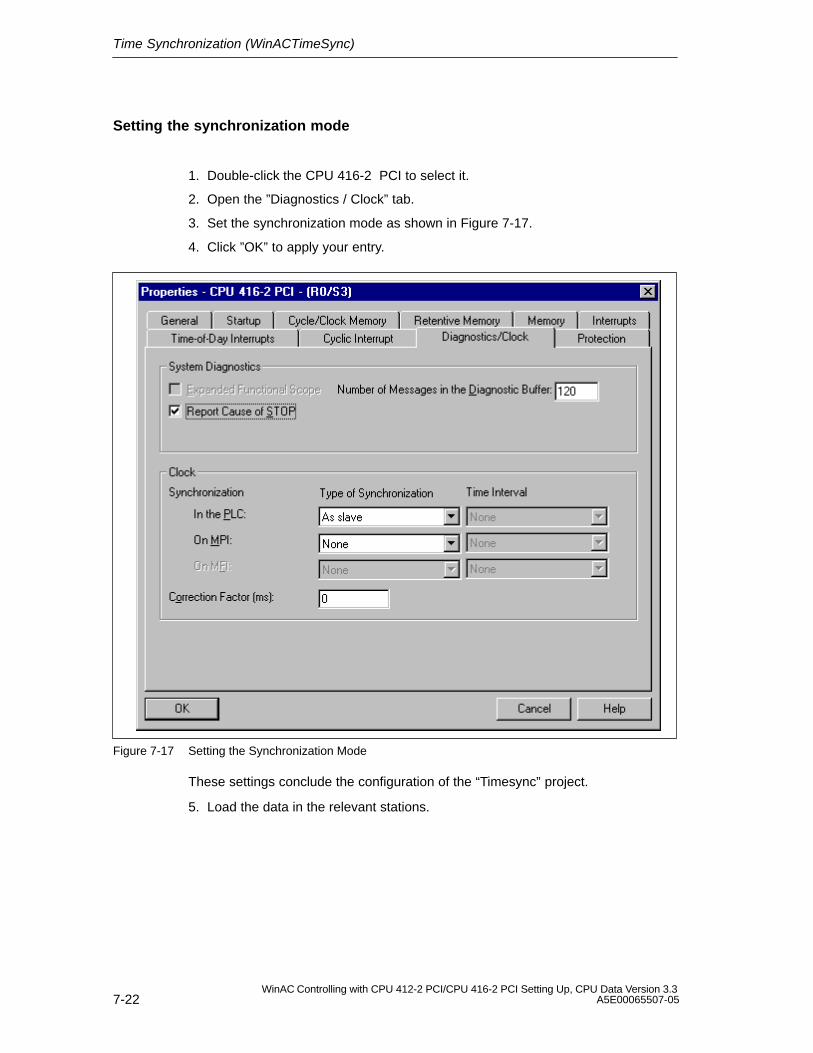
Time Synchronization (WinACTimeSync)
7-22WinAC Controlling with CPU 412-2 PCI/CPU 416-2 PCI Setting Up, CPU Data Version 3.3
A5E00065507-05
Setting the synchronization mode
1. Double-click the CPU 416-2 PCI to select it.
2. Open the ”Diagnostics / Clock” tab.
3. Set the synchronization mode as shown in Figure 7-17.
4. Click ”OK” to apply your entry.
Figure 7-17 Setting the Synchronization Mode
These settings conclude the configuration of the “Timesync” project.
5. Load the data in the relevant stations.
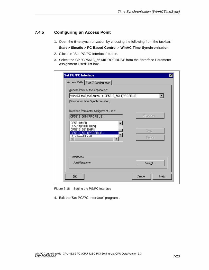
Time Synchronization (WinACTimeSync)
7-23WinAC Controlling with CPU 412-2 PCI/CPU 416-2 PCI Setting Up, CPU Data Version 3.3A5E00065507-05
7.4.5 Configuring an Access Point
1. Open the time synchronization by choosing the following from the taskbar:
Start > Simatic > PC Based Control > WinAC Time Synchronization
2. Click the ”Set PG/PC Interface” button.
3. Select the CP ”CP5613_5614(PROFIBUS)” from the ”Interface ParameterAssignment Used” list box.
Figure 7-18 Setting the PG/PC Interface
4. Exit the“Set PG/PC Interface” program .
Time Synchronization (WinACTimeSync)
7-24WinAC Controlling with CPU 412-2 PCI/CPU 416-2 PCI Setting Up, CPU Data Version 3.3
A5E00065507-05
7.4.6 Starting Time Synchronization
Once you have configured the hardware, set the connections for the project andconfigured the access point, time synchronization can be carried out using thetime-of-day synchronization facility.
1. Open the control panel of the time synchronization service from the task bar:
Start > Simatic > PC Based Control > WinAC Time Synchronization
2. Start time synchronization by clicking “Start”.
8-1WinAC Controlling with CPU 412-2 PCI/CPU 416-2 PCI Setting Up, CPU Data Version 3.3A5E00065507-05
CPU 412-2 PCI and CPU 416-2 PCI –Technical Specifications and Compatibility
In this chapter
Section Contents Page
8.1 Overview of the Parameters for the CPU 41x-2 PCI 8-2
8.2 Performance Features and Technical Specifications of theCPU 412-2 PCI
8-3
8.3 Performance Features and Technical Specifications of theCPU 416-2 PCI
8-7
8.4 Differences of CPU 41x-2 PCI from Previous Version(CPU 41x-2 PCI version 3.1)
8-11
8
CPU 412-2 PCI and CPU 416-2 PCI – Technical Specifications and Compatibility
8-2WinAC Controlling with CPU 412-2 PCI/CPU 416-2 PCI Setting Up, CPU Data Version 3.3
A5E00065507-05
8.1 Overview of the Parameters for the CPU 41x-2 PCI
Introduction
Parameters can be assigned to properties and the response by the CPU. Systemdata blocks incorporate parameter blocks that define the response of the operatingsystem and internal CPU presettings.
Default values
All parameters are set to their default values ex works. With these default values,which are suitable for a whole number of standard applications, the CPU 41x-2 PCIcan be used directly and without additional settings.
Programmable system characteristics
The following list provides an overview of the programmable system characteristicsavailable in the CPU 41x-2 PCI.
General properties
Startup
Cycle/clock memory
Retentive memory
Local data
Interrupts (hardware interrupts, time-delay interrupts, asynchronous errorinterrupts)
Time-of-day interrupts
Watchdog interrupts
Diagnostics/clock
Parameter assignment tool
The different CPU parameters can be set in STEP 7 “Configure Hardware”.
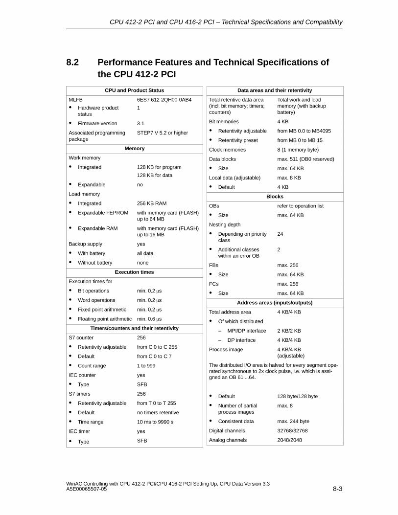
CPU 412-2 PCI and CPU 416-2 PCI – Technical Specifications and Compatibility
8-3WinAC Controlling with CPU 412-2 PCI/CPU 416-2 PCI Setting Up, CPU Data Version 3.3A5E00065507-05
8.2 Performance Features and Technical Specifications ofthe CPU 412-2 PCI
CPU and Product Status
MLFB
Hardware productstatus
6ES7 612-2QH00-0AB4
1
Firmware version 3.1
Associated programmingpackage
STEP7 V 5.2 or higher
Memory
Work memory
Integrated 128 KB for program
128 KB for data
Expandable no
Load memory
Integrated 256 KB RAM
Expandable FEPROM with memory card (FLASH)up to 64 MB
Expandable RAM with memory card (FLASH)up to 16 MB
Backup supply yes
With battery all data
Without battery none
Execution times
Execution times for
Bit operations min. 0.2 s
Word operations min. 0.2 s
Fixed point arithmetic min. 0.2 s
Floating point arithmetic min. 0.6 s
Timers/counters and their retentivity
S7 counter 256
Retentivity adjustable from C 0 to C 255
Default from C 0 to C 7
Count range 1 to 999
IEC counter yes
Type SFB
S7 timers 256
Retentivity adjustable from T 0 to T 255
Default no timers retentive
Time range 10 ms to 9990 s
IEC timer yes
Type SFB
Data areas and their retentivity
Total retentive data area(incl. bit memory; timers;counters)
Total work and loadmemory (with backupbattery)
Bit memories 4 KB
Retentivity adjustable from MB 0.0 to MB4095
Retentivity preset from MB 0 to MB 15
Clock memories 8 (1 memory byte)
Data blocks max. 511 (DB0 reserved)
Size max. 64 KB
Local data (adjustable) max. 8 KB
Default 4 KB
Blocks
OBs refer to operation list
Size max. 64 KB
Nesting depth
Depending on priorityclass
24
Additional classeswithin an error OB
2
FBs max. 256
Size max. 64 KB
FCs max. 256
Size max. 64 KB
Address areas (inputs/outputs)
Total address area 4 KB/4 KB
Of which distributed
– MPI/DP interface 2 KB/2 KB
– DP interface 4 KB/4 KB
Process image 4 KB/4 KB (adjustable)
The distributed I/O area is halved for every segment ope-rated synchronous to 2x clock pulse, i.e. which is assi-gned an OB 61 ...64.
Default 128 byte/128 byte
Number of partialprocess images
max. 8
Consistent data max. 244 byte
Digital channels 32768/32768
Analog channels 2048/2048
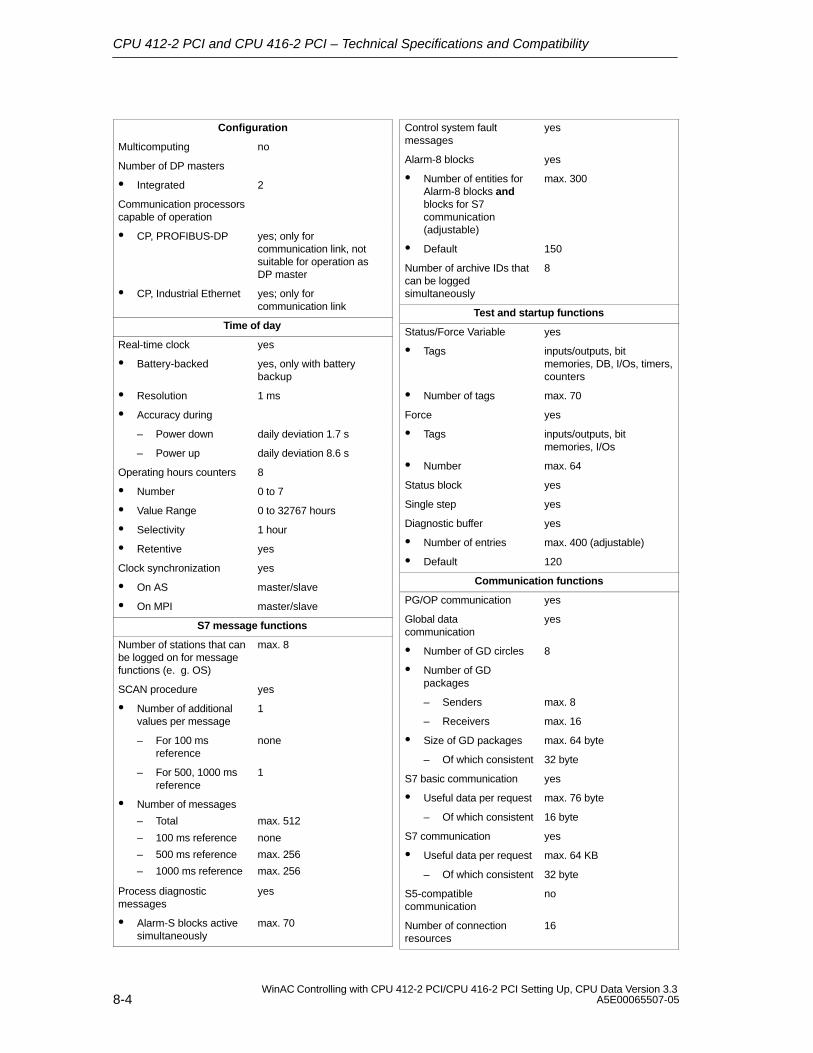
CPU 412-2 PCI and CPU 416-2 PCI – Technical Specifications and Compatibility
8-4WinAC Controlling with CPU 412-2 PCI/CPU 416-2 PCI Setting Up, CPU Data Version 3.3
A5E00065507-05
Configuration
Multicomputing no
Number of DP masters
Integrated 2
Communication processorscapable of operation
CP, PROFIBUS-DP yes; only forcommunication link, notsuitable for operation as DP master
CP, Industrial Ethernet yes; only forcommunication link
Time of day
Real-time clock yes
Battery-backed yes, only with batterybackup
Resolution 1 ms
Accuracy during
– Power down daily deviation 1.7 s
– Power up daily deviation 8.6 s
Operating hours counters 8
Number 0 to 7
Value Range 0 to 32767 hours
Selectivity 1 hour
Retentive yes
Clock synchronization yes
On AS master/slave
On MPI master/slave
S7 message functions
Number of stations that canbe logged on for messagefunctions (e. g. OS)
max. 8
SCAN procedure yes
Number of additionalvalues per message
1
– For 100 msreference
none
– For 500, 1000 msreference
1
Number of messages
– Total
– 100 ms reference
– 500 ms reference
– 1000 ms reference
max. 512
none
max. 256
max. 256
Process diagnosticmessages
yes
Alarm-S blocks activesimultaneously
max. 70
Control system faultmessages
yes
Alarm-8 blocks yes
Number of entities forAlarm-8 blocks andblocks for S7communication(adjustable)
max. 300
Default 150
Number of archive IDs thatcan be loggedsimultaneously
8
Test and startup functions
Status/Force Variable yes
Tags inputs/outputs, bitmemories, DB, I/Os, timers,counters
Number of tags max. 70
Force yes
Tags inputs/outputs, bitmemories, I/Os
Number max. 64
Status block yes
Single step yes
Diagnostic buffer yes
Number of entries max. 400 (adjustable)
Default 120
Communication functions
PG/OP communication yes
Global datacommunication
yes
Number of GD circles 8
Number of GDpackages
– Senders max. 8
– Receivers max. 16
Size of GD packages max. 64 byte
– Of which consistent 32 byte
S7 basic communication yes
Useful data per request max. 76 byte
– Of which consistent 16 byte
S7 communication yes
Useful data per request max. 64 KB
– Of which consistent 32 byte
S5-compatiblecommunication
no
Number of connectionresources
16
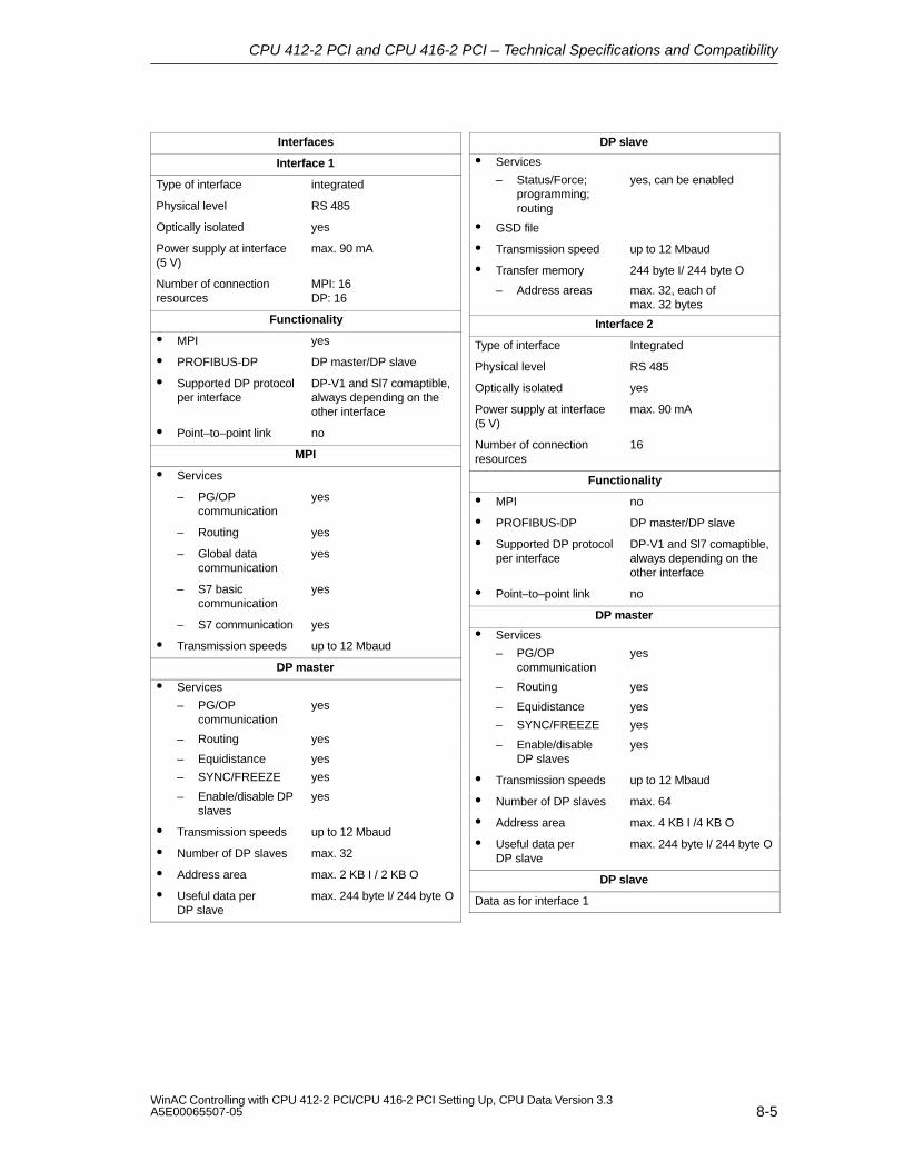
CPU 412-2 PCI and CPU 416-2 PCI – Technical Specifications and Compatibility
8-5WinAC Controlling with CPU 412-2 PCI/CPU 416-2 PCI Setting Up, CPU Data Version 3.3A5E00065507-05
Interfaces
Interface 1
Type of interface integrated
Physical level RS 485
Optically isolated yes
Power supply at interface(5 V)
max. 90 mA
Number of connectionresources
MPI: 16DP: 16
Functionality
MPI yes
PROFIBUS-DP DP master/DP slave
Supported DP protocolper interface
DP-V1 and Sl7 comaptible,always depending on theother interface
Point–to–point link no
MPI
Services
– PG/OPcommunication
yes
– Routing yes
– Global datacommunication
yes
– S7 basiccommunication
yes
– S7 communication yes
Transmission speeds up to 12 Mbaud
DP master
Services
– PG/OPcommunication
yes
– Routing yes
– Equidistance yes
– SYNC/FREEZE yes
– Enable/disable DPslaves
yes
Transmission speeds up to 12 Mbaud
Number of DP slaves max. 32
Address area max. 2 KB I / 2 KB O
Useful data per DP slave
max. 244 byte I/ 244 byte O
DP slave
Services
– Status/Force;programming;routing
yes, can be enabled
GSD file
Transmission speed up to 12 Mbaud
Transfer memory 244 byte I/ 244 byte O
– Address areas max. 32, each of max. 32 bytes
Interface 2
Type of interface Integrated
Physical level RS 485
Optically isolated yes
Power supply at interface(5 V)
max. 90 mA
Number of connectionresources
16
Functionality
MPI no
PROFIBUS-DP DP master/DP slave
Supported DP protocolper interface
DP-V1 and Sl7 comaptible,always depending on theother interface
Point–to–point link no
DP master
Services
– PG/OPcommunication
yes
– Routing yes
– Equidistance yes
– SYNC/FREEZE yes
– Enable/disable DP slaves
yes
Transmission speeds up to 12 Mbaud
Number of DP slaves max. 64
Address area max. 4 KB I /4 KB O
Useful data per DP slave
max. 244 byte I/ 244 byte O
DP slave
Data as for interface 1
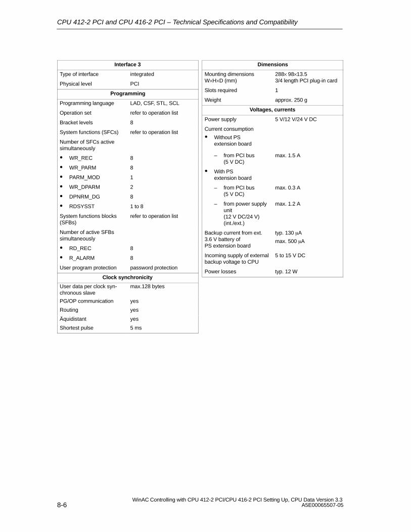
CPU 412-2 PCI and CPU 416-2 PCI – Technical Specifications and Compatibility
8-6WinAC Controlling with CPU 412-2 PCI/CPU 416-2 PCI Setting Up, CPU Data Version 3.3
A5E00065507-05
Interface 3
Type of interface integrated
Physical level PCI
Programming
Programming language LAD, CSF, STL, SCL
Operation set refer to operation list
Bracket levels 8
System functions (SFCs) refer to operation list
Number of SFCs activesimultaneously
WR_REC 8
WR_PARM 8
PARM_MOD 1
WR_DPARM 2
DPNRM_DG 8
RDSYSST 1 to 8
System functions blocks(SFBs)
refer to operation list
Number of active SFBssimultaneously
RD_REC 8
R_ALARM 8
User program protection password protection
Clock synchronicity
User data per clock syn-chronous slave
max.128 bytes
PG/OP communication yes
Routing yes
Äquidistant yes
Shortest pulse 5 ms
Dimensions
Mounting dimensionsW×H×D (mm)
288× 98×13.53/4 length PCI plug-in card
Slots required 1
Weight approx. 250 g
Voltages, currents
Power supply 5 V/12 V/24 V DC
Current consumption
Without PSextension board
– from PCI bus (5 V DC)
max. 1.5 A
With PSextension board
– from PCI bus (5 V DC)
max. 0.3 A
– from power supplyunit (12 V DC/24 V)(int./ext.)
max. 1.2 A
Backup current from ext.3.6 V battery ofPS extension board
typ. 130 A
max. 500 A
Incoming supply of externalbackup voltage to CPU
5 to 15 V DC
Power losses typ. 12 W
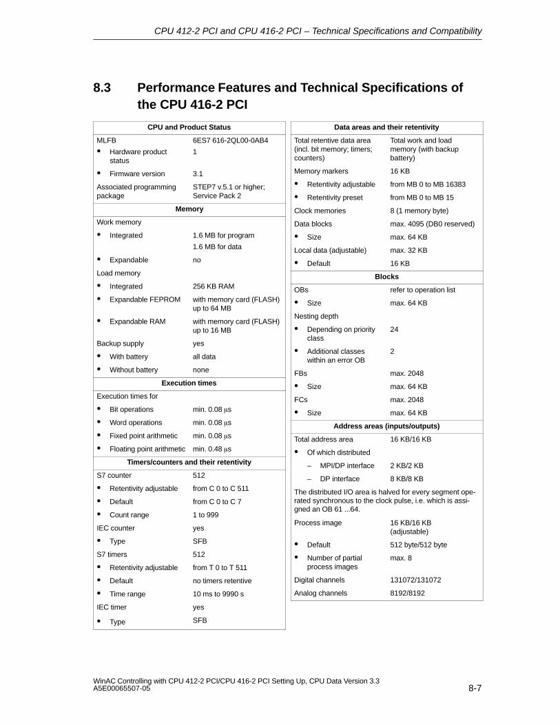
CPU 412-2 PCI and CPU 416-2 PCI – Technical Specifications and Compatibility
8-7WinAC Controlling with CPU 412-2 PCI/CPU 416-2 PCI Setting Up, CPU Data Version 3.3A5E00065507-05
8.3 Performance Features and Technical Specifications ofthe CPU 416-2 PCI
CPU and Product Status
MLFB
Hardware productstatus
6ES7 616-2QL00-0AB4
1
Firmware version 3.1
Associated programmingpackage
STEP7 v.5.1 or higher;Service Pack 2
Memory
Work memory
Integrated 1.6 MB for program
1.6 MB for data
Expandable no
Load memory
Integrated 256 KB RAM
Expandable FEPROM with memory card (FLASH)up to 64 MB
Expandable RAM with memory card (FLASH)up to 16 MB
Backup supply yes
With battery all data
Without battery none
Execution times
Execution times for
Bit operations min. 0.08 s
Word operations min. 0.08 s
Fixed point arithmetic min. 0.08 s
Floating point arithmetic min. 0.48 s
Timers/counters and their retentivity
S7 counter 512
Retentivity adjustable from C 0 to C 511
Default from C 0 to C 7
Count range 1 to 999
IEC counter yes
Type SFB
S7 timers 512
Retentivity adjustable from T 0 to T 511
Default no timers retentive
Time range 10 ms to 9990 s
IEC timer yes
Type SFB
Data areas and their retentivity
Total retentive data area(incl. bit memory; timers;counters)
Total work and loadmemory (with backupbattery)
Memory markers 16 KB
Retentivity adjustable from MB 0 to MB 16383
Retentivity preset from MB 0 to MB 15
Clock memories 8 (1 memory byte)
Data blocks max. 4095 (DB0 reserved)
Size max. 64 KB
Local data (adjustable) max. 32 KB
Default 16 KB
Blocks
OBs refer to operation list
Size max. 64 KB
Nesting depth
Depending on priorityclass
24
Additional classeswithin an error OB
2
FBs max. 2048
Size max. 64 KB
FCs max. 2048
Size max. 64 KB
Address areas (inputs/outputs)
Total address area 16 KB/16 KB
Of which distributed
– MPI/DP interface 2 KB/2 KB
– DP interface 8 KB/8 KB
The distributed I/O area is halved for every segment ope-rated synchronous to the clock pulse, i.e. which is assi-gned an OB 61 ...64.
Process image 16 KB/16 KB (adjustable)
Default 512 byte/512 byte
Number of partialprocess images
max. 8
Digital channels 131072/131072
Analog channels 8192/8192
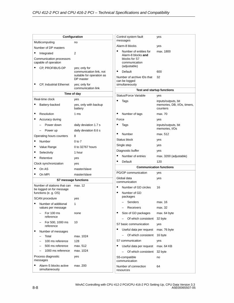
CPU 412-2 PCI and CPU 416-2 PCI – Technical Specifications and Compatibility
8-8WinAC Controlling with CPU 412-2 PCI/CPU 416-2 PCI Setting Up, CPU Data Version 3.3
A5E00065507-05
Configuration
Multicomputing no
Number of DP masters
Integrated 2
Communication processorscapable of operation
CP, PROFIBUS-DP yes; only forcommunication link, notsuitable for operation as DP master
CP, Industrial Ethernet yes; only forcommunication link
Time of day
Real-time clock yes
Battery-backed yes, only with backupbattery
Resolution 1 ms
Accuracy during
– Power down daily deviation 1.7 s
– Power up daily deviation 8.6 s
Operating hours counters 8
Number 0 to 7
Value Range 0 to 32767 hours
Selectivity 1 hour
Retentive yes
Clock synchronization yes
On AS master/slave
On MPI master/slave
S7 message functions
Number of stations that canbe logged on for messagefunctions (e. g. OS)
max. 12
SCAN procedure yes
Number of additionalvalues per message
1
– For 100 msreference
none
– For 500, 1000 msreference
10
Number of messages
– Total
– 100 ms reference
– 500 ms reference
– 1000 ms reference
max. 1024
128
max. 512
max. 1024
Process diagnosticmessages
yes
Alarm-S blocks activesimultaneously
max. 200
Control system faultmessages
yes
Alarm-8 blocks yes
Number of entities forAlarm-8 blocks andblocks for S7communication(adjustable)
max. 1800
Default 600
Number of archive IDs thatcan be loggedsimultaneously
32
Test and startup functions
Status/Force Variable yes
Tags inputs/outputs, bitmemories, DB, I/Os, timers,counters
Number of tags max. 70
Force yes
Tags inputs/outputs, bitmemories, I/Os
Number max. 512
Status block yes
Single step yes
Diagnostic buffer yes
Number of entries max. 3200 (adjustable)
Default 120
Communication functions
PG/OP communication yes
Global datacommunication
yes
Number of GD circles 16
Number of GDpackages
– Senders max. 16
– Receivers max. 32
Size of GD packages max. 64 byte
– Of which consistent 32 byte
S7 basic communication yes
Useful data per request max. 76 byte
– Of which consistent 16 byte
S7 communication yes
Useful data per request max. 64 KB
– Of which consistent 32 byte
S5-compatiblecommunication
no
Number of connectionresources
64

CPU 412-2 PCI and CPU 416-2 PCI – Technical Specifications and Compatibility
8-9WinAC Controlling with CPU 412-2 PCI/CPU 416-2 PCI Setting Up, CPU Data Version 3.3A5E00065507-05
Interfaces
Interface 1
Type of interface integrated
Physical level RS 485
Optically isolated yes
Power supply at interface(5 V)
max. 90 mA
Number of connectionresources
MPI: 44DP: 32
Functionality
MPI yes
PROFIBUS-DP DP master/DP slave
Supported DP protocolper interface
DP-V1 and Sl7 comaptible,always depending on theother interface
Point-to-point link no
MPI
Services
– PG/OPcommunication
yes
– Routing yes
– Global datacommunication
yes
– S7 basiccommunication
yes
– S7 communication yes
Transmission speeds up to 12 Mbaud
DP master
Services
– PG/OPcommunication
yes
– Routing yes
– Equidistance yes
– SYNC/FREEZE yes
– Enable/disable DPslaves
yes
Transmission speeds up to 12 Mbaud
Number of DP slaves max. 32
Address area max. 2 KB I / 2 KB O
Useful data per DPslave
max. 244 byte I/ 244 byte O
DP slave
Services
– Status/Force;programming;routing
yes, can be enabled
GSD file
Transmission speed up to 12 Mbaud
Transfer memory 244 byte I/ 244 byte O
– Address areas max. 32, each of max. 32 bytes
Interface 2
Type of interface integrated
Physical level RS 485
Optically isolated yes
Power supply at interface(5 V)
max. 90 mA
Number of connectionresources
32
Functionality
MPI no
PROFIBUS-DP DP master/DP slave
Supported DP protocolper interface
DP-V1 and Sl7 comaptible,always depending on theother interface
Point–to–point link no
DP master
Services
– PG/OPcommunication
yes
– – Routing yes
– Equidistance yes
– SYNC/FREEZE yes
– Enable/disable DPslaves
yes
Transmission speeds up to 12 Mbaud
Number of DP slaves max. 125
Address area max. 8 KB I /8 KB O
Useful data per DPslave
max. 244 byte I/ 244 byte O
DP slave
Data as for interface 1
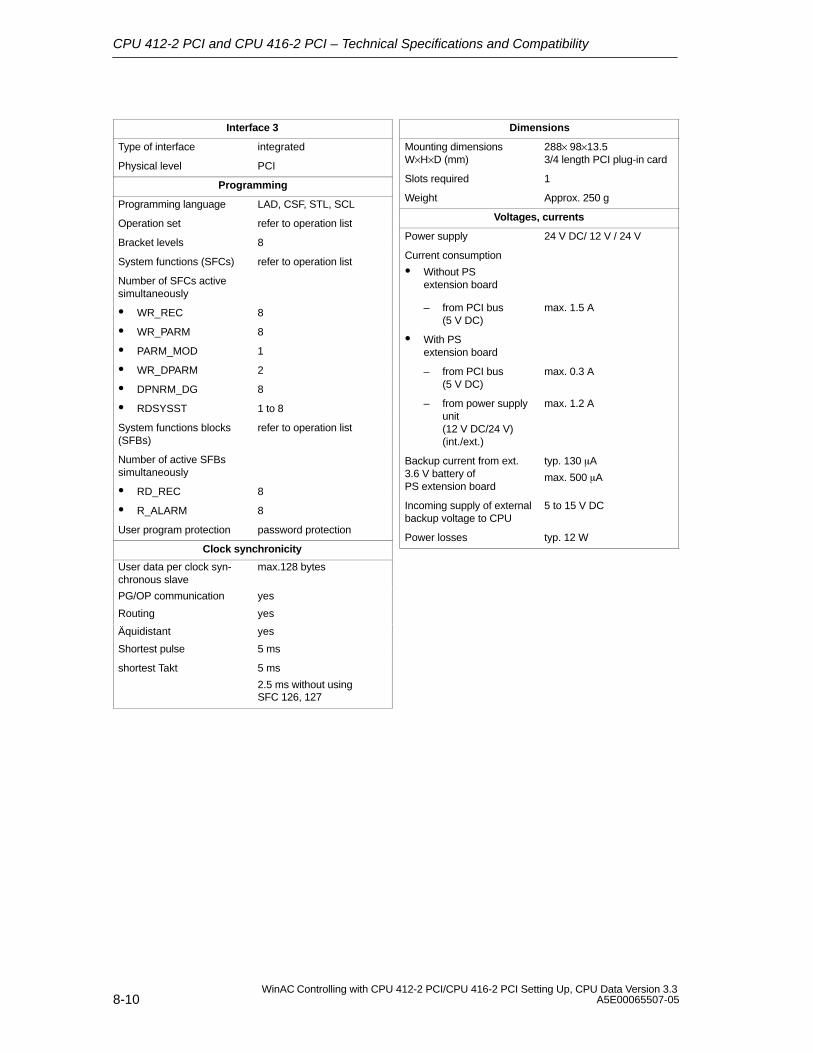
CPU 412-2 PCI and CPU 416-2 PCI – Technical Specifications and Compatibility
8-10WinAC Controlling with CPU 412-2 PCI/CPU 416-2 PCI Setting Up, CPU Data Version 3.3
A5E00065507-05
Interface 3
Type of interface integrated
Physical level PCI
Programming
Programming language LAD, CSF, STL, SCL
Operation set refer to operation list
Bracket levels 8
System functions (SFCs) refer to operation list
Number of SFCs activesimultaneously
WR_REC 8
WR_PARM 8
PARM_MOD 1
WR_DPARM 2
DPNRM_DG 8
RDSYSST 1 to 8
System functions blocks(SFBs)
refer to operation list
Number of active SFBssimultaneously
RD_REC 8
R_ALARM 8
User program protection password protection
Clock synchronicity
User data per clock syn-chronous slave
max.128 bytes
PG/OP communication yes
Routing yes
Äquidistant yes
Shortest pulse 5 ms
shortest Takt 5 ms
2.5 ms without using SFC 126, 127
Dimensions
Mounting dimensionsW×H×D (mm)
288× 98×13.53/4 length PCI plug-in card
Slots required 1
Weight Approx. 250 g
Voltages, currents
Power supply 24 V DC/ 12 V / 24 V
Current consumption
Without PSextension board
– from PCI bus (5 V DC)
max. 1.5 A
With PSextension board
– from PCI bus (5 V DC)
max. 0.3 A
– from power supplyunit (12 V DC/24 V)(int./ext.)
max. 1.2 A
Backup current from ext.3.6 V battery ofPS extension board
typ. 130 A
max. 500 A
Incoming supply of externalbackup voltage to CPU
5 to 15 V DC
Power losses typ. 12 W
CPU 412-2 PCI and CPU 416-2 PCI – Technical Specifications and Compatibility
8-11WinAC Controlling with CPU 412-2 PCI/CPU 416-2 PCI Setting Up, CPU Data Version 3.3A5E00065507-05
8.4 Differences of CPU 41x-2 PCI from Previous Version(CPU 41x-2 PCI Version 3.2)
You will find a list of changes compared to CPU 41x-2 PCI V3.2 in the following:
You can also operate CPU 41x-2 PCI under Windows XP Professional with SP1or later
Windows NT SP 4 is no longer supported.
Using SFC 126 “SYNC_PI” and SFC 127 “SYNC_PO” you can update processimage partitions synchronous to the DP clock.
Using SFC 103 “DP_TOPOL” you can determine the bus topology of a DP master system by triggering the diagnostics repeater.
Reserved address area for a technological application
!Caution
In version 3.2 or higher: in the CPU 412-2 PCI, the PEW 4096 to 8190 and PAW4096 to 8190 – in the CPU 416-2 PCI the PEW 16384 to 20478 and PAW 16384to 20478 – are reserved for a technological application.
If you access the above address area in your STEP 7 user program, an I/O access error is not generated, irrespective of whether or not a technologicalfunction is being operated in this area.
Changing from CPU 41x-2 PCI to CPU 41x-2 PCI version 3.3
You can use all the STEP 7 user programs (version 4.01 or higher) you wrote forthe CPU PCI version 3.2 in conjunction with version 3.3. That means STEP 7 userprograms for
CPU 412-2 PCI/ version 3.2 run on the CPU 412-2 PCI version 3.3 and on theCPU 416–2 PCI version 3.3,
and
CPU 416-2 PCI version 3.1 on the CPU 416-2 PCI version 3.2
You can also use memory cards with STEP 7 user programs for CPUs 41x-2 PCI.
The following applies here again:
Memory cards of the CPU 412-2 PCI version 3.2 run on the CPU 412-2 PCIversion 3.3 and on the CPU 416-2 PCI version 3.3.
and
Memory cards of the CPU 416-2 PCI version 3.2 run on the CPU 416-2 PCIversion 3.3.
CPU 412-2 PCI and CPU 416-2 PCI – Technical Specifications and Compatibility
8-12WinAC Controlling with CPU 412-2 PCI/CPU 416-2 PCI Setting Up, CPU Data Version 3.3
A5E00065507-05
Uploading a FLASH Card from CPU to STEP 7/Configure Hardware
You can upload a STEP 7 user program by inserting a FLASH card from an oldCPU 41x-2 PCI version 3.2 into a new CPU 41x-2 PCI version 3.3.
Downloading a configuration to a RAM card with STEP 7/Configure Hardware
You can download a STEP 7 user program that you wrote for a CPU 41x-2 PCIversion 3.2 onto a new CPU 41x-2 PCI version 3.3.

9-1WinAC Controlling with CPU 412-2 PCI/CPU 416-2 PCI Setting Up, CPU Data Version 3.3A5E00065507-05
PS Extension Board
Order No.
6ES7 678-1RA00-0XB0
The PS extension board can be ordered separately.
Function
The PS extension board (PS: power supply) is used to supply voltage to theCPU 41x-2 PCI independently of the PC power supply unit. In this way it ispossible to operate the CPU 41x-2 PCI even when the PC has been powereddown.
By connecting the backup battery, warm restart (restart) and complete restart arepossible for the CPU 41x-2 PCI.
In addition, you operate the fan on the PC with the PS extension board.
The PS extension board (PS: power supply) provides the CPU 41x-2 PCI on thePC with the following voltages:
5 V DC for supplying the CPU 41x-2 PCI
12 V DC for supplying the fan on the PC
Battery voltage for backup supply
You will find further information on installing and connecting thePS extension board in Chapter 2.
9
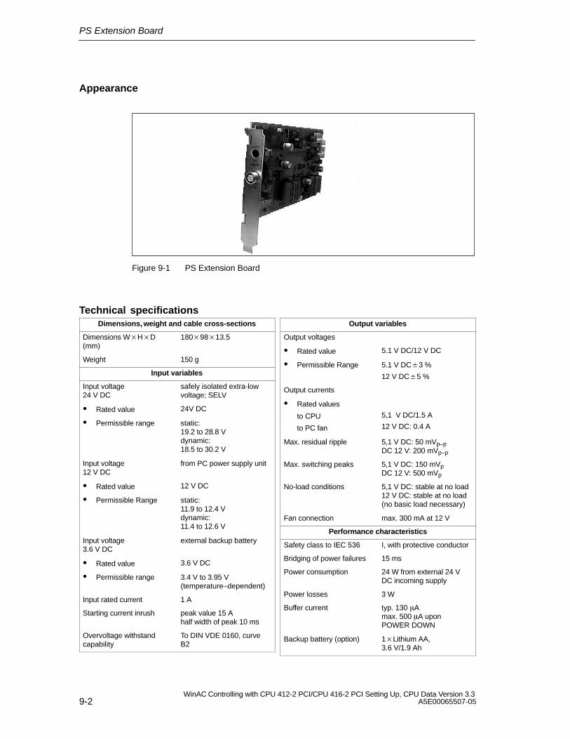
PS Extension Board
9-2WinAC Controlling with CPU 412-2 PCI/CPU 416-2 PCI Setting Up, CPU Data Version 3.3
A5E00065507-05
Appearance
Figure 9-1 PS Extension Board
Technical specificationsDimensions, weight and cable cross-sections
Dimensions WHD(mm)
1809813.5
Weight 150 g
Input variables
Input voltage 24 V DC
safely isolated extra-lowvoltage; SELV
Rated value 24V DC
Permissible range static:19.2 to 28.8 Vdynamic:18.5 to 30.2 V
Input voltage 12 V DC
from PC power supply unit
Rated value 12 V DC
Permissible Range static:11.9 to 12.4 Vdynamic:11.4 to 12.6 V
Input voltage 3.6 V DC
external backup battery
Rated value 3.6 V DC
Permissible range 3.4 V to 3.95 V (temperature–dependent)
Input rated current 1 A
Starting current inrush peak value 15 Ahalf width of peak 10 ms
Overvoltage withstandcapability
To DIN VDE 0160, curveB2
Output variables
Output voltages
Rated value 5.1 V DC/12 V DC
Permissible Range 5.1 V DC3 %
12 V DC5 %
Output currents
Rated values
to CPU
to PC fan
5,1 V DC/1.5 A
12 V DC: 0.4 A
Max. residual ripple 5,1 V DC: 50 mVp–pDC 12 V: 200 mVp–p
Max. switching peaks 5,1 V DC: 150 mVpDC 12 V: 500 mVp
No-load conditions 5,1 V DC: stable at no load12 V DC: stable at no load(no basic load necessary)
Fan connection max. 300 mA at 12 V
Performance characteristics
Safety class to IEC 536 I, with protective conductor
Bridging of power failures 15 ms
Power consumption 24 W from external 24 VDC incoming supply
Power losses 3 W
Buffer current typ. 130 A max. 500 A upon POWER DOWN
Backup battery (option) 1Lithium AA,3.6 V/1.9 Ah
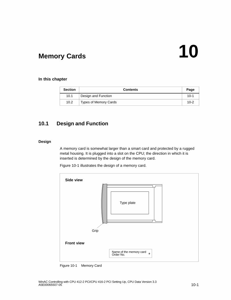
10-1WinAC Controlling with CPU 412-2 PCI/CPU 416-2 PCI Setting Up, CPU Data Version 3.3A5E00065507-05
Memory Cards
In this chapter
Section Contents Page
10.1 Design and Function 10-1
10.2 Types of Memory Cards 10-2
10.1 Design and Function
Design
A memory card is somewhat larger than a smart card and protected by a ruggedmetal housing. It is plugged into a slot on the CPU; the direction in which it isinserted is determined by the design of the memory card.
Figure 10-1 illustrates the design of a memory card.
Grip
Side view
Type plate
Front view
Name of the memory cardOrder No.
Figure 10-1 Memory Card
10

Memory Cards
10-2WinAC Controlling with CPU 412-2 PCI/CPU 416-2 PCI Setting Up, CPU Data Version 3.3
A5E00065507-05
Function
The memory card and an integrated memory area on the CPU motherboardtogether form the load memory of the CPU. During operation, the load memory cancontain the entire user program, including the comments, symbols and specificadditional information that allows uncompiling of the user program, and all moduleparameters.
In order to make full use of the CPU memory, you should insert a memory cardhaving a capacity higher than that of the CPU work memory.
What is stored on the memory card?
You can store the following data on the memory card:
user program – in other words, blocks (OBs, FBs, FCs, DBs)
parameters determining the response of the CPU
parameters determining the response of the I/O modules
10.2 Types of Memory Cards
You can insert two types of memory cards:
RAM card or
FLASH card (FEPROM card)
!Caution
Memory cards that are not compatible with the system must not be inserted in theCPU 41x-2 PCI.
What type of memory card should you use?
Whether you use a RAM card or a FLASH card depends on how you want to usethe memory card.
If ... Then ...
You store the data in RAM and want tochange your program even during RUN-Pmode.
Use a RAM card
You want to save you user programpermanently even in a de-energized state(without battery backup or external to theCPU).
Use a FLASH card
Memory Cards
10-3WinAC Controlling with CPU 412-2 PCI/CPU 416-2 PCI Setting Up, CPU Data Version 3.3A5E00065507-05
Table 10-1 Differences Between RAM Card and FLASH Card
RAM Card FLASH Card
The RAM card must be plugged into the CPU toload the user program. The user program is loadedwith the help of the programming device (PG).
There are two ways n which you can load the userprogram:
You set the CPU to STOP with the modeswitch, plug the FLASH card into the CPU andload the user program into the load memorywith the assistance of the programming device(PG).
You load the user program in Offline mode onthe programming device into the FLASH cardand then plug the FLASH card into the CPU.
You can load the complete user program orindividual parts, such as FBs, FCs, OBs, DBs orSDBs, into the load memory in STOP or RUN-Pmode.
You can reload your complete user program. Youcan reload smallish program sections with the PGinto the load memory integrated on the CPU. Withlargish program changes, you must always reloadthe FLASH card with the complete user program.
If you remove the RAM card from the CPU, theinformation stored on it will be lost. In addition, theCPU prompts you to perform a memory reset. TheRAM card goes not have an integrated backupbattery.
If an external backup voltage is fed into the “BATT.”socket on the PS extension board, the memorycontents of the RAM card are retained after the PChas been turned off or as long as the RAM card isplugged into the CPU.
The FLASH card does not need voltage to store itscontents – in other words, the information itcontains is retained if you remove the FLASH cardfrom the CPU or operate your system without abackup battery (without external backup voltage atthe ”BATT.” socket of the PS extension board).
What memory card capacity should you use?
The capacity of the memory card you use depends on the scope of the userprogram and the additional memory requirement resulting from the use of functionmodules and communication processors. You can estimate their memoryrequirements in STEP 7.
Memory Cards
10-4WinAC Controlling with CPU 412-2 PCI/CPU 416-2 PCI Setting Up, CPU Data Version 3.3
A5E00065507-05
Changing a memory card
!Warning
The memory card can only be removed and plugged in when the PC is open. Youcan also change the memory card while the CPU 41x-2 PCI is operating.
Replacement of the memory card while the CPU 41x-2 PCI is operating is allowedonly when the manufacturer of the PC authorizes the PC to be opened while thePC is energized.
Make sure you do not touch any live parts when a PC is open!
You can replace the memory card in a de-energized state or while the CPU41x-2 PCI is operating.
To change the memory card, perform the following steps:
1. Click the STOP option button.
2. Extract the inserted memory card.
3. Plug the memory card into the slot on the CPU and push the memory cardhome into the slot – in other words, as far as the stop.
Result: the CPU prompts you to perform a memory reset by the STOPindication flashing slowly at 0.5 Hz.
4. Click the MRES option button.
Result: the STOP indication flashes for at least 3 seconds at 2 Hz (a memoryreset is performed) and then changes to being permanently on.
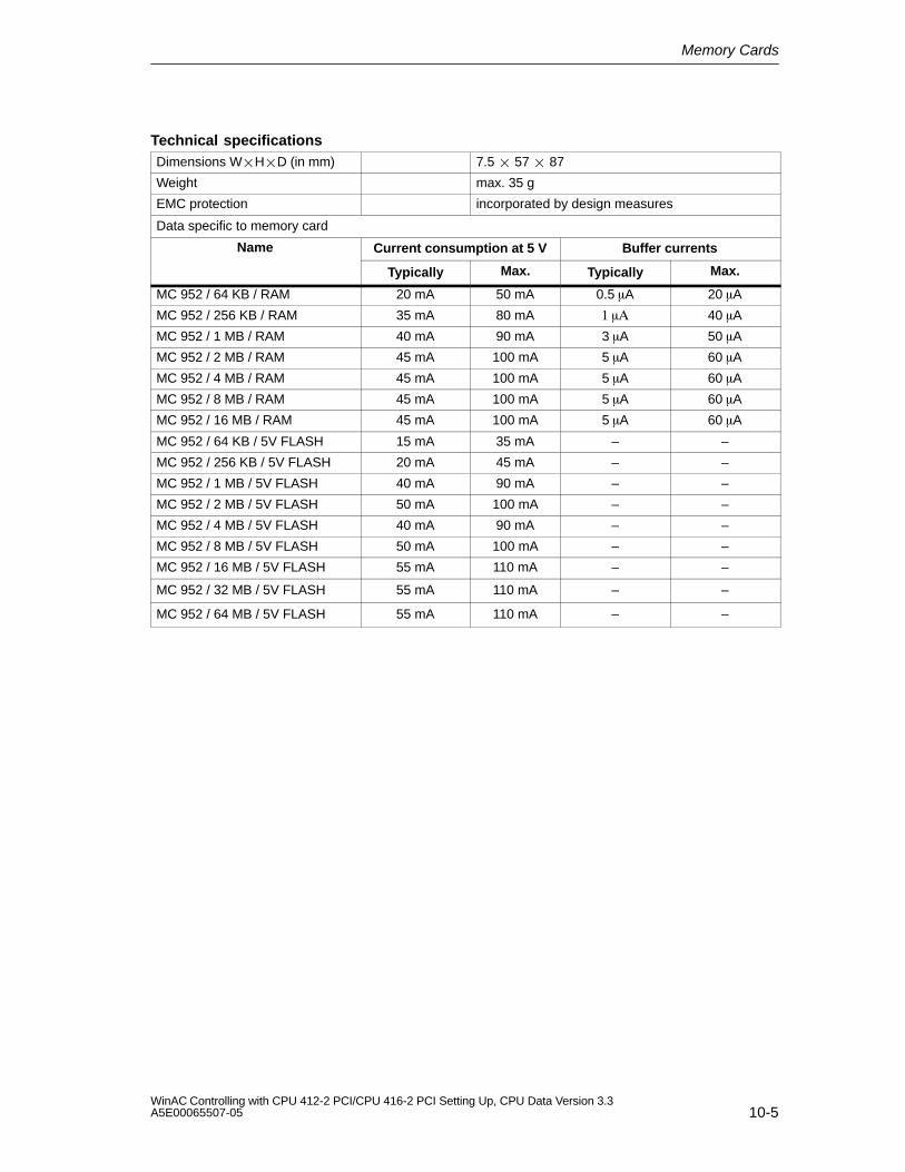
Memory Cards
10-5WinAC Controlling with CPU 412-2 PCI/CPU 416-2 PCI Setting Up, CPU Data Version 3.3A5E00065507-05
Technical specificationsDimensions WHD (in mm) 7.5 57 87
Weight max. 35 g
EMC protection incorporated by design measures
Data specific to memory card
Name Current consumption at 5 V Buffer currents
Typically Max. Typically Max.
MC 952 / 64 KB / RAM 20 mA 50 mA 0.5 A 20 A
MC 952 / 256 KB / RAM 35 mA 80 mA 40 A
MC 952 / 1 MB / RAM 40 mA 90 mA 3 A 50 A
MC 952 / 2 MB / RAM 45 mA 100 mA 5 A 60 A
MC 952 / 4 MB / RAM 45 mA 100 mA 5 A 60 A
MC 952 / 8 MB / RAM 45 mA 100 mA 5 A 60 A
MC 952 / 16 MB / RAM 45 mA 100 mA 5 A 60 A
MC 952 / 64 KB / 5V FLASH 15 mA 35 mA – –
MC 952 / 256 KB / 5V FLASH 20 mA 45 mA – –
MC 952 / 1 MB / 5V FLASH 40 mA 90 mA – –
MC 952 / 2 MB / 5V FLASH 50 mA 100 mA – –
MC 952 / 4 MB / 5V FLASH 40 mA 90 mA – –
MC 952 / 8 MB / 5V FLASH 50 mA 100 mA – –
MC 952 / 16 MB / 5V FLASH 55 mA 110 mA – –
MC 952 / 32 MB / 5V FLASH 55 mA 110 mA – –
MC 952 / 64 MB / 5V FLASH 55 mA 110 mA – –

Memory Cards
10-6WinAC Controlling with CPU 412-2 PCI/CPU 416-2 PCI Setting Up, CPU Data Version 3.3
A5E00065507-05
A-1WinAC Controlling with CPU 412-2 PCI/CPU 416-2 PCI Setting Up, CPU Data Version 3.3A5E00065507-05
General Technical Specifications
What are general technical specifications?
The general technical specifications contain the standards and test values withwhich the CPU 41x-2 PCI and the PS extension board comply and meet, as wellas the test criteria to which the modules were tested.
In this chapter
This appendix contains the following topics concerning general technicalspecifications:
Section Contents Page
A.1 Standards, Certificates and Approvals A-1
A.2 Electromagnetic Compatibility A-3
A.3 Shipping and Storage Conditions A-4
A.4 Mechanical and Climatic Environmental Conditions A-6
A.5 Certification for USA, Canada and Australia A-8
A.1 Standards, Certificates and Approvals
Introduction
This section contains details of
the most important standards with whose criteria the modules comply, and
approvals for the modules.
A
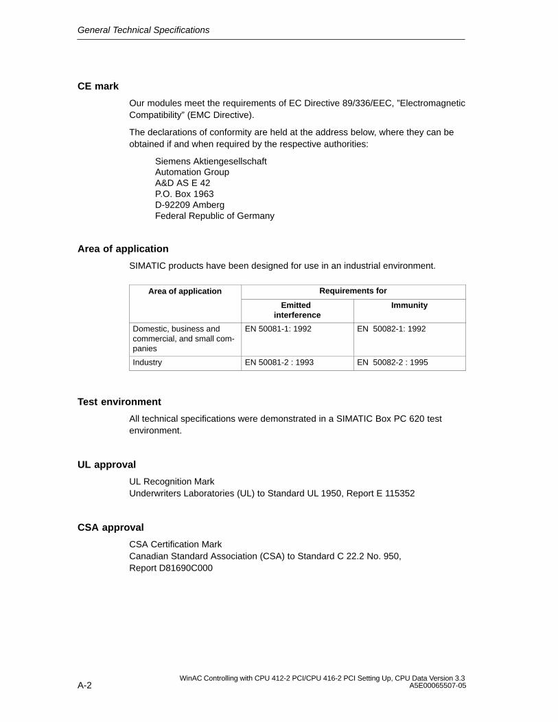
General Technical Specifications
A-2WinAC Controlling with CPU 412-2 PCI/CPU 416-2 PCI Setting Up, CPU Data Version 3.3
A5E00065507-05
CE mark
Our modules meet the requirements of EC Directive 89/336/EEC, ”ElectromagneticCompatibility” (EMC Directive).
The declarations of conformity are held at the address below, where they can beobtained if and when required by the respective authorities:
Siemens AktiengesellschaftAutomation Group A&D AS E 42P.O. Box 1963D-92209 AmbergFederal Republic of Germany
Area of application
SIMATIC products have been designed for use in an industrial environment.
Area of application Requirements for Emitted
interferenceImmunity
Domestic, business andcommercial, and small com-panies
EN 50081-1: 1992 EN 50082-1: 1992
Industry EN 50081-2 : 1993 EN 50082-2 : 1995
Test environment
All technical specifications were demonstrated in a SIMATIC Box PC 620 testenvironment.
UL approval
UL Recognition MarkUnderwriters Laboratories (UL) to Standard UL 1950, Report E 115352
CSA approval
CSA Certification MarkCanadian Standard Association (CSA) to Standard C 22.2 No. 950,Report D81690C000
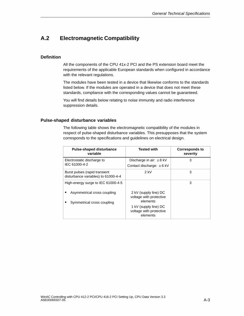
General Technical Specifications
A-3WinAC Controlling with CPU 412-2 PCI/CPU 416-2 PCI Setting Up, CPU Data Version 3.3A5E00065507-05
A.2 Electromagnetic Compatibility
Definition
All the components of the CPU 41x-2 PCI and the PS extension board meet therequirements of the applicable European standards when configured in accordancewith the relevant regulations.
The modules have been tested in a device that likewise conforms to the standardslisted below. If the modules are operated in a device that does not meet thesestandards, compliance with the corresponding values cannot be guaranteed.
You will find details below relating to noise immunity and radio interferencesuppression details.
Pulse-shaped disturbance variables
The following table shows the electromagnetic compatibility of the modules inrespect of pulse-shaped disturbance variables. This presupposes that the systemcorresponds to the specifications and guidelines on electrical design.
Pulse-shaped disturbancevariable
Tested with Corresponds toseverity
Electrostatic discharge toIEC 61000-4-2
Discharge in air: 8 kV
Contact discharge: 6 kV
3
Burst pulses (rapid transientdisturbance variables) to 61000-4-4
2 kV 3
High-energy surge to IEC 61000-4-5
Asymmetrical cross coupling
Symmetrical cross coupling
2 kV (supply line) DCvoltage with protective
elements
1 kV (supply line) DCvoltage with protective
elements
3
General Technical Specifications
A-4WinAC Controlling with CPU 412-2 PCI/CPU 416-2 PCI Setting Up, CPU Data Version 3.3
A5E00065507-05
Sinusoidal disturbance variables
The following table shows EMC behavior in respect of sinusoidal disturbancevariables:
Sinusoidal disturbancevariable
Tested with Correspondsto severity
RF irradiation (radiatedelectromagnetic field test) toIEC 61000-4-3
10 V/m with 80% amplitude modulationof 1 kHz over a range from 80 MHz to
1000 MHz
10 V/m with 50% pulse modulation at900 MHz
3
RF current application onlines and line screens toIEC 61000-4-6
Test voltage 10 V/m with 80% amplitudemodulation of 1 kHz over a range from
9 kHz to 80 MHz
3
Emission of radio interference
Radio interference suppression to EN 55022: limit value class B.
Working with the product
To protect the product from the electrostatic discharge, operating personnel musttake appropriate action to discharge their bodies before coming into contact withthe module.
A.3 Shipping and Storage Conditions
Modules
With regard to shipping and storage conditions, the modules meet therequirements of IEC 61131, Part 2. The following details apply to modules that areshipped and stored in their original packaging.
The climatic conditions conform to Class 2K4 for shipping and storage.
The mechanical conditions conform to IEC 60721, Part 3-2, Class 2M2.
Type of condition Permissible range
Free fall 1m (up to 10 kg)
Temperature From – 40 C to + 70C
Air pressure 1080 to 660 hPa (equivalent to a height of-1000 to 3500 m)
Relative humidity 5 to 95%, non-condensing
General Technical Specifications
A-5WinAC Controlling with CPU 412-2 PCI/CPU 416-2 PCI Setting Up, CPU Data Version 3.3A5E00065507-05
Type of condition Permissible range
Sinusoidal vibrations to IEC 60068-2-6 5 to 9 Hz: 3.5 mm
9 to 500 Hz: 9.8 m/s2
Mechanical shock to IEC 60068-2-29 250 m/s2, 6 ms, 1000 shocks
Shipping backup batteries
To the extent possible, ship backup batteries in their original packaging. No specialaction need be taken for shipping backup batteries. The lithium content of thebackup battery is less than 0.5 g.
Storing backup batteries
Store backup batteries in a cool and dry place. Their maximum shelf life is10 years.
!Warning
Risk of injury and material damage. Risk of hazardous substances escaping.
If handled wrongly, a lithium battery can explode; improper disposal of old lithiumbatteries may result in hazardous substances escaping. It is therefore imperativethat you comply with the following information:
Do not throw new or spent batteries into the fire and do not solder on the cellbody (maximum temperature of 100 °C); do not recharge as there is a risk ofexplosion.
Do not open the battery and replace it only with an identical type. Obtainreplacement batteries only from Siemens – this ensures that you possess ashort-circuit-proof type.
Return old batteries to the battery manufacturer, or dispose of them ashazardous waste.
Passivation layer
When lithium batteries (lithium/thionyl chloride) are used, a passivation layer mayform after very long periods of storage and cast doubt on the immediate ability ofthe battery to operate. Refer to section 4.4 for remedies.

General Technical Specifications
A-6WinAC Controlling with CPU 412-2 PCI/CPU 416-2 PCI Setting Up, CPU Data Version 3.3
A5E00065507-05
A.4 Mechanical and Climatic Environmental Conditions
Operating conditions
The modules have been tested in a device that likewise conforms to the standardslisted below. If the modules are operated in a device that does not meet thesestandards, compliance with the values cannot be guaranteed.
Usage with additional measures only
The CPU 41x-2 PCI and the PS extension board must not be used beforeadditional action, for example, has been taken
in locations subject to a high degree of ionizing radiation
at locations subject to difficult operating conditions; for example, due to
– occurrence of dust
– etching vapors or gases
– high electric or magnetic fields
on systems necessitating special monitoring, such as
– escalator systems
– electric systems in particularly hazardous areas.
An additional measure might be operation in a housing or cabinet, for example.
Mechanical environmental conditions
The SIMATIC Box PC 620 is designed to meet high demands on mechanicalambient conditions (oscillation test with 1 g constant loading at a frequency of 58 to500 Hz). CPUs 41x-2 PCI satisfy these requirements when used in a SIMATICBox PC 620.
When fitted to other PCs having slots that are longer than 3/4 PCI and subjected tohigh mechanical loads, you must mechanically fix the rear PCB end in position, ifnecessary.

General Technical Specifications
A-7WinAC Controlling with CPU 412-2 PCI/CPU 416-2 PCI Setting Up, CPU Data Version 3.3A5E00065507-05
Tests for mechanical environmental conditions
The table below provides information on the type and scope of tests for mechanicalenvironmental conditions.
Test for ...
Test standard Remarks
Vibrations Vibration testing toIEC 60068, Part 2-6 (sine)
Type of vibration: frequency sweeps with a changerate of 1 octave/minute.10 Hz f < 58 Hz, constant amplitude 0.075 mm58 Hz f < 500 Hz, constant acceleration 0.5 gVibration period: 10 frequency sweeps per axisalong each of tree mutually perpendicular axes
Impact Impact testing toIEC 60068, Part 2-29
Type of impact: half-sineForce of impact: 10 g peak value, 6 ms durationDirection of impact: 100 impacts along each ofthree mutually perpendicular axes
Climatic environmental conditions
The modules must be used under the following climatic environmental conditions:
Permissible range Remarks
Temperature 5 to +45 C
Temperaturechange
Max. 10 C/h
Relative humidity Max. 95% at +25 C Non-condensing, equivalentto RH stress level 2 toIEC 61131-2
Air pressure 1080 to 795 hPa (equivalent to aheight of –1000 to 2000 m)
Pollutant concen-tration SO2: < 0.5 ppm;
RH < 60%, non-condensingH2S: < 0.1 ppm;RH < 60%, non-condensing
Test:10 ppm; 4 days
1 ppm; 4 days
General Technical Specifications
A-8WinAC Controlling with CPU 412-2 PCI/CPU 416-2 PCI Setting Up, CPU Data Version 3.3
A5E00065507-05
A.5 Certification for USA, Canada and Australia
USA
Federal Communications CommissionRadio Frequency Interference Statement
This equipment has been tested and found to comply with the limits for a Class Adigital device, pursuant to Part 15 of the FCC Rules. These limits are designed toprovide reasonable protection against harmful interference when the equipment isoperated in a commercial environment. This equipment generates, uses and canradiate radio frequency energy and, if not installed and used in accordance with theinstruction manual, may cause harmful interference to radio communications.Operation of this equipment in a residential area is likely to cause harmfulinterference in which case the user will be required to correct the interference athis own expense:
Shielded cables
Shielded cables must be used with this equipment to maintain compliance withFCC regulations.
Modifications
Changes or modifications not expressly approved by the manufacturer could voidthe user’s authority to operate the equipment.
Conditions of operations
This device complies with Part 15 of the FCC Rules. Operation is subject to thefollowing two conditions: (1) this device may not cause harmful interference, and(2) this device must accept any interference received, including interference thatmay cause undesired operation.
Canada
Canadian Notice
This Class B digital apparatus complies with Canadian ICES-003.
Avis Canadien
Cet appareil numérique de la classe B est conforme à la norme NMB-003 duCanada.
Note for Australia
WinAC Slot 41x satisfies the requirements of Standard AS/NZS 3548 (Class B).
B-1WinAC Controlling with CPU 412-2 PCI/CPU 416-2 PCI Setting Up, CPU Data Version 3.3A5E00065507-05
Networking
In this chapter
Section Contents Page
B.1 Configuring an MPI or PROFIBUS Subnet B-1
B.2 Network Components B-1
B.3 Commissioning PROFIBUS-DP B-25
B.1 Configuring an MPI or PROFIBUS Subnet
In this chapter
Section Contents Page
B.1.1 Network Operation B-1
B.1.2 Fundamentals B-3
B.1.3 Rules for Configuring a Subnet B-5
B.1.4 Cable Lengths B-12
B.1.1 Network Operation
Networks
You can connect a CPU 41x-2 PCI
to an MPI subnet via the MPI
to a PROFIBUS–DP subnet via the PROFIBUS-DP interface orMPI/PROFIBUS-DP interface
to an Industrial Ethernet network via a SIMATIC Net CP – for example, a CP1613 – or an Ethernet module – for example, 3Com Card
to a PROFIBUS network via a SIMATIC Net CP – for example, a CP 5613.
B
Networking
B-2WinAC Controlling with CPU 412-2 PCI/CPU 416-2 PCI Setting Up, CPU Data Version 3.3
A5E00065507-05
Note
When using a SIMATIC Net CP and an Ethernet module simultaneously, you mustmake sure that the IP addresses are unique across both networks if you use theTCP/IP protocol (IP = Internet Protocol).
Identical configuration
The configuration of an MPI subnet is the same as for a PROFIBUS subnet. Thatmeans the same rules and the same components are used to configure thesubnet.
Since the structure of an MPI subnet does not differ from that of a PROFIBUSsubnet, general reference is made in the following sections to configuring a subnet.
Configuring communications
For the individual nodes of an MPI or PROFIBUS subnet to be able tocommunicate with each other, you have to assign them MPI and PROFIBUS-DPaddresses, respectively. The steps that have to be performed to assign theseaddresses and the points you have to watch out for are described in the manualConfiguring Hardware and Connections in STEP 7.
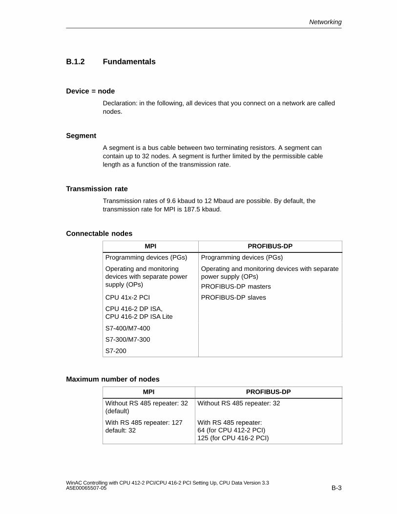
Networking
B-3WinAC Controlling with CPU 412-2 PCI/CPU 416-2 PCI Setting Up, CPU Data Version 3.3A5E00065507-05
B.1.2 Fundamentals
Device = node
Declaration: in the following, all devices that you connect on a network are callednodes.
Segment
A segment is a bus cable between two terminating resistors. A segment cancontain up to 32 nodes. A segment is further limited by the permissible cablelength as a function of the transmission rate.
Transmission rate
Transmission rates of 9.6 kbaud to 12 Mbaud are possible. By default, thetransmission rate for MPI is 187.5 kbaud.
Connectable nodes
MPI PROFIBUS-DP
Programming devices (PGs) Programming devices (PGs)
Operating and monitoringdevices with separate powersupply (OPs)
Operating and monitoring devices with separatepower supply (OPs)
PROFIBUS-DP masters
CPU 41x-2 PCI PROFIBUS-DP slaves
CPU 416-2 DP ISA,CPU 416-2 DP ISA Lite
S7-400/M7-400
S7-300/M7-300
S7-200
Maximum number of nodes
MPI PROFIBUS-DP
Without RS 485 repeater: 32(default)
Without RS 485 repeater: 32
With RS 485 repeater: 127default: 32
With RS 485 repeater:64 (for CPU 412-2 PCI)125 (for CPU 416-2 PCI)
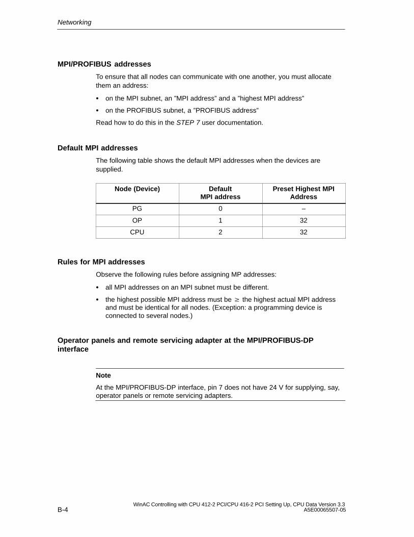
Networking
B-4WinAC Controlling with CPU 412-2 PCI/CPU 416-2 PCI Setting Up, CPU Data Version 3.3
A5E00065507-05
MPI/PROFIBUS addresses
To ensure that all nodes can communicate with one another, you must allocatethem an address:
on the MPI subnet, an ”MPI address” and a ”highest MPI address”
on the PROFIBUS subnet, a ”PROFIBUS address”
Read how to do this in the STEP 7 user documentation.
Default MPI addresses
The following table shows the default MPI addresses when the devices aresupplied.
Node (Device) DefaultMPI address
Preset Highest MPIAddress
PG 0 –
OP 1 32
CPU 2 32
Rules for MPI addresses
Observe the following rules before assigning MP addresses:
all MPI addresses on an MPI subnet must be different.
the highest possible MPI address must be the highest actual MPI addressand must be identical for all nodes. (Exception: a programming device isconnected to several nodes.)
Operator panels and remote servicing adapter at the MPI/PROFIBUS-DPinterface
Note
At the MPI/PROFIBUS-DP interface, pin 7 does not have 24 V for supplying, say,operator panels or remote servicing adapters.
Networking
B-5WinAC Controlling with CPU 412-2 PCI/CPU 416-2 PCI Setting Up, CPU Data Version 3.3A5E00065507-05
S7-200 on the MPI subnet
Set the proper transmission rate for the S7-200 at the MPI.
Note
At 19.2 kbaud for communications with the S7-200, no more than 8 nodes (CPU,PG/OP, FM/CP with separate MPI address) are allowed on a subnet. You mustnot configure global data communication.
B.1.3 Rules for Configuring a Subnet
In this subsection
This section describes how to configure a subnet and provides examples.
Rules
Observe the following rules for connecting nodes on a subnet:
Before you interconnect the individual nodes of the subnet you must assign theMPI address and the highest MPI address or the ”PROFIBUS address” and the”highest PROFIBUS address” to each node.
Mark all the nodes in a subnet by putting their address on their housings. In thisway, you can always see which node has been assigned which address in yoursystem.
Before you integrate a new node on the subnet, you must switch off its supplyvoltage.
Connect all nodes on the subnet ”in one line”; that is, integrate the stationaryprogramming devices and OPs direct on the subnet.
Connect only those programming devices/OPs that are required forcommissioning or maintenance via spur lines to the subnet.
If you operate more than 32 nodes on a PROFIBUS subnet, you must connectthe bus segments via RS 485 repeaters.
All bus segments in a PROFIBUS subnet must have at least one DP masterand one DP slave between them.
Connect ungrounded bus segments and grounded connected bus segments bymeans of RS 485 repeaters (refer to section B.2.4).
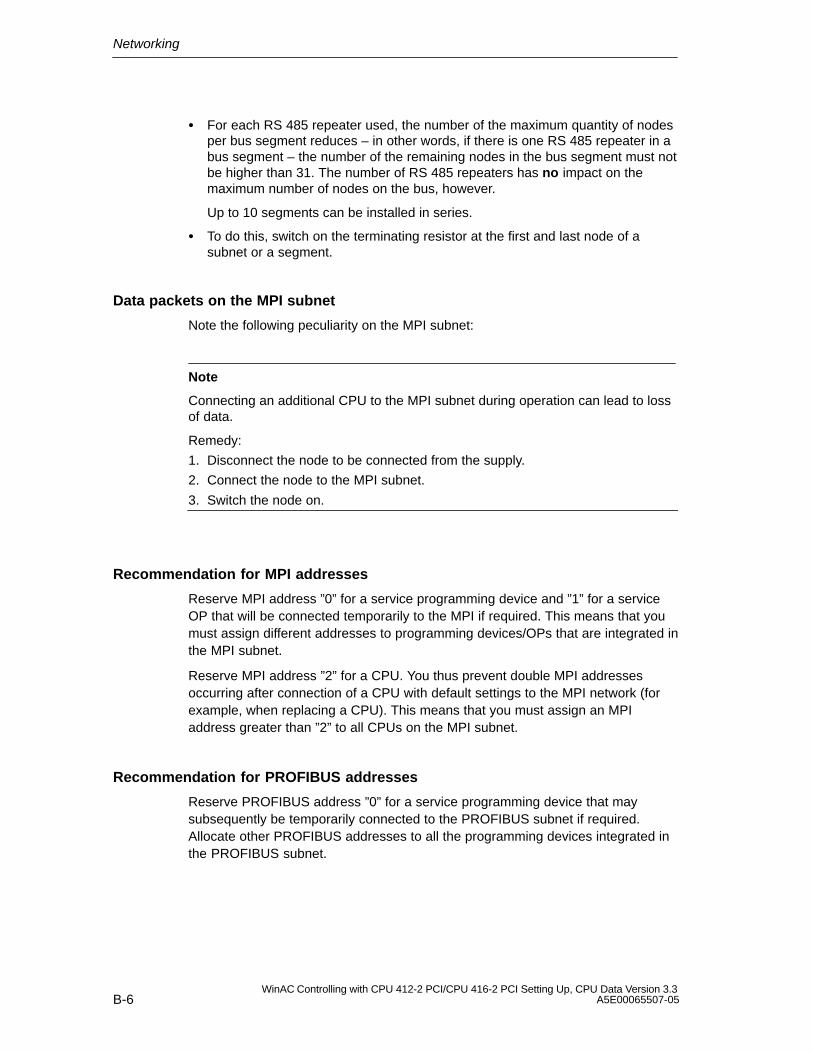
Networking
B-6WinAC Controlling with CPU 412-2 PCI/CPU 416-2 PCI Setting Up, CPU Data Version 3.3
A5E00065507-05
For each RS 485 repeater used, the number of the maximum quantity of nodesper bus segment reduces – in other words, if there is one RS 485 repeater in abus segment – the number of the remaining nodes in the bus segment must notbe higher than 31. The number of RS 485 repeaters has no impact on themaximum number of nodes on the bus, however.
Up to 10 segments can be installed in series.
To do this, switch on the terminating resistor at the first and last node of asubnet or a segment.
Data packets on the MPI subnet
Note the following peculiarity on the MPI subnet:
Note
Connecting an additional CPU to the MPI subnet during operation can lead to lossof data.
Remedy:
1. Disconnect the node to be connected from the supply.
2. Connect the node to the MPI subnet.
3. Switch the node on.
Recommendation for MPI addresses
Reserve MPI address ”0” for a service programming device and ”1” for a serviceOP that will be connected temporarily to the MPI if required. This means that youmust assign different addresses to programming devices/OPs that are integrated inthe MPI subnet.
Reserve MPI address ”2” for a CPU. You thus prevent double MPI addressesoccurring after connection of a CPU with default settings to the MPI network (forexample, when replacing a CPU). This means that you must assign an MPIaddress greater than ”2” to all CPUs on the MPI subnet.
Recommendation for PROFIBUS addresses
Reserve PROFIBUS address ”0” for a service programming device that maysubsequently be temporarily connected to the PROFIBUS subnet if required.Allocate other PROFIBUS addresses to all the programming devices integrated inthe PROFIBUS subnet.
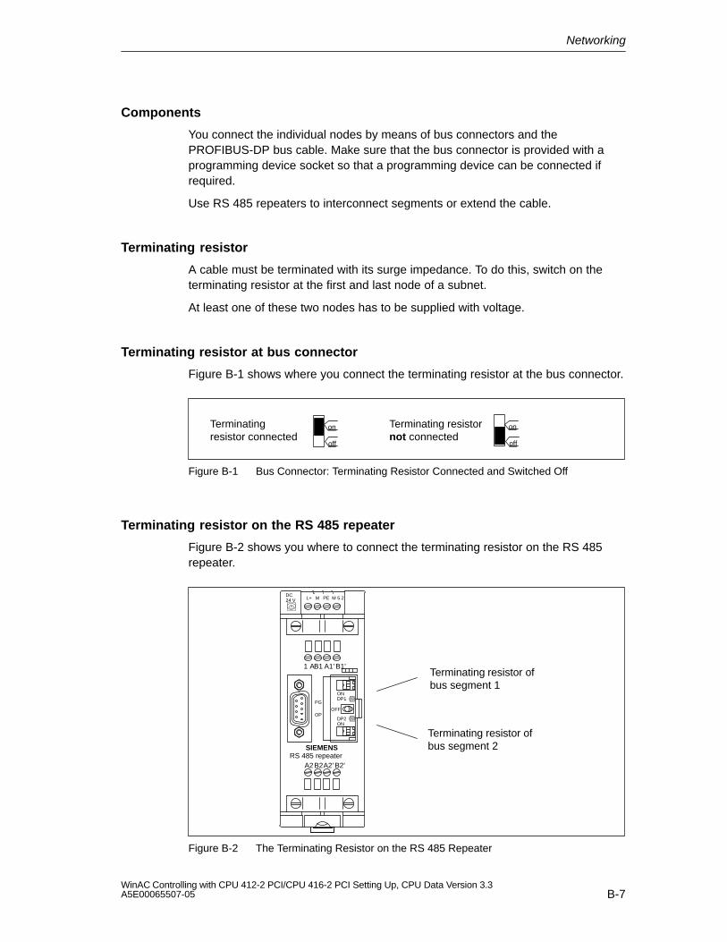
Networking
B-7WinAC Controlling with CPU 412-2 PCI/CPU 416-2 PCI Setting Up, CPU Data Version 3.3A5E00065507-05
Components
You connect the individual nodes by means of bus connectors and thePROFIBUS-DP bus cable. Make sure that the bus connector is provided with aprogramming device socket so that a programming device can be connected ifrequired.
Use RS 485 repeaters to interconnect segments or extend the cable.
Terminating resistor
A cable must be terminated with its surge impedance. To do this, switch on theterminating resistor at the first and last node of a subnet.
At least one of these two nodes has to be supplied with voltage.
Terminating resistor at bus connector
Figure B-1 shows where you connect the terminating resistor at the bus connector.
Terminatingresistor connected
Terminating resistornot connected
on
off
on
off
Figure B-1 Bus Connector: Terminating Resistor Connected and Switched Off
Terminating resistor on the RS 485 repeater
Figure B-2 shows you where to connect the terminating resistor on the RS 485repeater.
Terminating resistor ofbus segment 1
Terminating resistor ofbus segment 2
DC24 V L+ M PE M 5.2
1 AB1 A1’ B1’
A2B2A2’ B2’
SIEMENSRS 485 repeater
ON
ON
DP2
DP1
OFF
PG
OP
Figure B-2 The Terminating Resistor on the RS 485 Repeater
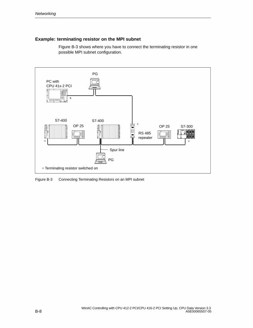
Networking
B-8WinAC Controlling with CPU 412-2 PCI/CPU 416-2 PCI Setting Up, CPU Data Version 3.3
A5E00065507-05
Example: terminating resistor on the MPI subnet
Figure B-3 shows where you have to connect the terminating resistor in onepossible MPI subnet configuration.
RS 485repeater
+
+
+
+ Terminating resistor switched on
S7-400 S7-400
PC with CPU 41x-2 PCI
Spur line
S7-300
+
OP 25 OP 25
PG
PG
Figure B-3 Connecting Terminating Resistors on an MPI subnet
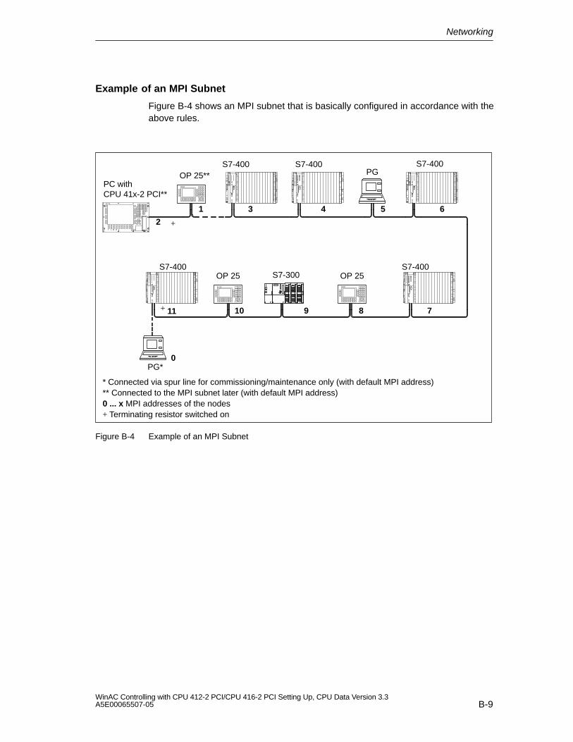
Networking
B-9WinAC Controlling with CPU 412-2 PCI/CPU 416-2 PCI Setting Up, CPU Data Version 3.3A5E00065507-05
Example of an MPI Subnet
Figure B-4 shows an MPI subnet that is basically configured in accordance with theabove rules.
* Connected via spur line for commissioning/maintenance only (with default MPI address)** Connected to the MPI subnet later (with default MPI address)0 ... x MPI addresses of the nodes+ Terminating resistor switched on
S7-400 S7-400 S7-400
S7-400 S7-400
0
11 78910
1
2
3 4 5 6
PG*
OP 25 OP 25
PGOP 25**
+
+
S7-300
PC withCPU 41x-2 PCI**
Figure B-4 Example of an MPI Subnet
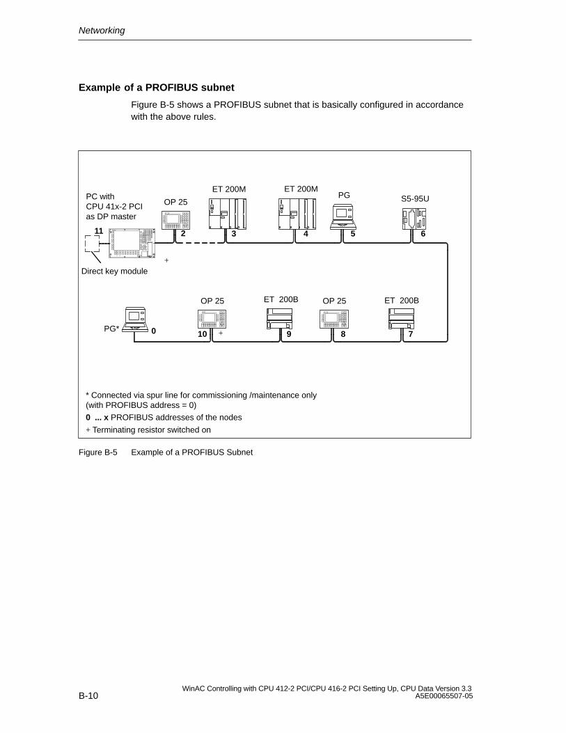
Networking
B-10WinAC Controlling with CPU 412-2 PCI/CPU 416-2 PCI Setting Up, CPU Data Version 3.3
A5E00065507-05
Example of a PROFIBUS subnet
Figure B-5 shows a PROFIBUS subnet that is basically configured in accordancewith the above rules.
* Connected via spur line for commissioning /maintenance only (with PROFIBUS address = 0)
0 ... x PROFIBUS addresses of the nodes
PC withCPU 41x-2 PCIas DP master
ET 200M
0 78910
2 3 4 5 6
PG*
OP 25 OP 25
OP 25
ET 200M
+
+ Terminating resistor switched on
+
Direct key module
PG S5-95U
ET 200BET 200B
11
Figure B-5 Example of a PROFIBUS Subnet
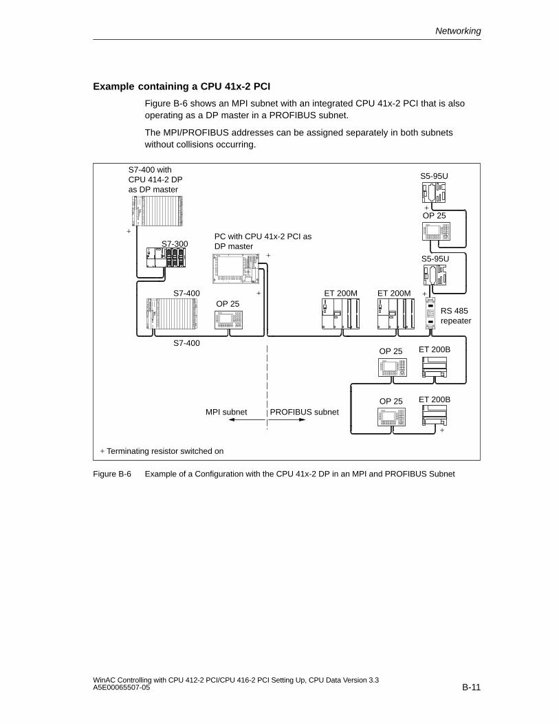
Networking
B-11WinAC Controlling with CPU 412-2 PCI/CPU 416-2 PCI Setting Up, CPU Data Version 3.3A5E00065507-05
Example containing a CPU 41x-2 PCI
Figure B-6 shows an MPI subnet with an integrated CPU 41x-2 PCI that is alsooperating as a DP master in a PROFIBUS subnet.
The MPI/PROFIBUS addresses can be assigned separately in both subnetswithout collisions occurring.
+ Terminating resistor switched on
OP 25
S7-400 withCPU 414-2 DPas DP master
ET 200M
ET 200B
RS 485repeater
S7-400
S7-400
ET 200M
ET 200BOP 25
+
OP 25
+
+
+
S7-300PC with CPU 41x-2 PCI asDP master
+
+
MPI subnet PROFIBUS subnet
S5-95U
OP 25
S5-95U
Figure B-6 Example of a Configuration with the CPU 41x-2 DP in an MPI and PROFIBUS Subnet
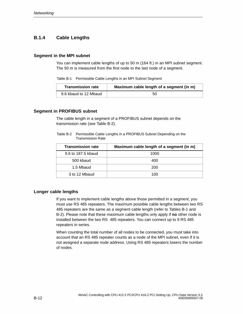
Networking
B-12WinAC Controlling with CPU 412-2 PCI/CPU 416-2 PCI Setting Up, CPU Data Version 3.3
A5E00065507-05
B.1.4 Cable Lengths
Segment in the MPI subnet
You can implement cable lengths of up to 50 m (164 ft.) in an MPI subnet segment.The 50 m is measured from the first node to the last node of a segment.
Table B-1 Permissible Cable Lengths in an MPI Subnet Segment
Transmission rate Maximum cable length of a segment (in m)
9.6 kbaud to 12 Mbaud 50
Segment in PROFIBUS subnet
The cable length in a segment of a PROFIBUS subnet depends on thetransmission rate (see Table B-2).
Table B-2 Permissible Cable Lengths in a PROFIBUS Subnet Depending on theTransmission Rate
Transmission rate Maximum cable length of a segment (in m)
9.6 to 187.5 kbaud 1000
500 kbaud 400
1.5 Mbaud 200
3 to 12 Mbaud 100
Longer cable lengths
If you want to implement cable lengths above those permitted in a segment, youmust use RS 485 repeaters. The maximum possible cable lengths between two RS485 repeaters are the same as a segment cable length (refer to Tables B-1 andB-2). Please note that these maximum cable lengths only apply if no other node isinstalled between the two RS 485 repeaters. You can connect up to 9 RS 485repeaters in series.
When counting the total number of all nodes to be connected, you must take intoaccount that an RS 485 repeater counts as a node of the MPI subnet, even if it isnot assigned a separate node address. Using RS 485 repeaters lowers the numberof nodes.
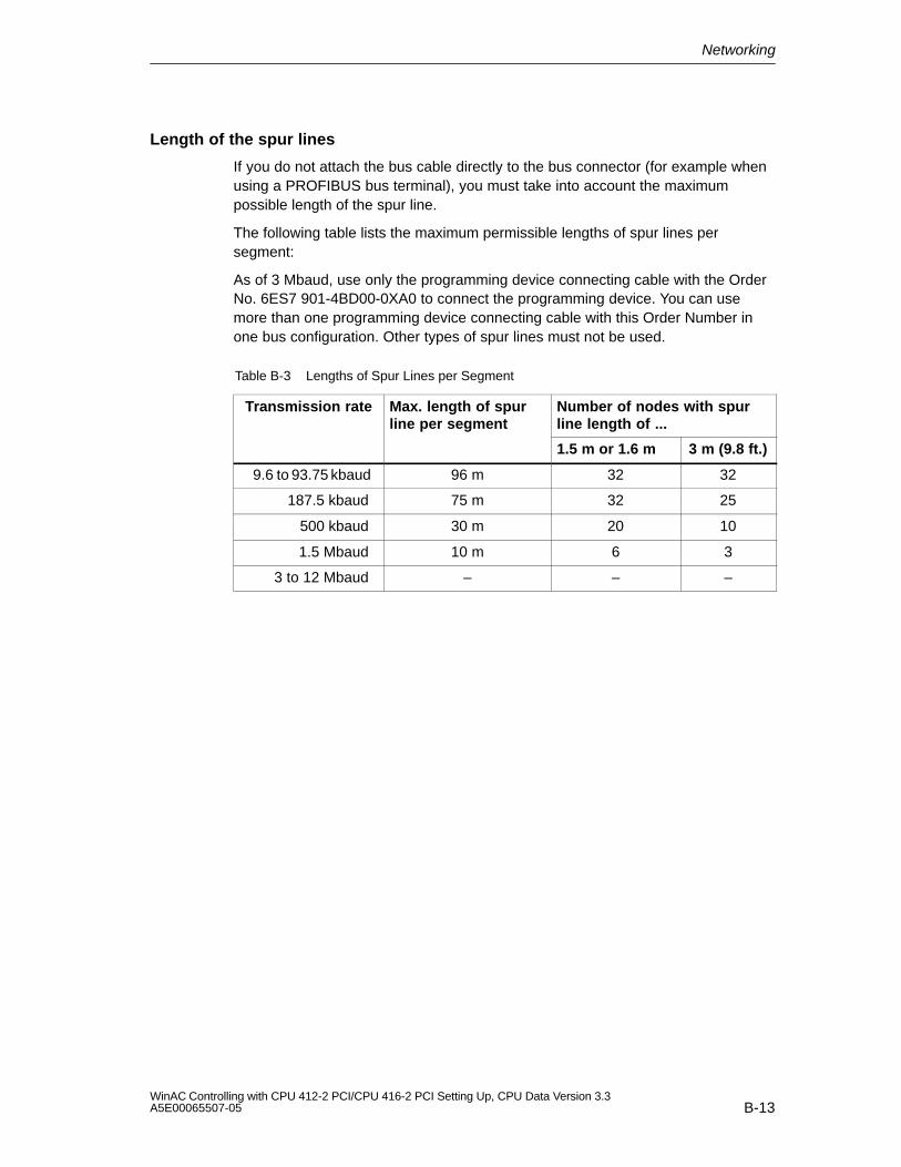
Networking
B-13WinAC Controlling with CPU 412-2 PCI/CPU 416-2 PCI Setting Up, CPU Data Version 3.3A5E00065507-05
Length of the spur lines
If you do not attach the bus cable directly to the bus connector (for example whenusing a PROFIBUS bus terminal), you must take into account the maximumpossible length of the spur line.
The following table lists the maximum permissible lengths of spur lines persegment:
As of 3 Mbaud, use only the programming device connecting cable with the OrderNo. 6ES7 901-4BD00-0XA0 to connect the programming device. You can usemore than one programming device connecting cable with this Order Number inone bus configuration. Other types of spur lines must not be used.
Table B-3 Lengths of Spur Lines per Segment
Transmission rate Max. length of spurline per segment
Number of nodes with spurline length of ...
1.5 m or 1.6 m 3 m (9.8 ft.)
9.6 to 93.75 kbaud 96 m 32 32
187.5 kbaud 75 m 32 25
500 kbaud 30 m 20 10
1.5 Mbaud 10 m 6 3
3 to 12 Mbaud – – –
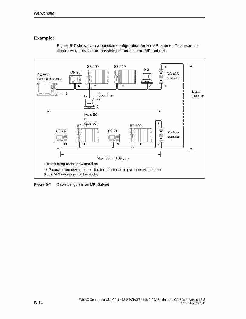
Networking
B-14WinAC Controlling with CPU 412-2 PCI/CPU 416-2 PCI Setting Up, CPU Data Version 3.3
A5E00065507-05
Example:
Figure B-7 shows you a possible configuration for an MPI subnet. This exampleillustrates the maximum possible distances in an MPI subnet.
Max. 50m(109 yd.)
Max. 50 m (109 yd.)
Max.1000 m
+ Terminating resistor switched on
++ Programming device connected for maintenance purposes via spur line0 ... x MPI addresses of the nodes
RS 485repeater
RS 485repeater
+
+
+
+
+
+
S7-400 S7-400
S7-400 S7-400
Spur line++
0
11
7
8910
3
4 5 6
OP 25
PG
PG
OP 25
OP 25PC withCPU 41x-2 PCI
Figure B-7 Cable Lengths in an MPI Subnet
Networking
B-15WinAC Controlling with CPU 412-2 PCI/CPU 416-2 PCI Setting Up, CPU Data Version 3.3A5E00065507-05
B.2 Network Components
In this chapter
This section describes the properties of the network components and informationfor their installation and handling.
Section Contents Page
B.2.1 PROFIBUS Bus Cable B-15
B.2.2 Bus Connector B-17
B.2.3 Plugging the Bus Connector into Modules B-18
B.2.4 RS 485 Repeater B-20
B.2.5 RS 485 Repeater in Ungrounded and Grounded Mode B-22
B.2.6 Technical Specifications of the RS 485 Repeater B-24
B.2.1 PROFIBUS Bus Cable
Purpose
Table B-4 Network Components
Purpose Components Description
... to configure a network PROFIBUS bus cable Section B.2.1
... to connect a node to thenetwork
Bus connector Section B.2.2
... to amplify the signal
... to connect segments
RS 485 Repeater Section B.2.4
... to convert the signal for afiber-optic network (forPROFIBUS-DP network only)
Optical link module In the manual SIMATIC NETPROFIBUS Networks
... to connect programmingdevices/OPs to the network
Programming device connectingcables (spur lines)
Section B.1.4
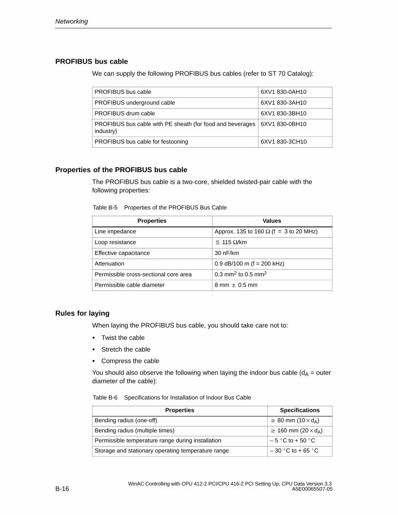
Networking
B-16WinAC Controlling with CPU 412-2 PCI/CPU 416-2 PCI Setting Up, CPU Data Version 3.3
A5E00065507-05
PROFIBUS bus cable
We can supply the following PROFIBUS bus cables (refer to ST 70 Catalog):
PROFIBUS bus cable 6XV1 830-0AH10
PROFIBUS underground cable 6XV1 830-3AH10
PROFIBUS drum cable 6XV1 830-3BH10
PROFIBUS bus cable with PE sheath (for food and beveragesindustry)
6XV1 830-0BH10
PROFIBUS bus cable for festooning 6XV1 830-3CH10
Properties of the PROFIBUS bus cable
The PROFIBUS bus cable is a two-core, shielded twisted-pair cable with thefollowing properties:
Table B-5 Properties of the PROFIBUS Bus Cable
Properties Values
Line impedance Approx. 135 to 160 Ω (f = 3 to 20 MHz)
Loop resistance 115 Ω/km
Effective capacitance 30 nF/km
Attenuation 0.9 dB/100 m (f = 200 kHz)
Permissible cross-sectional core area 0.3 mm2 to 0.5 mm2
Permissible cable diameter 8 mm 0.5 mm
Rules for laying
When laying the PROFIBUS bus cable, you should take care not to:
Twist the cable
Stretch the cable
Compress the cable
You should also observe the following when laying the indoor bus cable (dA = outerdiameter of the cable):
Table B-6 Specifications for Installation of Indoor Bus Cable
Properties Specifications
Bending radius (one-off) 80 mm (10dA)
Bending radius (multiple times) 160 mm (20dA)
Permissible temperature range during installation – 5 C to + 50 C
Storage and stationary operating temperature range – 30 C to + 65 C
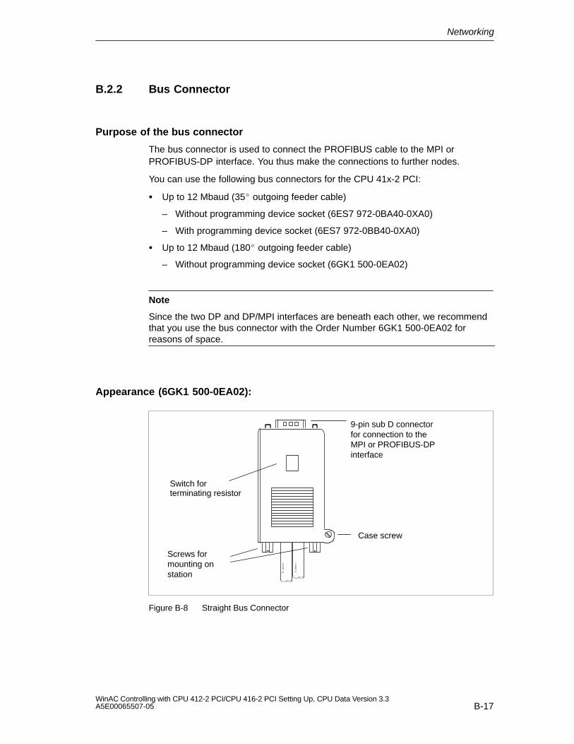
Networking
B-17WinAC Controlling with CPU 412-2 PCI/CPU 416-2 PCI Setting Up, CPU Data Version 3.3A5E00065507-05
B.2.2 Bus Connector
Purpose of the bus connector
The bus connector is used to connect the PROFIBUS cable to the MPI orPROFIBUS-DP interface. You thus make the connections to further nodes.
You can use the following bus connectors for the CPU 41x-2 PCI:
Up to 12 Mbaud (35 outgoing feeder cable)
– Without programming device socket (6ES7 972-0BA40-0XA0)
– With programming device socket (6ES7 972-0BB40-0XA0)
Up to 12 Mbaud (180 outgoing feeder cable)
– Without programming device socket (6GK1 500-0EA02)
Note
Since the two DP and DP/MPI interfaces are beneath each other, we recommendthat you use the bus connector with the Order Number 6GK1 500-0EA02 forreasons of space.
Appearance (6GK1 500-0EA02):
9-pin sub D connectorfor connection to theMPI or PROFIBUS-DPinterface
Case screw
Screws formounting onstation
Switch for terminating resistor
Figure B-8 Straight Bus Connector
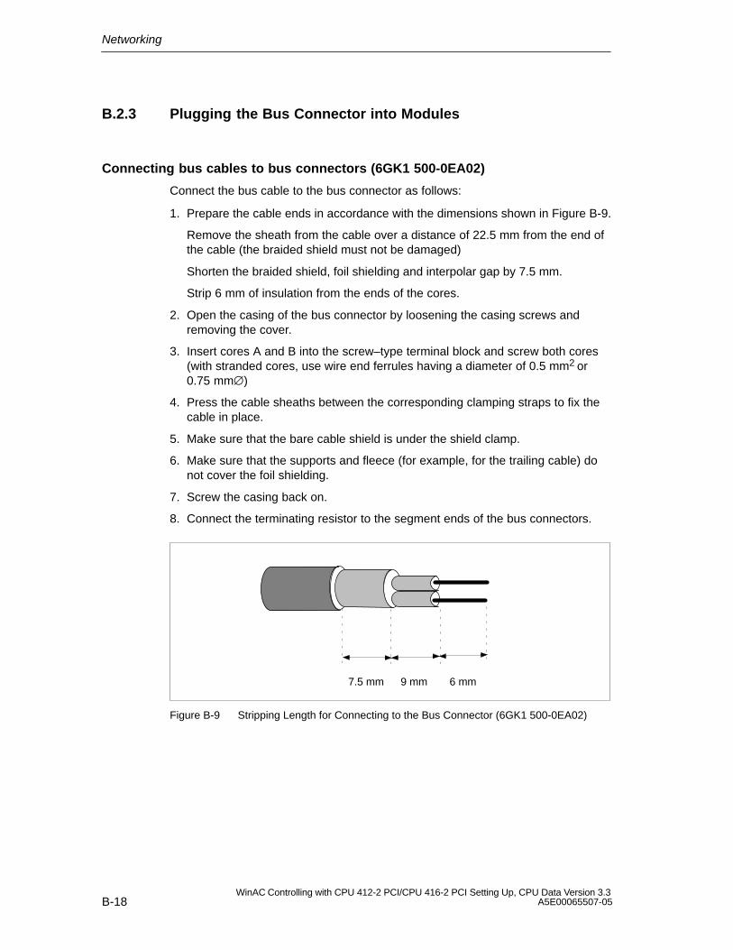
Networking
B-18WinAC Controlling with CPU 412-2 PCI/CPU 416-2 PCI Setting Up, CPU Data Version 3.3
A5E00065507-05
B.2.3 Plugging the Bus Connector into Modules
Connecting bus cables to bus connectors (6GK1 500-0EA02)
Connect the bus cable to the bus connector as follows:
1. Prepare the cable ends in accordance with the dimensions shown in Figure B-9.
Remove the sheath from the cable over a distance of 22.5 mm from the end ofthe cable (the braided shield must not be damaged)
Shorten the braided shield, foil shielding and interpolar gap by 7.5 mm.
Strip 6 mm of insulation from the ends of the cores.
2. Open the casing of the bus connector by loosening the casing screws andremoving the cover.
3. Insert cores A and B into the screw–type terminal block and screw both cores(with stranded cores, use wire end ferrules having a diameter of 0.5 mm2 or0.75 mm∅)
4. Press the cable sheaths between the corresponding clamping straps to fix thecable in place.
5. Make sure that the bare cable shield is under the shield clamp.
6. Make sure that the supports and fleece (for example, for the trailing cable) donot cover the foil shielding.
7. Screw the casing back on.
8. Connect the terminating resistor to the segment ends of the bus connectors.
6 mm9 mm7.5 mm
Figure B-9 Stripping Length for Connecting to the Bus Connector (6GK1 500-0EA02)
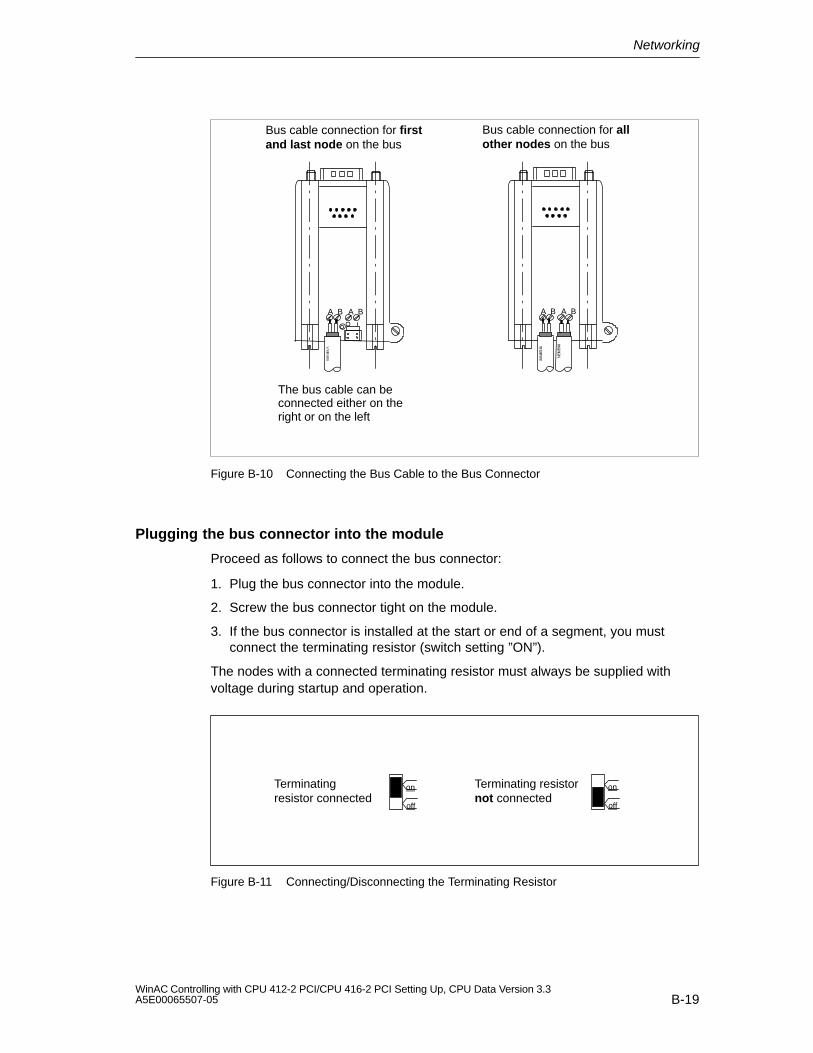
Networking
B-19WinAC Controlling with CPU 412-2 PCI/CPU 416-2 PCI Setting Up, CPU Data Version 3.3A5E00065507-05
A B A B A B A B
Bus cable connection for firstand last node on the bus
Bus cable connection for allother nodes on the bus
The bus cable can beconnected either on theright or on the left
ÇÇÇÇ
Figure B-10 Connecting the Bus Cable to the Bus Connector
Plugging the bus connector into the module
Proceed as follows to connect the bus connector:
1. Plug the bus connector into the module.
2. Screw the bus connector tight on the module.
3. If the bus connector is installed at the start or end of a segment, you mustconnect the terminating resistor (switch setting ”ON”).
The nodes with a connected terminating resistor must always be supplied withvoltage during startup and operation.
Terminatingresistor connected
Terminating resistornot connected
on
off
on
off
Figure B-11 Connecting/Disconnecting the Terminating Resistor
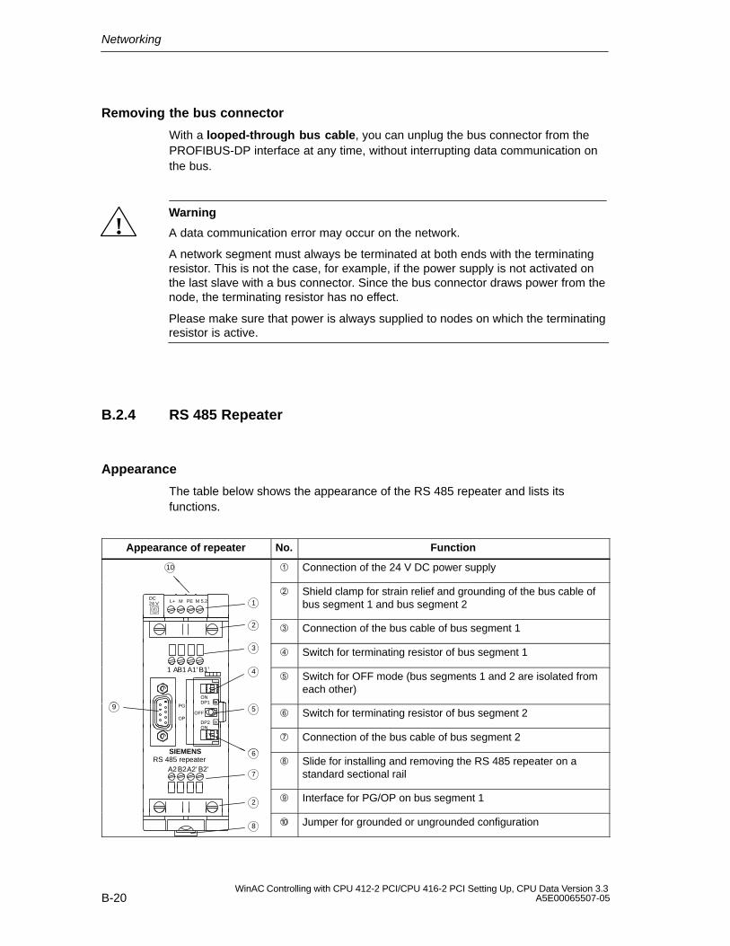
Networking
B-20WinAC Controlling with CPU 412-2 PCI/CPU 416-2 PCI Setting Up, CPU Data Version 3.3
A5E00065507-05
Removing the bus connector
With a looped-through bus cable, you can unplug the bus connector from thePROFIBUS-DP interface at any time, without interrupting data communication onthe bus.
!Warning
A data communication error may occur on the network.
A network segment must always be terminated at both ends with the terminatingresistor. This is not the case, for example, if the power supply is not activated onthe last slave with a bus connector. Since the bus connector draws power from thenode, the terminating resistor has no effect.
Please make sure that power is always supplied to nodes on which the terminatingresistor is active.
B.2.4 RS 485 Repeater
Appearance
The table below shows the appearance of the RS 485 repeater and lists itsfunctions.
Appearance of repeater No. Function
10 Connection of the 24 V DC power supply
DC24 V L+ M PE M 5.2 1
Shield clamp for strain relief and grounding of the bus cable ofbus segment 1 and bus segment 2
2 Connection of the bus cable of bus segment 1
3 Switch for terminating resistor of bus segment 1
1 AB1 A1’ B1’
ON
4 Switch for OFF mode (bus segments 1 and 2 are isolated from
each other)
DP2
DP1
OFF
PG
OP
59 Switch for terminating resistor of bus segment 2
ONDP2
Connection of the bus cable of bus segment 2
A2B2A2’ B2’
SIEMENSRS 485 repeater
6
7
Slide for installing and removing the RS 485 repeater on astandard sectional rail
2
Interface for PG/OP on bus segment 1
8 Jumper for grounded or ungrounded configuration
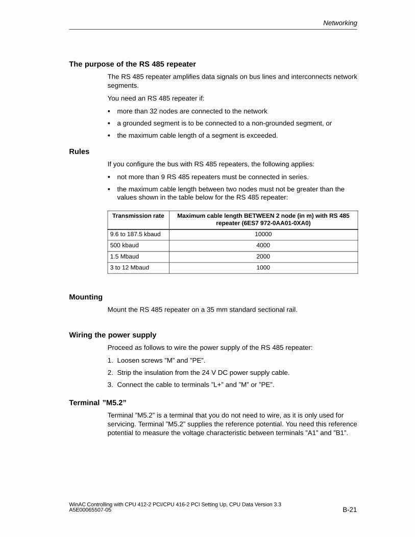
Networking
B-21WinAC Controlling with CPU 412-2 PCI/CPU 416-2 PCI Setting Up, CPU Data Version 3.3A5E00065507-05
The purpose of the RS 485 repeater
The RS 485 repeater amplifies data signals on bus lines and interconnects networksegments.
You need an RS 485 repeater if:
more than 32 nodes are connected to the network
a grounded segment is to be connected to a non-grounded segment, or
the maximum cable length of a segment is exceeded.
Rules
If you configure the bus with RS 485 repeaters, the following applies:
not more than 9 RS 485 repeaters must be connected in series.
the maximum cable length between two nodes must not be greater than thevalues shown in the table below for the RS 485 repeater:
Transmission rate Maximum cable length BETWEEN 2 node (in m) with RS 485repeater (6ES7 972-0AA01-0XA0)
9.6 to 187.5 kbaud 10000
500 kbaud 4000
1.5 Mbaud 2000
3 to 12 Mbaud 1000
Mounting
Mount the RS 485 repeater on a 35 mm standard sectional rail.
Wiring the power supply
Proceed as follows to wire the power supply of the RS 485 repeater:
1. Loosen screws ”M” and ”PE”.
2. Strip the insulation from the 24 V DC power supply cable.
3. Connect the cable to terminals ”L+” and ”M” or ”PE”.
Terminal ”M5.2”
Terminal ”M5.2” is a terminal that you do not need to wire, as it is only used forservicing. Terminal ”M5.2” supplies the reference potential. You need this referencepotential to measure the voltage characteristic between terminals ”A1” and ”B1”.
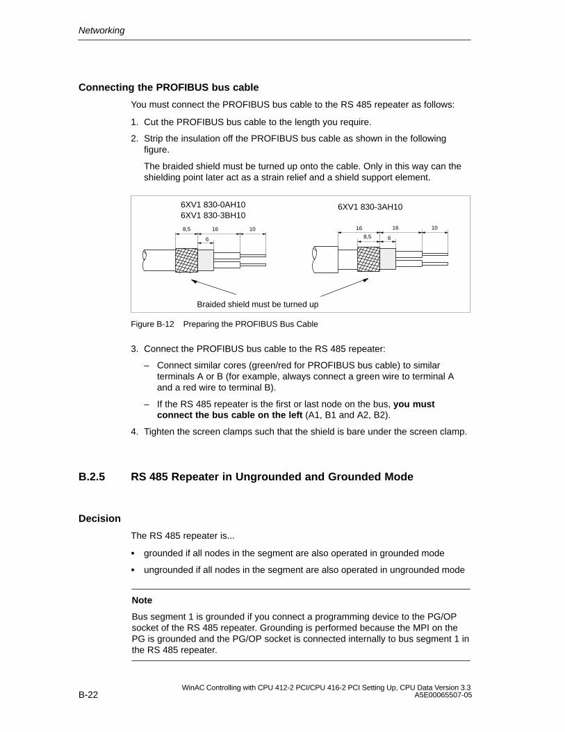
Networking
B-22WinAC Controlling with CPU 412-2 PCI/CPU 416-2 PCI Setting Up, CPU Data Version 3.3
A5E00065507-05
Connecting the PROFIBUS bus cable
You must connect the PROFIBUS bus cable to the RS 485 repeater as follows:
1. Cut the PROFIBUS bus cable to the length you require.
2. Strip the insulation off the PROFIBUS bus cable as shown in the followingfigure.
The braided shield must be turned up onto the cable. Only in this way can theshielding point later act as a strain relief and a shield support element.
Braided shield must be turned up
6XV1 830-0AH106XV1 830-3BH10
6XV1 830-3AH10
8,5 16 10
6 8,5
16 10
6
16
Figure B-12 Preparing the PROFIBUS Bus Cable
3. Connect the PROFIBUS bus cable to the RS 485 repeater:
– Connect similar cores (green/red for PROFIBUS bus cable) to similarterminals A or B (for example, always connect a green wire to terminal Aand a red wire to terminal B).
– If the RS 485 repeater is the first or last node on the bus, you mustconnect the bus cable on the left (A1, B1 and A2, B2).
4. Tighten the screen clamps such that the shield is bare under the screen clamp.
B.2.5 RS 485 Repeater in Ungrounded and Grounded Mode
Decision
The RS 485 repeater is...
grounded if all nodes in the segment are also operated in grounded mode
ungrounded if all nodes in the segment are also operated in ungrounded mode
Note
Bus segment 1 is grounded if you connect a programming device to the PG/OPsocket of the RS 485 repeater. Grounding is performed because the MPI on thePG is grounded and the PG/OP socket is connected internally to bus segment 1 inthe RS 485 repeater.
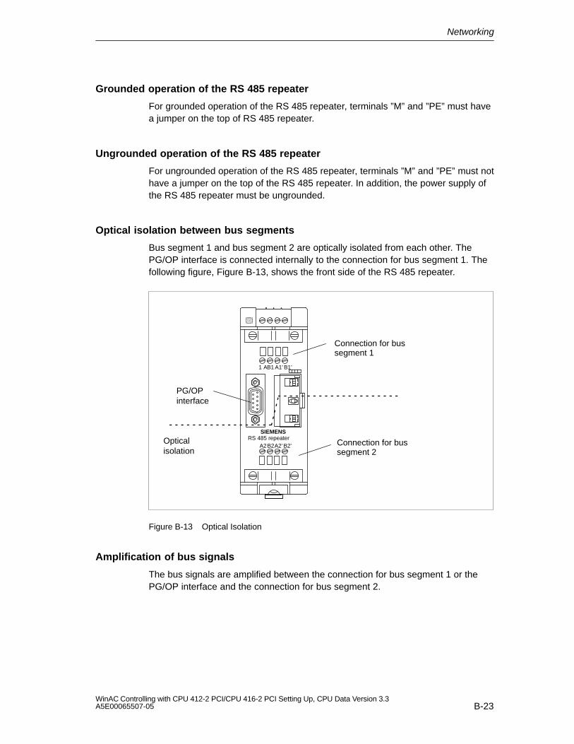
Networking
B-23WinAC Controlling with CPU 412-2 PCI/CPU 416-2 PCI Setting Up, CPU Data Version 3.3A5E00065507-05
Grounded operation of the RS 485 repeater
For grounded operation of the RS 485 repeater, terminals ”M” and ”PE” must havea jumper on the top of RS 485 repeater.
Ungrounded operation of the RS 485 repeater
For ungrounded operation of the RS 485 repeater, terminals ”M” and ”PE” must nothave a jumper on the top of the RS 485 repeater. In addition, the power supply ofthe RS 485 repeater must be ungrounded.
Optical isolation between bus segments
Bus segment 1 and bus segment 2 are optically isolated from each other. The PG/OP interface is connected internally to the connection for bus segment 1. Thefollowing figure, Figure B-13, shows the front side of the RS 485 repeater.
Opticalisolation
PG/OPinterface
Connection for bussegment 1
Connection for bussegment 2
1 AB1 A1’ B1’
A2B2A2’ B2’
SIEMENSRS 485 repeater
Figure B-13 Optical Isolation
Amplification of bus signals
The bus signals are amplified between the connection for bus segment 1 or thePG/OP interface and the connection for bus segment 2.
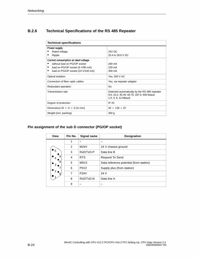
Networking
B-24WinAC Controlling with CPU 412-2 PCI/CPU 416-2 PCI Setting Up, CPU Data Version 3.3
A5E00065507-05
B.2.6 Technical Specifications of the RS 485 Repeater
Technical specifications
Power supplyPower supply Rated voltage 24V DC Ripple 20.4 to 28.8 V DC
Current consumption at rated voltageCurrent consumption at rated voltage without load on PG/OP socket 200 mA load on PG/OP socket (5 V/90 mA) 230 mA load on PG/OP socket (24 V/100 mA) 300 mA
Optical isolation Yes, 500 V AC
Connection of fiber–optic cables Yes, via repeater adapter
Redundant operation No
Transmission rate Detected automatically by the RS 485 repeater 9.6; 19.2; 45.45; 93.75; 187.5; 500 kbaud1.5; 3; 6; 12 Mbaud
Degree of protection IP 20
Dimensions W H D (in mm) 45 128 67
Weight (incl. packing) 350 g
Pin assignment of the sub D connector (PG/OP socket)
View Pin No. Signal name Designation
1 – –
2 M24V 24 V chassis ground5 3 RxD/TxD-P Data line B
94 4 RTS Request To Send4
8 5 M5V2 Data reference potential (from station)3
7 6 P5V2 Supply plus (from station)2
6 7 P24V 24 V1 8 RxD/TxD-N Data line A
9 – –
Networking
B-25WinAC Controlling with CPU 412-2 PCI/CPU 416-2 PCI Setting Up, CPU Data Version 3.3A5E00065507-05
B.3 Commissioning PROFIBUS-DP
Introduction
This section describes the steps you have to perform when you commission aPROFIBUS-DP network with a CPU 41x-2 PCI as a DP master.
Requirements
Before you can commission the PROFIBUS-DP network, the followingrequirements have to be met:
The PROFIBUS-DP network is connected (refer to section 6.3).
You have configured the PROFIBUS-DP network in STEP 7 and assigned aPROFIBUS-DP address and address space to each node (refer to the manualConfiguring Hardware and Connections in STEP 7 Version 5.0). Note that withsome DP slaves you also have to set address switches (refer to the descriptionof the DP slaves in question).
Commissioning
Perform the following steps to commission the PROFIBUS-DP network:
1. Load the configuration you created in STEP 7 for the PROFIBUS-DP network(setpoint configuration) with the programming device into the CPU. Theprocedure for this is described in the STEP 7 user guide.
2. Switch on all of the DP slaves.
3. Switch the CPU from STOP to RUN.
CPU behavior during startup
During startup, the CPU compares the setpoint configuration with the actualconfiguration. Set the time it takes for the comparison in STEP 7 with the ”ModuleTime Limits” parameter in the ”Startup” parameter field when assigning parametersto the module.
If the setpoint configuration is identical to the actual configuration, the CPU goes toRUN.
If the setpoint configuration is not the same as the actual configuration, thebehavior of the CPU depends on the setting of the parameter ”Startup whenSetpoint Not equal to Actual Configuration”
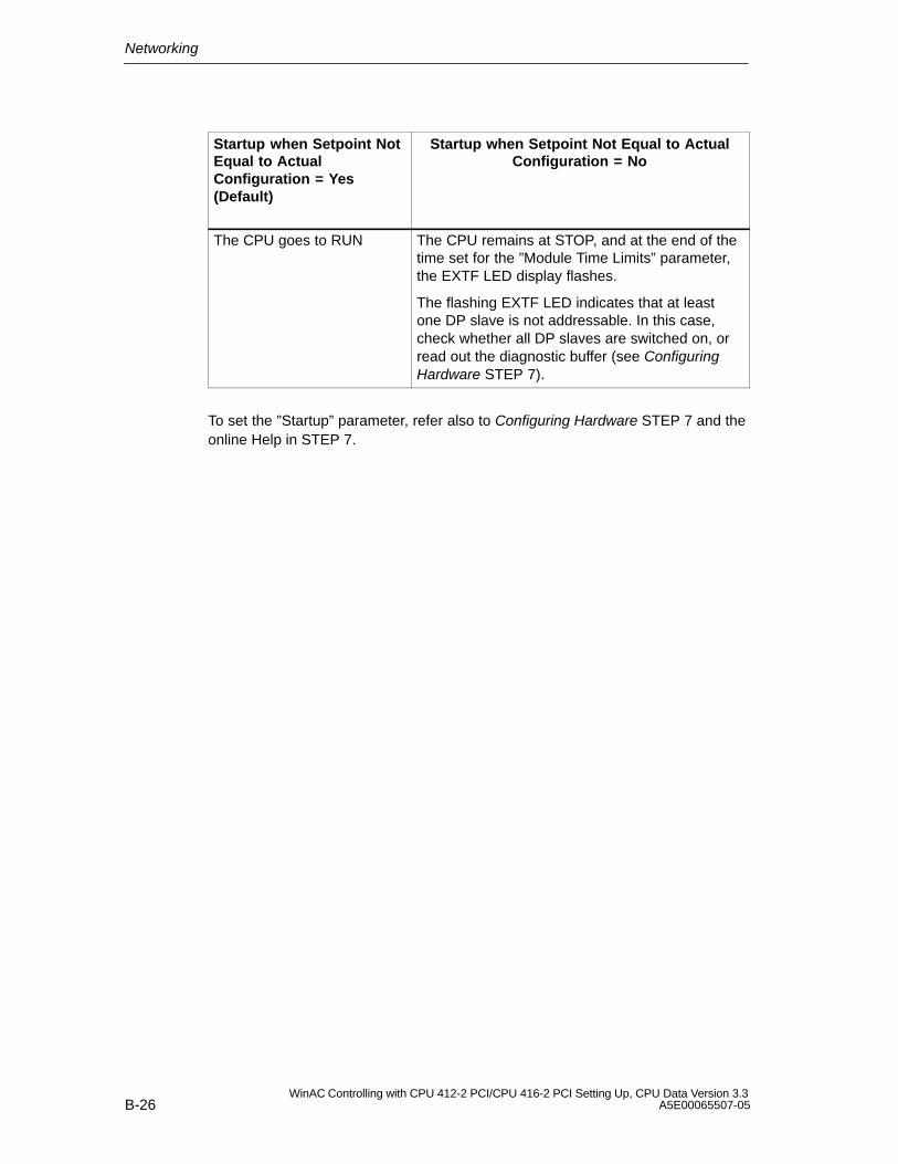
Networking
B-26WinAC Controlling with CPU 412-2 PCI/CPU 416-2 PCI Setting Up, CPU Data Version 3.3
A5E00065507-05
Startup when Setpoint NotEqual to ActualConfiguration = Yes(Default)
Startup when Setpoint Not Equal to ActualConfiguration = No
The CPU goes to RUN The CPU remains at STOP, and at the end of thetime set for the ”Module Time Limits” parameter,the EXTF LED display flashes.
The flashing EXTF LED indicates that at leastone DP slave is not addressable. In this case,check whether all DP slaves are switched on, orread out the diagnostic buffer (see ConfiguringHardware STEP 7).
To set the ”Startup” parameter, refer also to Configuring Hardware STEP 7 and theonline Help in STEP 7.

C-1WinAC Controlling with CPU 412-2 PCI/CPU 416-2 PCI Setting Up, CPU Data Version 3.3A5E00065507-05
FAQs: Frequently Asked Questions aboutWinAC Slot 41x
In this chapter
Section Description Page
Questions relating to the PS extension board
C.1 When do I use the PS extension board? C-2
C.2 Why does the battery supply not reside on the CPU 41x-2 PCI? C-2
C.3 How can I make without a PS extension board? C-3
C.4 How can I save user data without a PS extension board whenpowering down and up?
C-4
C.5 Why do I still have to connect the PS extension board to thepower supply of the PC (Y-cable)?
C-4
Questions relating to the memory card
C.6 When do I use a FLASH card and when a RAM card? C-5
C.7 Is operation possible without a memory card? C-5
Questions relating to PROFIBUS-DP
C.8 Can WinAC Slot 41x also be operated as a DP slave? C-6
C.9 Does the PROFIBUS-DP interface integrated on theCPU 41x-2 PCI support the DP services (SFC58/59)?
C-6
Questions relating to communication
C.10 Does WinAC Slot 41x support network routing? C-6
C.11 Do I have to use another S7 driver to use the integratedIndustrial Ethernet interface of the SIMATIC PC?
C-7
Questions relating to the use of WinAC Slot on a PC
C.12 What are the advantages of using PCI? C-7
C.13 How can PC applications access the process data of WinAC Slot 41x?
C-7
C.14 What are the advantages of using WinAC Slot 41x together witha SIMATIC Box PC 620?
C-8
C
FAQs: Frequently Asked Questions about WinAC Slot 41x
C-2WinAC Controlling with CPU 412-2 PCI/CPU 416-2 PCI Setting Up, CPU Data Version 3.3
A5E00065507-05
C.1 When do I use the PS extension board?
Answer:
You will require the PS extension board
when data retentivity is required after power down (including power failure), or
when operation of the WinAC Slot 41x is required in conjunction with anexternal power supply (24 V).
Additional information
You will find further information on using the PS extension board in Section 2.2.
C.2 Why does the battery supply not reside on the CPU 41x-2 PCI?
Answer:
Because data retentivity is more than just backing up the work memory.
A consistent startup after power up presupposes that CPU data and states ofrelevance to startup were saved at the time of the last power down. The CPU41x-2 PCI requires just a few milliseconds to back up these data.
With commercially available PC power supplies, the supply voltage is discontinuedwithout warning so that intelligent modules, such as a CPU 412-x PCI, do not havetime to back up user data.
The PS extension board helps to generate an early warning signal for the CPU41x-2 PCI in the event of a power failure. This means that the CPU 41x-2 PCI is ina position to back up data of relevance to startup in a consistent manner in thecourse of the time that remains.
The user data are backed even during the power down state by means of thebattery supply. The backup supply and the consistent backup of user data in theevent of a power down are inseparable function units, and this is the reason whythe following functions are combined on the PS extension board:
battery supply
generation of an advance signal warning of a power down
external voltage supply as a redundant voltage supply option to the PC powersupply unit.
FAQs: Frequently Asked Questions about WinAC Slot 41x
C-3WinAC Controlling with CPU 412-2 PCI/CPU 416-2 PCI Setting Up, CPU Data Version 3.3A5E00065507-05
Additional information
You will find information about the startup behavior of the CPU 41x-2 PCI inSection 2.2, and about the mounting and connection of the backup battery inSections 2.3 and 4.4.
C.3 How can I make it without a PS extension board?
Answer:
When the working data (DBs, bit memories, counters, etc.) do not have to beretained after the PC is powered down or up – in other words, when the workingdata have to be re-installed during every restart of the PC.
Typical examples of this are...
If you start with defined default settings after power up as a general rule.
If you use machine controllers that are switched off in the evening and back onagain the next morning.
If the process data/recipes are being managed by an HMI or database system.
After the CPU 41x-2 PCI has been powered up, the process data/recipes areloaded onto the CPU 41x-2 PCI. The CPU 41x-2 PCI is then placed in the RUNoperating mode.
In extremely rare cases an application will branch automatically to “AUTOMATIC”mode; however, this is normally initiated by the user.
Additional information
You will find information about the startup behavior of a CPU 41x-2 PCI not havinga PS extension board in Section 2.2, and information about selecting a startupmode in Section 5.4.1.
FAQs: Frequently Asked Questions about WinAC Slot 41x
C-4WinAC Controlling with CPU 412-2 PCI/CPU 416-2 PCI Setting Up, CPU Data Version 3.3
A5E00065507-05
C.4 How can I save user data without a PS extension board whenpowering down and up?
Answer:
In the event of power off, you normally shut down the PC in a defined manner. Tosave the current status of the data blocks, perform the following steps before youshut down the PC:
1. Change CPU 41x-2 PCI to “RUN”.
2. Back up the current program status on the control panel of the CPU using File > Archive
Result: The CPU 41x-2 PCI backs up the contents of the data blocks. Bit memories, counters and timers are not backed up.
3. You can restore this program status after the PC has been powered up the nexttime. You have two options of doing this:
– Automatically by means of the “Autoload” function, or
– Manually with File < Restore
Additional information
You will find detailed information about backing up data without a PS extensionboard in Section 5.5 (Loading and saving the STEP 7 user program).
C.5 Why do I still have to connect the PS extension board to thepower supply of the PC (Y-cable)?
Answer:
Because the technical design of the PS extension board is such that the voltage issupplied either by means of the internal PC power supply unit or the externalpower supply.
Additional information
You will find a description of installing and connecting the PS extension board inChapter 2.
FAQs: Frequently Asked Questions about WinAC Slot 41x
C-5WinAC Controlling with CPU 412-2 PCI/CPU 416-2 PCI Setting Up, CPU Data Version 3.3A5E00065507-05
C.6 When do I use a FLASH card and when a RAM card?
Answer:
FLASH card:
Typical example of use: when program changes are no longer necessary. Theprogram resides on the memory card.
The CPU > Options > Autoload function is not possible.
RAM card:
Typical example of use: during commissioning – in other words, as long asprogram changes might be necessary
The CPU > Options > Autoload function is possible.
Additional information
Memory cards are described in Chapter 10, and the CPU > Options > Autoloadfunction is described in Section 5.5.2.
You will find a description of the CPU > Options > Autoload command inSection 5.6.3.
C.7 Is operation possible without a memory card?
Answer:
Yes, provided that the integrated load memory capacity of 256 kB in theCPU 41x-2 PCI is sufficient.
Additional information
You will find the technical specifications of CPUs 41x-2 PCI inSections 8.2 (CPU 412-2 PCI) and 8.3 ( CPU 416-2 PCI).
FAQs: Frequently Asked Questions about WinAC Slot 41x
C-6WinAC Controlling with CPU 412-2 PCI/CPU 416-2 PCI Setting Up, CPU Data Version 3.3
A5E00065507-05
C.8 Can WinAC Slot 41x also be operated as a DP slave?
Answer:
Yes
Additional information
You will find further information about CPU 41x-2 PCI operation as a DP slave inchapter LEERER MERKER.
C.9 Does the PROFIBUS-DP interface integrated on theCPU 41x-2 PCI support the DP services (SFC58/59)?
Answer:
Yes
C.10 Does WinAC Slot 41x support network routing?
Answer:
Using the “Routing” function, you can reach S7 stations online with a PG/PCbeyond subnet borders. This means that you can access a DP slave fromIndustrial Ethernet using WinAC Slot 41x. Typical examples of usage are:
Load application programs
Load hardware configuration
Execute test and startup functions.
For this purpose special ”routing tables” for the gateways are automaticallygenerated during network configuration. These routing tables are special systemdata and have to be loaded onto the different gateways – in other words, also ontothe WinAC Slot 41x. Following that, the path to the selected programmable logiccontroller through the gateways can be found when the programmer goes online.
Additional information
You will find further information about the routing theory in the STEP 7 online Help.

FAQs: Frequently Asked Questions about WinAC Slot 41x
C-7WinAC Controlling with CPU 412-2 PCI/CPU 416-2 PCI Setting Up, CPU Data Version 3.3A5E00065507-05
C.11 Do I have to use another S7 driver to use the integratedIndustrial Ethernet interface of the SIMATIC PC?
Answer:
You will find the drivers on the SIMATIC NET CD.
In addition, a SIK/SiIMATIC NET Industrial Ethernet-S7 license (A9SS1390) isrequired.
C.12 What are the advantages of using PCI?
Answer:
Most commercially available PCs today use the PCI bus.
This produces the following advantages:
Considerably shorter bus transfer times and thus faster communicationbetween PC applications and PC hardware
Plug-in support – in other words,there is no need to set interrupts andaddresses.
C.13 How can PC applications access the process data of WinACSlot 41x?
Answer:
There are various options for doing this:
S7-SAPI (SIMATIC NET)
Prodave MPI
Through the SIMATIC Computing OPC and ActiveX interfaces, which areincluded in the package supplied to you
By means of the SoftContainer, with which you can create simple applicationsfor diagnostics or commissioning, for instance (included in the package suppliedto you).
Technological application created with T-Kit
Communication with ProTool/Pro or WinCC takes place through integratedinterfaces.
FAQs: Frequently Asked Questions about WinAC Slot 41x
C-8WinAC Controlling with CPU 412-2 PCI/CPU 416-2 PCI Setting Up, CPU Data Version 3.3
A5E00065507-05
C.14 What are the advantages of using WinAC Slot 41x together witha SIMATIC Box PC 620?
Answer:
WinAC Slot 41x satisfies the radio interference and radio interference (EMC)requirements for industrial, residential, business and commercial areas, as well asfor small businesses.
On the SIMATIC Box PC 620, WinAC Slot 41x. satisfies the higher requirementsfor vibration testing up to 1 g. This means that this combination is particularlysuitable for use in environments subject to high vibration.
D-1WinAC Controlling with CPU 412-2 PCI/CPU 416-2 PCI Setting Up, CPU Data Version 3.3A5E00065507-05
Panel Control
In this chapter
The Panel is also available as an ActiveX component for use in SIMATICComputing. Panel Control permits access from SIMATIC Computing’sSoftContainer or from any ActiveX container.
Panel Control provides access to the operating modes of the CPU 41x-2 PCI. Youcan change the operating mode from STOP to RUN or RUN-P, or you can use theMRES button to reset the memory areas of the CPU 41x-2 PCI.
Section Description Page
D.1 Accessing the CPU 41x-2 PCI with the Panel Control D-2
D.2 Selecting the Control Engine for the Panel Control D-5
D.3 Sample Programs Using the Panel Control D-6
D.4 Evaluating the LED Indications of the Panel Control D-10
D.5 Properties and Methods of the Panel Control D-11
D.6 Events of the Panel Control D-22
D
Panel Control
D-2WinAC Controlling with CPU 412-2 PCI/CPU 416-2 PCI Setting Up, CPU Data Version 3.3
A5E00065507-05
D.1 Accessing the CPU 41x-2 PCI with the Panel Control
The Panel Control corresponds to the front side of the S7 CPU modules. As shownin Figure D-1, the control contains check boxes for setting the operating mode ofthe CPU 41x–2 PCI, a button for resetting the memory area, and LED displays.
S7SoftContainer - [S7Soft1]
File Edit View Mode Options Window Help
Ready
ÎÎÎÎÎÎÎÎÎÎÎÎÎÎÎÎÎÎÎÎÎÎÎÎÎÎÎÎÎÎÎÎÎÎÎÎÎÎÎÎÎÎÎÎÎÎÎÎÎÎÎÎÎÎÎÎÎÎÎÎÎÎÎÎÎÎÎÎÎÎÎÎÎÎÎÎÎÎÎÎÎÎÎÎÎÎÎÎÎÎÎÎÎÎÎÎÎÎÎÎÎÎÎÎÎÎÎÎÎÎÎÎÎÎÎÎÎÎÎÎÎÎÎÎÎÎÎÎÎÎÎÎÎÎÎÎÎÎÎÎÎÎÎÎÎÎÎÎÎÎÎÎÎÎÎÎÎÎÎÎÎÎÎÎÎÎÎÎÎÎÎÎÎÎÎÎÎÎÎÎÎÎÎÎÎÎÎÎÎÎÎÎÎÎÎÎÎÎÎÎÎÎÎÎÎÎÎÎÎÎÎÎÎÎÎÎÎÎÎÎÎÎÎÎÎÎÎÎÎÎÎÎÎÎÎÎÎÎÎÎÎÎÎÎÎÎÎÎÎÎÎÎÎÎÎÎÎÎÎÎÎÎÎÎÎÎÎÎÎÎÎÎÎÎÎÎ
Design 44,2 24 x 26S7WCPanel1
PS
CPU
ON
INTF
EXTF
BUSF1
BUSF2
FRCE
RUN
STOP
RUN
RUNPRUN-P
MRES
STOP
Sets the operating mode ofthe CPU 41x-2 PCI.
Resets the memory area ofthe CPU 41x-2 PCI.
Indicates the status of theCPU 41x–2 PCI.
BATTF
Figure D-1 Buttons and Indicators on the Panel Control
!Warning
When you change the operating mode selection of the Panel Control, you arechanging the operating mode of the CPU 41x-2 PCI in your actual process. If youselect the MRES button, a memory reset is issued to the CPU 41x-2 PCI.
Resetting or changing the mode of the CPU 41x-2 PCI interrupts processoperation. If equipment is not in a safe state, interrupting the process could resultin death or serious injury to personnel, and/or damage to equipment.
Do not allow anyone to change the mode of the CPU 41x-2 PCI or issue a resetunless you have ensured that your equipment is in a safe state. Always install aphysical emergency stop circuit for your machine or process.
Panel Control
D-3WinAC Controlling with CPU 412-2 PCI/CPU 416-2 PCI Setting Up, CPU Data Version 3.3A5E00065507-05
Selecting the operating mode
The buttons RUN, RUNP and STOP on the Panel Control are equivalent to thedifferent operating states of the CPU 41x-2 PCI. They are listed in Table D-1:
In STOP mode, the CPU 41x-2 PCI does not execute the user program. Todownload a program that includes DBs, you must place the CPU 41x-2 PCI inSTOP mode. On the transition to STOP mode, the outputs go to a safe state.
In RUN mode, the CPU 41x-2 PCI executes the user program. You cannotdownload any new user program or logic blocks when the CPU 41x-2 PCI is inRUN mode.
In RUN–P mode, the CPU 41x-2 PCI executes the user program. You candownload new programs or logic blocks.
Clicking on the button places the CPU 41x-2 PCI in the selected operating mode.The status indicators on the Panel Control show whether the CPU 41x-2 PCI is inRUN (or RUN-P) mode or in STOP mode.
To allow an external source, such as the STEP 7 programming software, to changethe operating mode of the CPU 41x-2 PCI, select either RUN or RUN-P mode. Ifthe operating mode is changed by the external software, the selected button on thePanel Control does not change, but the LEDs indicate the actual operating mode ofthe Panel Control.
Table D-1 Buttons for Changing the CPU 41x-2 PCI Operating Mode
Mode Description
RUNP The CPU 41x-2 PCI processes the user program. When the CPU 41x-2 PCI isin RUN-P mode (RUN-PROGRAM mode), you can trigger the followingfunctions:
Upload a program from the CPU 41x-2 PCI to your computer orprogramming device.
Load a program into the CPU 41x-2 PCI.
Load individual blocks into the CPU 41x-2 PCI.
RUN The CPU 41x-2 PCI processes the user program. You can upload a programfrom the CPU 41x-2 PCI to your PC or your programming device, but youcannot load programs into the CPU 41x-2 PCI.
STOP The CPU 41x-2 PCI does not process the user program. When theCPU 41x-2 PCI is in STOP mode, you can trigger the following functions:
Upload a program from the CPU 41x-2 PCI to your computer orprogramming device.
Load a program into the CPU 41x-2 PCI.
Panel Control
D-4WinAC Controlling with CPU 412-2 PCI/CPU 416-2 PCI Setting Up, CPU Data Version 3.3
A5E00065507-05
LEDs
The LED displays (BUSF1, BUSF2, INTF, EXTF, ON, BATF, FRCE, RUN, andSTOP) show basic information about the CPU 41x-2 PCI, such as the currentoperating mode or the presence of an error condition. Table D-2 describes thedifferent LED displays for the CPU panel of the CPU 41x-2 PCI. You cannotchange the mode of the CPU 41x-2 PCI simply by clicking the LED displays.
If the user program contains a breakpoint, the two displays for RUN and STOP areactivated for the time the breakpoint is active: the LED display for RUN modeflashes and the display for STOP mode is activated.
In the case of a restart, the two displays for RUN and STOP are activated: the LEDdisplay for RUN mode flashes and the display for STOP mode is activated duringthe restart. If the LED display for STOP mode is deactivated, the outputs areactivated.
If all LED displays flash, the CPU 41x-2 PCI is in a defective state.
Table D-2 LED Displays
LEDs Description
ON Power supply.
BATF Battery fault.
INTF This indicator lights up to show error conditions within the CPU 41x-2 PCI, such asprogramming errors, firmware errors, arithmetic errors and timer errors.
EXTF This indicator lights up to show error conditions that exist outside of theCPU 41x-2 PCI, such as hardware faults, parameter assignment errors,communication errors, and I/O errors.
BUSF1
BUSF2
These indicators light up (either solid or flashing) to identify fault conditions in thecommunication with the distributed I/O.
FRCE This indicator lights up to show that a Force request is active.
RUN
STOP
Lights up (solid) to show the operating mode (RUN or STOP).
When RUN is flashing and STOP is on (solid):
The CPU 41x-2 PCI performs a restart.
The user program has reached a breakpoint.
All statusindicators areflashing
When all of the LED displays are flashing, the CPU 41x-2 PCI has detected an errorcondition that cannot be fixed by resetting the memory (MRES). To recover from thiscondition, you must perform the following tasks:
Press Reset or perform POWER/DOWN POWER/UP on the PC or on the panel.
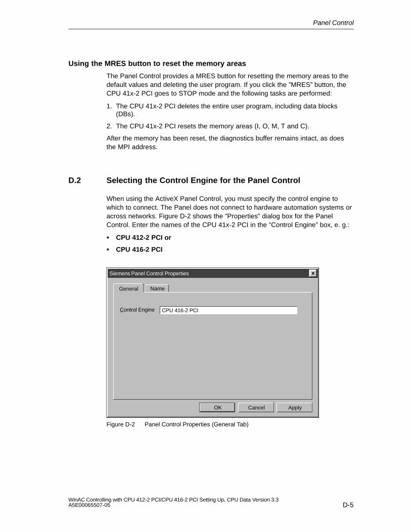
Panel Control
D-5WinAC Controlling with CPU 412-2 PCI/CPU 416-2 PCI Setting Up, CPU Data Version 3.3A5E00065507-05
Using the MRES button to reset the memory areas
The Panel Control provides a MRES button for resetting the memory areas to thedefault values and deleting the user program. If you click the ”MRES” button, theCPU 41x-2 PCI goes to STOP mode and the following tasks are performed:
1. The CPU 41x-2 PCI deletes the entire user program, including data blocks(DBs).
2. The CPU 41x-2 PCI resets the memory areas (I, O, M, T and C).
After the memory has been reset, the diagnostics buffer remains intact, as doesthe MPI address.
D.2 Selecting the Control Engine for the Panel Control
When using the ActiveX Panel Control, you must specify the control engine towhich to connect. The Panel does not connect to hardware automation systems oracross networks. Figure D-2 shows the ”Properties” dialog box for the PanelControl. Enter the names of the CPU 41x-2 PCI in the ”Control Engine” box, e. g.:
CPU 412-2 PCI or
CPU 416-2 PCI
Siemens Panel Control Properties
OK Cancel Apply
General
CPU 416-2 PCIControl Engine
Name
Figure D-2 Panel Control Properties (General Tab)
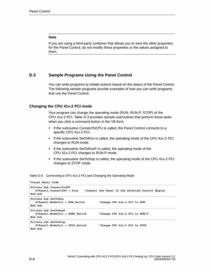
Panel Control
D-6WinAC Controlling with CPU 412-2 PCI/CPU 416-2 PCI Setting Up, CPU Data Version 3.3
A5E00065507-05
Note
If you are using a third-party container that allows you to view the other propertiesfor the Panel Control, do not modify these properties or the values assigned tothem.
D.3 Sample Programs Using the Panel Control
You can write programs to initiate actions based on the status of the Panel Control.The following sample programs provide examples of how you can write programsthat use the Panel Control.
Changing the CPU 41x-2 PCI mode
Your program can change the operating mode (RUN, RUN-P, STOP) of theCPU 41x-2 PCI. Table D-3 provides sample subroutines that perform these taskswhen you click a command button in the VB form.
If the subroutine ConnectToCPU is called, the Panel Control connects to aspecific CPU 41x-2 PCI.
If the subroutine SetToRun is called, the operating mode of the CPU 41x-2 PCIchanges to RUN mode.
If the subroutine SetToRunP is called, the operating mode of theCPU 41x-2 PCI changes to RUN-P mode.
If the subroutine SetToStop is called, the operating mode of the CPU 41x-2 PCIchanges to STOP mode.
Table D-3 Connecting a CPU 41x-2 PCI and Changing the Operating Mode
Visual Basic Code
Private Sub ConnectToCPUS7Panel1.ConnectCPU = True ’Connect the Panel to the Selected Control Engine
End Sub
Private Sub SetToRunS7Panel1.ModeCtrl = RUN_Switch ’Change CPU 41x-2 PCI to RUN
End Sub
Private Sub SetToRunPS7Panel1.ModeCtrl = RUNP_Switch ’Change CPU 41x-2 PCI to RUN–P
End Sub
Private Sub SetToStopS7Panel1.ModeCtrl = STOP_Switch ’Change CPU 41x-2 PCI to STOP
End Sub
Panel Control
D-7WinAC Controlling with CPU 412-2 PCI/CPU 416-2 PCI Setting Up, CPU Data Version 3.3A5E00065507-05
Configuring the security state of the Panel Control
You can design a custom application that uses the Panel Control, but allows thesecurity for the application to determine whether a user can operate the PanelControl. Since your application will have its own password or other securitychecking, you do not require any additional security checking to be performed bythe Panel Control.
The sample subroutines listed in Table D-4 provide sample code for accomplishingthe following tasks:
To bypass the security provided by the Panel Control, you set the SecurityStateproperty of the Panel Control to App_Does_Security. The Panel Control nowrelies on the application to determine whether the user has permission to makechanges in the CPU 41x-2 PCI.
In this example, the SecurityState property is set to this value when the form forthe application loads.
To ensure that a user must have permission from the application beforeallowing any changes to be made with the Panel Control, you set the SwitchOKproperty of the Panel Control to False. The button on the Panel Control will nowrespond to user requests only if the application changes the state of theSwitchOK property.
In this example, the SwitchOK property is set to False when the form for theapplication loads.
To enable the user to make changes to the CPU 41x-2 PCI with the PanelControl, your application sets the SwitchOK property of the Panel Control toTrue.
When the PerformSecurityCheck subroutine determines that the user haspermission to make changes with the Panel Control, the subroutine sets theSwitchOK property of the Panel Control to True. Until the SwitchOK property isset to True, the Panel Control does not make the change requested by the user.
Using this sample code, any time that a user requests the Panel Control to performsome task, the Panel Control determines whether the user has been givenpermission by the application to make the requested change. For example, when auser clicks on the “RUN” button of the Panel Control to change the CPU 41x-2 PCIfrom STOP mode to Run mode, the Panel Control checks the state of theSwitchOK property before changing the operating mode of the CPU 41x-2 PCI.
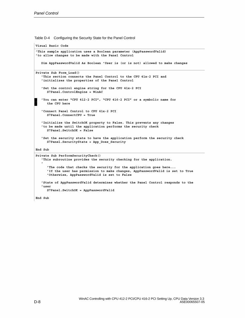
Panel Control
D-8WinAC Controlling with CPU 412-2 PCI/CPU 416-2 PCI Setting Up, CPU Data Version 3.3
A5E00065507-05
Table D-4 Configuring the Security State for the Panel Control
Visual Basic Code
’This sample application uses a Boolean parameter (AppPasswordValid) ’to allow changes to be made with the Panel Control
Dim AppPasswordValid As Boolean ’User is (or is not) allowed to make changes
Private Sub Form_Load()’This section connects the Panel Control to the CPU 41x-2 PCI and’initializes the properties of the Panel Control
’Set the control engine string for the CPU 41x-2 PCIS7Panel.ControlEngine = WinAC
’You can enter “CPU 412-2 PCI”, “CPU 416-2 PCI” or a symbolic name for the CPU here
’Connect Panel Control to CPU 41x-2 PCIS7Panel.ConnectCPU = True
’Initialize the SwitchOK property to False. This prevents any changes ’to be made until the application performs the security check
S7Panel.SwitchOK = False
’Set the security state to have the application perform the security checkS7Panel.SecurityState = App_Does_Security
End Sub
Private Sub PerformSecurityCheck()’This subroutine provides the security checking for the application. ’
’The code that checks the security for the application goes here...’If the user has permission to make changes, AppPasswordValid is set to True’Otherwise, AppPasswordValid is set to False
’State of AppPasswordValid determines whether the Panel Control responds to the ’user
S7Panel.SwitchOK = AppPasswordValid
End Sub
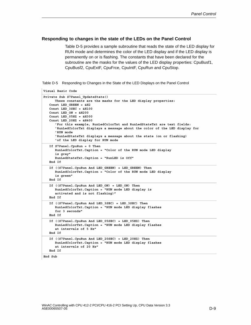
Panel Control
D-9WinAC Controlling with CPU 412-2 PCI/CPU 416-2 PCI Setting Up, CPU Data Version 3.3A5E00065507-05
Responding to changes in the state of the LEDs on the Panel Control
Table D-5 provides a sample subroutine that reads the state of the LED display forRUN mode and determines the color of the LED display and if the LED display ispermanently on or is flashing. The constants that have been declared for thesubroutine are the masks for the values of the LED display properties: CpuBusf1,CpuBusf2, CpuExtF, CpuFrce, CpuIntF, CpuRun and CpuStop.
Table D-5 Responding to Changes in the State of the LED Displays on the Panel Control
Visual Basic Code
Private Sub S7Panel_UpdateState()These constants are the masks for the LED display properties:
Const LED_GREEN = &H2Const LED_3SEC = &H100Const LED_ON = &H200Const LED_05HZ = &H300Const LED_20HZ = &H400
’For this example, RunLedColorTxt and RunLedStateTxt are text fields:’RunLedColorTxt displays a message about the color of the LED display for ’RUN mode’RunLedStateTxt displays a message about the state (on or flashing)’of the LED display for RUN mode
If S7Panel.CpuRun = 0 ThenRunLedColorTxt.Caption = “Color of the RUN mode LED displayis gray”RunLedStateTxt.Caption = “RunLED is Off”
End If
If ((S7Panel.CpuRun And LED_GREEN) = LED_GREEN) ThenRunLedColorTxt.Caption = “Color of the RUN mode LED displayis green”
End If
If ((S7Panel.CpuRun And LED_ON) = LED_ON) ThenRunLedColorTxt.Caption = “RUN mode LED display isactivated and is not flashing)”
End If
If ((S7Panel.CpuRun And LED_3SEC) = LED_3SEC) ThenRunLedColorTxt.Caption = “RUN mode LED display flashesfor 3 seconds”
End If
If ((S7Panel.CpuRun And LED_05SEC) = LED_05HZ) ThenRunLedColorTxt.Caption = “RUN mode LED display flashesat intervals of 5 Hz”
End If
If ((S7Panel.CpuRun And LED_20SEC) = LED_20HZ) ThenRunLedColorTxt.Caption = “RUN mode LED display flashesat intervals of 20 Hz”
End If
End Sub
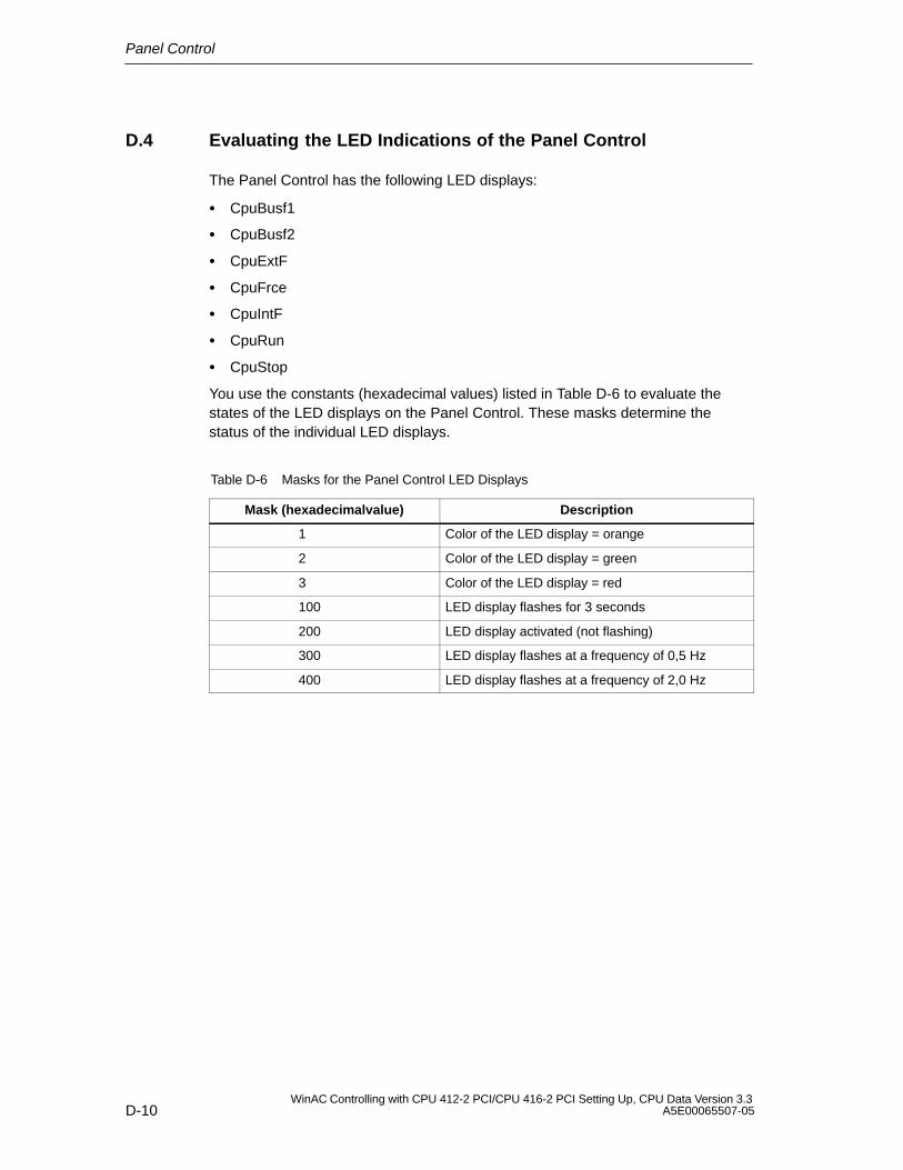
Panel Control
D-10WinAC Controlling with CPU 412-2 PCI/CPU 416-2 PCI Setting Up, CPU Data Version 3.3
A5E00065507-05
D.4 Evaluating the LED Indications of the Panel Control
The Panel Control has the following LED displays:
CpuBusf1
CpuBusf2
CpuExtF
CpuFrce
CpuIntF
CpuRun
CpuStop
You use the constants (hexadecimal values) listed in Table D-6 to evaluate thestates of the LED displays on the Panel Control. These masks determine thestatus of the individual LED displays.
Table D-6 Masks for the Panel Control LED Displays
Mask (hexadecimalvalue) Description
1 Color of the LED display = orange
2 Color of the LED display = green
3 Color of the LED display = red
100 LED display flashes for 3 seconds
200 LED display activated (not flashing)
300 LED display flashes at a frequency of 0,5 Hz
400 LED display flashes at a frequency of 2,0 Hz
Panel Control
D-11WinAC Controlling with CPU 412-2 PCI/CPU 416-2 PCI Setting Up, CPU Data Version 3.3A5E00065507-05
D.5 Properties and Methods of the Panel Control
ActiveFilePath property
This read-only property provides the pathname to the control engine(CPU 41x-2 PCI).
Syntax:
[value =] object.ActiveFilePath
The ActiveFilePath property has these parts:
Part Description
object The expression ”object” refers to the Panel Control.
value A string expression that evaluates to the name of thecontroller.
AutoStart property
This property allows you to select the “autostart” feature for WinLC. This propertyis valid only for WinLC. For information about the autostart feature, refer to theWinLC documentation.
Syntax:
object.AutoStart [= value]
The AutoStart property has these parts:
Part Description
object The expression ”object” refers to the Panel Control.
value A Boolean expression that specifies whether the autostartfeature is enabled for the object.
The settings for the value are:
Setting Description
True The autostart feature of WinLC is enabled.
False (default) The autostart feature of WinLC is disabled.
CheckPW property
This property determines whether the password entered was correct. If thepassword entered matches the password stored in the control engine, the controlexecutes the requested action.
Panel Control
D-12WinAC Controlling with CPU 412-2 PCI/CPU 416-2 PCI Setting Up, CPU Data Version 3.3
A5E00065507-05
Syntax:
object.CheckPW [= value]
The CheckPW property has these parts:
Part Description
object The expression ”object” refers to the Panel Control.
value An integer that determines whether the object performsthe requested action.
The settings for the value are:
Setting Description
0 – Check_Wait (default) The control engine is verifying the password.
1 – Check_Good The password entered was correct and the action isallowed.
2 – Check_Bad The password entered was incorrect and the action is notallowed.
ConnectCPU property
This property establishes a connection to the S7 controller cancels this connection(CPU 41x-2 PCI).
Syntax:
object.ConnectCPU [= value]
The ConnectCPU method has these parts:
Part Description
object The expression ”object” refers to the Panel Control.
value A Boolean expression that specifies whether the objectestablishes a connection to the S7 control engine.
The settings for the value are:
Setting Description
True The object connects to the S7 controller.
False (default) The object disconnects from the S7 controller.
ControlEngine property
This property stores the pathname or identification of the control engine connectedto the control.
Panel Control
D-13WinAC Controlling with CPU 412-2 PCI/CPU 416-2 PCI Setting Up, CPU Data Version 3.3A5E00065507-05
Syntax:
object.ControlEngine [= value]
The ControlEngine property has these parts:
Part Description
object The expression ”object” refers to the Panel Control.
value A string that specifies the pathname or identification of thecontrol engine to be accessed by the object.
CpuBusf1, CpuBusf2 properties
This read-only property displays the state of the communication indicators (BUSF1and BUSF2) on the control. BUSF1 indicates the state of the distributed I/O for thecontrol engine. If a second network is supported by the control engine, BUSF2shows the status of the second network.
Syntax:
[value =] object.CpuBusf1 [value =] object.CpuBusf2
The CpuBusf1 and CpuBusf2 properties have these parts:
Part Description
object The expression ”object” refers to the Panel Control.
value An integer expression that specifies the status of the busfault (BUSF1 or BUSF2) on the object.
Settings for the value are shown in Table D-6.
CpuExtF property
This read-only property shows the state of the External Error display on thecontrol. External errors do not occur in the CPU of the control engine. They arewire breakage of the local inputs and outputs, for example.
Syntax:
[value =] object.CpuExtF
The syntax of the CpuExtF property has these components:
Part Description
object The expression ”object” refers to the Panel Control.
value An integer expression that specifies the status of theEXTF indicator on the object.
Settings for the value are shown in Table D-6.
Panel Control
D-14WinAC Controlling with CPU 412-2 PCI/CPU 416-2 PCI Setting Up, CPU Data Version 3.3
A5E00065507-05
CpuFrce property
This read-only property shows the state of the FRCE indicator on the control. TheFRCE display lights to signal that a user-requested Force function is active. (Usingthe STEP 7 programming software, the user can stipulate that the control engineset or force an input or output to a specific value.)
Syntax:
[value =] object.CpuFrce
The CpuFrce property has these parts:
Part Description
object The expression ”object” refers to the Panel Control.
value An integer expression that specifies the status of theFRCE indicator on the object.
Settings for the value are shown in Table D-6.
CpuIntF property
This read-only property shows the state of the Internal Error display on the control.Internal faults are errors that are detected within the CPU module of the controlengine, such as programming errors that cause the control engine to go to STOPmode.
Syntax:
[value =] object.CpuIntF
The CpuIntF property has these parts:
Part Description
object The expression ”object” refers to the Panel Control.
value An integer expression that specifies the status of the INTFindicator on the object.
Settings for the value are shown in Table D-6.
CpuRun property
This read-only property shows the state of the RUN mode display on the control.
Syntax:
[value =] object.CpuRun
Panel Control
D-15WinAC Controlling with CPU 412-2 PCI/CPU 416-2 PCI Setting Up, CPU Data Version 3.3A5E00065507-05
The CpuRun property has these parts:
Part Description
object The expression ”object” refers to the Panel Control.
value An integer expression that specifies the state of the RUNindicator.
Settings for the value are shown in Table D-6.
CPURunning property
This read-only property indicates that the control engine is still running or inoperation. The control queries the control engine, and if the control engineresponds, the property is set to True.
Syntax:
[value =] object.CpuRunning
The CpuRunning property has these parts:
Part Description
object The expression ”object” refers to the Panel Control.
value A Boolean expression that specifies whether the controlengine is running and able to respond to the control.
The settings for the value are:
Setting Description
True The control engine is running and has responded to thequery by the control
False (default) The control engine is not running or notresponding.
CpuStop value
This read-only property shows the state of the STOP mode indicator on thecontrol.
Syntax:
[value =] object.CpuStop
The CpuStop property has these parts:
Panel Control
D-16WinAC Controlling with CPU 412-2 PCI/CPU 416-2 PCI Setting Up, CPU Data Version 3.3
A5E00065507-05
Part Description
object The expression ”object” refers to the Panel Control.
value An integer expression that specifies the state of the STOPindicator.
Settings for the value are shown in Table D-6.
FirmwareVersion property
This read-only property stores the revision level of the firmware in the controlengine.
Syntax:
[value =] object.FirmwareVersion
The FirmwareVersion property has these parts:
Part Description
object The expression ”object” refers to the Panel Control.
value A string value that describes the revision level of thefirmware for the control engine.
FmrSwitch property
This property restarts the backup battery.
Syntax:
object.FmrSwitch [= value]
The FmrSwitch property has these parts:
Part Description
object The expression ”object” refers to the Panel Control.
value A Boolean expression that causes the control engine torestart the backup battery.
The settings for the value are:
Setting Description
True The control engine performs a battery restart (FMR).
False (default) No action is required.
Panel Control
D-17WinAC Controlling with CPU 412-2 PCI/CPU 416-2 PCI Setting Up, CPU Data Version 3.3A5E00065507-05
HardwareVersion property
This read-only property stores the version (revision level) of the control enginehardware.
Syntax:
[value =] object.HardwareVersion
The HardwareVersion property has these parts:
Part Description
object The expression ”object” refers to the Panel Control.
value A string value that describes the hardware version for thecontrol engine.
mlfb property
This read only property stores the CPU 41x-2 PCI order number.
Syntax:
[value =] object.mlfb
The mlfb property has these parts:
Part Description
object The expression ”object” refers to the Panel Control.
value A string value that specifies the order number for thecontrol engine.
ModeCtrl property
This property changes the operating mode of the control engine.
Syntax:
object.ModeCtrl [= value]
The ModeCtrl property has these parts:
Part Description
object The expression ”object” refers to the Panel Control.
value An integer that determines the new operating mode for thecontrol engine.
Panel Control
D-18WinAC Controlling with CPU 412-2 PCI/CPU 416-2 PCI Setting Up, CPU Data Version 3.3
A5E00065507-05
The settings for the value are:
Setting Description
0 MRES (memory restart)
1 STOP mode
2 RUN mode
3 RUN-P mode
OnStateChanged method
This method is used internally by the control and must not be modified.
PSBattF property
This read-only property shows the state of the ”Battery Fault” indicator on thecontrol. This property is valid for the control engine. The BATTF indicator lights toalert the user to a battery fault condition.
Syntax:
[value =] object.PSBattF
The PSBattF property has these parts:
Part Description
object The expression ”object” refers to the Panel Control.
value An integer expression that specifies the status of theBATTF indicator on the object.
Settings for the value are shown in Table D-6.
PSOn property
This read-only property shows the state of the power supply (ON) display on thecontrol. The ON display shows the status of the power supply for the controlengine.
Syntax:
[value =] object.PSOn
Part Description
object The expression ”object” refers to the Panel Control.
value An integer expression that specifies the status of the PSindicator on the object.
Panel Control
D-19WinAC Controlling with CPU 412-2 PCI/CPU 416-2 PCI Setting Up, CPU Data Version 3.3A5E00065507-05
Settings for the value are shown in Table D-6.
PwrSwitch property
This property indicates the on/off status of the control engine.
Syntax:
object.PwrSwitch [= value]
The PwrSwitch property has these parts:
Part Description
object The expression ”object” refers to the Panel Control.
value A Boolean expression that specifies whether the controlengine is enabled or disabled.
The settings for the value are:
Setting Description
True The control engine is enabled.
False The control engine is disabled.
ResourceFile property
This read-only property determines the name of the DLL for the language-specificstrings displayed by the control.
Syntax:
object.ResourceFile [= value]
The ResourceFile property has these parts:
Part Description
object The expression ”object” refers to the Panel Control.
value A string that determines the name for thelanguage-specific DLL.
ResourcePath property
This read-only property contains the pathname of the language-specific DLLselected for the control.
Syntax:
object.ResourcePath [= value]
Panel Control
D-20WinAC Controlling with CPU 412-2 PCI/CPU 416-2 PCI Setting Up, CPU Data Version 3.3
A5E00065507-05
The ResourcePath property has these parts:
Part Description
object The expression ”object” refers to the Panel Control.
value A string that determines the pathname for thelanguage-specific DLL.
SecurityState property
This property determines the level of security in effect for the control:
Panel Control handles security checking.
Disables the security checking by the control. Your application performs all ofthe security. (See also the SwitchOK property.)
Syntax:
object.SecurityState [= value]
The SecurityState property has these parts:
Part Description
object The expression ”object” refers to the Panel Control.
value An integer that determines the level of security for theobject.
The settings for the value are:
Setting Description
0 Panel Control provides security checks.
1 The security checking performed by the control isdisabled. Your application performs all of the security. (Seealso the SwitchOK property.)
SetPassword property
If set to True, this property executes the “Set Password” function for changing thepassword in the control engine.
Syntax:
object.SetPassword [= value]
Panel Control
D-21WinAC Controlling with CPU 412-2 PCI/CPU 416-2 PCI Setting Up, CPU Data Version 3.3A5E00065507-05
The SetPassword property has these parts:
Part Description
object The expression ”object” refers to the Panel Control.
value A Boolean expression that determines whether to call the“Set Password” function.
The settings for the value are:
Setting Description
True The control calls the “Set Password” function for changingthe password in the control engine.
False (default) No action.
ShowErrorBoxes property
This property specifies whether to display the default error boxes when there is auser-generated error. Every time an error occurs, an Error event will be generated.If the ShowErrorBoxes property is enabled, a standard error message box will bedisplayed.
All errors on connections are reported by the Connection Error event.
Syntax:
object.ShowErrorBoxes [= value]
The ShowErrorBoxes property has these parts:
Part Description
object The expression ”object” refers to the Panel Control.
value A Boolean expression that specifies whether the controldisplays error boxes.
The settings for the value are:
Setting Description
True (default) The control shows standard error boxes.
False The error boxes are hidden.
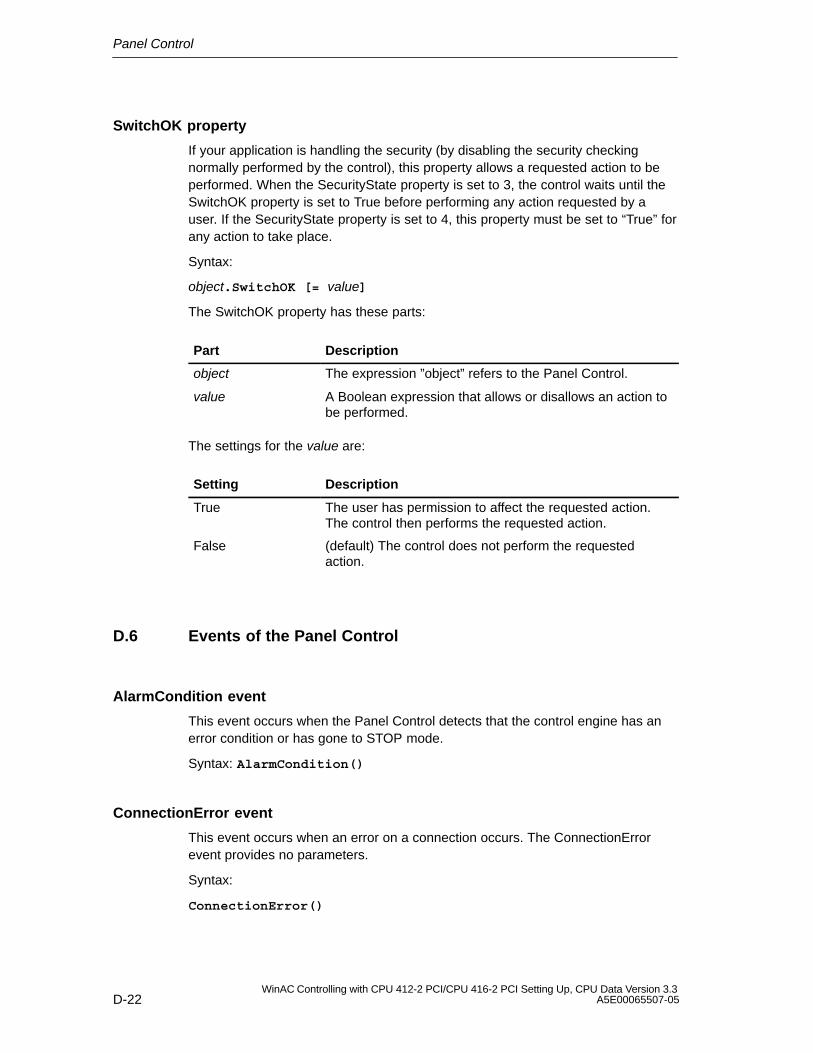
Panel Control
D-22WinAC Controlling with CPU 412-2 PCI/CPU 416-2 PCI Setting Up, CPU Data Version 3.3
A5E00065507-05
SwitchOK property
If your application is handling the security (by disabling the security checkingnormally performed by the control), this property allows a requested action to beperformed. When the SecurityState property is set to 3, the control waits until theSwitchOK property is set to True before performing any action requested by auser. If the SecurityState property is set to 4, this property must be set to “True” forany action to take place.
Syntax:
object.SwitchOK [= value]
The SwitchOK property has these parts:
Part Description
object The expression ”object” refers to the Panel Control.
value A Boolean expression that allows or disallows an action tobe performed.
The settings for the value are:
Setting Description
True The user has permission to affect the requested action.The control then performs the requested action.
False (default) The control does not perform the requestedaction.
D.6 Events of the Panel Control
AlarmCondition event
This event occurs when the Panel Control detects that the control engine has anerror condition or has gone to STOP mode.
Syntax: AlarmCondition()
ConnectionError event
This event occurs when an error on a connection occurs. The ConnectionErrorevent provides no parameters.
Syntax:
ConnectionError()
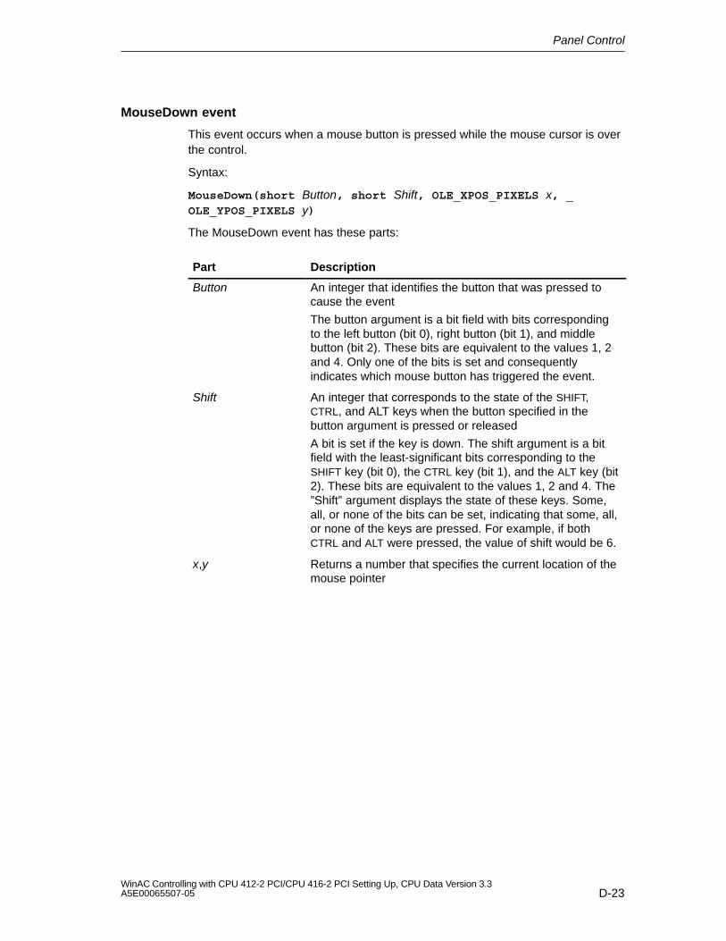
Panel Control
D-23WinAC Controlling with CPU 412-2 PCI/CPU 416-2 PCI Setting Up, CPU Data Version 3.3A5E00065507-05
MouseDown event
This event occurs when a mouse button is pressed while the mouse cursor is overthe control.
Syntax:
MouseDown(short Button, short Shift, OLE_XPOS_PIXELS x, _OLE_YPOS_PIXELS y)
The MouseDown event has these parts:
Part Description
Button An integer that identifies the button that was pressed tocause the event
The button argument is a bit field with bits correspondingto the left button (bit 0), right button (bit 1), and middlebutton (bit 2). These bits are equivalent to the values 1, 2and 4. Only one of the bits is set and consequentlyindicates which mouse button has triggered the event.
Shift An integer that corresponds to the state of the SHIFT,CTRL, and ALT keys when the button specified in thebutton argument is pressed or released
A bit is set if the key is down. The shift argument is a bitfield with the least-significant bits corresponding to theSHIFT key (bit 0), the CTRL key (bit 1), and the ALT key (bit2). These bits are equivalent to the values 1, 2 and 4. The”Shift” argument displays the state of these keys. Some,all, or none of the bits can be set, indicating that some, all,or none of the keys are pressed. For example, if bothCTRL and ALT were pressed, the value of shift would be 6.
x,y Returns a number that specifies the current location of themouse pointer
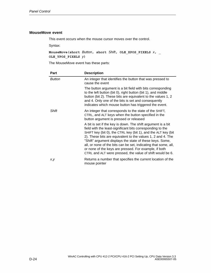
Panel Control
D-24WinAC Controlling with CPU 412-2 PCI/CPU 416-2 PCI Setting Up, CPU Data Version 3.3
A5E00065507-05
MouseMove event
This event occurs when the mouse cursor moves over the control.
Syntax:
MouseMove(short Button, short Shift, OLE_XPOS_PIXELS x, _OLE_YPOS_PIXELS y)
The MouseMove event has these parts:
Part Description
Button An integer that identifies the button that was pressed tocause the event
The button argument is a bit field with bits correspondingto the left button (bit 0), right button (bit 1), and middlebutton (bit 2). These bits are equivalent to the values 1, 2and 4. Only one of the bits is set and consequentlyindicates which mouse button has triggered the event.
Shift An integer that corresponds to the state of the SHIFT,CTRL, and ALT keys when the button specified in thebutton argument is pressed or released
A bit is set if the key is down. The shift argument is a bitfield with the least-significant bits corresponding to theSHIFT key (bit 0), the CTRL key (bit 1), and the ALT key (bit2). These bits are equivalent to the values 1, 2 and 4. The”Shift” argument displays the state of these keys. Some,all, or none of the bits can be set, indicating that some, all,or none of the keys are pressed. For example, if bothCTRL and ALT were pressed, the value of shift would be 6.
x,y Returns a number that specifies the current location of themouse pointer
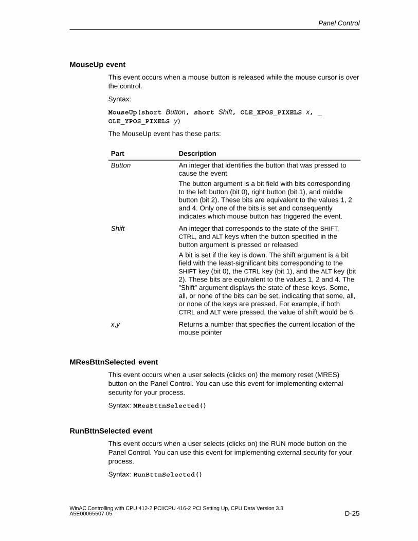
Panel Control
D-25WinAC Controlling with CPU 412-2 PCI/CPU 416-2 PCI Setting Up, CPU Data Version 3.3A5E00065507-05
MouseUp event
This event occurs when a mouse button is released while the mouse cursor is overthe control.
Syntax:
MouseUp(short Button, short Shift, OLE_XPOS_PIXELS x, _OLE_YPOS_PIXELS y)
The MouseUp event has these parts:
Part Description
Button An integer that identifies the button that was pressed tocause the event
The button argument is a bit field with bits correspondingto the left button (bit 0), right button (bit 1), and middlebutton (bit 2). These bits are equivalent to the values 1, 2and 4. Only one of the bits is set and consequentlyindicates which mouse button has triggered the event.
Shift An integer that corresponds to the state of the SHIFT,CTRL, and ALT keys when the button specified in thebutton argument is pressed or released
A bit is set if the key is down. The shift argument is a bitfield with the least-significant bits corresponding to theSHIFT key (bit 0), the CTRL key (bit 1), and the ALT key (bit2). These bits are equivalent to the values 1, 2 and 4. The”Shift” argument displays the state of these keys. Some,all, or none of the bits can be set, indicating that some, all,or none of the keys are pressed. For example, if bothCTRL and ALT were pressed, the value of shift would be 6.
x,y Returns a number that specifies the current location of themouse pointer
MResBttnSelected event
This event occurs when a user selects (clicks on) the memory reset (MRES)button on the Panel Control. You can use this event for implementing externalsecurity for your process.
Syntax: MResBttnSelected()
RunBttnSelected event
This event occurs when a user selects (clicks on) the RUN mode button on thePanel Control. You can use this event for implementing external security for yourprocess.
Syntax: RunBttnSelected()
Panel Control
D-26WinAC Controlling with CPU 412-2 PCI/CPU 416-2 PCI Setting Up, CPU Data Version 3.3
A5E00065507-05
RunPBttnSelected event
This event occurs when a user selects (clicks on) the RUN-P mode button on thePanel Control. You can use this event for implementing external security for yourprocess.
Syntax: RunPBttnSelected()
StopBttnSelected event
This event occurs when a user selects (clicks on) the STOP mode button on thePanel Control. You can use this event for implementing external security for yourprocess.
Syntax: StopBttnSelected()
UpdateState event
This event occurs when the Panel Control detects a change in the status of thecontrol engine.
Syntax: UpdateState()
E-1WinAC Controlling with CPU 412-2 PCI/CPU 416-2 PCI Setting Up, CPU Data Version 3.3A5E00065507-05
Spare Parts and Accessories – OrderNumbers
You will find further order numbers in the ST 70 Catalog.
Spare Parts/Accessories Order No.
CPU 412-2 PCI 6ES7 612-2QH00-0AB4
CPU 416-2 PCI 6ES7 616-2QL00-0AB4
PS extension board 6ES7 678-1RA00-0XB0
Lithium battery, 3.6 V 6ES7 971-2BA00-0AA0
Bus connector without a programming device socket 6ES7 972-0BA40-0XA0/6GK1 500-0EA02
Bus connector with a programming device socket 6ES7 972-0BB40-0XA0
Y-cable for 12 V voltage supply from the PC powersupply unit to PS
C79459-A1490-B5
Connector for connection of 24 V DC to PS extensionboard with 1.5 m cable
Fa. ODUSteckverbindungssystemeconnector Mini Snap seriesS11B0C-L03MPH0-7000
Battery holder C79459-A1490-D11
E

Spare Parts and Accessories – Order Numbers
E-2WinAC Controlling with CPU 412-2 PCI/CPU 416-2 PCI Setting Up, CPU Data Version 3.3
A5E00065507-05
F-1WinAC Controlling with CPU 412-2 PCI/CPU 416-2 PCI Setting Up, CPU Data Version 3.3A5E00065507-05
Guidelines for Handling ElectrostaticSensitive Devices (ESD)
Introduction
In this appendix, we explain
what is meant by “electrostatic sensitive devices”
the precautions you must observe when handling and working with electrostaticsensitive devices.
In this chapter
This chapter contains the following sections on electrostatic sensitive devices:
Section Contents Page
F.1 What are ESDs? F-2
F.2 Electrostatic Charging of Persons F-3
F.3 General Protective Measures against Electrostatic DischargeDamage
F-4
F
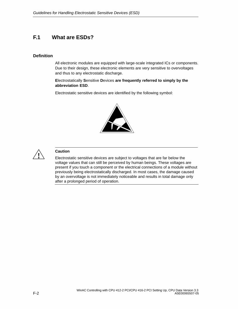
Guidelines for Handling Electrostatic Sensitive Devices (ESD)
F-2WinAC Controlling with CPU 412-2 PCI/CPU 416-2 PCI Setting Up, CPU Data Version 3.3
A5E00065507-05
F.1 What are ESDs?
Definition
All electronic modules are equipped with large-scale integrated ICs or components.Due to their design, these electronic elements are very sensitive to overvoltagesand thus to any electrostatic discharge.
Electrostatically Sensitive Devices are frequently referred to simply by theabbreviation ESD.
Electrostatic sensitive devices are identified by the following symbol:
!Caution
Electrostatic sensitive devices are subject to voltages that are far below thevoltage values that can still be perceived by human beings. These voltages arepresent if you touch a component or the electrical connections of a module withoutpreviously being electrostatically discharged. In most cases, the damage causedby an overvoltage is not immediately noticeable and results in total damage onlyafter a prolonged period of operation.

Guidelines for Handling Electrostatic Sensitive Devices (ESD)
F-3WinAC Controlling with CPU 412-2 PCI/CPU 416-2 PCI Setting Up, CPU Data Version 3.3A5E00065507-05
F.2 Electrostatic Charging of Persons
Charging
Every person with a non-conductive connection to the electrical potential of his/hersurroundings can be charged electrostatically.
Figure F-1 shows you the maximum values for electrostatic voltages to which aperson can be exposed by coming into contact with the materials indicated in thefigure. These values conform to the specifications of IEC 801-2.
Voltage in kV
123456789
10111213141516
(kV)
5 10 20 30 40 50 60 70 80 90 100 Relative airhumidityin %
1
3
1 Synthetic material
2 Wool
3 Antistatic material,for example, woodor concrete
2
Figure F-1 Electrostatic Voltages which Can Build Up on a Person
Guidelines for Handling Electrostatic Sensitive Devices (ESD)
F-4WinAC Controlling with CPU 412-2 PCI/CPU 416-2 PCI Setting Up, CPU Data Version 3.3
A5E00065507-05
F.3 General Protective Measures Against ElectrostaticDischarge Damage
Ensure sufficient grounding
Make sure that the personnel, working surfaces and packaging are sufficientlygrounded when handling electrostatic sensitive devices. You thus avoidelectrostatic charging.
Before starting work on the PC, for example, touch the housing of the PC.
Avoid direct contact
You should touch electrostatic sensitive devices only if it is unavoidable(for example, during maintenance work). Hold modules without touching the pins ofcomponents or printed conductors. In this way, the discharged energy cannotaffect the sensitive devices.
If you have to carry out measurements on a module, you must discharge yourbody before you start the measurement by touching grounded metallic parts. Usegrounded measuring devices only.
G-1WinAC Controlling with CPU 412-2 PCI/CPU 416-2 PCI Setting Up, CPU Data Version 3.3A5E00065507-05
List of Abbreviations
Abbrevia-tions
Description
CP Communication processor
CPU Central processing unit
DB Data block
FB Function block
FC Function
FOC Fiber-optic cable
FM Function module
GD Global data communication
LAD Ladder logic (programming language representation in STEP 7)
IM Interface module
M Electrical bonding
MPI Multipoint interface
OB Organization block
OP Operator panel
IP Intelligent I/O
PG Programming device
PII Process image input table
PIQ Process-image output table
PLC Programmable logic controller
PS Power supply
PZF I/O access error
SFB System function block
SFC System function
SM Signal module
STL Statement list (programming language representation in STEP 7)
G

List of Abbreviations
G-2WinAC Controlling with CPU 412-2 PCI/CPU 416-2 PCI Setting Up, CPU Data Version 3.3
A5E00065507-05
Glossary-1WinAC Controlling with CPU 412-2 PCI/CPU 416-2 PCI Setting Up, CPU Data Version 3.3A5E00065507-05
Glossary
B
Backup battery
The backup battery ensures that the user program in the CPU is stored inthe event of a power failure and that defined data areas and memory markers,timers and counters are retentive.
BIOS
Basic Input Output System
BIOS means that part of the software that establishes the connection betweenhardware and the operating system – for example, MS–DOS. This software isstored in an EPROM.
Important components are, for example, loaders for the operating system, the(hardware) Setup for establishing the hardware configuration and for setting thetime.
Bus
A bus is a communication medium connecting several nodes. Data transmissioncan be serial or parallel across electrical conductors or fiber-optic cables.
C
Chassis ground
The chassis ground is the sum of all the interconnected inactive parts of aresource which cannot assume a hazardous contact voltage even in the event of afault.
Clock
Timers
Glossary
Glossary-2WinAC Controlling with CPU 412-2 PCI/CPU 416-2 PCI Setting Up, CPU Data Version 3.3
A5E00065507-05
Cold restart
Complete restart of the programmable control system and its application after allthe dynamic data (variables of the I/O image, internal registers, timers, counters,etc. and associated program parts) have been reset to a predefined value. A coldrestart can be initiated automatically (for example, following a power failure, a lossof information in dynamic memory sections, etc.) or manually.
Communication processor
Communication processors are modules for point-to-point and bus links.
Configuration
Assignment of modules to racks/slots and (for example, for signal modules)addresses.
Configuring
By configuring we mean the grouping of individual modules to form an automationsystem.
Counter
Counters are component parts of the CPU system memory. The contents of the”counter cells” can be modified by STEP 7 instructions (for example, countup/count down).
CPU
A central processing unit is the main processing unit of the automation system witha processor, arithmetic unit, memory, operating system and interface for theprogramming device.
Glossary
Glossary-3WinAC Controlling with CPU 412-2 PCI/CPU 416-2 PCI Setting Up, CPU Data Version 3.3A5E00065507-05
D
Data block
Data blocks (DB) are parts of the user program that contain the program data.There are global data blocks, which can be accessed by all logic blocks, and thereare instance data blocks, which are assigned to a specific FB call.
Data, static
Static data are data which can be used only within a function block. The data issaved in an instance data block belonging to the function block. The data stored inthe instance data block is retained until the next time the function block is called.
Data, temporary
Temporary data are local data of a block which are stored in the L stack duringexecution of a block and which are no longer available after this block has beenexecuted.
Default setting
The default setting is a useful basic setting which is always used when no othervalue is specified (assigned).
E
Electromagnetic compatibility
By electromagnetic compatibility we mean the ability of an electrically operatedresource to operate in a specified environment without influencing that environmentin an unauthorized manner.
Equidistance
Equidistance is a property of PROFIBUS-DP which ensures bus cycles of equallength. “Bus cycles of equal length” means that the DP master always begins theDP bus cycle after the same period of time. From the viewpoint of the connectedDP slaves, this means that they similarly receive their data from the DP master inexactly equal intervals of time.
Glossary
Glossary-4WinAC Controlling with CPU 412-2 PCI/CPU 416-2 PCI Setting Up, CPU Data Version 3.3
A5E00065507-05
Equipotential bonding
Electrical connection (equipotential bonding conductor) which gives the bodies ofelectrical equipment and external conducting bodies the same or approximately thesame potential, in order to prevent interference or dangerous voltages from beinggenerated between these bodies.
Error handling using OB
If the operating system detects a specific error (for example,an access error withSTEP 7), it calls the organization block (error OB) which is provided for this eventand which specifies the subsequent behavior of the CPU.
Error indication
The error indication is one of the possible responses of the operating system to a runtime error. The other possible reactions are: error reaction in the userprogram, STOP mode of the CPU.
Error reaction
Reaction to a runtime error. The operating system can respond in the followingways: conversion of the programmable controller to the STOP mode, call of anorganization block in which the user can program a response or display of theerror.
F
Flash EPROM
FEPROMs are the same as electrically erasable EEPROMS in that they can retaindata in the event of a power failure, but they can be erased much more quickly(FEPROM = Flash Erasable Programmable Read Only Memory). They are usedon memory cards.
Function
A function (FC) in accordance with IEC 1131-3 a logic block without staticdata. A function offers the possibility of passing on parameters in the userprogram. In this way, functions are suitable for programming frequently recurringcomplex functions such as calculations.
Glossary
Glossary-5WinAC Controlling with CPU 412-2 PCI/CPU 416-2 PCI Setting Up, CPU Data Version 3.3A5E00065507-05
Function block
A function block (FB) in accordance with IEC 1131-3 is a logic block with static data. An FB allows parameters to be passed in the user program. Functionblocks are therefore suitable for programming complex functions, e.g. closed-loopcontrols, mode selections, which are repeated frequently.
G
Global data communication
Shared data communication is a procedure used to transfer shared data betweenCPUs (without CFBs).
Ground
The conducting earth whose electric potential can be set equal to zero at any point.
In the vicinity of grounding electrodes, the earth can have a potential different tozero. The term “reference ground” is frequently used to describe thesecircumstances.
Ground, to
To ground means to connect an electrically conducting component to the groundingelectrode (one or more conducting components which have a very good contactwith the earth) across a grounding system.
H
Hardware
Hardware is the name given to the complete physical and technical equipment ofan automation system.
Glossary
Glossary-6WinAC Controlling with CPU 412-2 PCI/CPU 416-2 PCI Setting Up, CPU Data Version 3.3
A5E00065507-05
I
Interface, multipoint
MPI
Internetwork traffic
Internetwork communication is characterized by the fact that the PROFIBUS-DPnodes ”listen in” to find out which data a DP slave is sending back to its DP master.Using this function the eavesdropper (receiver) can directly access changes in theinput data of other DP slaves.
Interrupt
Interrupt is the name given to the interruption of program scanning in the processorby an externally queued event – for example, timer expired, data request, etc.
ISA bus
Abbreviation for “Industry Standard Architecture”.
L
Load memory
The load memory is part of the CPU. It contains the objects generated by theprogramming device. It is implemented either as a plug-in memory card or apermanently integrated memory.
Local data
Data, temporary
Logic block
A logic block in SIMATIC S7 is a block which contains a section of the STEP 7user program (as opposed to a data block, which only contains data).
Glossary
Glossary-7WinAC Controlling with CPU 412-2 PCI/CPU 416-2 PCI Setting Up, CPU Data Version 3.3A5E00065507-05
M
Memory card
Memory cards are memory media in smart card format for CPUs and CPs. Theyare implemented as RAM or Flash EPROM.
Memory markers
Memory markers are part of the system memory of the CPU for storing interimresults. They can be accessed bit by bit, byte by byte, word by word or doubleword by double word.
Mode
The SIMATIC S7 automation systems have the following operating states: STOP, STARTUP, RUN.
Mode switch
The mode switch is used to set the mode you require on the CPU.
Module parameters
Module parameters are values which can be used to control the response of themodule. A distinction is made between static and dynamic module parameters.
MPI
The multipoint interface (MPI) is the programming device interface of SIMATIC S7.It enables the simultaneous operation of several stations (programming devices,text displays, operator panels) on one or more CPUs. Each station is identified bya unique address (MPI address).
Glossary
Glossary-8WinAC Controlling with CPU 412-2 PCI/CPU 416-2 PCI Setting Up, CPU Data Version 3.3
A5E00065507-05
N
Nesting depth
One block can be called from another by means of a block call. Nesting depth isthe number of logic blocks called at the same time.
Network
In terms of communications, a network is the interconnection of several CPUs andother terminal – for example, a programming device – by means of connectingcables. Data exchange is performed between the connected devices.
Node address
The node number represents the ”number” of a CPU or programming device oranother intelligent I/O module when they can communicate with each other acrossa network. The node address is assigned with STEP 7 software.
Non-isolated
On non-isolated input/output modules, there is an electrical connection betweenthe reference potentials of the control and load circuits.
O
Operating system of the CPU
The operating system of the CPU organizes all functions and processes of theCPU which are not associated with a special control task.
Optically isolated
On optically isolated I/O modules, the reference potentials of the control and loadcircuits are galvanically isolated, for example by optocoupler, relay contact ortransformer. Input/output circuits can be connected to a common potential.
Organization block
Organization blocks (OBs) form the interface between the operating system of theS7-400 CPU and the user program. The processing sequence of the user programis defined in the organization blocks.
Glossary
Glossary-9WinAC Controlling with CPU 412-2 PCI/CPU 416-2 PCI Setting Up, CPU Data Version 3.3A5E00065507-05
P
PCI bus
Abbreviation for “peripheral component interconnect bus”. The PCI bus is thestandard bus on the AT-compatible PC.
PLC
Programmable logic controller
Process image
The process image is an integral part of the system memory of the S7-400CPU. The signal states of the input modules are written into the process-imageinput table at the start of the cyclic program. At the end of the cyclic program, thesignal states in the process-image output table are transferred to the outputmodules.
PROFIBUS-DP
Using PROFIBUS-DP, you can set up a distributed I/O system. Digital and analogmodules are transferred by the automation system to the process on site – andover a distance of up to 23 km at that (when using fiber–optic cables).
The digital and analog modules are connected to the automation system via thePROFIBUS-DP fieldbus and addressed in the same way as centralized I/Os.
PROFIBUS-DP conforms to the standard EN 50 170 Volume 2, PROFIBUS.
Programmable logic controller
Programmable logic controllers (PLCs) are electronic controllers whose function issaved as a program in the control unit. The configuration and wiring of the devicetherefore do not depend on the function of the controller. The programmable logiccontroller has the architecture of a computer; it consists of CPU with memory,I/O modules and internal bus system. The I/O and the programming language aredesigned to meet the control engineering requirements.
Programming device
Programming devices are essentially personal computers which are compact,portable and suitable for industrial applications. They are equipped with specialhardware and software for SIMATIC programmable controllers.
Glossary
Glossary-10WinAC Controlling with CPU 412-2 PCI/CPU 416-2 PCI Setting Up, CPU Data Version 3.3
A5E00065507-05
Protective ground
Connection to a common ground, using a protective conductor, for the accessible,conductive parts of the electrical resources which are not normally live but mightbecome live in the event of a fault and which are jointly protected by a protectivedevice.
R
RAM
A RAM (random access memory) is a semiconductor with random access.
Restart
With the S7: when the CPU starts up (for example, after operating the mode switchfrom STOP to RUN or when the mains voltage is ON), either organization blockOB101 (Complete Restart) of organization block OB100 (Restart) is processedinitially, followed by cyclic program processing (OB1). On a restart, theprocess-image input table is read in and the STEP 7 user program is executedstarting with the first command in OB1.
Retentive data
Retentive data are not lost in the event of a line voltage failure if there is a backupbattery.
Runtime error
Errors that occur during running of the user program in the automation system (inother words, not in the process).
S
Scan time
The scan time is the time the CPU requires for processing (OB1) the userprogram.
Shared data
Shared data are data which can be addressed from any logic block (FC, FB, OB).In detail, this refers to memory markers M, inputs I, outputs O, timers, countersand data blocks DB. Absolute or symbolic access can be made to global data.
Glossary
Glossary-11WinAC Controlling with CPU 412-2 PCI/CPU 416-2 PCI Setting Up, CPU Data Version 3.3A5E00065507-05
Startup
STARTUP mode is activated on a transition from STOP mode to RUN mode.Can be initiated by the mode switch or, after POWER UP, by means of an operatorinput on the programming device.
STEP 7
Programming language for programming, configuring and assigning parameters touser programs for SIMATIC S7 PLCs.
System diagnostics
System diagnostics is the term used to describe the detection, evaluation andsignaling of errors which occur within the automation system. Examples of sucherrors are programming errors or failures on modules. System errors can beindicated with LED displays or by STEP 7.
System function
A system function (SFC) is a function which is integrated in the operating systemof the CPU and which can be called in the STEP 7 user program as required.
System function block
A system function block (SFB) is a function block which is integrated in theoperating system of the CPU and which can be called in the STEP 7 user programas required.
System memory
The system memory is integrated on the CPU and implemented as RAM. Thesystem memory includes the operand areas (for example, timers, counters,memory markers, etc.) as well as the data areas (for example, communicationbuffers) required internally by the operating system.
T
Timers
Timers are component parts of the CPU system memory. The contents of thetime cells are automatically updated asynchronously to the user program by theoperating system. The exact function of the time cell ( for example, on-delay) isdefined with STEP 7 instructions and their processing triggered (for example,start).
Glossary
Glossary-12WinAC Controlling with CPU 412-2 PCI/CPU 416-2 PCI Setting Up, CPU Data Version 3.3
A5E00065507-05
Transmission rate
Rate of data transfer (bps)
U
Ungrounded
Without galvanic connection to ground.
User program
The SIMATIC system distinguishes between the operating system of the CPUand user programs. User programs are created with the programming softwareSTEP 7 in the programming languages that are possible (LAD and STL) andstored in logic blocks. Data are stored in data blocks.
V
Version
Products having the same order number are distinguished by their version. Theproduct version is incremented with each upwardly compatible function extension,production-related modification (use of new components) or bug fix.
W
Warm restart
Complete restart following a power failure, with a user-programmed record ofdynamic data and a user program segment defined in the system. A warm restartis identified by setting a status bit or other suitable means which can be read bythe application and indicate that the shutdown of the PLC system caused by thepower failure has been detected in RUN mode.
Index-1WinAC Controlling with CPU 412-2 PCI/CPU 416-2 PCI Setting Up, CPU Data Version 3.3A5E00065507-05
Index
Numbers3COM card, 1-3
AAccess aids, in manual, viAccess error, 5-7Access point configuration, example, time
synchronization, 7-23Access point setting, time synchronization, 7-5Access protection, submenu, 5-21Accessories, E-1Acknowledgement error, 5-6ActiveFilePath property, D-11ActiveX controls, properties, Panel Control,
D-5Additional support, viAddress area
CPU 41x-2 PCI, 6-2reserved, 4-2, 8-11
AlarmCondition event, D-22Applicability, of manual, iiiApplicable documents, how the manual fits in,
vApprovals, iv, A-1Archive
button, 5-17memory card file, 5-13
Area of application, A-2Australia, approval, A-8Autoload, 5-15
submenu ”Customize”, 5-21AutoStart property, D-11
BBackup battery, Glossary-1
connecting, 4-5installation, 2-14order number, E-1passivation layer removal, 4-6supplying, 2-15using, 4-5
BATF, 5-4BATT., 2-15Battery. See backup batteryBattery holder
attaching to PC housing, 2-15for backup battery, 2-14
BF, 1-5BIOS, Glossary-1Bit memories, memory reset, D-4Box PC 620, 1-2Box PC 820, 1-2Bus, Glossary-1Bus cable
installing on bus connectors with ordernumber 6ES7 ... , B-18
length of spur lines, B-13Bus connector
installing bus cable, B-18plugging into module, B-19purpose, B-17removing, B-20setting the terminating resistor, B-19terminating resistor, B-7
Bus segment. See segmentBUSF, 6-4, 6-15BUSF1, 5-4BUSF2, 5-4
CCable length, maximum, B-12Cause of error, 5-7CE, mark, A-2Changes, from previous version of manual, ivChanging the operating mode, D-3
effects on status displays, D-3in STEP 7 and WinCC, D-3in STEP 7 or WinCC, D-3
Chassis ground, Glossary-1Check list, 2-17CheckPW property, D-11Checks before initial power up, 2-17Climatic environmental conditions, A-6Clock failure, 5-6
Index
Index-2WinAC Controlling with CPU 412-2 PCI/CPU 416-2 PCI Setting Up, CPU Data Version 3.3
A5E00065507-05
Cold restart, 5-9, Glossary-2Combi slot, 2-2Commissioning, approach, 4-2commissioning wizard, 7-11Communication error, 5-7Communication processor, Glossary-2Communications, configuration, B-2Complete restart, 5-9
memory reset, D-4status displays, D-5status indicators, D-4
Component configurator, 7-11component configurator, 3-5Components
for MPI network, B-7PROFIBUS-DP network, B-7WinAC Slot 41x, 1-1
ComputingPanel Control, properties, D-5–D-6properties, Panel, D-5–D-6
Configuration, Glossary-2communications, B-2of a PROFIBUS subnet, B-1of an MPI subnet, B-1WinAC Slot 41x, 1-1
Configuration frame. See on Internet athttp://www.ad.siemens.de/simatic-cs
Configuring, Glossary-2ConnectCPU property, D-12ConnectionError event, D-22Control engine
setting in Panel Control, D-5SIMATIC controls, panel, D-1
Control panel, 5-2installation, 5-2LED displays, 5-4
ControlEngine property, D-12Controls
control panel, 5-3menu bar of CPU 41x-2 PCI, 5-16
Controls and display elements, 5-3Counter, Glossary-2Counters, memory reset, D-4CP, G-1CP 1613, 1-3CP 5613, 1-3CPU, G-1, Glossary-2
menu, 5-18CPU 412-2 PCI, 1-2
technical specifications, 8-3CPU 416-2 PCI, 1-2
technical specifications, 8-7
CPU 41x-2 PCIbattery supply, C-2bus interruption, 6-8, 6-20, 6-30compatibilities, 8-11diagnostics addresses for PROFIBUS, 6-7,
6-19differences from previous version, 8-11direct data exchange, 6-29DP address areas, 6-2DP master, 6-3
diagnostics by LEDs, 6-4diagnostics with STEP 7, 6-5
DP services, C-6DP slave, 6-9
diagnostics, 6-14diagnostics by means of LEDs, 6-15diagnostics with STEP 7, 6-16
installation, 2-2interfaces, 1-4operating state changes, 6-8, 6-20, 6-30operation without memory card, C-5order number, E-1parameters, 8-2reset, 4-8resetting, 4-4, 4-8startup response after PC power up, 2-8transfer memory, 6-10
CPU connection, submenu, 5-23CPU Panel Control
button, D-4memory reset, D-4RUN mode
status display, D-5status indicator, D-4
status indicators, restart, D-4STOP mode, status indicator, D-4system error (SF), D-5system fault (SF) indicator, D-4
CpuExtF property, D-13CpuFrce property, D-14CpulntF property, D-14CpuRun property, D-14CpuRunning property, D-15CpuStop value, D-15CSA approval, A-2Customize, submenu, 5-19
Index
Index-3WinAC Controlling with CPU 412-2 PCI/CPU 416-2 PCI Setting Up, CPU Data Version 3.3A5E00065507-05
DData
SIMATIC controls, panel, D-5–D-6static, Glossary-3temporary, Glossary-3
Data block, Glossary-3Data exchange, direct, 6-29DB, G-1Default setting, Glossary-3Defective CD, errors during installation, 3-4Device. See nodeDevice-related diagnostics, CPU 41x-2 PCI as
DP slave, 6-26Diagnostic buffer, 5-7
after memory reset, D-4Diagnostic interrupt, 5-6
CPU 41x-2 PCI as DP slave, 6-27Diagnostics
CPU 41x-2 PCI as DP slave, 6-14device-related, CPU 41x-2 PCI as slave,
6-26Direct Data Exchange, 6-30identifier-related, CPU 41x-2 PCI as DP
slave, 6-25Diagnostics addresses, CPU 41x-2 PCI, 6-7,
6-19Direct Data Exchange, diagnostics, 6-30Direct data exchange, CPU 41x-2 PCI, 6-29Display elements, control panel, 5-3Disturbance variables
pulse-shaped, A-3sinusoidal, A-4
Documentation, on Internet, viDownloading a program to CPU 41x-2 PCI
allowed in RUN-P mode or STOP mode,D-3
not allowed in RUN mode, D-3DP master
CPU 41x-2 PCI, 6-3diagnostics by LEDs, 6-4diagnostics with STEP 7, 6-5
DP slaveCPU 41x-2 PCI, 6-9diagnostics by means of LEDs, 6-15diagnostics with STEP 7, 6-16
DP slave diagnostics, structure, 6-21
EElectromagnetic compatibility, A-3, Glossary-3Entering station names, 7-11entering station names, 3-5Environmental conditions, mechanical, A-6Equidistance, C-6, Glossary-3Equipotential bonding, Glossary-4Error display, 5-5Error handling, using OB, Glossary-4Error indication, Glossary-4Error messages, 5-6Error reaction, Glossary-4ESD guideline, F-1Essential basic skills, iiiEvents
AlarmCondition, D-22ConnectionError, D-22MouseDown, D-23MouseMove, D-24MouseUp, D-25MResBttnSelected, D-25RunBttnSelected, D-25RunPBttnSelected, D-26StopBttnSelected, D-26UpdateState, D-26
ExamplePanel Control programs, D-6time synchronization, 7-10
Exit, button, 5-17External 24 V DC, requirements, 2-12External battery supply, 2-15External voltage supply, requirements, 2-12EXTF, 5-4
Index
Index-4WinAC Controlling with CPU 412-2 PCI/CPU 416-2 PCI Setting Up, CPU Data Version 3.3
A5E00065507-05
FFailure of a station, 5-7Fan, connecting, 2-13FAQ
access to process data, C-15backing up user data without PS extension
board, C-4battery supply, C-2Box PC 620, C-15CPU 41x-2 PCI as DP slave, C-6DP services, C-6equidistance, C-6FLASH card, RAM card, C-5Industrial Ethernet-interface, C-7operation without memory card, C-5PCI, C-14ProTool/Pro, C-8PS extension board and Y-cable, C-4routing, C-7usage without PS extension board, C-3user data backup after power off/on, C-4using the PS extension board, C-2WinCC, C-12
FB, G-1FC, G-1File, menu, 5-17FirmwareVersion property, D-16FLASH card, 10-2
usage, C-5Flash EPROM, Glossary-4FM, G-1FMR, button, 5-19FmrSwitch property, D-16FOC, G-1FRCE, 5-4Function, Glossary-4Function block, Glossary-5
GGB, G-1General, submenu ”Customize”, control panel,
5-19General technical specifications, A-1Getting started, time synchronization, 7-10Ground, Glossary-5Grounded operation, RS 485 repeater, B-23Guide, through manual, viGuideline, ESD, F-1Guidelines, MRES (memory reset), D-2
HHardware, Glossary-5
configuration, 4-1HardwareVersion property, D-17Help, menu, 5-23Highest MPI address, B-4
II/O access error, 8-11
See also access errorIdentifier–related diagnostics, CPU 41x-2 PCI
as DP slave, 6-25IM, G-1Index, 3-4
-component configurator , 3-4component configurator, 7-11
Industrial Ethernet, connection, B-1Industrial Ethernet interface, S7 driver, C-7Installation
control panel, 5-2CPU 41x-2 PCI, 2-2errors during installation, 3-4PS extension board, 2-2requirements, 2-2, 3-1WinAC Slot 41x, 3-1
Insufficient memory, errors during installation,3-4
InterfaceCPU interfaces, 1-4multipoint, Glossary-6PS extension board, 1-6
Interface error, 5-6Interface parameter assignment, time
synchronization, 7-6Internetwork communication, Glossary-6
See also direct data exchangeInterrupt, Glossary-6Interrupts, CPU 41x-2 PCI as DP slave, 6-28INTF, 5-4IP, G-1ISA bus, Glossary-6
LLAD, G-1Language, submenu ”Customize”, 5-20LED displays, control panel, 5-4LEDs, CPU 41x-2 PCI, 1-5
Index
Index-5WinAC Controlling with CPU 412-2 PCI/CPU 416-2 PCI Setting Up, CPU Data Version 3.3A5E00065507-05
Lithium battery. See backup batteryLoad memory, 5-11, Glossary-6
structure, 5-12Loading a program from a controller, allowed in
RUN-P or STOP mode, D-3Loading a program from CPU 41x-2 PCI, not
allowed in RUN mode, D-3Loading a program from the 41x-2 PCI,
allowed in RUN-P or STOP operatingmode, D-3
Local data, Glossary-6Logic block, Glossary-6
MM, G-1Manual, applicability, iiiManufacturer’s ID, CPU 41x-2 PCI as DP
slave, 6-24Master PROFIBUS address, 6-24MC7 code error, 5-7Mechanical environmental conditions, A-6Memory area, memory reset, D-4Memory area of bit memories (M), memory
reset, D-4Memory card, 1-2, Glossary-7
changing, 10-4configuration, 10-1function, 10-1technical specifications, 10-5
Memory card fileapplication, 5-12Definition, 5-12
Memory markers, Glossary-7Memory reset, MPI parameters, 4-5Memory reset (MRES), D-2Menu
”Access rights”, 5-21”Connect CPU”, 5-23”CPU”, 5-18”Customize”, 5-19”File”, 5-17”Safety”, 5-21
Menu bar, controls, 5-16Method called OnStateChanged, D-18Minimize, button, 5-17mlfb property, D-17Mode
RUN (controller), status display, D-5STOP, status display, D-5
Mode switch, D-2, Glossary-7See also mode selector
ModeCtrl property, D-17Module parameters, Glossary-7Module state, 4-1Monitoring functions, 5-6MouseDown event, D-23MouseMove event, D-24MouseUp event, D-25MPI, G-1, Glossary-7
address after memory reset, D-4MPI address, B-4
recommendation, B-6rules, B-4
MPI addresses, highest, B-4MPI interface, 1-4
as DP interface, 1-4MPI network, components, B-7MPI subnet
configuration, B-1configuration example, B-9configuration rules, B-5data packets on, B-6example of configuration, B-11segment, B-12
MPI/PROFIBUS-DP interface, 1-4MRES
button, 5-18operating mode control, 5-8
MRES (memory reset), D-2–D-4MResBttnSelected event, D-25
NName, 3-5
component configurator, 7-11name, -component configurator, 3-4Nesting depth, Glossary-8Network, Glossary-8Networks, B-1New features, compared to previous version of
manual, ivNode, B-3Node address, Glossary-8Nodes
connectable, B-3number, B-3
Non-isolated, Glossary-8
OOB, G-1ON, 5-4
Index
Index-6WinAC Controlling with CPU 412-2 PCI/CPU 416-2 PCI Setting Up, CPU Data Version 3.3
A5E00065507-05
OnStateChanged method, D-18OP, G-1Operating conditions, A-6Operating mode, Glossary-7
RUN (controller), D-3RUN-P (controller), D-3
loading from CPU and loading into CPUallowed, D-3
STOP, D-3loading from CPU and loading into CPU
allowed, D-3memory reset in STEP 7, D-4
Operating mode controls, 5-8Operating modes, D-2, D-3Operating system, CPU, Glossary-8Operation list, ivOptically isolated, Glossary-8Options, button, 5-19Order number, E-1
location, 1-3Order of installation, 3-2Organization block, Glossary-8
PPanel Control, D-1–D-12
eventsAlarmCondition, D-22ConnectionError, D-22MouseDown, D-23MouseMove, D-24MouseUp, D-25MResBttnSelected, D-25RunBttnSelected, D-25RunPBttnSelected, D-26StopBttnSelected, D-26UpdateState, D-26
operating modes, D-3properties, D-5–D-6
ActiveFilePath, D-11AutoStart, D-11CheckPW, D-11ConnectCPU, D-12ControlEngine, D-12CpuBusf1, CpuBusf2, D-13CpuExtF, D-13CpuFrce, D-14CpulntF, D-14CpuRun, D-14CpuRunning, D-15CpuStop, D-15
FirmwareVersion, D-16FmrSwitch, D-16HardwareVersion, D-17LED displays, D-10mlfb, D-17ModeCtrl, D-17OnStateChanged method, D-18operating modes of CPU, D-10PSBattF, D-18PSOn, D-18PwrSwitch, D-19ResourceFile, D-19ResourcePath, D-19SecurityState, D-20SetPassword, D-20ShowErrorBoxes, D-21SwitchOK, D-22
restart, status display, D-5sample programs, D-6setting the control engine, D-5status display, restart, D-5status displays, D-5STOP mode, status display, D-5
Panel PC 670, 1-2Panel PC FI 45, 1-2parameter assignment, component
configurator, 3-4Parameter assignment frame. See on Internet
at http://www.ad.siemens.de/simatic-csParameter assignment tool, 8-2Passivation layer, 4-6Password, 5-21PC, 1-2PCI, advantages, C-14PCI bus, Glossary-9PCI/ISA combi slot, 2-2Performance features
CPU 412-2 PCI, 8-3CPU 416-2 PCI, 8-7
Period, time synchronization, 7-9Periphery access error, G-1PG, 1-2, G-1PII, G-1PIQ, G-1PLC, G-1, Glossary-9Plug and remove interrupt, 5-6Plug in card. See memory cardPower OFF, button, 5-18Power ON, button, 5-18Power supply unit fault, 5-6Power up, 2-17Priority class error, 5-7
Index
Index-7WinAC Controlling with CPU 412-2 PCI/CPU 416-2 PCI Setting Up, CPU Data Version 3.3A5E00065507-05
Procedureschange the operating mode, D-3reset the memory areas, D-5
Process data, SIMATIC controls, panel, D-5Process image, Glossary-9Process interrupt, CPU 41x-2 PCI as DP slave,
6-27Product note, 4-3PROFIBUS address, B-4PROFIBUS addresses, recommendation, B-6PROFIBUS bus cable, B-15
properties, B-16PROFIBUS network
components, B-7connection, B-1
PROFIBUS subnetconfiguration, B-1example of configuration, B-10, B-11segment, B-12
PROFIBUS-DP, Glossary-9commissioning, B-25equidistance, C-6
PROFIBUS-DP bus cables, rules for laying,B-16
PROFIBUS-DP subnet, configuration rules,B-5
Programmable logic controller, Glossary-9Programming device, 1-2, Glossary-9Programming device cable, 1-2Programming error, 5-7Project creation, example, time
synchronization, 7-14Properties
ActiveFilePath, D-11AutoStart, D-11CheckPW, D-11ConnectCPU, D-12ControlEngine, D-12CpuBusf1, CpuBusf2, D-13CpuExtF, D-13CpuFrce, D-14CpulntF, D-14CpuRun, D-14CpuRunning, D-15CpuStop, D-15
FirmwareVersion, D-16FmrSwitch, D-16HardwareVersion, D-17mlfb, D-17ModeCtrl, D-17OnStateChanged method, D-18Panel Control, D-5–D-6, D-10PSBattF, D-18PSOn, D-18PwrSwitch, D-19ResourceFile, D-19ResourcePath, D-19SecurityState, D-20SetPassword, D-20ShowErrorBoxes, D-21SwitchOK, D-22
Protection level, setting, 5-10Protection levels, 5-10Protective ground, Glossary-10PS, G-1PS extension board, 1-2
cable connectors, 2-10connecting a fan, 2-13function, 9-1installation, 2-2interface, 1-6order number, E-1technical specifications, 9-2usage, C-2usage without PS extension board, C-3Y-cable, C-4
PSBattF property, D-18PSOn property, D-18Pulse-shaped disturbance variables, A-3Purpose of manual, iiiPwrSwitch property, D-19
RR, 1-5Rack PC 830, 1-2Rack PC RI 45, 1-2Radial line, B-5Radio interference, emission of, A-4RAM, Glossary-10RAM card, 10-2
usage, C-5Readme file, 4-3Requirements
for external voltage supply, 2-12installation, 3-1
Reserved address area, 4-2
Index
Index-8WinAC Controlling with CPU 412-2 PCI/CPU 416-2 PCI Setting Up, CPU Data Version 3.3
A5E00065507-05
Reset, CPU 41x-2 PCI, 4-4, 4-8Reset button, 4-8Resetting, with mode selection switch, 4-4ResourceFile property, D-19ResourcePath property, D-19Restart, Glossary-10
See also warm restart (restart)memory reset, D-4status displays, D-5status indicators, D-4
Restorebutton, 5-17memory card file, 5-14
Retentive data, Glossary-10memory reset, D-4
Routing, 8-11RS 485 repeater, 1-3, B-5, B-21
appearance, B-20connecting the PROFIBUS-DP bus cable,
B-22grounded operation, B-23pin assignment for PG/OP socket, B-24rules, B-21technical specifications, B-24terminating resistor, B-7ungrounded operation, B-23wiring the power supply, B-21
Rules, for the configuration of a subnet, B-5RUN, 5-4
button, 5-18operating mode control, 5-8
RUN-Pbutton, 5-18operating mode control, 5-8
RunBttnSelected event, D-25RunPBttnSelected event, D-26Runtime error, Glossary-10
SS, 1-5Safety, submenu, 5-21Scan time, Glossary-10SecurityState property, D-20Segment, B-3
MPI subnet, B-12PROFIBUS subnet, B-12
Selecting the operating mode, D-3Service, on Internet, viiService and support, viii
Set PG/PC Interfacebutton, 5-19time synchronization, 7-5
SetPassword property, D-20Setup feature, 3-1SF, 1-5
See also system error (SF)SFB, G-1SFC, G-1Shared data, Glossary-10Shared data communication, Glossary-5Shipping and storage conditions, A-4ShowErrorBoxes property, D-21SIMATIC controls, Panel Control, D-1SIMATIC NET components, 1-3Sinusoidal disturbance variables, A-4Slot plate, LEDs, 1-5SM, G-1Software, special notes, 4-1Spare parts, E-1Spur line, length, B-13Standards, iv, A-1STARTUP, Glossary-11Startup response, CPU 41x-2 PCI, 2-8Startup type selection, 5-9Station name, component configurator, 7-11station name, -component configurator, 3-4Stations status 1 to 3, 6-22Status displays, 5-5, D-2–D-4, D-5
complete restart, D-5STEP 7, Glossary-11
hardware configuration, 4-1user program memory, 5-12
STEP 7 user program, load, 5-12STL, G-1STOP, 5-4
button, 5-18operating mode control, 5-8
StopBttnSelected event, D-26Submenu
”Connect CPU”, 5-23”Customize”, 5-19
Support, additional, viSupport and service, viiiSupport on Internet, viiSurge impedance. See terminating resistorSwitch for inhibiting battery monitoring, 2-3SwitchOK property, D-22Symbolic name assignment, 8-11System diagnostics, Glossary-11
Index
Index-9WinAC Controlling with CPU 412-2 PCI/CPU 416-2 PCI Setting Up, CPU Data Version 3.3A5E00065507-05
System error (SF), D-5System function, Glossary-11System function block, Glossary-11System memory, Glossary-11System requirements, 3-1
TTechnical specifications
CPU 412-2 PCI, 8-3CPU 416-2 PCI, 8-7general, A-1memory card, 10-5PS extension board, 9-2RS 485 repeater, B-24
Technological application, 4-2, 8-11Terminating resistor, B-6, B-7
at bus connector, B-7at RS 485 repeater, B-7example, B-8setting on the bus connector, B-19
Test environment, A-2Time synchronization, 7-1, 7-2
access point configuration, example, 7-23assigning interface parameters, 7-6creating a project, example, 7-14example, 7-10getting started, 7-10period, 7-9set PG/PC interface, 7-5starting, example, 7-24user example, 7-10using, 7-8
Time synchronization service, setting theaccess point, 7-5
Timer, Glossary-1Timer error, 5-6Timers, Glossary-11
memory reset, D-4Training center, viTransfer memory
CPU 41x-2 PCI, 6-10for data transfer, 6-10
Transmission rate, B-3, Glossary-12Type, component configurator, 7-11
type, component configurator, 3-4
UUL approval, A-2Ungrounded, Glossary-12Ungrounded operation, RS 485 repeater, B-23Uninstall
WinAC Basis, 3-2WinAC Pro, 3-2WinAC Slot 41x, 3-6
UpdateState event, D-26User example, time synchronization, 7-10User program, Glossary-12
VVersion, Glossary-12
location, 1-3
WWarm restart, Glossary-12Warm restart (restart), 5-9Warnings, MRES (memory reset), D-2WinAC Basis, uninstalling, 3-2WinAC Pro, uninstalling, 3-2WinAC Slot 412. See WinAC Slot 41xWinAC Slot 416. See WinAC Slot 41xWinAC Slot 41x
access to process data, C-15advantages of using SIMATIC Box PC 620,
C-15components, 1-1configuration, 1-1connection of ProTool/Pro, C-8installation, 3-1network routing, C-7operation as DP slave, C-6software, 3-1uninstall, 3-6uninstalling, 3-6WinCC application, C-12
WinACTimeSync. See time synchronizationWork memory, 5-11

Index
Index-10WinAC Controlling with CPU 412-2 PCI/CPU 416-2 PCI Setting Up, CPU Data Version 3.3
A5E00065507-05