Embed Size (px)
Citation preview
SIMATIC TechnologyFor technological tasks –counting/measuring, cam control, closed-loop control, motion control
Brochure · April 2011
SIMATIC Technology
Answers for industry.
Title_page_en.fm Seite 1 Freitag, 25. März 2011 4:06 16
© Siemens AG 2011
2 SIMATIC Technology
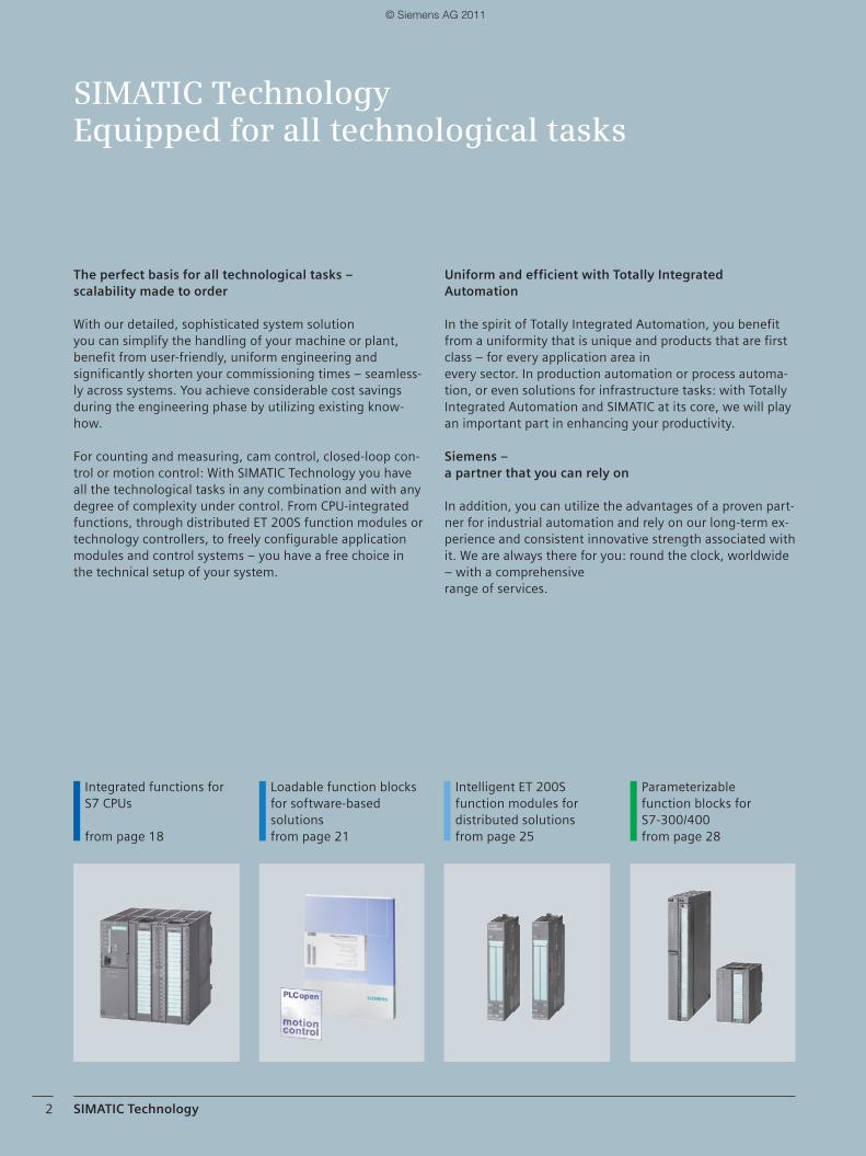
The perfect basis for all technological tasks – scalability made to order
With our detailed, sophisticated system solution you can simplify the handling of your machine or plant, benefit from user-friendly, uniform engineering and significantly shorten your commissioning times – seamless-ly across systems. You achieve considerable cost savings during the engineering phase by utilizing existing know-how.
For counting and measuring, cam control, closed-loop con-trol or motion control: With SIMATIC Technology you have all the technological tasks in any combination and with any degree of complexity under control. From CPU-integrated functions, through distributed ET 200S function modules or technology controllers, to freely configurable application modules and control systems – you have a free choice in the technical setup of your system.
SIMATIC TechnologyEquipped for all technological tasks
Loadable function blocks for software-based solutionsfrom page 21
Intelligent ET 200S function modules for distributed solutionsfrom page 25
Parameterizablefunction blocks for S7-300/400from page 28
Uniform and efficient with Totally Integrated Automation
In the spirit of Totally Integrated Automation, you benefit from a uniformity that is unique and products that are first class – for every application area in every sector. In production automation or process automa-tion, or even solutions for infrastructure tasks: with Totally Integrated Automation and SIMATIC at its core, we will play an important part in enhancing your productivity.
Siemens – a partner that you can rely on
In addition, you can utilize the advantages of a proven part-ner for industrial automation and rely on our long-term ex-perience and consistent innovative strength associated with it. We are always there for you: round the clock, worldwide – with a comprehensive range of services.
Integrated functions for S7 CPUs
from page 18
02_03__EN_Einstieg_Inhalt___Technology___04_2011.indd 202_03__EN_Einstieg_Inhalt___Technology___04_2011.indd 2 25.03.2011 13:47:3525.03.2011 13:47:35
© Siemens AG 2011
SIMATIC Technology 3
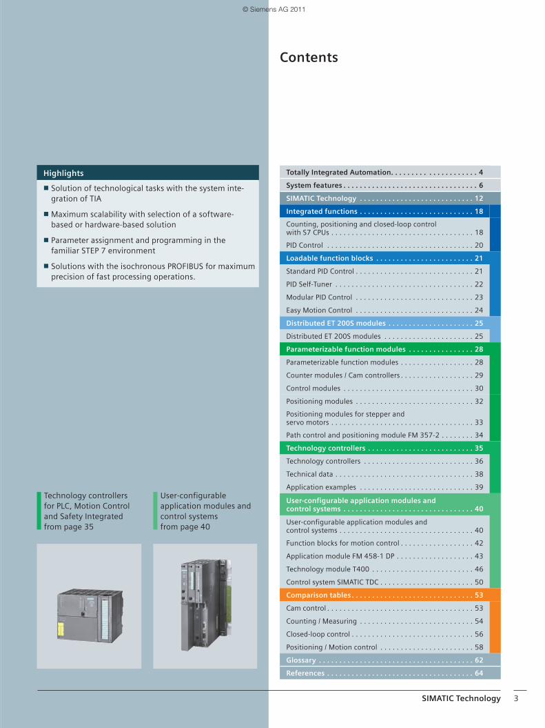
Highlights
■ Solution of technological tasks with the system inte-gration of TIA
■ Maximum scalability with selection of a software-based or hardware-based solution
■ Parameter assignment and programming in the familiar STEP 7 environment
■ Solutions with the isochronous PROFIBUS for maximum precision of fast processing operations.
Contents
Totally Integrated Automation. . . . . . . . . . . . . . . . . . . . . 4
System features . . . . . . . . . . . . . . . . . . . . . . . . . . . . . . . . . 6
SIMATIC Technology . . . . . . . . . . . . . . . . . . . . . . . . . . . . 12
Integrated functions . . . . . . . . . . . . . . . . . . . . . . . . . . . . 18
Counting, positioning and closed-loop control with S7 CPUs . . . . . . . . . . . . . . . . . . . . . . . . . . . . . . . . . . . 18
PID Control . . . . . . . . . . . . . . . . . . . . . . . . . . . . . . . . . . . . 20
Loadable function blocks . . . . . . . . . . . . . . . . . . . . . . . . 21
Standard PID Control . . . . . . . . . . . . . . . . . . . . . . . . . . . . . 21
PID Self-Tuner . . . . . . . . . . . . . . . . . . . . . . . . . . . . . . . . . . 22
Modular PID Control . . . . . . . . . . . . . . . . . . . . . . . . . . . . . 23
Easy Motion Control . . . . . . . . . . . . . . . . . . . . . . . . . . . . . 24
Distributed ET 200S modules . . . . . . . . . . . . . . . . . . . . . 25
Distributed ET 200S modules . . . . . . . . . . . . . . . . . . . . . . 25
Parameterizable function modules . . . . . . . . . . . . . . . . 28
Parameterizable function modules . . . . . . . . . . . . . . . . . . 28
Counter modules / Cam controllers . . . . . . . . . . . . . . . . . . 29
Control modules . . . . . . . . . . . . . . . . . . . . . . . . . . . . . . . . 30
Positioning modules . . . . . . . . . . . . . . . . . . . . . . . . . . . . . 32
Positioning modules for stepper and servo motors . . . . . . . . . . . . . . . . . . . . . . . . . . . . . . . . . . . 33
Path control and positioning module FM 357-2 . . . . . . . . 34
Technology controllers . . . . . . . . . . . . . . . . . . . . . . . . . . 35
Technology controllers . . . . . . . . . . . . . . . . . . . . . . . . . . . 36
Technical data . . . . . . . . . . . . . . . . . . . . . . . . . . . . . . . . . . 38
Application examples . . . . . . . . . . . . . . . . . . . . . . . . . . . . 39
User-configurable application modules and control systems . . . . . . . . . . . . . . . . . . . . . . . . . . . . . . . . 40
User-configurable application modules andcontrol systems . . . . . . . . . . . . . . . . . . . . . . . . . . . . . . . . . 40
Function blocks for motion control . . . . . . . . . . . . . . . . . . 42
Application module FM 458-1 DP . . . . . . . . . . . . . . . . . . . 43
Technology module T400 . . . . . . . . . . . . . . . . . . . . . . . . . 46
Control system SIMATIC TDC . . . . . . . . . . . . . . . . . . . . . . . 50
Comparison tables . . . . . . . . . . . . . . . . . . . . . . . . . . . . . . 53
Cam control . . . . . . . . . . . . . . . . . . . . . . . . . . . . . . . . . . . . 53
Counting / Measuring . . . . . . . . . . . . . . . . . . . . . . . . . . . . 54
Closed-loop control . . . . . . . . . . . . . . . . . . . . . . . . . . . . . . 56
Positioning / Motion control . . . . . . . . . . . . . . . . . . . . . . . 58
Glossary . . . . . . . . . . . . . . . . . . . . . . . . . . . . . . . . . . . . . . 62
References . . . . . . . . . . . . . . . . . . . . . . . . . . . . . . . . . . . . 64
Technology controllers for PLC, Motion Control and Safety Integratedfrom page 35
User-configurableapplication modules and control systemsfrom page 40
02_03__EN_Einstieg_Inhalt___Technology___04_2011.indd 302_03__EN_Einstieg_Inhalt___Technology___04_2011.indd 3 29.03.2011 12:42:0329.03.2011 12:42:03
© Siemens AG 2011
4 System features
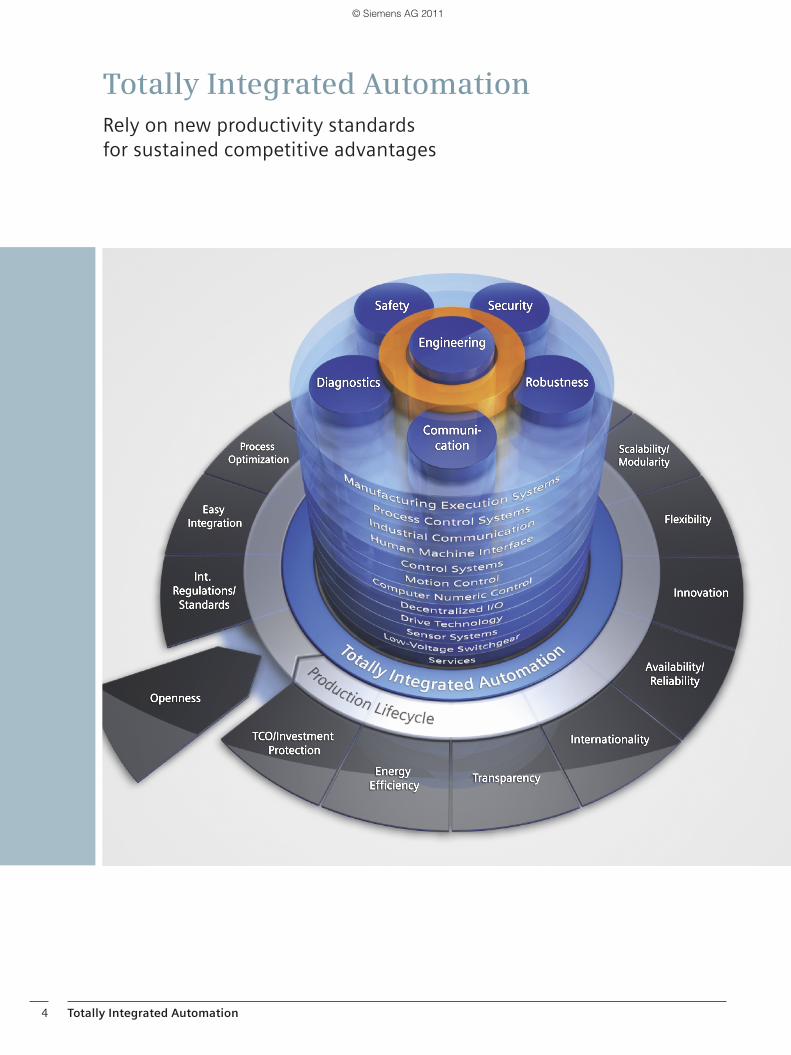
Totally Integrated AutomationRely on new productivity standards for sustained competitive advantages
Totally Integrated Automation
04_05__EN_TIA___Technology__02_2011.indd 404_05__EN_TIA___Technology__02_2011.indd 4 24.02.2011 16:14:4924.02.2011 16:14:49
© Siemens AG 2011
System features 5
To be able to respond to the increasing international competitive pressure, it is more important than ever to consistently make full use of the potential for optimiza-tion – over the complete lifecycle of a machine or plant.
Optimized processes reduce the total cost of owner-ship, shorten the time to market, and improve quality. This perfect balance between quality, time, and costs is now, more than ever, the decisive success factor in in-dustry.
Totally Integrated Automation is optimally aligned to all requirements and open for international standards and third-party systems. With its six characteristic system features, Totally Integrated Automation supports the complete lifecycle of a machine or plant. The complete system architecture offers holistic solutions for every automation segment on the basis of a comprehensive range of products.
SIMATIC: more efficient and systematic automation
SIMATIC, a core component of Totally Integrated Auto-mation, includes a variety of standardized, flexible, and scalable products – such as SIMATIC Technology for technological tasks presented in this brochure. SIMATIC is currently considered to be the global num-ber one in automation. One of the decisive reasons for this is that SIMATIC exhibits the six system features of Totally Integrated Automation:• Engineering• Communication• Diagnostics• Safety• Security• Robustness
In addition, SIMATIC features two additional system features:• Technology• High availability
You can find more about the system features and the resulting advantages in the following chapter “System features”.
Totally Integrated Automation
04_05__EN_TIA___Technology__02_2011.indd 504_05__EN_TIA___Technology__02_2011.indd 5 24.02.2011 16:13:4824.02.2011 16:13:48
© Siemens AG 2011
6 System features
System features
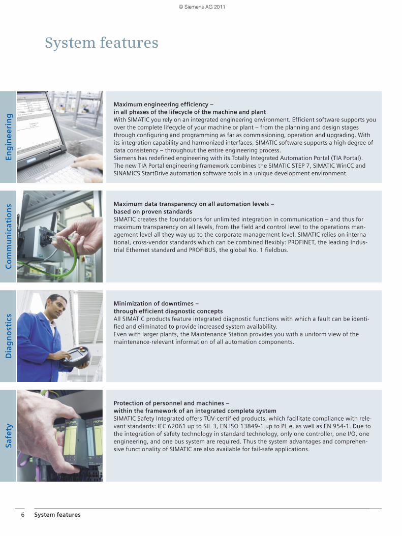
Minimization of downtimes – through efficient diagnostic conceptsAll SIMATIC products feature integrated diagnostic functions with which a fault can be identi-fied and eliminated to provide increased system availability. Even with larger plants, the Maintenance Station provides you with a uniform view of the maintenance-relevant information of all automation components.
Protection of personnel and machines – within the framework of an integrated complete systemSIMATIC Safety Integrated offers TÜV-certified products, which facilitate compliance with rele-vant standards: IEC 62061 up to SIL 3, EN ISO 13849-1 up to PL e, as well as EN 954-1. Due to the integration of safety technology in standard technology, only one controller, one I/O, one engineering, and one bus system are required. Thus the system advantages and comprehen-sive functionality of SIMATIC are also available for fail-safe applications.
En
gin
ee
rin
gC
om
mu
nic
atio
ns
Dia
gn
ost
ics
Safe
ty
Maximum data transparency on all automation levels – based on proven standardsSIMATIC creates the foundations for unlimited integration in communication – and thus for maximum transparency on all levels, from the field and control level to the operations man-agement level all they way up to the corporate management level. SIMATIC relies on interna-tional, cross-vendor standards which can be combined flexibly: PROFINET, the leading Indus-trial Ethernet standard and PROFIBUS, the global No. 1 fieldbus.
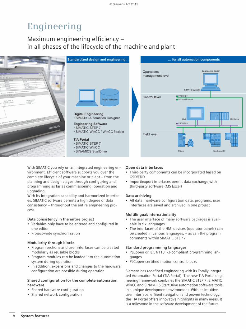
Maximum engineering efficiency – in all phases of the lifecycle of the machine and plantWith SIMATIC you rely on an integrated engineering environment. Efficient software supports you over the complete lifecycle of your machine or plant – from the planning and design stages through configuring and programming as far as commissioning, operation and upgrading. With its integration capability and harmonized interfaces, SIMATIC software supports a high degree of data consistency – throughout the entire engineering process.Siemens has redefined engineering with its Totally Integrated Automation Portal (TIA Portal). The new TIA Portal engineering framework combines the SIMATIC STEP 7, SIMATIC WinCC and SINAMICS StartDrive automation software tools in a unique development environment.
06_07__EN_Systemeigenschaften___02_2011.indd 606_07__EN_Systemeigenschaften___02_2011.indd 6 24.02.2011 15:50:4924.02.2011 15:50:49
© Siemens AG 2011
System features 7
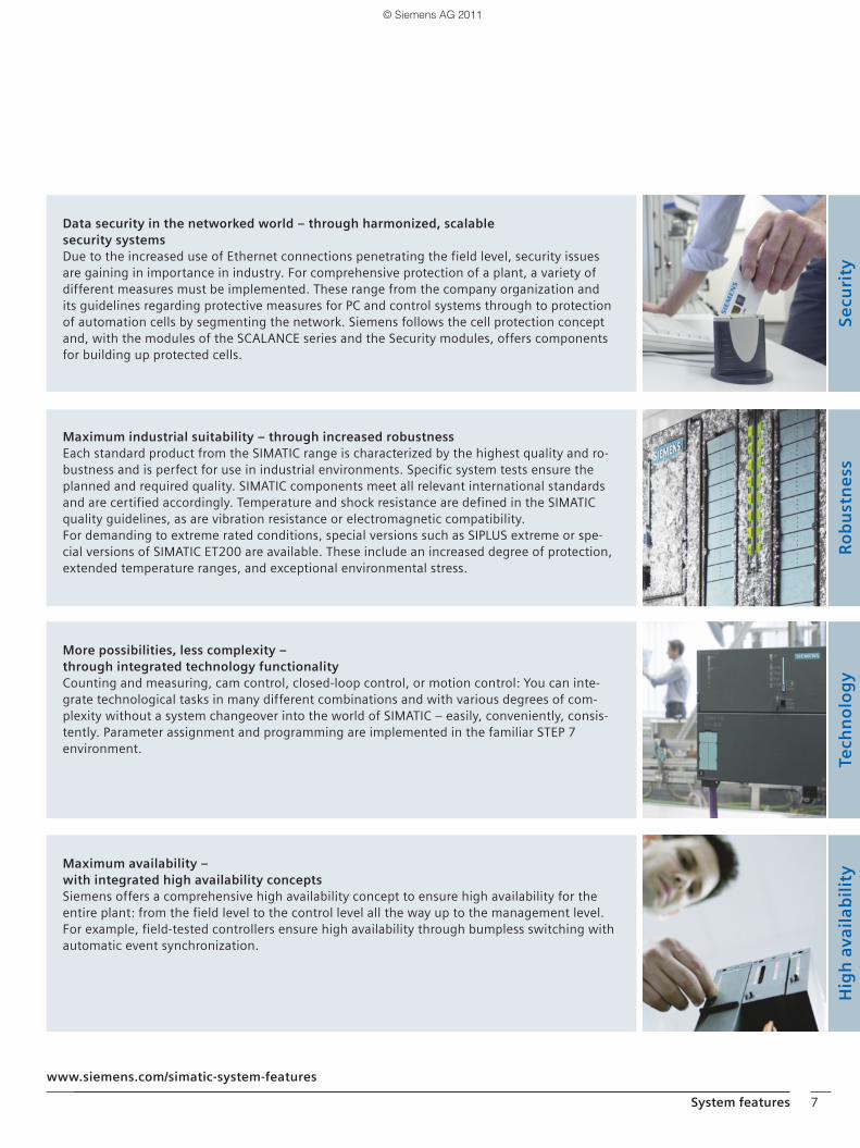
Data security in the networked world – through harmonized, scalablesecurity systemsDue to the increased use of Ethernet connections penetrating the field level, security issues are gaining in importance in industry. For comprehensive protection of a plant, a variety of different measures must be implemented. These range from the company organization and its guidelines regarding protective measures for PC and control systems through to protection of automation cells by segmenting the network. Siemens follows the cell protection concept and, with the modules of the SCALANCE series and the Security modules, offers components for building up protected cells.
Maximum industrial suitability – through increased robustnessEach standard product from the SIMATIC range is characterized by the highest quality and ro-bustness and is perfect for use in industrial environments. Specific system tests ensure the planned and required quality. SIMATIC components meet all relevant international standards and are certified accordingly. Temperature and shock resistance are defined in the SIMATIC quality guidelines, as are vibration resistance or electromagnetic compatibility.For demanding to extreme rated conditions, special versions such as SIPLUS extreme or spe-cial versions of SIMATIC ET200 are available. These include an increased degree of protection, extended temperature ranges, and exceptional environmental stress.
Maximum availability – with integrated high availability conceptsSiemens offers a comprehensive high availability concept to ensure high availability for the entire plant: from the field level to the control level all the way up to the management level. For example, field-tested controllers ensure high availability through bumpless switching with automatic event synchronization.
Secu
rity
Ro
bu
stn
ess
Tech
no
log
yH
igh
ava
ilab
ilit
y
www.siemens.com/simatic-system-features
More possibilities, less complexity – through integrated technology functionalityCounting and measuring, cam control, closed-loop control, or motion control: You can inte-grate technological tasks in many different combinations and with various degrees of com-plexity without a system changeover into the world of SIMATIC – easily, conveniently, consis-tently. Parameter assignment and programming are implemented in the familiar STEP 7 environment.
06_15__EN_Systemeigenschaften___02_2011.indd 706_15__EN_Systemeigenschaften___02_2011.indd 7 24.02.2011 15:53:5524.02.2011 15:53:55
© Siemens AG 2011
8 System features
With SIMATIC you rely on an integrated engineering en-vironment. Efficient software supports you over the complete lifecycle of your machine or plant – from the planning and design stages through configuring and programming as far as commissioning, operation and upgrading.With its integration capability and harmonized interfac-es, SIMATIC software permits a high degree of data consistency – throughout the entire engineering pro-cess.
Data consistency in the entire project• Variables only have to be entered and configured in
one editor• Project-wide synchronization
Modularity through blocks• Program sections and user interfaces can be created
modularly as reusable blocks• Program modules can be loaded into the automation
system during operation• In addition, expansions and changes to the hardware
configuration are possible during operation
Shared configuration for the complete automation hardware • Shared hardware configuration• Shared network configuration
Open data interfaces• Third-party components can be incorporated based on
GSD/EDD• Import/export interfaces permit data exchange with
third-party software (MS Excel)
Data archiving• All data, hardware configuration data, programs, user
interfaces are saved and archived in one project
Multilingual/internationality• The user interface of many software packages is avail-
able in six languages• The interfaces of the HMI devices (operator panels) can
be created in various languages, – as can the program comments within SIMATIC STEP 7
Standard programming languages• PLCopen or IEC 61131-3-compliant programming lan-
guages • PLCopen-certified motion control blocks
Siemens has redefined engineering with its Totally Integra-ted Automation Portal (TIA Portal). The new TIA Portal engi-neering framework combines the SIMATIC STEP 7, SIMATIC WinCC and SINAMICS StartDrive automation software tools in a unique development environment. With its intuitive user interface, effiient navigation and proven technology, the TIA Portal offers innovative highlights in many areas. It is a milestone in the software development of the future.
EngineeringMaximum engineering efficiency – in all phases of the lifecycle of the machine and plant
PROFIBUS
Operations management level
Control level
Distributed IO
Controller
Drives
Field level
SIMATIC WinCC
Project database
PROFINET
Industrial Ethernet
HMI
Engineering Station
Standardized design and engineering … … for all automation components
Digital Engineering SIMATIC Automation Designer
Engineering Software SIMATIC STEP SIMATIC WinCC WinCC le ible
TIA Portal SIMATIC STEP SIMATIC WinCC SINAMICS StartDrive
06_15__EN_Systemeigenschaften___02_2011.indd 806_15__EN_Systemeigenschaften___02_2011.indd 8 24.02.2011 15:54:5424.02.2011 15:54:54
© Siemens AG 2011
System features 9
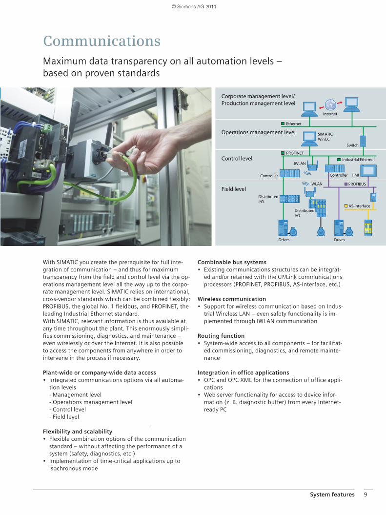
With SIMATIC you create the prerequisite for full inte-gration of communication – and thus for maximum transparency from the field and control level via the op-erations management level all the way up to the corpo-rate management level. SIMATIC relies on international, cross-vendor standards which can be combined flexibly: PROFIBUS, the global No. 1 fieldbus, and PROFINET, the leading Industrial Ethernet standard.With SIMATIC, relevant information is thus available at any time throughout the plant. This enormously simpli-fies commissioning, diagnostics, and maintenance – even wirelessly or over the Internet. It is also possible to access the components from anywhere in order to intervene in the process if necessary.
Plant-wide or company-wide data access• Integrated communications options via all automa-
tion levels - Management level - Operations management level - Control level - Field level
Flexibility and scalability• Flexible combination options of the communication
standard – without affecting the performance of a system (safety, diagnostics, etc.)
• Implementation of time-critical applications up to isochronous mode
Combinable bus systems• Existing communications structures can be integrat-
ed and/or retained with the CP/Link communications processors (PROFINET, PROFIBUS, AS-Interface, etc.)
Wireless communication• Support for wireless communication based on Indus-
trial Wireless LAN – even safety functionality is im-plemented through IWLAN communication
Routing function• System-wide access to all components – for facilitat-
ed commissioning, diagnostics, and remote mainte-nance
Integration in office applications• OPC and OPC XML for the connection of office appli-
cations• Web server functionality for access to device infor-
mation (z. B. diagnostic buffer) from every Internet-ready PC
CommunicationsMaximum data transparency on all automation levels – based on proven standards
DistributedI/O
Controller
SIMATICWinCC
Internet
Corporate management level/Production management level
Control level
Field level
Operations management level
Switch
PROFINET
HMI
PROFIBUS
AS-Interface
Ethernet
Industrial Ethernet
DistributedI/O
IWLAN
IWLAN
Drives
Controller
Drives
06_15__EN_Systemeigenschaften___02_2011.indd 906_15__EN_Systemeigenschaften___02_2011.indd 9 24.02.2011 15:55:0424.02.2011 15:55:04
© Siemens AG 2011
10 System features
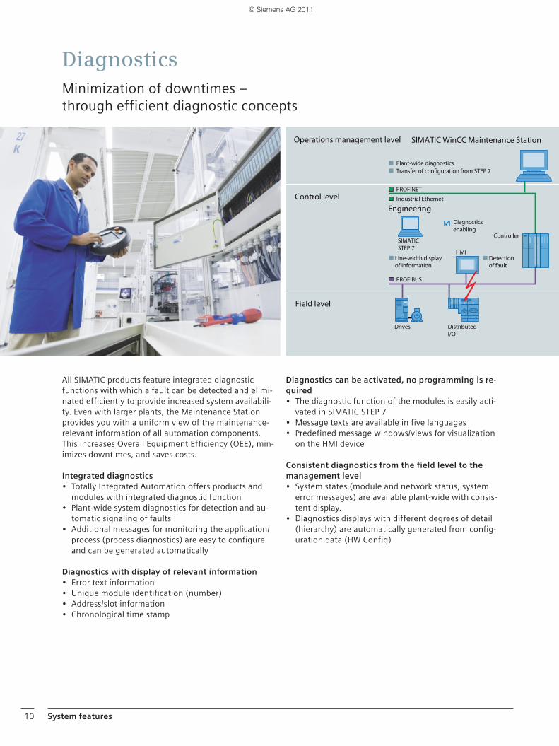
All SIMATIC products feature integrated diagnostic functions with which a fault can be detected and elimi-nated efficiently to provide increased system availabili-ty. Even with larger plants, the Maintenance Station provides you with a uniform view of the maintenance-relevant information of all automation components. This increases Overall Equipment Efficiency (OEE), min-imizes downtimes, and saves costs.
Integrated diagnostics• Totally Integrated Automation offers products and
modules with integrated diagnostic function• Plant-wide system diagnostics for detection and au-
tomatic signaling of faults• Additional messages for monitoring the application/
process (process diagnostics) are easy to configure and can be generated automatically
Diagnostics with display of relevant information• Error text information• Unique module identification (number)• Address/slot information• Chronological time stamp
Diagnostics can be activated, no programming is re-quired • The diagnostic function of the modules is easily acti-
vated in SIMATIC STEP 7 • Message texts are available in five languages • Predefined message windows/views for visualization
on the HMI device
Consistent diagnostics from the field level to the management level • System states (module and network status, system
error messages) are available plant-wide with consis-tent display.
• Diagnostics displays with different degrees of detail (hierarchy) are automatically generated from config-uration data (HW Config)
DiagnosticsMinimization of downtimes –through efficient diagnostic concepts
Operations management level
Plant-wide diagnostics
Diagnosticsenabling
Control level
Drives DistributedI/O
Transfer of configuration from STEP 7
Engineering
Field level
SIMATIC WinCC Maintenance Station
HMI
SIMATICSTEP 7
PROFINET
PROFIBUS
Industrial Ethernet
Controller
Line-width display of information
Detectionof fault
06_15__EN_Systemeigenschaften___02_2011.indd 1006_15__EN_Systemeigenschaften___02_2011.indd 10 24.02.2011 15:55:3024.02.2011 15:55:30
© Siemens AG 2011
System features 11
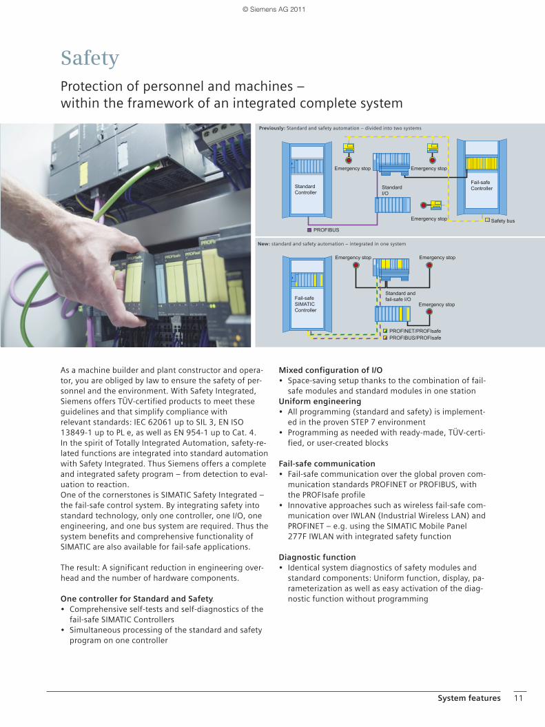
As a machine builder and plant constructor and opera-tor, you are obliged by law to ensure the safety of per-sonnel and the environment. With Safety Integrated, Siemens offers TÜV-certified products to meet these guidelines and that simplify compliance withrelevant standards: IEC 62061 up to SIL 3, EN ISO 13849-1 up to PL e, as well as EN 954-1 up to Cat. 4.In the spirit of Totally Integrated Automation, safety-re-lated functions are integrated into standard automation with Safety Integrated. Thus Siemens offers a complete and integrated safety program – from detection to eval-uation to reaction.One of the cornerstones is SIMATIC Safety Integrated – the fail-safe control system. By integrating safety into standard technology, only one controller, one I/O, one engineering, and one bus system are required. Thus the system benefits and comprehensive functionality of SIMATIC are also available for fail-safe applications.
The result: A significant reduction in engineering over-head and the number of hardware components.
One controller for Standard and Safety• Comprehensive self-tests and self-diagnostics of the
fail-safe SIMATIC Controllers• Simultaneous processing of the standard and safety
program on one controller
Mixed configuration of I/O • Space-saving setup thanks to the combination of fail-
safe modules and standard modules in one stationUniform engineering• All programming (standard and safety) is implement-
ed in the proven STEP 7 environment• Programming as needed with ready-made, TÜV-certi-
fied, or user-created blocks
Fail-safe communication• Fail-safe communication over the global proven com-
munication standards PROFINET or PROFIBUS, with the PROFIsafe profile
• Innovative approaches such as wireless fail-safe com-munication over IWLAN (Industrial Wireless LAN) and PROFINET – e.g. using the SIMATIC Mobile Panel 277F IWLAN with integrated safety function
Diagnostic function• Identical system diagnostics of safety modules and
standard components: Uniform function, display, pa-rameterization as well as easy activation of the diag-nostic function without programming
SafetyProtection of personnel and machines –within the framework of an integrated complete system
New: standard and safety automation – integrated in one system
Previously: Standard and safety automation – divided into two systems
Emergency stop
Fail-safe SIMATIC Controller
Emergency stop
Emergency stop
Safety busEmergency stop
Emergency stop Emergency stop
Standard I/O
Fail-safe Controller
Standard and fail-safe I/O
Standard Controller
PROFIBUS/PROFIsafePROFINET/PROFIsafe
PROFIBUS
06_15__EN_Systemeigenschaften___02_2011.indd 1106_15__EN_Systemeigenschaften___02_2011.indd 11 24.02.2011 15:55:5024.02.2011 15:55:50
© Siemens AG 2011
12 SIMATIC Technology
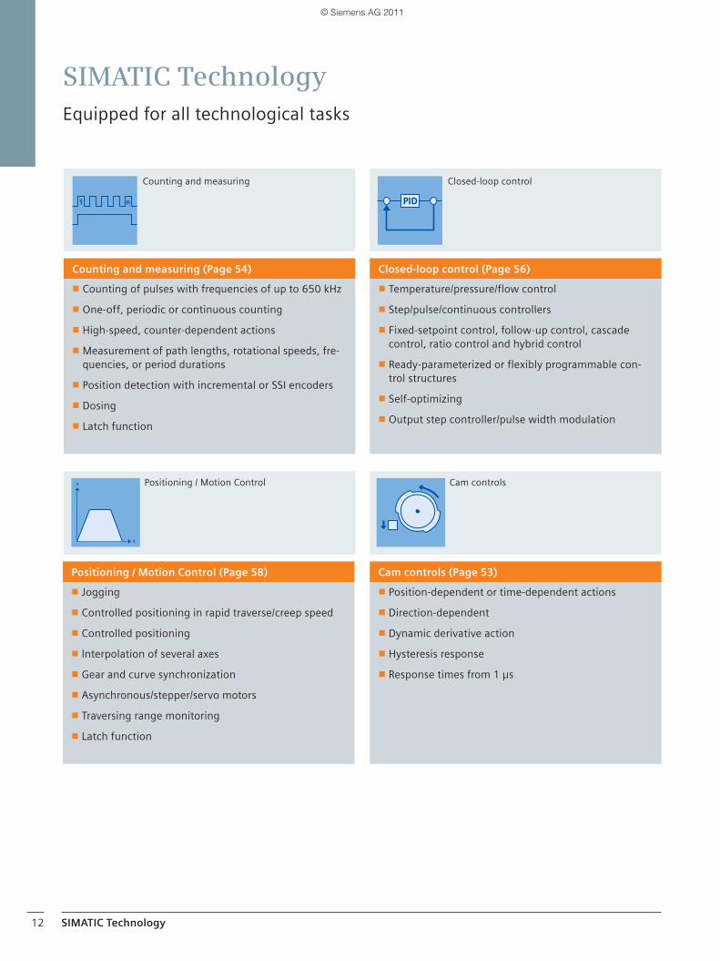
SIMATIC TechnologyEquipped for all technological tasks
Counting and measuring (Page 54)
■ Counting of pulses with frequencies of up to 650 kHz
■ One-off, periodic or continuous counting
■ High-speed, counter-dependent actions
■ Measurement of path lengths, rotational speeds, fre-quencies, or period durations
■ Position detection with incremental or SSI encoders
■ Dosing
■ Latch function
Closed-loop control (Page 56)
■ Temperature/pressure/flow control
■ Step/pulse/continuous controllers
■ Fixed-setpoint control, follow-up control, cascade control, ratio control and hybrid control
■ Ready-parameterized or flexibly programmable con-trol structures
■ Self-optimizing
■ Output step controller/pulse width modulation
Positioning / Motion Control (Page 58)
■ Jogging
■ Controlled positioning in rapid traverse/creep speed
■ Controlled positioning
■ Interpolation of several axes
■ Gear and curve synchronization
■ Asynchronous/stepper/servo motors
■ Traversing range monitoring
■ Latch function
Cam controls (Page 53)
■ Position-dependent or time-dependent actions
■ Direction-dependent
■ Dynamic derivative action
■ Hysteresis response
■ Response times from 1 μs
Counting and measuring Closed-loop control
Positioning / Motion Control Cam controls
06_13__EN_Systemeigenschaften___02_2011.indd 1206_13__EN_Systemeigenschaften___02_2011.indd 12 25.03.2011 13:26:1025.03.2011 13:26:10
© Siemens AG 2011
SIMATIC Technology 13
Mastering high-speed processes through isochronous mode
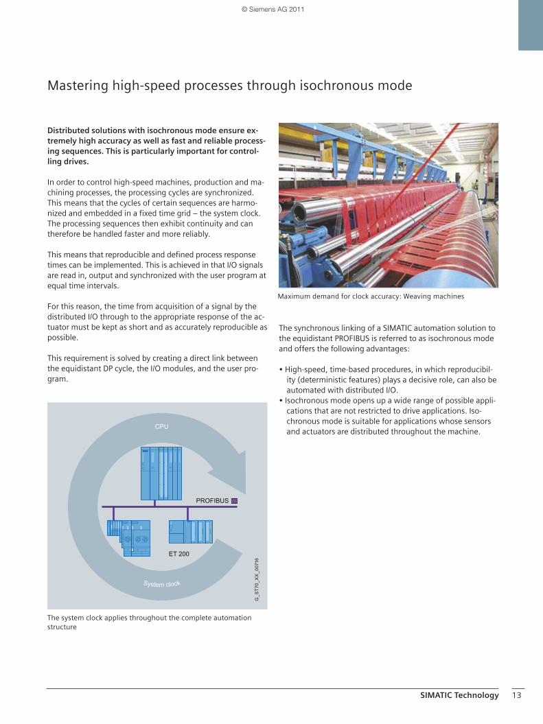
Distributed solutions with isochronous mode ensure ex-tremely high accuracy as well as fast and reliable process-ing sequences. This is particularly important for control-ling drives.
In order to control high-speed machines, production and ma-chining processes, the processing cycles are synchronized. This means that the cycles of certain sequences are harmo-nized and embedded in a fixed time grid – the system clock. The processing sequences then exhibit continuity and can therefore be handled faster and more reliably.
This means that reproducible and defined process responsetimes can be implemented. This is achieved in that I/O signals are read in, output and synchronized with the user program at equal time intervals.
For this reason, the time from acquisition of a signal by thedistributed I/O through to the appropriate response of the ac-tuator must be kept as short and as accurately reproducible as possible.
This requirement is solved by creating a direct link betweenthe equidistant DP cycle, the I/O modules, and the user pro-gram.
The synchronous linking of a SIMATIC automation solution to the equidistant PROFIBUS is referred to as isochronous mode and offers the following advantages:
• High-speed, time-based procedures, in which reproducibil-ity (deterministic features) plays a decisive role, can also be automated with distributed I/O.
• Isochronous mode opens up a wide range of possible appli-cations that are not restricted to drive applications. Iso-chronous mode is suitable for applications whose sensors and actuators are distributed throughout the machine.
Maximum demand for clock accuracy: Weaving machines
System clock
G_S
T70_
XX
_007
16
ET 200
PROFIBUS
CPU
The system clock applies throughout the complete automation structure
06_13__EN_Systemeigenschaften___02_2011.indd 1306_13__EN_Systemeigenschaften___02_2011.indd 13 25.03.2011 13:26:1125.03.2011 13:26:11
© Siemens AG 2011
SIMATIC Technology14
Product spectrum –Product lines and applications for SIMATIC Technology
SIMATIC Technology represents the greatest possible freedom in the choice of design and scalability of the hardware and software.
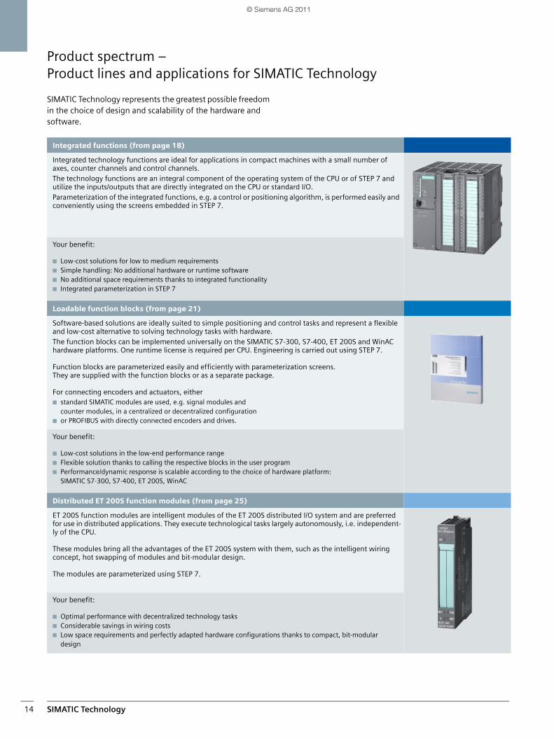
Integrated functions (from page 18)
Integrated technology functions are ideal for applications in compact machines with a small number of axes, counter channels and control channels.The technology functions are an integral component of the operating system of the CPU or of STEP 7 and utilize the inputs/outputs that are directly integrated on the CPU or standard I/O.Parameterization of the integrated functions, e.g. a control or positioning algorithm, is performed easily and conveniently using the screens embedded in STEP 7.
Your benefit:
■ Low-cost solutions for low to medium requirements■ Simple handling: No additional hardware or runtime software■ No additional space requirements thanks to integrated functionality■ Integrated parameterization in STEP 7
Loadable function blocks (from page 21)
Software-based solutions are ideally suited to simple positioning and control tasks and represent a flexible and low-cost alternative to solving technology tasks with hardware. The function blocks can be implemented universally on the SIMATIC S7-300, S7-400, ET 200S and WinAC hardware platforms. One runtime license is required per CPU. Engineering is carried out using STEP 7.
Function blocks are parameterized easily and efficiently with parameterization screens. They are supplied with the function blocks or as a separate package.
For connecting encoders and actuators, either■ standard SIMATIC modules are used, e.g. signal modules and
counter modules, in a centralized or decentralized configuration■ or PROFIBUS with directly connected encoders and drives.
Your benefit:
■ Low-cost solutions in the low-end performance range■ Flexible solution thanks to calling the respective blocks in the user program■ Performance/dynamic response is scalable according to the choice of hardware platform:
SIMATIC S7-300, S7-400, ET 200S, WinAC
Distributed ET 200S function modules (from page 25)
ET 200S function modules are intelligent modules of the ET 200S distributed I/O system and are preferred for use in distributed applications. They execute technological tasks largely autonomously, i.e. independent-ly of the CPU.
These modules bring all the advantages of the ET 200S system with them, such as the intelligent wiring concept, hot swapping of modules and bit-modular design.
The modules are parameterized using STEP 7.
Your benefit:
■ Optimal performance with decentralized technology tasks■ Considerable savings in wiring costs■ Low space requirements and perfectly adapted hardware configurations thanks to compact, bit-modular
design
SIMATIC_Technology_04_2011_en.book Seite 14 Freitag, 25. März 2011 3:51 15
© Siemens AG 2011
SIMATIC Technology 15
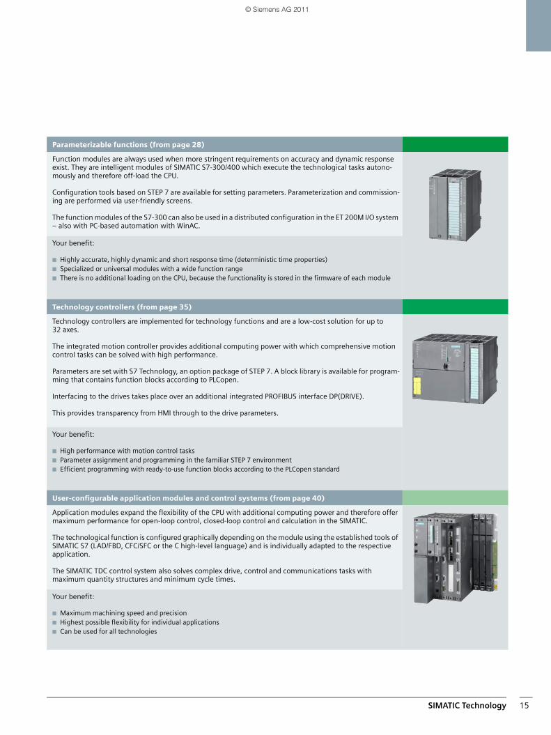
Parameterizable functions (from page 28)
Function modules are always used when more stringent requirements on accuracy and dynamic response exist. They are intelligent modules of SIMATIC S7-300/400 which execute the technological tasks autono-mously and therefore off-load the CPU.
Configuration tools based on STEP 7 are available for setting parameters. Parameterization and commission-ing are performed via user-friendly screens.
The function modules of the S7-300 can also be used in a distributed configuration in the ET 200M I/O system – also with PC-based automation with WinAC.
Your benefit:
■ Highly accurate, highly dynamic and short response time (deterministic time properties)■ Specialized or universal modules with a wide function range■ There is no additional loading on the CPU, because the functionality is stored in the firmware of each module
Technology controllers (from page 35)
Technology controllers are implemented for technology functions and are a low-cost solution for up to 32 axes.
The integrated motion controller provides additional computing power with which comprehensive motion control tasks can be solved with high performance.
Parameters are set with S7 Technology, an option package of STEP 7. A block library is available for program-ming that contains function blocks according to PLCopen.
Interfacing to the drives takes place over an additional integrated PROFIBUS interface DP(DRIVE).
This provides transparency from HMI through to the drive parameters.
Your benefit:
■ High performance with motion control tasks■ Parameter assignment and programming in the familiar STEP 7 environment■ Efficient programming with ready-to-use function blocks according to the PLCopen standard
User-configurable application modules and control systems (from page 40)
Application modules expand the flexibility of the CPU with additional computing power and therefore offer maximum performance for open-loop control, closed-loop control and calculation in the SIMATIC.
The technological function is configured graphically depending on the module using the established tools of SIMATIC S7 (LAD/FBD, CFC/SFC or the C high-level language) and is individually adapted to the respective application.
The SIMATIC TDC control system also solves complex drive, control and communications tasks withmaximum quantity structures and minimum cycle times.
Your benefit:
■ Maximum machining speed and precision■ Highest possible flexibility for individual applications■ Can be used for all technologies
SIMATIC_Technology_04_2011_en.book Seite 15 Freitag, 25. März 2011 3:51 15
© Siemens AG 2011
SIMATIC Technology16
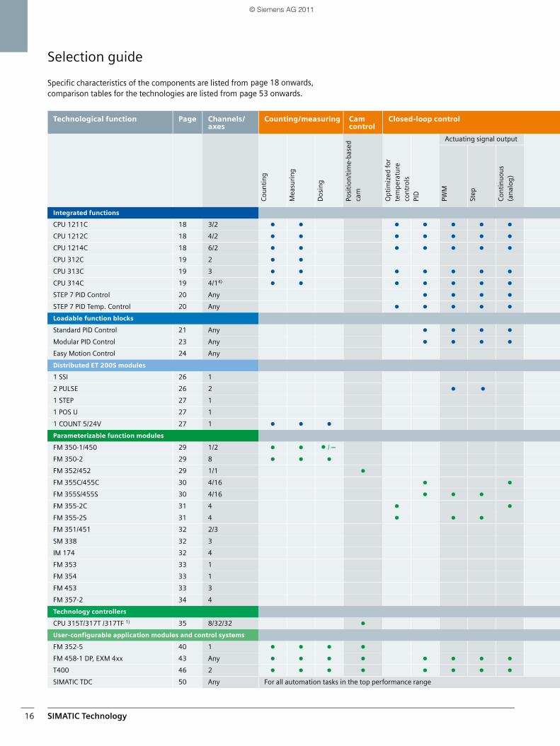
Selection guide
Specific characteristics of the components are listed from comparison tables for the technologies are listed from
Technological function Page Channels/axes
Counting/measuring Cam control
Closed-loop control
Cou
nti
ng
Mea
suri
ng
Do
sin
g
Posi
tion
/tim
e-ba
sed
cam
Opt
imiz
ed f
or
tem
pera
ture
co
ntr
ols
PID
Actuating signal output
PWM
Step
Con
tin
uo
us
(an
alog
)
Integrated functions
CPU 1211C 18 3/2 k k k k k k k
CPU 1212C 18 4/2 k k k k k k k
CPU 1214C 18 6/2 k k k k k k k
CPU 312C 19 2 k k
CPU 313C 19 3 k k k k k k k
CPU 314C 19 4/14)k k k k k k k
STEP 7 PID Control 20 Any k k k k
STEP 7 PID Temp. Control 20 Any k k k k k
Loadable function blocks
Standard PID Control 21 Any k k k k
Modular PID Control 23 Any k k k k
Easy Motion Control 24 Any
Distributed ET 200S modules
1 SSI 26 1
2 PULSE 26 2 k k
1 STEP 27 1
1 POS U 27 1
1 COUNT 5/24V 27 1 k k k
Parameterizable function modules
FM 350-1/450 29 1/2 k k k / –
FM 350-2 29 8 k k k
FM 352/452 29 1/1 k
FM 355C/455C 30 4/16 k k
FM 355S/455S 30 4/16 k k k
FM 355-2C 31 4 k k
FM 355-2S 31 4 k k k
FM 351/451 32 2/3
SM 338 32 3
IM 174 32 4
FM 353 33 1
FM 354 33 1
FM 453 33 3
FM 357-2 34 4
Technology controllers
CPU 315T/317T /317TF 1) 35 8/32/32 k
User-configurable application modules and control systems
FM 352-5 40 1 k k k k
FM 458-1 DP, EXM 4xx 43 Any k k k k k k k k
T400 46 2 k k k k k k k k
SIMATIC TDC 50 Any For all automation tasks in the top performance range
page 18 onwards, page 53 onwards.
SIMATIC_Technology_04_2011_en.book Seite 16 Freitag, 25. März 2011 3:51 15
© Siemens AG 2011
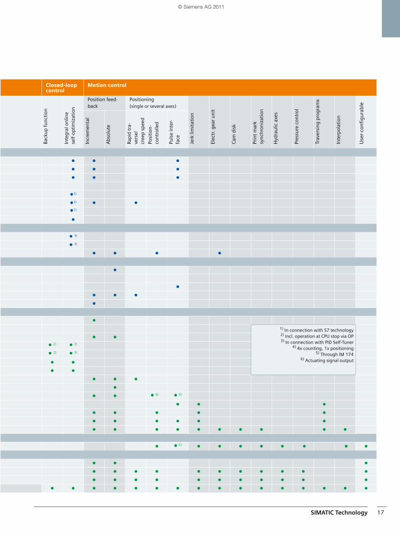
SIMATIC Technology 17
Closed-loop control
Motion control
Back
up
fun
ctio
n
Inte
gral
on
line
self
-opt
imiz
atio
n
Position feed-back
Positioning (single or several axes)
Jerk
lim
itat
ion
Elec
tr. g
ear
un
it
Cam
dis
k
Prin
t m
ark
syn
chro
niz
atio
n
Hyd
rau
lic a
xes
Pres
sure
con
tro
l
Trav
ersi
ng
pro
gram
s
Inte
rpo
lati
on
Use
r-co
nfi
gura
ble
Incr
emen
tal
Abs
olu
te
Rapi
d tr
a-ve
rse/
cree
p sp
eed
Posi
tion
-co
ntr
olle
d
Puls
e in
ter-
face
k k k
k k k
k k k
k3)
k3)
k k
k3)
k
k 3)
k 3)
k k k k
k
k
k k k
k
k
1) In connection with S7 technology2) Incl. operation at CPU stop via OP3) In connection with PID Self-Tuner
4) 4x counting, 1x positioning5) Through IM 174
6) Actuating signal output
k k
k 2)k 3)
k 2)k 3)
k k
k k
k k k
k
k k k 6)k 6)
k k k
k k k k k
k k k k k k
k k k k k k k k k k
k k 5)k k k k k k k k
k k k
k k k k k k k k k k k
k k k k k k k k k k k
k k k k k k k k k k k k k k k k
SIMATIC_Technology_04_2011_en.book Seite 17 Freitag, 25. März 2011 3:51 15
© Siemens AG 2011
Integrated functions18
Integrated functionsCounting, positioning and closed-loop control with S7 CPUs
The S7 CPUs offer different integrated functions for imple-menting simple counting, positioning and closed-loop control tasks.
S7-1200
Depending on the CPU, up to six high-speed counters are integrated, three at 100 kHz and three at 30 kHz. Optionally, using Signal Boards, 200 kHz (24 V or 5 V version) is available. They are used for the precise monitoring of incremental en-coders, frequency counting or high-speed counting of process events. Two high-speed outputs are integrated into the SIMATIC S7-1200 controller for use as pulse outputs. They can be used for the open-loop speed and position control of stepper motors and servo drives. They are easily configured using an axis technology object along with the internationally accepted PLCopen motion function blocks included withinthe SIMATIC STEP 7 Basic engineering system.
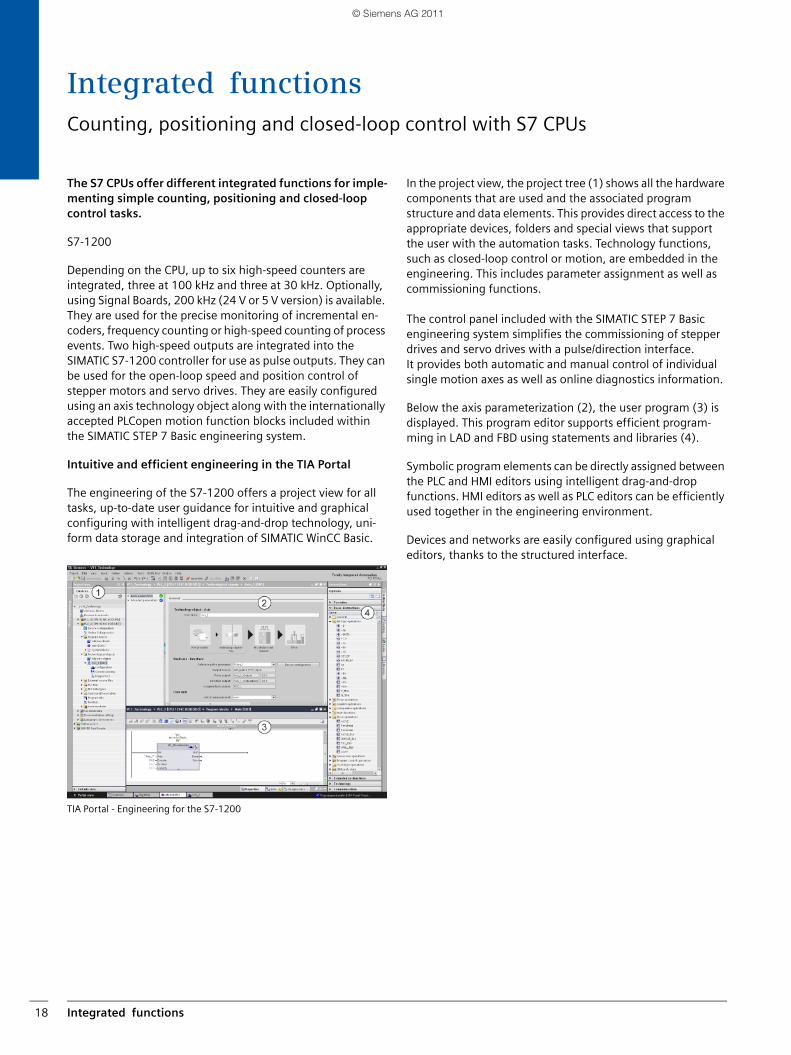
Intuitive and efficient engineering in the TIA Portal
The engineering of the S7-1200 offers a project view for all tasks, up-to-date user guidance for intuitive and graphical configuring with intelligent drag-and-drop technology, uni-form data storage and integration of SIMATIC WinCC Basic.
TIA Portal - Engineering for the S7-1200
In the project view, the project tree (1) shows all the hardware components that are used and the associated program structure and data elements. This provides direct access to the appropriate devices, folders and special views that support the user with the automation tasks. Technology functions, such as closed-loop control or motion, are embedded in the engineering. This includes parameter assignment as well as commissioning functions.
The control panel included with the SIMATIC STEP 7 Basic engineering system simplifies the commissioning of stepper drives and servo drives with a pulse/direction interface. It provides both automatic and manual control of individual single motion axes as well as online diagnostics information.
Below the axis parameterization (2), the user program (3) is displayed. This program editor supports efficient program-ming in LAD and FBD using statements and libraries (4).
Symbolic program elements can be directly assigned between the PLC and HMI editors using intelligent drag-and-drop functions. HMI editors as well as PLC editors can be efficiently used together in the engineering environment.
Devices and networks are easily configured using graphical editors, thanks to the structured interface.
SIMATIC_Technology_04_2011_en.book Seite 18 Freitag, 25. März 2011 3:51 15
© Siemens AG 2011
Integrated functions 19
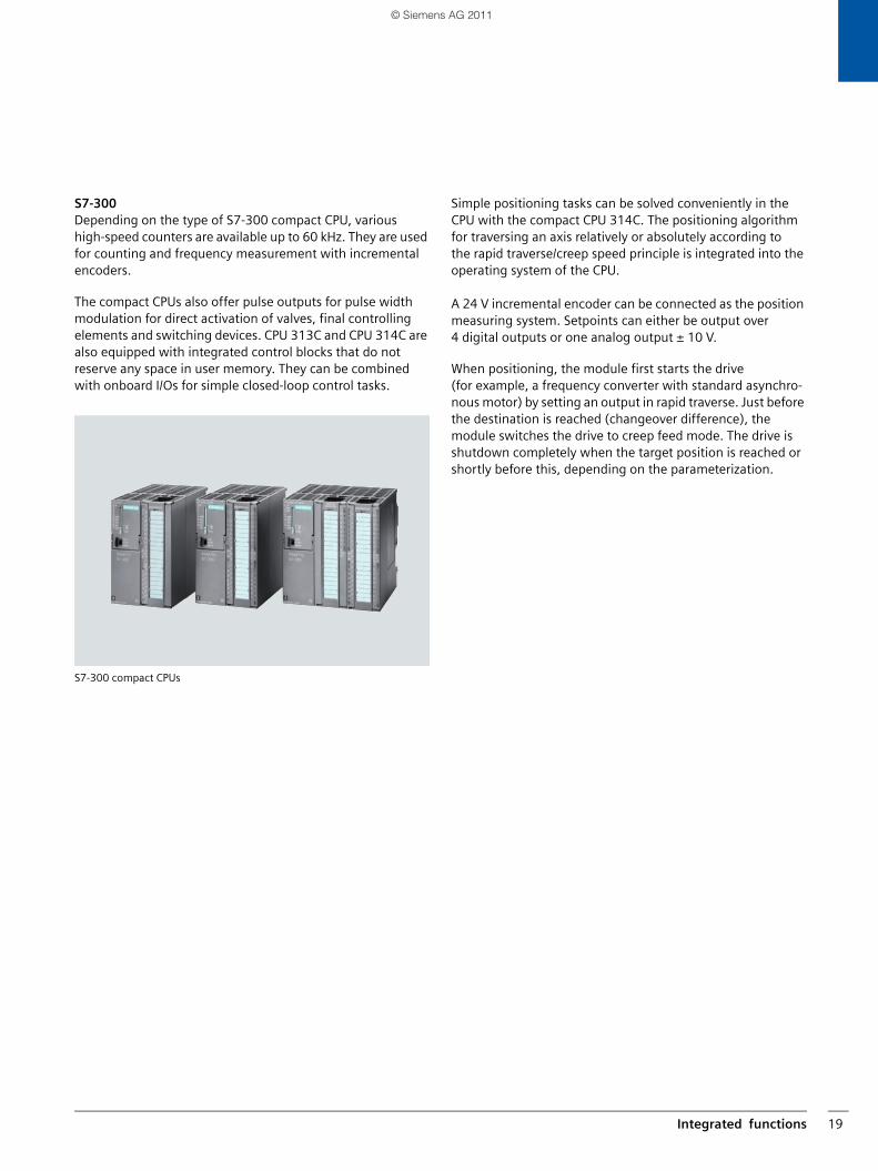
S7-300Depending on the type of S7-300 compact CPU, various high-speed counters are available up to 60 kHz. They are used for counting and frequency measurement with incremental encoders.
The compact CPUs also offer pulse outputs for pulse width modulation for direct activation of valves, final controlling elements and switching devices. CPU 313C and CPU 314C are also equipped with integrated control blocks that do not reserve any space in user memory. They can be combined with onboard I/Os for simple closed-loop control tasks.
S7-300 compact CPUs
Simple positioning tasks can be solved conveniently in the CPU with the compact CPU 314C. The positioning algorithm for traversing an axis relatively or absolutely according to the rapid traverse/creep speed principle is integrated into the operating system of the CPU.
A 24 V incremental encoder can be connected as the position measuring system. Setpoints can either be output over 4 digital outputs or one analog output ± 10 V.
When positioning, the module first starts the drive (for example, a frequency converter with standard asynchro-nous motor) by setting an output in rapid traverse. Just before the destination is reached (changeover difference), themodule switches the drive to creep feed mode. The drive is shutdown completely when the target position is reached or shortly before this, depending on the parameterization.
Integrierte_Funktionen_en.fm Seite 19 Dienstag, 29. März 2011 12:38 12
© Siemens AG 2011
Integrated functions20
PID Control
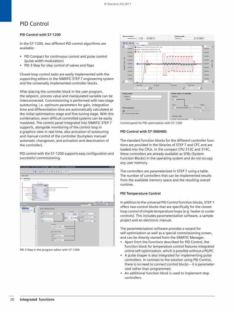
PID Control with S7-1200
In the S7-1200, two different PID control algorithms are available:
• PID Compact for continuous control and pulse control (pulse width modulation)
• PID 3-Step for step control of valves and flaps
Closed-loop control tasks are easily implemented with the supporting editors in the SIMATIC STEP 7 engineering system and the universally implemented controller blocks.
After placing the controller block in the user program, the setpoint, process value and manipulated variable can be interconnected. Commissioning is performed with two-stageautotuning, i.e. optimum parameters for gain, integration time and differentiation time are automatically calculated at the initial optimization stage and fine-tuning stage. With this combination, even difficult controlled systems can be easily mastered. The control panel integrated into SIMATIC STEP 7 supports, alongside monitoring of the control loop in a graphics view in real-time, also activation of autotuning and manual control of the controller (bumpless manual/automatic changeover, and activation and deactivation of the controller).
PID control with the S7-1200 supports easy configuration and successful commissioning.
PID 3-Step in the program editor with S7-1200
Control panel for PID optimization with S7-1200
PID Control with S7-300/400:
The standard function blocks for the different controller func-tions are provided in the libraries of STEP 7 and CFC and are loaded into the CPUs. In the compact CPU 313C and 314C, these controllers are already available as SFBs (System Function Blocks) in the operating system and do not occupy any user memory.
The controllers are parameterized in STEP 7 using a table. The number of controllers that can be implemented results from the available memory space and the resulting overall runtime.
PID Temperature Control
In addition to the universal PID Control function blocks, STEP 7 offers two control blocks that are specifically for the closed-loop control of simple temperature loops (e.g. heater or cooler controls). This includes parameterization software, a sample project and an electronic manual.
The parameterization software provides a wizard for self-optimization as well as a special commissioning screen, and can be directly started from the SIMATIC Manager. • Apart from the functions described for PID Control, the
function block for temperature control features integrated online self-optimization, which is possible without a PG/PC.
• A pulse shaper is also integrated for implementing pulse controllers. In contrast to the solution using PID Control, there is no need to connect control blocks – it is parameter-ized rather than programmed.
• An additional function block is used to implement step controllers.
SIMATIC_Technology_04_2011_en.book Seite 20 Freitag, 25. März 2011 3:51 15
© Siemens AG 2011
Loadable function blocks 21
Loadable function blocksStandard PID Control
Standard PID Control is a preconfigured controller structure that is easily adapted by connecting or disconnecting func-tions to and from the control process. The controller structure is implemented in a function block to be loaded into the CPU. This is graphically configured with the appropriate parameter-ization software. Standard PID Control is implemented wherever small or medium-scale closed-loop control tasks arise: in temperature control, pressure control, flow control as well as fill-level control. Standard PID Control is particularly suited to applications that have been automated with com-pact controllers until now.
Standard PID Control contains the following pre-configured examples:
• Step controllers with line simulation• Continuous-action controller with path simulation• Multi-loop ratio controller• Blending control• Cascade control
Pulse controllers
The pulse controller is combined with the continuous-action controller in the same block, including conversion to a pulse/pause signal (pulse shaper). This simplifies parameter-ization and commissioning of the pulse controller.
It is also possible to adjust the sampling time of the controller and the period duration of the pulse shaper independently. The period duration can therefore be set longer than the sampling time.
• The advantage of a shorter sampling time lies in the rapid response of the controller to faults and operating com-mands.
• The longer period duration, however, protects the final controlling element due to the lower switching frequency. The oscillation of actual values is suppressed because the effective cycle duration is automatically shortened.
• A further advantage is the reduced loading on the CPU because the pulse shaper can be called at less frequent intervals.
• The example provided for a pulse controller with a 3-point output "HEATING - OFF - COOLING" simplifies commission-ing of the temperature control.
Step controllers
An adjustment algorithm ensures that for the same control accuracy, step controllers can have up to 50% fewer switching actions as conventional step controllers. This protects the con-nected actuators and increases their service life considerably.
Extended manual/automatic changeover
The following functions can be selected for manual/automatic changeover by setting parameters:
• Bumpless manual/automatic changeover• Bumpless manual/automatic changeover with a corre-
sponding step change in controller output for faster compensation of the system deviation
• Manual value follow-up in automatic mode
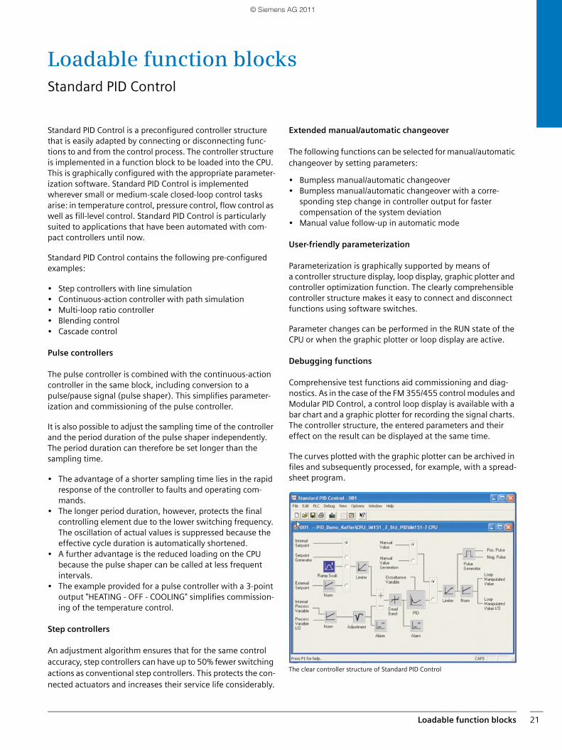
User-friendly parameterization
Parameterization is graphically supported by means of a controller structure display, loop display, graphic plotter and controller optimization function. The clearly comprehensible controller structure makes it easy to connect and disconnect functions using software switches.
Parameter changes can be performed in the RUN state of the CPU or when the graphic plotter or loop display are active.
Debugging functions
Comprehensive test functions aid commissioning and diag-nostics. As in the case of the FM 355/455 control modules and Modular PID Control, a control loop display is available with a bar chart and a graphic plotter for recording the signal charts. The controller structure, the entered parameters and their effect on the result can be displayed at the same time.
The curves plotted with the graphic plotter can be archived in files and subsequently processed, for example, with a spread-sheet program.
The clear controller structure of Standard PID Control
SIMATIC_Technology_04_2011_en.book Seite 21 Freitag, 25. März 2011 3:51 15
© Siemens AG 2011
Loadable function blocks22
PID Self-Tuner
Controller optimization
The parameterization software contains a self-tuning function that can be used to adjust this controller extremely quickly without the need for exact knowledge of the controlled system. For this purpose, the process is activated with a step change in controller output or a setpoint change. During the settling period, the process values are automatically acquired and displayed. The program calculates a mathematical model of the controlled system from the values and determines the most favorable controller parameters for PI and PID controllers according to the optimum value.
There is a choice of two different transient responses for controller self-optimization:
• Response of the control loop with overshoot of up to 10%• Transient response without overshoot
For online self-optimization, the PID Self-Tuner is recommend-ed.
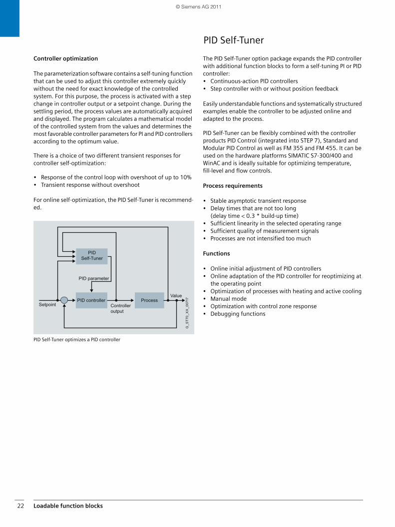
PID Self-Tuner optimizes a PID controller
The PID Self-Tuner option package expands the PID controller with additional function blocks to form a self-tuning PI or PID controller:• Continuous-action PID controllers• Step controller with or without position feedback
Easily understandable functions and systematically structured examples enable the controller to be adjusted online and adapted to the process.
PID Self-Tuner can be flexibly combined with the controller products PID Control (integrated into STEP 7), Standard and Modular PID Control as well as FM 355 and FM 455. It can be used on the hardware platforms SIMATIC S7-300/400 and WinAC and is ideally suitable for optimizing temperature, fill-level and flow controls.
Process requirements
• Stable asymptotic transient response• Delay times that are not too long
(delay time < 0.3 * build-up time)• Sufficient linearity in the selected operating range• Sufficient quality of measurement signals• Processes are not intensified too much
Functions
• Online initial adjustment of PID controllers• Online adaptation of the PID controller for reoptimizing at
the operating point• Optimization of processes with heating and active cooling• Manual mode• Optimization with control zone response• Debugging functions
ValueProcess
Controlleroutput
PID controllerSetpoint
PID parameter
PID Self-Tuner
G_S
T70_
XX
_007
17
SIMATIC_Technology_04_2011_en.book Seite 22 Freitag, 25. März 2011 3:51 15
© Siemens AG 2011
Loadable function blocks 23
Modular PID Control
Modular PID Control is a library of standard function blocks that are optimally tuned to each other.
They can be used to implement any type of controller struc-ture for SIMATIC S7-300/400 and WinAC in process engineer-ing applications. In combination with the SM 334 analog module, sampling times of up to 5 ms are possible.
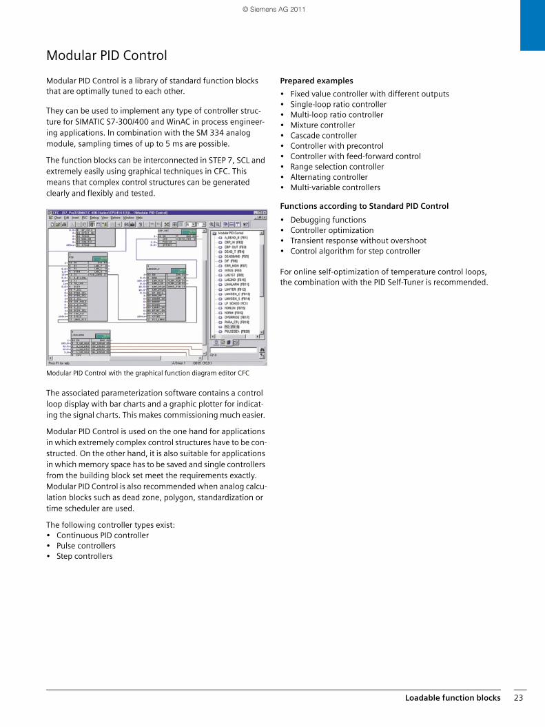
The function blocks can be interconnected in STEP 7, SCL and extremely easily using graphical techniques in CFC. This means that complex control structures can be generated clearly and flexibly and tested.
Modular PID Control with the graphical function diagram editor CFC
The associated parameterization software contains a control loop display with bar charts and a graphic plotter for indicat-ing the signal charts. This makes commissioning much easier.
Modular PID Control is used on the one hand for applications in which extremely complex control structures have to be con-structed. On the other hand, it is also suitable for applications in which memory space has to be saved and single controllers from the building block set meet the requirements exactly. Modular PID Control is also recommended when analog calcu-lation blocks such as dead zone, polygon, standardization or time scheduler are used.
The following controller types exist:• Continuous PID controller• Pulse controllers• Step controllers
Prepared examples
• Fixed value controller with different outputs• Single-loop ratio controller• Multi-loop ratio controller• Mixture controller• Cascade controller• Controller with precontrol• Controller with feed-forward control• Range selection controller• Alternating controller• Multi-variable controllers
Functions according to Standard PID Control
• Debugging functions• Controller optimization• Transient response without overshoot• Control algorithm for step controller
For online self-optimization of temperature control loops, the combination with the PID Self-Tuner is recommended.
SIMATIC_Technology_04_2011_en.book Seite 23 Freitag, 25. März 2011 3:51 15
© Siemens AG 2011
Loadable function blocks24
Easy Motion Control
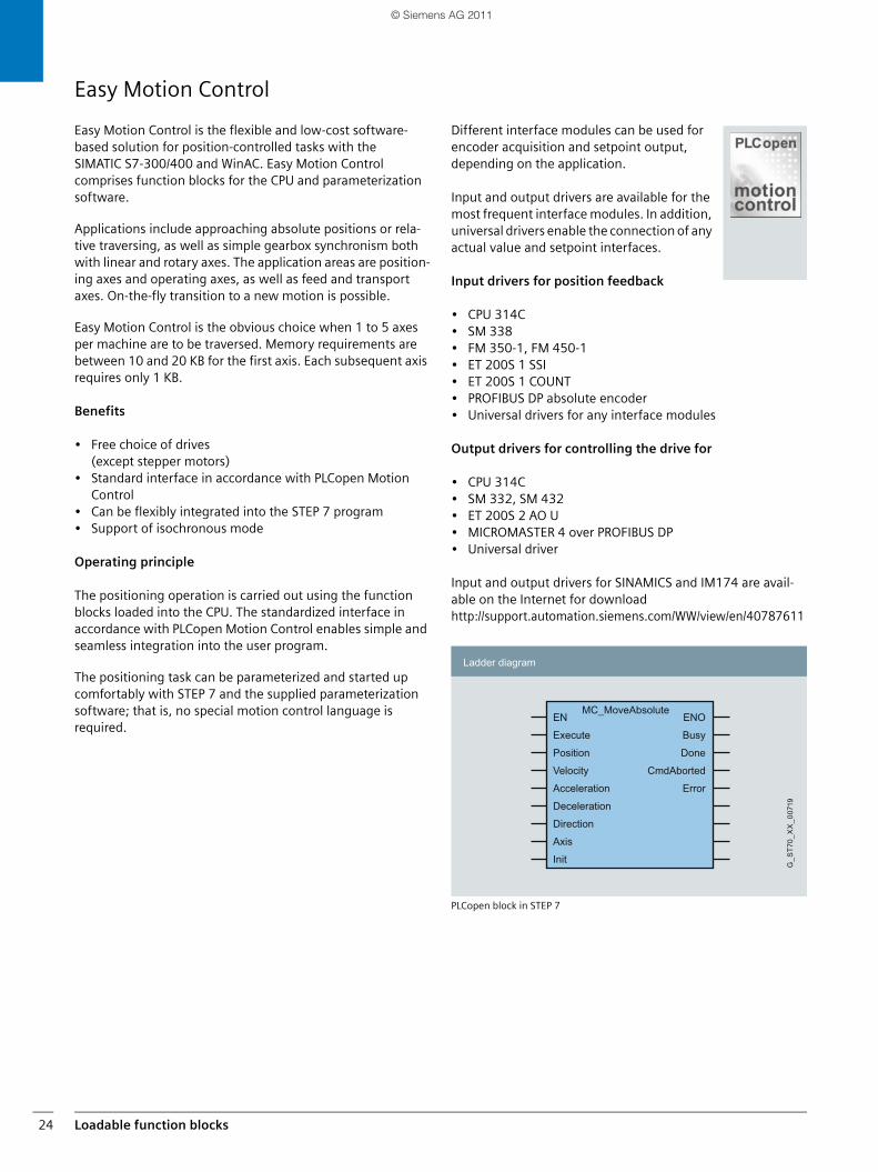
Easy Motion Control is the flexible and low-cost software-based solution for position-controlled tasks with the SIMATIC S7-300/400 and WinAC. Easy Motion Control comprises function blocks for the CPU and parameterization software.
Applications include approaching absolute positions or rela-tive traversing, as well as simple gearbox synchronism both with linear and rotary axes. The application areas are position-ing axes and operating axes, as well as feed and transport axes. On-the-fly transition to a new motion is possible.
Easy Motion Control is the obvious choice when 1 to 5 axes per machine are to be traversed. Memory requirements are between 10 and 20 KB for the first axis. Each subsequent axis requires only 1 KB.
Benefits
• Free choice of drives (except stepper motors)
• Standard interface in accordance with PLCopen Motion Control
• Can be flexibly integrated into the STEP 7 program• Support of isochronous mode
Operating principle
The positioning operation is carried out using the function blocks loaded into the CPU. The standardized interface in accordance with PLCopen Motion Control enables simple and seamless integration into the user program.
The positioning task can be parameterized and started up comfortably with STEP 7 and the supplied parameterization software; that is, no special motion control language is required.
Different interface modules can be used for encoder acquisition and setpoint output, depending on the application.
Input and output drivers are available for the most frequent interface modules. In addition, universal drivers enable the connection of any actual value and setpoint interfaces.
Input drivers for position feedback
• CPU 314C• SM 338• FM 350-1, FM 450-1• ET 200S 1 SSI• ET 200S 1 COUNT• PROFIBUS DP absolute encoder• Universal drivers for any interface modules
Output drivers for controlling the drive for
• CPU 314C• SM 332, SM 432• ET 200S 2 AO U• MICROMASTER 4 over PROFIBUS DP• Universal driver
Input and output drivers for SINAMICS and IM174 are avail-able on the Internet for downloadhttp://support.automation.siemens.com/WW/view/en/40787611
PLCopen block in STEP 7
Ladder diagram
G_S
T70_
XX
_007
19
EN
Execute
Position
Velocity
Acceleration
Deceleration
Direction
Axis
Init
ENO
Busy
Done
CmdAborted
Error
MC_MoveAbsolute
SIMATIC_Technology_04_2011_en.book Seite 24 Freitag, 25. März 2011 3:51 15
© Siemens AG 2011
Distributed ET 200S modules 25
Distributed ET 200S modules
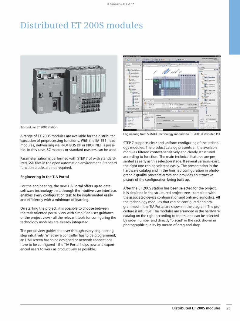
Bit-modular ET 200S station
A range of ET 200S modules are available for the distributed execution of preprocessing functions. With the IM 151 head modules, networking via PROFIBUS DP or PROFINET is possi-ble. In this case, S7 masters or standard masters can be used.
Parameterization is performed with STEP 7 of with standard-ized GSD files in the open automation environment. Standard function blocks are not required.
Engineering in the TIA Portal
For the engineering, the new TIA Portal offers up-to-datesoftware technology that, through the intuitive user interface, enables every configuration task to be implemented easily and efficiently with a minimum of learning.
On starting the project, it is possible to choose betweenthe task-oriented portal view with simplified user guidanceor the project view - all the relevant tools for configuring the technology modules are already integrated.
The portal view guides the user through every engineering step intuitively. Whether a controller has to be programmed, an HMI screen has to be designed or network connections have to be configured - the TIA Portal helps new and experi-enced users to work as productively as possible.
Engineering from SIMATIC technology modules to ET 200S distributed I/O
STEP 7 supports clear and uniform configuring of the technol-ogy modules. The product catalog presents all the available modules filtered context-sensitively and clearly structured according to function. The main technical features are pre-sented as early as this selection stage. If several versions exist, the right one can be selected easily. The presentation in the hardware catalog and in the finished configuration in photo-graphic quality prevents errors and provides an attractive picture of the configuration being built up.
After the ET 200S station has been selected for the project, it is depicted in the structured project tree - complete with the associated device configuration and online diagnostics. All the technology modules that can be configured and pro-grammed in the TIA Portal are shown in the diagram. The pro-cedure is intuitive: The modules are arranged in the hardware catalog on the right according to topics, and can be selected by order number and directly "placed" in the rack shown in photographic quality by means of drag-and-drop.
SIMATIC_Technology_04_2011_en.book Seite 25 Freitag, 25. März 2011 3:51 15
© Siemens AG 2011
Distributed ET 200S modules26
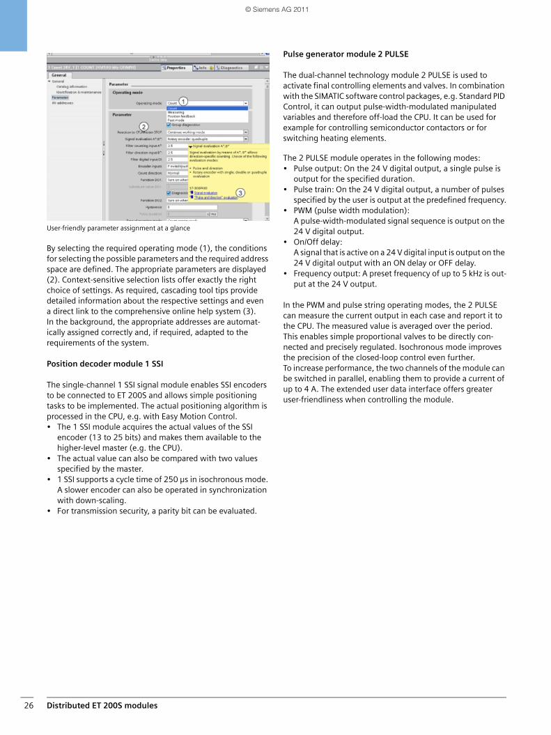
User-friendly parameter assignment at a glance
By selecting the required operating mode (1), the conditions for selecting the possible parameters and the required address space are defined. The appropriate parameters are displayed (2). Context-sensitive selection lists offer exactly the right choice of settings. As required, cascading tool tips provide detailed information about the respective settings and evena direct link to the comprehensive online help system (3). In the background, the appropriate addresses are automat-ically assigned correctly and, if required, adapted to the requirements of the system.
Position decoder module 1 SSI
The single-channel 1 SSI signal module enables SSI encoders to be connected to ET 200S and allows simple positioning tasks to be implemented. The actual positioning algorithm is processed in the CPU, e.g. with Easy Motion Control.• The 1 SSI module acquires the actual values of the SSI
encoder (13 to 25 bits) and makes them available to the higher-level master (e.g. the CPU).
• The actual value can also be compared with two values specified by the master.
• 1 SSI supports a cycle time of 250 µs in isochronous mode. A slower encoder can also be operated in synchronization with down-scaling.
• For transmission security, a parity bit can be evaluated.
Pulse generator module 2 PULSE
The dual-channel technology module 2 PULSE is used to activate final controlling elements and valves. In combination with the SIMATIC software control packages, e.g. Standard PID Control, it can output pulse-width-modulated manipulated variables and therefore off-load the CPU. It can be used for example for controlling semiconductor contactors or for switching heating elements.
The 2 PULSE module operates in the following modes:• Pulse output: On the 24 V digital output, a single pulse is
output for the specified duration.• Pulse train: On the 24 V digital output, a number of pulses
specified by the user is output at the predefined frequency.• PWM (pulse width modulation):
A pulse-width-modulated signal sequence is output on the 24 V digital output.
• On/Off delay: A signal that is active on a 24 V digital input is output on the 24 V digital output with an ON delay or OFF delay.
• Frequency output: A preset frequency of up to 5 kHz is out-put at the 24 V output.
In the PWM and pulse string operating modes, the 2 PULSE can measure the current output in each case and report it to the CPU. The measured value is averaged over the period. This enables simple proportional valves to be directly con-nected and precisely regulated. Isochronous mode improves the precision of the closed-loop control even further. To increase performance, the two channels of the module can be switched in parallel, enabling them to provide a current of up to 4 A. The extended user data interface offers greater user-friendliness when controlling the module.
SIMATIC_Technology_04_2011_en.book Seite 26 Freitag, 25. März 2011 3:51 15
© Siemens AG 2011
Distributed ET 200S modules 27
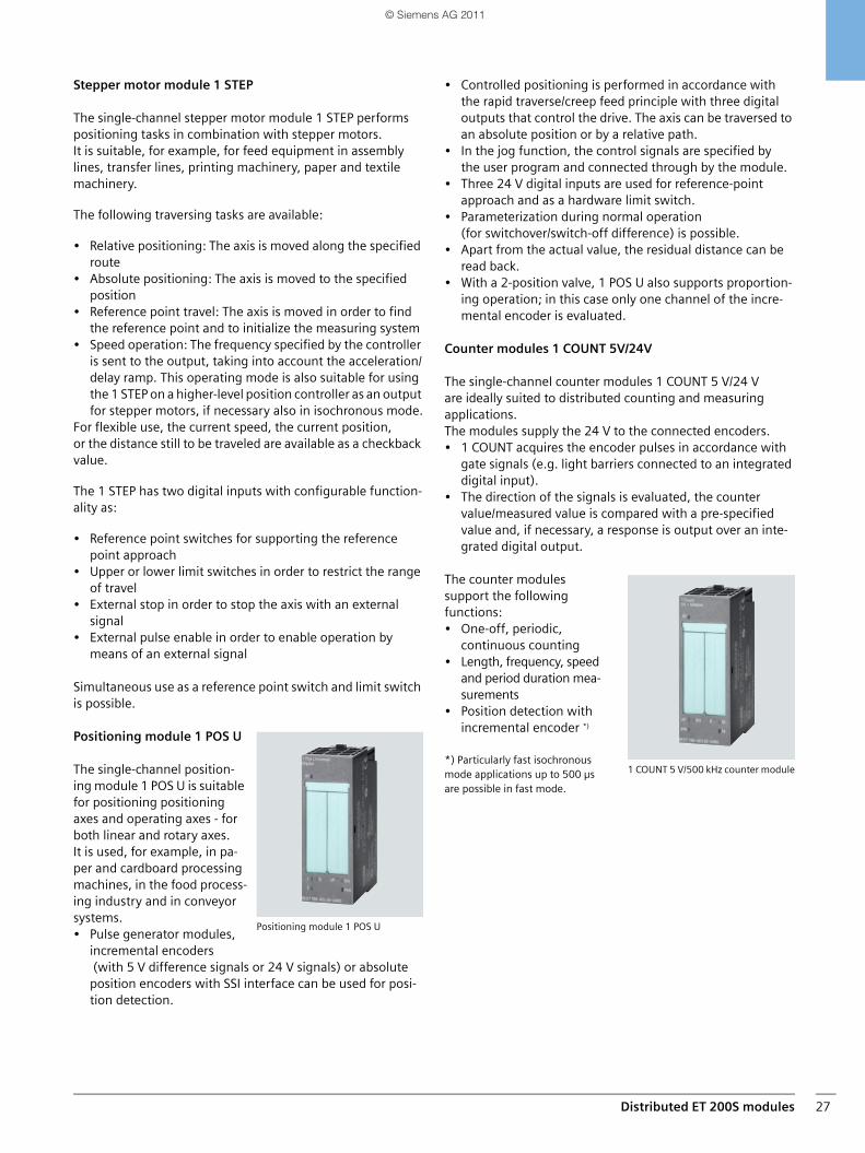
Stepper motor module 1 STEP
The single-channel stepper motor module 1 STEP performs positioning tasks in combination with stepper motors. It is suitable, for example, for feed equipment in assembly lines, transfer lines, printing machinery, paper and textile machinery.
The following traversing tasks are available:
• Relative positioning: The axis is moved along the specified route
• Absolute positioning: The axis is moved to the specified position
• Reference point travel: The axis is moved in order to find the reference point and to initialize the measuring system
• Speed operation: The frequency specified by the controller is sent to the output, taking into account the acceleration/delay ramp. This operating mode is also suitable for using the 1 STEP on a higher-level position controller as an output for stepper motors, if necessary also in isochronous mode.
For flexible use, the current speed, the current position, or the distance still to be traveled are available as a checkback value.
The 1 STEP has two digital inputs with configurable function-ality as:
• Reference point switches for supporting the reference point approach
• Upper or lower limit switches in order to restrict the range of travel
• External stop in order to stop the axis with an externalsignal
• External pulse enable in order to enable operation by means of an external signal
Simultaneous use as a reference point switch and limit switch is possible.
Positioning module 1 POS U
The single-channel position-ing module 1 POS U is suitable for positioning positioning axes and operating axes - for both linear and rotary axes.It is used, for example, in pa-per and cardboard processing machines, in the food process-ing industry and in conveyor systems. • Pulse generator modules,
incremental encoders (with 5 V difference signals or 24 V signals) or absolute position encoders with SSI interface can be used for posi-tion detection.
• Controlled positioning is performed in accordance with the rapid traverse/creep feed principle with three digital outputs that control the drive. The axis can be traversed to an absolute position or by a relative path.
• In the jog function, the control signals are specified by the user program and connected through by the module.
• Three 24 V digital inputs are used for reference-point approach and as a hardware limit switch.
• Parameterization during normal operation (for switchover/switch-off difference) is possible.
• Apart from the actual value, the residual distance can be read back.
• With a 2-position valve, 1 POS U also supports proportion-ing operation; in this case only one channel of the incre-mental encoder is evaluated.
Counter modules 1 COUNT 5V/24V
The single-channel counter modules 1 COUNT 5 V/24 V are ideally suited to distributed counting and measuring applications. The modules supply the 24 V to the connected encoders.• 1 COUNT acquires the encoder pulses in accordance with
gate signals (e.g. light barriers connected to an integrated digital input).
• The direction of the signals is evaluated, the counter value/measured value is compared with a pre-specified value and, if necessary, a response is output over an inte-grated digital output.
The counter modules support the following functions:• One-off, periodic,
continuous counting• Length, frequency, speed
and period duration mea-surements
• Position detection with incremental encoder *)
*) Particularly fast isochronous mode applications up to 500 µs are possible in fast mode.
Positioning module 1 POS U
1 COUNT 5 V/500 kHz counter module
SIMATIC_Technology_04_2011_en.book Seite 27 Freitag, 25. März 2011 3:51 15
© Siemens AG 2011
Parameterizable function modules28
Parameterizable function modules
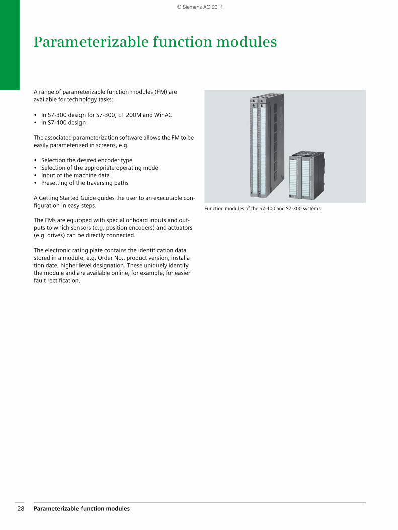
A range of parameterizable function modules (FM) are available for technology tasks:
• In S7-300 design for S7-300, ET 200M and WinAC • In S7-400 design
The associated parameterization software allows the FM to be easily parameterized in screens, e.g.
• Selection the desired encoder type• Selection of the appropriate operating mode• Input of the machine data• Presetting of the traversing paths
A Getting Started Guide guides the user to an executable con-figuration in easy steps.
The FMs are equipped with special onboard inputs and out-puts to which sensors (e.g. position encoders) and actuators (e.g. drives) can be directly connected.
The electronic rating plate contains the identification data stored in a module, e.g. Order No., product version, installa-tion date, higher level designation. These uniquely identify the module and are available online, for example, for easier fault rectification.
Function modules of the S7-400 and S7-300 systems
SIMATIC_Technology_04_2011_en.book Seite 28 Freitag, 25. März 2011 3:51 15
© Siemens AG 2011
Parameterizable function modules 29
Counter modules Cam controllers
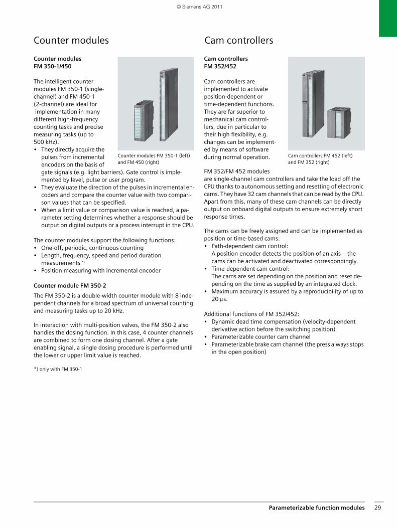
Counter modulesFM 350-1/450
The intelligent counter modules FM 350-1 (single-channel) and FM 450-1 (2-channel) are ideal for implementation in many different high-frequency counting tasks and precise measuring tasks (up to 500 kHz). • They directly acquire the
pulses from incremental encoders on the basis of gate signals (e.g. light barriers). Gate control is imple-mented by level, pulse or user program.
• They evaluate the direction of the pulses in incremental en-coders and compare the counter value with two compari-son values that can be specified.
• When a limit value or comparison value is reached, a pa-rameter setting determines whether a response should be output on digital outputs or a process interrupt in the CPU.
The counter modules support the following functions:• One-off, periodic, continuous counting• Length, frequency, speed and period duration
measurements *)
• Position measuring with incremental encoder
Counter module FM 350-2
The FM 350-2 is a double-width counter module with 8 inde-pendent channels for a broad spectrum of universal counting and measuring tasks up to 20 kHz.
In interaction with multi-position valves, the FM 350-2 also handles the dosing function. In this case, 4 counter channels are combined to form one dosing channel. After a gate enabling signal, a single dosing procedure is performed until the lower or upper limit value is reached.
*) only with FM 350-1
Cam controllers FM 352/452
Cam controllers are implemented to activate position-dependent or time-dependent functions. They are far superior to mechanical cam control-lers, due in particular to their high flexibility, e.g. changes can be implement-ed by means of software during normal operation.
FM 352/FM 452 modules are single-channel cam controllers and take the load off the CPU thanks to autonomous setting and resetting of electronic cams. They have 32 cam channels that can be read by the CPU. Apart from this, many of these cam channels can be directly output on onboard digital outputs to ensure extremely short response times.
The cams can be freely assigned and can be implemented as position or time-based cams: • Path-dependent cam control:
A position encoder detects the position of an axis – the cams can be activated and deactivated correspondingly.
• Time-dependent cam control: The cams are set depending on the position and reset de-pending on the time as supplied by an integrated clock.
• Maximum accuracy is assured by a reproducibility of up to 20 μs.
Additional functions of FM 352/452:• Dynamic dead time compensation (velocity-dependent
derivative action before the switching position)• Parameterizable counter cam channel• Parameterizable brake cam channel (the press always stops
in the open position)
Counter modules FM 350-1 (left) and FM 450 (right)
Cam controllers FM 452 (left) and FM 352 (right)
SIMATIC_Technology_04_2011_en.book Seite 29 Freitag, 25. März 2011 3:51 15
© Siemens AG 2011
Parameterizable function modules30
Control modules
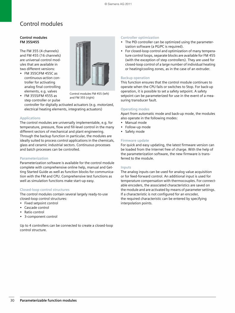
Control modules FM 355/455
The FM 355 (4 channels) and FM 455 (16 channels) are universal control mod-ules that are available in two different versions:• FM 355C/FM 455C as
continuous-action con-troller for activating analog final controlling elements, e.g. valves
• FM 355S/FM 455S as step controller or pulse controller for digitally activated actuators (e.g. motorized, electrical heating elements, integrating actuators)
ApplicationsThe control modules are universally implementable, e.g. for temperature, pressure, flow and fill-level control in the many different sectors of mechanical and plant engineering. Through the backup function in particular, the modules are ideally suited to process control applications in the chemicals, glass and ceramic industrial sectors. Continuous processes and batch processes can be controlled.
ParameterizationParameterization software is available for the control module complete with comprehensive online help, manual and Get-ting Started Guide as well as function blocks for communica-tion with the FM and CPU. Comprehensive test functions as well as simulation functions make start-up easy.
Closed-loop control structuresThe control modules contain several largely ready-to-use closed-loop control structures:• Fixed setpoint control• Cascade control• Ratio control• 3-component control
Up to 4 controllers can be connected to create a closed-loop control structure.
Controller optimization• The PID controller can be optimized using the parameter-
ization software (a PG/PC is required).• For closed-loop control and optimization of many tempera-
ture control loops, separate blocks are available for FM 455 (with the exception of step controllers). They are used for closed-loop control of a large number of individual heating or heating/cooling zones, as in the case of an extruder.
Backup operationThis function ensures that the control module continues to operate when the CPU fails or switches to Stop. For back-up operation, it is possible to set a safety setpoint. A safety setpoint can be parameterized for use in the event of a mea-suring transducer fault.
Operating modesApart from automatic mode and back-up mode, the modules also operate in the following modes:• Manual mode• Follow-up mode• Safety mode
Firmware updateFor quick and easy updating, the latest firmware version can be loaded from the Internet free of charge. With the help of the parameterization software, the new firmware is trans-ferred to the module.
InputsThe analog inputs can be used for analog value acquisition or for feed-forward control. An additional input is used for temperature compensation with thermocouples. For connect-able encoders, the associated characteristics are saved on the module and are activated by means of parameter settings. If a characteristic is not configured for an encoder, the required characteristic can be entered by specifying interpolation points.
Control modules FM 455 (left) and FM 355 (right)
SIMATIC_Technology_04_2011_en.book Seite 30 Freitag, 25. März 2011 3:51 15
© Siemens AG 2011
Parameterizable function modules 31
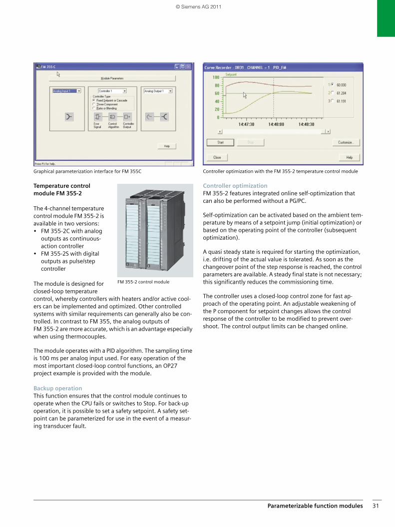
Graphical parameterization interface for FM 355C
Temperature control module FM 355-2
The 4-channel temperature control module FM 355-2 is available in two versions: • FM 355-2C with analog
outputs as continuous-action controller
• FM 355-2S with digital outputs as pulse/step controller
The module is designed for closed-loop temperature control, whereby controllers with heaters and/or active cool-ers can be implemented and optimized. Other controlled systems with similar requirements can generally also be con-trolled. In contrast to FM 355, the analog outputs of FM 355-2 are more accurate, which is an advantage especially when using thermocouples.
The module operates with a PID algorithm. The sampling time is 100 ms per analog input used. For easy operation of the most important closed-loop control functions, an OP27 project example is provided with the module.
Backup operationThis function ensures that the control module continues to operate when the CPU fails or switches to Stop. For back-up operation, it is possible to set a safety setpoint. A safety set-point can be parameterized for use in the event of a measur-ing transducer fault.
Controller optimization with the FM 355-2 temperature control module
Controller optimizationFM 355-2 features integrated online self-optimization that can also be performed without a PG/PC.
Self-optimization can be activated based on the ambient tem-perature by means of a setpoint jump (initial optimization) or based on the operating point of the controller (subsequent optimization).
A quasi steady state is required for starting the optimization, i.e. drifting of the actual value is tolerated. As soon as the changeover point of the step response is reached, the control parameters are available. A steady final state is not necessary; this significantly reduces the commissioning time.
The controller uses a closed-loop control zone for fast ap-proach of the operating point. An adjustable weakening of the P component for setpoint changes allows the control response of the controller to be modified to prevent over-shoot. The control output limits can be changed online.
FM 355-2 control module
SIMATIC_Technology_04_2011_en.book Seite 31 Freitag, 25. März 2011 3:51 15
© Siemens AG 2011
Parameterizable function modules32
Positioning modules
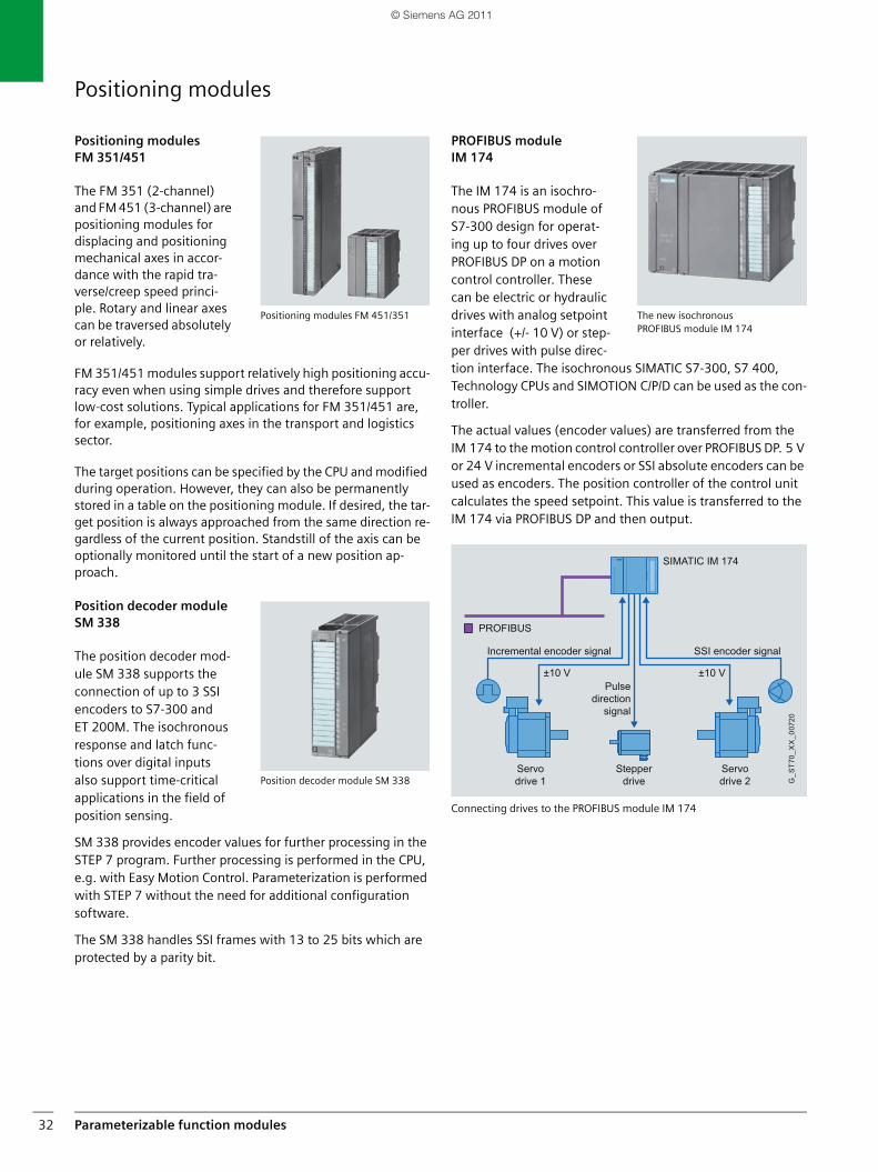
Positioning modulesFM 351/451
The FM 351 (2-channel) and FM 451 (3-channel) are positioning modules for displacing and positioning mechanical axes in accor-dance with the rapid tra-verse/creep speed princi-ple. Rotary and linear axes can be traversed absolutely or relatively.
FM 351/451 modules support relatively high positioning accu-racy even when using simple drives and therefore support low-cost solutions. Typical applications for FM 351/451 are, for example, positioning axes in the transport and logistics sector.
The target positions can be specified by the CPU and modified during operation. However, they can also be permanently stored in a table on the positioning module. If desired, the tar-get position is always approached from the same direction re-gardless of the current position. Standstill of the axis can be optionally monitored until the start of a new position ap-proach.
Position decoder module SM 338
The position decoder mod-ule SM 338 supports the connection of up to 3 SSI encoders to S7-300 and ET 200M. The isochronous response and latch func-tions over digital inputs also support time-critical applications in the field of position sensing.
SM 338 provides encoder values for further processing in the STEP 7 program. Further processing is performed in the CPU, e.g. with Easy Motion Control. Parameterization is performed with STEP 7 without the need for additional configuration software.
The SM 338 handles SSI frames with 13 to 25 bits which are protected by a parity bit.
PROFIBUS module IM 174
The IM 174 is an isochro-nous PROFIBUS module of S7-300 design for operat-ing up to four drives over PROFIBUS DP on a motion control controller. These can be electric or hydraulic drives with analog setpoint interface (+/- 10 V) or step-per drives with pulse direc-tion interface. The isochronous SIMATIC S7-300, S7 400, Technology CPUs and SIMOTION C/P/D can be used as the con-troller.
The actual values (encoder values) are transferred from the IM 174 to the motion control controller over PROFIBUS DP. 5 V or 24 V incremental encoders or SSI absolute encoders can be used as encoders. The position controller of the control unit calculates the speed setpoint. This value is transferred to the IM 174 via PROFIBUS DP and then output.
Connecting drives to the PROFIBUS module IM 174
Positioning modules FM 451/351
Position decoder module SM 338
The new isochronous PROFIBUS module IM 174
SSI encoder signalIncremental encoder signal
Servo drive 2
Servo drive 1
Pulsedirection
signal
Stepper drive
PROFIBUS
SIMATIC IM 174
±10 V±10 V
G_S
T70_
XX
_007
20
SIMATIC_Technology_04_2011_en.book Seite 32 Freitag, 25. März 2011 3:51 15
© Siemens AG 2011
Parameterizable function modules 33
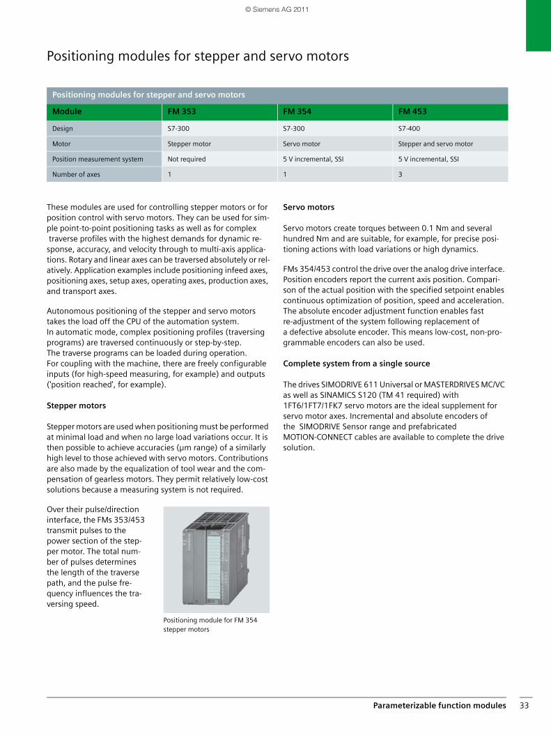
Positioning modules for stepper and servo motors
These modules are used for controlling stepper motors or for position control with servo motors. They can be used for sim-ple point-to-point positioning tasks as well as for complex traverse profiles with the highest demands for dynamic re-sponse, accuracy, and velocity through to multi-axis applica-tions. Rotary and linear axes can be traversed absolutely or rel-atively. Application examples include positioning infeed axes, positioning axes, setup axes, operating axes, production axes, and transport axes.
Autonomous positioning of the stepper and servo motors takes the load off the CPU of the automation system. In automatic mode, complex positioning profiles (traversing programs) are traversed continuously or step-by-step. The traverse programs can be loaded during operation. For coupling with the machine, there are freely configurable inputs (for high-speed measuring, for example) and outputs ('position reached', for example).
Stepper motors
Stepper motors are used when positioning must be performed at minimal load and when no large load variations occur. It is then possible to achieve accuracies (µm range) of a similarly high level to those achieved with servo motors. Contributions are also made by the equalization of tool wear and the com-pensation of gearless motors. They permit relatively low-cost solutions because a measuring system is not required.
Over their pulse/direction interface, the FMs 353/453 transmit pulses to the power section of the step-per motor. The total num-ber of pulses determines the length of the traverse path, and the pulse fre-quency influences the tra-versing speed.
Servo motors
Servo motors create torques between 0.1 Nm and several hundred Nm and are suitable, for example, for precise posi-tioning actions with load variations or high dynamics.
FMs 354/453 control the drive over the analog drive interface. Position encoders report the current axis position. Compari-son of the actual position with the specified setpoint enables continuous optimization of position, speed and acceleration. The absolute encoder adjustment function enables fast re-adjustment of the system following replacement of a defective absolute encoder. This means low-cost, non-pro-grammable encoders can also be used.
Complete system from a single source
The drives SIMODRIVE 611 Universal or MASTERDRIVES MC/VC as well as SINAMICS S120 (TM 41 required) with 1FT6/1FT7/1FK7 servo motors are the ideal supplement for servo motor axes. Incremental and absolute encoders of the SIMODRIVE Sensor range and prefabricated MOTION-CONNECT cables are available to complete the drive solution.
Positioning modules for stepper and servo motors
Module FM 353 FM 354 FM 453
Design S7-300 S7-300 S7-400
Motor Stepper motor Servo motor Stepper and servo motor
Position measurement system Not required 5 V incremental, SSI 5 V incremental, SSI
Number of axes 1 1 3
Positioning module for FM 354 stepper motors
SIMATIC_Technology_04_2011_en.book Seite 33 Freitag, 25. März 2011 3:51 15
© Siemens AG 2011
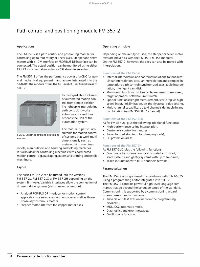
Parameterizable function modules34
Path control and positioning module FM 357-2
Applications
The FM 357-2 is a path control and positioning module for controlling up to four rotary or linear axes. Stepper and servo motors with ± 10 V interface or PROFIBUS DP interface can be connected. The actual position can be monitored using either RS 422 incremental encoders or SSI absolute encoders.
The FM 357-2 offers the performance power of a CNC for gen-eral mechanical equipment manufacture. Integrated into the SIMATIC, the module offers the full level of user friendliness of STEP 7.
It covers just about all areas of automated motion con-trol from simple position-ing right up to interpolating path control. It works autonomously and thus offloads the CPU of the automation system.
The module is particularly suitable for motion control of systems that work multi-dimensionally such as metalworking machines,
robots, manipulators and bending and folding machines. It is also ideal for controlling machines with coordinatedmotion control, e.g. packaging, paper, and printing and textile machinery.
Layout
The basic FM 357-2 can be turned into the versionsFM 357-2L, FM 357-2LX or FM 357-2H depending on the system firmware. Variable interfaces allow the connection of different drive systems (also in mixed operation):
• Analog/PROFIBUS DP interface for motion control applications or servo axes with encoder as well as three-phase asynchronous motors
• Stepper motor interface for stepper motor axes
Operating principle
Depending on the axis type used, the stepper or servo motor axes are moved as with the FM 353/FM 354 modules. On the FM 357-2, however, the axes can also be moved with interpolation.
Functions of the FM 357-2L• Internal interpolation and coordination of one to four axes:
Linear interpolation, circular interpolation and complex in-terpolation; path control; synchronized axes; table interpo-lation; intelligent cam disk.
• Monitoring functions: broken cable, zero mark, zero speed, target approach, software limit switch.
• Special functions: length measurement, start/stop via high-speed input, jerk limitation, on-the-fly actual value setting.
• Multi-channel capability: up to 4 channels definable in any combination (on FM 357-2H: 1 channel).
Functions of the FM 357-2LXAs for FM 357-2L, plus the following additional functions:• High-performance spline interpolation,• Gantry axis control for gantries,• Travel to fixed stop (e.g. for clamping tools),• 3D protection areas.
Functions of the FM 357-2HAs FM 357-2LX, plus the following functions:• Coordinate transformation for articulated arm robot,
scara systems and gantry systems with up to four axes;• Teach-in function with HT 6 handheld terminal.
Parameterization
The FM 357-2 is programmed in accordance with DIN 66025 using a programming editor integrated into STEP 7. The FM 357-2 contains powerful high-level-language com-mands that go beyond the language scope of the standard. Commissioning is supported by a commissioning wizard offering user-friendly functions:• Traverse and test axes online from the programming
device/PC,• MDI, JOG, automatic mode,• Diagnostics and error messages,• Oscilloscope function.
FM 357-2 path control and positioning module
SIMATIC_Technology_04_2011_en.book Seite 34 Freitag, 25. März 2011 3:51 15
© Siemens AG 2011
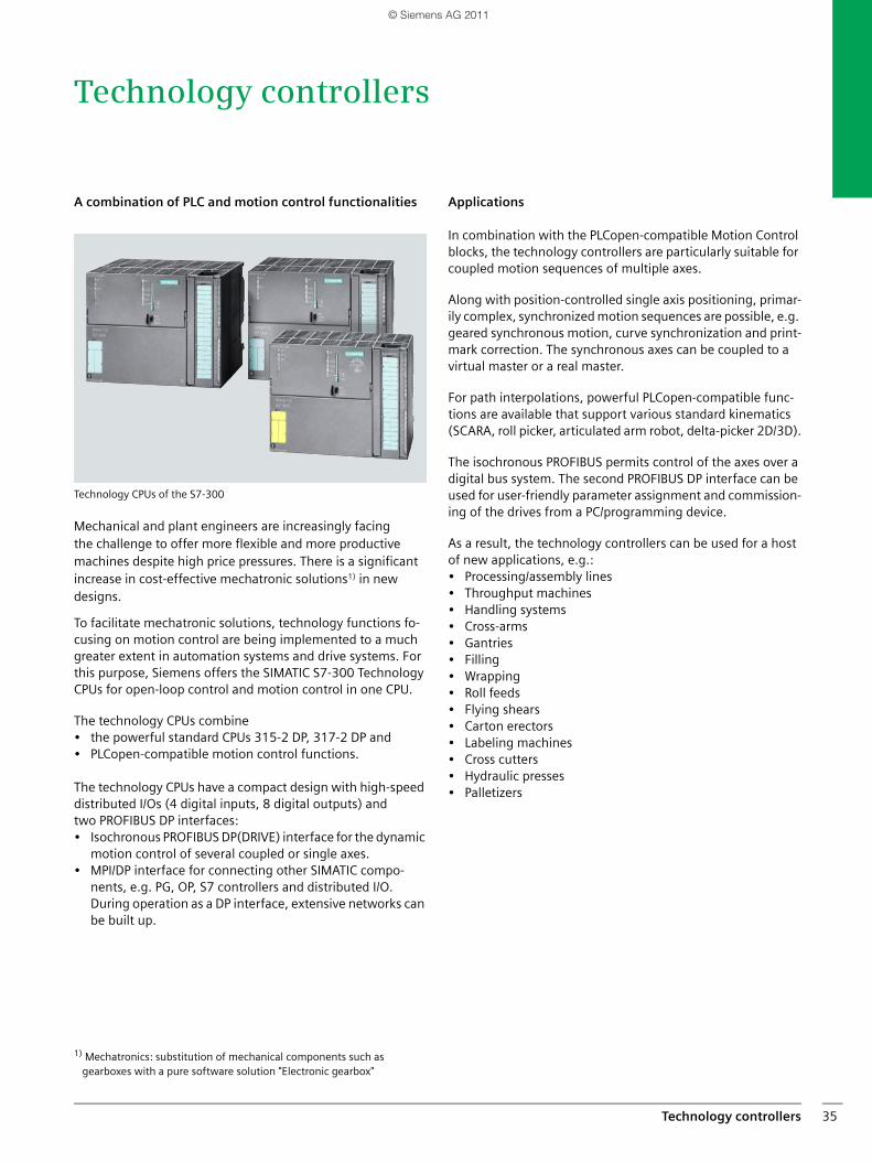
Technology controllers 35
Technology controllers
A combination of PLC and motion control functionalities
Technology CPUs of the S7-300
Mechanical and plant engineers are increasingly facing the challenge to offer more flexible and more productive machines despite high price pressures. There is a significant increase in cost-effective mechatronic solutions1) in new designs.
To facilitate mechatronic solutions, technology functions fo-cusing on motion control are being implemented to a much greater extent in automation systems and drive systems. For this purpose, Siemens offers the SIMATIC S7-300 Technology CPUs for open-loop control and motion control in one CPU.
The technology CPUs combine• the powerful standard CPUs 315-2 DP, 317-2 DP and• PLCopen-compatible motion control functions.
The technology CPUs have a compact design with high-speed distributed I/Os (4 digital inputs, 8 digital outputs) and two PROFIBUS DP interfaces:• Isochronous PROFIBUS DP(DRIVE) interface for the dynamic
motion control of several coupled or single axes.• MPI/DP interface for connecting other SIMATIC compo-
nents, e.g. PG, OP, S7 controllers and distributed I/O. During operation as a DP interface, extensive networks can be built up.
1) Mechatronics: substitution of mechanical components such as gearboxes with a pure software solution "Electronic gearbox"
Applications
In combination with the PLCopen-compatible Motion Control blocks, the technology controllers are particularly suitable for coupled motion sequences of multiple axes.
Along with position-controlled single axis positioning, primar-ily complex, synchronized motion sequences are possible, e.g. geared synchronous motion, curve synchronization and print-mark correction. The synchronous axes can be coupled to a virtual master or a real master.
For path interpolations, powerful PLCopen-compatible func-tions are available that support various standard kinematics (SCARA, roll picker, articulated arm robot, delta-picker 2D/3D).
The isochronous PROFIBUS permits control of the axes over a digital bus system. The second PROFIBUS DP interface can be used for user-friendly parameter assignment and commission-ing of the drives from a PC/programming device.
As a result, the technology controllers can be used for a host of new applications, e.g.:• Processing/assembly lines• Throughput machines• Handling systems• Cross-arms• Gantries• Filling• Wrapping• Roll feeds• Flying shears• Carton erectors• Labeling machines• Cross cutters• Hydraulic presses• Palletizers
SIMATIC_Technology_04_2011_en.book Seite 35 Freitag, 25. März 2011 3:51 15
© Siemens AG 2011
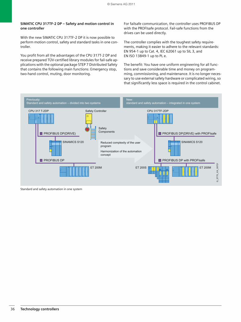
Technology controllers36
SIMATIC CPU 317TF-2 DP – Safety and motion control in one controller
With the new SIMATIC CPU 317TF-2 DP it is now possible to perform motion control, safety and standard tasks in one con-troller.
You profit from all the advantages of the CPU 317T-2 DP and receive prepared TÜV-certified library modules for fail-safe ap-plications with the optional package STEP 7 Distributed Safety that contains the following main functions: Emergency stop, two-hand control, muting, door monitoring.
For failsafe communication, the controller uses PROFIBUS DP with the PROFIsafe protocol. Fail-safe functions from the drives can be used directly.
The controller complies with the toughest safety require-ments, making it easier to adhere to the relevant standards: EN 954-1 up to Cat. 4, IEC 62061 up to SIL 3, and EN ISO 13849-1 up to PL e.
The benefit: You have one uniform engineering for all func-tions and save considerable time and money on program-ming, commissioning, and maintenance. It is no longer neces-sary to use external safety hardware or complicated wiring, so that significantly less space is required in the control cabinet.
Standard and safety automation in one system
New: standard and safety automation – integrated in one system
Previously: Standard and safety automation – divided into two systems
Reduced complexity of the user program
Harmonization of the automation concept
Safety Components
G_S
T70_
XX
_007
21
SINAMICS S120
CPU 317 T-2DP CPU 317TF-2DP
ET 200SET 200M ET 200M
SINAMICS S120
Safety Controller
SIMATIC_Technology_04_2011_en.book Seite 36 Freitag, 25. März 2011 3:51 15
© Siemens AG 2011
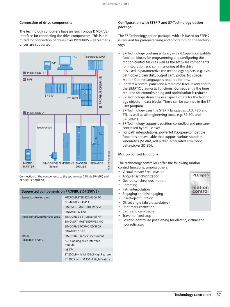
Technology controllers 37
Connection of drive components
The technology controllers have an isochronous DP(DRIVE) interface for connecting the drive components. This is opti-mized for connection of drives over PROFIBUS – all Siemens drives are supported.
Connection of the components to the technology CPU via DP(MPI) and PROFIBUS DP(DRIVE)
Configuration with STEP 7 and S7-Technology option package
The S7-Technology option package, which is based on STEP 7, is required for parameterizing and programming the technol-ogy:
• S7-Technology contains a library with PLCopen-compatible function blocks for programming and configuring the motion control tasks as well as the software components for integration and commissioning of the drive.
• It is used to parameterize the technology objects, e.g. axis, path object, cam disk, output cam, probe. No special Motion Control language is required for this.
• It offers a control panel and a real-time trace in addition to the SIMATIC diagnostic functions. Consequently the time required for commissioning and optimization is reduced.
• S7-Technology stores the user-specific data for the technol-ogy objects in data blocks. These can be scanned in the S7 user program.
• S7-Technology uses the STEP 7 languages LAD, FBD and STL as well as all engineering tools, e.g. S7-SCL and S7-GRAPH.
• S7-Technology supports position-controlled and pressure-controlled hydraulic axes.
• For path interpolations, powerful PLCopen-compatible functions are available that support various standard kinematics (SCARA, roll picker, articulated arm robot, delta-picker 2D/3D).
Motion control functions
The technology controllers offer the following motion control functions, among others:• Virtual master / real master• Angular synchronization• Geared synchronous motion• Camming• Path interpolation• Engaging and disengaging• Insert/eject function• Offset angle (absolute/relative)• Print mark correction• Cams and cam tracks• Travel to fixed stop• Position-controlled positioning for electric, virtual and
hydraulic axes
Supported components on PROFIBUS DP(DRIVE)
Speed-controlled axes MICROMASTER 420/430/440
COMBIMASTER 411
SIMOVERT MASTERDRIVES VC
SINAMICS G 120
Positioning/synchronized axes SIMODRIVE 611 universal HR
SIMOVERT MASTERDRIVES MC
SIMODRIVE POSMO CD/SI/CA
SINAMICS S 120
Other PROFIBUS nodes
SIMODRIVE sensor isochronous
ADI 4 analog drive interface module
IM 174
ET 200M with IM 153-2 High Feature
ET 200S with IM 151-1 High Feature
G_S
T70_
XX
_007
22
SIMATIC_Technology_04_2011_en.book Seite 37 Freitag, 25. März 2011 3:51 15
© Siemens AG 2011
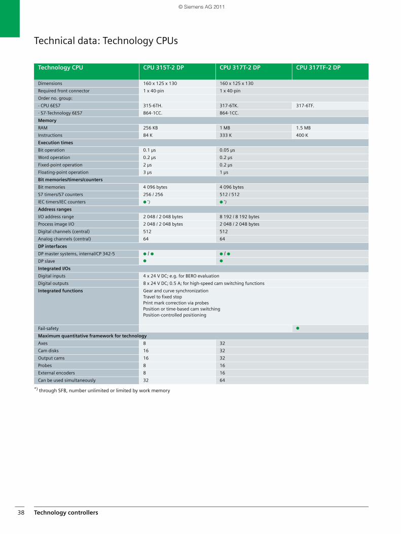
Technology controllers38
Technical data: Technology CPUs
*) through SFB, number unlimited or limited by work memory
Technology CPU CPU 315T-2 DP CPU 317T-2 DP CPU 317TF-2 DP
Dimensions 160 x 125 x 130 160 x 125 x 130
Required front connector 1 x 40-pin 1 x 40-pin
Order no. group:
- CPU 6ES7 315-6TH. 317-6TK. 317-6TF.
- S7-Technology 6ES7 864-1CC. 864-1CC.
Memory
RAM 256 KB 1 MB 1.5 MB
Instructions 84 K 333 K 400 K
Execution times
Bit operation 0.1 µs 0.05 µs
Word operation 0.2 µs 0.2 µs
Fixed-point operation 2 µs 0.2 µs
Floating-point operation 3 µs 1 µs
Bit memories/timers/counters
Bit memories 4 096 bytes 4 096 bytes
S7 timers/S7 counters 256 / 256 512 / 512
IEC timers/IEC counters ● *) ● *)
Address ranges
I/O address range 2 048 / 2 048 bytes 8 192 / 8 192 bytes
Process image I/O 2 048 / 2 048 bytes 2 048 / 2 048 bytes
Digital channels (central) 512 512
Analog channels (central) 64 64
DP interfaces
DP master systems, internal/CP 342-5 ● / ● ● / ●DP slave ● ●
Integrated I/Os
Digital inputs 4 x 24 V DC; e.g. for BERO evaluation
Digital outputs 8 x 24 V DC; 0.5 A; for high-speed cam switching functions
Integrated functions Gear and curve synchronizationTravel to fixed stopPrint mark correction via probesPosition or time-based cam switchingPosition-controlled positioning
Fail-safety ●
Maximum quantitative framework for technology
Axes 8 32
Cam disks 16 32
Output cams 16 32
Probes 8 16
External encoders 8 16
Can be used simultaneously 32 64
SIMATIC_Technology_04_2011_en.book Seite 38 Freitag, 25. März 2011 3:51 15
© Siemens AG 2011
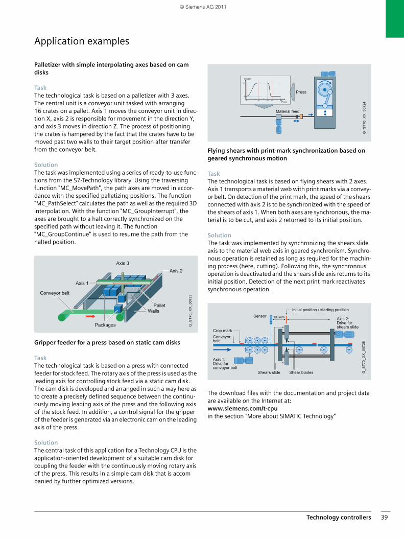
Technology controllers 39
Application examples
Palletizer with simple interpolating axes based on cam disks
TaskThe technological task is based on a palletizer with 3 axes. The central unit is a conveyor unit tasked with arranging 16 crates on a pallet. Axis 1 moves the conveyor unit in direc-tion X, axis 2 is responsible for movement in the direction Y, and axis 3 moves in direction Z. The process of positioning the crates is hampered by the fact that the crates have to be moved past two walls to their target position after transfer from the conveyor belt.
SolutionThe task was implemented using a series of ready-to-use func-tions from the S7-Technology library. Using the traversing function "MC_MovePath", the path axes are moved in accor-dance with the specified palletizing positions. The function "MC_PathSelect" calculates the path as well as the required 3D interpolation. With the function "MC_GroupInterrupt", the axes are brought to a halt correctly synchronized on the specified path without leaving it. The function "MC_GroupContinue" is used to resume the path from the halted position.
Gripper feeder for a press based on static cam disks
TaskThe technological task is based on a press with connected feeder for stock feed. The rotary axis of the press is used as the leading axis for controlling stock feed via a static cam disk. The cam disk is developed and arranged in such a way here as to create a precisely defined sequence between the continu-ously moving leading axis of the press and the following axis of the stock feed. In addition, a control signal for the gripper of the feeder is generated via an electronic cam on the leading axis of the press.
SolutionThe central task of this application for a Technology CPU is the application-oriented development of a suitable cam disk for coupling the feeder with the continuously moving rotary axis of the press. This results in a simple cam disk that is accompanied by further optimized versions.
Flying shears with print-mark synchronization based on geared synchronous motion
TaskThe technological task is based on flying shears with 2 axes. Axis 1 transports a material web with print marks via a convey-or belt. On detection of the print mark, the speed of the shears connected with axis 2 is to be synchronized with the speed of the shears of axis 1. When both axes are synchronous, the ma-terial is to be cut, and axis 2 returned to its initial position.
SolutionThe task was implemented by synchronizing the shears slide axis to the material web axis in geared synchronism. Synchro-nous operation is retained as long as required for the machin-ing process (here, cutting). Following this, the synchronous operation is deactivated and the shears slide axis returns to its initial position. Detection of the next print mark reactivates synchronous operation.
The download files with the documentation and project data are available on the Internet at:www.siemens.com/t-cpuin the section "More about SIMATIC Technology"
Axis 3Axis 2
Axis 1
WallsPallet
Packages
Conveyor belt
G_S
T70_
XX
_007
23
Press
Gripper
Press
Material feed
G_S
T70_
XX
_007
24
0
144
5 270225135 360
Shears slide
Axis 1:Drive for conveyor belt
Axis 2:Drive for shears slide
Crop markConveyorbelt
Shear blades
Initial position / starting positionSensor 100 mm
G_S
T70_
XX
_007
25
SIMATIC_Technology_04_2011_en.book Seite 39 Freitag, 25. März 2011 3:51 15
© Siemens AG 2011
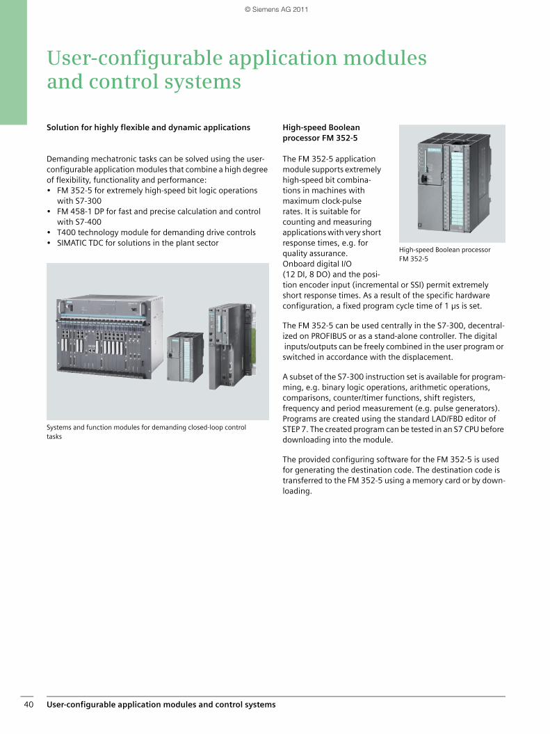
User-configurable application modules and control systems40
User-configurable application modules and control systems
Solution for highly flexible and dynamic applications
Demanding mechatronic tasks can be solved using the user-configurable application modules that combine a high degree of flexibility, functionality and performance: • FM 352-5 for extremely high-speed bit logic operations
with S7-300• FM 458-1 DP for fast and precise calculation and control
with S7-400• T400 technology module for demanding drive controls• SIMATIC TDC for solutions in the plant sector
Systems and function modules for demanding closed-loop control tasks
High-speed Boolean processor FM 352-5
The FM 352-5 application module supports extremely high-speed bit combina-tions in machines with maximum clock-pulse rates. It is suitable for counting and measuring applications with very short response times, e.g. for quality assurance. Onboard digital I/O (12 DI, 8 DO) and the posi-tion encoder input (incremental or SSI) permit extremely short response times. As a result of the specific hardware configuration, a fixed program cycle time of 1 µs is set.
The FM 352-5 can be used centrally in the S7-300, decentral-ized on PROFIBUS or as a stand-alone controller. The digital inputs/outputs can be freely combined in the user program or switched in accordance with the displacement.
A subset of the S7-300 instruction set is available for program-ming, e.g. binary logic operations, arithmetic operations, comparisons, counter/timer functions, shift registers, frequency and period measurement (e.g. pulse generators). Programs are created using the standard LAD/FBD editor of STEP 7. The created program can be tested in an S7 CPU before downloading into the module.
The provided configuring software for the FM 352-5 is used for generating the destination code. The destination code is transferred to the FM 352-5 using a memory card or by down-loading.
High-speed Boolean processor FM 352-5
SIMATIC_Technology_04_2011_en.book Seite 40 Freitag, 25. März 2011 3:51 15
© Siemens AG 2011
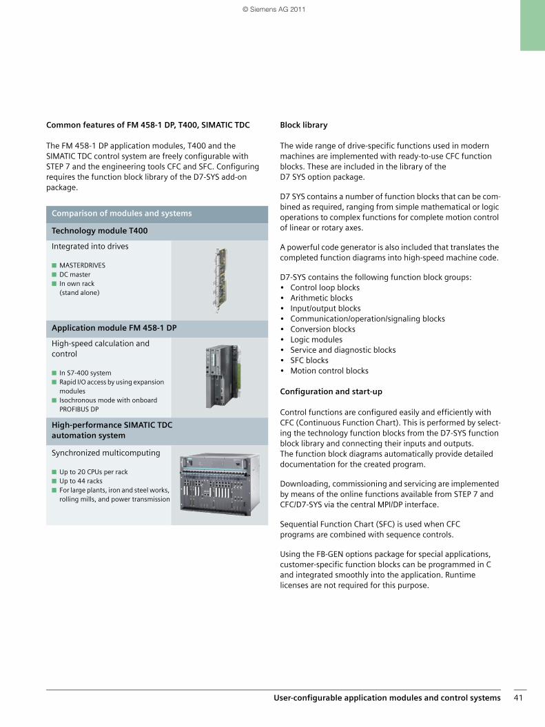
User-configurable application modules and control systems 41
Common features of FM 458-1 DP, T400, SIMATIC TDC
The FM 458-1 DP application modules, T400 and the SIMATIC TDC control system are freely configurable with STEP 7 and the engineering tools CFC and SFC. Configuring requires the function block library of the D7-SYS add-on package.
Block library
The wide range of drive-specific functions used in modern machines are implemented with ready-to-use CFC function blocks. These are included in the library of the D7 SYS option package.
D7 SYS contains a number of function blocks that can be com-bined as required, ranging from simple mathematical or logic operations to complex functions for complete motion control of linear or rotary axes.
A powerful code generator is also included that translates the completed function diagrams into high-speed machine code.
D7-SYS contains the following function block groups:• Control loop blocks• Arithmetic blocks• Input/output blocks• Communication/operation/signaling blocks• Conversion blocks• Logic modules• Service and diagnostic blocks• SFC blocks• Motion control blocks
Configuration and start-up
Control functions are configured easily and efficiently with CFC (Continuous Function Chart). This is performed by select-ing the technology function blocks from the D7-SYS function block library and connecting their inputs and outputs. The function block diagrams automatically provide detailed documentation for the created program.
Downloading, commissioning and servicing are implemented by means of the online functions available from STEP 7 and CFC/D7-SYS via the central MPI/DP interface.
Sequential Function Chart (SFC) is used when CFC programs are combined with sequence controls.
Using the FB-GEN options package for special applications, customer-specific function blocks can be programmed in C and integrated smoothly into the application. Runtime licenses are not required for this purpose.
Comparison of modules and systems
Technology module T400
Integrated into drives
■ MASTERDRIVES■ DC master■ In own rack
(stand alone)
Application module FM 458-1 DP
High-speed calculation and control
■ In S7-400 system■ Rapid I/O access by using expansion
modules■ Isochronous mode with onboard
PROFIBUS DP
High-performance SIMATIC TDC automation system
Synchronized multicomputing
■ Up to 20 CPUs per rack■ Up to 44 racks■ For large plants, iron and steel works,
rolling mills, and power transmission
SIMATIC_Technology_04_2011_en.book Seite 41 Freitag, 25. März 2011 3:51 15
© Siemens AG 2011
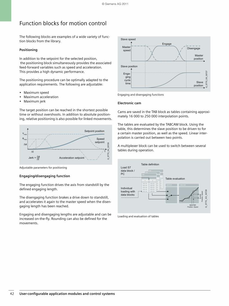
User-configurable application modules and control systems42
Function blocks for motion control
The following blocks are examples of a wide variety of func-tion blocks from the library.
Positioning
In addition to the setpoint for the selected position, the positioning block simultaneously provides the associated feed-forward variables such as speed and acceleration. This provides a high dynamic performance.
The positioning procedure can be optimally adapted to the application requirements. The following are adjustable:
• Maximum speed• Maximum acceleration• Maximum jerk
The target position can be reached in the shortest possible time or without overshoots. In addition to absolute position-ing, relative positioning is also possible for linked movements.
Adjustable parameters for positioning
Engaging/disengaging function
The engaging function drives the axis from standstill by the defined engaging length.
The disengaging function brakes a drive down to standstill, and accelerates it again to the master speed when the disen-gaging length has been reached.
Engaging and disengaging lengths are adjustable and can be increased on-the-fly. Rounding can also be defined for the movements.
Engaging and disengaging functions
Electronic cam
Cams are saved in the TAB block as tables containing approxi-mately 16 000 to 250 000 interpolation points.
The tables are evaluated by the TABCAM block. Using the table, this determines the slave position to be driven to for a certain master position, as well as the speed. Linear inter-polation is carried out between two points.
A multiplexer block can be used to switch between several tables during operation.
Loading and evaluation of tables
Jerk =
Setpoint position
Speed setpoint
Acceleration setpoint G_S
T70_
XX
_007
26∆a
∆t t
amax
vmax
∆a∆t
Disengage
Engage
Slave position
Master position
Slave speed
Slave position
Enga-ging
cycle time
Masterspeed
G_S
T70_
XX
_007
27
Individual loading withdata blocks
Table evaluation
Table definitionLoad S7 data block / PC
SLA
VE
Pos
ition
, Spe
ed
MASTERPosition, Speed G
_ST7
0_X
X_0
0728
SIMATIC_Technology_04_2011_en.book Seite 42 Freitag, 25. März 2011 3:51 15
© Siemens AG 2011

User-configurable application modules and control systems 43
Application module FM 458-1 DP
The FM 458-1 DP application module integrates fast, accurate calculation and control into S7-400.
With the function block library, FM 458-1 DP has all the neces-sary mechatronic functions for solving open-loop control, closed-loop control, motion control and technological tasks.
Equidistant sampling times of 100 μs and more support dy-namic control tasks, e.g. for increasing accuracy or speeding up the machine cycle.
With firmware version V2, the FM 458-1 DP offers even more performance at the same price.
Technological blocks created by users themselves can be protected by a dongle.
Possible application areas in-clude the speed-synchro-nized and position-synchro-nized operation of linear and rotary axes, engaging and disengaging of other axes, winders and hydraulic con-trols.
Communication
Communication with peers takes place over the PROFIBUS DP interface on the FM 458-1 DP. This offers the following characteristics:
• Constant bus cycle time, i.e. the PROFIBUS DP cycle is always precisely the same length.
• Isochronous, i.e. the CPU, I/O and user program are synchronized with the PROFIBUS cycle.
• Slave-to-slave communication, i.e. the configured slaves can exchange data with each other directly without the need for any additional configuring work on the FM 458-1 DP.
• Routing capability, i.e. all nodes are accessed over oneinterface, e.g. MPI or PROFIBUS DP and optionally also Industrial Ethernet.
Approx. 100 drives of the SIMOVERT Masterdrives series or SIMOREG series can be connected per ring over the high-speed, fiber-optic SIMOLINK connection.
Benefits
■ High processing speed, computing performance, positioning accuracy and large number of axes
■ More advanced closed-loop control at higher clock rates (100 µs)
■ Motion control with high dynamic response■ Universally implementable for all technology applica-
tions used in mechanical and plant engineering■ Extensive function block library■ Highest possible flexibility for individual applications■ Freely configurable graphically with the SIMATIC
tools STEP 7 and CFC, optionally SFC as well as C programs
Computing and control with the FM 458
Task Features
Counting / Measuring Suitable for a wide range of different counting and measuring tasks with incremental or absolute value encoders up to a maximum of 2.5 MHz.
Cam control 16 digital outputs as cam tracks (displacement or time cams). Each track can be individually adapted to the task with a derivative action or overrun. Dynamic derivative action, dynamic hysteresis
Closed-loop control Controller structures/types are freely programmable, e.g. fixed value control, follow-on control, cascading control, ratio and mixer controls, continuous and override control, pressure, level and temperature control, hydraulic control, drive control
Motion Control Open/closed-loop controlled positioning of individual axes as well as multi-axis applications over PROFIBUS DP or SIMOLINK
SIMATIC_Technology_04_2011_en.book Seite 43 Freitag, 25. März 2011 3:51 15
© Siemens AG 2011
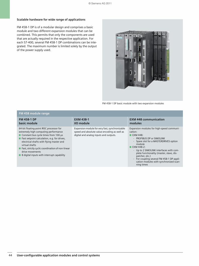
User-configurable application modules and control systems44
Scalable hardware for wide range of applications
FM 458-1 DP is of a modular design and comprises a basic module and two different expansion modules that can be combined. This permits that only the components are used that are actually required in the respective application. For each S7-400, several FM 458-1 DP combinations can be inte-grated. The maximum number is limited solely by the output of the power supply used.
FM 458-1 DP basic module with two expansion modules
FM 458 module range
FM 458-1 DP basic module
EXM 438-1 I/O module
EXM 448 communication modules
64-bit floating-point RISC processor for extremely high computing performance■ Constant bus cycle times from 100 µs■ Fast setpoint calculation, e.g. for drives,
electrical shafts with flying master and virtual shafts
■ Fast, strictly cyclic coordination of non-linear drive movements
■ 8 digital inputs with interrupt capability
Expansion module for very fast, synchronizable speed and absolute value encoding as well as digital and analog inputs and outputs.
Expansion modules for high-speed communi-cation: ■ EXM 448:
- PROFIBUS DP or SIMOLINK- Spare slot for a MASTERDRIVES option
module■ EXM 448-2:
- Up to 2 SIMOLINK interfaces with com-plete functionality (master, slave, dis-patcher, etc.)
- For coupling several FM 458-1 DP appli-cation modules with synchronized scan-ning times
SIMATIC_Technology_04_2011_en.book Seite 44 Freitag, 25. März 2011 3:51 15
© Siemens AG 2011
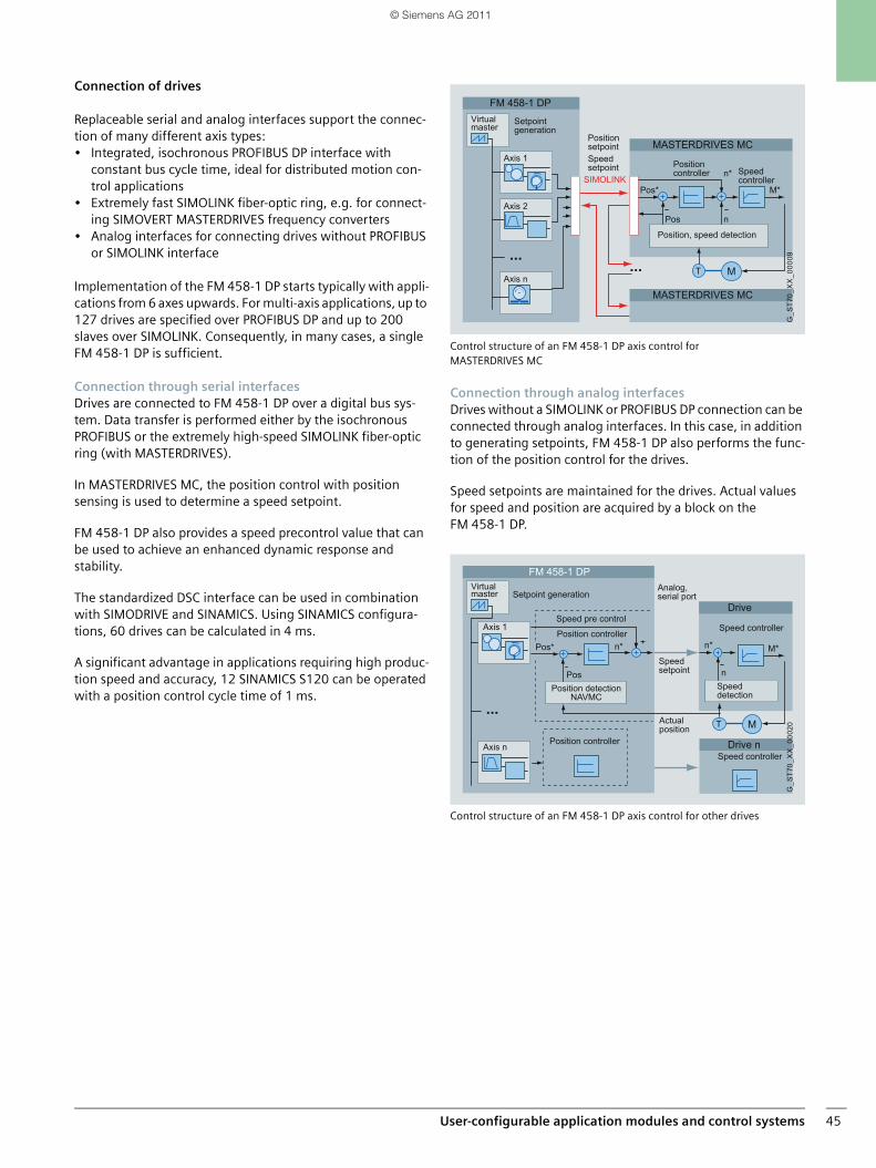
User-configurable application modules and control systems 45
Connection of drives
Replaceable serial and analog interfaces support the connec-tion of many different axis types:• Integrated, isochronous PROFIBUS DP interface with
constant bus cycle time, ideal for distributed motion con-trol applications
• Extremely fast SIMOLINK fiber-optic ring, e.g. for connect-ing SIMOVERT MASTERDRIVES frequency converters
• Analog interfaces for connecting drives without PROFIBUS or SIMOLINK interface
Implementation of the FM 458-1 DP starts typically with appli-cations from 6 axes upwards. For multi-axis applications, up to 127 drives are specified over PROFIBUS DP and up to 200 slaves over SIMOLINK. Consequently, in many cases, a single FM 458-1 DP is sufficient.
Connection through serial interfacesDrives are connected to FM 458-1 DP over a digital bus sys-tem. Data transfer is performed either by the isochronous PROFIBUS or the extremely high-speed SIMOLINK fiber-optic ring (with MASTERDRIVES).
In MASTERDRIVES MC, the position control with position sensing is used to determine a speed setpoint.
FM 458-1 DP also provides a speed precontrol value that can be used to achieve an enhanced dynamic response and stability.
The standardized DSC interface can be used in combination with SIMODRIVE and SINAMICS. Using SINAMICS configura-tions, 60 drives can be calculated in 4 ms.
A significant advantage in applications requiring high produc-tion speed and accuracy, 12 SINAMICS S120 can be operated with a position control cycle time of 1 ms.
Control structure of an FM 458-1 DP axis control for MASTERDRIVES MC
Connection through analog interfacesDrives without a SIMOLINK or PROFIBUS DP connection can be connected through analog interfaces. In this case, in addition to generating setpoints, FM 458-1 DP also performs the func-tion of the position control for the drives.
Speed setpoints are maintained for the drives. Actual values for speed and position are acquired by a block on the FM 458-1 DP.
Control structure of an FM 458-1 DP axis control for other drives
MT
Position, speed detection
n
n*
Setpoint generation
Position setpoint
Positioncontroller
Speed setpoint Speed
controller
Virtual master
Axis 1
Axis 2
Axis n
Pos*
Pos
M*
FM 458-1 DP
MASTERDRIVES MC
MASTERDRIVES MC
SIMOLINK
G_S
T70_
XX
_000
09
MT
Setpoint generationVirtual master
Axis 1
Axis n
Position detectionNAVMC
n* n*
n
Analog,serial port
Position controller
Position controller
Speed pre control
Actual position
Speed controller
Speed controller
Speed setpoint
Speed detection
Pos*
Pos
M*
Drive n
Drive
FM 458-1 DP
G_S
T70_
XX
_000
20
SIMATIC_Technology_04_2011_en.book Seite 45 Freitag, 25. März 2011 3:51 15
© Siemens AG 2011
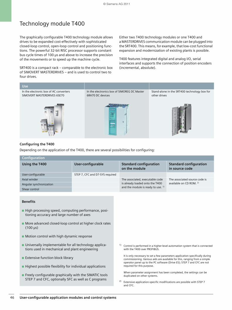
User-configurable application modules and control systems46
Technology module T400
The graphically configurable T400 technology module allows drives to be expanded cost-effectively with sophisticated closed-loop control, open-loop control and positioning func-tions. The powerful 32-bit RISC processor supports constant bus cycle times of 100 µs and above to increase the precision of the movements or to speed up the machine cycle.
SRT400 is a compact rack – comparable to the electronic box of SIMOVERT MASTERDRIVES – and is used to control two to four drives.
Either two T400 technology modules or one T400 and a MASTERDRIVES communication module can be plugged into the SRT400. This means, for example, that low-cost functional expansion and modernization of existing plants is possible.
T400 features integrated digital and analog I/O, serial interfaces and supports the connection of position encoders (incremental, absolute).
Configuring the T400
Depending on the application of the T400, there are several possibilities for configuring:
1) Control is performed in a higher-level automation system that is connected with the T400 over PROFIBUS.
It is only necessary to set a few parameters application-specifically during commissioning. Various aids are available for this, ranging from a simple operator panel up to the PC software (Drive ES); STEP 7 and CFC are not required for this purpose.
When parameter assignment has been completed, the settings can be duplicated on other systems.
2) Extensive application-specific modifications are possible with STEP 7 and CFC.
Use
In the electronic box of AC converters SIMOVERT MASTERDRIVES 6SE70
In the electronics box of SIMOREG DC Master 6RA70 DC devices
Stand-alone in the SRT400 technology box for other drives
Configuration
Using the T400 User-configurable Standard configuration on the module
Standard configurationin source code
User-configurable STEP 7, CFC and D7-SYS required
Axial winder The associated, executable code is already loaded onto the T400 and the module is ready to use. 1)
The associated source code is available on CD ROM. 2)
Angular synchronization
Shear control
Benefits
■ High processing speed, computing performance, posi-tioning accuracy and large number of axes
■ More advanced closed-loop control at higher clock rates (100 µs)
■ Motion control with high dynamic response
■ Universally implementable for all technology applica-tions used in mechanical and plant engineering
■ Extensive function block library
■ Highest possible flexibility for individual applications
■ Freely configurable graphically with the SIMATIC tools STEP 7 and CFC, optionally SFC as well as C programs
SIMATIC_Technology_04_2011_en.book Seite 46 Freitag, 25. März 2011 3:51 15
© Siemens AG 2011
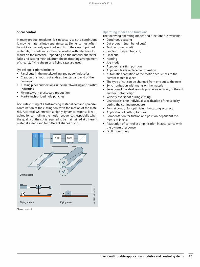
User-configurable application modules and control systems 47
Shear control
In many production plants, it is necessary to cut a continuous-ly moving material into separate parts. Elements must often be cut to a precisely specified length. In the case of printed materials, the cuts must often be located with reference to marks on the material. Depending on the material character-istics and cutting method, drum shears (rotating arrangement of shears), flying shears and flying saws are used.
Typical applications include:• Panel cuts in the metalworking and paper industries• Creation of smooth cut ends at the start and end of the
conveyor• Cutting pipes and sections in the metalworking and plastics
industries• Flying saws in pressboard production• Mark-synchronized hole punches
Accurate cutting of a fast-moving material demands precise coordination of the cutting tool with the motion of the mate-rial. A control system with a highly dynamic response is re-quired for controlling the motion sequences, especially when the quality of the cut is required to be maintained at different material speeds and for different shapes of cut.
Shear control
Operating modes and functionsThe following operating modes and functions are available:• Continuous cutting• Cut program (number of cuts)• Test cut (one panel)• Single cut (separating cut)• Final cut• Homing• Jog mode• Approach starting position• Approach blade replacement position• Automatic adaptation of the motion sequences to the
current material speed• The type of cut can be changed from one cut to the next• Synchronization with marks on the material• Selection of the ideal velocity profile for accuracy of the cut
and for motor design• Velocity overshoot during cutting• Characteristic for individual specification of the velocity
during the cutting procedure• Format control for optimizing the cutting accuracy• Application of cutting torques• Compensation for friction and position-dependent mo-
ments of inertia• Adaptation of controller amplification in accordance with
the dynamic response• Fault monitoring
Flying shears
Drum shears
Flying saws G_S
T70_
XX
_007
29
T400CBP
SIMATIC_Technology_04_2011_en.book Seite 47 Freitag, 25. März 2011 3:51 15
© Siemens AG 2011
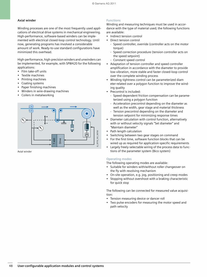
User-configurable application modules and control systems48
Axial winder
Winding processes are one of the most frequently used appli-cations of electrical drive systems in mechanical engineering. High-performance, software-based winders can be imple-mented with electrical closed-loop control technology. Until now, generating programs has involved a considerable amount of work. Ready-to-use standard configurations have minimized this overhead.
High-performance, high-precision winders and unwinders can be implemented, for example, with SPW420 for the following applications:• Film take-off units• Textile machines• Printing machines• Coating systems• Paper finishing machines• Winders in wire-drawing machines• Coilers in metalworking
Axial winder
FunctionsWinding and measuring techniques must be used in accor-dance with the type of material used; the following functions are available:• Indirect tension control• Direct tension control
- Speed controller, override (controller acts on the motor torque)
- Speed correction procedure (tension controller acts on the speed setpoint)
- Constant speed control• Adaptation of tension controller and speed controller
amplification in accordance with the diameter to provide low-vibration, more stable and faster closed-loop control over the complete winding process
• Winding tightness control can be parameterized diameter-related over a polygon function to improve the wind-ing quality
• Precontrol is included:- Speed-dependent friction compensation can be parame-
terized using a polygon function- Acceleration precontrol depending on the diameter as
well as the width, gear stage and material thickness- Tension precontrol depending on the diameter and
tension setpoint for minimizing response times• Diameter calculation with control function, alternatively
with or without velocity signals "Set diameter" and "Maintain diameter"
• Path length calculation• Switching between two gear stages on command• For the first time, software function blocks that can be
wired up as required for application-specific requirements• Largely freely-selectable wiring of the process data to func-
tions of the parameter system (Bico system)
Operating modesThe following operating modes are available:• Suitable for winders with/without roller changeover on
the fly with revolving mechanism• On-site operation, e.g. jog, positioning and creep modes• Stopping without overshoot with a braking characteristic
for quick stop
The following can be connected for measured value acquisi-tion:• Tension measuring device or dancer roll• Two pulse encoders for measuring the motor speed and
path velocity
Driv
e
T 40
0
G_S
T70_
XX
_007
30
SIMATIC_Technology_04_2011_en.book Seite 48 Freitag, 25. März 2011 3:51 15
© Siemens AG 2011
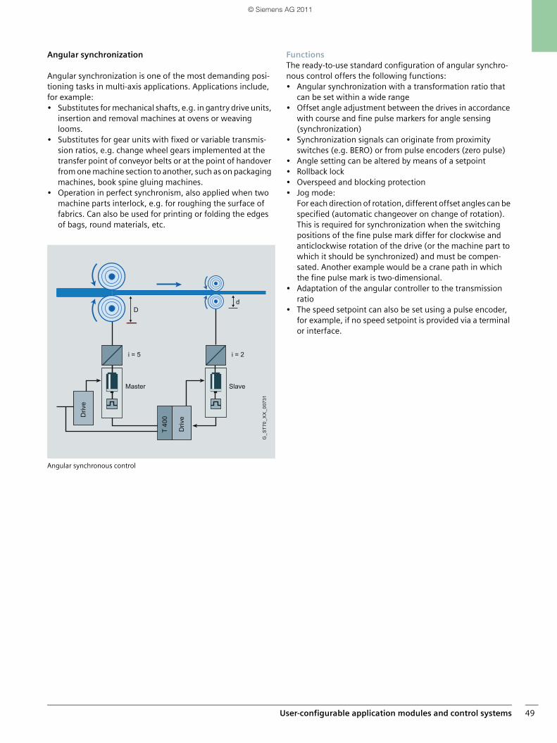
User-configurable application modules and control systems 49
Angular synchronization
Angular synchronization is one of the most demanding posi-tioning tasks in multi-axis applications. Applications include, for example:• Substitutes for mechanical shafts, e.g. in gantry drive units,
insertion and removal machines at ovens or weaving looms.
• Substitutes for gear units with fixed or variable transmis-sion ratios, e.g. change wheel gears implemented at the transfer point of conveyor belts or at the point of handover from one machine section to another, such as on packaging machines, book spine gluing machines.
• Operation in perfect synchronism, also applied when two machine parts interlock, e.g. for roughing the surface of fabrics. Can also be used for printing or folding the edges of bags, round materials, etc.
Angular synchronous control
FunctionsThe ready-to-use standard configuration of angular synchro-nous control offers the following functions:• Angular synchronization with a transformation ratio that
can be set within a wide range• Offset angle adjustment between the drives in accordance
with course and fine pulse markers for angle sensing (synchronization)
• Synchronization signals can originate from proximity switches (e.g. BERO) or from pulse encoders (zero pulse)
• Angle setting can be altered by means of a setpoint• Rollback lock• Overspeed and blocking protection• Jog mode:
For each direction of rotation, different offset angles can be specified (automatic changeover on change of rotation). This is required for synchronization when the switching positions of the fine pulse mark differ for clockwise and anticlockwise rotation of the drive (or the machine part to which it should be synchronized) and must be compen-sated. Another example would be a crane path in which the fine pulse mark is two-dimensional.
• Adaptation of the angular controller to the transmission ratio
• The speed setpoint can also be set using a pulse encoder, for example, if no speed setpoint is provided via a terminal or interface.
Master Slave
Driv
eDriv
e
Dd
i = 5 i = 2
T 40
0
G_S
T70_
XX
_007
31
SIMATIC_Technology_04_2011_en.book Seite 49 Freitag, 25. März 2011 3:51 15
© Siemens AG 2011
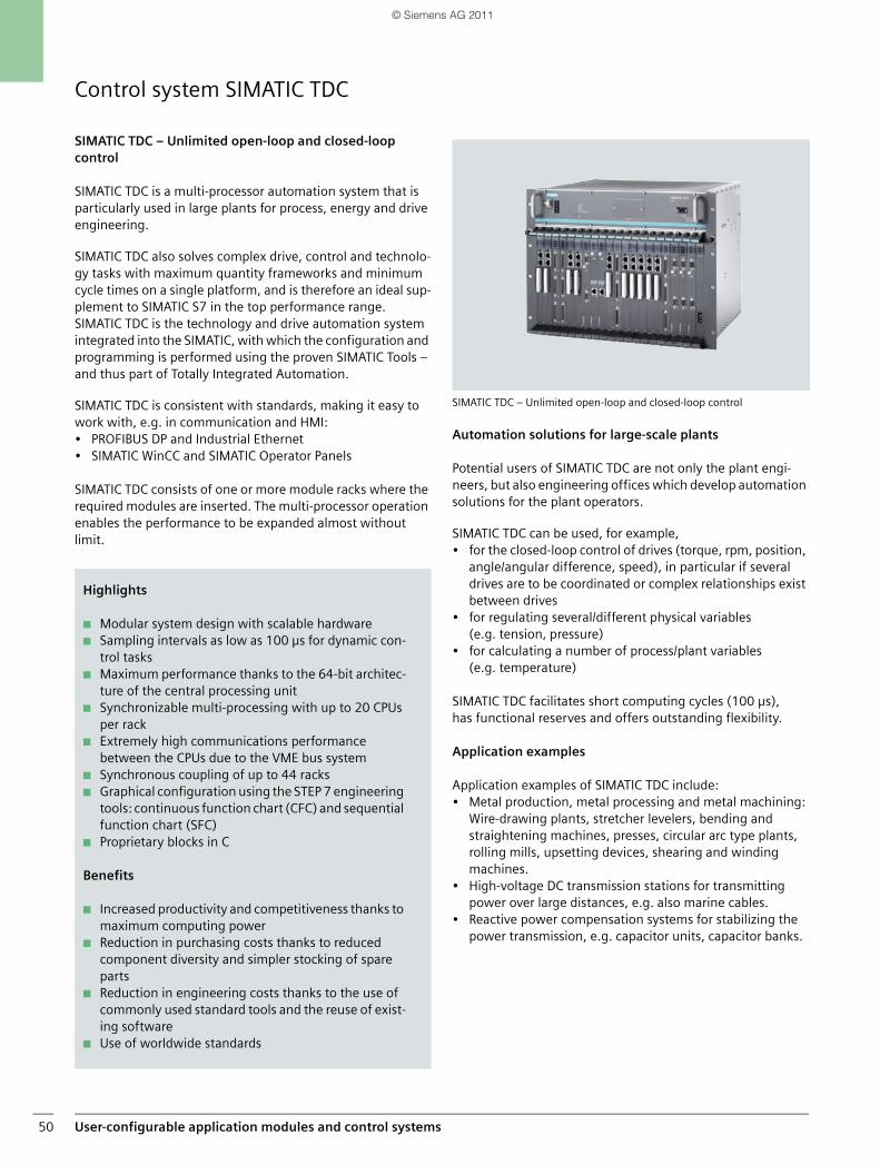
User-configurable application modules and control systems50
Control system SIMATIC TDC
SIMATIC TDC – Unlimited open-loop and closed-loop control
SIMATIC TDC is a multi-processor automation system that is particularly used in large plants for process, energy and drive engineering.
SIMATIC TDC also solves complex drive, control and technolo-gy tasks with maximum quantity frameworks and minimum cycle times on a single platform, and is therefore an ideal sup-plement to SIMATIC S7 in the top performance range. SIMATIC TDC is the technology and drive automation system integrated into the SIMATIC, with which the configuration and programming is performed using the proven SIMATIC Tools – and thus part of Totally Integrated Automation.
SIMATIC TDC is consistent with standards, making it easy to work with, e.g. in communication and HMI:• PROFIBUS DP and Industrial Ethernet• SIMATIC WinCC and SIMATIC Operator Panels
SIMATIC TDC consists of one or more module racks where the required modules are inserted. The multi-processor operation enables the performance to be expanded almost without limit.
SIMATIC TDC – Unlimited open-loop and closed-loop control
Automation solutions for large-scale plants
Potential users of SIMATIC TDC are not only the plant engi-neers, but also engineering offices which develop automation solutions for the plant operators.
SIMATIC TDC can be used, for example,• for the closed-loop control of drives (torque, rpm, position,
angle/angular difference, speed), in particular if several drives are to be coordinated or complex relationships exist between drives
• for regulating several/different physical variables (e.g. tension, pressure)
• for calculating a number of process/plant variables (e.g. temperature)
SIMATIC TDC facilitates short computing cycles (100 µs), has functional reserves and offers outstanding flexibility.
Application examples
Application examples of SIMATIC TDC include:• Metal production, metal processing and metal machining:
Wire-drawing plants, stretcher levelers, bending and straightening machines, presses, circular arc type plants, rolling mills, upsetting devices, shearing and winding machines.
• High-voltage DC transmission stations for transmitting power over large distances, e.g. also marine cables.
• Reactive power compensation systems for stabilizing the power transmission, e.g. capacitor units, capacitor banks.
Highlights
■ Modular system design with scalable hardware■ Sampling intervals as low as 100 µs for dynamic con-
trol tasks■ Maximum performance thanks to the 64-bit architec-
ture of the central processing unit■ Synchronizable multi-processing with up to 20 CPUs
per rack■ Extremely high communications performance
between the CPUs due to the VME bus system■ Synchronous coupling of up to 44 racks■ Graphical configuration using the STEP 7 engineering
tools: continuous function chart (CFC) and sequential function chart (SFC)
■ Proprietary blocks in C
Benefits
■ Increased productivity and competitiveness thanks to maximum computing power
■ Reduction in purchasing costs thanks to reduced component diversity and simpler stocking of spare parts
■ Reduction in engineering costs thanks to the use of commonly used standard tools and the reuse of exist-ing software
■ Use of worldwide standards
SIMATIC_Technology_04_2011_en.book Seite 50 Freitag, 25. März 2011 3:51 15
© Siemens AG 2011
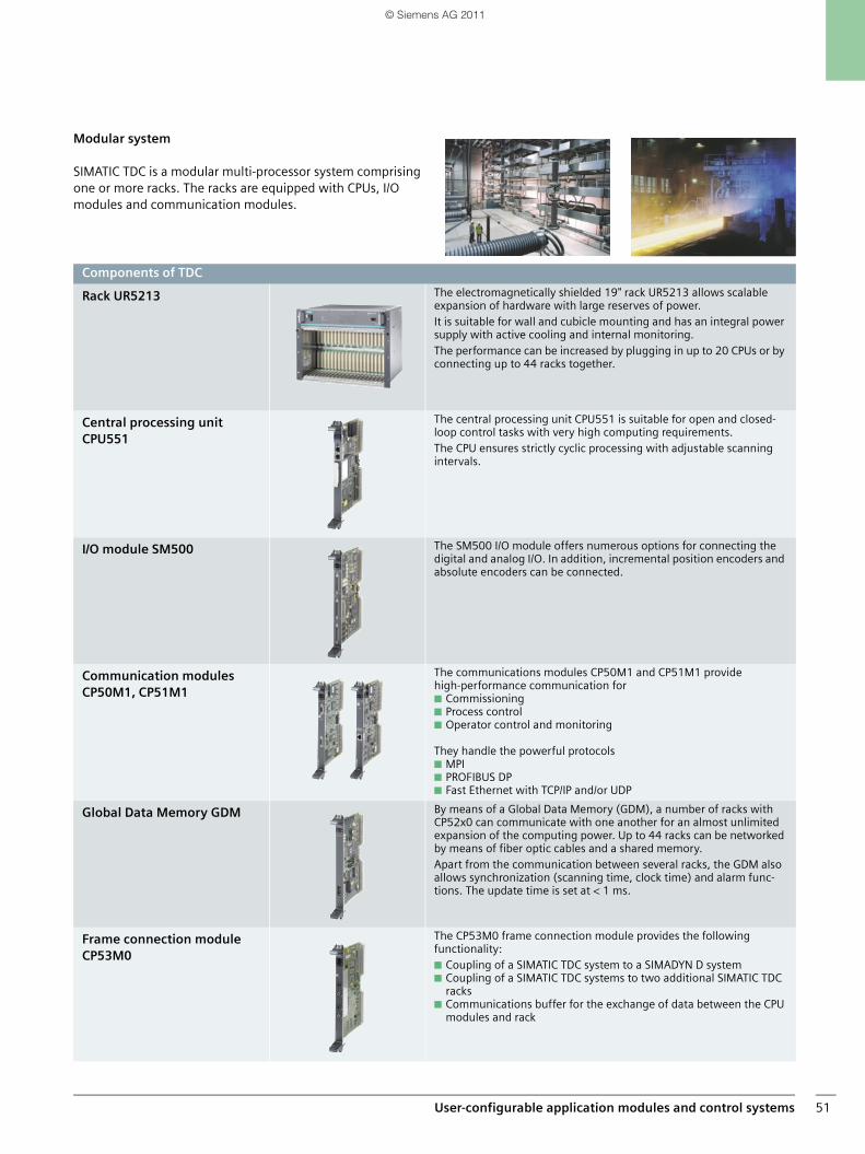
User-configurable application modules and control systems 51
Modular system
SIMATIC TDC is a modular multi-processor system comprising one or more racks. The racks are equipped with CPUs, I/O modules and communication modules.
Components of TDC
Rack UR5213 The electromagnetically shielded 19" rack UR5213 allows scalable expansion of hardware with large reserves of power. It is suitable for wall and cubicle mounting and has an integral power supply with active cooling and internal monitoring.The performance can be increased by plugging in up to 20 CPUs or by connecting up to 44 racks together.
Central processing unit CPU551
The central processing unit CPU551 is suitable for open and closed-loop control tasks with very high computing requirements.The CPU ensures strictly cyclic processing with adjustable scanningintervals.
I/O module SM500 The SM500 I/O module offers numerous options for connecting the digital and analog I/O. In addition, incremental position encoders and absolute encoders can be connected.
Communication modules CP50M1, CP51M1
The communications modules CP50M1 and CP51M1 provide high-performance communication for■ Commissioning■ Process control■ Operator control and monitoring
They handle the powerful protocols■ MPI■ PROFIBUS DP■ Fast Ethernet with TCP/IP and/or UDP
Global Data Memory GDM By means of a Global Data Memory (GDM), a number of racks with CP52x0 can communicate with one another for an almost unlimited expansion of the computing power. Up to 44 racks can be networked by means of fiber optic cables and a shared memory.Apart from the communication between several racks, the GDM also allows synchronization (scanning time, clock time) and alarm func-tions. The update time is set at < 1 ms.
Frame connection module CP53M0
The CP53M0 frame connection module provides the followingfunctionality: ■ Coupling of a SIMATIC TDC system to a SIMADYN D system■ Coupling of a SIMATIC TDC systems to two additional SIMATIC TDC
racks■ Communications buffer for the exchange of data between the CPU
modules and rack
SIMATIC_Technology_04_2011_en.book Seite 51 Freitag, 25. März 2011 3:51 15
© Siemens AG 2011
SIMATIC Technology52
SIMATIC TechnologyNotes
SIMATIC_Technology_04_2011_en.book Seite 52 Freitag, 25. März 2011 3:51 15
© Siemens AG 2011
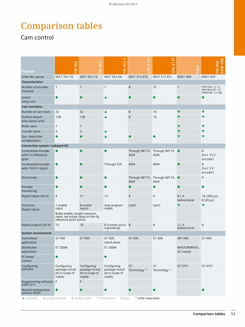
Comparison tables 53
Comparison tablesCam control
Feature FM 3
52
FM 4
52
FM 3
52
-5
CPU
31
5T
CPU
31
7T
T40
0
FM 4
58
EXM
43
8
Order No. group 6ES7 352-1A. 6ES7 452-1A. 6ES7 352-5A. 6ES7 315-6TG. 6ES7 317-6TJ. 6DD1 606- 6DD1 607-
Characteristics
Number of encoder channels
1 1 1 8 32 1 EXM 438: 2 x 12; PROFIBUS DP: 127SIMOLINK: 2 x 200
Linear/rotary axis
● ● ▲ ● ● ● ●
Cam functions
Number of cam track 32 32 ▲ 8 16 ▼ ▼
Position-based / time-based cams
128 128 ▲ 8 16 ▼ ▼
Brake cams 1 1 ▼ ▼
Counter cams 3 3 ▲ ▼ ▼
Dyn. dead time compensation
● ● ▲ ● ● ▼ ▼
Connection system / onboard I/O
Incremental encoderwith 5 V difference ignal
● ● ● Through IM174, ADI4
Through IM174, ADI4
● 8 (incl. 15 V encoder)
Incremental encoderwith 15/24 V signal
● ● Through 3 DI ADI4 ADI4 ● 8 (incl. 5 V encoder)
SSI encoder ● ● ● Through IM174, ADI4
Through IM174, ADI4
● 4
Encoder monitoring
● ● ● ● ● ● ●
Digital inputs (24 V) 4 11 12 4 4 8 + 4 bidirectional
16 (200 µs); 8 (20 µs)
Functions Digital inputs
1 enable input
8 enable inputs
User-program-mable
Latch Latch ▼ ▼
Brake enable, length measure-ment, set actual value on the fly, reference point switch
Digital outputs (24 V) 13 16 8 (current sourc-ing/sinking)
8 8 2 + 4 bidirectional
8
System environment
Centralized application
S7-300 S7-400 S7-300,stand-alone
S7-300 S7-300 SRT 400 S7-400
Distributed application
ET 200M ET 200M MASTERDRIVES, DC master
PC-based Control
● ●
Configuring software
Configuring package includ-ed in scope of supply
Configuring package includ-ed in scope of supply
Configuring package includ-ed in scope of supply
S7-Technology 1)
S7-Technology 1)
D7-SYS1) D7-SYS1)
Programming softwareSTEP7 V11
P P
Module replacement without PG/PC
● ● ● ● ● ●
● available ▲ programmable ▼ configurable P Professional B Basic 1) order separately
SIMATIC_Technology_04_2011_en.book Seite 53 Freitag, 25. März 2011 3:51 15
© Siemens AG 2011
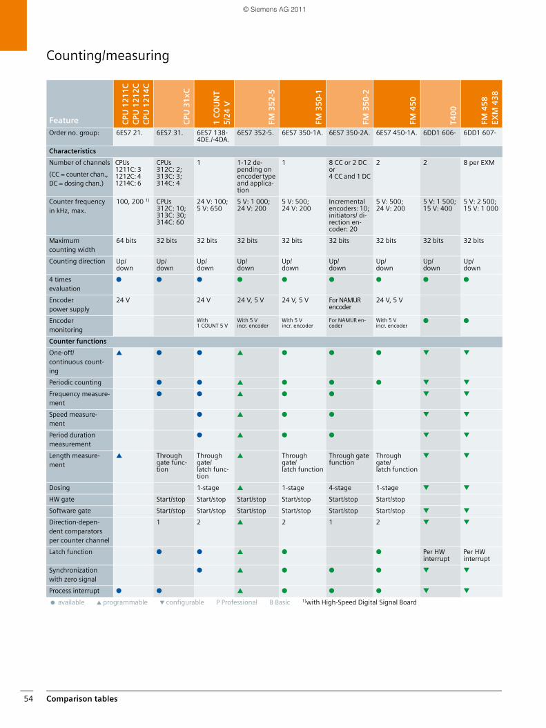
Comparison tables54
Counting/measuring
Feature CPU
12
11
CC
PU 1
21
2C
CPU
12
14
C
CPU
31
xC
1 C
OU
NT
5/2
4 V
FM 3
52
-5
FM 3
50
-1
FM 3
50
-2
FM 4
50
T40
0
FM 4
58
EXM
43
8
Order no. group: 6ES7 21. 6ES7 31. 6ES7 138-4DE./-4DA.
6ES7 352-5. 6ES7 350-1A. 6ES7 350-2A. 6ES7 450-1A. 6DD1 606- 6DD1 607-
Characteristics
Number of channels
(CC = counter chan., DC = dosing chan.)
CPUs1211C: 31212C: 41214C: 6
CPUs 312C: 2; 313C: 3; 314C: 4
1 1-12 de-pending on encoder type and applica-tion
1 8 CC or 2 DC or 4 CC and 1 DC
2 2 8 per EXM
Counter frequency in kHz, max.
100, 200 1) CPUs 312C: 10; 313C: 30; 314C: 60
24 V: 100; 5 V: 650
5 V: 1 000; 24 V: 200
5 V: 500; 24 V: 200
Incremental encoders: 10; initiators/ di-rection en-coder: 20
5 V: 500; 24 V: 200
5 V: 1 500; 15 V: 400
5 V: 2 500; 15 V: 1 000
Maximum counting width
64 bits 32 bits 32 bits 32 bits 32 bits 32 bits 32 bits 32 bits 32 bits
Counting direction Up/down
Up/down
Up/down
Up/down
Up/down
Up/down
Up/down
Up/down
Up/down
4 times evaluation
● ● ● ● ● ● ● ● ●
Encoder power supply
24 V 24 V 24 V, 5 V 24 V, 5 V For NAMUR encoder
24 V, 5 V
Encoder monitoring
With 1 COUNT 5 V
With 5 V incr. encoder
With 5 V incr. encoder
For NAMUR en-coder
With 5 V incr. encoder
● ●
Counter functions
One-off/continuous count-ing
▲ ● ● ▲ ● ● ● ▼ ▼
Periodic counting ● ● ▲ ● ● ● ▼ ▼
Frequency measure-ment
● ● ▲ ● ● ▼ ▼
Speed measure-ment
● ▲ ● ● ▼ ▼
Period duration measurement
● ▲ ● ● ▼ ▼
Length measure-ment
▲ Through gate func-tion
Through gate/latch func-tion
▲ Through gate/latch function
Through gate function
Through gate/latch function
▼ ▼
Dosing 1-stage ▲ 1-stage 4-stage 1-stage ▼ ▼
HW gate Start/stop Start/stop Start/stop Start/stop Start/stop Start/stop
Software gate Start/stop Start/stop Start/stop Start/stop Start/stop Start/stop ▼ ▼
Direction-depen-dent comparators per counter channel
1 2 ▲ 2 1 2 ▼ ▼
Latch function ● ● ▲ ● ● Per HW interrupt
Per HW interrupt
Synchronization with zero signal
● ▲ ● ● ● ▼ ▼
Process interrupt ● ● ▲ ● ● ● ▼ ▼
● available ▲ programmable ▼ configurable P Professional B Basic 1)with High-Speed Digital Signal Board
SIMATIC_Technology_04_2011_en.book Seite 54 Freitag, 25. März 2011 3:51 15
© Siemens AG 2011
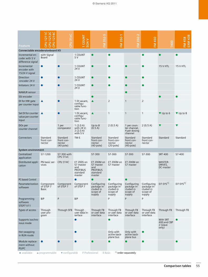
Comparison tables 55
Feature CPU
12
11
CC
PU 1
21
2C
CPU
12
14
C
CPU
31
xC
1 C
OU
NT
5/2
4 V
FM 3
52
-5
FM 3
50
-1
FM 3
50
-2
FM 4
50
T40
0
FM 4
58
EXM
43
8
Connectable encoders/onboard I/O
Incremental en-coder with 5 V difference signal
with Signal Board
1 COUNT 5 V
● ● ● ● ●
Incremental encoder with 15/24 V signal
● ● 1 COUNT 24 V
● ● ● ● 15 V HTL 15 V HTL
Direction encoder 24 V
● ● 1 COUNT 24 V
● ● ● ●
Initiators 24 V ● ● 1 COUNT 24 V
● ● ● ●
NAMUR sensor ●
SSI encoder ● ● ●
DI for HW gate per counter input
▲ ● 1 DI vacant, configu-rable func-tion
▲ 2 1 2
Set DI for counter value per counter input
▲ ● 1 DI vacant, configu-rable func-tion
▲ 1 1 1 ▼ Up to 6 ▼ Up to 8
DOs per counter channel
1 per comparator
1 (2.0 A) with 24 V; 2 (2.0 A) with 5 V
Up to 8 (0.5 A)
2 (0.5 A) 1 per coun-ter channel, 4 per dosing channel
2 (0.5 A) ▼ ▼
Connectors Standard front con-nector
Standard front con-nector (40-pole)
TM-E Standard front con-nector (40-pole)
Standard front con-nector (20-pole)
Standard front con-nector (40-pole)
Standard front con-nector
Standard Standard
System environment
Centralized application
S7-1200 S7-300 with CPU 31xC
S7-300 S7-300 S7-300 S7-300 SRT 400 S7-400
Distributed appli-cation
PN basic ser-vices
CPU 314C ET 200S on S7 master and PROFIBUS standard master
ET 200M on S7 master and PROFIBUS standard master
ET 200M on S7 master
ET 200M on S7 master
MASTER-DRIVES, DC master
PC-based Control ● ● ● ●
Parameterization software
Component of STEP 7 Basic
Component of STEP 7
Component of STEP 7
Configuring package in-cluded in scope of supply
Configuring package in-cluded in scope of supply
Configuring package in-cluded in scope of supply
Configuring package in-cluded in scope of supply
D7-SYS1) D7-SYS1)
Programming software STEP7 V11
B/P P B/P P P P
Types of access Through user pro-gram
Through SFB Through user data in-terface
Through FB or user data interface
Through FB or user data interface
Through FB or user data interface
Through FB or user data interface
Through FB Through FB
Supports isochro-nous mode
● ● With SRT 400 and CBP 2 (slave only)
●
Hot swapping in RUN mode
● Only with active back-plane bus
Only with active back-plane bus
●
Module replace-ment without PG/PC
● ● ● ● ● ● ● ●
● available ▲ programmable ▼ configurable P Professional B Basic 1) order separately
SIMATIC_Technology_04_2011_en.book Seite 55 Freitag, 25. März 2011 3:51 15
© Siemens AG 2011
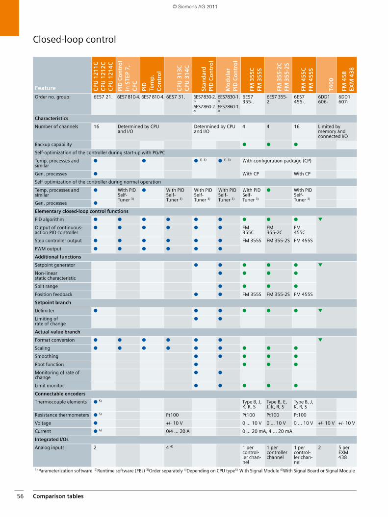
Comparison tables56
Closed-loop control
Feature CPU
12
11
CC
PU 1
21
2C
CPU
12
14
C
PID
Co
ntr
ol
in S
TEP
7,
CFC
PID
Te
mp
.C
on
tro
l
CPU
31
3C
CPU
31
4C
Stan
dar
d
PID
Co
ntr
ol
Mo
du
lar
PID
Co
ntr
ol
FM 3
55
CFM
35
5S
FM 3
55
-2C
FM
35
5-2
S
FM 4
55
CFM
45
5S
T40
0
FM 4
58
EXM
43
8
Order no. group: 6ES7 21. 6ES7 810-4. 6ES7 810-4. 6ES7 31. 6ES7 830-2. 1)
6ES7 860-2. 2)
6ES7830-1. 1) 6ES7860-1. 2)
6ES7 355-.
6ES7 355-2.
6ES7 455-.
6DD1 606-
6DD1 607-
Characteristics
Number of channels 16 Determined by CPU and I/O
Determined by CPU and I/O
4 4 16 Limited bymemory and connected I/O
Backup capability ● ● ●
Self-optimization of the controller during start-up with PG/PC
Temp. processes and similar
● ● ● 1) 3) ● 1) 3) With configuration package (CP)
Gen. processes ● With CP With CP
Self-optimization of the controller during normal operation
Temp. processes and similar
● With PID Self-Tuner 3)
● With PID Self-Tuner 3)
With PID Self-Tuner 3)
With PID Self-Tuner 3)
With PID Self-Tuner 3)
● With PID Self-Tuner 3)
Gen. processes ●
Elementary closed-loop control functions
PID algorithm ● ● ● ● ● ● ● ● ● ▼
Output of continuous-action PID controller
● ● ● ● ● ● FM355C
FM355-2C
FM 455C
Step controller output ● ● ● ● ● ● FM 355S FM 355-2S FM 455S
PWM output ● ● ● ● ● ●
Additional functions
Setpoint generator ● ● ● ● ● ▼
Non-linear static characteristic
● ● ● ●
Split range ● ● ● ●
Position feedback ● ● FM 355S FM 355-2S FM 455S
Setpoint branch
Delimiter ● ● ● ● ● ● ▼
Limiting of rate of change
● ●
Actual-value branch
Format conversion ● ● ● ● ● ● ▼
Scaling ● ● ● ● ● ● ● ● ●
Smoothing ● ● ● ● ●
Root function ● ● ● ●
Monitoring of rate of change
● ●
Limit monitor ● ● ● ● ●
Connectable encoders
Thermocouple elements ● 5) Type B, J, K, R, S
Type B, E, J, K, R, S
Type B, J, K, R, S
Resistance thermometers ● 5) Pt100 Pt100 Pt100 Pt100
Voltage ● +/- 10 V 0 ... 10 V 0 ... 10 V 0 ... 10 V +/- 10 V +/- 10 V
Current ● 6) 0/4 ... 20 A 0 ... 20 mA, 4 ... 20 mA
Integrated I/Os
Analog inputs 2 4 4) 1 per control-ler chan-nel
1 per controller channel
1 per control-ler chan-nel
2 5 per EXM 438
1) Parameterization software 2)Runtime software (FBs) 3)Order separately 4)Depending on CPU type5) With Signal Module 6)With Signal Board or Signal Module
SIMATIC_Technology_04_2011_en.book Seite 56 Freitag, 25. März 2011 3:51 15
© Siemens AG 2011
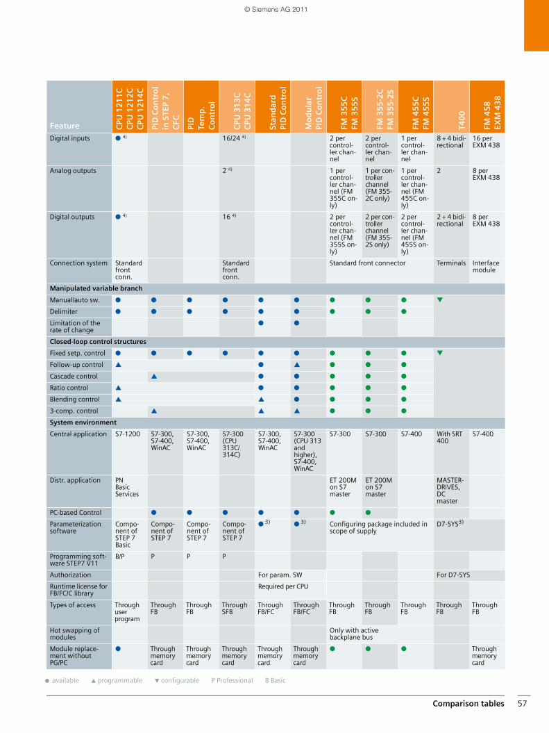
Comparison tables 57
Feature CPU
12
11
CC
PU 1
21
2C
CPU
12
14
C
PID
Co
ntr
ol
in S
TEP
7,
CFC
PID
Te
mp
.C
on
tro
l
CPU
31
3C
CPU
31
4C
Stan
dar
d
PID
Co
ntr
ol
Mo
du
lar
PID
Co
ntr
ol
FM 3
55
CFM
35
5S
FM 3
55
-2C
FM
35
5-2
S
FM 4
55
CFM
45
5S
T40
0
FM 4
58
EXM
43
8
Digital inputs ● 4) 16/24 4) 2 per control-ler chan-nel
2 per control-ler chan-nel
1 per control-ler chan-nel
8 + 4 bidi-rectional
16 per EXM 438
Analog outputs 2 4) 1 per control-ler chan-nel (FM 355C on-ly)
1 per con-troller channel (FM 355-2C only)
1 per control-ler chan-nel (FM 455C on-ly)
2 8 per EXM 438
Digital outputs ● 4) 16 4) 2 per control-ler chan-nel (FM 355S on-ly)
2 per con-troller channel (FM 355-2S only)
2 per control-ler chan-nel (FM 455S on-ly)
2 + 4 bidi-rectional
8 per EXM 438
Connection system Standard front conn.
Standard front conn.
Standard front connector Terminals Interface module
Manipulated variable branch
Manual/auto sw. ● ● ● ● ● ● ● ● ● ▼
Delimiter ● ● ● ● ● ● ● ● ●
Limitation of the rate of change
● ●
Closed-loop control structures
Fixed setp. control ● ● ● ● ● ● ● ● ● ▼
Follow-up control ▲ ● ▲ ● ● ●
Cascade control ▲ ● ● ● ● ●
Ratio control ▲ ● ● ● ● ●
Blending control ▲ ▲ ● ● ● ●
3-comp. control ▲ ▲ ▲ ● ● ●
System environment
Central application S7-1200 S7-300, S7-400,WinAC
S7-300, S7-400,WinAC
S7-300 (CPU 313C/314C)
S7-300, S7-400,WinAC
S7-300 (CPU 313 and higher), S7-400, WinAC
S7-300 S7-300 S7-400 With SRT 400
S7-400
Distr. application PN Basic Services
ET 200M on S7 master
ET 200M on S7 master
MASTER-DRIVES, DC master
PC-based Control ● ● ● ● ● ● ●
Parameterization software
Compo-nent ofSTEP 7 Basic
Compo-nent of STEP 7
Compo-nent of STEP 7
Compo-nent of STEP 7
● 3) ● 3) Configuring package included in scope of supply
D7-SYS3)
Programming soft-ware STEP7 V11
B/P P P P
Authorization For param. SW For D7-SYS
Runtime license for FB/FC/C library
Required per CPU
Types of access Through user program
Through FB
Through FB
Through SFB
Through FB/FC
Through FB/FC
Through FB
Through FB
Through FB
Through FB
Through FB
Hot swapping of modules
Only with active backplane bus
Module replace-ment without PG/PC
● Through memory card
Through memory card
Through memory card
Through memory card
Through memory card
● ● ● Through memory card
● available ▲ programmable ▼ configurable P Professional B Basic
SIMATIC_Technology_04_2011_en.book Seite 57 Freitag, 25. März 2011 3:51 15
© Siemens AG 2011
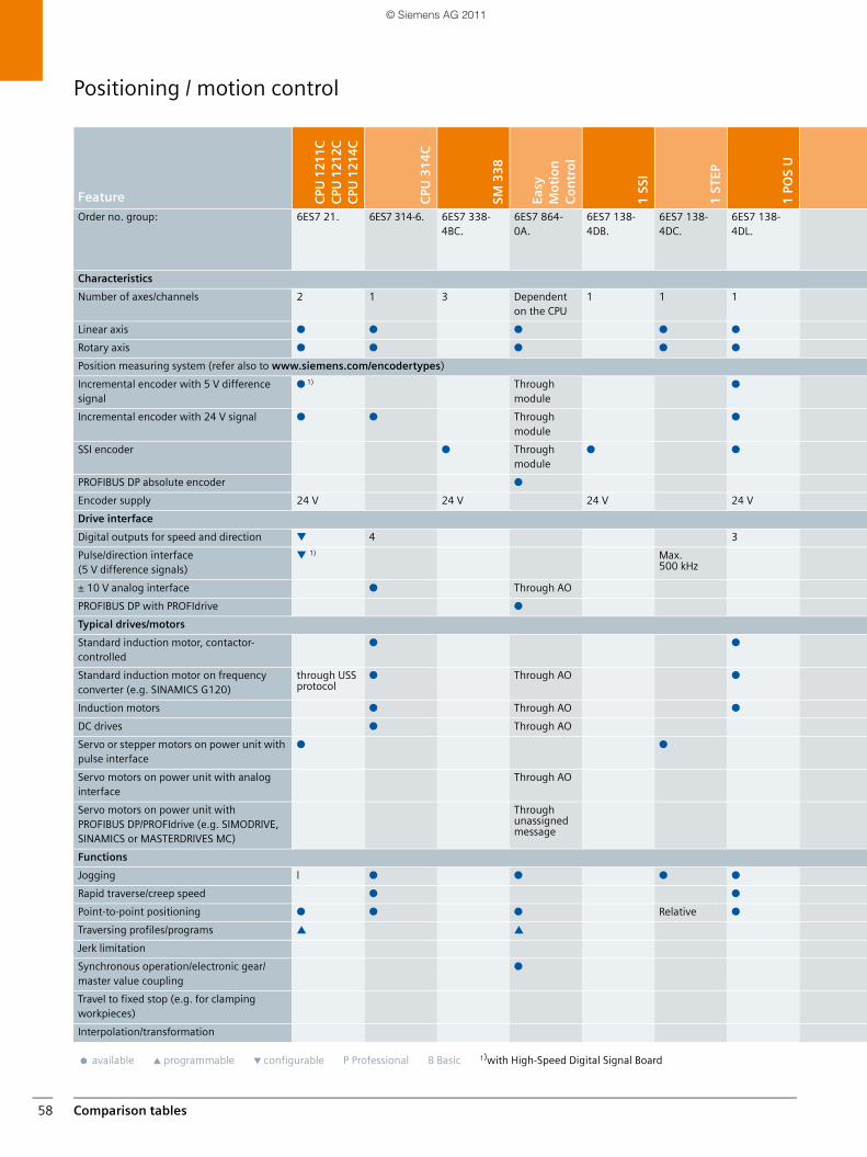
Comparison tables58
Positioning / motion control
Feature CPU
121
1CC
PU 1
212C
CPU
121
4C
CPU
31
4C
SM 3
38
Easy
M
oti
on
Co
ntr
ol
1 S
SI
1 S
TEP
1 P
OS
U
Order no. group: 6ES7 21. 6ES7 314-6. 6ES7 338-4BC.
6ES7 864-0A.
6ES7 138-4DB.
6ES7 138-4DC.
6ES7 138-4DL.
Characteristics
Number of axes/channels 2 1 3 Dependent on the CPU
1 1 1
Linear axis ● ● ● ● ●
Rotary axis ● ● ● ● ●
Position measuring system (refer also to www.siemens.com/encodertypes)
Incremental encoder with 5 V difference signal
● 1) Through module
●
Incremental encoder with 24 V signal ● ● Through module
●
SSI encoder ● Through module
● ●
PROFIBUS DP absolute encoder ●
Encoder supply 24 V 24 V 24 V 24 V
Drive interface
Digital outputs for speed and direction ▼ 4 3
Pulse/direction interface (5 V difference signals)
▼ 1) Max. 500 kHz
± 10 V analog interface ● Through AO
PROFIBUS DP with PROFIdrive ●
Typical drives/motors
Standard induction motor, contactor-controlled
● ●
Standard induction motor on frequency converter (e.g. SINAMICS G120)
through USS protocol
● Through AO ●
Induction motors ● Through AO ●
DC drives ● Through AO
Servo or stepper motors on power unit with pulse interface
● ●
Servo motors on power unit with analog interface
Through AO
Servo motors on power unit with PROFIBUS DP/PROFIdrive (e.g. SIMODRIVE, SINAMICS or MASTERDRIVES MC)
Through unassigned message
Functions
Jogging l ● ● ● ●
Rapid traverse/creep speed ● ●
Point-to-point positioning ● ● ● Relative ●
Traversing profiles/programs ▲ ▲
Jerk limitation
Synchronous operation/electronic gear/master value coupling
●
Travel to fixed stop (e.g. for clamping workpieces)
Interpolation/transformation
● available ▲ programmable ▼ configurable P Professional B Basic 1)with High-Speed Digital Signal Board
SIMATIC_Technology_04_2011_en.book Seite 58 Freitag, 25. März 2011 3:51 15
© Siemens AG 2011
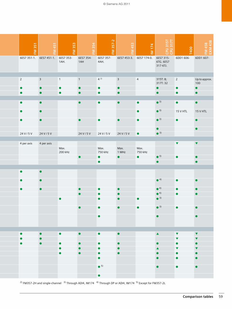
Comparison tables 59
FM 3
51
FM 4
51
FM 3
53
FM 3
54
FM 3
57
-2
FM 4
53
IM 1
74
CPU
31
5T
CPU
31
7T
T40
0
FM 4
58
EXM
43
8
6ES7 351-1. 6ES7 451-1. 6ES7 353-1AH.
6ES7 354-1AH
6ES7 357-4AH.
6ES7 453-3. 6ES7 174-0. 6ES7 315-6TG. 6ES7 317-6TJ.
6DD1 606- 6DD1 607-
2 3 1 1 4 2) 3 4 315T: 8; 317T: 32
2 Up to approx. 100
● ● ● ● ● ● ● ● ●
● ● ● ● ● ● ● ● ●
● ● ● ● ● ● ● 3) ● ●
● ● ● ● 3) 15 V HTL 15 V HTL
● ● ● ● ● ● ● 3) ● ●
● ●
24 V / 5 V 24 V / 5 V 24 V / 5 V 24 V / 5 V 24 V / 5 V ● ● 3)
4 per axis 4 per axis ▼ ▼
Max. 200 kHz
Max. 750 kHz
Max. 1 MHz
Max. 750 kHz
● ● ● ● ● 3) ● ●
● ● ●
● ●
● ● ● 4) ● ●
● ● ● ● ● ● 4) ● ●
● ● ● ● 4) ● ●
● ● ● ● ● 3)
● ● ● ● ● 3) ● ●
● ● ●
● ● ● ● ● ● ▲ ▼ ▼
● ● ▼ ▼
● ● ● ● ● ● ● ● ●
● ● ● ● ▲ ▼ ▼
● ● ● ● ● ● ●
● ● ● ●
● 5) ● ● ●
●
2) FM357-2H and single-channel 3) Through ADI4, IM174 4) Through DP or ADI4, IM174 5) Except for FM357-2L
SIMATIC_Technology_04_2011_en.book Seite 59 Freitag, 25. März 2011 3:51 15
© Siemens AG 2011
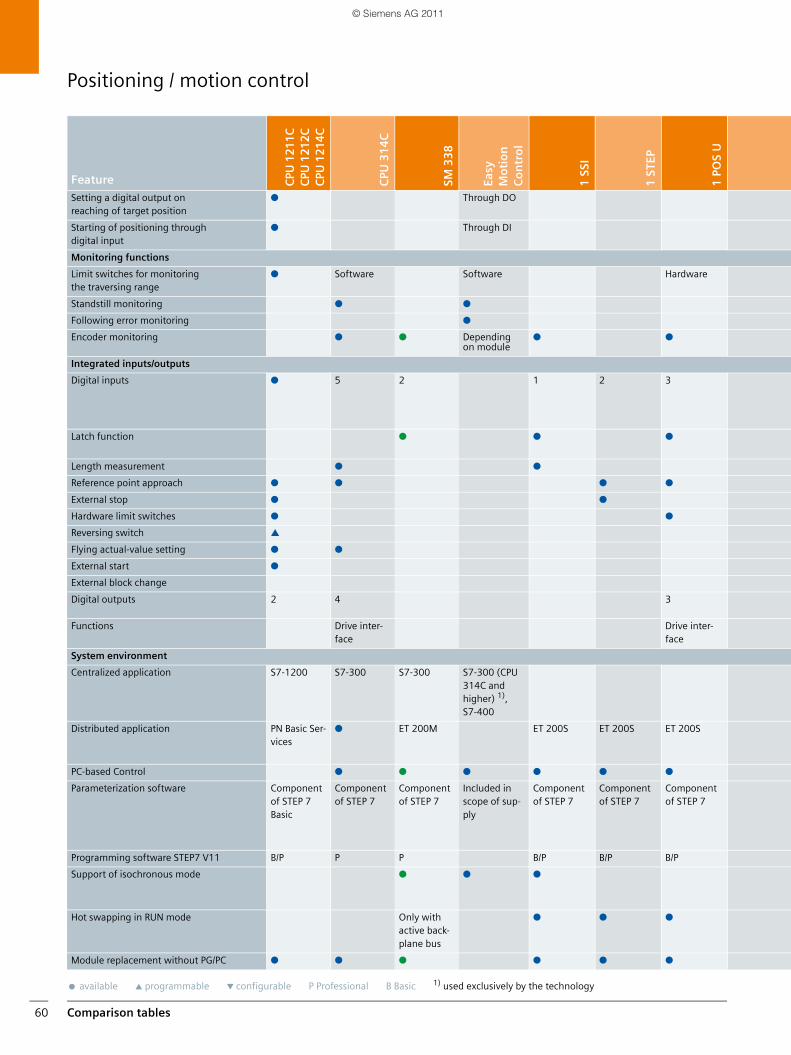
Comparison tables60
Positioning / motion control
Feature CPU
121
1CC
PU 1
212C
CPU
121
4C
CPU
31
4C
SM 3
38
Easy
M
oti
on
Co
ntr
ol
1 S
SI
1 S
TEP
1 P
OS
U
Setting a digital output on reaching of target position
● Through DO
Starting of positioning through digital input
● Through DI
Monitoring functions
Limit switches for monitoring the traversing range
● Software Software Hardware
Standstill monitoring ● ●
Following error monitoring ●
Encoder monitoring ● ● Depending on module
● ●
Integrated inputs/outputs
Digital inputs ● 5 2 1 2 3
Latch function ● ● ●
Length measurement ● ●
Reference point approach ● ● ● ●
External stop ● ●
Hardware limit switches ● ●
Reversing switch ▲
Flying actual-value setting ● ●
External start ●
External block change
Digital outputs 2 4 3
Functions Drive inter-face
Drive inter-face
System environment
Centralized application S7-1200 S7-300 S7-300 S7-300 (CPU 314C and higher) 1), S7-400
Distributed application PN Basic Ser-vices
● ET 200M ET 200S ET 200S ET 200S
PC-based Control ● ● ● ● ● ●
Parameterization software Component of STEP 7 Basic
Component of STEP 7
Component of STEP 7
Included in scope of sup-ply
Component of STEP 7
Component of STEP 7
Component of STEP 7
Programming software STEP7 V11 B/P P P B/P B/P B/P
Support of isochronous mode ● ● ●
Hot swapping in RUN mode Only with active back-plane bus
● ● ●
Module replacement without PG/PC ● ● ● ● ● ●
● available ▲ programmable ▼ configurable P Professional B Basic 1) used exclusively by the technology
SIMATIC_Technology_04_2011_en.book Seite 60 Freitag, 25. März 2011 3:51 15
© Siemens AG 2011
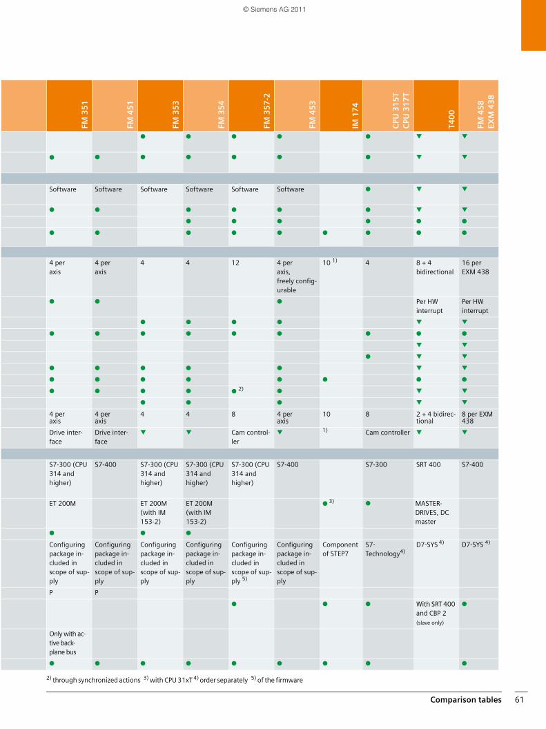
Comparison tables 61
FM 3
51
FM 4
51
FM 3
53
FM 3
54
FM 3
57
-2
FM 4
53
IM 1
74
CPU
31
5T
CPU
31
7T
T40
0
FM 4
58
EXM
43
8
● ● ● ● ● ▼ ▼
● ● ● ● ● ● ● ▼ ▼
Software Software Software Software Software Software ● ▼ ▼
● ● ● ● ● ● ▼ ▼
● ● ● ● ● ●
● ● ● ● ● ● ● ● ●
4 per axis
4 per axis
4 4 12 4 per axis, freely config-urable
10 1) 4 8 + 4 bidirectional
16 per EXM 438
● ● ● Per HW interrupt
Per HW interrupt
● ● ● ● ▼ ▼
● ● ● ● ● ● ● ● ●
▼ ▼
● ▼ ▼
● ● ● ● ● ▼ ▼
● ● ● ● ● ● ● ●
● ● ● ● ● 2) ● ▼ ▼
● ● ● ▼ ▼
4 per axis
4 per axis
4 4 8 4 per axis
10 8 2 + 4 bidirec-tional
8 per EXM 438
Drive inter-face
Drive inter-face
▼ ▼ Cam control-ler
▼ 1) Cam controller ▼ ▼
S7-300 (CPU 314 and higher)
S7-400 S7-300 (CPU 314 and higher)
S7-300 (CPU 314 and higher)
S7-300 (CPU 314 and higher)
S7-400 S7-300 SRT 400 S7-400
ET 200M ET 200M (with IM 153-2)
ET 200M (with IM 153-2)
● 3) ● MASTER-DRIVES, DC master
● ● ●
Configuring package in-cluded in scope of sup-ply
Configuring package in-cluded in scope of sup-ply
Configuring package in-cluded in scope of sup-ply
Configuring package in-cluded in scope of sup-ply
Configuring package in-cluded in scope of sup-ply 5)
Configuring package in-cluded in scope of sup-ply
Component of STEP7
S7-Technology4)
D7-SYS 4) D7-SYS 4)
P P
● ● ● With SRT 400 and CBP 2 (slave only)
●
Only with ac-tive back-plane bus
● ● ● ● ● ● ● ● ●
2) through synchronized actions 3) with CPU 31xT 4) order separately 5) of the firmware
SIMATIC_Technology_04_2011_en.book Seite 61 Freitag, 25. März 2011 3:51 15
© Siemens AG 2011
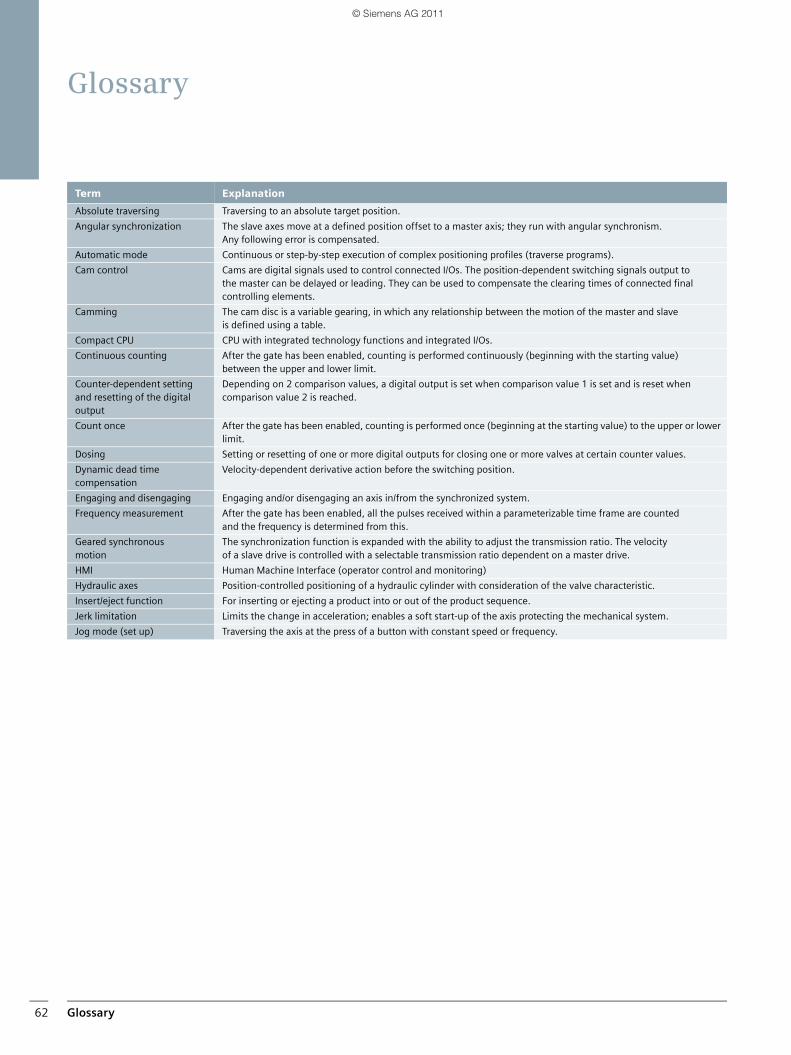
Glossary62
Glossary
Term Explanation
Absolute traversing Traversing to an absolute target position.
Angular synchronization The slave axes move at a defined position offset to a master axis; they run with angular synchronism. Any following error is compensated.
Automatic mode Continuous or step-by-step execution of complex positioning profiles (traverse programs).
Cam control Cams are digital signals used to control connected I/Os. The position-dependent switching signals output to the master can be delayed or leading. They can be used to compensate the clearing times of connected final controlling elements.
Camming The cam disc is a variable gearing, in which any relationship between the motion of the master and slave is defined using a table.
Compact CPU CPU with integrated technology functions and integrated I/Os.
Continuous counting After the gate has been enabled, counting is performed continuously (beginning with the starting value) between the upper and lower limit.
Counter-dependent setting and resetting of the digital output
Depending on 2 comparison values, a digital output is set when comparison value 1 is set and is reset when comparison value 2 is reached.
Count once After the gate has been enabled, counting is performed once (beginning at the starting value) to the upper or lower limit.
Dosing Setting or resetting of one or more digital outputs for closing one or more valves at certain counter values.
Dynamic dead time compensation
Velocity-dependent derivative action before the switching position.
Engaging and disengaging Engaging and/or disengaging an axis in/from the synchronized system.
Frequency measurement After the gate has been enabled, all the pulses received within a parameterizable time frame are counted and the frequency is determined from this.
Geared synchronous motion
The synchronization function is expanded with the ability to adjust the transmission ratio. The velocity of a slave drive is controlled with a selectable transmission ratio dependent on a master drive.
HMI Human Machine Interface (operator control and monitoring)
Hydraulic axes Position-controlled positioning of a hydraulic cylinder with consideration of the valve characteristic.
Insert/eject function For inserting or ejecting a product into or out of the product sequence.
Jerk limitation Limits the change in acceleration; enables a soft start-up of the axis protecting the mechanical system.
Jog mode (set up) Traversing the axis at the press of a button with constant speed or frequency.
SIMATIC_Technology_04_2011_en.book Seite 62 Freitag, 25. März 2011 3:51 15
© Siemens AG 2011
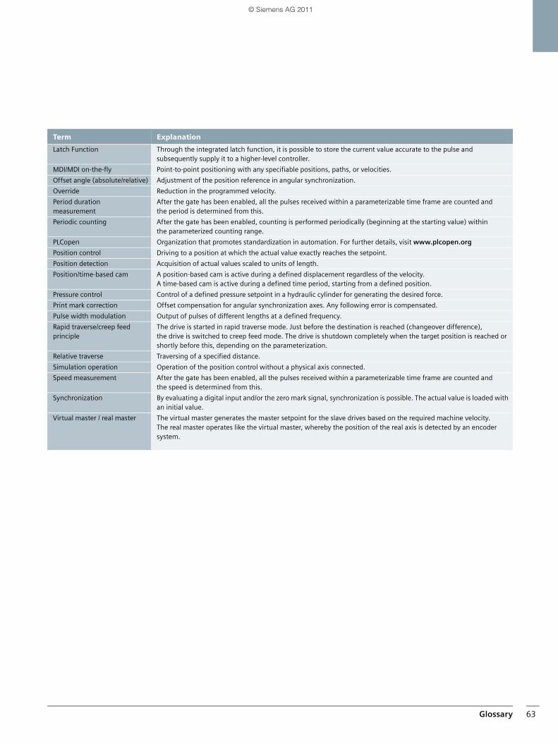
Glossary 63
Term Explanation
Latch Function Through the integrated latch function, it is possible to store the current value accurate to the pulse and subsequently supply it to a higher-level controller.
MDI/MDI on-the-fly Point-to-point positioning with any specifiable positions, paths, or velocities.
Offset angle (absolute/relative) Adjustment of the position reference in angular synchronization.
Override Reduction in the programmed velocity.
Period duration measurement
After the gate has been enabled, all the pulses received within a parameterizable time frame are counted andthe period is determined from this.
Periodic counting After the gate has been enabled, counting is performed periodically (beginning at the starting value) withinthe parameterized counting range.
PLCopen Organization that promotes standardization in automation. For further details, visit www.plcopen.org
Position control Driving to a position at which the actual value exactly reaches the setpoint.
Position detection Acquisition of actual values scaled to units of length.
Position/time-based cam A position-based cam is active during a defined displacement regardless of the velocity.A time-based cam is active during a defined time period, starting from a defined position.
Pressure control Control of a defined pressure setpoint in a hydraulic cylinder for generating the desired force.
Print mark correction Offset compensation for angular synchronization axes. Any following error is compensated.
Pulse width modulation Output of pulses of different lengths at a defined frequency.
Rapid traverse/creep feed principle
The drive is started in rapid traverse mode. Just before the destination is reached (changeover difference), the drive is switched to creep feed mode. The drive is shutdown completely when the target position is reached or shortly before this, depending on the parameterization.
Relative traverse Traversing of a specified distance.
Simulation operation Operation of the position control without a physical axis connected.
Speed measurement After the gate has been enabled, all the pulses received within a parameterizable time frame are counted and the speed is determined from this.
Synchronization By evaluating a digital input and/or the zero mark signal, synchronization is possible. The actual value is loaded with an initial value.
Virtual master / real master The virtual master generates the master setpoint for the slave drives based on the required machine velocity. The real master operates like the virtual master, whereby the position of the real axis is detected by an encoder system.
SIMATIC_Technology_04_2011_en.book Seite 63 Freitag, 25. März 2011 3:51 15
© Siemens AG 2011
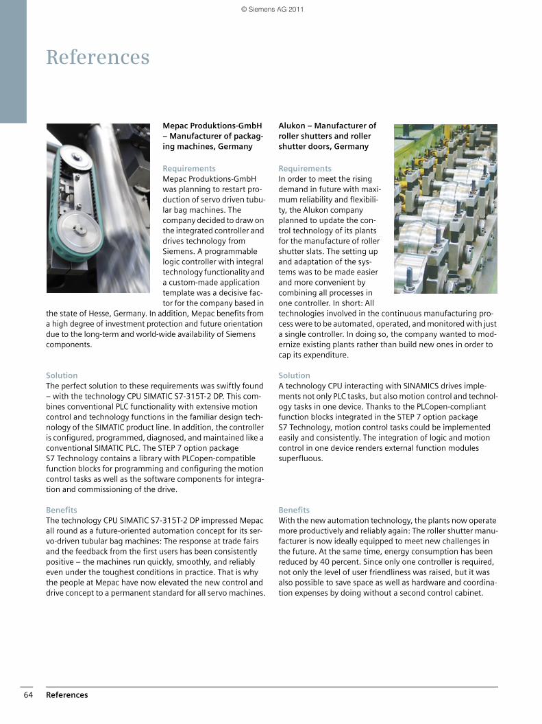
References64
References
Mepac Produktions-GmbH – Manufacturer of packag-ing machines, Germany
RequirementsMepac Produktions-GmbH was planning to restart pro-duction of servo driven tubu-lar bag machines. The company decided to draw on the integrated controller and drives technology from Siemens. A programmable logic controller with integral technology functionality and a custom-made application template was a decisive fac-tor for the company based in
the state of Hesse, Germany. In addition, Mepac benefits from a high degree of investment protection and future orientation due to the long-term and world-wide availability of Siemens components.
SolutionThe perfect solution to these requirements was swiftly found – with the technology CPU SIMATIC S7-315T-2 DP. This com-bines conventional PLC functionality with extensive motion control and technology functions in the familiar design tech-nology of the SIMATIC product line. In addition, the controller is configured, programmed, diagnosed, and maintained like a conventional SIMATIC PLC. The STEP 7 option package S7 Technology contains a library with PLCopen-compatible function blocks for programming and configuring the motion control tasks as well as the software components for integra-tion and commissioning of the drive.
BenefitsThe technology CPU SIMATIC S7-315T-2 DP impressed Mepac all round as a future-oriented automation concept for its ser-vo-driven tubular bag machines: The response at trade fairs and the feedback from the first users has been consistently positive – the machines run quickly, smoothly, and reliably even under the toughest conditions in practice. That is why the people at Mepac have now elevated the new control and drive concept to a permanent standard for all servo machines.
Alukon – Manufacturer of roller shutters and roller shutter doors, Germany
Requirements In order to meet the rising demand in future with maxi-mum reliability and flexibili-ty, the Alukon company planned to update the con-trol technology of its plants for the manufacture of roller shutter slats. The setting up and adaptation of the sys-tems was to be made easier and more convenient by combining all processes in one controller. In short: All technologies involved in the continuous manufacturing pro-cess were to be automated, operated, and monitored with just a single controller. In doing so, the company wanted to mod-ernize existing plants rather than build new ones in order to cap its expenditure.
SolutionA technology CPU interacting with SINAMICS drives imple-ments not only PLC tasks, but also motion control and technol-ogy tasks in one device. Thanks to the PLCopen-compliant function blocks integrated in the STEP 7 option package S7 Technology, motion control tasks could be implemented easily and consistently. The integration of logic and motion control in one device renders external function modules superfluous.
BenefitsWith the new automation technology, the plants now operate more productively and reliably again: The roller shutter manu-facturer is now ideally equipped to meet new challenges in the future. At the same time, energy consumption has been reduced by 40 percent. Since only one controller is required, not only the level of user friendliness was raised, but it was also possible to save space as well as hardware and coordina-tion expenses by doing without a second control cabinet.
SIMATIC_Technology_04_2011_en.book Seite 64 Freitag, 25. März 2011 3:51 15
© Siemens AG 2011
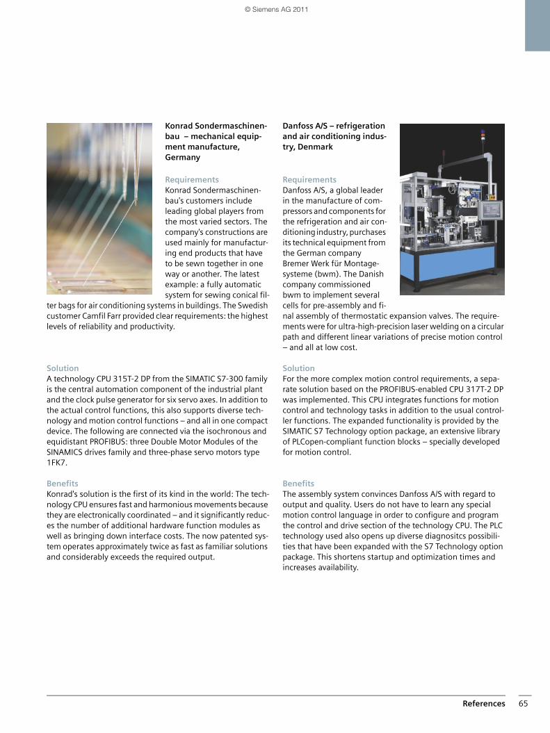
References 65
Konrad Sondermaschinen-bau – mechanical equip-ment manufacture, Germany
RequirementsKonrad Sondermaschinen-bau's customers include leading global players from the most varied sectors. The company's constructions are used mainly for manufactur-ing end products that have to be sewn together in one way or another. The latest example: a fully automatic system for sewing conical fil-
ter bags for air conditioning systems in buildings. The Swedish customer Camfil Farr provided clear requirements: the highest levels of reliability and productivity.
Solution A technology CPU 315T-2 DP from the SIMATIC S7-300 family is the central automation component of the industrial plant and the clock pulse generator for six servo axes. In addition to the actual control functions, this also supports diverse tech-nology and motion control functions – and all in one compact device. The following are connected via the isochronous and equidistant PROFIBUS: three Double Motor Modules of the SINAMICS drives family and three-phase servo motors type 1FK7.
BenefitsKonrad's solution is the first of its kind in the world: The tech-nology CPU ensures fast and harmonious movements because they are electronically coordinated – and it significantly reduc-es the number of additional hardware function modules as well as bringing down interface costs. The now patented sys-tem operates approximately twice as fast as familiar solutions and considerably exceeds the required output.
Danfoss A/S – refrigeration and air conditioning indus-try, Denmark
Requirements Danfoss A/S, a global leader in the manufacture of com-pressors and components for the refrigeration and air con-ditioning industry, purchases its technical equipment from the German company Bremer Werk für Montage-systeme (bwm). The Danish company commissioned bwm to implement several cells for pre-assembly and fi-nal assembly of thermostatic expansion valves. The require-ments were for ultra-high-precision laser welding on a circular path and different linear variations of precise motion control – and all at low cost.
Solution For the more complex motion control requirements, a sepa-rate solution based on the PROFIBUS-enabled CPU 317T-2 DP was implemented. This CPU integrates functions for motion control and technology tasks in addition to the usual control-ler functions. The expanded functionality is provided by the SIMATIC S7 Technology option package, an extensive library of PLCopen-compliant function blocks – specially developed for motion control.
BenefitsThe assembly system convinces Danfoss A/S with regard to output and quality. Users do not have to learn any special motion control language in order to configure and program the control and drive section of the technology CPU. The PLC technology used also opens up diverse diagnositcs possibili-ties that have been expanded with the S7 Technology option package. This shortens startup and optimization times and increases availability.
SIMATIC_Technology_04_2011_en.book Seite 65 Freitag, 25. März 2011 3:51 15
© Siemens AG 2011
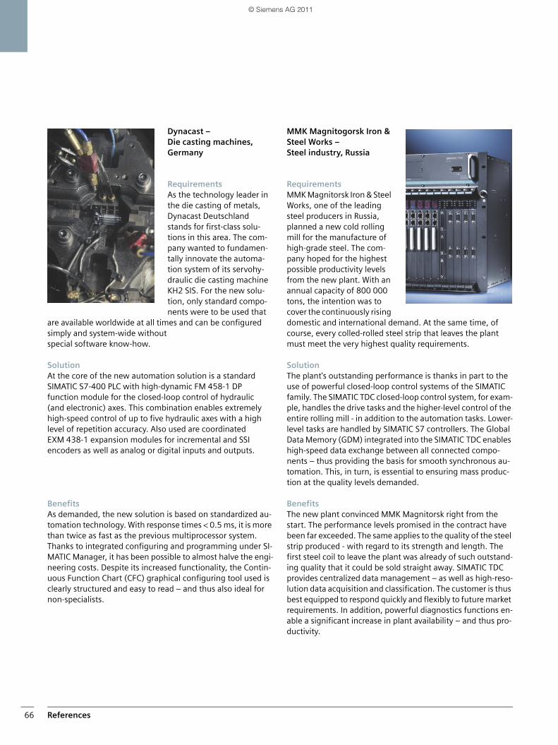
References66
Dynacast – Die casting machines, Germany
Requirements As the technology leader in the die casting of metals, Dynacast Deutschland stands for first-class solu-tions in this area. The com-pany wanted to fundamen-tally innovate the automa-tion system of its servohy-draulic die casting machine KH2 SIS. For the new solu-tion, only standard compo-nents were to be used that
are available worldwide at all times and can be configured simply and system-wide without special software know-how.
Solution At the core of the new automation solution is a standard SIMATIC S7-400 PLC with high-dynamic FM 458-1 DP function module for the closed-loop control of hydraulic (and electronic) axes. This combination enables extremely high-speed control of up to five hydraulic axes with a high level of repetition accuracy. Also used are coordinated EXM 438-1 expansion modules for incremental and SSI encoders as well as analog or digital inputs and outputs.
BenefitsAs demanded, the new solution is based on standardized au-tomation technology. With response times < 0.5 ms, it is more than twice as fast as the previous multiprocessor system. Thanks to integrated configuring and programming under SI-MATIC Manager, it has been possible to almost halve the engi-neering costs. Despite its increased functionality, the Contin-uous Function Chart (CFC) graphical configuring tool used is clearly structured and easy to read – and thus also ideal for non-specialists.
MMK Magnitogorsk Iron & Steel Works – Steel industry, Russia
RequirementsMMK Magnitorsk Iron & Steel Works, one of the leading steel producers in Russia, planned a new cold rolling mill for the manufacture of high-grade steel. The com-pany hoped for the highest possible productivity levels from the new plant. With an annual capacity of 800 000 tons, the intention was to cover the continuously rising domestic and international demand. At the same time, of course, every colled-rolled steel strip that leaves the plant must meet the very highest quality requirements.
SolutionThe plant's outstanding performance is thanks in part to the use of powerful closed-loop control systems of the SIMATIC family. The SIMATIC TDC closed-loop control system, for exam-ple, handles the drive tasks and the higher-level control of the entire rolling mill - in addition to the automation tasks. Lower-level tasks are handled by SIMATIC S7 controllers. The Global Data Memory (GDM) integrated into the SIMATIC TDC enables high-speed data exchange between all connected compo-nents – thus providing the basis for smooth synchronous au-tomation. This, in turn, is essential to ensuring mass produc-tion at the quality levels demanded.
Benefits The new plant convinced MMK Magnitorsk right from the start. The performance levels promised in the contract have been far exceeded. The same applies to the quality of the steel strip produced - with regard to its strength and length. The first steel coil to leave the plant was already of such outstand-ing quality that it could be sold straight away. SIMATIC TDC provides centralized data management – as well as high-reso-lution data acquisition and classification. The customer is thus best equipped to respond quickly and flexibly to future market requirements. In addition, powerful diagnostics functions en-able a significant increase in plant availability – and thus pro-ductivity.
SIMATIC_Technology_04_2011_en.book Seite 66 Freitag, 25. März 2011 3:51 15
© Siemens AG 2011
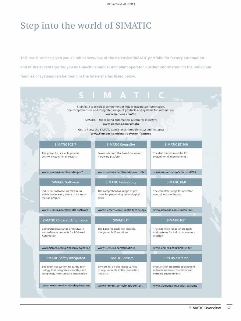
Step into the world of SIMATIC
SIMATIC is a principal component of Totally Integrated Automation, the comprehensive and integrated range of products and systems for automation:
www.siemens.com/tia
SIMATIC – the leading automation system for industry: www.siemens.com/simatic
Get to know the SIMATIC consistency through its system features:www.siemens.com/simatic-system-features
S I M A T I C
This brochure has given you an initial overview of the extensive SIMATIC portfolio for factory automation –
and of the advantages for you as a machine builder and plant operator. Further information on the individual
families of systems can be found in the Internet sites listed below.
SIMATIC HMI
SIMATIC ET 200
SIMATIC PC-based Automation
SIMATIC Technology
SIMATIC Sensors SIPLUS extreme
SIMATIC NETSIMATIC IT
SIMATIC PCS 7 SIMATIC Controller
SIMATIC Software
The complete range for opera tor control and monitoring
Comprehensive range of hardware and software products for PC-based Automation
The comprehensive range of pro-ducts for performing technological tasks
Sensors for an enormous variety of requirements in the production industry
Products for industrial applications in harsh ambient conditions and extreme environments
The seamless system for safety tech-nology that integrates smoothly and completely into standard automation
The extensive range of products and systems for industrial commu-nication
The basis for customer-specific, integrated MES solutions
Industrial software for maximum efficiency in every phase of an auto-mation project
The distributed, modular I/O system for all requirements
www.siemens.com/simatic-et200
Powerful controller based on various hardware platforms
www.siemens.com/simatic-controller
The powerful, scalable process control system for all sectors
www.siemens.com/simatic-pcs7
SIMATIC Safety Integrated
www.siemens.com/simatic-software www.siemens.com/simatic-technology www.siemens.com/simatic-hmi
www.siemens.com/pc-based-automation www.siemens.com/simatic-it www.siemens.com/simatic-net
www.siemens.com/simatic-safety-integrated www.siemens.com/simatic-sensors www.siemens.com/siplus-extreme
SIMATIC Overview 67
67_en_SIMATIC_Mapping_Fert_industie.indd 167_en_SIMATIC_Mapping_Fert_industie.indd 1 25.03.2011 16:30:0625.03.2011 16:30:06
© Siemens AG 2011
The information provided in this brochure contains descriptions or characteristics of performance which in case of actual use do not always apply as described or which may change as a result of further development of the products. An obligation to provide the respective characteristics shall only exist if expressly agreed in the terms of contract. Availability and technical specifications are subject to change without prior notice.All product designations may be trademarks or product names of Siemens AG or supplier companies whose use by third parties for their own purposes could violate the rights of the owners.
Get more information
SIMATIC Technologywww.siemens.com/simatic-technology
Totally Integrated Automationwww.siemens.com/tia
SIMATIC Technology Newsletterwww.siemens.com/automation/newsletter
SIMATIC Guide manuals:www.siemens.com/simatic-docu
You can find other publications on the topic of SIMATIC at: www.siemens.com/simatic/printmaterial
Service & Support portal:www.siemens.com/automation/support
SIMATIC contacts www.siemens.com/automation/partner
In the Industry Mall you can place orders electronically via the Internet: www.siemens.com/industrymall
Siemens AGIndustry SectorPostfach 48 4890026 NÜRNBERGGERMANY
Subject to change without prior noticeOrder No.: 6ZB5310-0MN02-0BA73P.8301.27.03 / Dispo 26100BR 0411 2. ROT 68 EnPrinted in Germany © Siemens AG 2011
www.siemens.com/automation
SIMATIC_Technology_04_2011_en.book Seite 67 Freitag, 25. März 2011 3:51 15
© Siemens AG 2011