Embed Size (px)
Citation preview
Product Information Bulletin
This bulletin contains important informationon your PC BI10/FI10/FI15.
SIMATIC
PC BI10/FI10/FI15
C79000-Z7076-C772-02

This product information bulletin contains notices which you should observe to ensure your ownpersonal safety, as well as to protect the product and connected equipment. These notices arehighlighted in the manual by a warning triangle and are marked as follows according to the levelof danger:
!Warning
indicates that death, severe personal injury, or substantial property damage can result if properprecautions are not taken.
!Caution
indicates that minor personal injury or property damage can result if proper precautions are nottaken.
Note
draws your attention to particularly important information on the product, handling the product, orto a particular part of the documentation.
Please observe the following:
Note
You can set up and operate your programming device in conjunction with the following instructions.You should only connect external devices and work with memory cards in conjunction with theTechnical Description.
Only qualified personnel should be allowed to install and work on this equipment using theTechnical Description. Qualified persons are defined as persons who are authorized tocommission, to ground, and to tag equipment, systems, and circuits in accordance with establishedsafety practices and standards.
!Warning
This device may only be used for the applications described in the catalog or technical description,and only in connection with devices or components from other manufacturers which have been approved or recommended by Siemens.
This product can only function correctly and safely if it is transported, stored, and set up carefullyand correctly, and operated and maintained as recommended.
SIMATIC�, SIMATIC NET� and SIMATIC HMI � are registered trademarks of SIEMENS AG.
The reproduction, transmission or use of this document or its contents isnot permitted without express written authority. Offenders will be liable fordamages. All rights, including rights created by patent grant or registrationof a utility model or design, are reserved.
We have checked the contents of this manual for agreement with thehardware and software described. Since deviations cannot be precludedentirely, we cannot guarantee full agreement. However, the data in thismanual are reviewed regularly and any necessary corrections included insubsequent editions. Suggestions for improvement are welcomed.��Siemens AG 1998Subject to change without prior notice
Disclaimer of LiabilityCopyright � Siemens AG 1998 All Rights Reserved
Siemens AGBereich Automatisierungs- und AntriebstechnikGeschaeftsgebiet Industrie-AutomatisierungssystemePostfach 4848, D-Nuernberg
C79000�Z7076�C772Siemens Aktiengesellschaft
Safety Guidelines
Correct Usage
Trademarks
3PC BI10/FI10/FI15 Product Information BulletinC79000-Z7076-C772-02
Safety Instructions
This chapter provides you with safety instructions which you must followwhen operating your PC and its components.
This device conforms to the pertinent safety requirements according to IEC,VDE, EN, UL, and CSA. If you have questions about the admissibility ofinstallation in the selected environment, please contact one of our servicedepartments. You will find a list of addresses in Chapter 5.
Chapter Overview
1
4PC BI10/FI10/FI15 Product Information Bulletin
C79000-Z7076-C772-02
1.1 General Notes
We recommend that you transport the device only in the original packaging(protection against shock and impact).
Condensation can occur if the device is transported from a cold environmentto the operating area. The device must be dry prior to startup. You musttherefore provide an acclimatization time of at least four hours.
During installation and prior to operation, please read the information onambient conditions provided in the section entitled “TechnicalSpecifications” as well as the information concerning installation of thedevice presented in Section 2.1 of this manual.
The device must be installed in such a way that it presents no danger of anykind (for instance if it is overturned).
Make sure that the ventilation slots are open so that a sufficient amount of aircan be drawn in to cool the housing interior.
If the PC is to be permanently installed (in a rack, for example), the driveprotection cover in front of the drives on the front side must be kept closedfor safety reasons (fire protection according to UL 1950/EN 60950). Thedrive protection cover may be opened only to service the drives. Removal ofthe cover is not permitted.
!Warning
When installing the systems, the permissible mounting positions must beobserved (see Section 2.2.1).
Installation in an impermissible mounting position invalidates certificationin accordance with UL 1950 and EN 6095.
Check to make sure that the rated voltage for the device is the same as thelocal mains voltage.
This device is equipped with a safety-tested power supply cable, and may beconnected only to a socket outlet with earthing contact.
Make sure that the socket outlet on the device or the grounding contact forthe building wiring systems is freely accessible and located as near to thedevice as possible.
The PCs have no power switch. To completely disconnect one of these PCsfrom the mains power, you must pull the plug. This connection must beeasily accessible. For cabinet mounting, a central disconnector must beprovided.
Lay the cables so that no one can step on or trip over them. When connectingthe device, carefully observe the pertinent information given in Chapter 2.
Never connect or disconnect power cables or data transmission lines during athunderstorm.
Transport
Installation
Power Connection
5PC BI10/FI10/FI15 Product Information BulletinC79000-Z7076-C772-02
In an emergency situation (for instance damage to housing, operatingelements or power cable, penetration of liquids or foreign bodies), pull thepower plug and contact the authorized service department.
The PC must be switched off before connecting/disconnecting I/O devices(keyboard, mouse, printer, etc.). Failure to do so can result in damage to thePC.
For operation in Canada and the United States, use CSA or UL-listed powercables.
For the USA and Canada:Both a UL approval and a CSA marking are required for the cable in theUSA and Canada. The connector must comply with the NEMA 5-15specification.
For 120 V devicesA flexible cable with UL approval and CSA marking and the followingfeatures must be used: SJT design with three conductors, at least 18 AWGcross-section, a maximum length of 4.5 meters and parallel grounding-typeplug (15 A, at least 125 V).
For 240 V devices (used in Germany)A flexible cable with UL approval and CSA marking and the followingfeatures must be used: SJT design with three conductors, at least 18 AWGcross-section, a maximum length of 4.5 meters and Tandem ground-type plug(15 A, at least 250 V).
For 230 V devices (outside the USA)A flexible cable with the following features must be used: At least 18 AWGcross-section and grounding-type plug (15 A, 250 V). The cables mustconform to the relevant safety guidelines of the country in which they areinstalled and bear the specified markings.
The device is intended for connection to grounded power supply systems (TNnetworks to VDE 0100 Part 300 or IEC 364-3).
No provision is made for connection to non-grounded orimpedance-grounded power supply systems (IT networks).
The power cable should comply with the safety guidelines of the countryconcerned.
Only authorized personnel are permitted to repair the device. Unauthorizedopening and improper repairs on the device can result in significant danger tothe user.
Always pull the power plug before opening the device.
Install only system expansion equipment intended for this computer. If youinstall other expansion equipment, you can damage the system or violate thesafety requirements and regulations for radio interference suppression.Contact your technical customer service or dealer to find out whichexpansion devices may be safely installed.
Installation or exchange of system expansions which result in defects to yourPC invalidate the warranty.
Country-SpecificNotes
Repairs
6PC BI10/FI10/FI15 Product Information Bulletin
C79000-Z7076-C772-02
Only authorized service personnel may remove or replace the power supplyunit.
The device is equipped with a battery, which is located on the mother board.Batteries may be replaced by service personnel only. Please refer to thedocumentation for the CPU module.
Dispose of used batteries in accordance with local regulations for specialwaste.
!Caution
Improper replacement of the battery poses danger of explosion. The batterymust be replaced only with an identical battery or a battery typerecommended by the manufacturer. Dispose of used batteries in accordancewith the manufacturer’s recommendations.
Modules containing electrostatically sensitive devices (ESDs) can beidentified by the following label:
The following guidelines must always be observed and carefully followedwhen handling modules equipped with electrostatically sensitive devices:� Always discharge your body before handling modules equipped with
ESDs (for example by touching a grounded object).� Devices and tools you use must be free of static electricity.� Always pull the power plug before connecting or disconnecting modulescontaining ESDs.� Touch modules fitted with ESDs by their edges only.� Never touch wiring posts or printed conductors on modules containingESDs.
Battery
ESD Guidelines
7PC BI10/FI10/FI15 Product Information BulletinC79000-Z7076-C772-02
1.2 Notes on the CE Symbol
The following applies to the SIMATIC product described in this manual:
This product fulfills the requirements of EC directive 89/336/EEC on“Electromagnetic Compatibility,” and is designed for the following fields ofapplication as per the CE marking:
Field of Application Requirement ForEmitted
InterferenceNoise Immunity
Residential, commercial and smallbusinesses EN 50081-1: 1992 EN 50082-1: 1992
Industrial EN 50081-2: 1993 EN 50082-2: 1995
This product fulfills the requirements of EC directive 73/23/EEC on “LowVoltage Directive.” Observance of this standard was tested toEN60950:A4:1997.
In accordance with the above-mentioned EU directives, the EC declarationsof conformity and the associated documentation are held at the disposal ofthe competent authorities at the address below:
Siemens AG
Bereich Automatisierungs- und Antriebstechnik
A&D AS E 4
Postfach 1963
D–92209 Amberg
Products which do not carry the CE marking fulfill the requirements andstandards as described in the chapter entitled “Technical Specifications.”
The installation guidelines and safety instructions discussed in the manualmust be observed on startup and during operation.
EC Directive
Low VoltageDirective
Declarations ofConformity
Observing theInstallationGuidelines
8PC BI10/FI10/FI15 Product Information Bulletin
C79000-Z7076-C772-02
1.3 Approvals for the USA and Canada
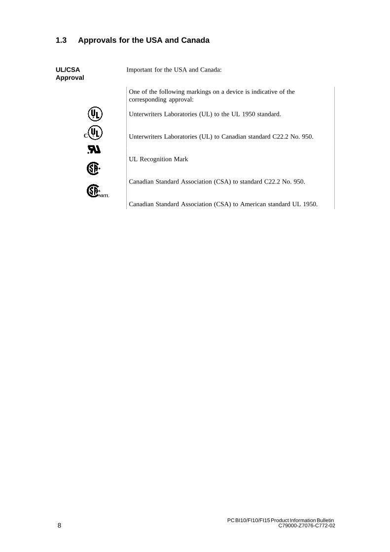
Important for the USA and Canada:
One of the following markings on a device is indicative of thecorresponding approval:
Unterwriters Laboratories (UL) to the UL 1950 standard.
Unterwriters Laboratories (UL) to Canadian standard C22.2 No. 950.
UL Recognition Mark
Canadian Standard Association (CSA) to standard C22.2 No. 950.
Canadian Standard Association (CSA) to American standard UL 1950.
UL/CSA Approval
C
NRTL

9PC BI10/FI10/FI15 Product Information BulletinC79000-Z7076-C772-02
1.3.1 FCC Approval for USA and Canada
Federal Communications CommissionRadio Frequency Interference Statement
This equipment has been tested and found to comply with the limits for a Class Adigital device, pursuant to Part 15 of the FCC Rules. These limits are designed toprovide reasonable protection against harmful interference when the equipment isoperated in a commercial environment. This equipment generates, uses, and can radiateradio frequency energy and, if not installed and used in accordance with the instructionmanual, may cause harmful interference to radio communications. Operation of thisequipment in a residential area is likely to cause harmful interference in which case theuser will be required to correct the interference at his own expense.
Shielded Cables
Shielded cables must be used with this equipment to maintain compliance with FCCregulations.
ModificationsChanges or modifications not expressly approved by the manufacturer could void theuser’s authority to operate the equipment.
Conditions of Operations
This device complies with Part 15 of the FCC Rules. Operation is subject to thefollowing two conditions: (1) this device may not cause harmful interference, and (2)this device must accept any interference received, including interference that maycause undesired operation.
Canadian Notice
This equipment does not exceed the Class A limits for radiated emissions as describedin the Radio Interference Regulations of the Canadian Department ofCommunications.
Avis Canadien
Le présent appareil numérique n’émet pas de bruits radioélectriques dépassant leslimites applicables aux appareils numériques de la Classe A prescrites dans leRéglement sur le brouillage radioélectrique édicté par le Ministère desCommunications du Canada.
10PC BI10/FI10/FI15 Product Information Bulletin
C79000-Z7076-C772-02
1.4 Technical Specifications
DimensionsSIMATIC PC FI10
(W x H x D in mm) 330 x 290 x 120 front(305 x 265 cutout)
DimensionsSIMATIC PC BI10
(W x H x D in mm) 295 x 235 x 100
DimensionsSIMATIC PC FI15
(W x H x D in mm) 455 x 335 x 120 front(305 x 420 cutout)
Weight of SIMATIC PC FI10 Approx. 7.5 kg
Weight of SIMATIC PC BI10 Approx. 5 kg
Weight of SIMATIC PC FI15 Approx. 8 kg
Line voltage 120 - 240 VAC tolerance range (85 to 265 VAC)Line voltage frequency 50/60 Hz (47 to 63 Hz)
Brief voltage interruption acc. to NAMUR Max. 20 ms at full load
Max. power consumption < 120 W, rated current 1.4/0.8A at 120/240 V
Max. current delivery (internal) 5V
8 A
12V1.5A(2.5A max 10s)
3.3V
2.2A
-12V
0.2 A
5V isolated*0.24A
Degree of protection for SIMATIC PC FI10 Front IP65, otherwise IP20
Degree of protection for SIMATIC PC FI15 Front IP65 (with drive cover closed)
Degree of protection for SIMATIC PC BI10 Front IP20
SafetyProtection class Protection class I to VDE 0106 T1;1982 (IEC 536)Safety requirements EN60950 corr. to
IEC 950 A4: 1996 corr. toVDE 0805 A4:1997
Electromagnetic Compatibility (EMC)Emitted interference EN 55022 Class B
Noise immunity:Line-fed interference on supply lines
+- 2 kV (to IEC 1000-4-4:1995; burst)+- 1 kV (to IEC 1000-4-5:1995; surge symm)+- 2 kV (to IEC 1000-4-5:1995; surge unsymm)
Noise immunity on signal lines +- 1 kV (to IEC 1000-4-4:1995; burst; length < 3m)+- 2 kV (to IEC 1000-4-4:1995; burst; length > 3m)+- 1 kV (to IEC 1000-4-4:1995; surge symm;
length > 3m)+- 2 kV (to IEC 1000-4-4:1995; surge unsymm;
length > 3m)Noise immunity to discharges of static electricity +- 6 kV contact discharge (to IEC 1000-4-2:1995)
+- 8 kV air discharge (to IEC 1000-4-2:1995)Noise immunity to high-frequency radiation 10 V/m 80-1000 Mhz, 80% AM (to ENV 50140:1993)
10 V/m 900 Mhz, 50% ED (to ENV 50204:1995)Ambient ConditionsTemperature
- operation- storage/transport- gradient
Tested to DIN EN 60068-2-2, DIN IEC 68-2-1, DIN IEC 68-2-14
+ 5°C to +45°C- 20°C to +60°CMax. 10 degrees C/h (no condensation)
Relative humidity
- operation- storage/transport
Tested to DIN IEC 68-2-3, DIN IEC 68-2-30, DIN IEC 68-2-56
5 % to 85 % at 25°C (no condensation)5 % to 95 % at 25°C (no condensation)
11PC BI10/FI10/FI15 Product Information BulletinC79000-Z7076-C772-02
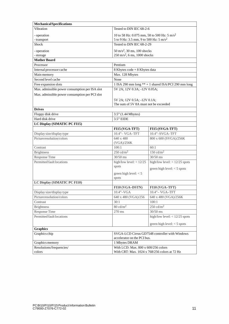
Mechanical SpecificationsVibration
- operation- transport
Tested to DIN IEC 68-2-6
10 to 58 Hz: 0.075 mm, 58 to 500 Hz: 5 m/s2
5 to 9 Hz: 3.5 mm, 9 to 500 Hz: 5 m/s2
Shock
- operation- storage
Tested to DIN IEC 68-2-29
50 m/s2, 30 ms, 100 shocks250 m/s2, 6 ms, 1000 shocks
Mother BoardProcessor PentiumInternal processor cache 8 Kbytes code + 8 Kbytes data
Main memory Max. 128 Mbytes
Second level cache None
Free expansion slots 1 ISA 290 mm long ** + 1 shared ISA/PCI 290 mm longMax. admissible power consumption per ISA slot
Max. admissible power consumption per PCI slot
5V 2A; 12V 0.3A; -12V 0.05A;
5V 2A; 12V 0.5A; -12V 0.1A;The sum of 5V 8A must not be exceeded
DrivesFloppy disk drive 3.5” (1.44 Mbytes)Hard disk drive 3.5” EIDE
LC Display (SIMATIC PC FI15)FI15 (VGA-TFT) FI15 (SVGA-TFT)
Display size/display type 10.4”– VGA–TFT 10.4”–SVGA–TFTPicture resolution/colors 640 x 480
(VGA)/256K800 x 600 (SVGA)/256K
Contrast 100:1 60:1
Brightness 250 cd/m2 150 cd/m2
Response Time 30/50 ms 30/50 ms
Permitted fault locations high/low level: < 12/25spots
green high level: < 5spots
high/low level: < 12/25 spots
green high level: < 5 spots
LC Display (SIMATIC PC FI10)FI10 (VGA–DSTN) FI10 (VGA–TFT)
Display size/display type 10.4”–VGA 10.4”– VGA–TFT
Picture resolution/colors 640 x 480 (VGA)/256 640 x 480 (VGA)/256K
Contrast 30:1 100:1
Brightness 80 cd/m2 250 cd/m2
Response Time 270 ms 30/50 ms
Permitted fault locations high/low level: < 12/25 spots
green high level: < 5 spots
GraphicsGraphics chip SVGA-LCD Cirrus GD7548 controller with Windows
accelerator on the PCI bus.Graphics memory 1 Mbytes DRAM
Resolutions/frequencies/colors
With LCD: Max. 800 x 600/256 colorsWith CRT: Max. 1024 x 768/256 colors at 72 Hz
12PC BI10/FI10/FI15 Product Information Bulletin
C79000-Z7076-C772-02
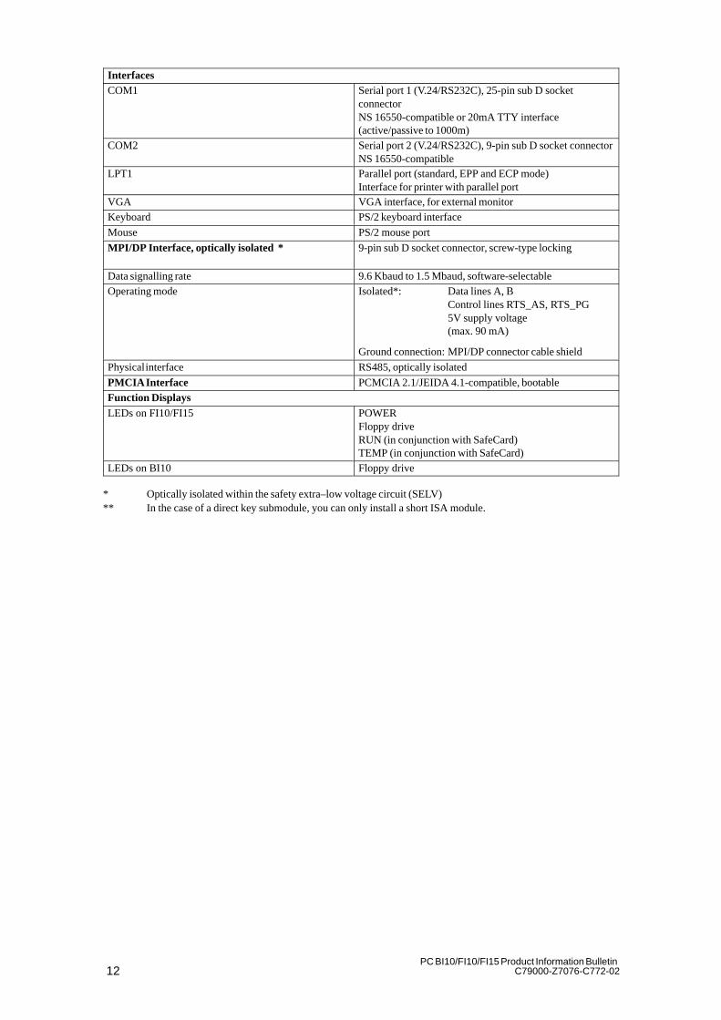
InterfacesCOM1 Serial port 1 (V.24/RS232C), 25-pin sub D socket
connectorNS 16550-compatible or 20mA TTY interface(active/passive to 1000m)
COM2 Serial port 2 (V.24/RS232C), 9-pin sub D socket connectorNS 16550-compatible
LPT1 Parallel port (standard, EPP and ECP mode)Interface for printer with parallel port
VGA VGA interface, for external monitorKeyboard PS/2 keyboard interface
Mouse PS/2 mouse port
MPI/DP Interface, optically isolated * 9-pin sub D socket connector, screw-type locking
Data signalling rate 9.6 Kbaud to 1.5 Mbaud, software-selectableOperating mode Isolated*: Data lines A, B
Control lines RTS_AS, RTS_PG5V supply voltage(max. 90 mA)
Ground connection: MPI/DP connector cable shield
Physical interface RS485, optically isolated
PMCIA Interface PCMCIA 2.1/JEIDA 4.1-compatible, bootableFunction DisplaysLEDs on FI10/FI15 POWER
Floppy driveRUN (in conjunction with SafeCard)TEMP (in conjunction with SafeCard)
LEDs on BI10 Floppy drive
* Optically isolated within the safety extra–low voltage circuit (SELV)** In the case of a direct key submodule, you can only install a short ISA module.
13PC BI10/FI10/FI15 Product Information BulletinC79000-Z7076-C772-02
Starting Up your PC
In this chapter, you will learn:� What to consider when installing your PC� Which interface port to use for connecting standard I/Os and� How to connect your PC to the mains voltage.
Chapter Overview
2

14PC BI10/FI10/FI15 Product Information Bulletin
C79000-Z7076-C772-02
2.1 Unpacking and Checking the Delivered Components
Proceed as follows to unpack your PC:
1. Remove the packaging.
2. Do not throw the original packaging away. Keep it in case you have totransport your PC at some time in the future.
3. Please be sure to keep the enclosed documentation. It belongs to thedevice and you will need it to put your PC into operation (see Chapter 3).
Proceed as follows:
1. Check the contents of the consignment using the supplement for deviceconfiguration.
2. Check the packaging and the package contents for any visible damage.
3. Inform your dealer immediately if there is any damage or if there is adiscrepancy between the packing list and the package contents.
Your SIMATIC PC is suitable for installation in consoles, switchgearcubicles, and control panels. For detailed information, see Sections 2.2.1,2.2.2, and 2.2.3.
Unpacking
Checking theContents
Setting Up YourPC
15PC BI10/FI10/FI15 Product Information BulletinC79000-Z7076-C772-02
2.2 Installation
Please observe the following when installing your SIMATIC PC:� Position the PC so as to avoid reflections on the screen as much aspossible.� Base your choice of mounting height on the position of your monitor,which should always be at an optimal height for the operator.� Do not expose your PC to direct sunlight.� Do not install the PC in such a way that the ventilation slots in the PChousing are covered.� The cabinet or control panel in which you install the PC should alwaysprovide sufficient space for proper air circulation.
!Warning
Avoid extreme environmental conditions whenever possible. Protect yourSIMATIC PC from dust, moisture, and heat (refer to the section entitled“System Unit” in the “Technical Description”).
The clearance at the sides and rear of the system unit must be at least 100mm in order for the unit to be sufficiently ventilated.
Do not cover the ventilating slots of the system unit.
When installing the system, remember to observe the permissible mountingpositions (refer to Section 2.2.1).
Installation of a system in an inadmissible mounting position invalidates theUL 1950 and EN60950 approvals.

16PC BI10/FI10/FI15 Product Information Bulletin
C79000-Z7076-C772-02
2.2.1 Installing the BI10
The SIMATIC BI10 PC is equipped with two mounting brackets, which arelocated on the sides of the unit. Six M3 bolts (three for each bracket) areneeded to mount the unit.
297.4
max. 316.2
40032.7
122.
7
184.
7
217.
4
40 0 32.7
122.
7
184.
7
217.
43.
8
237.
2
100
248
Figure 2-1 Installing the BI10
Note
The permissible mounting positions for the box also apply for the FI10 andFI15 systems, whose main component is also a box.
17PC BI10/FI10/FI15 Product Information BulletinC79000-Z7076-C772-02
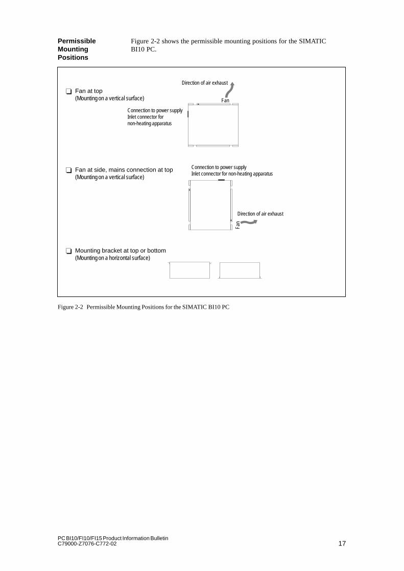
Figure 2-2 shows the permissible mounting positions for the SIMATICBI10 PC.� Fan at top
(Mounting on a vertical surface)
Connection to power supplyInlet connector fornon-heating apparatus
Direction of air exhaust
Fan
Fan
Direction of air exhaust
� Fan at side, mains connection at top(Mounting on a vertical surface)� Mounting bracket at top or bottom(Mounting on a horizontal surface)
Connection to power supplyInlet connector for non-heating apparatus
Figure 2-2 Permissible Mounting Positions for the SIMATIC BI10 PC
PermissibleMountingPositions

18PC BI10/FI10/FI15 Product Information Bulletin
C79000-Z7076-C772-02
The mounting positions for the SIMATIC BI10 PC shown in Figure 2-3 areinadmissible.
Connection to power supplyInlet connector fornon-heating apparatus
Fan
Direction of air exhaust
Fan
Direction of air exhaust
� Fan at bottom
� Fan at side, power supply connection at bottom
Connection to power supplyInlet connector for non-heating apparatus
Figure 2-3 Inadmissible Mounting Positions for the SIMATIC BI10 PC
InadmissibleMountingPositions

19PC BI10/FI10/FI15 Product Information BulletinC79000-Z7076-C772-02
2.2.2 Installing the FI10
Proceed as follows:� Place the device in the prepared panel cutout (see Figure 2-6) and protectit against falling out until it can be permanently secured.� Make sure that the seal is properly attached.� Clamp the device in the panel with the six screw spanners (threadedspindles) provided by hooking a screw spanner onto the front frame of thePC and turning the threaded spindle from the back toward the panel.
335
290
126.5
120
Figure 2-4 Installing the FI10
When tightening the threaded spindles, make sure that� All six spindles are equally tight and� The seal is not completely compressed. A gap of one millimeter should beleft all the way round between the front of the control panel and the rearof the front panel of the FI10.
PanelMounting

20PC BI10/FI10/FI15 Product Information Bulletin
C79000-Z7076-C772-02
Figure 2-5 Rear of the FI10 Front Panel
305+0.5
265
+0.
5
Figure 2-6 Control Panel Cutout for the FI10

21PC BI10/FI10/FI15 Product Information BulletinC79000-Z7076-C772-02
2.2.3 Installing the FI15
The SIMATIC PC FI15 is equipped with four threaded bolts on eachlongitudinal and two on each lateral side (M5 x 11) for installing theindustrial PC directly on a machine.
The drilling template included in the document supplement can be used tosize the panel cutout and drill the holes.
125
121
335
450
127.5
132.5
Figure 2-7 Installing the FI15

22PC BI10/FI10/FI15 Product Information Bulletin
C79000-Z7076-C772-02
2.3 Connecting the I/O Devices
The SIMATIC PC BI10, FI10 and FI15 are designed so that the boxrepresents the core component of all three systems. This means that allinterfaces and connections provided on the BI10 are also provided on theFI10 and FI15 systems. The differences in the three are listed in the tablebelow.
Connections Function BI10 FI10 FI15
VGA VGA port for connecting an external monitor15-pin, sub D socket connector
Yes Yes Yes
COM1 Serial port 1 (V.24/RS232C)25-pin, sub D socket connector
Yes Yes Yes
COM2 Serial port 2 (V.24/RS232C)9-pin, sub D connector
Yes Yes Yes
Mouse PS/2 mouse port Yes Yes Assign.*1
Keyboard PS/2 keyboard port Yes Yes Yes *2
LPT1 Parallel portPort for devices with a parallelport (such as a printer)25-pin, sub D socket connector
Yes Yes Yes
MPI Multipoint interfaceFor connecting an S7 programmable controller9-pin, sub D socket connector
Yes Yes Yes
Inlet connector fornon-heatingapparatus
115/230 VAC power supply Yes Yes Yes
PCMCIA PCMCIA connector with Eject and Lock for 2 x PCMCIACard Type II or 1 x PCMCIA Card Type III
Yes Yes Yes
The use of expansion boards increases the number of interfaces. Please readthe literature accompanying these boards for descriptions of the interfacesprovided by them.
*1: On the FI15, the PS/2 mouse port is reserved for (that is, used by) thestandard built-in finger mouse (touch pad). It is not possible to connect anexternal mouse.
*2: On the FI15, a PS/2 keyboard can be interfaced to thefront panel of the PC.The port is located behind the front cover. The box’s PS/2 keyboard port canbe used only alternatively, not at the same time as the front-panel port.
*3: When using the optional touch screen (see 3.9) you must not use the externalCOM2 interface.
23PC BI10/FI10/FI15 Product Information BulletinC79000-Z7076-C772-02
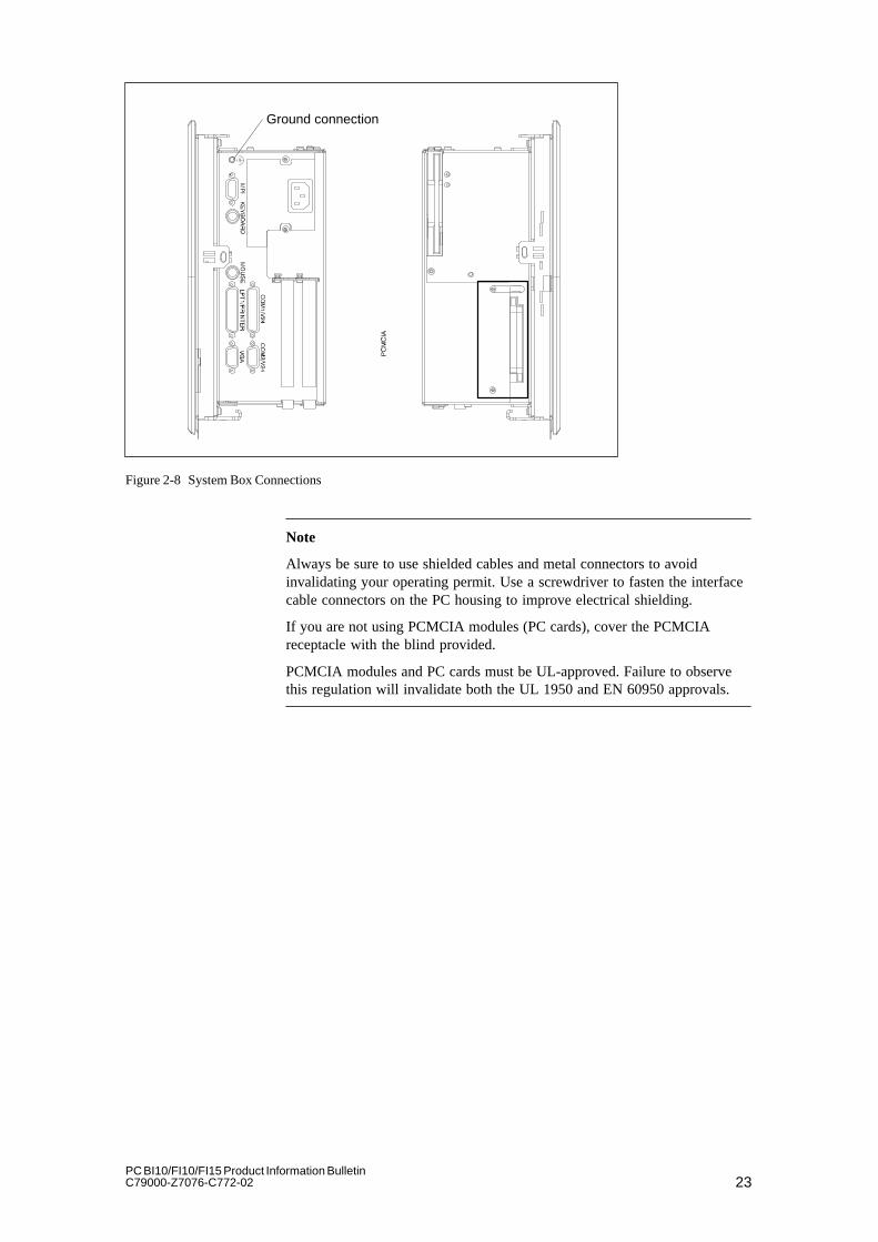
Ground connection
Figure 2-8 System Box Connections
Note
Always be sure to use shielded cables and metal connectors to avoidinvalidating your operating permit. Use a screwdriver to fasten the interfacecable connectors on the PC housing to improve electrical shielding.
If you are not using PCMCIA modules (PC cards), cover the PCMCIAreceptacle with the blind provided.
PCMCIA modules and PC cards must be UL-approved. Failure to observethis regulation will invalidate both the UL 1950 and EN 60950 approvals.
24PC BI10/FI10/FI15 Product Information Bulletin
C79000-Z7076-C772-02
2.4 Connecting the Power Supply
The power supply unit in the SIMATIC BI10, FI10, and FI15 is designed foran a.c. input voltage of 120V/240V + 6% – 10% with input currents of1.4/0.8A for a.c. networks with 50/60 Hz. Because it is a varying voltagepower supply unit, voltage selection is unnecessary.
The SIMATIC BI10, FI10, and FI15 have no on/off switch. To turn one ofthese devices on or off, you must either switch off the mains power or pullthe power plug.
The socket outlet on the device or the grounding contact for the buildingwiring systems must be accessible. The grounding contact for the buildingwiring system must be located as near to the device as possible.
Additional equipotential bonding between PC and environment can beestablished via the grounding terminal on the box.
25PC BI10/FI10/FI15 Product Information BulletinC79000-Z7076-C772-02
Setting Up and Operating the PC
In this chapter, you will learn:� How to start up your PC for the first time, and� How to use the electronic manual.
Chapter Overview
3
26PC BI10/FI10/FI15 Product Information Bulletin
C79000-Z7076-C772-02
3.1 Setting Up and Operating the PC
3.1.1 Operating Elements and Displays
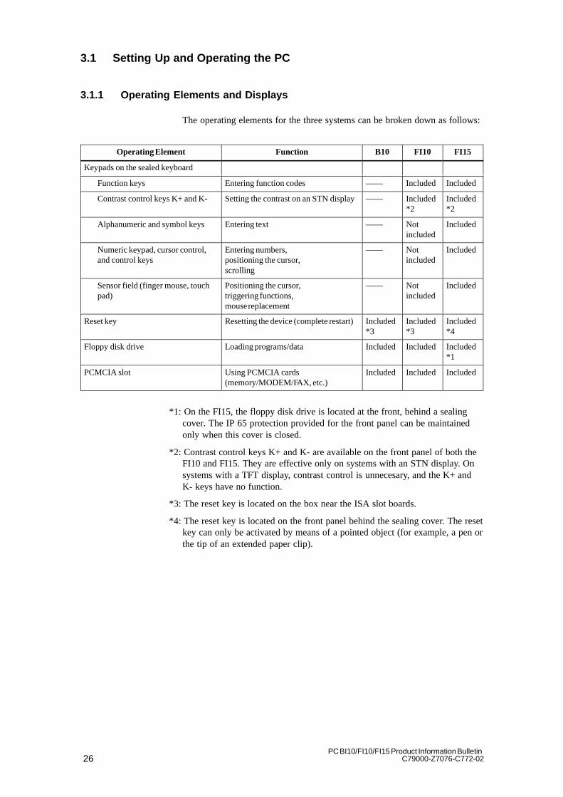
The operating elements for the three systems can be broken down as follows:
Operating Element Function B10 FI10 FI15
Keypads on the sealed keyboard
Function keys Entering function codes –––– Included Included
Contrast control keys K+ and K- Setting the contrast on an STN display–––– Included*2
Included*2
Alphanumeric and symbol keys Entering text –––– Notincluded
Included
Numeric keypad, cursor control,and control keys
Entering numbers,positioning the cursor,scrolling
–––– Notincluded
Included
Sensor field (finger mouse, touchpad)
Positioning the cursor,triggering functions,mouse replacement
–––– Notincluded
Included
Reset key Resetting the device (complete restart)Included*3
Included*3
Included*4
Floppy disk drive Loading programs/data Included Included Included*1
PCMCIA slot Using PCMCIA cards(memory/MODEM/FAX, etc.)
Included Included Included
*1: On the FI15, the floppy disk drive is located at the front, behind a sealingcover. The IP 65 protection provided for the front panel can be maintainedonly when this cover is closed.
*2: Contrast control keys K+ and K- are available on the front panel of both theFI10 and FI15. They are effective only on systems with an STN display. Onsystems with a TFT display, contrast control is unnecesary, and the K+ andK- keys have no function.
*3: The reset key is located on the box near the ISA slot boards.
*4: The reset key is located on the front panel behind the sealing cover. The resetkey can only be activated by means of a pointed object (for example, a pen orthe tip of an extended paper clip).
27PC BI10/FI10/FI15 Product Information BulletinC79000-Z7076-C772-02
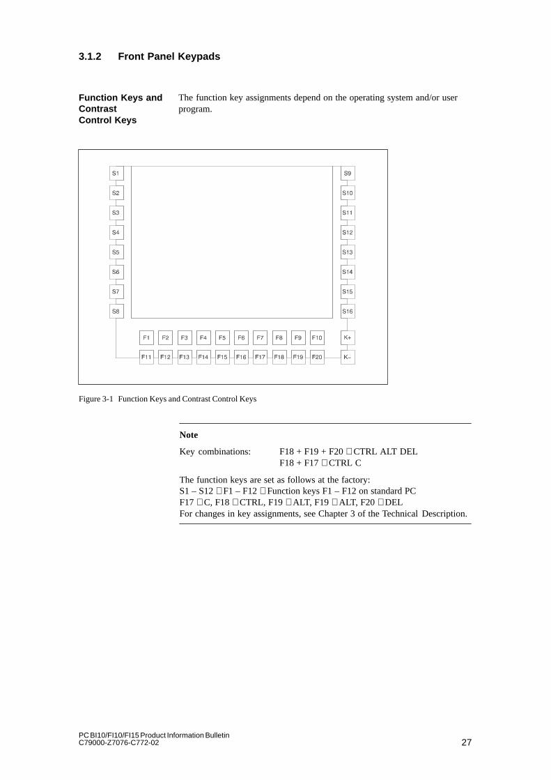
3.1.2 Front Panel Keypads
The function key assignments depend on the operating system and/or userprogram.
Figure 3-1 Function Keys and Contrast Control Keys
Note
Key combinations: F18 + F19 + F20 ≅ CTRL ALT DELF18 + F17 ≅ CTRL C
The function keys are set as follows at the factory:S1 – S12 ≅ F1 – F12 ≅ Function keys F1 – F12 on standard PCF17 ≅ C, F18 ≅ CTRL, F19 ≅ ALT, F19 ≅ ALT, F20 ≅ DELFor changes in key assignments, see Chapter 3 of the Technical Description.
Function Keys andContrast Control Keys

28PC BI10/FI10/FI15 Product Information Bulletin
C79000-Z7076-C772-02
The letters and symbols are arranged alphabetically in a matrix (see 3-2):
Figure 3-2 Alphanumeric / Symbol Keypad
Note
Key combinations: SHIFT + KEY = Symbol
� + KEY = Upper-case letter
In addition to digits, the numeric keypad also contains the spacebar, thedecimal point, the symbols for the four basic arithmetic functions, and thetabulator, backspace and enter keys; the control keys are at the left of thenumeric keypad.
Figure 3-3 Numeric Keypad, Cursor Control Keys, and Control Keys
Alphanumeric /Symbol Keys
Numeric Keypad,Cursor ControlKeys, and ControlKeys

29PC BI10/FI10/FI15 Product Information BulletinC79000-Z7076-C772-02
Key combinations are formed with the CTRL and/or Alt keys, andare entered as follows:� Press and hold the CTRL and/or Alt keys.� Press the key for the required function.
Abort current operationAborts the operation currently in progress, but does not clear the linebuffer.
Warm restartThis key combination restarts your PC.
Note
For additional key combinations, please refer to the documentation providedwith your operating system as well as that for your user program.
You can use the sensor field as though it were a mouse. The mouse pointermakes the same moves on the screen as your finger makes as it moves overthe surface of the sensor field. The two small fields shown in the diagrambelow represent the two mouse buttons.
Sensor field
Figure 3-4 Sensor Field
Important KeyCombinations
Ctrl
Ctrl Alt Del
Sensor Field(Finger Mouse orTouch Pad)

30PC BI10/FI10/FI15 Product Information Bulletin
C79000-Z7076-C772-02
You can click on symbols or texts using the two mouse buttons. First, movethe mouse pointer to the symbol you want, then press the left mouse button toselect that symbol.
Alternatively, when using a full-graphics operator interface, such asWindows, you can click on a symbol and move the mouse pointer to thatsymbol. Then briefly press the sensor field with your finger twice insuccession to open the symbol.
You need not put pressure on the sensor field surface. The sensor does notrespond to the pressure of your finger, but rather to the change in capacitanceat the point of contact.
3.1.3 Floppy Disk Drive
Floppy disk drives are equipped with an access slot for the diskettes; this slotis covered by a flap. When a floppy disk is inserted incorrectly, it will not fitin the slot. A disk can be ejected by pushing the eject button on the drive.
The eject button must never be pressed while the green LED on the drive ison. Caution: This could result in loss of data.
3.1.4 PCMCIA Slot
A maximum of two Type II or one Type III PCMCIA cards can be inserted inthe PCMCIA slot. The slot has two ejectors for removing inserted cards.
3.1.5 Reset Key
If your PC is equipped with a reset key, a hardware reset is triggered whenyou press this key. The PC is restarted.
On the FI15, the reset key is integrated in the front panel under the covernext to the floppy disk drive. The reset key can only be activated with apointed object (for example, a pen or the tip of an extended paper clip).
On the FI10 and BI10, the reset key is situtated on the box near the slotboards. You can activate the reset key by hand, without using any additionaltool.
3.1.6 CD-ROM Drive
An external CD-ROM drive can be connected to the LPT interface of the PC.Details on the type of drive can be obtained from the SIMATIC PC Hotline(see Chapter 5).

31PC BI10/FI10/FI15 Product Information BulletinC79000-Z7076-C772-02
3.1.7 Display
The FI10 and FI15 are equipped with 10.4” LCD displays. These displays areprecabled and preset at the factory. VGA monitors can be operated in parallelto these displays. The specification as to whether to operate only a display ora VGA monitor in parallel is made in BIOS Setup.
3.1.8 LEDs
At the bottom left on the FI10 and at the left center on the FI15 you will findthree light-emitting diodes. The Power LED is a single LED (green), theRUN and TEMP LEDs are dual LEDs (red/green). RUN and TEMP arecontrolled by the SafeCard (optional).
Designation Color Description
RUN Red/green
Off: No SafeCard or watchdog timer started or no power
Green:Watchdog timer started or not expired
Red: Watchdog timeout
TEMP Red/green
Off: No SafeCard or no power
Green:Temperature within admissiblerange
Red: Temperature out of rangeorno temperature sensor connected orcable to temperature sensor interrupted.
POWER Green Off: No powerOn: Power on
32PC BI10/FI10/FI15 Product Information Bulletin
C79000-Z7076-C772-02
3.2 Starting Up Your PC for the First Time
Once the I/Os and the system unit have been connected, your PC is ready tobe put into operation.
Plug your PC into the mains power supply.
Disconnect your PC from the mains supply.
Note
The SIMATIC BI10/FI10/FI15 has no ON/OFF switch. In order todisconnect the PC from the power supply, you must pull the plug (see alsoSection 2.4).
When the PC is on, the POWER LED green light is lit (except on the BI10).
3.3 Setting Up Your PC
Your PC’s operating system and system software were preinstalled on thehard disk at the factory. You will have either the English version ofMS-DOS 6.22 or the multi-language version of Windows 95.
When powering up the PC, you must distinguish between the following:� Cold start (also called an initial start)� Complete restart
Your PC software is set up during a cold start. Proceed as follows:
1. Switch on your PC.
2. Set the monitor’s brightness control to the brightest setting (refer to themonitor ’s operating instructions) and switch on the monitor (applies toexternal monitor only).
The PC executes a self-test. The following message appears on the screenduring the self-test:
Press <F2> to enter SETUP
3. Wait until the message disappears, then follow the instructions displayedon the screen.
Your operating system is loaded upon completion of the self-test. Theload procedure itself depends on the operating system (see Sections 3.4and 3.5).
Once it has been set up, the DOS prompt or operator interface of theoperating system you are using is displayed following system startup everytime you switch on or reset the PC.
Switching ON
Switching OFF
Overview
Cold Start
Complete Restart
33PC BI10/FI10/FI15 Product Information BulletinC79000-Z7076-C772-02
3.4 Electronic Manual
Your PC features an online manual. The manual consists of two parts:
– The Product Information Bulletin (the part you are now reading) infive languages (German, English, French, Italian and Spanish) and
– The Technical Description in two languages (German and English).
The User’s Guide is in the following directory:
c:\docu in file U_MAN [D, E, F, I, S].PDF
D = Deutsch (German), E = English, F = French, I = Italian, S = Spanish
The Technical Description is in the following directory:
c:\docu in file T_DES [D, E].PDF
You need the ADOBE Acrobat Reader to print out the User’s Guide and theTechnical Description. The ADOBE Acrobat Reader software is located indirectory
c:\acrodos or c:\acroread
Due to license agreements, the software is not preinstalled and the user mustinstall it himself.
Overview
User’s Guide
TechnicalDescription
ADOBE AcrobatReader
34PC BI10/FI10/FI15 Product Information Bulletin
C79000-Z7076-C772-02
3.5 Installing the ADOBE Acrobat Reader
We recommend that you connect a mouse and install a mouse driver beforeinstalling the ADOBE Acrobat Reader software. Although it is possible touse a keyboard, using a mouse to operate the Acrobat Reader is considerablyeasier.
Proceed as follows to install the ADOBE Acrobat Reader:
1. Start by entering the following:� Install.exe in directory c:\acrodos (MS-DOS 6.22) or� acroread.exe in directory c:\acroread (Windows 95).
The following message is displayed:Adobe Acrobat Reader for DOS Installation, versionx.y orAdobe Acrobat Reader for WINDOWS Installation,version x.y
2. Confirm by pressing any key.
A license agreement is displayed:Adobe Systems Incorporated License Agreement
3. Acknowledge with Accept .
4. You are prompted to enter your name.Press ENTER.
5. Your are prompted to enter your company/department.Press ENTER.
6. You are prompted to enter the directory for the installation. Use thesuggested directory.Press ENTER.
Under Windows 95, the installation from this point on is automatic, and endswith the appearance of the Acrobat Reader icon in a window.
Installing theADOBE AcrobatReader
35PC BI10/FI10/FI15 Product Information BulletinC79000-Z7076-C772-02
Additional steps are required for MS-DOS:
1. You are prompted to select a directory for print fonts. Accept thesuggested directory by simply pressing ENTER.
2. You are asked whether you want to install the Reader Tour, a tutorialwhich requires approximately 0.5 Mbytes on the hard disk. Make yourchoice and press ENTER.
3. You are prompted to specify your working directory (temporarydirectory). Confirm the suggested directory by pressing ENTER.
4. You are prompted to specify a directory for the Swap-out File.Accept the suggested directory by pressing ENTER.
5. You are asked whether you want the installation program to make changesin the CONFIG.SYS and AUTOEXEC.BAT files or whether you want tomake them yourself. We recommend that you accept the suggestedoption, i.e.Go ahead and modifyand confirm it by pressing ENTER.
6. If you failed to connect a mouse or install a mouse driver, an appropriatemessage to this effect is displayed on the monitor. You can install themouse and/or mouse driver after the ADOBE Reader installation has beencompleted. Press ENTER.
7. If the installation was successful, you are prompted to reboot your PC.Acknowledge by pressing ENTER. Reboot your PC (CTRL-ALT-DEL orReset key).
Additional Stepsfor MS-DOS
36PC BI10/FI10/FI15 Product Information Bulletin
C79000-Z7076-C772-02
3.6 Using Adobe Acrobat
Proceed as follows to use the Acrobat Reader:
1. Start the Acrobat Reader by typing in acrobat (MS-DOS 6.22) or clickingon the Acrobat Reader icon under Windows 95. You can start the AcrobatReader from any directory if you followed the recommendations givenduring installation.
An operator interface similar to the MS-DOS Shell appears. Use the TABkey or the mouse to change from window to window. Use the keyboard’scursor control keys (or the mouse) to move the cursor within a givenwindow (remember, your selection has not been made until the line isdisplayed in reverse video; that is, white characters on a blackbackground).
2. Open the file you want to read
U_MAN[D,E,F,I,S].PDF Product Information BulletinT_DES[D,E].PDF Technical Description
D = Deutsch (German), E = English, F = French, I = Italian, S = Spanish
These files are in the c:\docu directory.
3. Use the FILE menu to print out the opened file. First choose PRINTERSETUP from the FILE menu and choose your printer from the list ofprinters. Then choose PRINT from the FILE menu to print out the file.
Working with theAcrobat Reader
37PC BI10/FI10/FI15 Product Information BulletinC79000-Z7076-C772-02
3.7 SafeCard
Please take information on the SafeCard module from the TechnicalDescription. To install the SafeCard driver for different operating systems,see the ReadMe.TXT file in the C:\SAFECARD directory.
3.8 Direct Key Submodule
Notes on installing and operating the the direct key submodule can be foundin the Technical Description.The direct key submodule cannot be used in the BI10.
3.9 Touch Screen Display
For notes on installing and operating the touch screen display, please refer tothe Technical Description. To install the drivers for the touch screen, changeto directory C: \Touch. The ReadMe.TXT files for the various operatingsystems can be found in the DOS, Win311, Win95, WinNT and OS2subdirectories.
Note
You must not use the COM2 port of the box with device versions which havea touch screen display.
38PC BI10/FI10/FI15 Product Information Bulletin
C79000-Z7076-C772-02
3.10 Saving Hard Disk Data on Floppy Disk
Your industrial PC is delivered with a hard disk containing important dataand programs (such as the operating system) which you must copy todiskette, as these data could be lost in the event of an operator error or harddisk defect.
Your industrial PC is delivered with a Batch routine which greatly simplifiesdata backup during the initial installation. The saving of hard disk data ismenu-driven:� Follow the instructions given by the backup program. To back up the hard
disk data, you will need a number of formatted, empty diskettes (at least16).
During the initial installation of the operating system, you are prompted tomake backup copies. To do so, you will need 40 formatted, empty diskettes(1.44 Mbytes).
Refer to Section 4.7 for instructions on setting up your PC once again.
3.11 Protective Functions
Use passwords in Setup to prevent unauthorized persons from changingentries in Setup. For further information on Setup passwords, refer to Chapter2, Mother Board in the Technical Description (see Section 2.10.3, theSecurity Menu).
Overview
Saving underMS-DOS 6.22
Saving underWindows 95
39PC BI10/FI10/FI15 Product Information BulletinC79000-Z7076-C772-02
Error Diagnostics
In this chapter you will find information on how to localize and troubleshootfrequently recurring problems.� For error messages from the operating system, please refer to your
operating system documentation.� For messages about errors caused by the processor module, refer to thechapter entitled “CPU Module” in the Technical Description. Errormessages output during the self-test (tone sequences, screen messages)are listed in this manual in Sections 4.8 and 4.9.
Note
If you want to connect or disconnect cables, please observe the safetyinstructions given in Chapters 1 and 2.
Chapter Overview
4

40PC BI10/FI10/FI15 Product Information Bulletin
C79000-Z7076-C772-02
4.1 No Response from the PC
Although switched on, the PC shows no reaction whatsoever: the Power LEDdoes not light up.
Problem with power supply.
Proceed as follows:� Check to make sure that the power supply cable is plugged in.� Make sure that the plug is properly inserted in the socket.
Note
If the Power LED still does not light up after taking the corrective measuressuggested above, contact your technical customer service (Chapter 5).
ErrorManifestation
Cause
Remedy
41PC BI10/FI10/FI15 Product Information BulletinC79000-Z7076-C772-02
4.2 Problems When Using Non-Siemens Modules
The PC crashes during startup.
The following causes are possible:
– Multiple assignments of input/output addresses
– Multiple assignments of hardware interrupts and/or DMA channels
– Signal frequencies or signal levels are not maintained
– Deviations in connector pin assignments
Use the Logbook (located inside the PC) to check your computerconfiguration:� If the current configuration is the same as the original configuration,
please contact your technical customer service (Chapter 5).� If the configuration has been modified, restore the original configurationby removing any non-Siemens modules and restarting the PC:
– If the PC still crashes, contact your technical customer service.
– If the problem no longer occurs, the non-Siemens module(s) was/wereprobably the cause. Replace these with Siemens modules or contactthe module supplier.
ErrorManifestation
Cause
Remedy

42PC BI10/FI10/FI15 Product Information Bulletin
C79000-Z7076-C772-02
4.3 The External Monitor Remains Dark
The following causes are possible:
The monitor has been switched off� Switch on the monitor.
The monitor has been blanked� Press any key on the keyboard.
The brightness control has been turned to the darkest setting� Set the brightness control to “bright.” For detailed information, refer tothe instruction manual for your monitor.
The power supply cable or monitor cable is not connected� Switch off the monitor and the system unit.� Check to make sure that the power supply cable is properly connected tothe monitor and the system unit and is plugged properly into the mainsoutlet.� Check to make sure that the monitor cable is correctly connected to thesystem unit and the monitor (if there is a plug-in connector).� Switch on the monitor and the system unit.
Incorrect monitor settings specified in SETUP� Press and hold the INSERT key during booting. This forcesSIMULTANEOUS mode. Afterwards, in SETUP (function key F2 inresponse to the prompt), set the correct mode under menu item “HWOptions,” CRT/LCD Parameter Selection.
Note
If the monitor still remains dark after taking all of the corrective measuresrecommended above, contact your technical customer service (Chapter 5).
Cause/Remedy
43PC BI10/FI10/FI15 Product Information BulletinC79000-Z7076-C772-02
4.4 No Display or Drifting Display on External Monitor
The wrong line frequency and/or the wrong resolution has been set for themonitor or the user program.� Terminate the user program. If the error still occurs, switch off the
monitor and wait at least three seconds before switching it on again.� Make the proper entries for your monitor in the CONFIG.SYS file (on thehard disk).� Correct the settings for monitor and graphics in your user program.� Select the right screen driver for your user program.
4.5 No Mouse Pointer on Monitor or Display
The mouse pointer may fail to appear for one of the following reasons:
Mouse driver not loaded� Check to make sure that the mouse driver has been properly installed, andthat it is available when the user program is started. For detailedinformation on the mouse driver, please refer to the mouse manual orapplication manual.
Mouse not connected� Terminate your user program and exit the operating system.� Switch off your PC by removing the power supply plug.� Check to make sure that the mouse cable is properly connected to thesystem unit. If you are using an adapter or extension cord for the mousecable, check that connection as well.� Switch on the PC by removing the power supply plug.
Note
If the mouse pointer still does not appear after you have taken all of thecorrective measures listed above, contact your technical customer service(Chapter 5).
4.6 PC Shows Incorrect Time and/or Date
Set the time or date in the Setup menu.
Press <F2> to invoke Setup while booting your PC.
Note
If the time and/or date are still incorrect after you have switched the PC offand on again, the battery is low or fully discharged. In this case, contact yourtechnical customer service (Chapter 5).
Cause/Remedy
Cause/Remedy
Remedy
44PC BI10/FI10/FI15 Product Information Bulletin
C79000-Z7076-C772-02
4.7 Restoring the Hard Disk (Data Erased)
If you have a system disk and a backup copy of the hard disk, you can restoreyour hard disk. This process restores the directories and files that were on thehard disk at the time the backup copy was made.
1. Start the PC with the system disk inserted.
2. Partition the hard disk with the MS-DOS FDISK command(this requires thorough knowledge of the system).
3. Format the hard disk with the MS-DOS FORMAT command and the /soption (for example, FORMAT C: /s ). The /s option is used to copy tothe hard disk those system files needed to start the operating system.
Restore your files on the hard disk. To do so, use MS-DOS’s XCOPYcommand and the backup diskettes you made as described in Section 3.10.Insert the first backup diskette.
1. The command
A: <CR>XCOPY *.* C:\ /s<CR>
copies the data back to the hard disk.
2. When the first diskette has been copied, insert the next diskette, repeatingthis step until all diskettes have been copied. You have now restored thehard disk to its original state.
3. If your hard disk still does not work properly after it has been restored, itmust be replaced.
Follow the instructions given in the section entitled Installing Windows 95 inthe User’s Guide entitled Introduction to Microsoft Windows 95. Someadditional information is listed below:
Starting the SETUP program for Windows 95
1. Start SETUP.EXE.
2. Confirm the start message by pressing Enter.
3. After it has checked your drives, exit SCANDISK by pressing Exit .
4. The Welcome screen for the Setup program is displayed. Acknowledgewith Next. Setup executes several routine PC checks and readies theSetup Assistant.
5. When you are prompted to do so, insert further diskettes and confirm withOK .
License Agreement for Windows 95
6. Read the MICROSOFT WINDOWS 95 END USER LICENSEAGREEMENT carefully and agree to its conditions with Yes.
Cause/Remedy
UnderMS-DOS 6.22
Under Windows 95
45PC BI10/FI10/FI15 Product Information BulletinC79000-Z7076-C772-02
Windows 95 Setup Assistant
7. Then you see Request system information, which you start by selectingNext. You must first choose a directory. Select C:\Windows and confirmwith Next.
8. The standard setup mode is suggested. Confirm with Next.
Hardware Identification
9. Make sure that all devices and modules have been properly connected orinstalled, and activate the check boxes of any additional components.Confirm with Next. This procedure can take several minutes.
Communication without Limits
10. Activate the checkboxes for the communications programs you want toinstall. Confirm your selection with Next.
Windows Components
11. As recommended, select Install standard components, confirming yourselection with Next.
Create Start Diskette
12. Respond to the Create start diskette prompt with No and confirm withNext.
Start Copying the Windows 95 Files
13. Confirm Copy Windows 95 files with Next. The Windows files are thencopied to the hard disk.
System Restart
14. When the files have been copied, preparations are made for the restart.Confirm Restart the system and terminate installation with Next. Thesystem restart then begins.
Preparations are made for the initial startup of Windows 95, and theconfiguration files are updated. The system control is generated, theprograms entered in the Start menu, Windows Help is prepared, and MS-DOSprograms are configured.
Time Zone
15. Now you can select the time zone of the area in which you live bychoosing your country with the mouse. Confirm your selection withClose.
This completes the Windows 95 installation.
46PC BI10/FI10/FI15 Product Information Bulletin
C79000-Z7076-C772-02
4.8 An Error Message Appears on the Monitor or Display
The error messages output by the BIOS system are listed below. For a list oferror messages output by the operating system or the various programs,please refer to the respective manuals.
Press <F2> during booting to invoke Setup.
On-Screen Error Message Description / Suggestions
Address conflict Plug & Play problemContact your technical customer service.
Combination not supported Plug & Play problemContact your technical customer service.
IO device IRQ conflict Plug & Play problemContact your technical customer service.
Invalid System Configuration DataPlug & Play problemPlease set the RESET CONFIGURATION DATA option in Setup’s Advancedmenu.Contact your technical customer service.
Allocation Error for Plug & Play problemPlease undo the last hardware modification.Contact your technical customer service.
System battery is deadReplace and run SETUP
Battery on the CPU module is defective or discharged.Contact your technical customer service.
System CMOS checksum badrun SETUP
Call SETUP, make the necessary entries, and save them. If this message alwaysappears on runup, contact your technical customer service.
Incorrect Drive A typerun SETUP
Check the SETUP entries for drive A.
Incorrect Drive B typerun SETUP
Check the SETUP entries for drive B.
Diskette drive A error Error while accessing drive A.Contact your technical customer service.
Diskette drive B error Fundamental error.Contact your technical customer service.
Failure Fixed Disk Error while accessing the hard disk.Check the SETUP entries.Contact your technical customer service.
Keyboard error Check to make sure that the keyboard is properly connected.
Stuck Key Check the keyboard to see if a key is stuck.
K System RAM Failed at offset: Memory error.Contact your technical customer service.
K Shadow RAM Failed at offset: Memory error.Contact your technical customer service.
K Extended RAM Failed at offset: Memory error.Contact your technical customer service.
Failing Bits: Memory error.Contact your technical customer service.
Error Messages

47PC BI10/FI10/FI15 Product Information BulletinC79000-Z7076-C772-02
On-Screen Error Message Description / Suggestions
Operating system not found Possible causes:No operating system.Wrong drive addressed (diskette in drive A/B).Wrong active boot partition.Incorrect drive entries in SETUP.
Previous boot incompleteDefault configuration used
Previous boot was aborted, for example due to power failure. Correct theSETUP entries.
System cache errorCache disabled
Cache error on the CPU module.Contact your technical customer service.
Monitor type does not matchCMOSRun SETUP
Monitor conflicts with SETUP entries.Make proper SETUP entries for the monitor you are using.
System timer error Hardware fault.Contact your technical customer service.
Real time clock error Clock chip error.Contact your technical customer service.
Keyboard controller error Keyboard error.Contact your technical customer service.
48PC BI10/FI10/FI15 Product Information Bulletin
C79000-Z7076-C772-02
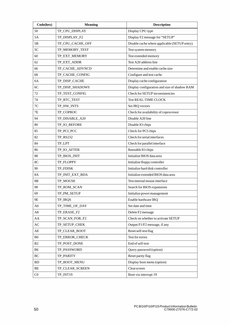
4.9 Error Messages from the Self-Test (POST Codes)
At the start of the system startup, the hardware executes a self-test called aPOST (Power On Self Test). The individual steps executed during theself-test are output to I/O port 80h. Errors can be diagnosed via the associatedtone sequence (codes 01 to 4A).
Always contact your customer service representative and tell him the tonesequence if necessary.
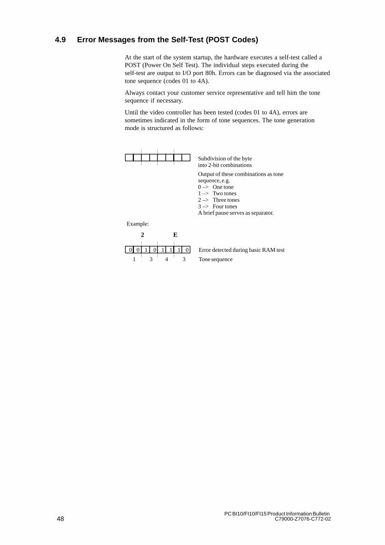
Until the video controller has been tested (codes 01 to 4A), errors aresometimes indicated in the form of tone sequences. The tone generationmode is structured as follows:
Subdivision of the byte into 2-bit combinations
Output of these combinations as tonesequence, e.g.0 –> One tone1 –> Two tones2 –> Three tones3 –> Four tonesA brief pause serves as separator.
Example:
2 E
0 0 0 01111 Error detected during basic RAM test
1 3 4 3 Tone sequence

49PC BI10/FI10/FI15 Product Information BulletinC79000-Z7076-C772-02
The POST codes in the order of their occurrence:
Code(hex) Meaning Description
02 TP_VERIFY_REAL Test to see if CPU is in Real mode
04 TP_GET_CPU_TYPE Determine CPU type
06 TP_HW_INIT Initialize basic hardware (DMA, IRQ)
18 TP_TIMER_INIT Initialize timers
08 TP_CS_INIT Initialize chipset
0C TP_CACHE_INIT Initialize cache
16 TP_CHECKSUM EPROM checksum test
28 TP_SIZE_RAM Determine RAM capacity
3A TP_CACHE_AUTO Determine cache size
2A TP_ZERO_BASE Set 512K base RAM to 0
2C TP_ADDR_TEST Test base RAM address lines
2E TP_BASERAML Test 1.64K base RAM
38 TP_SYS_SHADOW BIOS shadow
20 TP_REFRESH Refresh chip test
09 TP_SET_IN_POST Start Power On Self-Test
0A TP_CPU_INIT Initialize CPU
0B TP_CPU_CACHE_ON Switch on cache
0F TP_FDISK_INIT Initialize hard disk
14 TP_8742_INIT Initialize 8742 chip
1A TP_DMA_INIT Initialize DMA chips
1C TP_RESET_PIC Reset interrupt controller
22 TP_8742_TEST Test 8742 chip
32 TP_COMPUTE_SPEED Determine clock pulse
34 TP_CMOS_TEST Test CMOS RAM
C1 TP_7xx_INIT Initialize PG 7xx I/Os
3C TP_ADV_CS_CONFIG Configure advanced chipset
42 TP_VECTOR_INIT Initialize interrupt vectors
46 TP_COPYRIGHT Check copyright
47 TP_PCI_OP_INIT Initialize the PCI interface
49 TP_PCI_INIT Initialize PCI interface
48 TP_CONFIG Check configuration
4A TP_VIDEO Initialize video interface
4C TP_VID_SHADOW Copy video BIOS to RAM
52 TP_KB_TEST Keyboard available?
54 TP_KEY_CLICK Switch keyboard click on/off
76 TP_KEYBOARD Test keyboard
58 TP_HOT_INT Test for unexpected interrupts
4B TP_QUIETBOOT_START Disable boot messages, if any
4E TP_CR_DISPLAY Display copyright notice
50PC BI10/FI10/FI15 Product Information Bulletin
C79000-Z7076-C772-02
Code(hex) DescriptionMeaning
50 TP_CPU_DISPLAY Display CPU type
5A TP_DISPLAY_F2 Display F2 message for “SETUP”
5B TP_CPU_CACHE_OFF Disable cache where applicable (SETUP entry)
5C TP_MEMORY_TEST Test system memory
60 TP_EXT_MEMORY Test extended memory
62 TP_EXT_ADDR Test A20 address line
66 TP_CACHE_ADVNCD Determine and enable cache size
68 TP_CACHE_CONFIG Configure and test cache
6A TP_DISP_CACHE Display cache configuration
6C TP_DISP_SHADOWS Display configuration and size of shadow RAM
72 TP_TEST_CONFIG Check for SETUP inconsistencies
74 TP_RTC_TEST Test REAL-TIME CLOCK
7C TP_HW_INTS Set IRQ vectors
7E TP_COPROC Check for availability of coprocessor
94 TP_DISABLE_A20 Disable A20 line
80 TP_IO_BEFORE Disable IO chips
85 TP_PCI_PCC Check for PCI chips
82 TP_RS232 Check for serial interfaces
84 TP_LPT Check for parallel interface
86 TP_IO_AFTER Reenable IO chips
88 TP_BIOS_INIT Initialize BIOS data area
8C TP_FLOPPY Initialize floppy controller
90 TP_FDISK Initialize hard disk controller
8A TP_INIT_EXT_BDA Initialize extended BIOS data area
8B TP_MOUSE Test internal mouse interface
98 TP_ROM_SCAN Search for BIOS expansions
69 TP_PM_SETUP Initialize power management
9E TP_IRQS Enable hardware IRQ
A0 TP_TIME_OF_DAY Set date and time
A8 TP_ERASE_F2 Delete F2 message
AA TP_SCAN_FOR_F2 Check on whether to activate SETUP
AC TP_SETUP_CHEK Output F1/F2 message, if any
AE TP_CLEAR_BOOT Reset self-test flag
B0 TP_ERROR_CHECK Test for errors
B2 TP_POST_DONE End of self-test
B6 TP_PASSWORD Query password (option)
BC TP_PARITY Reset parity flag
BD TP_BOOT_MENU Display boot menu (option)
BE TP_CLEAR_SCREEN Clear screen
C0 TP_INT19 Boot via interrupt 19
51PC BI10/FI10/FI15 Product Information BulletinC79000-Z7076-C772-02
Service for SIMATIC PCs
For all your service needs, contact your regional service department or repaircenter (service shop). You can obtain the addresses from the SIMATICCustomer Support Hotline.
Chapter Overview
5
52PC BI10/FI10/FI15 Product Information Bulletin
C79000-Z7076-C772-02
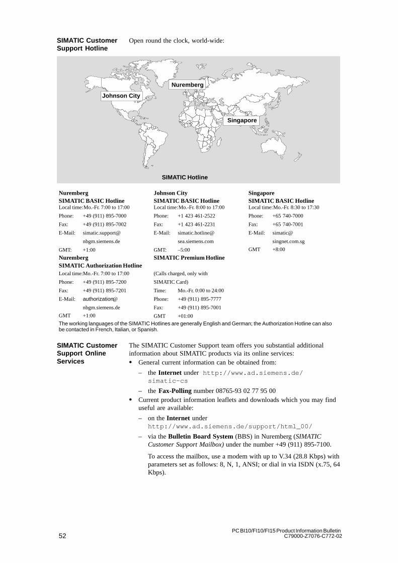
Open round the clock, world-wide:
Johnson City
Nuremberg
Singapore
SIMATIC Hotline
NurembergSIMATIC BASIC Hotline
Johnson CitySIMATIC BASIC Hotline
SingaporeSIMATIC BASIC Hotline
Local time:Mo.-Fr. 7:00 to 17:00
Phone: +49 (911) 895-7000
Fax: +49 (911) 895-7002
E-Mail: simatic.support@
nbgm.siemens.de
GMT: +1:00
Local time:Mo.-Fr. 8:00 to 17:00
Phone: +1 423 461-2522
Fax: +1 423 461-2231
E-Mail: simatic.hotline@
sea.siemens.com
GMT: –5:00
Local time:Mo.-Fr. 8:30 to 17:30
Phone: +65 740-7000
Fax: +65 740-7001
E-Mail: simatic@
singnet.com.sg
GMT +8:00
NurembergSIMATIC Authorization Hotline
SIMATIC Premium Hotline
Local time:Mo.-Fr. 7:00 to 17:00
Phone: +49 (911) 895-7200
Fax: +49 (911) 895-7201
E-Mail: authorization@
nbgm.siemens.de
GMT +1:00
(Calls charged, only with
SIMATIC Card)
Time: Mo.-Fr. 0:00 to 24:00
Phone: +49 (911) 895-7777
Fax: +49 (911) 895-7001
GMT +01:00
The working languages of the SIMATIC Hotlines are generally English and German; the Authorization Hotline can alsobe contacted in French, Italian, or Spanish.
The SIMATIC Customer Support team offers you substantial additionalinformation about SIMATIC products via its online services:� General current information can be obtained from:
– the Internet under http://www.ad.siemens.de/simatic-cs
– the Fax-Polling number 08765-93 02 77 95 00� Current product information leaflets and downloads which you may finduseful are available:
– on the Internet underhttp://www.ad.siemens.de/support/html_00/
– via the Bulletin Board System (BBS) in Nuremberg (SIMATICCustomer Support Mailbox) under the number +49 (911) 895-7100.
To access the mailbox, use a modem with up to V.34 (28.8 Kbps) withparameters set as follows: 8, N, 1, ANSI; or dial in via ISDN (x.75, 64Kbps).
SIMATIC CustomerSupport Hotline
SIMATIC CustomerSupport OnlineServices
53PC BI10/FI10/FI15 Product Information BulletinC79000-Z7076-C772-02
5.1 Regional Repair Centers
Region Phone Fax
Augsburg +49 (821)2595 599 +49 (821)2595 546
Berlin +49 (30)386 34926 +49 (30)386 34933
Bielefeld +49 (521)291 323 +49 (521)291 538
Bremen +49 (421)364 2093 +49 (421)364 2107
Chemnitz +49 (371)475 3860 +49 (371)475 3888
Cologne Ossendorf +49 (221)576 6633 +49 (221)576 6630
Erlangen +49 (9131)7 31048 +49 (9131)7 35263
Essen +49 (201)816 1580 +49 (201)816 1522
Frankfurt +49 (69)797 7358 +49 (69)797 7131
Hamburg +49 (40)2889 4230 +49 (40)2889 4430
Hanover Laatzen +49 (511)877 2241 +49 (511)877 1320
Karlsruhe +49 (721)595 4183 +49 (721)595 6667
Langen +49 (69)797 5608 +49 (69)797 5567
Leipzig +49 (341)210 2049 +49 (341)210 2049
Mannheim +49 (621)456 1328 +49 (621)456 1460
Munich +49 (89)9221 6213 +49 (89)9221 6201
Nuremberg +49 (911)654 6127 +49 (911)654 7630
Saarbrücken +49 (681)386 2598 +49 (681)386 2397
Stuttgart Weilimdorf +49 (711)137 6001 +49 (711)137 6210
54PC BI10/FI10/FI15 Product Information Bulletin
C79000-Z7076-C772-02
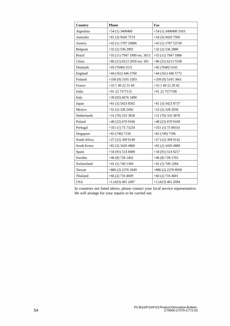
Country Phone Fax
Argentina +54 (1) 3408400 +54 (1) 3408400 3163
Australia +61 (3) 9420 7274 +54 (3) 9420 7500
Austria +43 (1) 1707 29886 +43 (1) 1707 53730
Belgium +32 (2) 536 2905 +32 (2) 536 2880
Brazil +55 (11) 7947 1999 ext. 3013+55 (11) 7947 1888
China +86 (21) 6213 2050 ext. 301 +86 (21) 6213 5538
Denmark +45 (7640) 5151 +45 (7640) 5143
England +44 (161) 446 5760 +44 (161) 446 5772
Finland +358 (9) 5105 3303 +358 (9) 5105 3661
France +33 1 49 22 31 60 +33 1 49 22 29 42
India +91 22 7577115 +91 22 7577106
Italy +39 (02) 6676 3490
Japan +81 (3) 5423 8502 +81 (3) 5423 8737
Mexico +52 (5) 328 2456 +52 (5) 328 2058
Netherlands +31 (70) 333 3858 +31 (70) 333 3878
Poland +48 (22) 670 9166 +48 (22) 670 9169
Portugal +351 (1) 75 73234 +351 (1) 75 89333
Singapore +65 (740) 7150 +65 (740) 7196
South Africa +27 (12) 309 0149 +27 (12) 309 0142
South Korea +82 (2) 3420 4880 +82 (2) 3420 4889
Spain +34 (91) 514 8400 +34 (91) 514 9217
Sweden +46 (8) 728 1462 +46 (8) 728 1703
Switzerland +41 (1) 749 1304 +41 (1) 749 1284
Taiwan +886 (2) 2376 1849 +886 (2) 2378 8958
Thailand +66 (2) 716 4609 +66 (2) 716 4601
USA +1 (423) 461 2497 +1 (423) 461 2094
In countries not listed above, please contact your local service representative.He will arrange for your repairs to be carried out.


Siemens Aktiengesellschaft
E Siemens AG 1998
C79000-Z7076-C772Printed in the Federal Republic of Germany
Siemens AGBereich Automatisierungs- und AntriebstechnikGeschaeftsgebiet Industrie-AutomatisierungssystemePostfach 4848, D-90327 Nuernberg Subject to change without prior notice.


![La noción de policía en los trabajos de Michel Foucault: …Robeo * fi15. 06 3. 7, 8x5. - ifa. 7rc9 * f22v rc7r-7046 (f Thftfl21) - 7746-460ff (flv 5svflh) [189] Ro bertBb uf ieRtrno](https://img.pdfslide.us/doc/110x75/60ab53e0093e9902d0388905/la-nocin-de-polica-en-los-trabajos-de-michel-foucault-robeo-fi15-06-3-7.jpg)