Embed Size (px)
Citation preview
SIMATIC NET Industrial Wireless LAN Netzwerkmanagement White Paper • 2003
SIMATIC NET White Paper Wireless LAN April 2003
Copyright © Siemens AG 2000 All Rights reserved Page 2 of 72 E x c e lle n c e in
A u to m a tio n &Driv e s :S ie m e n s
Objective: The purpose of this White Paper is to: ��explain wireless LAN technology ��explain other wireless technology in the wireless LAN field ��provide information on the subject of wireless LAN technology in automation
engineering The White Paper is divided into self-contained chapters that each deal with a specific question. This allows users to gain a quick overview and find answers to their questions without having to read the entire document. The information in this White Paper is valid from: Spring 2003 Published by SIEMENS AG Automation & Drives Group SIMATIC NET Industrial Communication P.O. Box 4848 90327 Nuremberg Additional support: Should you have additional questions, please get in touch with the Siemens contact at your local branch office or agency. You will also find Simatic Net on the Internet at
http://www.siemens.com/simatic-net
This symbol identifies references to Simatic Net products or special Simatic Net solutions
SIMATIC NET White Paper Wireless LAN April 2003
Copyright © Siemens AG 2000 All Rights reserved Page 3 of 72 E x c e lle n c e in
A u to m a tio n &Driv e s :S ie m e n s
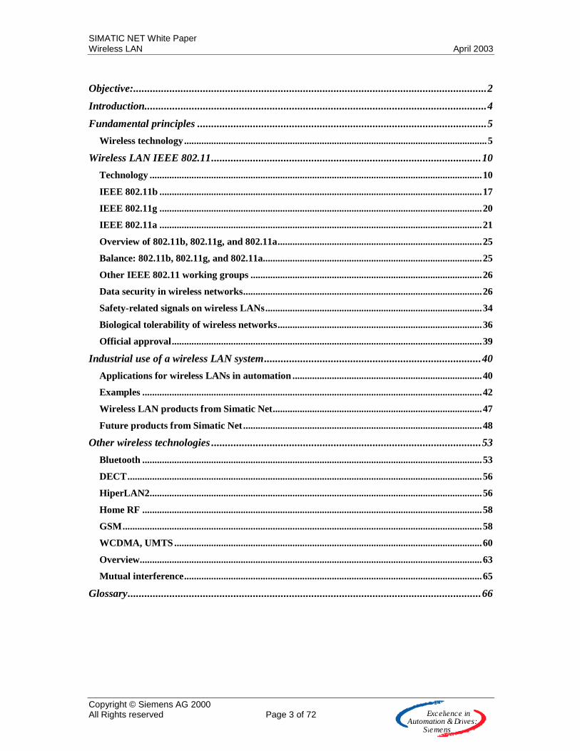
Objective:...............................................................................................................................2
Introduction...........................................................................................................................4
Fundamental principles ........................................................................................................5
Wireless technology...........................................................................................................................5
Wireless LAN IEEE 802.11.................................................................................................10
Technology .......................................................................................................................................10
IEEE 802.11b ...................................................................................................................................17
IEEE 802.11g ...................................................................................................................................20
IEEE 802.11a ...................................................................................................................................21
Overview of 802.11b, 802.11g, and 802.11a...................................................................................25
Balance: 802.11b, 802.11g, and 802.11a.........................................................................................25
Other IEEE 802.11 working groups ..............................................................................................26
Data security in wireless networks.................................................................................................26
Safety-related signals on wireless LANs........................................................................................34
Biological tolerability of wireless networks...................................................................................36
Official approval..............................................................................................................................39
Industrial use of a wireless LAN system..............................................................................40
Applications for wireless LANs in automation .............................................................................40
Examples ..........................................................................................................................................42
Wireless LAN products from Simatic Net.....................................................................................47
Future products from Simatic Net.................................................................................................48
Other wireless technologies .................................................................................................53
Bluetooth ..........................................................................................................................................53
DECT................................................................................................................................................56
HiperLAN2.......................................................................................................................................56
Home RF ..........................................................................................................................................58
GSM..................................................................................................................................................58
WCDMA, UMTS .............................................................................................................................60
Overview...........................................................................................................................................63
Mutual interference.........................................................................................................................65
Glossary...............................................................................................................................66

SIMATIC NET White Paper Wireless LAN April 2003
Copyright © Siemens AG 2000 All Rights reserved Page 4 of 72 E x c e lle n c e in
A u to m a tio n &Driv e s :S ie m e n s
Introduction Wireless networks are becoming more and more popular. In areas as diverse as offices, warehouses and even industrial production facilities, wireless networks provide a new sense of independence and flexibility, resulting in cost benefits in plant installation and operation. All the production data and service data on the wireless network can be simultaneously collected and modified from anywhere in the company. Commissioning engineers can work onsite at the machine and see exactly what they are doing. Different technologies, described in detail below, are available for implementing this new kind of networking and its possible application areas.
SIMATIC NET White Paper Wireless LAN April 2003
Copyright © Siemens AG 2000 All Rights reserved Page 5 of 72 E x c e lle n c e in
A u to m a tio n &Driv e s :S ie m e n s
Fundamental principles
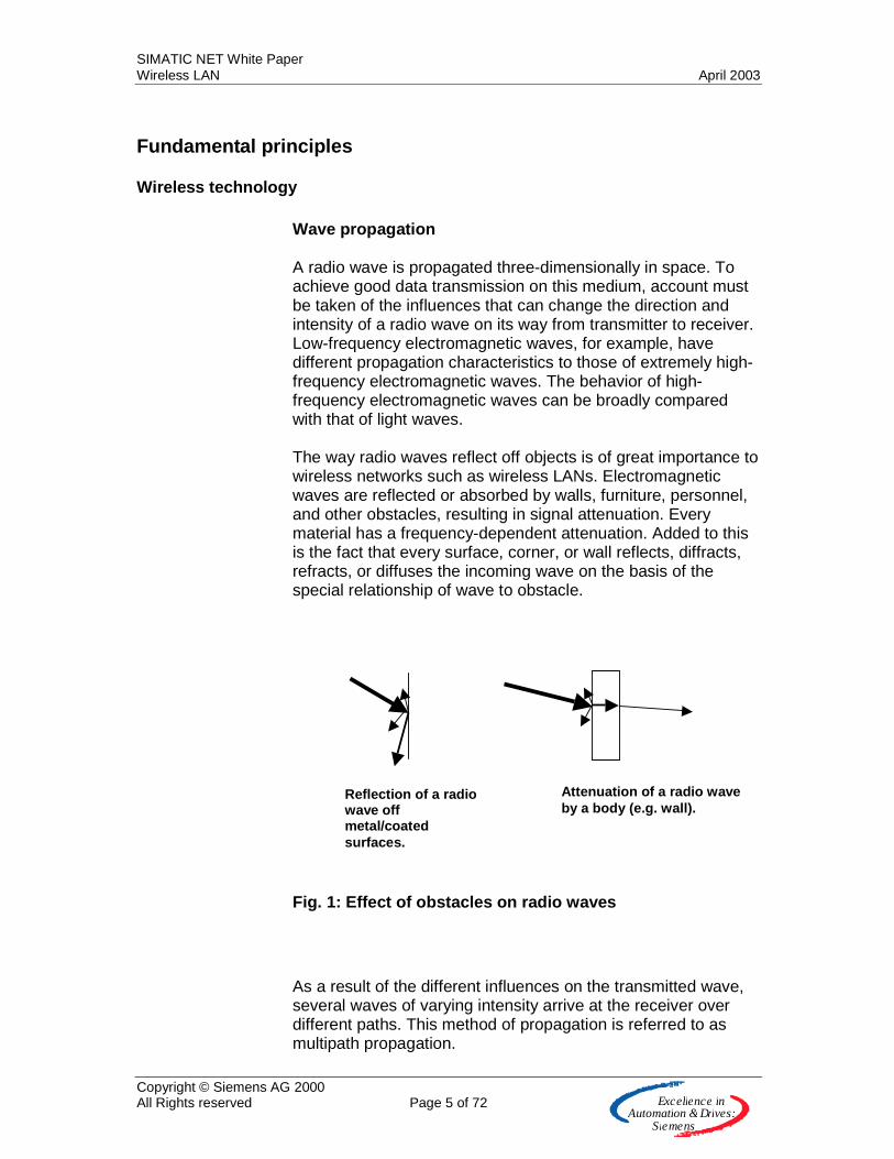
Wireless technology Wave propagation A radio wave is propagated three-dimensionally in space. To achieve good data transmission on this medium, account must be taken of the influences that can change the direction and intensity of a radio wave on its way from transmitter to receiver. Low-frequency electromagnetic waves, for example, have different propagation characteristics to those of extremely high-frequency electromagnetic waves. The behavior of high-frequency electromagnetic waves can be broadly compared with that of light waves. The way radio waves reflect off objects is of great importance to wireless networks such as wireless LANs. Electromagnetic waves are reflected or absorbed by walls, furniture, personnel, and other obstacles, resulting in signal attenuation. Every material has a frequency-dependent attenuation. Added to this is the fact that every surface, corner, or wall reflects, diffracts, refracts, or diffuses the incoming wave on the basis of the special relationship of wave to obstacle.
Fig. 1: Effect of obstacles on radio waves
As a result of the different influences on the transmitted wave, several waves of varying intensity arrive at the receiver over different paths. This method of propagation is referred to as multipath propagation.
Reflection of a radio wave off metal/coated surfaces.
Attenuation of a radio wave by a body (e.g. wall).

SIMATIC NET White Paper Wireless LAN April 2003
Copyright © Siemens AG 2000 All Rights reserved Page 6 of 72 E x c e lle n c e in
A u to m a tio n &Driv e s :S ie m e n s
The resulting heterodyning of waves at the receiver can lead to amplification, attenuation, or, in the worst-case situation, to destruction of the signal, depending on the phase angle of the individual wave. From the environment-dependent signal characteristic, the receiver must select the best and strongest signal. Moving sources of interference, such as persons or automobiles, can continually modify this transmission path. Not only spatial objects present obstacles, however. Adjacent transmitters from other radio systems can also result in deterioration of the wireless link.
Fig. 2: Multipath propagation of radio waves
SIMATIC NET White Paper Wireless LAN April 2003
Copyright © Siemens AG 2000 All Rights reserved Page 7 of 72 E x c e lle n c e in
A u to m a tio n &Driv e s :S ie m e n s
Transmission medium/spectrum In contrast to LANs that use copper or fiber-optic cables, a wireless local network uses space as its transmission medium. Unlike copper or fiber-optic cables, however, wireless networks do not transmit information through variations in voltage values or light pulses, but rather in the form of electromagnetic waves. As a transmission medium, space responds completely differently to cable with its clearly defined and constant transmission characteristics. Due to physical circumstances, the usable frequency spectrum for the transmission of electromagnetic waves on earth is limited. Depending on the output power, any given frequency can be used only once within a specific radius around the transmitter (shared medium).
SIMATIC NET White Paper Wireless LAN April 2003
Copyright © Siemens AG 2000 All Rights reserved Page 8 of 72 E x c e lle n c e in
A u to m a tio n &Driv e s :S ie m e n s
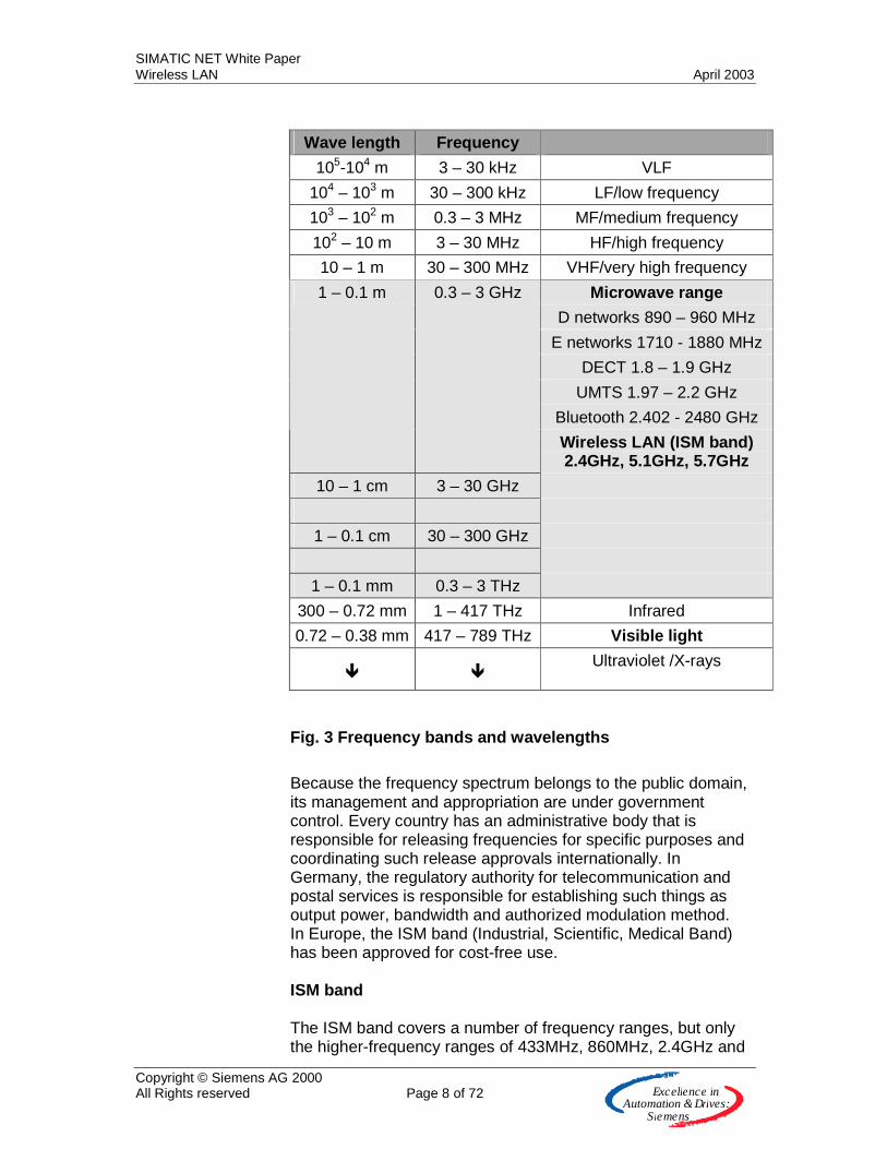
Fig. 3 Frequency bands and wavelengths
Because the frequency spectrum belongs to the public domain, its management and appropriation are under government control. Every country has an administrative body that is responsible for releasing frequencies for specific purposes and coordinating such release approvals internationally. In Germany, the regulatory authority for telecommunication and postal services is responsible for establishing such things as output power, bandwidth and authorized modulation method. In Europe, the ISM band (Industrial, Scientific, Medical Band) has been approved for cost-free use. ISM band The ISM band covers a number of frequency ranges, but only the higher-frequency ranges of 433MHz, 860MHz, 2.4GHz and
Wave length Frequency
105-104 m 3 – 30 kHz VLF
104 – 103 m 30 – 300 kHz LF/low frequency
103 – 102 m 0.3 – 3 MHz MF/medium frequency
102 – 10 m 3 – 30 MHz HF/high frequency
10 – 1 m 30 – 300 MHz VHF/very high frequency
Microwave range
D networks 890 – 960 MHz
E networks 1710 - 1880 MHz
DECT 1.8 – 1.9 GHz
UMTS 1.97 – 2.2 GHz
Bluetooth 2.402 - 2480 GHz
1 – 0.1 m 0.3 – 3 GHz
Wireless LAN (ISM band) 2.4GHz, 5.1GHz, 5.7GHz
10 – 1 cm 3 – 30 GHz
1 – 0.1 cm 30 – 300 GHz
1 – 0.1 mm 0.3 – 3 THz
300 – 0.72 mm 1 – 417 THz Infrared
0.72 – 0.38 mm 417 – 789 THz Visible light
�
� Ultraviolet /X-rays
SIMATIC NET White Paper Wireless LAN April 2003
Copyright © Siemens AG 2000 All Rights reserved Page 9 of 72 E x c e lle n c e in
A u to m a tio n &Driv e s :S ie m e n s
5GHz are suitable for data transmission. An even higher frequency range of 24GHz has not yet been made accessible. While the low-frequency ranges are used for door/gate control systems, alarm systems, audio systems and measured value transmission, only the 2.4GHz and 5.7GHz are of importance for data transmission at the data rates required by LANs.

SIMATIC NET White Paper Wireless LAN April 2003
Copyright © Siemens AG 2000 All Rights reserved Page 10 of 72 E x c e lle n c e in
A u to m a tio n &Driv e s :S ie m e n s
Wireless LAN IEEE 802.11
Technology Standard The family of IEEE 802 standards only describes the two lowest layers (Layer 1 and 2) in the ISO/OSI reference model, the bit transmission layer (Physical Layer, PHY) and the security layer (Data Link Layer). The security layer is further subdivided into the MAC (Medium Access Control) and the LLC (Logical Link Control), with the MAC layer describing the control of access to the medium. 802.3 MAC regulates access to Ethernet and 802.11 MAC regulates access to WLAN. LLC is standardized for all 802 members and makes it possible to use higher-level layers such as TCP/IP (Layer 4 and 3) on the same principle.
Fig. 4: Breakdown of IEEE 802 standards
Following a phase of seven years, the IEEE passed the first standard for wireless LANs (WLANs) in 1997 with 802.11 (note: 802.11 without an additional letter!). It described a standardized MAC layer and three different PHY layers. Frequency hopping (FHSS) and Direct Sequence Spread Spectrum (DSSS) describe two frequency-spreading procedures in the 2.4GHz ISM band that enable data rates of 1 and 2 Mbit/s. In addition, an implementation with infrared technology is suggested that has never been put to practical use.
SIMATIC NET White Paper Wireless LAN April 2003
Copyright © Siemens AG 2000 All Rights reserved Page 11 of 72 E x c e lle n c e in
A u to m a tio n &Driv e s :S ie m e n s
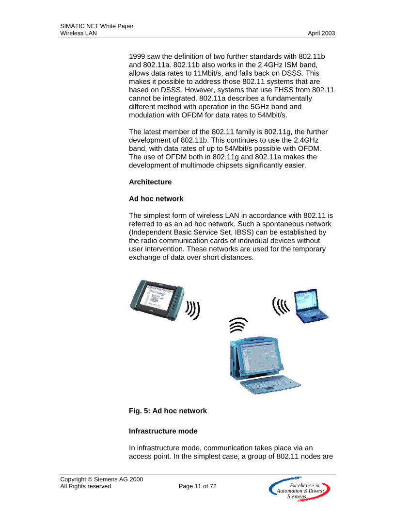
1999 saw the definition of two further standards with 802.11b and 802.11a. 802.11b also works in the 2.4GHz ISM band, allows data rates to 11Mbit/s, and falls back on DSSS. This makes it possible to address those 802.11 systems that are based on DSSS. However, systems that use FHSS from 802.11 cannot be integrated. 802.11a describes a fundamentally different method with operation in the 5GHz band and modulation with OFDM for data rates to 54Mbit/s. The latest member of the 802.11 family is 802.11g, the further development of 802.11b. This continues to use the 2.4GHz band, with data rates of up to 54Mbit/s possible with OFDM. The use of OFDM both in 802.11g and 802.11a makes the development of multimode chipsets significantly easier. Architecture Ad hoc network The simplest form of wireless LAN in accordance with 802.11 is referred to as an ad hoc network. Such a spontaneous network (Independent Basic Service Set, IBSS) can be established by the radio communication cards of individual devices without user intervention. These networks are used for the temporary exchange of data over short distances.
Fig. 5: Ad hoc network
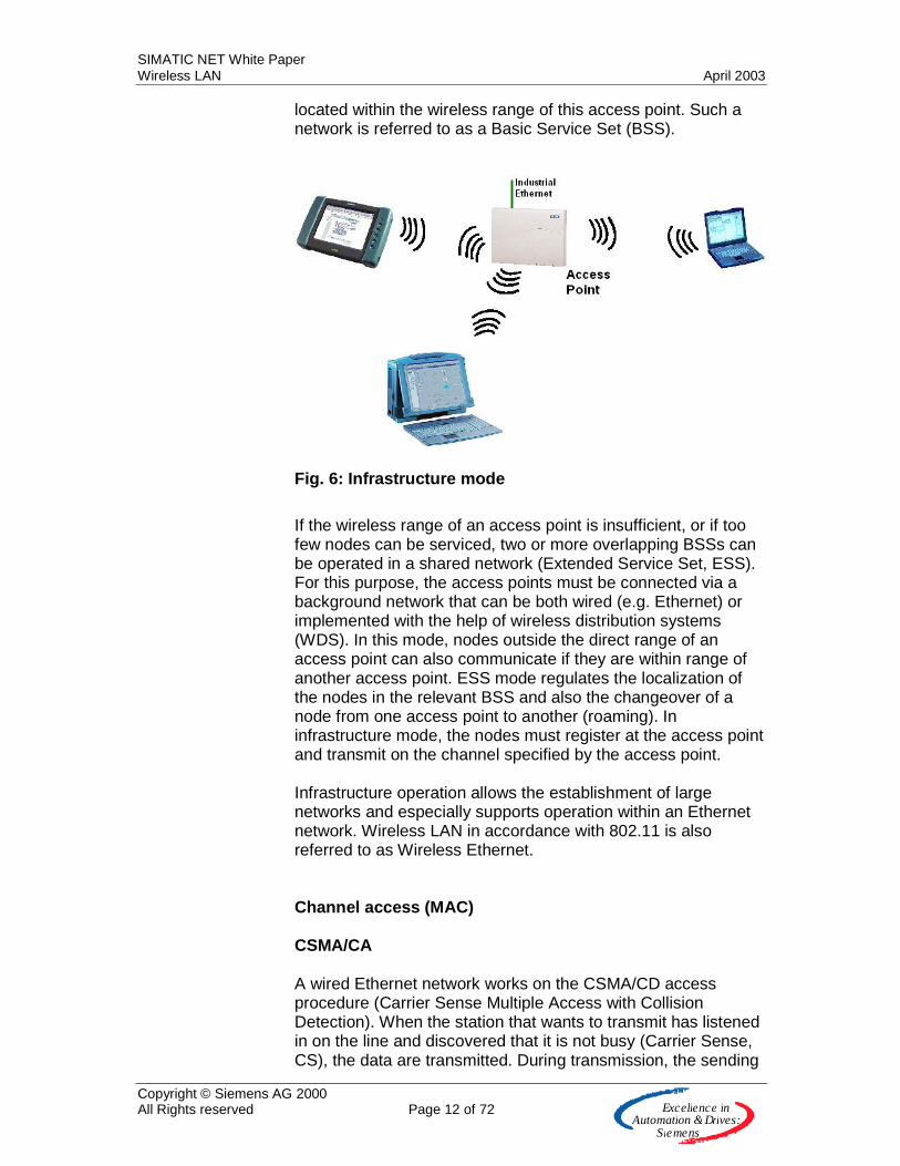
Infrastructure mode In infrastructure mode, communication takes place via an access point. In the simplest case, a group of 802.11 nodes are
SIMATIC NET White Paper Wireless LAN April 2003
Copyright © Siemens AG 2000 All Rights reserved Page 12 of 72 E x c e lle n c e in
A u to m a tio n &Driv e s :S ie m e n s
located within the wireless range of this access point. Such a network is referred to as a Basic Service Set (BSS).
Fig. 6: Infrastructure mode
If the wireless range of an access point is insufficient, or if too few nodes can be serviced, two or more overlapping BSSs can be operated in a shared network (Extended Service Set, ESS). For this purpose, the access points must be connected via a background network that can be both wired (e.g. Ethernet) or implemented with the help of wireless distribution systems (WDS). In this mode, nodes outside the direct range of an access point can also communicate if they are within range of another access point. ESS mode regulates the localization of the nodes in the relevant BSS and also the changeover of a node from one access point to another (roaming). In infrastructure mode, the nodes must register at the access point and transmit on the channel specified by the access point. Infrastructure operation allows the establishment of large networks and especially supports operation within an Ethernet network. Wireless LAN in accordance with 802.11 is also referred to as Wireless Ethernet. Channel access (MAC) CSMA/CA A wired Ethernet network works on the CSMA/CD access procedure (Carrier Sense Multiple Access with Collision Detection). When the station that wants to transmit has listened in on the line and discovered that it is not busy (Carrier Sense, CS), the data are transmitted. During transmission, the sending
SIMATIC NET White Paper Wireless LAN April 2003
Copyright © Siemens AG 2000 All Rights reserved Page 13 of 72 E x c e lle n c e in
A u to m a tio n &Driv e s :S ie m e n s
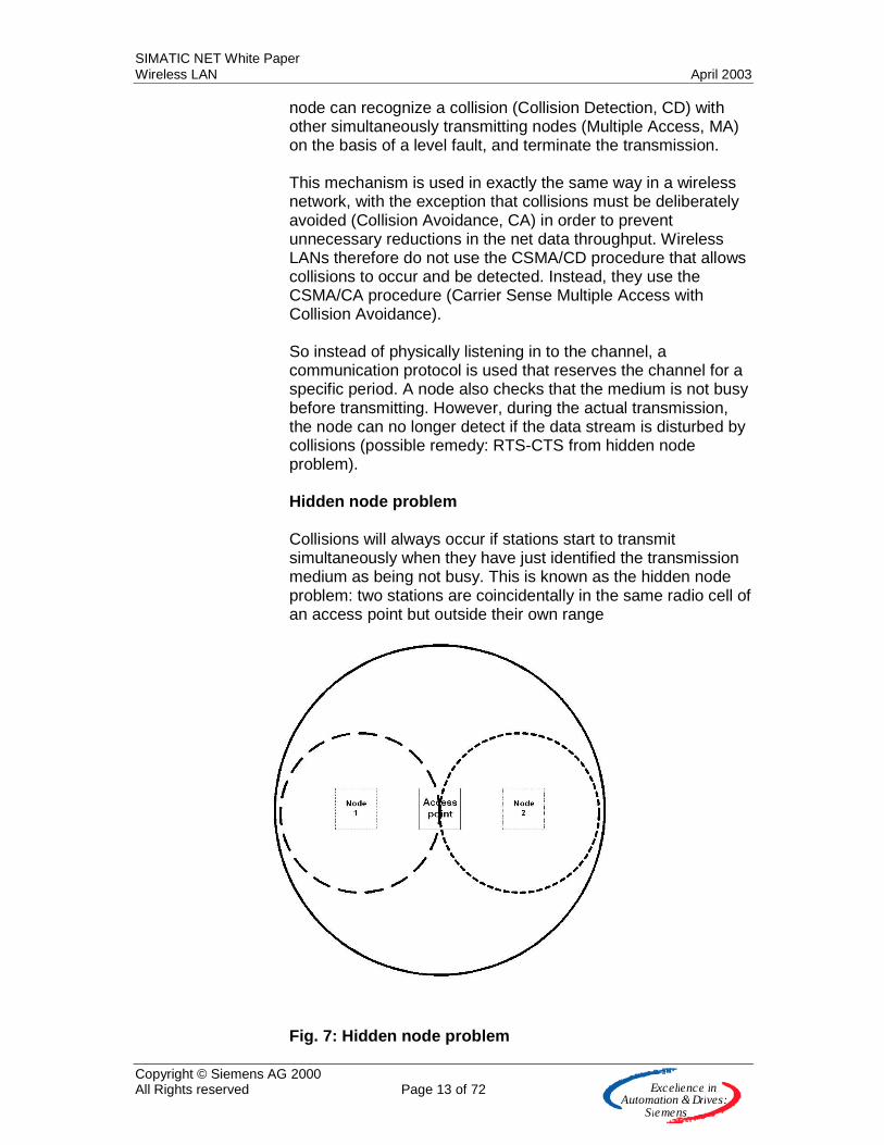
node can recognize a collision (Collision Detection, CD) with other simultaneously transmitting nodes (Multiple Access, MA) on the basis of a level fault, and terminate the transmission. This mechanism is used in exactly the same way in a wireless network, with the exception that collisions must be deliberately avoided (Collision Avoidance, CA) in order to prevent unnecessary reductions in the net data throughput. Wireless LANs therefore do not use the CSMA/CD procedure that allows collisions to occur and be detected. Instead, they use the CSMA/CA procedure (Carrier Sense Multiple Access with Collision Avoidance). So instead of physically listening in to the channel, a communication protocol is used that reserves the channel for a specific period. A node also checks that the medium is not busy before transmitting. However, during the actual transmission, the node can no longer detect if the data stream is disturbed by collisions (possible remedy: RTS-CTS from hidden node problem). Hidden node problem Collisions will always occur if stations start to transmit simultaneously when they have just identified the transmission medium as being not busy. This is known as the hidden node problem: two stations are coincidentally in the same radio cell of an access point but outside their own range
Fig. 7: Hidden node problem
SIMATIC NET White Paper Wireless LAN April 2003
Copyright © Siemens AG 2000 All Rights reserved Page 14 of 72 E x c e lle n c e in
A u to m a tio n &Driv e s :S ie m e n s
The RTS-CTS (Request to send, Clear to send) handshake procedure specified in 802.11 provides a remedy here with special message frames that reserve the airspace for the station that is ready to transmit. It must be noted that although RTS-CTS is an optional operating mode, all devices must have the capability. It is only used in constellations where otherwise an acceptable data throughput would not be achieved. Once the station that is ready to transmit has detected that the medium as free, it sends an RTS (Request to Send) frame to the partner station. This message reserves the medium (airspace) for one complete data transmission (RTS message frame, CTS message frame, data frame, acknowledgement message, and intervals). Within a specified time, the partner station sends back a CTS (Clear to Send) frame, and the total remaining time for the now ongoing data transmission is also specified. Every node now knows how long the ongoing data transmission will take. Because the CTS and RTS frames are short, their loss due to a collision is highly unlikely. If the partner station receives the CTS message correctly, the data transmission can begin. When the data transmission has been completed, an ACK (Acknowledgement) frame tells the sender that the data were transmitted successfully. If no acknowledgement is received, the sending station must assume that a collision or a transmission error has occurred. After a waiting time has elapsed, the sending station makes a new attempt to send. This handshake procedure, which is also forwarded over the access point, makes it possible to reach stations that do not lie within the range of the transmitting station (hidden node). These stations also recognize that the transmission medium has been reserved. Deterministic features A system that works in accordance with the 802.11 MAC layer is initially not deterministic and allocates access according to statistical procedures. To be able to support time-critical services, 802.11 defines the Point Coordinated Function (PCF). Although implementation of the PCF in the nodes is only optional, all nodes must observe the necessary rules if required, and comply with access allocation by the access point during the contention-free period (CFP). Only during the subsequent contention period (CP) are all nodes allowed to work according to the familiar CSM/CA procedure.

SIMATIC NET White Paper Wireless LAN April 2003
Copyright © Siemens AG 2000 All Rights reserved Page 15 of 72 E x c e lle n c e in
A u to m a tio n &Driv e s :S ie m e n s
Fig. 8: Allocation of access to the medium with PCF
As can be seen from Fig. 8: Allocation of access to the medium with PCF, nodes 1, 2 and 3 regularly have the opportunity to transmit data in the CFP periods since the access point allocates authorization for this. Node 4 only gets one opportunity because it must compete with nodes 5 and 6 for access during the contention period (CP). Fragmentation If a node has been allocated access to the channel, it can transmit up to 2312 bytes of user data in one frame. At 11Mbit/s, this takes almost 2 ms. To increase the probability of error-free transfer of a frame, 802.11 offers the fragmentation mechanism. The user can define a maximum value for user data to be transferred within one frame. This naturally also increases the protocol overhead and reduces net data throughput, but faults then have nowhere near their original powerful effect. Bit transmission (PHY) Frequency hopping spread spectrum The frequency hopping spread spectrum procedure (FHSS) transmits the signal over 1MHz-wide channels with permanently changing frequencies (frequency hopping). The frequency hopping takes place in a rhythm familiar to the receiver, that is, sender and receiver must be synchronized prior to data transmission. The sender has 79 overlap-free channels in the 2.4GHZ ISM band for frequency hopping, bringing together 3 groups with 26 patterns each (USA, Europe). Gaussian phase shift keying (GFSK) is used for modulation. The FHSS method is not easily susceptible to interference, as carrier frequencies with strong narrow-band interference sources can be left out and the data retransmitted with the aid of other carrier frequencies. The FHSS procedure provides data rates of between 1 and 2 Mbit/s only, so this procedure is only
SIMATIC NET White Paper Wireless LAN April 2003
Copyright © Siemens AG 2000 All Rights reserved Page 16 of 72 E x c e lle n c e in
A u to m a tio n &Driv e s :S ie m e n s
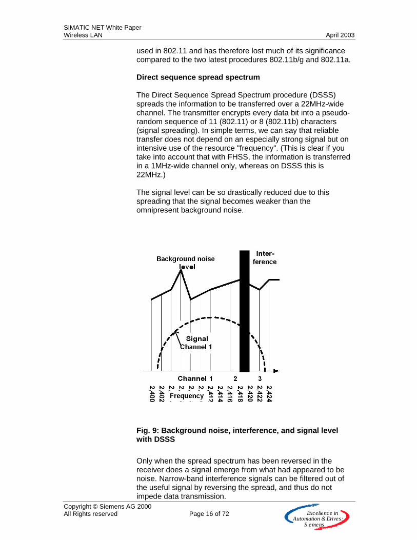
used in 802.11 and has therefore lost much of its significance compared to the two latest procedures 802.11b/g and 802.11a. Direct sequence spread spectrum The Direct Sequence Spread Spectrum procedure (DSSS) spreads the information to be transferred over a 22MHz-wide channel. The transmitter encrypts every data bit into a pseudo-random sequence of 11 (802.11) or 8 (802.11b) characters (signal spreading). In simple terms, we can say that reliable transfer does not depend on an especially strong signal but on intensive use of the resource "frequency". (This is clear if you take into account that with FHSS, the information is transferred in a 1MHz-wide channel only, whereas on DSSS this is 22MHz.) The signal level can be so drastically reduced due to this spreading that the signal becomes weaker than the omnipresent background noise.
Fig. 9: Background noise, interference, and signal level with DSSS
Only when the spread spectrum has been reversed in the receiver does a signal emerge from what had appeared to be noise. Narrow-band interference signals can be filtered out of the useful signal by reversing the spread, and thus do not impede data transmission.
SIMATIC NET White Paper Wireless LAN April 2003
Copyright © Siemens AG 2000 All Rights reserved Page 17 of 72 E x c e lle n c e in
A u to m a tio n &Driv e s :S ie m e n s
By spreading the useful signal over a bandwidth of more than 22MHz, much higher transmission speeds can be attained with this method than with the FHSS procedure, in which a bandwidth of only 1MHz is available. Wideband transmission also has the advantage of eliminating interference caused by multipath reception, as frequency-specific propagation does not have as much of an effect. The DSSS method is thus virtually impervious to narrow-band interference sources, offers better protection against multipath propagation, and enables higher data throughput. DSSS is used in 802.11b. Orthogonal Frequency Division Multiplexing In Orthogonal Frequency Division Multiplexing (OFDM), orthogonal subcarriers (frequencies) are combined into one channel and transmitted by the sender as a cumulative signal. Orthogonal means that the different subcarriers are selected in such a way that their spectrum is at a minimum just where another subcarrier provides its information. With Wireless LAN 802.11a, 52 subcarriers are defined in each channel at an interval of 0.3125MHz from each other. The information to be transmitted is now distributed among these subcarriers, assigned redundant bits for strong Forward Error Correction (FEC), and then transmitted. This means that the procedure is highly impervious to multipath propagation and narrow-band interference, and is of particular interest for industrial applications. OFDM is used on 802.11a and is also used with the new 802.11g standard.
IEEE 802.11b Timescales 802.11b is the only standard to be adopted conclusively by the IEEE at the present time and approved by the regulation bodies of the countries (conditionally in some cases). Frequencies, channels In the 2.4GHz band, there are 13 specified channels (frequency ranges with a width of 5MHz) that must be set by the user for operating an access point (US: 11 channels). This frequency is then valid in the entire effective range of the access point. When using products in accordance with 802.11b, a maximum of 3 can be used without overlap at one location because the transfer of data requires a signal with a width of 22MHz.
SIMATIC NET White Paper Wireless LAN April 2003
Copyright © Siemens AG 2000 All Rights reserved Page 18 of 72 E x c e lle n c e in
A u to m a tio n &Driv e s :S ie m e n s
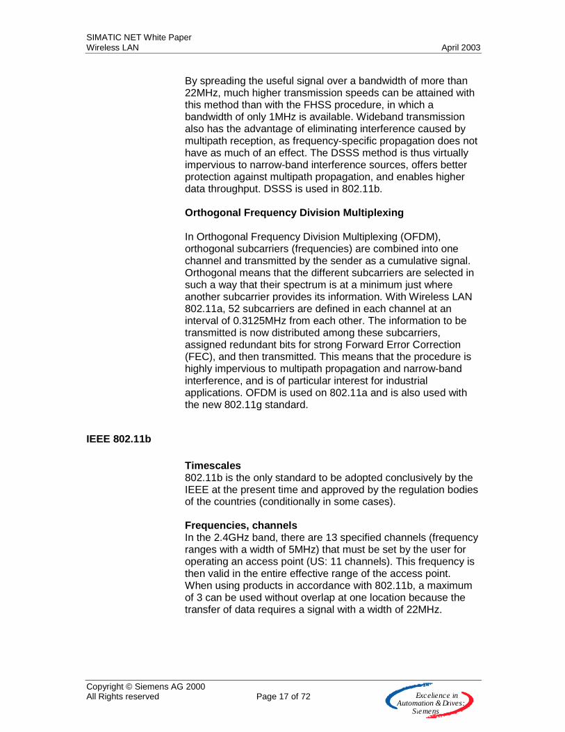
Fig. 10: Non-overlapping channels for DSSS in the 2.4GHz band
As can be seen from Fig. 10: Non-overlapping channels for DSSS in the 2.4GHz band, channels 1, 6 and 11 can be operated without overlap and also offer an interval of 3MHz from each other. This is also the ideal combination in countries where only channels 1 to 11 are enabled (e.g. the US). In countries that permit channels 1 to 13, other combinations with even greater intervals can be operated (for example, Europe with channels 1, 7 and 13). Up to 3 different channels can thus be operated at one location without any reciprocal effect. The number of available non-overlapping channels is particularly important at the boundaries of a wireless cell where an automatic switchover is made to the other channel of the neighboring wireless cell. In order to prevent noise and interference at this boundary, the channels of the wireless cells must not overlap.
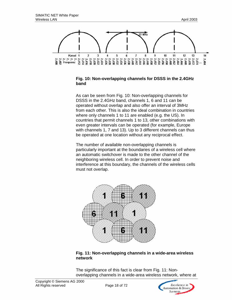
Fig. 11: Non-overlapping channels in a wide-area wireless network
The significance of this fact is clear from Fig. 11: Non-overlapping channels in a wide-area wireless network, where at
SIMATIC NET White Paper Wireless LAN April 2003
Copyright © Siemens AG 2000 All Rights reserved Page 19 of 72 E x c e lle n c e in
A u to m a tio n &Driv e s :S ie m e n s
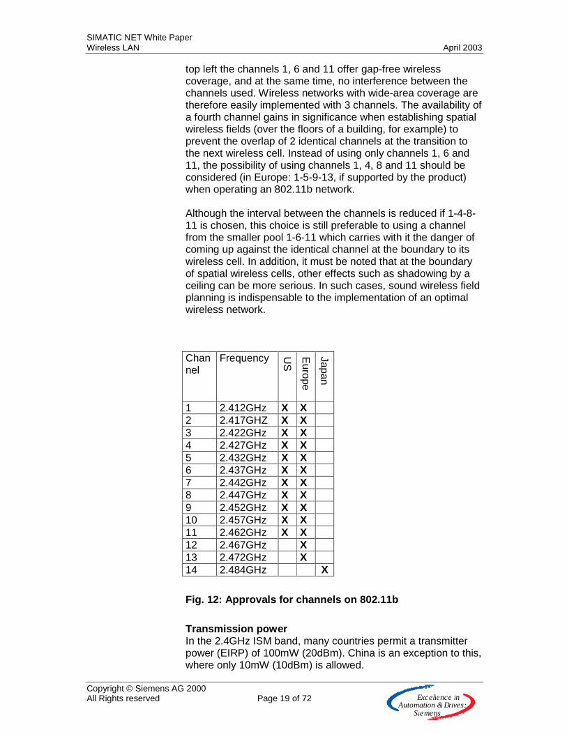
top left the channels 1, 6 and 11 offer gap-free wireless coverage, and at the same time, no interference between the channels used. Wireless networks with wide-area coverage are therefore easily implemented with 3 channels. The availability of a fourth channel gains in significance when establishing spatial wireless fields (over the floors of a building, for example) to prevent the overlap of 2 identical channels at the transition to the next wireless cell. Instead of using only channels 1, 6 and 11, the possibility of using channels 1, 4, 8 and 11 should be considered (in Europe: 1-5-9-13, if supported by the product) when operating an 802.11b network. Although the interval between the channels is reduced if 1-4-8-11 is chosen, this choice is still preferable to using a channel from the smaller pool 1-6-11 which carries with it the danger of coming up against the identical channel at the boundary to its wireless cell. In addition, it must be noted that at the boundary of spatial wireless cells, other effects such as shadowing by a ceiling can be more serious. In such cases, sound wireless field planning is indispensable to the implementation of an optimal wireless network. Channel
Frequency US
Europe
Japan
1 2.412GHz X X 2 2.417GHZ X X 3 2.422GHz X X 4 2.427GHz X X 5 2.432GHz X X 6 2.437GHz X X 7 2.442GHz X X 8 2.447GHz X X 9 2.452GHz X X 10 2.457GHz X X 11 2.462GHz X X 12 2.467GHz X 13 2.472GHz X 14 2.484GHz X
Fig. 12: Approvals for channels on 802.11b
Transmission power In the 2.4GHz ISM band, many countries permit a transmitter power (EIRP) of 100mW (20dBm). China is an exception to this, where only 10mW (10dBm) is allowed.
SIMATIC NET White Paper Wireless LAN April 2003
Copyright © Siemens AG 2000 All Rights reserved Page 20 of 72 E x c e lle n c e in
A u to m a tio n &Driv e s :S ie m e n s
Data transfer rate 802.11b transmits data at a rate of 11Mbit/s. It must be noted, however, that after the packet headers and protocol overhead have been subtracted, the net data rate can scarcely exceed 5Mbit/s. If the bit error rate in the wireless network increases, the access point automatically switches first to 5.5Mbit/s, then to 2Mbit/s, and finally to 1Mbit/s. This strategy is an attempt to maintain the connection as long as possible and to strike a compromise in the data rate. Ranges It is difficult to provide generally valid information on the range of a wireless LAN. To begin with, it is extremely important to know the transmitter power with which the products in question work. There are vendors here with 20dBm products, but also vendors with only 15dBm, for whom low current consumption is important. Furthermore, the gain of the antenna used including antenna cable and lightning protection must be taken into account. Another important factor is the environment in which the wireless network is established. Reflections off metal objects with multipath propagation, signal attenuation caused by walls and doors, interference from faulty products, and also interference from correctly operated products that use the same frequency band, all have significant effects. If a commercially available 15dBm PCMCIA wireless card is used, a distance of 30m can be achieved in the indoor area and 100m in the outdoor area. These values can deteriorate by a factor of 2 under the influence of the restrictions listed above.
IEEE 802.11g Timescales In the case of 802.11g, the final version of the IEEE is expected in May 2003. Following this timescale, the regulating bodies are expected to release the standard quickly since 802.11g is the compatible further development of 802.11b in the same frequency band. Frequencies, channels Because 802.11g is fully compatible with 802.11b and is its further development, exactly the same frequencies and channels are used. Transmission power Transmission power is 100mW (20dBm) EIRP, as with 802.11b.
SIMATIC NET White Paper Wireless LAN April 2003
Copyright © Siemens AG 2000 All Rights reserved Page 21 of 72 E x c e lle n c e in
A u to m a tio n &Driv e s :S ie m e n s
Data transfer rate Data rates of up to 54Mbit/s are specified on 802.11g, thanks to modulation with OFDM. Just as with 802.11b, this is reduced step-by-step as wireless conditions deteriorate (fall back to 54, 36, 33, 24, 22, 12, 11, 9, 6, 5.5, 2, 1Mbit/s). Data rates of 11Mbit/s and slower are fully compatible with 802.11b. Ranges With the relevant data rates, ranges are very similar to those of 802.11b, but they fall significantly in the case of a bandwidth of 54Mbit/s.
IEEE 802.11a Timescales The IEEE has already passed 802.11a in the 5GHz frequency band in 1999 (as 802.11b!), but release by the regulating bodies of the different countries follows different timescales and is subject to different conditions in the case of permissible frequency channels and transmitter power. HiperLAN2, standardized by ETSI and in competition with IEEE 802.11, was long backed in Europe in particular. In the US, 802.11a products have also been available since the end of 2001 without additional official requirements. Some European countries have already approved 11a in 2002 and an overall European solution is expected during the course of 2003. Frequencies, channels 802.11a offers a higher number of available wireless channels that must be set by the user for operating an access point. This frequency is then valid in the entire effective range of the access point. This fact is very interesting for wireless networks with a high information density (for example, corporate networks or hot spots). In addition, there are significantly fewer different applications active in the 5GHz band (for example, flight navigation or radar equipment) than in the 2.4GHz band that belongs to the ISM (Industrial, Scientific, Medical) bands and is also intensively used by the relevant groups. Unfortunately, 802.11b and 802.11a are not compatible since they are operated in different frequency ranges. Different vendors are working on multimode solutions that will fulfill both standards with one product. In the 5GHz frequency band, it must be noted that widely differing national regulations exist that are currently subject to great changes due to the success of wireless LANs.

SIMATIC NET White Paper Wireless LAN April 2003
Copyright © Siemens AG 2000 All Rights reserved Page 22 of 72 E x c e lle n c e in
A u to m a tio n &Driv e s :S ie m e n s
Frequency range/GHz Bandwidth Non-overlapping channels
5.15 ... 5.25 100MHz 4 5.25 ... 5.35 100MHz 4 5.725 ... 5.825 100MHz 4
Fig. 13: Frequency ranges in the 5GHz ISM band
In Europe, operation is even feasible between 5.470GHz and 5.725GHz, a range previously allocated only to HiperLAN2. It must be noted that these different frequency bands must also be supported by the relevant products. The range 5.250 to 5.350GHz is extremely significant here since it is available in all countries of the world. All component vendors currently support the range 5.15 to 5.35GHz. In Germany, the range between 5.150GHz and 5.250GHz has already been released by RegTP provided certain conditions are observed.
Fig. 14: Channels on 802.11a in the 5GHz band
Transmission power Just as in the case of the significant changes in the official approvals for the frequency bands, the permissible transmitter power is also subject to great change at the present time. 50mW EIRP is currently permitted in Germany in the range 5.15GHz to 5.35GHz, but this power will increase to 200mW EIRP if automatic Transmission Power Control (TPC) and Dynamic Frequency Selection (DFS) are implemented on the device. In Europe, the frequencies of HiperLAN2 are additionally available between 5.47GHz and 5.725Ghz. These permit transmitter power levels of up to 1W (indoor and outdoor). 4W are even permissible between 5.725GHz and 5.825GHz. However, there are currently no products available in these frequency ranges.
SIMATIC NET White Paper Wireless LAN April 2003
Copyright © Siemens AG 2000 All Rights reserved Page 23 of 72 E x c e lle n c e in
A u to m a tio n &Driv e s :S ie m e n s
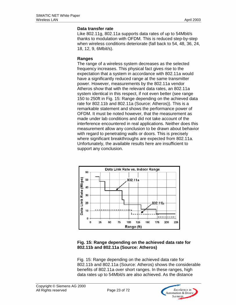
Data transfer rate Like 802.11g, 802.11a supports data rates of up to 54Mbit/s thanks to modulation with OFDM. This is reduced step-by-step when wireless conditions deteriorate (fall back to 54, 48, 36, 24, 18, 12, 9, 6Mbit/s). Ranges The range of a wireless system decreases as the selected frequency increases. This physical fact gives rise to the expectation that a system in accordance with 802.11a would have a significantly reduced range at the same transmitter power. However, measurements by the 802.11a vendor Atheros show that with the relevant data rates, an 802.11a system identical in this respect, if not even better (see range 150 to 250ft in Fig. 15: Range depending on the achieved data rate for 802.11b and 802.11a (Source: Atheros)). This is a remarkable statement and shows the performance power of OFDM. It must be noted however, that the measurement as made under lab conditions and did not take account of the interference encountered in real applications. Neither does this measurement allow any conclusion to be drawn about behavior with regard to penetrating walls or doors. This is precisely where significant breakthroughs are expected from 802.11a. Unfortunately, the available results here are insufficient to support any conclusion.
Fig. 15: Range depending on the achieved data rate for 802.11b and 802.11a (Source: Atheros)
Fig. 15: Range depending on the achieved data rate for 802.11b and 802.11a (Source: Atheros) shows the considerable benefits of 802.11a over short ranges. In these ranges, high data rates up to 54Mbit/s are also achieved. As the distance
SIMATIC NET White Paper Wireless LAN April 2003
Copyright © Siemens AG 2000 All Rights reserved Page 24 of 72 E x c e lle n c e in
A u to m a tio n &Driv e s :S ie m e n s
increases, the achievable data rate sinks significantly to the level of 802.11b at approximately 150ft.

SIMATIC NET White Paper Wireless LAN April 2003
Copyright © Siemens AG 2000 All Rights reserved Page 25 of 72 E x c e lle n c e in
A u to m a tio n &Driv e s :S ie m e n s
Overview of 802.11b, 802.11g, and 802.11a 802.11b 802.11g 802.11a Frequency band 2.4GHz 2.4GHz 5GHz Data rate 11Mbit/s 54Mbit/s 54Mbit/s Non-overlapping channels
3 3 4, 8
Data rate (outdoor) to 1m 10m 100m
11Mbit/s 11Mbit/s 1Mbit/s
54Mbit/s x1 x1
54Mbit/s 36Mbit/s 6Mbit/s
Modulation DSSS OFDM OFDM Penetration of walls Medium Medium Poor Reflections, e.g. off metal objects
Robust x1 Robust
Danger of interference from other wireless applications
Medium Medium Low
X1: Statement not yet possible today
Fig. 16: Overview of the current standards on 802.11
Balance: 802.11b, 802.11g, and 802.11a In the long term, the significance of 802.11b will diminish since it will become part of the fully compatible standard 802.11g. For this reason, the question of which wireless technology to choose will be restricted to 802.11g and 802.11a. The speed with which this change will take place is difficult to predict since it depends heavily on the vendors of chipsets and on the high-volume applications (such as WLAN in laptops). With operation at 5GHz, 802.11a offers clear benefits if a frequency band is required that is rarely to be found in other wireless systems. Unfortunately, due to the great popularity of the 2.4GHz band on 802.11b and 802.11g, this is not case. On the other hand, the continued use of the 2.4GHz band on 802.11g enables good migration from 802.11b users. Such users would otherwise have to switch to 11a at 5GHz when making the step to higher bandwidths.
SIMATIC NET White Paper Wireless LAN April 2003
Copyright © Siemens AG 2000 All Rights reserved Page 26 of 72 E x c e lle n c e in
A u to m a tio n &Driv e s :S ie m e n s
802.11a is suitable for applications with high information density requirements. In such cases, not only can data rates of 54Mbit/s be achieved, but 4 (in some cases up to 8) channels can be operated at one location. 54Mbit/s are also possible with 802.11g but "only" 3 channels. By using the 2.4GHz band, 802.11g gains advantages over 802.11a in terms of range since wave propagation deteriorates as frequency increases. Chipset vendors counter this uncertainty by offering multimode chipsets that support both 802.11g and 802.11a depending on how they are configured. This is facilitated by the use of OFDM in both standards.
Other IEEE 802.11 working groups
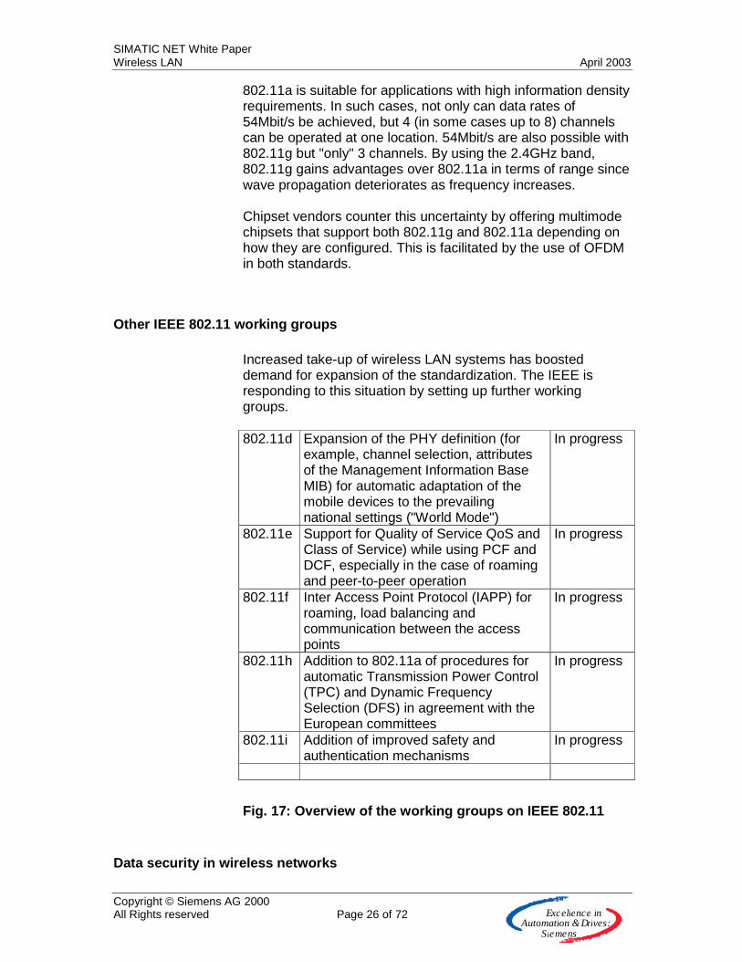
Increased take-up of wireless LAN systems has boosted demand for expansion of the standardization. The IEEE is responding to this situation by setting up further working groups. 802.11d Expansion of the PHY definition (for
example, channel selection, attributes of the Management Information Base MIB) for automatic adaptation of the mobile devices to the prevailing national settings ("World Mode")
In progress
802.11e Support for Quality of Service QoS and Class of Service) while using PCF and DCF, especially in the case of roaming and peer-to-peer operation
In progress
802.11f Inter Access Point Protocol (IAPP) for roaming, load balancing and communication between the access points
In progress
802.11h Addition to 802.11a of procedures for automatic Transmission Power Control (TPC) and Dynamic Frequency Selection (DFS) in agreement with the European committees
In progress
802.11i Addition of improved safety and authentication mechanisms
In progress
Fig. 17: Overview of the working groups on IEEE 802.11
Data security in wireless networks

SIMATIC NET White Paper Wireless LAN April 2003
Copyright © Siemens AG 2000 All Rights reserved Page 27 of 72 E x c e lle n c e in
A u to m a tio n &Driv e s :S ie m e n s
Shared Medium It is possible to break into WLANs because radio waves are not restricted to a fixed medium such as a cable, and because effects such as reflections and diffractions overlap. Added to this is the fact that WLANs are a shared medium, meaning that nodes attempt to access the same network infrastructure. This is not the case with wired switched Ethernet. There, each node receives an exclusive line right up to the switch and it does not have to share this with any other. This difference explains a central problem. You can never be certain as to who is on the wireless network and accessing the medium because in principle, everyone is permitted if no additional measures are taken. Added to this is the fact that the 802.11b transmission protocol contains components that make it easier for unwanted nodes to penetrate the network. This includes the transmission of keys in plaintext, but also the regular broadcasting of the "Service Set Identifier" address (SSID). And the MAC addresses (ACLs) of approved clients are also transmitted over the air in plaintext. Nevertheless, WLAN already possesses some hurdles for protecting against unwanted guests that the hacker must first overcome. Security in the physical layer Although the DSSS (Direct Sequence Spread Spectrum) procedure in IEEE 802.11b has its origins in the military area and the transmitter power is distributed across a wide spectrum, this is not sufficient in itself for secrecy. While the (searching) beam antenna of an attacker no longer finds the narrow-band power peaks of other transmission methods, because the transmitter power is reduced below noise level, nevertheless all encryption methods are known globally and standardized in IEEE 802.11b. In principle, therefore, an 802.11b terminal device can detect any of these transmitters. Nevertheless: locating the transmitter and the alignment of a beam antenna is difficult. Logic protection – SSID, ACL, WEP At the communication level, WLAN has three mechanisms designed to prevent penetration of the network. SSID, Access Control List, and WEP (Wired Equivalent Privacy). Any WLAN comprising one or several access points learns a unique name, the SSID. This SSID is known to the access points (APs) and all terminal devices, and in many configurations it is also broadcast regularly in plaintext. This setting in the configuration of the access point can be very easily deactivated and the name of the network will then remain secret: This is a hurdle that any potential intruder must first overcome.
SIMATIC NET White Paper Wireless LAN April 2003
Copyright © Siemens AG 2000 All Rights reserved Page 28 of 72 E x c e lle n c e in
A u to m a tio n &Driv e s :S ie m e n s
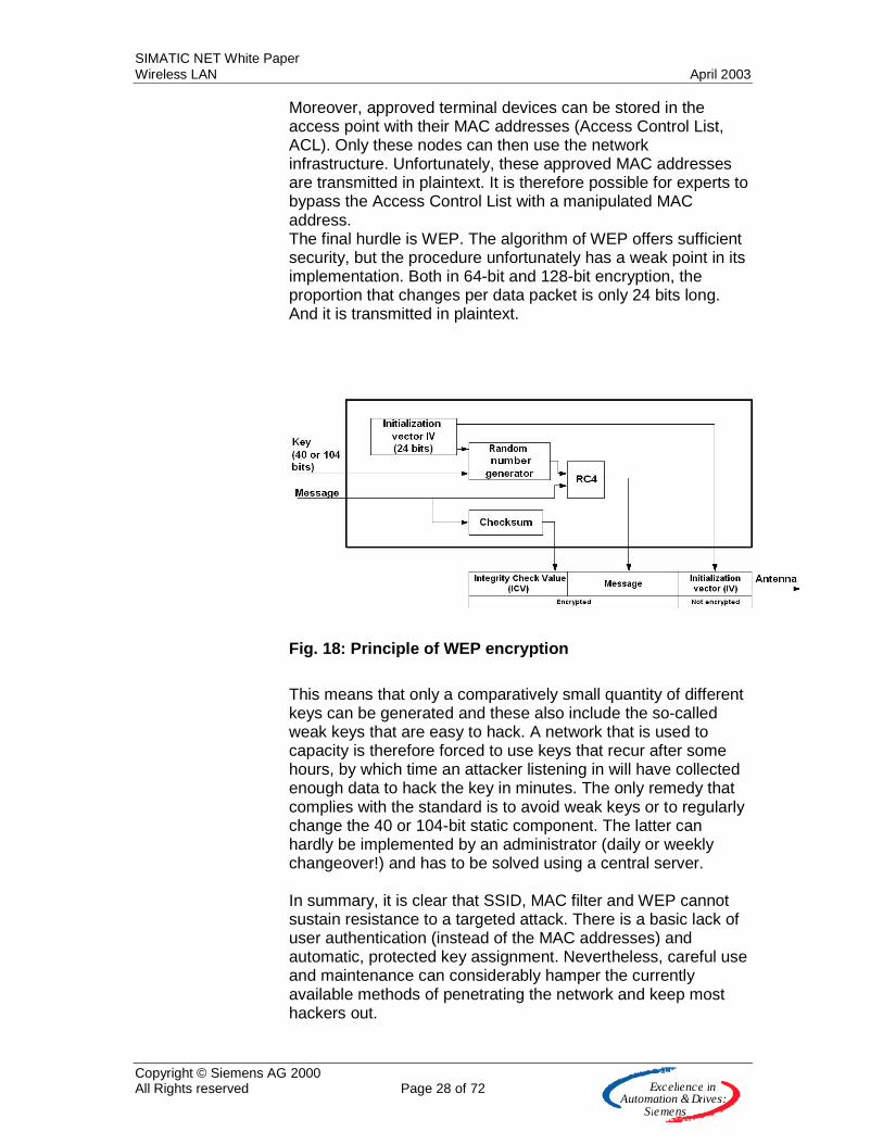
Moreover, approved terminal devices can be stored in the access point with their MAC addresses (Access Control List, ACL). Only these nodes can then use the network infrastructure. Unfortunately, these approved MAC addresses are transmitted in plaintext. It is therefore possible for experts to bypass the Access Control List with a manipulated MAC address. The final hurdle is WEP. The algorithm of WEP offers sufficient security, but the procedure unfortunately has a weak point in its implementation. Both in 64-bit and 128-bit encryption, the proportion that changes per data packet is only 24 bits long. And it is transmitted in plaintext.
Fig. 18: Principle of WEP encryption
This means that only a comparatively small quantity of different keys can be generated and these also include the so-called weak keys that are easy to hack. A network that is used to capacity is therefore forced to use keys that recur after some hours, by which time an attacker listening in will have collected enough data to hack the key in minutes. The only remedy that complies with the standard is to avoid weak keys or to regularly change the 40 or 104-bit static component. The latter can hardly be implemented by an administrator (daily or weekly changeover!) and has to be solved using a central server. In summary, it is clear that SSID, MAC filter and WEP cannot sustain resistance to a targeted attack. There is a basic lack of user authentication (instead of the MAC addresses) and automatic, protected key assignment. Nevertheless, careful use and maintenance can considerably hamper the currently available methods of penetrating the network and keep most hackers out.
SIMATIC NET White Paper Wireless LAN April 2003
Copyright © Siemens AG 2000 All Rights reserved Page 29 of 72 E x c e lle n c e in
A u to m a tio n &Driv e s :S ie m e n s
What is the way forward for 802.11i To provide the highest level of data security for wireless LANs too, intensive thought is going into new cryptography procedures for WLANs within IEEE 802.11i. TKIP TKIP (Temporal Key Integrity Protocol, previously known under WEP 2) is at an advanced stage of development. In principle, this generates a 128-bit key and uses it for encryption. The RC4 algorithm, known as WEP, is retained. However, in contrast to WEP, the dynamic component of the key is double the length at 48 bits, and the key is generated in two phases. In this way, "weak" keys are not created and nor is the supply of different keys used up too quickly. In addition, a long key does not require to be replaced as frequently as a short key. In many cases, it will even be possible to avoid changing the key at all. A crucial benefit for users is that this procedure only requires the renewal of the firmware in the access points and the drivers for the PC cards. MIC A supplementary component is the execution of a Message Integrity Check (MIC) that checks the reliability of the data. MIC is a further development of the Integrity Check Value (ICV, see Fig. 18: Principle of WEP encryption) from 802.11b. There, every data packet is provided with a consecutive number and transferred together with the packet in the encrypted section. The receiver rejects packets that do not match this consecutive number. This procedure is extremely robust against known attacks. AES Activities in 802.11i concentrate additionally on the new encryption standard AES (Advanced Encryption Standard), on which work is still in the early phases. AES supports symmetrical encryption procedures to 256 bits. Since AES is based on adapting the hardware, an upgrade for existing devices is not expected. However, compatibility with the existing security measures on 802.11 is an important goal. Access control In addition to TKIP, IEEE 802.11i overlays the use of IEEE 802.1x for access control (authentication). This standard describes port-based access control to networks. However, this must still be underlayed with a protocol such as EAP (Extensible Authentication Protocol).

SIMATIC NET White Paper Wireless LAN April 2003
Copyright © Siemens AG 2000 All Rights reserved Page 30 of 72 E x c e lle n c e in
A u to m a tio n &Driv e s :S ie m e n s
Fig. 19: Access control with 802.1x
The idea of 802.1x consists of assigning two logical ports (controlled und uncontrolled port) to one physical connection on Industrial Ethernet. The physical port here is accessible by all stations via the uncontrolled port. Only when the authentication server has established access authorization through the node identity (see communication path to authentication server via uncontrolled port in Fig. 19: Access control with 802.1x) can communication take place via the controlled port (see communication path to Industrial Ethernet via controlled port in Fig. 19: Access control with 802.1x) and services or data be accessed via Industrial Ethernet. A RADIUS server is used as the authentication server. We know of two problems on 802.1x:
• Only the node has to log on and undergo an identity check. The node cannot determine if it is communicating with the "correct" access point
• The individual packets contain no other assignments. An attacker can thus send the node the request to disconnect and then take over the controlled port on the access point (session hijacking)
It must be noted that these two weak points demand an in-depth knowledge of the protocol, coupled with strong criminal tendencies. Since IEEE 802.1x is a general description, different implementations are possible, which is not conducive to the interoperability of terminal devices from different vendors. On top of everything, IEEE has not yet completed standardization here. Despite this, many vendors of WLAN products already back this procedure. Balance 802.11i IEEE 802.11i will set security for wireless LAN higher than IEEE 802.11b. One weak point remains however: these safety mechanisms must be activated by the user. Even today, with low overhead and using existing resources, it is already possible to set the hurdle for potential hackers high enough to make network penetration significantly difficult. For this reason,
SIMATIC NET White Paper Wireless LAN April 2003
Copyright © Siemens AG 2000 All Rights reserved Page 31 of 72 E x c e lle n c e in
A u to m a tio n &Driv e s :S ie m e n s
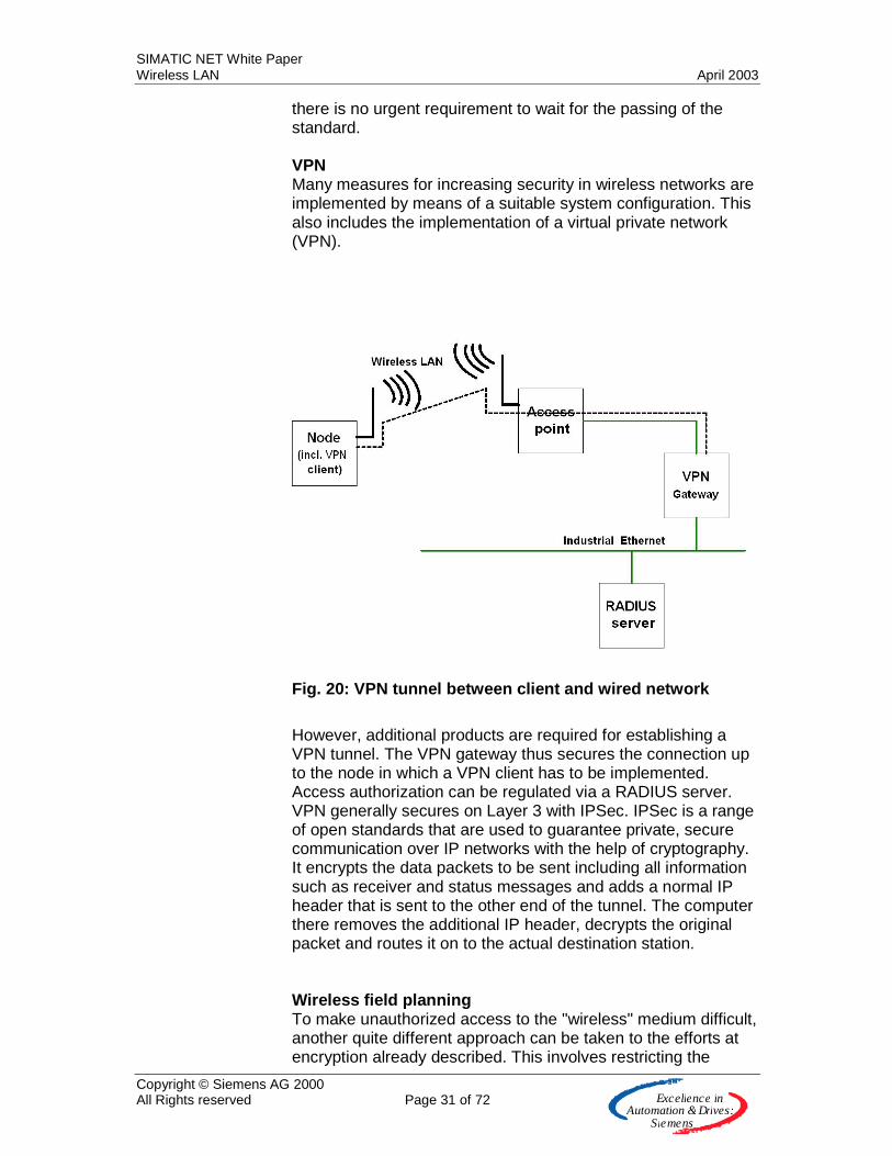
there is no urgent requirement to wait for the passing of the standard. VPN Many measures for increasing security in wireless networks are implemented by means of a suitable system configuration. This also includes the implementation of a virtual private network (VPN).
Fig. 20: VPN tunnel between client and wired network
However, additional products are required for establishing a VPN tunnel. The VPN gateway thus secures the connection up to the node in which a VPN client has to be implemented. Access authorization can be regulated via a RADIUS server. VPN generally secures on Layer 3 with IPSec. IPSec is a range of open standards that are used to guarantee private, secure communication over IP networks with the help of cryptography. It encrypts the data packets to be sent including all information such as receiver and status messages and adds a normal IP header that is sent to the other end of the tunnel. The computer there removes the additional IP header, decrypts the original packet and routes it on to the actual destination station. Wireless field planning To make unauthorized access to the "wireless" medium difficult, another quite different approach can be taken to the efforts at encryption already described. This involves restricting the
SIMATIC NET White Paper Wireless LAN April 2003
Copyright © Siemens AG 2000 All Rights reserved Page 32 of 72 E x c e lle n c e in
A u to m a tio n &Driv e s :S ie m e n s
expansion in radio waves and achieving controlled propagation of transmitter output. Because if antennas are selected on the basis of "more is more" when planning a system, there is a risk of "overshooting the target" and broadcasting data over an unnecessarily wide area Although the directional antenna of an attacker no longer finds those narrow-band performance peaks of other transmission procedures because IEEE 802.11b's DSSS (Direct Sequence Spread Spectrum) procedure reduces the transmitter power below the noise level, nevertheless all coding procedures are well known and standardized. In principle, therefore, an 802.11b terminal device can detect any of these transmitters, but locating the transmitter and aligning a directional antenna are more difficult. In the 2.4GHz range, wave propagation is strongly influenced by reflection, diffraction, and multipath propagation. Added to this is the fact that the physical surroundings in a room or plant are not constant and even a moved flower tub or the daily changes to pallet contents in a warehouse exercise a strong dynamic influence on coverage. This does not necessarily imply deterioration. If the waves were strongly absorbed by the stored goods on the previous day, other packaging materials or metal contents could significantly favor propagation the next day; to such an extent that our attacker, just outside the plant in the company car park with his or her sensitive antenna, could suddenly pick up a valuable stream of data. Careful planning of the wireless field is indispensable here, supplementing an approach in accordance with empirical rules. It is necessary here to model the building's features and fittings as accurately as possible. Also required is a precise description of machinery and equipment, something that is not always easy in practice. A simulation using this information can detect potential hazards and analyze optimal locations for the access points and antennas. In the subsequent verification of the simulated results, the theory is checked with the measurement of the actual transmitter power. The result is then available in black and white, complete with protocol, and has not just been conjured out of thin air. Sound planning of the wireless field also significantly boosts the availability of a network and allows improved calculation of the risk of a total crash – an extremely useful by-product. Siemens offers services for carrying out the necessary measures here. Security in the industrial environment: requirement analysis Security cannot be restricted to the data network alone. Because security is an integral component of all corporate processes and must be subject to a continuous process of improvement resulting in an individualized security policy.
SIMATIC NET White Paper Wireless LAN April 2003
Copyright © Siemens AG 2000 All Rights reserved Page 33 of 72 E x c e lle n c e in
A u to m a tio n &Driv e s :S ie m e n s
Within the scope of a security policy, a company has to define a comprehensive security concept. Here, all corporate processes are evaluated and requirement analysis defines the points where special protection is necessary. Furthermore, legal requirements must be met, for example where individually set product parameters are transmitted from the production line and then stored for warranty purposes. The pharmaceutical industry is another example where sector-specific safety conditions must be observed when transferring recipes for producing medicines. Requirement analysis does not, however, concentrate on the network infrastructure used but on the possible threat to processes, such as
• Spying on production data ("man in the middle", or "weak" password allocation, e.g. one password for many users)
• Damage to machinery through intentionally caused overload situations on the network ("denial of service")
• Production failure through interference with production rates with diagnostics services to the network administration (e.g. SNMP calls)
• Damage to plants through operator error Risk analysis Once the relevant processes have been found, the risk of a fault must be calculated and evaluated. The risk incorporates the two parameters frequency and extent of damage. The extent of the damage caused by a fault can be specified right down to the last euro and cent because a plant standstill immediately results in production failure and loss of sales. By contrast, the frequency of such a fault can only be calculated when empirical values are already available, something that cannot be expected in the case of a newly installed WLAN infrastructure. Since access to wireless networks is not restricted to one location, a higher probability of unauthorized access must be expected. The company car park is only one of the potential locations for hacking the network, if the attacker is armed with a sensitive antenna and the knowledge of where an access point is located. Added to this outside threat is the possibility of attack from within the company's premises.
SIMATIC NET White Paper Wireless LAN April 2003
Copyright © Siemens AG 2000 All Rights reserved Page 34 of 72 E x c e lle n c e in
A u to m a tio n &Driv e s :S ie m e n s
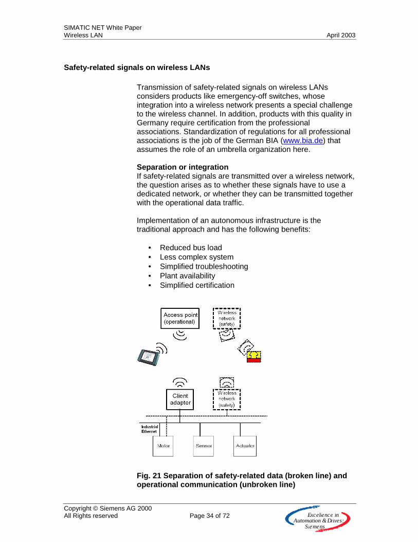
Safety-related signals on wireless LANs Transmission of safety-related signals on wireless LANs considers products like emergency-off switches, whose integration into a wireless network presents a special challenge to the wireless channel. In addition, products with this quality in Germany require certification from the professional associations. Standardization of regulations for all professional associations is the job of the German BIA (www.bia.de) that assumes the role of an umbrella organization here. Separation or integration If safety-related signals are transmitted over a wireless network, the question arises as to whether these signals have to use a dedicated network, or whether they can be transmitted together with the operational data traffic. Implementation of an autonomous infrastructure is the traditional approach and has the following benefits:
• Reduced bus load • Less complex system • Simplified troubleshooting • Plant availability • Simplified certification
Fig. 21 Separation of safety-related data (broken line) and operational communication (unbroken line)

SIMATIC NET White Paper Wireless LAN April 2003
Copyright © Siemens AG 2000 All Rights reserved Page 35 of 72 E x c e lle n c e in
A u to m a tio n &Driv e s :S ie m e n s
The advantage of a separate network is reduced complexity but this can also be implemented with an integrated concept. Customer benefits enter new dimensions if a wireless network is improved in such as way that it can transfer safety-related signals in addition to operational data.
• Reduction of the planning and configuring overhead • Reduction in installation and commissioning costs • Standardized operation • Reduced overhead for infrastructure • Greater flexibility
Fig. 22 Safety-related data (broken line) and operational communication (unbroken line) in a network
An integrated wireless network is, of course, an enormous challenge in terms of technical implementation, and also requires improvement to Industrial Ethernet (Safety on Industrial Ethernet). The great benefit derives from standardized communications handling, resulting in significantly reduced life cycle costs. Safety standards The standards EN 1050 and EN 292 are among those that analyze the risk potential of a plant. Taking account of the established risk, EN 954-1 then describes the basic design principles for safety-related controller sections and breaks these
SIMATIC NET White Paper Wireless LAN April 2003
Copyright © Siemens AG 2000 All Rights reserved Page 36 of 72 E x c e lle n c e in
A u to m a tio n &Driv e s :S ie m e n s
down into different categories. This subdivision ranges from the simplest Category B right up to the high-grade Category 4. By contrast, DIN V 19250 considers the safety of MSR protection equipment. Such equipment is also classified in different stages from AK1 to AK8 taking account of the established risk. By contrast, DIN 19251 supplies requirements and measures for safe functioning according to class. DIN V VDE 0801 and the amendment A1 are also to be observed here. They define the basic principles for computers in systems with safety tasks. Since "computer" is used in the general sense here, this standard also applies to microcontroller systems. IEC 61508 IEC 61508 is a relatively new standard. It takes account of the functional safety of electrical, electronic, and programmable electronic safety systems and arranges them into "Safety Integrity Levels" from SIL 1 to SIL 4. It takes account of the still valid standards DIN V 19251 and DIN V VDE 0801. The generally valid standards for electrical safety such as EN 60204-1 or DIN VDE 0110, the European Machinery Directive (98/37/EG), and the EMC standards must, of course, not be ignored. Safe wireless The development of wireless transmission mechanisms for safety-related signals opens up additional customer benefits, for example in the case of handheld programming devices for CNC machines or robots. If we examine safe communication at the application level of sender and receiver, the actual wireless transmission medium and its connection to the sender and receiver are actually of secondary significance for safety engineering. For this reason, a safe signal can also be transmitted wirelessly using a correspondingly safe protocol (gray channel). The modified bit error probabilities must of course be integrated into the analysis of the residual error probability for the transmission.
Biological tolerability of wireless networks The question of whether electromagnetic fields constitute a danger to health – for example in conjunction with (high-frequency) mobile wireless or (low-frequency) high-voltage power lines – is taken seriously in the area of Automation and drives and by Siemens. Protection of the population, customers, and employees is extremely important and takes priority over economic interests. The products are subject to and comply with currently valid limit values recommended by international committees on the basis
SIMATIC NET White Paper Wireless LAN April 2003
Copyright © Siemens AG 2000 All Rights reserved Page 37 of 72 E x c e lle n c e in
A u to m a tio n &Driv e s :S ie m e n s
of numerous scientific studies. These limit values are well below the field strengths above which health-related effects would occur. In the opinion of independent scientific committees and in the light of current knowledge, no damage to health will result provided these limit values are maintained. This assessment was reconfirmed by the German Radiation Protection Commission (SSK, www.bfs.de) in September 2001 following careful analysis of the latest scientific knowledge. Another detailed study commissioned by the German Association of Electrical Engineers (VDE) (http://www.vde.de/vde/html/d/aktuelles/mobilgesund.htm) reached the conclusion in March 2002 that "no danger to health from mobile wireless systems" can be proved As well as strictly complying with the limit values, Siemens also carefully analyzes new scientific developments and insights. In addition, Siemens also promotes independent scientific research into the effects of electromagnetic fields. In the EU, wireless equipment for wireless LANs come under the jurisdiction of the R&TTE Directive. In Germany, this directive is implemented by the legislation on wireless equipment and telecommunications terminal equipment (FTEG). Part of this directive covers "the protection of the health and safety of the user and any other person". It requires product manufacturers to arrange for the one-off appraisal of their products by the competent authorities. Today's wireless LAN systems are significantly below the required limit values. The maximum transmitter power of a wireless LAN system, for example, is 0.1W, while the transmitter power of a commercially available cell phone is around 2W. According to the German Federal Office for Radiation Protection, the emission from a microwave oven is around 5mW/cm², significantly higher for the overall device, therefore, than the emission power of a wireless LAN system. The following points can be helpful when dealing with wireless LAN products:
• Restriction of the exposition (effect of high-frequency electromagnetic fields according to time and quantity) to a necessary minimum
• Regular information and elucidation concerning the latest
state of the art, available in the relevant literature and from Siemens A&D
SIMATIC NET White Paper Wireless LAN April 2003
Copyright © Siemens AG 2000 All Rights reserved Page 38 of 72 E x c e lle n c e in
A u to m a tio n &Driv e s :S ie m e n s
• Particular consideration for vulnerable persons such as children and teenagers
• Particular consideration for persons with pacemakers
and hearing aids.
• Observance of the minimum distance of 0.5 m between antennas and personnel wherever possible. This does not mean that a reduction of this distance represents a health hazard.
SIMATIC NET White Paper Wireless LAN April 2003
Copyright © Siemens AG 2000 All Rights reserved Page 39 of 72 E x c e lle n c e in
A u to m a tio n &Driv e s :S ie m e n s
Official approval We differentiate between two basic groups in product approval. The Wireless Ethernet Compatibility Alliance (WECA) has been established for some time to guarantee the interoperability of IEEE 802.11 components from different manufacturers. On passing the compatibility test, the products are entitled to carry the Wi-Fi (Wireless Fidelity) seal. A requirement for carrying the seal is, of course, that the products comply with the relevant IEEE standard. However, neither IEEE nor Wi-Fi has any legal relevance for approval by the national regulating bodies. In many countries, the competent bodies (in Germany the RegTP) must approve the manufacturer's complete product (including antenna) once. In doing so, a check is made that the prescribed, band-specific transmitter power is not exceeded (not more than 100mW in the 2.4GHz band). Operation of these wireless devices then requires no further approval. In Germany, however, operation beyond the boundaries of premises must be registered but is not subject to any fee following approval. So in the case of interference between two neighboring applications the first one to register can continue system operation unchanged. Transmission power, EIRP The transmitter power radiated by a WLAN system is restricted in the ISM band by the certification authorities. In Europe, 100mW transmitter power is permissible. This specification often leads to confusion because in Europe it refers to the entire setup including antennas. The US literature often contains a corresponding rating, but this refers only to the wireless module and does not take account of gain resulting from skilled design of the antenna (passive gain!). In Europe, the maximum permissible equivalent isotropic radiation power (EIRP) is 100mW (20dBm=10 log 100mW) in the 2.4GHz ISM band. This maximum radiation power applies both for access points and for node systems and must not be exceeded even when gain antennas are used (in order to enable fault-free operation of other wireless systems operated in the same frequency range).

SIMATIC NET White Paper Wireless LAN April 2003
Copyright © Siemens AG 2000 All Rights reserved Page 40 of 72 E x c e lle n c e in
A u to m a tio n &Driv e s :S ie m e n s
Industrial use of a wireless LAN system
Applications for wireless LANs in automation The benefit of wireless LAN technology is in the mobility of individual components and their flexible use. This mobility allows the restructuring of work processes and the implementation of innovative solutions. There are many obvious applications in automation engineering where wireless communication between individual nodes result in additional benefits for users. Customers favor wireless LANs particularly in those cases where there is a clear advantage over the use of cable.
• Communication with mobile nodes, mobile data acquisition
Using mobile, industrial Internet pads like Mobic (Mobile Industrial Communicator) from Simatic Net, users can acquire data from all production and storage areas and route them on for centralized processing. The mobile handhelds used here are no longer assigned to a machine or a process but to a user. The number of devices required is reduced significantly. In addition, the costly and error-prone process of transferring data from paper to the centralized database is no longer necessary. With an integrated concept for data acquisition, significant costs can be saved, especially at the interfaces where data is transferred from one process step to the next in the value added chain.
• Mobile service and diagnostics In the event of a fault, service personnel can analyze the problem on-site and view the information needed to quickly eliminate the fault via the Mobic wireless Web pad. The availability of spare parts in the warehouse can be immediately checked and parts ordered online if necessary. However, diagnostics are not restricted to faults. Personnel can diagnose operational data such as levels or machine capacities quickly and securely.
SIMATIC NET White Paper Wireless LAN April 2003
Copyright © Siemens AG 2000 All Rights reserved Page 41 of 72 E x c e lle n c e in
A u to m a tio n &Driv e s :S ie m e n s
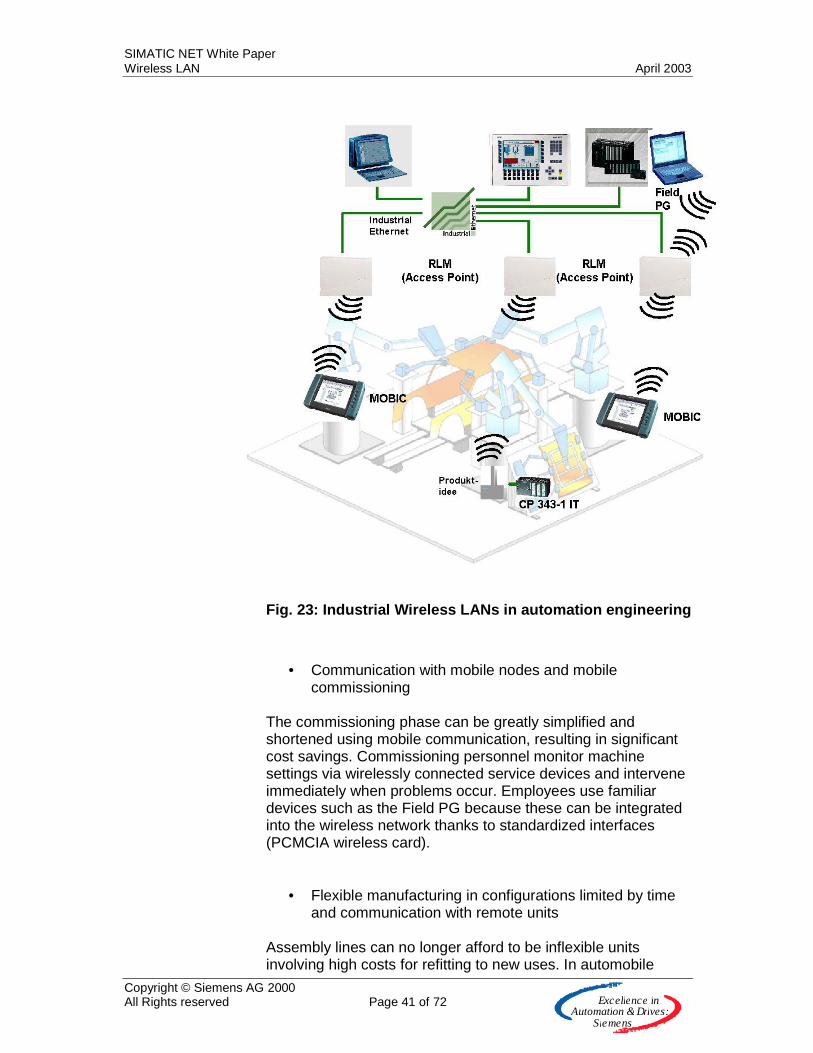
Fig. 23: Industrial Wireless LANs in automation engineering
• Communication with mobile nodes and mobile commissioning
The commissioning phase can be greatly simplified and shortened using mobile communication, resulting in significant cost savings. Commissioning personnel monitor machine settings via wirelessly connected service devices and intervene immediately when problems occur. Employees use familiar devices such as the Field PG because these can be integrated into the wireless network thanks to standardized interfaces (PCMCIA wireless card).
• Flexible manufacturing in configurations limited by time and communication with remote units
Assembly lines can no longer afford to be inflexible units involving high costs for refitting to new uses. In automobile

SIMATIC NET White Paper Wireless LAN April 2003
Copyright © Siemens AG 2000 All Rights reserved Page 42 of 72 E x c e lle n c e in
A u to m a tio n &Driv e s :S ie m e n s
manufacture in particular, factory layouts are subject to fast changeovers. Flexible manufacturing makes it possible to implement customer desires quickly and without long refitting times. Thanks to wireless data networking, production units are integrated into the data network quickly and without any great connection overhead. In addition, test installations can be implemented quickly and without undue overhead. A wireless LAN also allows low-cost connection of distant machines and controllers installed in locations that are extremely difficult to access. This avoids costly cabling. Please note: Wireless systems have the advantage over cabled systems only where
��an existing cable duct cannot be used (e.g. data and power must not be run together)
��a new cable duct would have to be installed ��data have to be routed across public highways
• Communication with mobile nodes Connection of mobile devices to the data network involves significant overhead. In the case of electric suspension monorails (ESMs), wireless connection saves on data routing along the tracks, and in driverless transport system it is no longer necessary to use contamination-prone optical systems. In addition, the routes in both applications can be easily modified, resulting in great flexibility. Integration of rotating devices into a data network avoids wear-and-tear on the slip rings. The same benefit also applies when replacing drag chains.
Examples Local service and diagnostics on company premises Application The company occupies an extensive area (10m to several 100m), primarily indoors but with some outdoor areas. Environmental conditions often require a higher degree of protection for products not installed in control cabinets. The machines to be monitored are part of an extensive manufacturing or process plant and are strongly dependent on each other so that the result of one machine can influence the operation of another. A communications network (such as Ethernet) is installed for data exchange from the control level to the field level.

SIMATIC NET White Paper Wireless LAN April 2003
Copyright © Siemens AG 2000 All Rights reserved Page 43 of 72 E x c e lle n c e in
A u to m a tio n &Driv e s :S ie m e n s
For local service (on-site fault elimination, program upload, data download, firmware update, commissioning, configuring), access to the process must be monitored locally. This is done using a mobile device with an effective area of a few meters. For diagnostics (process visualization, monitoring of operational data), the process doesn't have to be monitored locally so the effective area of a mobile device can be between a few meters and several hundred 100 meters.
Fig. 24: Mobic in manufacturing automation and for service purposes
Solution For a high level of customer benefit, not only must the wireless network enable service work in the local environment (a few meters) but it must also be possible to carry out diagnostics functions within an extensive effective area. The data rate must be sufficient for diagnostics purposes or visualization of process data since complex data are also visualized. For this reason, a device with a large display (laptop, Internet Pad) is assumed for diagnostics. For these two reasons (range and data rate), use of a wireless LAN is to be recommended in this application. In addition, the roaming function standardized in WLAN supports seamless use across large areas since data is transmitted without interrupt from one access point to the next. The costs for installing a wireless network, and the acquisition costs for mobile terminal devices, are spread across the
SIMATIC NET White Paper Wireless LAN April 2003
Copyright © Siemens AG 2000 All Rights reserved Page 44 of 72 E x c e lle n c e in
A u to m a tio n &Driv e s :S ie m e n s
company's premises over many machines on the data network that can be diagnosed. Data exchange between a remote controller and a data network on the company's premises. Application An exchange of information takes place between a remote controller or a machine and the wired data network (e.g. Ethernet) on the company's premises over maximum distances of several hundred meters. Connection to the data network is not only using cable because either there are no cable ducts available or the data cable cannot be laid in the available duct. Quickly changing factory layouts or frequent installation of test installations increase the advantages of establishing a wireless network. Not only operational data are transferred over the wireless network but also interrupt messages or maintenance requests. Both the remote unit and the wired data network require a wireless interface. Solution With this application, secure data transfer is required over a distance normally significantly over 10 m but not exceeding several hundred meters on the company's premises. The wireless network must be impervious to interference and reflections in the industrial environment. In addition, the net data rate for the short data packets that are the norm in the communications protocols found in automation engineering must not be too low. For these two reasons (range and data rate), use of a wireless LAN is to be recommended in this application. The comparatively high data rate offers the facility for using mobile handhelds within this wireless network, thus reducing the proportionate infrastructure costs for the remote controller. The infrastructure costs for a wireless network are particularly significant when only a single remote controller is connected. In this case, the customer benefits compared with a wired network must be assessed. Conveyor systems Application In logistics and materials management, vehicles are used today that can get around without a driver. They are moved either along an induction loop in the floor (driverless transport system) or along a guide rail above the goods to be transported (electric suspension monorail). The data are transferred either
SIMATIC NET White Paper Wireless LAN April 2003
Copyright © Siemens AG 2000 All Rights reserved Page 45 of 72 E x c e lle n c e in
A u to m a tio n &Driv e s :S ie m e n s
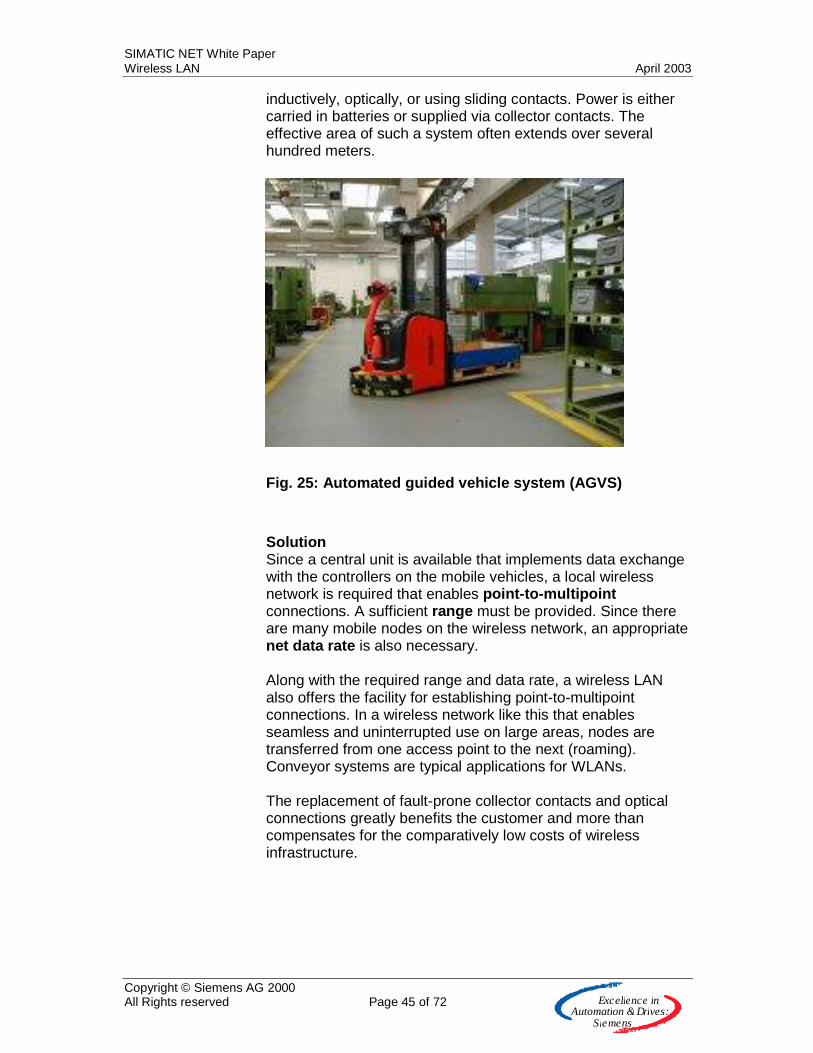
inductively, optically, or using sliding contacts. Power is either carried in batteries or supplied via collector contacts. The effective area of such a system often extends over several hundred meters.
Fig. 25: Automated guided vehicle system (AGVS)
Solution Since a central unit is available that implements data exchange with the controllers on the mobile vehicles, a local wireless network is required that enables point-to-multipoint connections. A sufficient range must be provided. Since there are many mobile nodes on the wireless network, an appropriate net data rate is also necessary. Along with the required range and data rate, a wireless LAN also offers the facility for establishing point-to-multipoint connections. In a wireless network like this that enables seamless and uninterrupted use on large areas, nodes are transferred from one access point to the next (roaming). Conveyor systems are typical applications for WLANs. The replacement of fault-prone collector contacts and optical connections greatly benefits the customer and more than compensates for the comparatively low costs of wireless infrastructure.
SIMATIC NET White Paper Wireless LAN April 2003
Copyright © Siemens AG 2000 All Rights reserved Page 46 of 72 E x c e lle n c e in
A u to m a tio n &Driv e s :S ie m e n s
Linking data networks from building to building (B2B) Application Connecting the data networks of 2 buildings can involve considerable difficulties if, for example, public areas or highways (or rail tracks) have to be bridged. However, customers can also benefit from a wireless link if the connection is only temporary or is to serve test purposes. Solution This application underlines the benefits of WLANs by highlighting range and data rate. At the same time, it is one of the oldest applications for this technology. The demand for outdoor application requires only the antennas used if the wireless module is installed inside the building and connected to the antenna using an antenna cable run through a hole drilled in the external wall of the building.
SIMATIC NET White Paper Wireless LAN April 2003
Copyright © Siemens AG 2000 All Rights reserved Page 47 of 72 E x c e lle n c e in
A u to m a tio n &Driv e s :S ie m e n s
Wireless LAN products from Simatic Net In the office area, wireless LAN technology is already widely used, with the greatest growth forecast for SOHO (Small Office/ Home Office) and Consumer. In order to be able to use wireless communications technology in the industrial area too, we recommend the use of products specially designed for these areas. In the industrial area, there are many factors that could unfavorably influence wireless connection. These include machine and warehouse units that shield radio waves due to their metallic design. The wireless system is also continuously modified by the effect of moving personnel and transport vehicles. Industrial manufacturing sites are usually in large halls in which the effects of multipath propagation are especially significant. This makes it impossible to guarantee constant marginal conditions for wireless transmission. For the use of wireless LAN technology in the industrial area, Simatic Net offers products that guarantee secure data transmission in spite of the demanding environmental conditions. In order to avoid the increasing prevalence of multipath propagation in assembly halls (see Fig. 2: Multipath propagation of radio waves) and the resulting effects of attenuation or destruction of radio waves, the wireless modules are equipped with two antennas (antenna diversity). The receiver is thus able to select the stronger of two received signals. To guarantee secure data transmission, the modules must be able to switch back to a lower data rate from the highest data rate under conditions where the quality of the transmission path is constantly changing (number of nodes, changing distance of the nodes to the access point). The design of the products must also meet the requirements of harsh industrial environments and enable simple installation. In addition, the modules must provide the user-friendliness of an IT component such as Web-based management with SNMP or the sending of e-mails or SMS messages. SIMATIC Net offers two products for establishing a wireless industrial network:
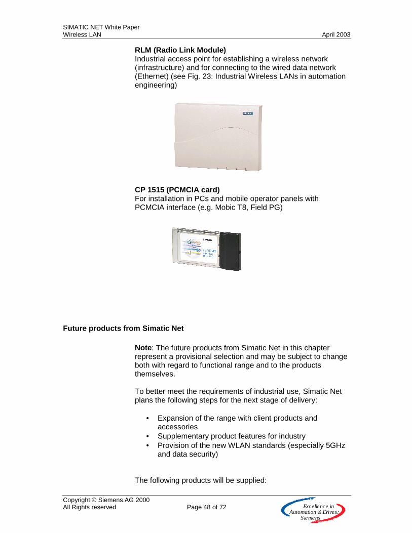
SIMATIC NET White Paper Wireless LAN April 2003
Copyright © Siemens AG 2000 All Rights reserved Page 48 of 72 E x c e lle n c e in
A u to m a tio n &Driv e s :S ie m e n s
RLM (Radio Link Module) Industrial access point for establishing a wireless network (infrastructure) and for connecting to the wired data network (Ethernet) (see Fig. 23: Industrial Wireless LANs in automation engineering) CP 1515 (PCMCIA card) For installation in PCs and mobile operator panels with PCMCIA interface (e.g. Mobic T8, Field PG)
Future products from Simatic Net Note: The future products from Simatic Net in this chapter represent a provisional selection and may be subject to change both with regard to functional range and to the products themselves. To better meet the requirements of industrial use, Simatic Net plans the following steps for the next stage of delivery:
• Expansion of the range with client products and accessories
• Supplementary product features for industry • Provision of the new WLAN standards (especially 5GHz
and data security) The following products will be supplied:
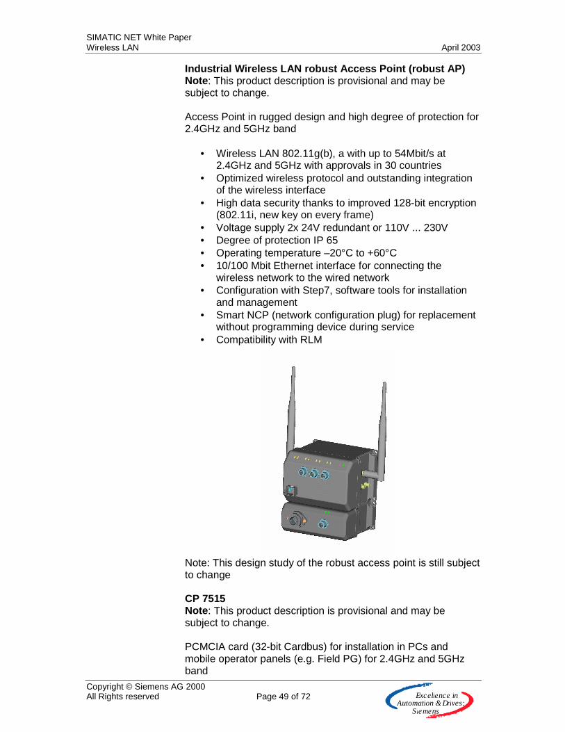
SIMATIC NET White Paper Wireless LAN April 2003
Copyright © Siemens AG 2000 All Rights reserved Page 49 of 72 E x c e lle n c e in
A u to m a tio n &Driv e s :S ie m e n s
Industrial Wireless LAN robust Access Point (robust AP) Note: This product description is provisional and may be subject to change. Access Point in rugged design and high degree of protection for 2.4GHz and 5GHz band
• Wireless LAN 802.11g(b), a with up to 54Mbit/s at 2.4GHz and 5GHz with approvals in 30 countries
• Optimized wireless protocol and outstanding integration of the wireless interface
• High data security thanks to improved 128-bit encryption (802.11i, new key on every frame)
• Voltage supply 2x 24V redundant or 110V ... 230V • Degree of protection IP 65 • Operating temperature –20°C to +60°C • 10/100 Mbit Ethernet interface for connecting the
wireless network to the wired network • Configuration with Step7, software tools for installation
and management • Smart NCP (network configuration plug) for replacement
without programming device during service • Compatibility with RLM
Note: This design study of the robust access point is still subject to change CP 7515 Note: This product description is provisional and may be subject to change. PCMCIA card (32-bit Cardbus) for installation in PCs and mobile operator panels (e.g. Field PG) for 2.4GHz and 5GHz band
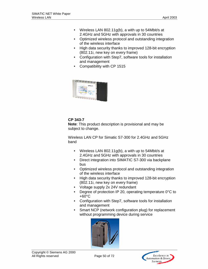
SIMATIC NET White Paper Wireless LAN April 2003
Copyright © Siemens AG 2000 All Rights reserved Page 50 of 72 E x c e lle n c e in
A u to m a tio n &Driv e s :S ie m e n s
• Wireless LAN 802.11g(b), a with up to 54Mbit/s at
2.4GHz and 5GHz with approvals in 30 countries • Optimized wireless protocol and outstanding integration
of the wireless interface • High data security thanks to improved 128-bit encryption
(802.11i, new key on every frame) • Configuration with Step7, software tools for installation
and management • Compatibility with CP 1515
CP 343-7 Note: This product description is provisional and may be subject to change. Wireless LAN CP for Simatic S7-300 for 2.4GHz and 5GHz band
• Wireless LAN 802.11g(b), a with up to 54Mbit/s at 2.4GHz and 5GHz with approvals in 30 countries
• Direct integration into SIMATIC S7-300 via backplane bus
• Optimized wireless protocol and outstanding integration of the wireless interface
• High data security thanks to improved 128-bit encryption (802.11i, new key on every frame)
• Voltage supply 2x 24V redundant • Degree of protection IP 20, operating temperature 0°C to
+60°C • Configuration with Step7, software tools for installation
and management • Smart NCP (network configuration plug) for replacement
without programming device during service
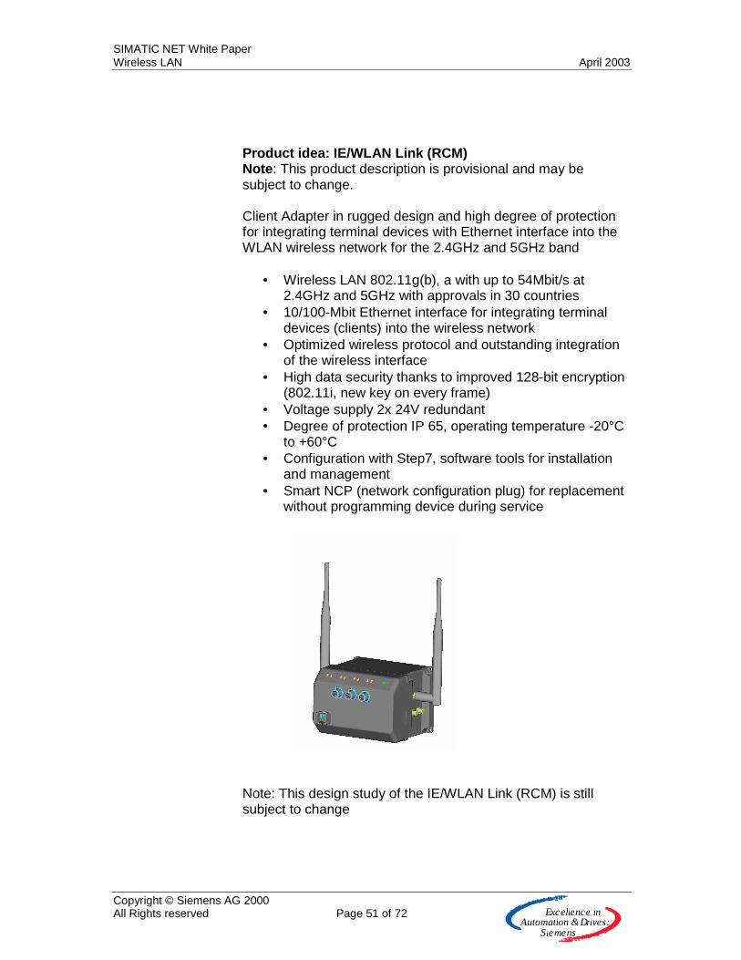
SIMATIC NET White Paper Wireless LAN April 2003
Copyright © Siemens AG 2000 All Rights reserved Page 51 of 72 E x c e lle n c e in
A u to m a tio n &Driv e s :S ie m e n s
Product idea: IE/WLAN Link (RCM) Note: This product description is provisional and may be subject to change. Client Adapter in rugged design and high degree of protection for integrating terminal devices with Ethernet interface into the WLAN wireless network for the 2.4GHz and 5GHz band
• Wireless LAN 802.11g(b), a with up to 54Mbit/s at 2.4GHz and 5GHz with approvals in 30 countries
• 10/100-Mbit Ethernet interface for integrating terminal devices (clients) into the wireless network
• Optimized wireless protocol and outstanding integration of the wireless interface
• High data security thanks to improved 128-bit encryption (802.11i, new key on every frame)
• Voltage supply 2x 24V redundant • Degree of protection IP 65, operating temperature -20°C
to +60°C • Configuration with Step7, software tools for installation
and management • Smart NCP (network configuration plug) for replacement
without programming device during service
Note: This design study of the IE/WLAN Link (RCM) is still subject to change
SIMATIC NET White Paper Wireless LAN April 2003
Copyright © Siemens AG 2000 All Rights reserved Page 52 of 72 E x c e lle n c e in
A u to m a tio n &Driv e s :S ie m e n s
Antennas Note: The product description and range of functions represent provisional specifications and may be subject to change.
• Omni-directional antenna for 2.4GHz and 5GHz for expanding and optimizing the wireless connection (IWLAN robust Access Point, CP 343-7)
• Planar antenna (180°) for 2.4GHz and 5GHz for expanding and optimizing the wireless connection (IWLAN robust Access Point, CP 343-7)
• Directional antenna (60°) for 2.4GHz and 5GHz for expanding and optimizing the wireless connection (IWLAN robust Access Point, CP 343-7)
• Vehicle antenna (omni-directional) for 2.4GHz and 5GHz for expanding and optimizing the wireless connection, especially for driverless transport systems (CP 343-7)
Antenna cable (prepared with connector and socket) Note: The product description and range of functions represent provisional specifications and may be subject to change.
• Length 2m • Length 5m • Length 10m
Lightning protection element Note: The product description and range of functions represent provisional specifications and may be subject to change. For connecting remote antennas in the outdoor area Connectors and adapters Note: The product description and range of functions represent provisional specifications and may be subject to change. For optimally coordinated connection of the antennas, antenna cables, and lightning protection element offered.

SIMATIC NET White Paper Wireless LAN April 2003
Copyright © Siemens AG 2000 All Rights reserved Page 53 of 72 E x c e lle n c e in
A u to m a tio n &Driv e s :S ie m e n s
Other wireless technologies
Bluetooth
Bluetooth is the result of developments by the Telecom vendors Nokia and Ericsson and was developed for the communication of mobile devices with each other (establishment of personal area networks, PANs). Standardization is handled in the SIG (Special Interest Group, www.bluetooth.com ), with a current membership of 3,500 companies. The name "Wireless RS 232" is often connected with Bluetooth. This puts the focus on replacing cable, with the advantages of mobility coming to fruition. Today, the most important application is the mobile phone, where Bluetooth implements a wireless connection between the headset (headphone and microphone) and the mobile phone.
Fig. 26: Bluetooth headset
Printers and PDAs are also equipped with Bluetooth This clearly indicates the strengths: low component costs and minimum current consumption at short ranges that are sufficient for this application. If voice transmission is required, Bluetooth has special advantages thanks to the detailed specification in the standard.
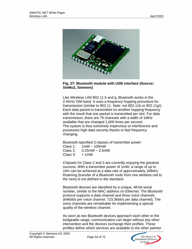
SIMATIC NET White Paper Wireless LAN April 2003
Copyright © Siemens AG 2000 All Rights reserved Page 54 of 72 E x c e lle n c e in
A u to m a tio n &Driv e s :S ie m e n s
Fig. 27: Bluetooth module with USB interface (Source: SieMo2, Siemens)
Like Wireless LAN 802.11 b and g, Bluetooth works in the 2.4GHz ISM band. It uses a frequency hopping procedure for transmission (similar to 802.11. Note: not 802.11b or 802.11g!). Each data packet is transmitted on another hopping frequency with the result that one packet is transmitted per slot. For data transmission, there are 79 channels with a width of 1MHz available that are changed 1,600 times per second. The system is thus extremely impervious to interference and possesses high data security thanks to fast frequency changing. Bluetooth specified 3 classes of transmitter power: Class 1: 1mW – 100mW Class 2: 0.25mW – 2.5mW Class 3: < 1mW Chipsets for Class 2 and 3 are currently enjoying the greatest success. With a transmitter power of 1mW, a range of up to 10m can be achieved at a data rate of approximately 1Mbit/s. Roaming (transfer of a Bluetooth node from one wireless cell to the next) is not defined in the standard. Bluetooth devices are identified by a unique, 48-bit serial number, similar to the MAC address on Ethernet. The Bluetooth protocol supports a data channel and three voice channels (64kbit/s per voice channel, 723.3kbit/s per data channel). The voice channels are remarkable for implementing a special quality of the wireless channel. As soon as two Bluetooth devices approach each other to the bridgeable range, communication can begin without any other intervention and the devices exchange their profiles. These profiles define which services are available to the other partner.
SIMATIC NET White Paper Wireless LAN April 2003
Copyright © Siemens AG 2000 All Rights reserved Page 55 of 72 E x c e lle n c e in
A u to m a tio n &Driv e s :S ie m e n s
Different profiles can be implemented depending on the performance of the client. There are, for example, profiles for printers or mobile telephones. (This is precisely the point at which slight incompatibilities have appeared in the past between different manufacturers, making joint operation of different products difficult.) The resulting structure is known as a piconet. Up to eight nodes can be integrated into a piconet, within which a Bluetooth node assumes the role of the master. If more than eight devices communicate with each other, several, partly overlapping, piconets are formed. This network structure is known as a scatternet. Data protection is a high priority with Bluetooth because e-commerce applications were an early focus. Using the Bluetooth address and a random number generator, the master of a piconet generates a key that defines the hopping sequence in the pico cell. This sequence must be used by all piconet nodes. The random number generator generates a new hopping sequence at each new connection buildup. In addition to the constantly changing frequency bands, the transmitted data are encoded with a 128-bit key. The length of this key can be reduced for small, low-performance terminal devices. To improve the compatibility of devices from different manufacturers, each new device must be tested and certified by an independent institute (Bluetooth Qualification Test Facility, BQTF). Bluetooth is therefore also of interest for industrial applications requiring point-to-point connections, if range, roaming, and a high data rate are not important. Interference between Bluetooth and WLAN Because data is transmitted in the same frequency band at 2.4GHz, interference can occur. It must be noted, however, that interference is only relevant when the different wireless modules are operated in close proximity to each other. The actual effect on the wireless connections is strongly contended. Bluetooth is certainly more impervious since the transmitting frequency is changed very quickly so interference only affects one slot. Bluetooth generally transmits with only 1mW in comparison with the nth power of a WLAN transmitter. The SIG is currently working with a new version of the standard where Bluetooth omits the transmitter frequencies of a WLAN transmitter when this is "discovered". This mechanism significantly increases the compatibility of the technologies and further reduces the problems.
SIMATIC NET White Paper Wireless LAN April 2003
Copyright © Siemens AG 2000 All Rights reserved Page 56 of 72 E x c e lle n c e in
A u to m a tio n &Driv e s :S ie m e n s
DECT
DECT (Digital Enhanced Cordless Telecommunications) is a widely used standard for wireless voice transmission. The terminal devices are primarily cordless telephones. However, data services such as fax or multimedia can also be implemented with this connection-oriented wireless technology. DECT has been standardized by ETSI since 1992 in over 100 countries but not in the US. This extraordinarily successful technology reached over 100 million installations by 2001. DECT works in the frequency range 1.88GHz to 1.939GHz. For operation in the US, a version with frequency hopping was specified that works in the license-free ISM band at 2.4GHz. In Europe, 3 sub-bands have been defined at 1.88GHz with 10 carrier frequencies each that have a width of 2MHz. These are further subdivided with TDMS (Time Division Multiplex) into 24 time slices with a period duration of 10ms. 12 of these time slices are reserved for the connection between the base station and the mobile section (downlink) for 5ms and 12 are reserved in the other direction (uplink) for 5ms. This means 120 connections can be implemented in one wireless cell with no overlap. At 24kbit/s per TDMS time slice, between 567kbit/s und 3.456Mbit/s can be transmitted if all time slices are bundled. An important restriction with DECT is the availability of the 1.9GHz frequency band in America. To provide a solution here, DECT is also offered in the 2.4GHz ISM band. DECT's success would appear to be outdone by the market entry of Bluetooth (voice) and WLAN (fast data rates). Nevertheless, the large installed base of DECT wireless networks guarantees this technology a long shelf life.
HiperLAN2
With HiperLAN/2 (High Performance Radio Local Area Network type 2), ETSI (www.etsi.org) has defined its own wireless LAN standard, providing the European counterpart to IEEE 802.11a, with the physical (PHY) section being almost identical. As well as the classical applications of wireless LANs, HiperLAN additionally addresses the question of an access technology to the UMTS 3rd generation (3G) wireless networks. (Note: ETSI specified UMTS, GSM and DECT in addition to HiperLAN).
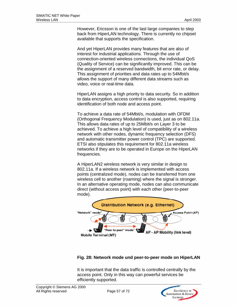
SIMATIC NET White Paper Wireless LAN April 2003
Copyright © Siemens AG 2000 All Rights reserved Page 57 of 72 E x c e lle n c e in
A u to m a tio n &Driv e s :S ie m e n s
However, Ericsson is one of the last large companies to step back from HiperLAN technology. There is currently no chipset available that supports the specification. And yet HiperLAN provides many features that are also of interest for industrial applications. Through the use of connection-oriented wireless connections, the individual QoS (Quality of Service) can be significantly improved. This can be the assignment of a reserved bandwidth, bit error rate, or delay. This assignment of priorities and data rates up to 54Mbit/s allows the support of many different data streams such as video, voice or real-time data. HiperLAN assigns a high priority to data security. So in addition to data encryption, access control is also supported, requiring identification of both node and access point. To achieve a data rate of 54Mbit/s, modulation with OFDM (Orthogonal Frequency Modulation) is used, just as on 802.11a. This allows data rates of up to 25Mbit/s on Layer 3 to be achieved. To achieve a high level of compatibility of a wireless network with other nodes, dynamic frequency selection (DFS) and automatic transmitter power control (TPC) are supported. ETSI also stipulates this requirement for 802.11a wireless networks if they are to be operated in Europe on the HiperLAN frequencies. A HiperLAN2 wireless network is very similar in design to 802.11a. If a wireless network is implemented with access points (centralized mode), nodes can be transferred from one wireless cell to another (roaming) where the signal is stronger. In an alternative operating mode, nodes can also communicate direct (without access point) with each other (peer-to-peer mode).
Fig. 28: Network mode und peer-to-peer mode on HiperLAN
It is important that the data traffic is controlled centrally by the access point. Only in this way can powerful services be efficiently supported.
SIMATIC NET White Paper Wireless LAN April 2003
Copyright © Siemens AG 2000 All Rights reserved Page 58 of 72 E x c e lle n c e in
A u to m a tio n &Driv e s :S ie m e n s
Home RF
HomeRF has been standardized by the Home Radio Frequency Working Group (HomeRF WG) (www.homerf.org) originally comprising Compaq, Hewlett-Packard, IBM, Intel and Microsoft. The group was established in 1998 to promote the interoperability of products. In the fall of 2001, a European branch was opened with the aim of more aggressively introducing the standard to the market there. HomeRF defines its target applications as being in the consumer and small office market. The aim is to wirelessly connect a variety of products simply, securely, and reliably. Four different types of networks are distinguished.
• Data networks for linking PCs • Communication networks for telephones • Entertainment networks with TV and games • Building and home automation (heating, refrigerator)
HomeRF combines two standards – IEEE 802.11 and Digital Enhanced Cordless Telecommunication (DECT) – and works with a frequency hopping technology of up to 1.6Mbit/s. In buildings, ranges of up to 30m are achieved. This is sufficient for home applications. Special value is placed on the integration of voice and data in the same wireless channel. The first products were introduced in 2000 (1.6Mbit/s). Further development under the name of HomeRF 2.0 already permitted a data rate of 10Mbit/s and was passed in 2001. HomeRF 3.0 finally supports wireless video in DVD quality and other multimedia applications at 25Mbit/s. Up-to-date information: The latest news about HomeRF concerns the dissolution of the above working group. It is not clear if this affects the American group as well as the European group. It had obviously become impossible to catch up with the market success and speed of standardization of the WLAN and Bluetooth technologies. You can find more detailed information direct on the working group's Web site.
GSM The technology of the first phase, analog mobile networks (e.g. C-Netz from German Telecom), has been replaced by

SIMATIC NET White Paper Wireless LAN April 2003
Copyright © Siemens AG 2000 All Rights reserved Page 59 of 72 E x c e lle n c e in
A u to m a tio n &Driv e s :S ie m e n s
advanced digital networks such as GSM (2G) (e.g. D1-Netz in Germany). The GSM standard is currently provided by around 400 mobile wireless network operators for 730 million customers in almost 180 countries and is thus the most successful mobile technology standard in the world to-date. GSM is expected to break the sound barrier of a billion nodes in 2003. GSM ("Global System for Mobile Communications") is a digital mobile communication system based on a European standard defined within the scope of the European Telecommunications Standards Institute (ETSI). On the European stage, the frequency range for the GSM system includes the GSM 900 (uplink: 880MHz to 915MHz, downlink 925MHz to 960MHz) and GSM 1800 (uplink: 1710MHz to 1785MHz, downlink: 1805MHz to 1880MHz) frequency band. The GSM 1900 frequency band is used primarily in North America. Terminal devices that support GSM 900 and 1800 are referred to as dual-band, and if they can also be operated in a GSM 1900 wireless network, they are called triple-band. The great difference to a wireless LAN is the fact that the GSM frequencies are licensed and are made available by the network providers for a fee. It is also of advantage that the services of these network providers are available almost globally. The GSM network was originally only interested in voice services. But data can also be transmitted over such a connection. The data rate here is only 9.6kbit/s or 14.4kbit/s. HSCSD In order to provide the customer with a faster data rate, an initial solution approach was to bundle several languages (language) channels to achieve up to 43.2kbit/s. The standard was known as High Speed Circuit Switched Data (HSCSD), with the two letters “CS” indicating the problem. A circuit-switched connection is extremely inefficient for such a service and robs a GSM base station of valuable resources. GPRS The way out of this situation was found with GPRS (General Packet Radio Service) where the information is transmitted in the form of packets. The terminal device (e.g. mobile telephone) thus does not have a complete wireless channel reserved for the entire time and instead only sends its data packets to the GSM base station when required. The theoretical upper limit for data transmission is then 171.2kbit/s. However, with the rollout of the GPRS networks, normal users only have data rates of 40 to 50kbit/s at their disposal over a large area. Packet-oriented
SIMATIC NET White Paper Wireless LAN April 2003
Copyright © Siemens AG 2000 All Rights reserved Page 60 of 72 E x c e lle n c e in
A u to m a tio n &Driv e s :S ie m e n s
data transmission with GPRS is approximately three times as efficient as connection-oriented data transmission with HSCSD, High Speed Circuit Switched Data. EDGE EDGE (Enhanced Data Rates for Global Systems for Mobile Communications Evolution) consists of a range of expansions for updating GPRS networks (data communication) and GSM networks (voice communication). This allows capacity and data throughput in general to be increased by up to three or four times. EDGE thus ensures that the available frequency range – a limited natural resource – can be used more effectively. A new modulation method enables wireless data rates of up to 384kbit/s, and with stationary use with restricted mobility even up to as much as 554kbit/s. According to present knowledge, data rates of at least 150kbit/s should be possible, increasing the performance of GPRS by two to three times. EDGE can therefore make full use of the benefits offered by GPRS. With these data rates, EDGE is a precursor of the UMTS wireless networks. This is why it is referred to as 2.5G (G: generation). It must be noted that in Germany, this standard is not offered by network operators (providers) because it is seen as a cannibalization of the introduction of UMTS (3G). EDGE is therefore of interest for mobile wireless operators that have no UMTS licenses. It offers the possibility of superimposing fast bit services as well as higher capacity with improved spectral efficiency onto the existing GSM or TDMA frequency band. For this reason, the first EDGE networks are implemented in the US.
WCDMA, UMTS The 3rd generation (3G) of mobile wireless technology enables new applications through mobile multimedia services, for example, for infotainment, but also mobile commerce (m-commerce). This addresses the mass market for telecommunications customers. In order to enable even more extensive service in future, 3G communications standards and technologies have been developed that provide data rates in excess of 384kbit/s, right up to 2Mbit/s – theoretically even up to several Mbit/s. The capacity of the networks is thus significantly increased so that large volumes of data can be transmitted wirelessly. Availability of this high speed in individual networks will depend on the services and configurations of each network operator. In the first years of availability of 3G networks, it will be possible to
SIMATIC NET White Paper Wireless LAN April 2003
Copyright © Siemens AG 2000 All Rights reserved Page 61 of 72 E x c e lle n c e in
A u to m a tio n &Driv e s :S ie m e n s
implement most networks with data rates between 128 and 384kbit/s. 3G standards Two families of standards have emerged that enable data rates over 384kbit/s: WCDMA (Wideband Code Division Multiple Access), a technology that is based on the evolution of GSM/GPRS/EDGE and makes use of its global spread, as well as CDMA2000 1xEV-DV, based on the narrow-band standard IS-95 (also called cdmaOne). As far as the licensing of 3G networks is concerned, the large majority of mobile wireless network operators have decided in favor of WCDMA as the standard of preference. To-date, over a hundred WCDMA licenses have been granted in the 3G frequency range (2.1GHz), while only two licenses have been granted for the CDMA2000 technology family. WCDMA und UMTS WCDMA uses the 2.1GHz frequency band in Europe and at other locations where this frequency is not occupied by other services. Other frequencies are used in North and South America. The WCDMA technology that uses the 2.1GHz frequency band is known in Europe generally as UMTS (Universal Mobile Telecommunications System). The key to the success of WCDMA is the comprehensive interoperability between networks and terminal devices. The interaction of dual-mode-enabled mobile telephones and GSM/WCDMA is indispensable for opening up the mass market for advanced mobile services. The UMTS wireless network will not be a further development of the GSM network but will exist alongside it. This means there will be a shared carrier network and two separate wireless networks for UMTS and GSM existing side-by-side. The UMTS wireless network will enable multimedia applications thanks to the wide bandwidth of the frequency channels (5MHz instead of 200kHz at GSM) and a new transmission method (CDMA - Code Division Multiple Access). Multimedia in UMTS means the ability to transmit voice, data, text, pictures, audio, and video with a maximum data rate of 2Mbit/s. Purely voice transmission (without multimedia) will to a grate extent continue to be handled via GSM for cost reasons. Hierarchical cell structure UMTS will have global wireless supply and it will enable roaming worldwide. For this purpose, the wireless network of UMTS (UMTS Radio Access Network - URAN) will be established hierarchically in supply levels. Each higher level in the hierarchy supplies a geographically larger area than the one below. At the highest hierarchy level, satellites will enable global supply, with the lower hierarchy levels forming the
SIMATIC NET White Paper Wireless LAN April 2003
Copyright © Siemens AG 2000 All Rights reserved Page 62 of 72 E x c e lle n c e in
A u to m a tio n &Driv e s :S ie m e n s
terrestrial wireless network (UMTS Terrestrial Radio Access Network - UTRAN). These are subdivided into macro, micro, and pico levels. Each level has a cellular structure. The lower the hierarchy level, the smaller the cell radii. Smaller cells allow a greater density of nodes. For this reason, macro cells are used for basic large area coverage, micro cells additionally in densely populated (urban) areas, and if required, pico cells in buildings for "hot spots" (for example, airports, railroad stations). Data rate The maximum data rate and the highest possible node speed in each case vary according to hierarchy level. Physical constraints mean that high data rates can only be achieved in conjunction with low node speeds. At the macro level, at least 144kbit/s can be transmitted at a maximum speed of 500km/h. At the micro level, 384kbit/s are possible at a maximum speed of 120km/h. The pico level provides the node with up to 2Mbit/s at a maximum speed of 10km/h. Bit error rate and delay time of the transmitted data can be requested by the node within certain limits. For real-time applications with constant delay (voice transmission, video conferencing) the bit error rate can be between 10-3 and 10-7, and the maximum delay can be between 20ms and 300ms. For non-real-time applications (e-mail, SMS and others) with variable delay, the bit error rate can be between 10-5 and 10-8. The maximum delay can be 150ms and more. Spectrum The frequency spectrum for UMTS is
• 1900MHz ... 2025MHz and • 2110MHz ... 2200MHz
A frequency band within the UMTS spectrum has been specified for the satellite level (MSS Mobile Satellite Service)
• 1980MHz ... 2010MHz uplink • 2170MHz ... 2200MHz downlink
The remaining spectrum for the terrestrial application is divided between two operating modes. In frequency duplex mode (FDD Frequency Division Duplex), two frequency bands of equal size are available.
• 1920MHz ... 1980MHz uplink • 2110MHz ... 2170MHz downlink
In time division duplex mode (TDD), uplink and downlink are implemented not through different carrier frequencies but through different time slices on the same frequency. For this reason, a symmetrical spectrum is not required for time division duplex mode and the remaining spectrum can be used instead.
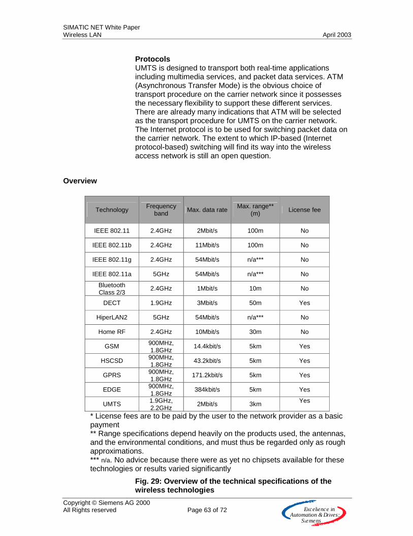
SIMATIC NET White Paper Wireless LAN April 2003
Copyright © Siemens AG 2000 All Rights reserved Page 63 of 72 E x c e lle n c e in
A u to m a tio n &Driv e s :S ie m e n s
Protocols UMTS is designed to transport both real-time applications including multimedia services, and packet data services. ATM (Asynchronous Transfer Mode) is the obvious choice of transport procedure on the carrier network since it possesses the necessary flexibility to support these different services. There are already many indications that ATM will be selected as the transport procedure for UMTS on the carrier network. The Internet protocol is to be used for switching packet data on the carrier network. The extent to which IP-based (Internet protocol-based) switching will find its way into the wireless access network is still an open question.
Overview
Technology Frequency band Max. data rate Max. range**
(m) License fee
IEEE 802.11 2.4GHz 2Mbit/s 100m No
IEEE 802.11b 2.4GHz 11Mbit/s 100m No
IEEE 802.11g 2.4GHz 54Mbit/s n/a*** No
IEEE 802.11a 5GHz 54Mbit/s n/a*** No
Bluetooth Class 2/3
2.4GHz 1Mbit/s 10m No
DECT 1.9GHz 3Mbit/s 50m Yes
HiperLAN2 5GHz 54Mbit/s n/a*** No
Home RF 2.4GHz 10Mbit/s 30m No
GSM 900MHz, 1.8GHz
14.4kbit/s 5km Yes
HSCSD 900MHz, 1.8GHz
43.2kbit/s 5km Yes
GPRS 900MHz, 1.8GHz
171.2kbit/s 5km Yes
EDGE 900MHz, 1.8GHz
384kbit/s 5km Yes
UMTS 1.9GHz, 2.2GHz
2Mbit/s 3km Yes
* License fees are to be paid by the user to the network provider as a basic payment ** Range specifications depend heavily on the products used, the antennas, and the environmental conditions, and must thus be regarded only as rough approximations. *** n/a. No advice because there were as yet no chipsets available for these technologies or results varied significantly
Fig. 29: Overview of the technical specifications of the wireless technologies
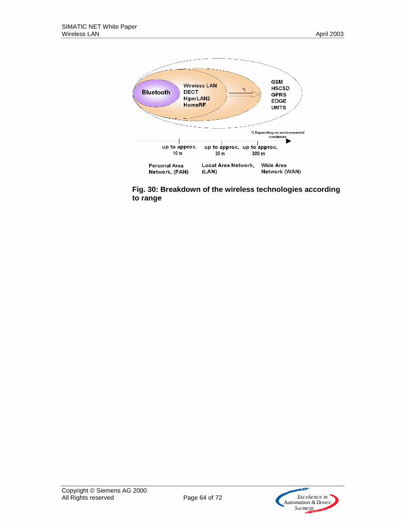
SIMATIC NET White Paper Wireless LAN April 2003
Copyright © Siemens AG 2000 All Rights reserved Page 64 of 72 E x c e lle n c e in
A u to m a tio n &Driv e s :S ie m e n s
Fig. 30: Breakdown of the wireless technologies according to range
SIMATIC NET White Paper Wireless LAN April 2003
Copyright © Siemens AG 2000 All Rights reserved Page 65 of 72 E x c e lle n c e in
A u to m a tio n &Driv e s :S ie m e n s
Mutual interference In discussing below the extent to which the above technologies interfere with each other, the focus is on the three most successful in the market (according to unit quantities): GSM, WLAN and Bluetooth. GSM is not critical here because regular interference is not to be expected thanks to the reserved frequency band (GSM900: 880..915MHz and 925..960MHz, GSM1800: 1710..1785MHz and 1805..1880MHz). The situation is different with WLAN and Bluetooth since both use the license-free ISM band at 2.4GHz. First, it must be established that both the frequency hopping procedure of Bluetooth and the DSSS modulation method of WLAN are robust against interference. With frequency hopping, the transmission frequency is changed extremely quickly, and with DSSS, high redundancy by means of a spread frequency spectrum is used. Bluetooth's fast changing of the transmission frequency can result in the frequency used being in the band of WLAN. However, a fault will only occur if the power of the Bluetooth transmitter is strong enough and the redundancy mechanisms of WLAN can no longer correct the fault. The physical proximity of the Bluetooth transmitter and the WLAN receiver is crucial in these considerations. It must be noted here that the usual Bluetooth Class 2/3 transmitters with 1mW transmitter power only cause genuine performance problems in the immediate vicinity of WLAN nodes. In addition, we show below that normally only a Bluetooth wireless network or a WLAN wireless network is used in a plant. Operators will think twice about doubling their investment and only in the rarest of cases will they see benefits. This reduces the question of interference to unwanted radiation from, say, mobile phones with an active Bluetooth interface. It also challenges plant operators themselves to introduce regulation. Just as factories have clear guidelines today regarding the division of manufacturing space or the routing of cable ducts, management of the active wireless systems will become necessary in future when it will not be acceptable for just any systems to be installed next to each other. A positive approach is expected in the specification of Bluetooth. Procedures will be implemented here that will avoid already used frequencies. It must also be taken into account that the frequency band at 5GHz, where such overlaps do not occur, has recently become available on WLAN.

SIMATIC NET White Paper Wireless LAN April 2003
Copyright © Siemens AG 2000 All Rights reserved Page 66 of 72 E x c e lle n c e in
A u to m a tio n &Driv e s :S ie m e n s
Glossary
2G 2nd generation digital mobile wireless networks, e.g. GSM
3G Third generation digital mobile wireless network, for example, UMTS The term 2.5G is also encountered in individual cases. Such cases refer to expansions of GSM (EDGE, GPRS)
IEC 61508 Standard for functional safety (new)
EN 954-1 Standard for functional safety (old)
Access point WLAN wireless networks are established with access points. They also connect the wired data network.
ACK Acknowledge Signal in the handshake protocol for the prevention of the hidden node problem
ACL Access Control List List with MAC addresses that are authorized to access the wireless network
Ad hoc network Wireless network between individual devices (point-to-point)
AES Advanced Encryption Standard New standard for encryption of data in WLANs
Antenna diversity Procedure in which a wireless receiver is equipped with two antennas and can select the better of two received signals
Antenna gain (Passive!) improvement of the antenna over isotropic transmitter achieved by suitable design.
ATM Asynchronous Transfer Mode Wired network used especially in the backbone for long distances at high data rates
BPSK Binary phase shift keying Modulation procedure on WLAN
BQTF Bluetooth Qualification Test Facility Facility for monitoring the interoperability of the products of different vendors
BSS Basic Service Set WLAN wireless network with access to the infrastructure via a single access point

SIMATIC NET White Paper Wireless LAN April 2003
Copyright © Siemens AG 2000 All Rights reserved Page 67 of 72 E x c e lle n c e in
A u to m a tio n &Driv e s :S ie m e n s
CCK Complementary code keying Modulation procedure on WLAN
CDMA Code Division Multiplex Code-driven access procedure
CF Compact flash
CFP Contention free period Period during which access is managed by the access point (to support time-critical services)
CP Contention Period Period during which access is managed in accordance with CSMA/CA (to support time-critical services)
CP Communications processor
CSMA/CA Carrier Sense Multiple Access with Collision Avoidance Access procedure of a wireless IEEE 802.11network
CSMA/CD Carrier Sense Multiple Access with Collision Detection Access procedure of a wired Ethernet network
CTS Clear to send Signal in the handshake protocol for prevention of the hidden node problem
DDE Dynamic Data Exchange
DCF Discrete coordinated function Normal access procedure on 802.11 in contrast to PCF
DECT Digital Enhanced Cordless Telecommunications, European standard for voice and data communication
DFS Dynamic Frequency Selection in the 5GHz band
Diversity Radio receiver with two antennas, allowing selection of better signal
DSSS Direct Sequence Spread Spectrum Spread band transmission method (IEEE 802.11b)
EDGE Enhanced Data Rates for Global Systems for Mobile Communications Evolution Further development of GSM with data rates up to 384kbit/s for video and wireless Internet applications
EHB Electric suspension monorail
EIRP Equivalent isotropic radiated power The power that needs to be supplied to an isotropic transmitter to enable it to effectively emit the same power as
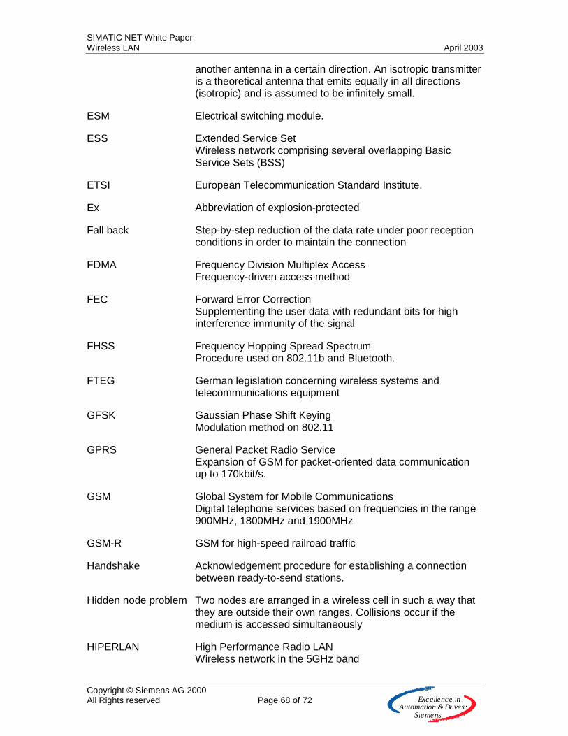
SIMATIC NET White Paper Wireless LAN April 2003
Copyright © Siemens AG 2000 All Rights reserved Page 68 of 72 E x c e lle n c e in
A u to m a tio n &Driv e s :S ie m e n s
another antenna in a certain direction. An isotropic transmitter is a theoretical antenna that emits equally in all directions (isotropic) and is assumed to be infinitely small.
ESM Electrical switching module.
ESS Extended Service Set Wireless network comprising several overlapping Basic Service Sets (BSS)
ETSI European Telecommunication Standard Institute.
Ex Abbreviation of explosion-protected
Fall back Step-by-step reduction of the data rate under poor reception conditions in order to maintain the connection
FDMA Frequency Division Multiplex Access Frequency-driven access method
FEC Forward Error Correction Supplementing the user data with redundant bits for high interference immunity of the signal
FHSS Frequency Hopping Spread Spectrum Procedure used on 802.11b and Bluetooth.
FTEG German legislation concerning wireless systems and telecommunications equipment
GFSK Gaussian Phase Shift Keying Modulation method on 802.11
GPRS General Packet Radio Service Expansion of GSM for packet-oriented data communication up to 170kbit/s.
GSM Global System for Mobile Communications Digital telephone services based on frequencies in the range 900MHz, 1800MHz and 1900MHz
GSM-R GSM for high-speed railroad traffic
Handshake Acknowledgement procedure for establishing a connection between ready-to-send stations.
Hidden node problem Two nodes are arranged in a wireless cell in such a way that they are outside their own ranges. Collisions occur if the medium is accessed simultaneously
HIPERLAN High Performance Radio LAN Wireless network in the 5GHz band
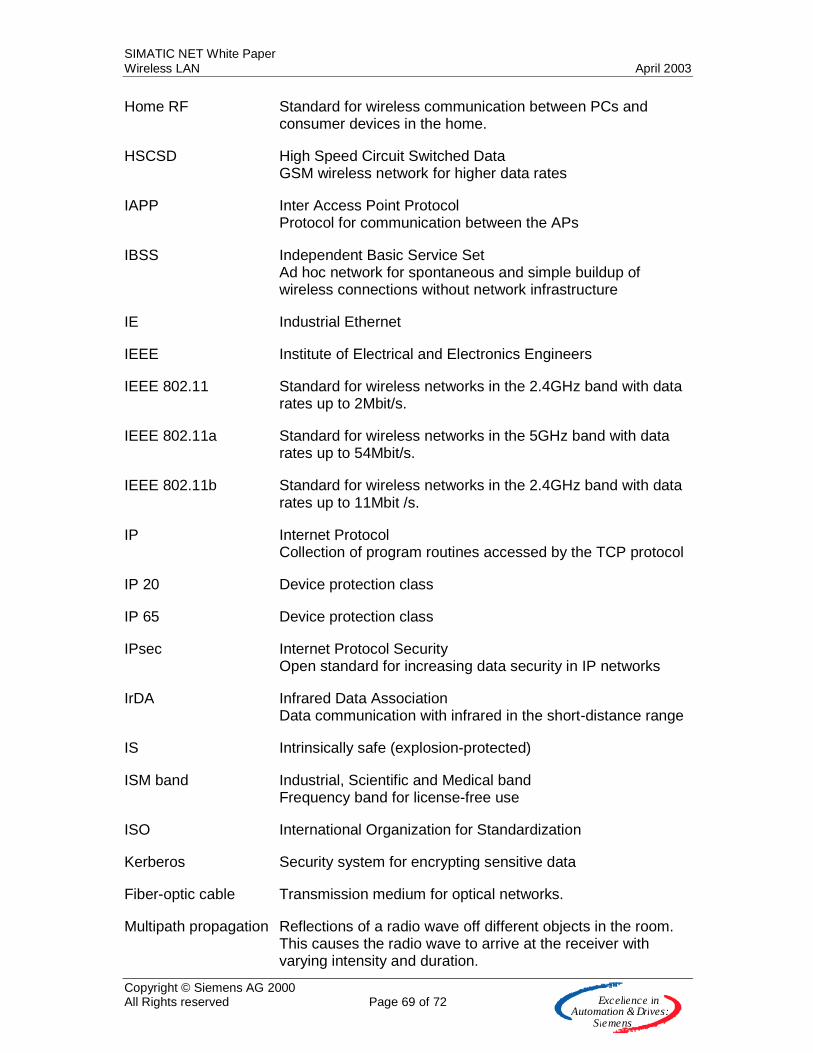
SIMATIC NET White Paper Wireless LAN April 2003
Copyright © Siemens AG 2000 All Rights reserved Page 69 of 72 E x c e lle n c e in
A u to m a tio n &Driv e s :S ie m e n s
Home RF Standard for wireless communication between PCs and consumer devices in the home.
HSCSD High Speed Circuit Switched Data GSM wireless network for higher data rates
IAPP Inter Access Point Protocol Protocol for communication between the APs
IBSS Independent Basic Service Set Ad hoc network for spontaneous and simple buildup of wireless connections without network infrastructure
IE Industrial Ethernet
IEEE Institute of Electrical and Electronics Engineers
IEEE 802.11 Standard for wireless networks in the 2.4GHz band with data rates up to 2Mbit/s.
IEEE 802.11a Standard for wireless networks in the 5GHz band with data rates up to 54Mbit/s.
IEEE 802.11b Standard for wireless networks in the 2.4GHz band with data rates up to 11Mbit /s.
IP Internet Protocol Collection of program routines accessed by the TCP protocol
IP 20 Device protection class
IP 65 Device protection class
IPsec Internet Protocol Security Open standard for increasing data security in IP networks
IrDA Infrared Data Association Data communication with infrared in the short-distance range
IS Intrinsically safe (explosion-protected)
ISM band Industrial, Scientific and Medical band Frequency band for license-free use
ISO International Organization for Standardization
Kerberos Security system for encrypting sensitive data
Fiber-optic cable Transmission medium for optical networks.
Multipath propagation Reflections of a radio wave off different objects in the room. This causes the radio wave to arrive at the receiver with varying intensity and duration.
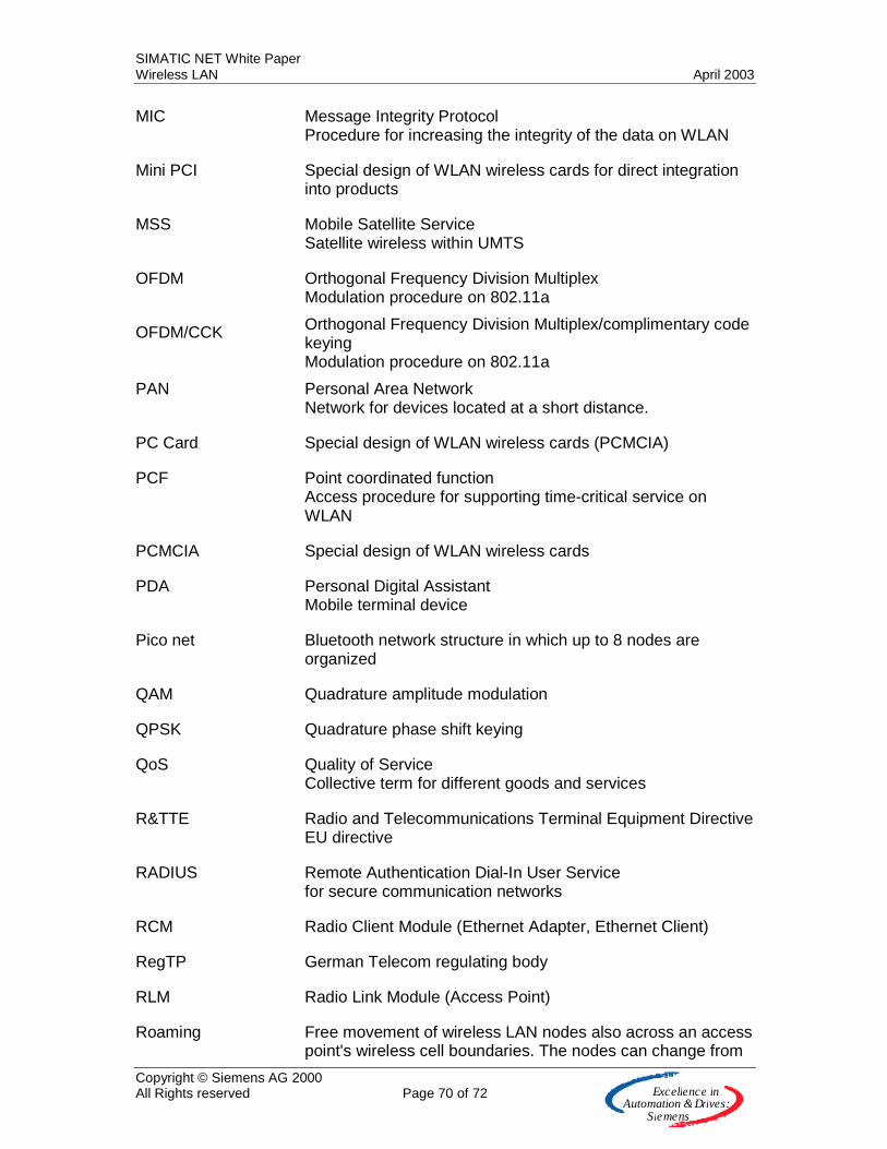
SIMATIC NET White Paper Wireless LAN April 2003
Copyright © Siemens AG 2000 All Rights reserved Page 70 of 72 E x c e lle n c e in
A u to m a tio n &Driv e s :S ie m e n s
MIC Message Integrity Protocol Procedure for increasing the integrity of the data on WLAN
Mini PCI Special design of WLAN wireless cards for direct integration into products
MSS Mobile Satellite Service Satellite wireless within UMTS
OFDM Orthogonal Frequency Division Multiplex Modulation procedure on 802.11a
OFDM/CCK Orthogonal Frequency Division Multiplex/complimentary code keying Modulation procedure on 802.11a
PAN Personal Area Network Network for devices located at a short distance.
PC Card Special design of WLAN wireless cards (PCMCIA)
PCF Point coordinated function Access procedure for supporting time-critical service on WLAN
PCMCIA Special design of WLAN wireless cards
PDA Personal Digital Assistant Mobile terminal device
Pico net Bluetooth network structure in which up to 8 nodes are organized
QAM Quadrature amplitude modulation
QPSK Quadrature phase shift keying
QoS Quality of Service Collective term for different goods and services
R&TTE Radio and Telecommunications Terminal Equipment Directive EU directive
RADIUS Remote Authentication Dial-In User Service for secure communication networks
RCM Radio Client Module (Ethernet Adapter, Ethernet Client)
RegTP German Telecom regulating body
RLM Radio Link Module (Access Point)
Roaming Free movement of wireless LAN nodes also across an access point's wireless cell boundaries. The nodes can change from

SIMATIC NET White Paper Wireless LAN April 2003
Copyright © Siemens AG 2000 All Rights reserved Page 71 of 72 E x c e lle n c e in
A u to m a tio n &Driv e s :S ie m e n s
one wireless cell to the next without perceptible interruption
RTS Request to send Signal in the handshake protocol for prevention of the hidden node problem
Scatternet Bluetooth network structure in which several piconets are organized
SIG Special Interest Group Bluetooth user organization
SNMP Simple Network Management Protocol, Standardized protocol for the transport of network management information
SSID Service Set Identifier Address Name of the wireless network on WLAN
TDMA Time Division Multiplex Access Time-slice-controlled access procedure
TPC Transmission power control Automatic regulation of the transmitter power in the 5GHz band
TKIP Temporal Key Integrity Protocol Procedure for cyclically changing the key on WLAN
UMTS Universal Mobile Telecommunications System Mobile wireless for mobile voice, audio, picture, video, and data communication
UNII Unlicensed National Information Infrastructure Name of the 5GHz band in the American literature
URAN UMTS Radio Access Network Wireless network of UMTS
UTRAN UMTS Terrestrial Radio Access Network Terrestrial part of the UMTS wireless network
WCDMA Wideband CDMA Modulation procedure for high data rates
WDS Wireless Distribution Systems For connecting the access points for an Extended Service Set (ESS)
Web Pad Portable device in DIN-A4 dimensions with touch screen for Internet use
WECA Wireless Ethernet Compatibility Alliance Alliance of wireless LAN product manufacturers who

SIMATIC NET White Paper Wireless LAN April 2003
Copyright © Siemens AG 2000 All Rights reserved Page 72 of 72 E x c e lle n c e in
A u to m a tio n &Driv e s :S ie m e n s
Alliance of wireless LAN product manufacturers who guarantee the compatibility of their products through tests.
WEP Wired Equivalent Privacy Encryption procedure on WLAN
Wi-Fi Siegel Wireless Fidelity Seal of the WECA for identifying compatible and tested products.
WLAN Wireless LAN (here: IEEE 802.11)
WLANA The Wireless LAN Association Consortium of wireless LAN vendors for spreading wireless LAN technology in the network market.