Embed Size (px)
Citation preview

SIMATIC IPC Support Package for
VxWorks
___________________
___________________
___________________
___________________
___________________
___________________
___________________
___________________
___________________
___________________
___________________
___________________
___________________
___________________
___________________
SIMATIC
Industrial PC SIMATIC IPC Support Package for VxWorks
Operating Manual
08/2015 A5E33664894-AB
Introduction 1
Description 2
Installation on the development computer
3
Generating a VxWorks image
4
Bootloader for VxWorks 5
Creating a downloadable kernel module
6
Creating a Real Time Process (RTP) application
7
Debugging a Real Time Process (RTP) application
8
Working with the shell 9
PROFINET driver 10
PROFIBUS driver 11
Hardware-dependent functions
12
DiagMonitor Agent for VxWorks
13
VxWorks V7 14
Service and support A

Siemens AG Division Digital Factory Postfach 48 48 90026 NÜRNBERG GERMANY
A5E33664894-AB Ⓟ 08/2015 Subject to change
Copyright © Siemens AG 2015. All rights reserved
Legal information Warning notice system
This manual contains notices you have to observe in order to ensure your personal safety, as well as to prevent damage to property. The notices referring to your personal safety are highlighted in the manual by a safety alert symbol, notices referring only to property damage have no safety alert symbol. These notices shown below are graded according to the degree of danger.
DANGER indicates that death or severe personal injury will result if proper precautions are not taken.
WARNING indicates that death or severe personal injury may result if proper precautions are not taken.
CAUTION indicates that minor personal injury can result if proper precautions are not taken.
NOTICE indicates that property damage can result if proper precautions are not taken.
If more than one degree of danger is present, the warning notice representing the highest degree of danger will be used. A notice warning of injury to persons with a safety alert symbol may also include a warning relating to property damage.
Qualified Personnel The product/system described in this documentation may be operated only by personnel qualified for the specific task in accordance with the relevant documentation, in particular its warning notices and safety instructions. Qualified personnel are those who, based on their training and experience, are capable of identifying risks and avoiding potential hazards when working with these products/systems.
Proper use of Siemens products Note the following:
WARNING Siemens products may only be used for the applications described in the catalog and in the relevant technical documentation. If products and components from other manufacturers are used, these must be recommended or approved by Siemens. Proper transport, storage, installation, assembly, commissioning, operation and maintenance are required to ensure that the products operate safely and without any problems. The permissible ambient conditions must be complied with. The information in the relevant documentation must be observed.
Trademarks All names identified by ® are registered trademarks of Siemens AG. The remaining trademarks in this publication may be trademarks whose use by third parties for their own purposes could violate the rights of the owner.
Disclaimer of Liability We have reviewed the contents of this publication to ensure consistency with the hardware and software described. Since variance cannot be precluded entirely, we cannot guarantee full consistency. However, the information in this publication is reviewed regularly and any necessary corrections are included in subsequent editions.

SIMATIC IPC Support Package for VxWorks Operating Manual, 08/2015, A5E33664894-AB 3
Table of contents
1 Introduction ............................................................................................................................................. 7
2 Description ............................................................................................................................................ 11
2.1 Overview ................................................................................................................................. 11
2.2 System environment ............................................................................................................... 12
2.3 Use of VxWorks V7 ................................................................................................................. 12
3 Installation on the development computer ............................................................................................. 13
4 Generating a VxWorks image ................................................................................................................ 15
4.1 Selecting BSPs for SIMATIC IPCs ......................................................................................... 15
4.2 Integrating components for the VxWorks image ..................................................................... 18
4.3 Configuring a VxWorks image ................................................................................................ 27 4.3.1 Making general settings for the VxWorks image .................................................................... 27 4.3.2 Reading boot parameters from the hard disk ......................................................................... 28 4.3.3 Configuring an Ethernet interface ........................................................................................... 28 4.3.4 Configuring the COM port or VGA port for output .................................................................. 29 4.3.5 Configuring the FTP connection ............................................................................................. 29 4.3.6 Enabling a connection for debugging ..................................................................................... 29
4.4 Additional useful components ................................................................................................. 30
4.5 Important information regarding VxWorks .............................................................................. 30
4.6 Initiating generation of a VxWorks image ............................................................................... 30
5 Bootloader for VxWorks ........................................................................................................................ 31
5.1 VxWorks BootApp ................................................................................................................... 32 5.1.1 Generating VxWorks BootApp ................................................................................................ 32 5.1.2 Installing VxWorks on the hard disk of the SIMATIC IPC ....................................................... 43
5.2 GRUB Bootloader ................................................................................................................... 46
5.3 GRUB Legacy Bootloader ...................................................................................................... 48
5.4 GRUB Bootloader and Windows ............................................................................................ 50
6 Creating a downloadable kernel module ................................................................................................ 55
7 Creating a Real Time Process (RTP) application ................................................................................... 59
8 Debugging a Real Time Process (RTP) application ............................................................................... 61
9 Working with the shell ........................................................................................................................... 65
9.1 Preventing a target shell timeout ............................................................................................ 65
9.2 Command line editing ............................................................................................................. 65

Table of contents
SIMATIC IPC Support Package for VxWorks 4 Operating Manual, 08/2015, A5E33664894-AB
10 PROFINET driver .................................................................................................................................. 67
10.1 PROFINET functions ............................................................................................................. 67
10.2 PROFINET driver ................................................................................................................... 68 10.2.1 CP 16xx driver........................................................................................................................ 68 10.2.2 PN driver ................................................................................................................................ 69
10.3 IO-Base interface ................................................................................................................... 69
10.4 Using PROFINET calls in the downloadable kernel module (DKM) ...................................... 69
10.5 Using PROFINET calls in the Real Time Process (user mode) ............................................ 70
10.6 Messages of the PROFINET driver ....................................................................................... 71
10.7 Configuring the PROFINET driver ......................................................................................... 72 10.7.1 Configuring the CP 16xx driver .............................................................................................. 72 10.7.2 Configuring the PN driver ....................................................................................................... 74
11 PROFIBUS driver.................................................................................................................................. 75
11.1 PROFIBUS functions ............................................................................................................. 75
11.2 DP-Base interface .................................................................................................................. 75 11.2.1 Programming manual for DP-Base interface ......................................................................... 75 11.2.2 Sending DP slave data (update of the information in the programming manual) .................. 75
11.3 Using PROFIBUS calls in the downloadable kernel module (DKM) ...................................... 77
11.4 Using PROFINET calls in the Real Time Process (user mode) ............................................ 78
11.5 Messages of the PROFIBUS driver ....................................................................................... 78
11.6 Configuring PROFIBUS ......................................................................................................... 79
11.7 Creating a configuration ......................................................................................................... 79 11.7.1 Configuring with SIMATIC Manager STEP7 .......................................................................... 80 11.7.2 Configuring with STEP 7 (TIA-Portal) .................................................................................... 82
12 Hardware-dependent functions ............................................................................................................. 85
12.1 Using hardware-dependent functions in the downloadable kernel module (DKM) ................ 85
12.2 Using hardware-dependent functions in the Real Time Process (user mode) ...................... 86
12.3 Messages of the driver ........................................................................................................... 86
12.4 Configuring hardware-dependent functions ........................................................................... 87
12.5 Access functions for hardware-dependent functions ............................................................. 89 12.5.1 GetCPUTypeDMI ................................................................................................................... 90 12.5.2 ReadTemperature .................................................................................................................. 91 12.5.3 ReadFanStatus ...................................................................................................................... 93 12.5.4 ReadBatteryStatus ................................................................................................................. 95 12.5.5 Operating hours counter ........................................................................................................ 95 12.5.5.1 SetOpHoursCounter .............................................................................................................. 96 12.5.5.2 GetOpHoursCounter .............................................................................................................. 97 12.5.5.3 UpdateOpHoursCounter ........................................................................................................ 98 12.5.6 Watchdog ............................................................................................................................... 99 12.5.6.1 StartWatchdog ....................................................................................................................... 99 12.5.6.2 TriggerWatchdog.................................................................................................................. 100

Table of contents
SIMATIC IPC Support Package for VxWorks Operating Manual, 08/2015, A5E33664894-AB 5
12.5.7 LED ....................................................................................................................................... 100 12.5.7.1 Setting an LED ...................................................................................................................... 101 12.5.7.2 Resetting LEDs ..................................................................................................................... 102 12.5.8 GetSMARTStatus ................................................................................................................. 103 12.5.9 GetCMOSDateTime .............................................................................................................. 104 12.5.10 SetCMOSDateTime .............................................................................................................. 105
13 DiagMonitor Agent for VxWorks .......................................................................................................... 107
13.1 Overview ............................................................................................................................... 107
13.2 DMAPI interface .................................................................................................................... 108
13.3 Operating hours counter of the DiagMonitor Agent .............................................................. 109
13.4 Creating a VxWorks image ................................................................................................... 109
13.5 Messages .............................................................................................................................. 115
13.6 Configuration ......................................................................................................................... 115
14 VxWorks V7 ........................................................................................................................................ 117
14.1 Installation on the development computer ............................................................................ 117
14.2 Generating an image ............................................................................................................ 118
14.3 Bootloader for VxWorks ........................................................................................................ 125
14.4 Creating a downloadable kernel module .............................................................................. 126
14.5 Generating a Real Time Process (RTP) application ............................................................. 126
14.6 Using PROFINET calls in the Real Time Process (user mode) ........................................... 127
A Service and support ............................................................................................................................ 129
Index................................................................................................................................................... 131

Table of contents
SIMATIC IPC Support Package for VxWorks 6 Operating Manual, 08/2015, A5E33664894-AB

SIMATIC IPC Support Package for VxWorks Operating Manual, 08/2015, A5E33664894-AB 7
Introduction 1
SIMATIC IPC You can install the real-time operating system VxWorks Runtime System V6.9 (32-bit) and VxWorks V7 (in compatibility mode V6.9, 32-bit) on the following SIMATIC IPCs:
● SIMATIC IPC227E
● SIMATIC IPC277E
● SIMATIC IPC427D
● SIMATIC IPC627D
● SIMATIC IPC647D
● SIMATIC IPC827D
● SIMATIC IPC847D
Topics in this manual ● Configuration of the hardware-dependent functions:
– CPU basic setting
– Temperature monitoring
– Fan monitoring
– Battery monitoring
– Watchdog
– User LEDs
– Retentive memory
– Operating hours counter
– SMART status monitoring
● Configuration of the following components included in the SIMATIC IPC Support Package for VxWorks:
– PROFIBUS driver for "PROFIBUS" on-board interface (compatible with CP 5622)
– PROFINET driver for "PROFINET" on-board interface (compatible with CP 1616)
– PROFINET driver for the "Ethernet" onboard interfaces
– SIMATIC IPC DiagMonitor Agent
● Handling the API functions of PROFIBUS DP (DP-Base interface)
● Handling the API functions of PROFINET (IO-Base interface)
● Handling the DMAPI functions

Introduction
SIMATIC IPC Support Package for VxWorks 8 Operating Manual, 08/2015, A5E33664894-AB
Target group This manual is intended for installation engineers and programmers who are familiar with the real-time operating system VxWorks.
Additional information You can find information dealing with the general structure and function of VxWorks in the VxWorks Application Programmer's Guide, VxWorks Kernel Programmer's Guide and the VxWorks API References.
You can find information about SIMATIC IPC227E, SIMATIC IPC277E, SIMATIC IPC427D, SIMATIC IPC627D, SIMATIC IPC647D, SIMATIC IPC827D and SIMATIC IPC847D in the operating instructions of the respective SIMATIC IPC (included in the SIMATIC IPC scope of delivery).
You can find general information about PROFINET as well as a description of access functions in the SIMATIC NET PROFINET programming manual "IO-Base User Programming Interface" ("PGH_IO-Base_76.pdf" file), which is included on the supplied CD.
You can find general information about PROFIBUS as well as a description of the access functions in the SIMATIC NET programming manual "DP-Base Programming Interface for CP 5613/CP 5614" ("mn_dp-base-api_76.pdf" file), which is included on the supplied CD.
Conventions
Designations
● The abbreviation IPC227E is also used for the product SIMATIC IPC227E.
● The abbreviation IPC277E is also used for the product SIMATIC IPC277E.
● The abbreviation IPC427D is also used for the product SIMATIC IPC427D.
● The abbreviation IPC627D is also used for the product SIMATIC IPC627D.
● The abbreviation IPC647D is also used for the product SIMATIC IPC647D.
● The abbreviation IPC827D is also used for the product SIMATIC IPC827D.
● The abbreviation IPC847D is also used for the product SIMATIC IPC847D.
● The term SIMATIC IPC is also used for all devices as a whole.
● The abbreviations CP 1616, CP 1616 on-board or CP 16xx are used for the PROFINET on-board interface of the SIMATIC IPC.
● The abbreviation CP 5622 is also used for the product SIMATIC NET PROFIBUS CP 5622 PCI EXPRESS X1-CARD.
● A PROFINET IO system consists of a PROFINET IO controller and its assigned PROFINET IO devices.
– The designation IO controller is used for a PROFINET IO controller.
– The designation IO device is used for a PROFINET IO device.
● The abbreviation "<WIND_BASE>" is also used for the path "<installDir>\WindRiver\vxworks-6.9" or "<installDir>\WindRiver\vxworks-7".

Introduction
SIMATIC IPC Support Package for VxWorks Operating Manual, 08/2015, A5E33664894-AB 9
Figures
The screenshots in this manual were created with Wind River Workbench V3.3.6 (VxWorks V6.9) or Wind River Workbench V4.0.5 (VxWorks V7). If you are using a different version, your screens may differ from these screenshots.
Industrial Security Siemens offers products and solutions with Industrial Security functions that support the safe operation of equipment, solutions, machines, devices and/or networks. They are important components in a comprehensive Industrial Security concept. As a result the products and solutions from Siemens are constantly evolving. Siemens recommends obtaining regular information regarding product updates.
For safe operation of Siemens products and solutions appropriate protective measures (e.g., cell protection concept) must be taken and each component must be integrated in a comprehensive Industrial Security concept, which corresponds with the current state of technology. The products of other manufacturers need to be taken into consideration if they are also used. You can find addition information on Industrial Security under (http://www.siemens.com/industrialsecurity).
Sign up for our product-specific newsletter to receive the latest information on product updates. For more information, see under (http://www.siemens.de/automation/csi_en_WW).
Disclaimer for third-party software updates This product includes third-party software. Siemens AG only provides a warranty for updates/patches of the third-party software, if these have been distributed as part of a Siemens software update service contract or officially released by Siemens AG. Otherwise, updates/patches are undertaken at your own risk. You can find more information about our Software Update Service offer on the Internet at Software Update Service (http://www.automation.siemens.com/mcms/automation-software/en/software-update-service).
Notes on protecting administrator accounts A user with administrator privileges has extensive access and manipulation options in the system.
Therefore, ensure there are adequate safeguards for protecting the administrator accounts to prevent unauthorized changes. To do this, use secure passwords and a standard user account for normal operation. Other measures, such as the use of security policies, should be applied as needed.

Introduction
SIMATIC IPC Support Package for VxWorks 10 Operating Manual, 08/2015, A5E33664894-AB

SIMATIC IPC Support Package for VxWorks Operating Manual, 08/2015, A5E33664894-AB 11
Description 2 2.1 Overview
The SIMATIC IPC Support Package for VxWorks supports the additional hardware interfaces of SIMATIC IPCs which are not supported by VxWorks, e.g. PROFIBUS, PROFINET and hardware-dependent functions (e.g. reading out the temperature). The Support Package contains the drivers and application examples necessary for creating customer-specific applications both in kernel and in RTP mode.
Of the various Wind River product variants of the VxWorks real-time operating system, the "Platform for Industrial Devices" is used. From this platform, the VxWorks Runtime System V6.9 (32-bit) is used as runtime environment and the Workbench V3.3 is used as development environment, or the VxWorks Runtime System V7 (32-bit) is used as runtime environment and the Workbench V4 as development environment.
To allow you to use the functionalities, the SIMATIC IPC Support Package for VxWorks is installed on the development computer. The target system can then be commissioned. Important basic settings must be prepared on the development computer and transferred to the target system.
The SIMATIC IPC Support Package for VxWorks contains online help and code completion for the PROFIBUS, PROFINET and hardware-dependent functions.

Description 2.2 System environment
SIMATIC IPC Support Package for VxWorks 12 Operating Manual, 08/2015, A5E33664894-AB
2.2 System environment
Development system Component Requirements Hardware PC Operating system Windows 7 (32-bit or 64-bit) Configuration software for PROFIBUS DP
STEP 7 as of version 5.5 SP3 Hotfix 3 (optional) STEP 7 (TIA Portal) as of V13 (optional) NCM PC as of version 5.5 SP3 from Developer Kit DK-16xx PN IO (optional)
Configuration software for PROFINET STEP 7 as of version 5.5 SP3 with Hardware Support Package HSP 1084 and 1085 (CP 1616 onboard V2.6) (optional) STEP 7 (TIA Portal) as of V13 (optional) NCM PC as of version 5.5 SP3 from Developer Kit DK-16xx PN IO (optional)
Development tools Workbench V3.3 for VxWorks V6.9 Workbench V4 for VxWorks V7
The configuration software can be downloaded at: Service and support (Page 129).
Target system Component Requirements Hardware SIMATIC IPC227E or
SIMATIC IPC277E or SIMATIC IPC427D or SIMATIC IPC627D or SIMATIC IPC647D or SIMATIC IPC827D or SIMATIC IPC847D
Operating system VxWorks V6.9 (32-bit) or higher VxWorks V7 or higher in compatibility mode V6.9 (32-bit)
2.3 Use of VxWorks V7 The following sections apply to VxWorks 6.9. The special features of VxWorks V7 are described in the following section: VxWorks V7 (Page 117).
SIMATIC IPC Support Package for VxWorks Operating Manual, 08/2015, A5E33664894-AB 13
Installation on the development computer 3
Procedure To install the SIMATIC IPC Support Package for VxWorks 6.9, follow these steps:
1. Insert the product CD into the drive of your development computer.
2. Start the file manager (e.g. Explorer).
3. Call the "setup.exe" program on the product CD in the folder "IPC_Support_Package_for _VxWorks_6.9" and follow the instructions.
Result The installation is complete.
Storage of the files in the file system After the installation, the files are stored in the following directory tree: (<WIND_BASE>\target\3rdparty\siemens) | +---docs | *.pdf Documentation for Siemens components | +---examples | *.* Examples for Siemens components | +---h | *.h Header files for Siemens components | +---lib | lib*.a Library for Siemens components | \--- <additional directories and files>
Please observe the Readme file with important information on the SIMATIC IPC Support Package for VxWorks.
The Readme file is located in the main directory of the CD and in the directory "<WIND_BASE>\target\3rdparty\siemens".

Installation on the development computer
SIMATIC IPC Support Package for VxWorks 14 Operating Manual, 08/2015, A5E33664894-AB

SIMATIC IPC Support Package for VxWorks Operating Manual, 08/2015, A5E33664894-AB 15
Generating a VxWorks image 4 4.1 Selecting BSPs for SIMATIC IPCs
The following SIMATIC IPCs are suitable for the following BSPs of VxWorks: SIMATIC IPC BSP from VxWorks Board bundle IPC427D itl_sandybridge Intel Emerald Lake II IPC227E, IPC277E,IPC627D, IPC827D, IPC647D, IPC847D
itl_haswell Intel Flathead Creek
All SIMATIC IPCs with Intel boards itl_x86 -
Creating a new VxWorks image project 1. Open Wind River Workbench.
You can find it in the Windows Start menu under "Start > All programs > Wind River > Workbench".
2. Select a Workspace in which you want to create your VxWorks-Image Project.
3. Select "File > New > Project".
4. In the following dialog window, open the "VxWorks 6.x" folder in list box and then select the option "VxWorks Image Project".
5. Click "Next>".
6. In the following dialog window, enter a "Project name" (e.g. "vip_ipc427d") and select the option "Create project in workspace".
7. Click "Next>".

Generating a VxWorks image 4.1 Selecting BSPs for SIMATIC IPCs
SIMATIC IPC Support Package for VxWorks 16 Operating Manual, 08/2015, A5E33664894-AB
8. Select the BSP and the Tool chain.
– Under BSP, select the appropriate entry for your SIMATIC IPC (e.g. "itl_sandybridge").
– Under "Tool chain", select the entry "gnu".
– If the target system is to communicate with the Workbench (for debugging purposes), select the option "Enable WDB Target Agent". For reasons of security (unauthorized access from the outside), the WDB Target Agent should only be enabled during development.
9. Enable multiprocessor support (SMP).
Generating a VxWorks image 4.1 Selecting BSPs for SIMATIC IPCs
SIMATIC IPC Support Package for VxWorks Operating Manual, 08/2015, A5E33664894-AB 17
10. Select the profile.
Workbench offers various profiles for generating a VxWorks image . Certain components are automatically included depending on the profile. If, for example, the "PROFILE_STANDALONE_DEVELOPMENT" profile is used, the icon management is located on the target. "no profile" is selected in the following example.
11. Skip the next dialog, "Indexer".
12. Click "Finish".

Generating a VxWorks image 4.2 Integrating components for the VxWorks image
SIMATIC IPC Support Package for VxWorks 18 Operating Manual, 08/2015, A5E33664894-AB
4.2 Integrating components for the VxWorks image Specific modules are added, configured, or removed in the selected BSP. This also depends on the bootloader used.
Based on "no profile" and no "WDB Target Agent", the following settings are required.
The steps in the following example are valid for the IPC427D with the BSP "itl_sandybridge". Other IPCs may require different steps.
Integrating a board bundle 1. Select the project view.
2. Double-click on "Kernel Configuration" in the tree.

Generating a VxWorks image 4.2 Integrating components for the VxWorks image
SIMATIC IPC Support Package for VxWorks Operating Manual, 08/2015, A5E33664894-AB 19
The area for the "Component Configuration" opens. This area contains various components arranged in groups (folders). Double-clicking on the group displays the subcomponents of the group.

Generating a VxWorks image 4.2 Integrating components for the VxWorks image
SIMATIC IPC Support Package for VxWorks 20 Operating Manual, 08/2015, A5E33664894-AB
3. Select the "Bundles" tab.
4. Right-click on bundle that is suitable for your IPC, in this example it is the "Intel Emerald Lake II Board bundle". Select "Add" from the shortcut menu.
Adding this bundle automatically includes the components "Emerald Lake II Board Component", "ACPI CPU configuration component" and "ACPI MP APIC boot".

Generating a VxWorks image 4.2 Integrating components for the VxWorks image
SIMATIC IPC Support Package for VxWorks Operating Manual, 08/2015, A5E33664894-AB 21
Integrating the CP 16xx driver 1. Select additional components in the "Components" tab.
"Ctrl + F" opens a dialog for searching for specific components. Under "Find scope", you can select the "Name" or "Description" filter.
2. Select the "Name" filter under "Find scope".
Generating a VxWorks image 4.2 Integrating components for the VxWorks image
SIMATIC IPC Support Package for VxWorks 22 Operating Manual, 08/2015, A5E33664894-AB
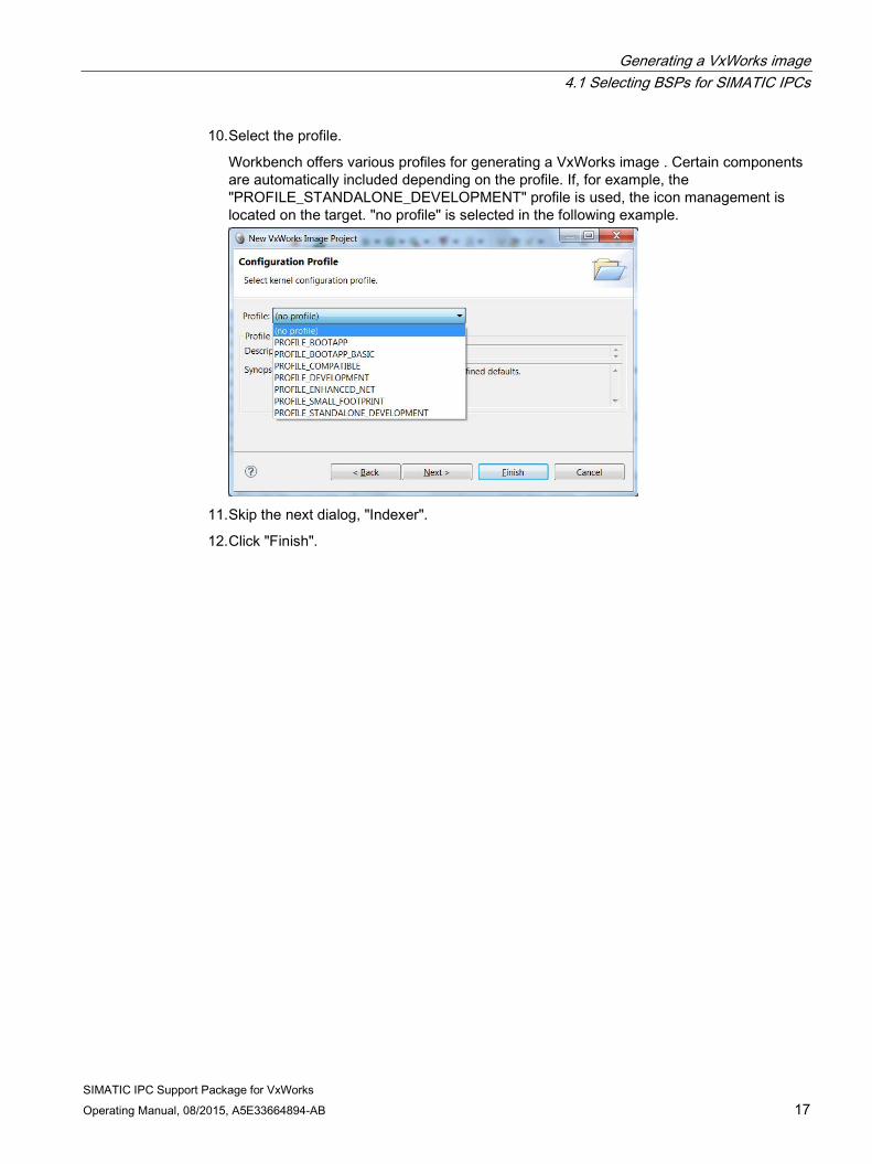
3. To search for the CP 16xx driver for PROFINET, enter the search text "INCLUDE_PROFINET_CP16XX" in the "Pattern" input box.
4. Click "Find".

Generating a VxWorks image 4.2 Integrating components for the VxWorks image
SIMATIC IPC Support Package for VxWorks Operating Manual, 08/2015, A5E33664894-AB 23
5. Right-click the selected driver and select "Include".

Generating a VxWorks image 4.2 Integrating components for the VxWorks image
SIMATIC IPC Support Package for VxWorks 24 Operating Manual, 08/2015, A5E33664894-AB
6. The driver is included. All components needed by the driver are automatically selected.
7. Include the other drivers of the SIMATIC IPC Support Package for VxWorks in the same
way.
Note that you can integrate only one of the two PROFINET drivers. You can find additional information on the PROFINET drivers in the section: PROFINET functions (Page 67).
– SIMATIC IPC DiagMonitor Agent
– SIMATIC IPC hardware dependent functions
– SIMATIC NET CP 5622 PROFIBUS
– SIMATIC NET CP 16XX PROFINET
– SIMATIC NET PN PROFINET
Integrating additional components Include additionally desired components as described above.
To access to the file system (AHCI and USB), TCP/IP and a shell, include the following components from the default tree of VxWorks.

Generating a VxWorks image 4.2 Integrating components for the VxWorks image
SIMATIC IPC Support Package for VxWorks Operating Manual, 08/2015, A5E33664894-AB 25
Components The following list contains the components that are automatically included, and components that need to be selected marked with the following symbols:
● Components that are automatically included
○ Components that must be selected manually ○ Multi-stage warm reboot type (INCLUDE_MULTI_STAGE_WARM_REBOOT) ● Multi-stage boot support (INCLUDE_MULTI_STAGE_BOOT) ○ AHCI SATA Controller (INCLUDE_DRV_STORAGE_AHCI) ● File System Event Utilities (INCLUDE_FS_EVENT_UTIL) ● Raw file system (INCLUDE_RAWFS) ● Event Reporting Framework (INCLUDE_ERF) ● File System Monitor (INCLUDE_FS_MONITOR) ● Extended Block Device (INCLUDE_XBD) ● Device Manager (INCLUDE_DEVICE_MANAGER) ○ PC Console (INCLUDE_PC_CONSOLE) ● Motorola 6845 VGA driver (DRV_VGA_M6845) ● Intel 8042 keyboard driver (DRV_KBD_I8042) ○ EHCI Init (INCLUDE_EHCI_INIT) ● USB Common Stack (INCLUDE_USB) ● USB Common Stack Init (INCLUDE_USB_INIT) ● EHCI (INCLUDE_EHCI) ● USB Host Controller Start (INCLUDE_HCD_BUS) ○ USB GEN2 Mass Storage Init (INCLUDE_USB_GEN2_STORAGE_INIT) ● XBD Block Device (INCLUDE_XBD_BLK_DEV) ● USB Host Class Driver Init (INCLUDE_USB_HOST_CLASS_INIT) ● USB GEN2 Helper Init (INCLUDE_USB_GEN2_HELPER) ● USB GEN2 Mass Storage (INCLUDE_USB_GEN2_STORAGE) ○ dosFs File System Components (dosFs2) (FOLDER_DOSFS2) ● DOS File System VFAT Directory Handler (INCLUDE_DOSFS_DIR_VFAT) ○ DOS File System FAT12/16/32 Handler (default) (INCLUDE_DOSFS_FAT) ○ Dos FS BIO buffer size (default) (INCLUDE_DOSFS_VOL_BIO_BUFFER_SIZE) ○ Dos FS Show Routines (default) (INCLUDE_DOSFS_SHOW) ○ DosFs File System Main Module (dosFs2) (default) (INCLUDE_DOSFS_MAIN) ○ Print message level (default) (INCLUDE_DOSFS_PRTMSG_LEVEL) ○ Kernel shell components (FOLDER_SHELL) ● Extended object library(INCLUDE_OBJ_OPEN) ● RTP (INCLUDE_RTP) ● Memory show routine (INCLUDE_MEM_SHOW) ● Vm library show routine(INCLUDE_VM_SHOW) ● Task hook show routine (INCLUDE_TASK_HOOKS_SHOW)

Generating a VxWorks image 4.2 Integrating components for the VxWorks image
SIMATIC IPC Support Package for VxWorks 26 Operating Manual, 08/2015, A5E33664894-AB
● Task show routine (INCLUDE_TASK_SHOW) ● Tip serial line connection utility (INCLUDE_TIP) ● Object management ownership (INCLUDE_OBJ_OWNERSHIP) ● VxWorks events (INCLUDE_VXEVENTS) ● Semaphore exchange routine (INCLUDE_SEM_EXCHANGE) ● C++ symbol demangler (INCLUDE_CPLUS_DEMANGLER) ● File System and Disk Utilities (INCLUDE_DISK_UTIL) ● Pseudo terminal driver (INCLUDE_PTYDRV) ● Target loader (INCLUDE_LOADER) ● RTP Hook support (INCLUDE_RTP_HOOKS) ● SYSCTL (INCLUDE_SYSCTL) ● Memory mapping (INCLUDE_MMAP) ● Host/target breakpoint synchronization (INCLUDE_WDB_BP_SYNC) ● WDB RTP support (INCLUDE_WDB_RTP) ● WDB RTP breakpoints (INCLUDE_WDB_RTP_BP) ● WDB RTP control support (INCLUDE_WDB_RTP_CONTROL) ● Debugging facilities (INCLUDE_DEBUG) ● Host/target modules and symbols synchronization
(INCLUDE_WDB_MDL_SYM_SYNC) ● RTP Show (INCLUDE_RTP_SHOW) ● Built-in symbol table (INCLUDE_STANDALONE_SYM_TBL) ● Target unloader (INCLUDE_UNLOADER) ● Symbol table show routines (INCLUDE_SYM_TBL_SHOW) ● Socket API System Call support (INCLUDE_SC_SOCKLIB) ● Target symbol table (INCLUDE_SYM_TBL) ● System symbol table initialization (INCLUDE_SYM_TBL_INIT) ● NETWORK SYSCTL (INCLUDE_NET_SYSCTL) ● System Call Hook Support (INCLUDE_SYSCALL_HOOKS) ● System Address Space Allocator (INCLUDE_ADR_SPACE_LIB) ● Address Space Allocator Show Routines (INCLUDE_ADR_SPACE_SHOW) ● Debug shell commands (INCLUDE_DEBUG_SHELL_CMD) ● Virtual memory show shell commands (INCLUDE_VM_SHOW_SHELL_CMD) ● Address space shell commands (INCLUDE_ADR_SPACE_SHELL_CMD) ● Target loader shell command (INCLUDE_MODULE_SHELL_CMD) ● Unloader shell command (INCLUDE_UNLOADER_SHELL_CMD) ● Coprocessor show routine (INCLUDE_COPROCESSOR_SHOW) ● IPNet sysctl integration (INCLUDE_IPNET_SYSCTL) ● Host table sysctl support (INCLUDE_HOST_TBL_SYSCTL) ● Remote Command sysctl support (INCLUDE_REMLIB_SYSCTL) ○ C line interpreter (default) (INCLUDE_SHELL_INTERP_C) ○ Command line interpreter (INCLUDE_SHELL_INTERP_CMD)

Generating a VxWorks image 4.3 Configuring a VxWorks image
SIMATIC IPC Support Package for VxWorks Operating Manual, 08/2015, A5E33664894-AB 27
○ File system shell commands (INCLUDE_DISK_UTIL_SHELL_CMD) ○ Process shell commands (INCLUDE_RTP_SHELL_CMD) ○ Process show shell commands (INCLUDE_RTP_SHOW_SHELL_CMD) ○ Serial line connection commands (INCLUDE_TIP_CMD) ○ Shell banner (default) (INCLUDE_SHELL_BANNER) ○ Symbol shell commands (INCLUDE_SYM_SHELL_CMD) ○ Target-resident kernel shell (default) (INCLUDE_SHELL) ○ Task shell commands (INCLUDE_TASK_SHELL_CMD) ○ USB GEN2 keyboard attaching to vxWorks Shell
(INCLUDE_USB_GEN2_KEYBOARD_SHELL_ATTACH) ● USB GEN2 Keyboard (INCLUDE_USB_GEN2_KEYBOARD) ● USB GEN2 Keyboard Init (INCLUDE_USB_GEN2_KEYBOARD_INIT) ○ PING Components (FOLDER_PING) ● Getopt function (INCLUDE_GETOPT) ● Ping wrapper (INCLUDE_IPWRAP_PING) ● IPCOM shell command interface (INCLUDE_IPCOM_SHELL_CMD) ○ IPCOM ping commands (INCLUDE_IPPING_CMD) ○ PING client (INCLUDE_PING)
4.3 Configuring a VxWorks image To configure the VxWorks image, press "Ctrl + F" to open a search dialog and then make the following settings.
4.3.1 Making general settings for the VxWorks image
Timer tick Set the timer tick to 1000, i.e. a tick interval is then 1 millisecond.
The timer tick is set with "SYS_CLK_RATE".
Sign-on message (banner) of the shell You can remove the sign-on messages (banners) of the shell by excluding this component.
The value "exclude" for "INCLUDE_SHELL_BANNER".
Number of cores Set the number of cores with "VX_SMP_NUM_CPUS". The number of cores depends on the installed CPU and the BIOS settings of your IPC.

Generating a VxWorks image 4.3 Configuring a VxWorks image
SIMATIC IPC Support Package for VxWorks 28 Operating Manual, 08/2015, A5E33664894-AB
4.3.2 Reading boot parameters from the hard disk When you start VxWorks from a hard disk (boot line is read from ataX:X/nvram.txt). you need the following additional components:
● AHCI warm start device component (INCLUDE_SYS_WARM_AHCI)
– DOS file system backward-compatibility (INCLUDE_DOSFS)
– DOS File System Volume Formatter Module (INCLUDE_DOSFS_FMT)
– DOS File System Consistency Checker (INCLUDE_DOSFS_CHKDSK)
– DOS File System Old Directory Format Handler (INCLUDE_DOSFS_DIR_FIXED)
● Driver for file-based non-volatile RAM support (DRV_NVRAM_FILE)
The following settings are required for the "INCLUDE_SYS_WARM_AHCI" component: Parameter Value BOOTROM_DIR 1 "/ata0:1" NV_RAM_SIZE (0x1000) SYS_WARM_TYPE SYS_WARM_AHCI 1 The BOOTROM_DIR parameter specifies the hard disk from which the "nvram.txt" file with the
boot parameters is read. Determine whether you need to adapt this value.
4.3.3 Configuring an Ethernet interface Set the IP address with "INCLUDE_BSP_MACROS" > "DEFAULT_BOOT_LINE" (the IP address of the target is "192.168.1.62"):
DEFAULT_BOOT_LINE: "fs(0,0)host:/ata0:1/vxWorks e=192.168.1.62 o=gei0 tn=IPC427D"
Note: "IPC427D" was specified as an example for the "tn" parameter (target name).
Second Ethernet interface
You need the following components for a second Ethernet interface:
● Interface #2 configuration (INCLUDE_IPNET_IFCONFIG_2)
IFCONFIG_2 "ifname gei1","devname gei1","inet 192.168.2.62", "gateway driver"

Generating a VxWorks image 4.3 Configuring a VxWorks image
SIMATIC IPC Support Package for VxWorks Operating Manual, 08/2015, A5E33664894-AB 29
4.3.4 Configuring the COM port or VGA port for output Configure the VGA interface as follows:
● Add "INCLUDE_PC_CONSOLE".
Configure the COM port as follows:
● Remove "INCLUDE_PC_CONSOLE".
● Remove "INCLUDE_USB_GEN2_KEYBOARD_SHELL_ATTACH".
● Add "INCLUDE_SIO".
– Set the baud rate of the COM port with "CONSOLE_BAUD_RATE" (e.g. 115200).
– Select the COM port to be used with "CONSOLE_TTY" (COM1 = 0, COM2 = 1).
4.3.5 Configuring the FTP connection Add the following include for the FTP connection: FTP Server (INCLUDE_IPFTPS)
Set the following 2 parameters (e.g., for the hard disk): FTPS_INITIAL_DIR "/ata0:1" FTPS_ROOT_DIR "/ata0:1"
Result You can connect to the server in VxWorks. A user is not evaluated for this. You can log on with any user name and no password (e.g. ftp://192.168.1.62).
Note
A user name and password should be assigned for productive operation.
4.3.6 Enabling a connection for debugging You can enable the TCP/IP debug connection to Workbench. Make the following setting:
● WDB is always enabled (INCLUDE_WDB_ALWAYS_ENABLED)
Select "INCLUDE_WDB_TSFS" to debug applications that were generated as "Real Time Process Project (RTP)".

Generating a VxWorks image 4.4 Additional useful components
SIMATIC IPC Support Package for VxWorks 30 Operating Manual, 08/2015, A5E33664894-AB
4.4 Additional useful components ● Spy CPU activity commands (INCLUDE_SPY_SHELL_CMD)
– Auxiliary clock (INCLUDE_AUX_CLK)
– Spy (INCLUDE_SPY)
– vxBus Aux Clk Support (INCLUDE_VXB_AUX_CLK)
● IPCOM ifconfig commands (INCLUDE_IPIFCONFIG_CMD)
– IPCOM shell command interface (INCLUDE_IPCOM_SHELL_CMD)
4.5 Important information regarding VxWorks
Note
You can find important information regarding limitations of VxWorks in the readme file.
You can find the readme file in the main directory of the CD or in the installation directory of the SIMATIC IPC Support Package for VxWorks.
4.6 Initiating generation of a VxWorks image You start the generation of the VxWorks image via "Project > Build Project".

SIMATIC IPC Support Package for VxWorks Operating Manual, 08/2015, A5E33664894-AB 31
Bootloader for VxWorks 5
Various bootloaders can be used. Bootloaders are described below:
● VxWorks BootApp
● GRUB Bootloader
● GRUB Legacy BootLoader
Use GRUB if an operating system is already installed and you also want to use VxWorks.
If you have any problems with the VxWorks bootloader, please contact Wind River.
General requirement for GRUB 1. To generate the VxWorks image, select "Properties/Build
Properties/Variables/EXTRA_DEFINE".
2. Set the define ""-DGRUB_MULTIBOOT".

Bootloader for VxWorks 5.1 VxWorks BootApp
SIMATIC IPC Support Package for VxWorks 32 Operating Manual, 08/2015, A5E33664894-AB
5.1 VxWorks BootApp
5.1.1 Generating VxWorks BootApp The following steps apply to the "itl_sandybridge" BSP and may differ for other BSPs.
1. Open Wind River Workbench.
You can find it in the Windows Start menu under "Start > All programs > Wind River > Workbench".
2. Select a Workspace in which you want to create your VxWorks Image Project.
3. Select "File > New > Project".
4. In the following dialog window, open the "VxWorks 6.x" folder in list box and then select the option "VxWorks Image Project".
5. Click "Next".
6. Enter "VIP_sandyBootApp", for example, for the "Project name".

Bootloader for VxWorks 5.1 VxWorks BootApp
SIMATIC IPC Support Package for VxWorks Operating Manual, 08/2015, A5E33664894-AB 33
7. Select the value "itl_sandybridge" under "BSP". WDB Target Agent is not enabled.
8. SMP support is not needed in the bootloader. Therefore, skip the next dialog, "Options".
Under "Profile", select the value "PROFILE_BOOTAPP_BASIC" and click "Finish" .
9. Right-click on the created project in the tree and open the "Properties" project settings.

Bootloader for VxWorks 5.1 VxWorks BootApp
SIMATIC IPC Support Package for VxWorks 34 Operating Manual, 08/2015, A5E33664894-AB
10. Select the "default_romCompress" option in the "Active build spec" list box of the "Spec" tab. This option is required because a compressed image needs to be generated.
11. The memory addresses used are taken from the "target.ref" description of the
"itl_sandyridge" BSP.
Make the following settings in the "Variables" tab:
Set the value of the "ROM_SIZE" to "00200000".

Bootloader for VxWorks 5.1 VxWorks BootApp
SIMATIC IPC Support Package for VxWorks Operating Manual, 08/2015, A5E33664894-AB 35
Set the value of "ROM_TEXT_ADRS" to "00408000".
12. Double-click on "Kernel Configuration" in the tree in the "Project Explorer" in your project.

Bootloader for VxWorks 5.1 VxWorks BootApp
SIMATIC IPC Support Package for VxWorks 36 Operating Manual, 08/2015, A5E33664894-AB
13. Open the "Bundles" tab and right-click on the "Intel Emerald Lake II Board bundle" bundle with the name "BUNDLE_EMERALD_LAKE_II_BOOTAPP".
Select "Add" from the shortcut menu.

Bootloader for VxWorks 5.1 VxWorks BootApp
SIMATIC IPC Support Package for VxWorks Operating Manual, 08/2015, A5E33664894-AB 37
14. Open the "Bundles" tab and right-click on the "Multi Stage Boot Warm Reboot bundle" bundle with the name "BUNDLE_MSB_WARM_REBOOT".
Select "Add" from the shortcut menu.

Bootloader for VxWorks 5.1 VxWorks BootApp
SIMATIC IPC Support Package for VxWorks 38 Operating Manual, 08/2015, A5E33664894-AB
15. Select the "Components" tab.
The VxWorks boot parameters on the USB device /bd0 are expected as default settings.
The associated component is "USB warm start device component" with the name "INCLUDE_SYS_WARM_USB".
If you boot from the hard disk, right-click on the "AHCI warm start device component" component with the name "INCLUDE_SYS_WARM_AHCI".
Select "Include (quick include)" from the shortcut menu.
The required driver for the hard disk, "INCLUDE_DRV_STORAGE_AHCI", is included automatically.
Make sure that the "Boot Application FILESYSTEM Support" with the name "INCLUDE_BOOT_FILESYSTEMS" is integrated.
This means the boot line is read from from the device /ata0:1.

Bootloader for VxWorks 5.1 VxWorks BootApp
SIMATIC IPC Support Package for VxWorks Operating Manual, 08/2015, A5E33664894-AB 39
16. Navigate to "peripherals" in the tree and then to the serial port "SIO".
Adjust the baud rate of the "baud rate of the console port" boot console to the setting of the VxWorks image to be loaded. The baud rate is 115200 in this example.
Note
If the INCLUDE_PC_CONSOLE component is included, remove this by right-clicking on the component and then clicking on "Exclude (quick exclude)" in the shortcut menu.

Bootloader for VxWorks 5.1 VxWorks BootApp
SIMATIC IPC Support Package for VxWorks 40 Operating Manual, 08/2015, A5E33664894-AB
17. In the tree of your project in the "Project Explorer", right-click on the target "vxWorks.bin".
Select "Build Target" from the shortcut menu.
The second stage loader "vxWorks_romCompress.bin" is created.

Bootloader for VxWorks 5.1 VxWorks BootApp
SIMATIC IPC Support Package for VxWorks Operating Manual, 08/2015, A5E33664894-AB 41
18. The first stage loader "vxStage1Boot.bin" is required.
Right-click in the tree on your project in the "Project Explorer".
Select "New" and then "Build Target".
19. In the "Build target name" box, enter "vxStage1Boot.bin" and click "Finish".
The new target is created.

Bootloader for VxWorks 5.1 VxWorks BootApp
SIMATIC IPC Support Package for VxWorks 42 Operating Manual, 08/2015, A5E33664894-AB
20. Right-click on "vxStage1Boot.bin" and select "Build Target".
The first stage loader is built.
21. Now install VxWorks on the hard disk of your SIMATIC IPC.
Troubleshooting If you have any problems with the VxWorks bootloader, contact the manufacturer.

Bootloader for VxWorks 5.1 VxWorks BootApp
SIMATIC IPC Support Package for VxWorks Operating Manual, 08/2015, A5E33664894-AB 43
5.1.2 Installing VxWorks on the hard disk of the SIMATIC IPC
Requirements A bootable Windows PE USB memory stick with the following additional files that are to be copied to the \BSP folder. mkbt.exe Tool for creating the boot sector
You can download mkbt free of charge on the Internet. Bootsect.bin Image of the boot sector from BSP "itl_sandybridge" vxStage1Boot.bin First stage bootloader image vxWorks_romCompress.bin Second stage bootapp image vxWorks VxWorks image for loading nvram.txt Boot parameters for the second stage bootapp
Create boot partition with a bootloader - Configure hard disk for "mkbt" 1. Create a "BSP" folder on the Windows PE USB memory stick and copy all the required
files in this folder (see table above).
2. Insert the USB memory stick into your SIMATIC IPC and boot Windows PE from this USB memory stick.
3. Open the DOS command prompt.
4. Enter the following command:
X:\Tools> diskpart
The "DiskPart" command line tool starts.
5. Enter the following command:
DISKPART> list disk
A list of data media is displayed:
Disk ### Status Size Free Dyn Gpt
-------- ------------- ------- ------- --- ---
Disk 0 Online 465 GB 1024 KB
Disk 1 Online 1907 MB 0 B
6. Select "Disk 0" from the list. The hard disk is Disk 0.
DISKPART> select disk 0

Bootloader for VxWorks 5.1 VxWorks BootApp
SIMATIC IPC Support Package for VxWorks 44 Operating Manual, 08/2015, A5E33664894-AB
7. Ensure that the correct disk is selected in the list of data media.
You can recognize the selected data media by the the character "*".
DISKPART> list disk
Disk ### Status Size Free Dyn Gpt
-------- ------------- ------- ------- --- ---
* Disk 0 Online 465 GB 1024 KB
Disk 1 Online 1907 MB 0 B
8. Run the command to erase the hard disk.
DISKPART> clean
9. Create an active primary partition:
DISKPART> create partition primary size=2000
10. Select the first partition:
DISKPART> select partition 1
11. Mark the selected partition as active:
DISKPART> active
12. Format the partition as "FAT". This can take up to 2 minutes, depending on the size.
DISKPART> format fs=fat
100 percent completed
13. Assign the partition a drive letter:
DISKPART> assign letter=C
Make a note of the drive letter you have assigned. You need this information in the "mkbt" program.
14. Close DiskPart:
DISKPART> exit

Bootloader for VxWorks 5.1 VxWorks BootApp
SIMATIC IPC Support Package for VxWorks Operating Manual, 08/2015, A5E33664894-AB 45
Copying the VxWorks image to the hard disk 1. Navigate to the "BSP" folder and run the following command. In the example described
here, the drive letter of the boot partition is "c":
mkbt -x bootsect.bin c:
The following data is displayed:
* Expert mode (-x)
* Warning different filesystem ID
Size=0bytes OEM="MSDOS5.0" VolLabel="NO NAME" FileSys="FAT16"
2. Copy the "vxStage1Boot.bin" file to the hard disk as "bootrom.sys".
The image on the hard disk must be contiguous, otherwise the first stage of the boot process will fail.
A contiguous image can be generated by copying all images from the boot partition to a temporary location, deleting all images from the boot partition, and then copying the individual images back to the boot partition.
copy vxStage1Boot.bin c:bootrom.sys
3. Copy "vxWorks_romCompress.bin" to the hard disk as "bootapp.sys":
copy vxWorks_romCompress.bin c:bootapp.sys
4. Copy the VxWorks image and the "nvram.txt" file to the hard disk:
copy vxWorks c:
copy nvram.txt c:
5. Remove the USB memory stick from your target system.
Examples for the content of the "nvram. txt" file The VxWorks loader reads the boot parameters from the "nvram.txt" file.
● Booting from USB:
fs(0,0)host:/bd0/vxWorks e=192.168.1.62 o=gei0 tn=IPC427D
"IPC427D" was specified as an example for the "tn" parameter (target name).
● Booting from HDD:
fs(0,0)host:/ata0:1/vxWorks e=192.168.1.62 o=gei0 tn=IPC427D
"IPC427D" was specified as an example for the "tn" parameter (target name).
Additional information You can find an exact description of the boot parameters in the manual "VxWorks Kernel Programmer's Guide" which is included with VxWorks.

Bootloader for VxWorks 5.2 GRUB Bootloader
SIMATIC IPC Support Package for VxWorks 46 Operating Manual, 08/2015, A5E33664894-AB
5.2 GRUB Bootloader
Requirement An Ubuntu Live USB memory stick with the following additional files:
● grub.cfg
Configuration file of GRUB
● vxWorks
VxWorks image for loading
Example of the contents of file "grub.cfg" GRUB reads the settings and boot menu entries from the "grub.cfg" file.
In the example, vxWorks is to be loaded with target name "ipc277e" and IP address 192.168.1.66 from the first partition of the first hard disk:
# grub.cfg configuration file for Grand Unified Boot Loader (GRUB)
set timeout=10 # time before default configuration is started
set default=0 # number of default configuration, starts with 0
menuentry "VxWorks 6.9"{
multiboot (hd0,msdos1)/vxWorks sysbootline:fs(0,0)host:/ata0:1/vxWorks
e=192.168.1.66 o=gei0 tn=ipc277
}
Creating the Ubuntu Live USB stick To create an Ubuntu Live USB stick, use the "UNetbootin" tool.
You can download "UNetbootin" at http://unetbootin.sourceforge.net/.
1. Insert an empty FAT32-formatted USB stick with a size of at least 2 GB into your Windows computer and start Unetbootin.exe.
2. Select the list entry "Ubuntu" as distribution and a "Live" version, e.g. "14.04_Live" as version.
3. Alternatively, you can download a live image (.iso) from http://www.ubuntu.com and select it under item "Image".
4. Select "USB Drive" as type and the letter of the USB stick for drive.
5. Click "OK" to create the Ubuntu Live USB stick.
6. Copy the two files "vxWorks" and "grub.cfg" to the root directory of the Ubuntu live USB stick.

Bootloader for VxWorks 5.2 GRUB Bootloader
SIMATIC IPC Support Package for VxWorks Operating Manual, 08/2015, A5E33664894-AB 47
Creating the boot partition 1. Insert the Ubuntu Live USB stick into your SIMATIC IPC and boot Ubuntu in live mode
from this Ubuntu Live USB stick ("Try Ubuntu without installing").
Note
For installation on a Panel PC, it may be necessary to connect an external monitor so that the Ubuntu desktop is displayed.
1. Open the "Gparted" tool.
2. Select the hard disk on which you want to install GRUB. The first hard disk is usually "/dev/sda".
3. Create an "msdos" partition table using "Device > Create Partition Table".
4. Create a new primary partition with maximum size of 2 GB and file system FAT16 using "Partition > New".
5. Confirm the creation of the partition with "Edit > Apply All Operations".
6. Set the "boot" flag for the created partition using "Partition > Manage Flags".
Installing GRUB 1. Open a terminal window.
2. Change to Superuser.
~$ sudo su
3. Mount the first partition of the hard disk (here /dev/sda) on which you want to install GRUB.
# mkdir /mnt/HDD && mount /dev/sda1 /mnt/HDD
4. Install GRUB on the hard disk (here: /dev/sda).
# grub-install --force --no-floppy --boot-directory=/mnt/HDD/boot /dev/sda
5. Change to the Ubuntu Live USB stick (here integrated as /cdrom).
# cd /cdrom
6. Copy the "grub.cfg" file to the hard disk.
# cp grub.cfg /mnt/HDD/boot/grub
7. Copy the "vxWorks" file to the hard disk.
# cp vxWorks /mnt/HDD
8. Remove the Ubuntu Live USB stick and restart the computer.
After the restart, a GRUB2 boot menu appears.
Bootloader for VxWorks 5.3 GRUB Legacy Bootloader
SIMATIC IPC Support Package for VxWorks 48 Operating Manual, 08/2015, A5E33664894-AB
5.3 GRUB Legacy Bootloader
Requirement A bootable Windows PE USB memory stick with the following additional files:
● grubinst
Tool for installation of GRUB.
You can download the grubinst packet free of charge at:
http://sourceforge.net/projects/grub4dos/files/grubinst/
Note
On the Web page, click the "grubinst 1.0.1" folder and then download the "grubinst_1.0.1_bin_win.zip" file.
● menu.lst
Configuration file of GRUB
● vxWorks
VxWorks image for loading
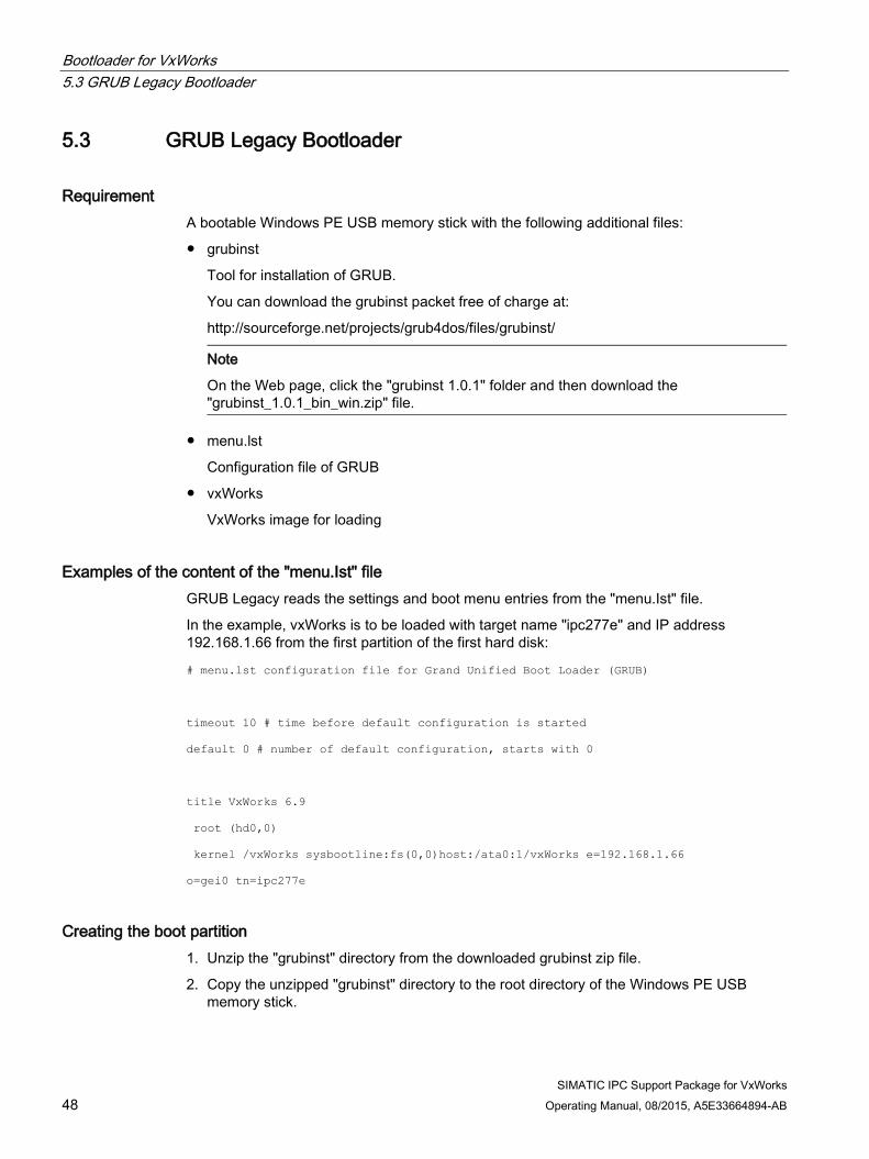
Examples of the content of the "menu.Ist" file GRUB Legacy reads the settings and boot menu entries from the "menu.Ist" file.
In the example, vxWorks is to be loaded with target name "ipc277e" and IP address 192.168.1.66 from the first partition of the first hard disk:
# menu.lst configuration file for Grand Unified Boot Loader (GRUB)
timeout 10 # time before default configuration is started
default 0 # number of default configuration, starts with 0
title VxWorks 6.9
root (hd0,0)
kernel /vxWorks sysbootline:fs(0,0)host:/ata0:1/vxWorks e=192.168.1.66
o=gei0 tn=ipc277e
Creating the boot partition 1. Unzip the "grubinst" directory from the downloaded grubinst zip file.
2. Copy the unzipped "grubinst" directory to the root directory of the Windows PE USB memory stick.

Bootloader for VxWorks 5.3 GRUB Legacy Bootloader
SIMATIC IPC Support Package for VxWorks Operating Manual, 08/2015, A5E33664894-AB 49
3. Copy the "menu.lst" and "vxWorks" files to the root directory of the Windows PE USB memory stick.
4. Insert the USB memory stick into your SIMATIC IPC and boot Windows PE from this USB memory stick.
5. Open the DOS command prompt and enter the following command:
X:\Tools> diskpart
6. Enter the following command in the "DiskPart" command line tool:
DISKPART> list disk
A list of data storage media is displayed:
Disk ### Status Size Free Dyn Gpt
Disk 0 Online 465 GB 1024 KB
Disk 1 Online 1907 MB 0 B
7. Select "Disk 0" from the list. The hard disk is Disk 0.
DISKPART> select disk 0
8. Ensure that the correct hard disk is selected in the list of data storage media.
You can recognize the selected data storage medium by the the character "*".
DISKPART> list disk
Disk ### Status Size Free Dyn Gpt
Disk 0 Online 465 GB 1024 KB
Disk 1 Online 1907 MB 0 B
9. Run the command to clean the hard disk.
DISKPART> clean
10. Create an active primary partition:
DISKPART> create partition primary size=2000
11. Select the first partition:
DISKPART> select partition 1
12. Mark the selected partition as active:
DISKPART> active
13. Format the partition as "FAT". This can take up to 2 minutes, depending on the size.
DISKPART> format fs=fat
100 percent completed
14. Assign the partition a drive letter:
DISKPART> assign letter=C
15. Close DiskPart:
DISKPART> exit

Bootloader for VxWorks 5.4 GRUB Bootloader and Windows
SIMATIC IPC Support Package for VxWorks 50 Operating Manual, 08/2015, A5E33664894-AB
Installing GRUB
1. Change to the "grubinst" folder on the USB memory stick
2. Run the following command. In the example described here, the start partition is on the hard disk (hd0):
grubinst (hd0)
3. Copy the "grldr" file to the root of the boot partition you have just created ("c.").
copy grldr c:
4. Change back to the root of the USB memory stick, and copy the GRUB configuration file to the hard disk.
copy menu.lst c:
5. Copy the VxWorks image to the hard disk.
copy vxWorks c:
6. Remove the USB memory stick from your target system.
5.4 GRUB Bootloader and Windows This section describes how to add a bootable VxWorks to an existing Windows 7 installation using GRUB. Grub2Win is used in the following for installation of GRUB 2. This tool does not change the MBR (Master Boot Record). Rather, it inserts GRUB as an option in the Windows 7 bootloader.
The GRUB bootloader loads the VxWorks image that is stored on the bulk storage device (AHCI, USB).
Requirements ● You have downloaded the Grub2Win tool from the Internet
(http://sourceforge.net/projects/grub2win/) and saved it in a temporary directory.
● The VxWorks image is stored on a partition of the hard disk.
Installing GRUB If required, carry out the installation as administrator.
1. Start Windows Explorer.
2. Unzip Grub2Win and copy the "grub2" directory to the Windows system drive (normally C:\).
3. Change to the "grub2" directory you have just copied.
Bootloader for VxWorks 5.4 GRUB Bootloader and Windows
SIMATIC IPC Support Package for VxWorks Operating Manual, 08/2015, A5E33664894-AB 51
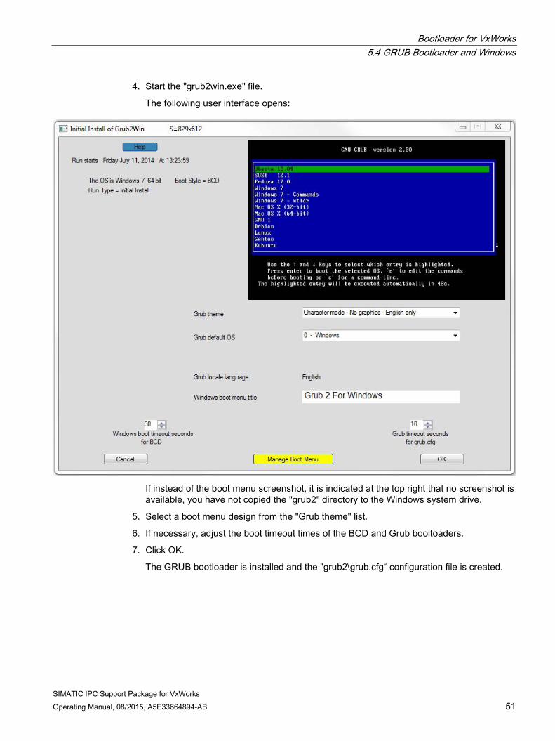
4. Start the "grub2win.exe" file.
The following user interface opens:
If instead of the boot menu screenshot, it is indicated at the top right that no screenshot is available, you have not copied the "grub2" directory to the Windows system drive.
5. Select a boot menu design from the "Grub theme" list.
6. If necessary, adjust the boot timeout times of the BCD and Grub booltoaders.
7. Click OK.
The GRUB bootloader is installed and the "grub2\grub.cfg“ configuration file is created.

Bootloader for VxWorks 5.4 GRUB Bootloader and Windows
SIMATIC IPC Support Package for VxWorks 52 Operating Manual, 08/2015, A5E33664894-AB
Adding VxWorks to GRUB 1. Open the "grub.cfg" grub configuration file with a text editor (e.g. WordPad).
2. Insert the following entry in the "grub2win-user-section“:
# start-grub2win-user-section
********************************************************
#
#
menuentry "VxWorks" {
multiboot (hd0,msdos5)/vxWorks sysbootline:fs(0,0)host:/ata0:1/vxWorks
e=192.168.1.62 o=gei0 tn=ipc427d
}
The entry "(hd0,msdos5)/vxWorks" specifies the storage location of the VxWorks image. This must be adapted to your system.
In this example, the VxWorks image is located in the "msdos5" partition on hard disk "hd0". You can look up the hard disk number and arrangement of the partitions, for example, under Computer Management > Disk Management.
You also have to adapt the VxWorks-sysbootline to your requirements.
3. In the Grub bootloader, Windows is preselected by default and is started after the specified timeout period. If you want to preselect VxWorks instead, restart the "grub2win.exe" program and select the "VxWorks" entry under "Grub default OS".
Grub is now installed with an entry for VxWorks.
Changing the BCD default entry (optional) At system start, the Windows BCD bootloader is loaded first. It now displays the following entries:
● Windows 7:
With the preselected entry "Windows 7", Windows is started directly.
● GRUB For Windows:
With this entry, the Grub bootloader installed in the previous steps is started.

Bootloader for VxWorks 5.4 GRUB Bootloader and Windows
SIMATIC IPC Support Package for VxWorks Operating Manual, 08/2015, A5E33664894-AB 53
If you prefer that Grub is preselected in the BCD and automatically started, perform the following steps: 1. Open a command prompt in Windows as Administrator.
2. Enter the following command:
C:\windows\system32>bcdedit /enum
The entries of the BCD are displayed:
Windows Boot Manager identifier {bootmgr}
device partition=X:
description Windows Boot Manager
locale de-De
inherit {globalsettings}
default {current}
resumeobject {52024e9a-2855-11e2-b655-f29c655de332}
displayorder {current}
{b9b88c23-066a-11e4-9cf0-001b1b414eae}
toolsdisplayorder {memdiag}
timeout 5
Windows Boot Loader
identifier {current}
device partition=C:
path \windows\system32\winload.exe
description Windows7
locale de-De
inherit {bootloadersettings}
recoverysequence {52024e9c-2855-11e2-b655-f29c655de332}
recoveryenabled Yes
osdevice partition=C:
systemroot \windows
resumeobject {52024e9a-2855-11e2-b655-f29c655de332}
nx OptIn
Real Mode Boot Sector
identifier {b9b88c23-066a-11e4-9cf0-001b1b414eae}
device partition=C:
path \grub2\winloader\grub2.boot
description Grub 2 For Windows

Bootloader for VxWorks 5.4 GRUB Bootloader and Windows
SIMATIC IPC Support Package for VxWorks 54 Operating Manual, 08/2015, A5E33664894-AB
3. Copy the identifier of the Grub entry.
4. Set "GRUB 2" as default.
C:\windows\system32>bcdedit /default {b9b88c23-066a-11e4-9cf0-001b1b414eae}
The second parameter of the command is the identifier of the Grub entry copied in the previous step.
Grub is now preselected at system start.
Grub cannot find the VxWorks image If Grub cannot find the VxWorks image on the hard disk, it is possible that the hard disk number or partition number specified in the "grub.cfg" file is incorrect.
Check the path of your VxWorks image as follows:
1. Change to command line mode in Grub with 'c'.
2. Display all available partitions with the "Is" command.
grub> ls
(hd0) (hd0,msdos5) (hd0,msdos2) (hd0,msdos1)
3. Check the partition where the VxWorks is located. You will recognize the correct partition by the file system type and the name.
grub> ls (hd0,msdos5)
Partition hd0,msdos5: Filesystem type fat - Label ‘VXWORKS‘ …
4. When you have found the correct partition identifier, change the entry in the "grub.cfg" file in Windows accordingly.

SIMATIC IPC Support Package for VxWorks Operating Manual, 08/2015, A5E33664894-AB 55
Creating a downloadable kernel module 6
1. Open Wind River Workbench.
2. Select "File > New > Project".
3. In the following dialog window, open the "VxWorks 6.x" folder in list box and then select the option "VxWorks Downloadable Kernel Module Project".
4. Click "Next".
5. Enter the name of the kernel module project for "Project name" and click "Next".
6. Skip the next dialogs, "Project", "Built Defaults" and "Build Support".
7. In the "Build Spec" dialog, disable all entries except "NEHALEMgnu_SMP".
8. Select the "NEHALEMgnu_SMP" option for "Active build spec".
9. Click "Next".
Creating a downloadable kernel module
SIMATIC IPC Support Package for VxWorks 56 Operating Manual, 08/2015, A5E33664894-AB
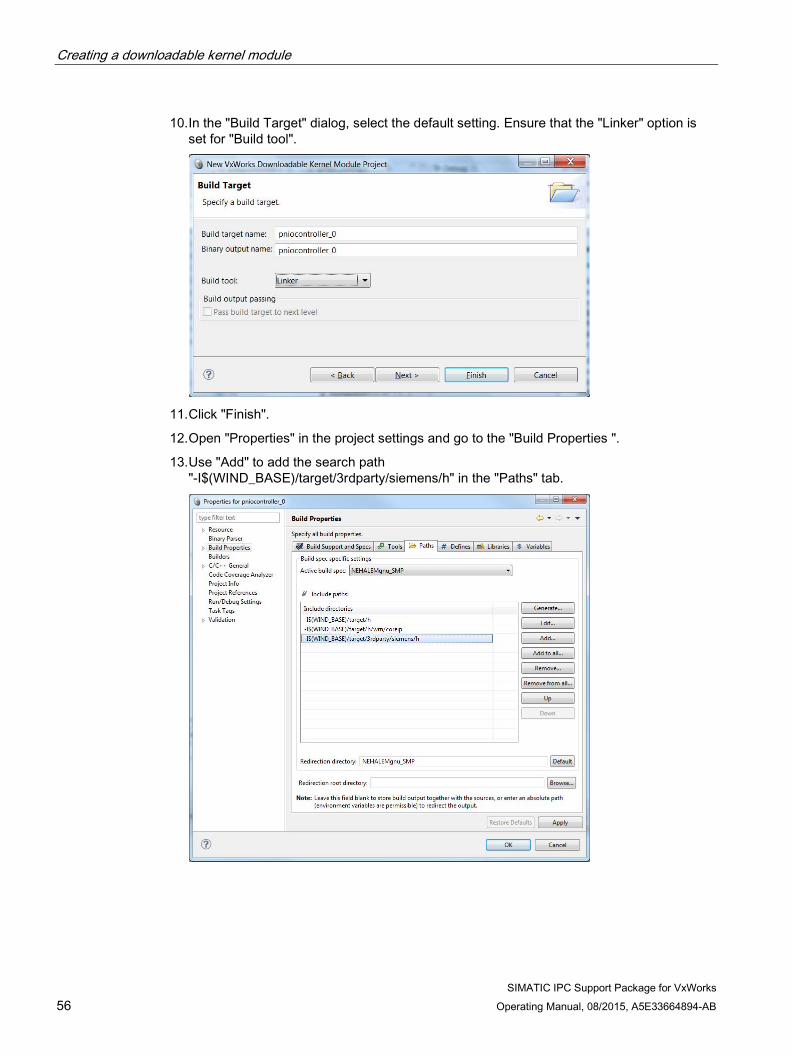
10. In the "Build Target" dialog, select the default setting. Ensure that the "Linker" option is set for "Build tool".
11. Click "Finish".
12. Open "Properties" in the project settings and go to the "Build Properties ".
13. Use "Add" to add the search path "-I$(WIND_BASE)/target/3rdparty/siemens/h" in the "Paths" tab.

Creating a downloadable kernel module
SIMATIC IPC Support Package for VxWorks Operating Manual, 08/2015, A5E33664894-AB 57
14. If you use "//" as the comment characters in your C source code, delete the "- ansi" switch from the" Tool Flags" in the "Tools" tab.
15. Add your source code and compile the kernel module by clicking "Project > Build Project".
When the "Build" dialog below is displayed for compiling the application and you have added all the include paths to the project settings, click "Continue".
Result The downloadable kernel module is created.
The name of the generated downloadable file in this example is "pniocontroller_0.out". This file can be loaded to the target system via Workbench or via the file system.

Creating a downloadable kernel module
SIMATIC IPC Support Package for VxWorks 58 Operating Manual, 08/2015, A5E33664894-AB

SIMATIC IPC Support Package for VxWorks Operating Manual, 08/2015, A5E33664894-AB 59
Creating a Real Time Process (RTP) application 7
You create a Real Time Process application in the same way as a downloadable kernel module.
● Select the "VxWorks Real Time Process Project" option as the project type.
● In the "Build Specs" dialog, select the "NEHALEMgnu_RTP" option.
Note
The name of the generated file has the extension ".vxe".
See also Creating a downloadable kernel module (Page 55)
Using PROFINET calls in the Real Time Process (user mode) (Page 70)
Using PROFINET calls in the Real Time Process (user mode) (Page 78)
Using hardware-dependent functions in the Real Time Process (user mode) (Page 86)

Creating a Real Time Process (RTP) application
SIMATIC IPC Support Package for VxWorks 60 Operating Manual, 08/2015, A5E33664894-AB
SIMATIC IPC Support Package for VxWorks Operating Manual, 08/2015, A5E33664894-AB 61
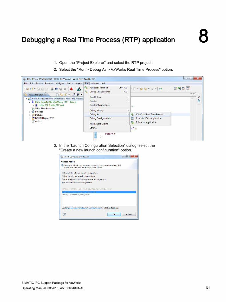
Debugging a Real Time Process (RTP) application 8
1. Open the "Project Explorer" and select the RTP project.
2. Select the "Run > Debug As > VxWorks Real Time Process" option.
3. In the "Launch Configuration Selection" dialog, select the
"Create a new launch configuration" option.

Debugging a Real Time Process (RTP) application
SIMATIC IPC Support Package for VxWorks 62 Operating Manual, 08/2015, A5E33664894-AB
4. In the "Launch Context" tab, select the correct target-server connection for your target.
Make sure that the path under the "Exec Path on Target" option in the "General" area starts with "/tgtsvr/" .
5. Click "Debug".
Result The RTP program is transferred and debugging starts.

Debugging a Real Time Process (RTP) application
SIMATIC IPC Support Package for VxWorks Operating Manual, 08/2015, A5E33664894-AB 63
If the debug connection fails If the path for "Exec Path on Target" starts with "host:" (see step 4 above) and establishment of a debug connection fails, proceed as follows:
1. Open the "Remote Systems" view, right-click on your target connection and open the "Properties" dialog.
The target server settings are open.
2. Open the "Object Path Mappings" tab.
Ensure that "/tgtsvr/" is the first entry in the "Pathname prefix mappings" area. Use the buttons to the right of the list to sort the list entries.
3. In the "Debug Configuration" dialog, ensure that the path for the "Exec Path on Target"
option starts with "/tgtsvr/".

Debugging a Real Time Process (RTP) application
SIMATIC IPC Support Package for VxWorks 64 Operating Manual, 08/2015, A5E33664894-AB
SIMATIC IPC Support Package for VxWorks Operating Manual, 08/2015, A5E33664894-AB 65
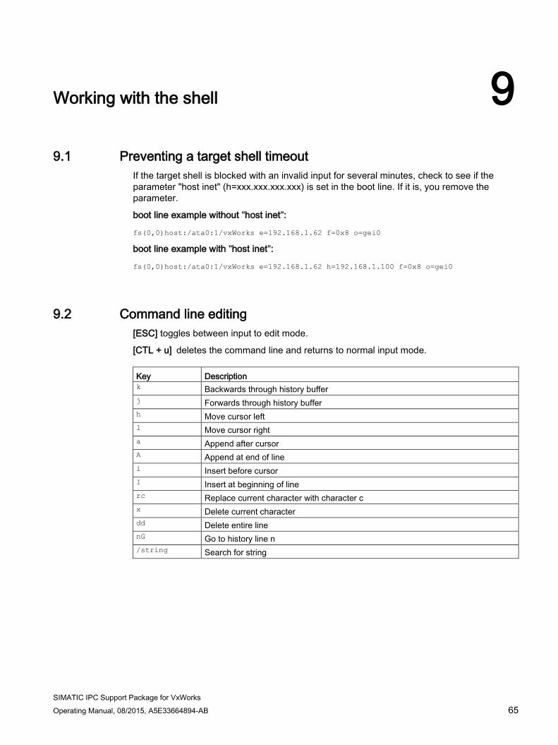
Working with the shell 9 9.1 Preventing a target shell timeout
If the target shell is blocked with an invalid input for several minutes, check to see if the parameter "host inet" (h=xxx.xxx.xxx.xxx) is set in the boot line. If it is, you remove the parameter.
boot line example without "host inet":
fs(0,0)host:/ata0:1/vxWorks e=192.168.1.62 f=0x8 o=gei0
boot line example with "host inet":
fs(0,0)host:/ata0:1/vxWorks e=192.168.1.62 h=192.168.1.100 f=0x8 o=gei0
9.2 Command line editing [ESC] toggles between input to edit mode.
[CTL + u] deletes the command line and returns to normal input mode. Key Description k Backwards through history buffer j Forwards through history buffer h Move cursor left l Move cursor right a Append after cursor A Append at end of line i Insert before cursor I Insert at beginning of line rc Replace current character with character c x Delete current character dd Delete entire line nG Go to history line n /string Search for string

Working with the shell 9.2 Command line editing
SIMATIC IPC Support Package for VxWorks 66 Operating Manual, 08/2015, A5E33664894-AB

SIMATIC IPC Support Package for VxWorks Operating Manual, 08/2015, A5E33664894-AB 67
PROFINET driver 10 10.1 PROFINET functions
PROFINET functions The following PROFINET functions are available:
● Controller functions
● Device functions
● Product-specific functions
Only one PROFINET interface is supported. The API interface is not reentrant, i.e. only one PROFINET function can be called at a time.
Operating modes The IO-Base user programming interface supports the following modes:
● RT (Real Time)
● IRT (Isochronous Real Time)
You can find a detailed description of each function in the programming manual "SIMATIC NET PROFINET IO-Base User Programming Interface" (PGH_IO-Base_0.pdf file), which is located in the directory "<WIND_BASE>\target\3rdparty\siemens\docs".
Applications can run in kernel mode (Downloadable Kernel Module project, DKM) or in user mode (Real Time Process project, RTP).
PROFINET driver The following two PROFINET drivers are available:
● CP 16xx driver for PROFINET
The CP 16xx driver for PROFINET supports the CP 1616 onboard and is referred to as the CP 16xx driver in the following. Controller functionality and device functionality are available in RT and IRT operating modes. The required PROFINET firmware is included in the product package.
● PN driver for PROFINET
The PN driver uses an Ethernet interface of the IPC for the PROFINET protocol. Only PROFINET controller functionality is available in the RT operating mode in this case.
Note that you can integrate only one of the two PROFINET drivers.
PROFINET driver 10.2 PROFINET driver
SIMATIC IPC Support Package for VxWorks 68 Operating Manual, 08/2015, A5E33664894-AB
10.2 PROFINET driver
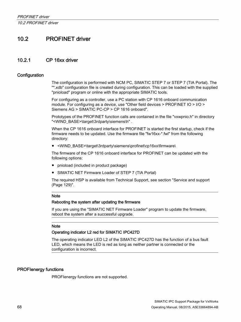
10.2.1 CP 16xx driver
Configuration The configuration is performed with NCM PC, SIMATIC STEP 7 or STEP 7 (TIA Portal). The "*.xdb" configuration file is created during configuration. This can be loaded with the supplied "pnioload" program or online with the appropriate SIMATIC tools.
For configuring as a controller, use a PC station with CP 1616 onboard communication module. For configuring as a device, use "Other field devices > PROFINET IO > I/O > Siemens AG > SIMATIC PC-CP > CP 1616 onboard".
Prototypes of the PROFINET function calls are contained in the file "vxwpnio.h" in directory "<WIND_BASE>\target\3rdparty\siemens\h" .
When the CP 1616 onboard interface for PROFINET is started the first startup, check if the firmware needs to be updated. Use the firmware file "fw16xx-*.fwl" from the following directory:
● <WIND_BASE>\target\3rdparty\siemens\profinet\cp16xx\firmware\
The firmware of the CP 1616 onboard interface for PROFINET can be updated with the following options:
● pnioload (included in product package)
● SIMATIC NET Firmware Loader of STEP 7 (TIA Portal)
The required HSP is available from Technical Support, see section "Service and support (Page 129)".
Note Rebooting the system after updating the firmware
If you are using the "SIMATIC NET Firmware Loader" program to update the firmware, reboot the system after a successful upgrade.
Note Operating indicator L2 red for SIMATIC IPC427D
The operating indicator LED L2 of the SIMATIC IPC427D has the function of a bus fault LED, which means the LED is red as long as neither partner is connected or the configuration is incorrect.
PROFIenergy functions PROFIenergy functions are not supported.

PROFINET driver 10.3 IO-Base interface
SIMATIC IPC Support Package for VxWorks Operating Manual, 08/2015, A5E33664894-AB 69
10.2.2 PN driver
Configuration The PN driver supports only the second network connection, "X2P1", of the SIMATIC IPC.
No network driver from VxWorks needs to be configured for the network connection used by the PN driver.
The configuration is performed in STEP 7 (TIA Portal) V13 with HSP0074. For configuring, use a PC system with PN driver communication module. The "Real-time" interface submodule must be configured as the PROFINET interface of the PN driver station. The "*.xml" configuration file is created during configuration. It is evaluated only when the driver starts. No change to the configuration is possible during operation.
The required HSP is available from Support, see section "Service and support (Page 129)".
PROFIenergy functions PROFIenergy functions are not supported.
10.3 IO-Base interface You can find a detailed description of the IO-Base interface in the programming manual "SIMATIC NET PROFINET IO-Base User Programming Interface" ("PGH_IO-Base_0.pdf" file), which is located in the directory "<WIND_BASE>\target\3rdparty\siemens\docs".
Note
The "SERV_CP_set_type_of_station" call is not supported.
10.4 Using PROFINET calls in the downloadable kernel module (DKM) All PROFINET calls can also be used in a downloadable kernel module (DKM). Use the supplied "vxwpnio.h" header file for this. No library needs to be included.

PROFINET driver 10.5 Using PROFINET calls in the Real Time Process (user mode)
SIMATIC IPC Support Package for VxWorks 70 Operating Manual, 08/2015, A5E33664894-AB
10.5 Using PROFINET calls in the Real Time Process (user mode) You can use all PROFINET calls in a Real Time Process (RTP). Use the supplied "vxwpnio.h" header file for this.
If you are using the CP 16xx driver, the supplied "libcp16xx_rtp.a" library must be integrated; if you are using the PN driver, the supplied "libpn_rtp.a" library from directory <WIND_BASE>\target\3rdparty\siemens\lib must be integrated.
In RTP mode, almost all of the driver code is executed on user level (privilege level 3).
Syscall group 51 is used for communication between user mode and kernel mode. You can find the information on how this value is configured in the section "Configuring the PROFINET driver (Page 72)".

PROFINET driver 10.6 Messages of the PROFINET driver
SIMATIC IPC Support Package for VxWorks Operating Manual, 08/2015, A5E33664894-AB 71
10.6 Messages of the PROFINET driver
Messages on the system console VxWorks PROFINET Driver for CP 16xx V1.0.x
(C) Copyright 2014, Siemens AG. All rights reserved.
* Number of boards: 1
* CP1616 IRQ:19, MAC: 00.01.02.03.04.05
or:
VxWorks PROFINET PN (RT) Driver for standard LAN controller V1.0.x
(C) Copyright 2014, Siemens AG. All rights reserved.
Format of the error messages The PROFINET driver sends warnings and error messages to the system console. These warnings and error messages have the following format:
*** cp16xx: <text>
or:
*** pn: <text>
Note
If an error occurs, contact Technical Support, see section "Service and support (Page 129)".
Procedure If the PROFINET driver is terminated due to an error, reboot the system.

PROFINET driver 10.7 Configuring the PROFINET driver
SIMATIC IPC Support Package for VxWorks 72 Operating Manual, 08/2015, A5E33664894-AB
10.7 Configuring the PROFINET driver
10.7.1 Configuring the CP 16xx driver Base priority (default: 0) of the tasks and the syscall group (default: 51) are changed in the "Kernel Configuration" under the "INCLUDE_PROFINET_CP16XX" component.
The base priority is configured with the parameter "PNIO_CP16XX_PRIORITY".
The default base priority is "0", i.e. the highest priority. The priority may assume a value between 0 and 150.
The priorities of the tasks created by the PROFINET driver depend on the base priority.
The following table indicates the tasks that the PROFINET driver initiates and which the priorities assigned to these tasks. Task name Description Priority PN_DPR0 Task for reading the data from the DPR of the module Base priority + 99 PN_CMD Task for processing asynchronous commands, such as
Reset modules Base priority + 99
PN_TIMER_TASK Auxiliary task for the firmware watchdog Base priority PN_SYNCH0_<x> Task for processing the SYNCH events of the module Base priority + 99 PN_ALARM0_<x> Task for processing the ALARM events of the module Base priority + 99 PN_MODIND0_<x> Task for processing the MODIND events of the module Base priority + 99 PN_DATAREC0_<x> Task for processing the DATAREC events of the module Base priority + 99 PN_WD0_<x> Task for processing the WATCHDOG events of the
module Base priority
PN_STARTOP0_<x> Task for processing the STARTOP events of the module Base priority + 1 PN_OPFAULT0_<x> Task for processing the OPFAULT events of the module Base priority + 1 PN_NCYCLE0_<x> Task for processing the NEWCYCLE events of the module Base priority + 1 PN_CPINFO Task for processing SERV_CP_info-calls Base priority + 99 PN_READDOWN Task for loading firmware and resetting the module Base priority + 99

PROFINET driver 10.7 Configuring the PROFINET driver
SIMATIC IPC Support Package for VxWorks Operating Manual, 08/2015, A5E33664894-AB 73
Note
The following tasks are created immediately after the start of the PROFINET driver: • PN_DPR0 • PN_CMD • PN_TIMER_TASK
All other tasks are only created by a PROFINET application when the corresponding events are used.
Tasks with a "_ <x>" in the name are bound to a controller and/or device instance and can therefore occur more than once.
<x> here stands for a digit between 0 and 9.
Syscall group 51 is used for communication between user mode and kernel mode. If group 51 is already in use, this value can be changed with the "PNIO_CP16XX_SYSCALLGROUP" parameter.
Syscall groups can be shown as follows:
-> syscallShow Group Name GroupNo NumRtns Rtn Tbl Addr -------------------- ------- ------- ------------------ STANDARDGroup 8 64 0x00000000006772a0 PROFIBUS CP5622 13 34 0x00000000044f8d90 PROFINET CP16XX 51 8 0x00000000044f8e90 When the syscall-group is changed, the "syscallGroup_pnio" variable in the application must be preset with the new value.
extern unsigned int syscallGroup_pnio;
…
syscallGroup_pnio = 51; //new value

PROFINET driver 10.7 Configuring the PROFINET driver
SIMATIC IPC Support Package for VxWorks 74 Operating Manual, 08/2015, A5E33664894-AB
10.7.2 Configuring the PN driver The path for the configuration file (default: "/ata0:1/Station_1.PN Driver_1.PNDriverConfiguration.xml"), the priority of the interrupt task (default: 0) and the syscall group (default: 51) can be changed in the "Kernel Configuration" under the "INCLUDE_PROFINET_LAN" component.
SIMATIC IPCs typically have two Ethernet interfaces.
VxWorks uses the first Ethernet interface that is found on the PCI bus, if IFCONFIG_1 is set.
The PN driver uses the second Ethernet port.
When the PN driver is used, the second Ethernet port may not be used by VxWorks, i.e. IFCONFIG_2 may not be set.
Syscall group 51 is used for communication between user mode and kernel mode. If group 51 is already in use, this value can be changed with the "PN_SYSCALLGROUP" parameter.
The syscall groups can be displayed as follows:
-> syscallShow Group Name GroupNo NumRtns Rtn Tbl Addr -------------------- ------- ------- ------------------ STANDARDGroup 8 64 0x00000000006772a0 PROFIBUS CP5622 13 34 0x00000000044f8d90 PROFINET PN 51 8 0x00000000044f8e90 When the syscall-group is changed, the "syscallGroup_pn" variable in the application must be preset with the new value.
extern unsigned int syscallGroup_pn;
…
syscallGroup_pn = 51; //new value

SIMATIC IPC Support Package for VxWorks Operating Manual, 08/2015, A5E33664894-AB 75
PROFIBUS driver 11 11.1 PROFIBUS functions
The PROFIBUS driver supports the PROFIBUS connection of the SIMATIC IPC. The PROFIBUS connection includes a processor on which the firmware "fw_5612.bin" runs. The communication to the user is made via shared memory.
Master functionality according to PROFIBUS DP Master Class 1, "active" slave functionality and the PROFIBUS protocol "DP-V0" are supported.
The driver provides the so-called DP-Base interface as the API interface.
Only one PROFIBUS interface is supported. The API interface is not reentrant, i.e. only one PROFIBUS function can be called at a time.
Applications can run in both in kernel mode (DKM) as well as in user mode (Real Time Process). Prototypes of the PROFIBUS function calls are contained in the file "vxwdp.h".
11.2 DP-Base interface
11.2.1 Programming manual for DP-Base interface You can find a detailed description of the DP-Base interface in the programming manual "SIMATIC NET PROFINET DP-Base Programming Interface for CP 5613/CP 5614" ("mn_dp_base_api_0.pdf" file), which is located in directory "<WIND_BASE>\target\3rdparty\siemens\docs".
11.2.2 Sending DP slave data (update of the information in the programming manual) The information regarding sending DP slave data described in the programming manual for the DP-Base interface has changed; see section 5.3.13 "Sending DP slave data" in "Programming manual for DP-Base interface (Page 75)".
The sent data of the DP slave cannot be transferred to the output image of the slave module via memory access to the DP-RAM. Instead, the "DPS_write ()" function described below must be used.
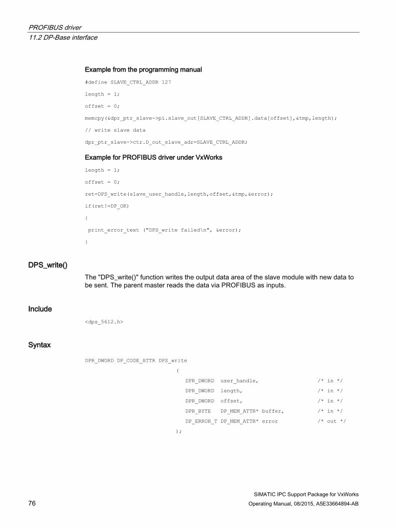
PROFIBUS driver 11.2 DP-Base interface
SIMATIC IPC Support Package for VxWorks 76 Operating Manual, 08/2015, A5E33664894-AB
Example from the programming manual
#define SLAVE_CTRL_ADDR 127
length = 1;
offset = 0;
memcpy(&dpr_ptr_slave->pi.slave_out[SLAVE_CTRL_ADDR].data[offset],&tmp,length);
// write slave data
dpr_ptr_slave->ctr.D_out_slave_adr=SLAVE_CTRL_ADDR;
Example for PROFIBUS driver under VxWorks
length = 1;
offset = 0;
ret=DPS_write(slave_user_handle,length,offset,&tmp,&error);
if(ret!=DP_OK)
{
print_error_text ("DPS_write failed\n", &error);
}
DPS_write() The "DPS_write()" function writes the output data area of the slave module with new data to be sent. The parent master reads the data via PROFIBUS as inputs.
Include <dps_5612.h>
Syntax DPR_DWORD DP_CODE_ATTR DPS_write ( DPR_DWORD user_handle, /* in */
DPR_DWORD length, /* in */
DPR_DWORD offset, /* in */
DPR_BYTE DP_MEM_ATTR* buffer, /* in */
DP_ERROR_T DP_MEM_ATTR* error /* out */
);

PROFIBUS driver 11.3 Using PROFIBUS calls in the downloadable kernel module (DKM)
SIMATIC IPC Support Package for VxWorks Operating Manual, 08/2015, A5E33664894-AB 77
Parameters Parameter Meaning user_handle User handle that was assigned when calling DPS_open length Length of the data to be sent offset Offset of the data buffer Pointer to the data to be sent error Address of a structure of type DP_ERROR_T provided by the DP user program.
If an error occurs, the structure contains details for troubleshooting (see DP-Base description).
Return value Value Meaning DP_OK Function successfully executed DP_ERROR_REQ_PAR and error->error_code == DP_RET_PAR_USR_HNDL
The user_handle parameter is invalid
DP_ERROR_REQ_PAR and error->error_code == DPS_RET_PAR_STATE
The parameter buffer is invalid
DP_ERROR_CI and error->error_code == "other"
Unsuccessful completion of function
11.3 Using PROFIBUS calls in the downloadable kernel module (DKM) All PROFIBUS calls can be used in a downloadable kernel module (DKM). Use the supplied "vxwdp.h" header file for this. No library needs to be included.

PROFIBUS driver 11.4 Using PROFINET calls in the Real Time Process (user mode)
SIMATIC IPC Support Package for VxWorks 78 Operating Manual, 08/2015, A5E33664894-AB
11.4 Using PROFINET calls in the Real Time Process (user mode) You can also use all PROFIBUS calls in a Real Time Process (RTP). Use the supplied "vxwdp.h" header file for this. No library needs to be included.
Since a maximum of 8 parameters are possible in the transition from user mode to kernel mode, the following parameters are not evaluated with the "DPS_open" call: Parameter Set value cp_name "CP5612_1" addr_change 0 baud_rate DPS_BD_AUTO_DETECT
Syscall group 13 is used for communication between user mode and kernel mode. You can find the information on how this value is configured in the section "Configuring PROFIBUS (Page 79)".
11.5 Messages of the PROFIBUS driver
Startup message of the driver VxWorks PROFIBUS DP Driver for CP 5622 V1.0.x
(C) Copyright 2014, Siemens AG. All rights reserved.
Format of the error messages The PROFIBUS driver sends warnings and error messages to the system console. These warnings and error messages have the following format:
*** cp5622: <text>
Note
If an error occurs, contact Technical Support, see section Service and support (Page 129).

PROFIBUS driver 11.6 Configuring PROFIBUS
SIMATIC IPC Support Package for VxWorks Operating Manual, 08/2015, A5E33664894-AB 79
11.6 Configuring PROFIBUS The path for the firmware file (default: "/ata0:1"), the priority of the interrupt task (default: "0") and the syscall group (default: "13") can be changed in the "Kernel Configuration" under the "INCLUDE_PROFIBUS_CP5622" component.
Syscall group 13 is used for communication between user mode and kernel mode.
If group 13 is already in use, this value can be changed with the "DP_CP5622_SYSCALLGROUP" parameter.
The syscall groups can be displayed as follows on the target system:
-> syscallShow Group Name GroupNo NumRtns Rtn Tbl Addr -------------------- ------- ------- ------------------ STANDARDGroup 8 64 0x00000000006772a0 PROFIBUS CP5622 13 34 0x00000000044f8d90 If the syscall group is changed, the "MY_OWN_SCG" define must also be changed accordingly in the "dp_rtp.h" file in directory "<WIND_BASE>\target\3rdparty\siemens\h".
Example:
#define MY_OWN_SCG 13
11.7 Creating a configuration A database containing basic information about the PROFIBUS configuration of the CP is required by the firmware for the operation of the PROFIBUS interface.
The firmware checks in slave mode the validity of the database and compares the actual configuration with the target configuration.
The following configuration tools are supported for the configuration of the PROFIBUS interface: Tool Restrictions/errors SIMATIC Manager STEP7 V5.5 (Service Pack 3, Hotfix 3) No restrictions STEP 7 (TIA-Portal) as of V13 No restrictions
A configuration for the CP 5613-A2 module must be used to enable the onboard interface for PROFIBUS (compatible with CP 5622) to export a configuration file.
You can find configuration examples in the following directory: <WIND_BASE>\target\3rdparty\siemens\examples

PROFIBUS driver 11.7 Creating a configuration
SIMATIC IPC Support Package for VxWorks 80 Operating Manual, 08/2015, A5E33664894-AB
11.7.1 Configuring with SIMATIC Manager STEP7
Configuring the master Configure the master as a SIMATIC PC station.
1. Open the hardware catalog and scroll to the corresponding processor. You can find it in the following directory:
SIMATIC PC Station->CP-PROFIBUS->CP 5613 A2->SW V7.1.2.
2. Add an application to the master. You can find it in the following directory:
SIMATIC PC Station->User_Application->Application.
Select version "SW V8.1.2" .
3. Select the "DP-Master" and "DPV0-compatible" settings for the CP5613A2 under "Properties->Operating mode".
4. Under "Properties->Operating mode", select the "Generate LDB file" option and assign the name and path.
A database (.ldb file) containing basic information about the PROFIBUS configuration of the processor is required for the operation as master.
5. Perform a "Save and Compile".
The .ldb file is created.
Note
The onboard Interface for PROFIBUS supports a maximum of 64 DP slaves.
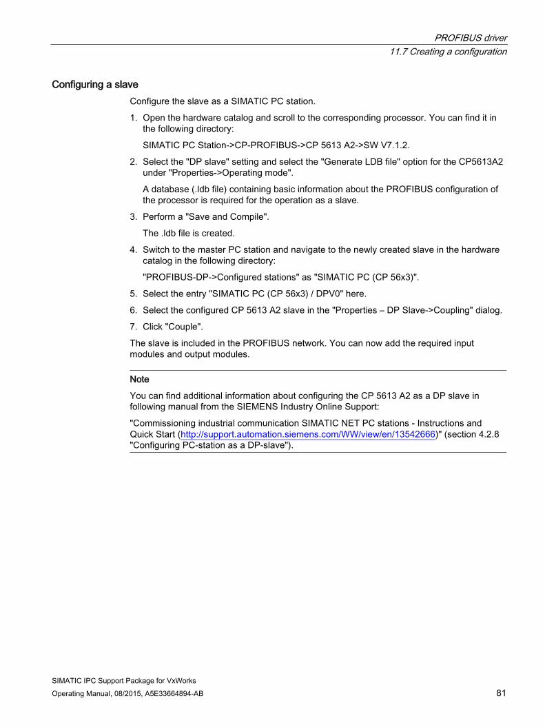
PROFIBUS driver 11.7 Creating a configuration
SIMATIC IPC Support Package for VxWorks Operating Manual, 08/2015, A5E33664894-AB 81
Configuring a slave Configure the slave as a SIMATIC PC station.
1. Open the hardware catalog and scroll to the corresponding processor. You can find it in the following directory:
SIMATIC PC Station->CP-PROFIBUS->CP 5613 A2->SW V7.1.2.
2. Select the "DP slave" setting and select the "Generate LDB file" option for the CP5613A2 under "Properties->Operating mode".
A database (.ldb file) containing basic information about the PROFIBUS configuration of the processor is required for the operation as a slave.
3. Perform a "Save and Compile".
The .ldb file is created.
4. Switch to the master PC station and navigate to the newly created slave in the hardware catalog in the following directory:
"PROFIBUS-DP->Configured stations" as "SIMATIC PC (CP 56x3)".
5. Select the entry "SIMATIC PC (CP 56x3) / DPV0" here.
6. Select the configured CP 5613 A2 slave in the "Properties – DP Slave->Coupling" dialog.
7. Click "Couple".
The slave is included in the PROFIBUS network. You can now add the required input modules and output modules.
Note
You can find additional information about configuring the CP 5613 A2 as a DP slave in following manual from the SIEMENS Industry Online Support:
"Commissioning industrial communication SIMATIC NET PC stations - Instructions and Quick Start (http://support.automation.siemens.com/WW/view/en/13542666)" (section 4.2.8 "Configuring PC-station as a DP-slave").

PROFIBUS driver 11.7 Creating a configuration
SIMATIC IPC Support Package for VxWorks 82 Operating Manual, 08/2015, A5E33664894-AB
11.7.2 Configuring with STEP 7 (TIA-Portal)
Configuring the master Configure the master as a SIMATIC PC station.
1. Switch to network view and open the device view of the master PC station.
2. Add the CP 5613 A2 to the PC station.
You can find the correct CP in the hardware catalog under "Communication modules->PROFIBUS->CP 5603, CP 5613 A2".
3. Select version ""SW V7.1.2 SP2".
4. Open the properties of the CP5613 A2 and select the "General" tab.
5. Under "PROFIBUS address", select a new PROFIBUS network and set the bus parameters of the master.
– Select the "DP master" setting as the "Mode".
– Select the setting "DPV0-compatible" for "DP mode".
6. Select the "Generate LDB file" option under "LDB configuration".
A database (.ldb file) containing basic information about the PROFIBUS configuration of the CP is required by the firmware for the operation as master.
7. Perform a "Compile" in the network view.
The .ldb file is created.
Note
The onboard Interface for PROFIBUS supports a maximum of 64 DP slaves.

PROFIBUS driver 11.7 Creating a configuration
SIMATIC IPC Support Package for VxWorks Operating Manual, 08/2015, A5E33664894-AB 83
Configuring a slave Configure the slave as a SIMATIC PC station.
1. Switch to network view and open the device view of the slave PC station.
2. Add the CP 5613 A2 to the PC station.
You can find the correct CP in the hardware catalog under "Communication modules->PROFIBUS->CP 5603, CP 5613 A2".
Select version ""SW V7.1.2 SP2".
3. Open the properties of the CP5613 A2 and select the "General" tab.
4. Under "PROFIBUS address", select a new PROFIBUS network and set the bus parameters for the slave.
– Select the "DP slave" setting as the "Mode".
– Select the setting "DPV0-compatible" for "DP mode".
– Select the PROFIBUS master for "Assigned DP master".
– If needed, add an input and output module under "Mode->I-slave communication".
5. Select the "Generate LDB file" option under "LDB configuration".
A database (.ldb file) containing basic information about the PROFIBUS configuration of the CP is required by the firmware for the operation as slave.
6. Perform a "Compile" in the network view.
The .ldb file is created.
Note
You can find additional information about configuring the CP 5613 A2 as a DP slave in following manual from the SIEMENS Industry Online Support:
"Commissioning industrial communication SIMATIC NET PC stations - Instructions and Quick Start (http://support.automation.siemens.com/WW/view/en/13542666)" (section 4.3.7 "Configuring PC station as a DP slave").

PROFIBUS driver 11.7 Creating a configuration
SIMATIC IPC Support Package for VxWorks 84 Operating Manual, 08/2015, A5E33664894-AB

SIMATIC IPC Support Package for VxWorks Operating Manual, 08/2015, A5E33664894-AB 85
Hardware-dependent functions 12
The following functions are available for accessing the hardware components of the IPC:
● Read CPU type
● Read temperature information
● Read fan status
● Read battery status
● Start and trigger watchdog
● Read and update operating hours counter
The operating hours counter records the operating time since commissioning.
In combination with a threshold value, it is possible to set a maintenance interval, for example.
● Setting user LEDs
● Using retentive memory as a RAMDISK
Some SIMATIC IPCs have a buffered retentive memory (NVRAM). The memory content is retained after the IPC is switched off. Refer to your order documents to determine whether your SIMATIC IPC is equipped with retentive memory and to find information about the size of this memory.
● Reading out SMART status
● Reading out and updating the real-time clock
12.1 Using hardware-dependent functions in the downloadable kernel module (DKM)
All calls of the hardware-dependent functions can also be used in a downloadable kernel module (DKM). Use the supplied "cpuex.h" header file for this. You do not need to include a library.

Hardware-dependent functions 12.2 Using hardware-dependent functions in the Real Time Process (user mode)
SIMATIC IPC Support Package for VxWorks 86 Operating Manual, 08/2015, A5E33664894-AB
12.2 Using hardware-dependent functions in the Real Time Process (user mode)
All calls of the hardware-dependent functions can also be used in a Real Time Process (user mode). Include the supplied "cpuex.h" header file for this. You do not need to include a library.
Syscall group 14 is used for communication between user mode and kernel mode. You can find the information on how this value is configured in the section "Configuring hardware-dependent functions (Page 87)".
12.3 Messages of the driver
Startup message of the driver using the example of IPC427D The following example applies to an IPC427D.
VxWorks SIMATIC IPC hardware dependent functions V1.0.x
(C) Copyright 2014, Siemens AG. All rights reserved.
SIMATIC IPC427D (type=13) detected
Error messages of the driver The driver sends warnings and error messages to the system console. These warnings and error messages have the following format:
*** cpuex: <text>
Note
If an error occurs, contact Technical Support, see section Service and support (Page 129).

Hardware-dependent functions 12.4 Configuring hardware-dependent functions
SIMATIC IPC Support Package for VxWorks Operating Manual, 08/2015, A5E33664894-AB 87
12.4 Configuring hardware-dependent functions Some parameters for the operating hours counter and the syscall group (default: 14) can be configured. These parameters are displayed in the configuration of the component when a VxWorks image is generated.
The following values are available for the configuration of the operating hours counter and the RAMDISK:
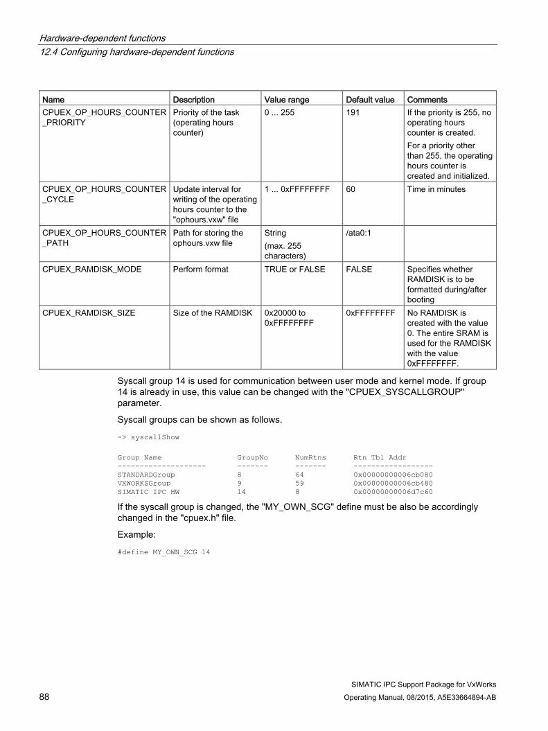
Hardware-dependent functions 12.4 Configuring hardware-dependent functions
SIMATIC IPC Support Package for VxWorks 88 Operating Manual, 08/2015, A5E33664894-AB
Name Description Value range Default value Comments CPUEX_OP_HOURS_COUNTER_PRIORITY
Priority of the task (operating hours counter)
0 ... 255 191 If the priority is 255, no operating hours counter is created. For a priority other than 255, the operating hours counter is created and initialized.
CPUEX_OP_HOURS_COUNTER_CYCLE
Update interval for writing of the operating hours counter to the "ophours.vxw" file
1 ... 0xFFFFFFFF 60 Time in minutes
CPUEX_OP_HOURS_COUNTER_PATH
Path for storing the ophours.vxw file
String (max. 255 characters)
/ata0:1
CPUEX_RAMDISK_MODE Perform format TRUE or FALSE FALSE Specifies whether RAMDISK is to be formatted during/after booting
CPUEX_RAMDISK_SIZE Size of the RAMDISK 0x20000 to 0xFFFFFFFF
0xFFFFFFFF No RAMDISK is created with the value 0. The entire SRAM is used for the RAMDISK with the value 0xFFFFFFFF.
Syscall group 14 is used for communication between user mode and kernel mode. If group 14 is already in use, this value can be changed with the "CPUEX_SYSCALLGROUP" parameter.
Syscall groups can be shown as follows.
-> syscallShow Group Name GroupNo NumRtns Rtn Tbl Addr -------------------- ------- ------- ------------------ STANDARDGroup 8 64 0x00000000006cb080 VXWORKSGroup 9 59 0x00000000006cb480 SIMATIC IPC HW 14 8 0x00000000006d7c60 If the syscall group is changed, the "MY_OWN_SCG" define must be also be accordingly changed in the "cpuex.h" file.
Example:
#define MY_OWN_SCG 14

Hardware-dependent functions 12.5 Access functions for hardware-dependent functions
SIMATIC IPC Support Package for VxWorks Operating Manual, 08/2015, A5E33664894-AB 89
Using retentive memory as a RAMDISK The retentive memory can be used as a RAMDISK. The size of the utilized memory is set with the configuration parameter CPUEX_RAMDISK_SIZE. If the RAMDISK is configured with a size > 0 during parameter assignment, it is given the drive name "/ram:0". If the RAMDISK has not yet been formatted, formatting is done automatically. Formatting after booting can also be forced with the configuration parameter "CPUEX_RAMDISK_MODE".
12.5 Access functions for hardware-dependent functions The following access functions are available: Function Description GetCPUTypeDMI() Determine the type of CPU used from DMI information ReadTemperature() Read the various temperature sensors in the SIMATIC IPC ReadFanStatus() Read the fan status ReadBatteryStatus() Read the battery status SetOpHoursCounter() Set the threshold for the operating hours counter GetOpHoursCounter() Read the operating hours counter value and the threshold value UpdateOpHoursCounter() Update the operating hours counter StartWatchdog() Start the hardware watchdog TriggerWatchdog() Trigger the hardware watchdog SetUserLED() Set user LED ResetUserLED() Reset user LED GetSMARTStatus() Read the S.M.A.R.T. status of a data storage medium GetCMOSDateTime() Read the real-time clock SetCMOSDateTime() Set the real-time clock
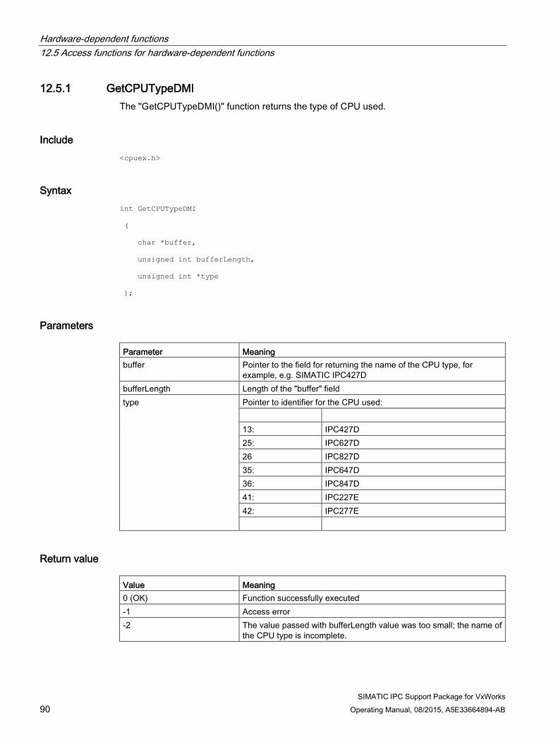
Hardware-dependent functions 12.5 Access functions for hardware-dependent functions
SIMATIC IPC Support Package for VxWorks 90 Operating Manual, 08/2015, A5E33664894-AB
12.5.1 GetCPUTypeDMI The "GetCPUTypeDMI()" function returns the type of CPU used.
Include <cpuex.h>
Syntax int GetCPUTypeDMI
(
char *buffer,
unsigned int bufferLength,
unsigned int *type
);
Parameters Parameter Meaning buffer Pointer to the field for returning the name of the CPU type, for
example, e.g. SIMATIC IPC427D bufferLength Length of the "buffer" field type Pointer to identifier for the CPU used:
13: IPC427D 25: IPC627D 26 IPC827D 35: IPC647D 36: IPC847D 41: IPC227E 42: IPC277E
Return value Value Meaning 0 (OK) Function successfully executed -1 Access error -2 The value passed with bufferLength value was too small; the name of
the CPU type is incomplete.

Hardware-dependent functions 12.5 Access functions for hardware-dependent functions
SIMATIC IPC Support Package for VxWorks Operating Manual, 08/2015, A5E33664894-AB 91
12.5.2 ReadTemperature The "ReadTemperature()" function reads the temperature of a specific sensor of the SIMATIC IPC depending on the "type" parameter.
The user can use this function, for example, to regularly read the temperature from a task and intervene when a certain temperature limit is reached.
Include <cpuex.h>
Syntax int ReadTemperature
(
unsigned int type,
unsigned char *buffer
);
Parameters Parameter Meaning type TEMPERATURE_CPU Temperature of the CPU
TEMPERATURE_MAINBOARD Temperature of the motherboard TEMPERATURE_MEMORY Temperature of the memory TEMPERATURE_POWER_SUPPLY Temperature of the power unit TEMPERATURE_CHASSIS Temperature of the enclosure
buffer Read temperature value in degrees Celsius

Hardware-dependent functions 12.5 Access functions for hardware-dependent functions
SIMATIC IPC Support Package for VxWorks 92 Operating Manual, 08/2015, A5E33664894-AB
Return value Value Meaning 0 (OK) Function successfully executed -1 Call is not supported for this CPU -2 Hardware fault, e.g., read error on system management bus (SMB) -3 This temperature sensor is not available for the CPU used
SIMATIC IPCs have the following temperature sensors: Device Temperature sensors IPC627D IPC647D IPC827D IPC847D
CPU, enclosure, memory, motherboard
IPC227E IPC277E IPC427D
CPU, memory, motherboard
Programming example unsigned char buffer;
int ret = ReadTemperature (TEMPERATURE_CPU, &buffer );
if (ret == OK) {
if (buffer >= 0x80) {
printf( "CPU Temperatur = -%u °C\n",
(unsigned char) (buffer & 0x7F) );
}
else {
printf( "CPU Temperatur = %u °C\n",buffer );
}
}

Hardware-dependent functions 12.5 Access functions for hardware-dependent functions
SIMATIC IPC Support Package for VxWorks Operating Manual, 08/2015, A5E33664894-AB 93
12.5.3 ReadFanStatus The "ReadFanStatus()" function reads the fan status via the SMB (system management bus). The user can use this function, for example, to regularly read the fan status from a task and intervene when a fan fails.
This function is available for the CPUs of the following SIMATIC IPCs:
● SIMATIC IPC627D
● SIMATIC IPC647D
● SIMATIC IPC827D
● SIMATIC IPC847D
Include <cpuex.h>
Syntax int ReadFanStatus (void);
Return value Value Meaning 0 (OK) All fans are working >0 Bit mask that indicates which fans have failed:
Bit 0: FAN_ERROR_MASK At least one fan is faulty Bit 1: FAN_CHASSIS_BACK_MASK Rear enclosure fan has failed Bit 2: FAN_POWER_SUPPLY_MASK Power unit fan has failed Bit 3: FAN_CHASSIS_FRONT_L_MASK
Enclosure fan front / front left has failed
Bit 4: FAN_HDD_MASK Interior enclosure fan has failed Bit 5: FAN_CHASSIS_FRONT_R_MASK
Enclosure fan at front right has failed
-1 Call is not supported for this CPU -2 Hardware fault (e.g. read error on SMB)
Note
For failure of multiple fans, multiple bits can be set in the return value . If at least one fan has failed, then bit 0 (FAN_ERROR_MASK) is always set in addition to the bit for the failed fan.
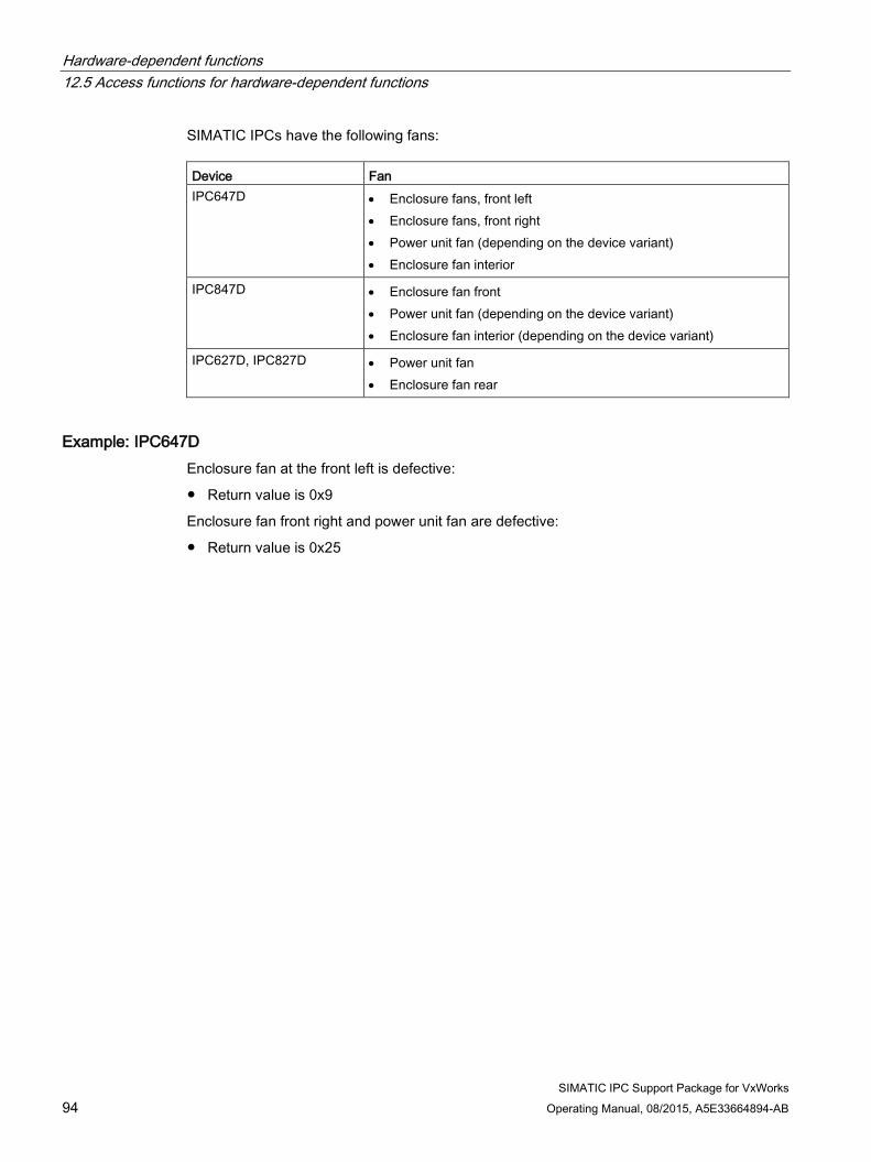
Hardware-dependent functions 12.5 Access functions for hardware-dependent functions
SIMATIC IPC Support Package for VxWorks 94 Operating Manual, 08/2015, A5E33664894-AB
SIMATIC IPCs have the following fans: Device Fan IPC647D • Enclosure fans, front left
• Enclosure fans, front right • Power unit fan (depending on the device variant) • Enclosure fan interior
IPC847D • Enclosure fan front • Power unit fan (depending on the device variant) • Enclosure fan interior (depending on the device variant)
IPC627D, IPC827D • Power unit fan • Enclosure fan rear
Example: IPC647D Enclosure fan at the front left is defective:
● Return value is 0x9
Enclosure fan front right and power unit fan are defective:
● Return value is 0x25

Hardware-dependent functions 12.5 Access functions for hardware-dependent functions
SIMATIC IPC Support Package for VxWorks Operating Manual, 08/2015, A5E33664894-AB 95
12.5.4 ReadBatteryStatus The "ReadBatteryStatus()" function reads the CMOS battery status from a register. The user can use this function, for example, to regularly read the CMOS battery status from a task and prevent a battery failure in advance.
Include <cpuex.h>
Syntax int ReadBatteryStatus (void);
Return value Value Meaning 0 (OK) CMOS battery is OK 1 CMOS battery is empty 2 CMOS battery is low (remaining capacity is enough for one month or less) 4 A redundant power supply unit has failed -1 Call is not supported for this CPU -2 Cannot read the battery status
12.5.5 Operating hours counter The "Operating hours counter" function offers the option of activating a specific task as the operating hours counter of the system. This enables you, for example, to specify maintenance activities on the SIMATIC IPC and determine the elapsed time in minutes since commissioning of the SIMATIC IPC. The operating hours counter is updated cyclically depending on the specified update interval. For system startup intervals that are shorter than the update interval, you can trigger the update of the operating hours counter by calling the "UpdateOpHoursCounter()" function.
A threshold can be set for the operating hours counter with the "SetOpHoursCounter()" function. The threshold setting is saved in the "ophours.vxw" file and retained even after a restart. The "/IPC_HW" semaphore is set when the threshold is reached. Applications can query this semaphore on both the kernel level and the user level.

Hardware-dependent functions 12.5 Access functions for hardware-dependent functions
SIMATIC IPC Support Package for VxWorks 96 Operating Manual, 08/2015, A5E33664894-AB
12.5.5.1 SetOpHoursCounter The "SetOpHoursCounter()" function sets the threshold of the operating hours counter in the "ophours.vxs" file. When the threshold is exceeded, the "/IPC_HW" semaphore is set.
Include <cpuex.h>
Syntax int SetOpHoursCounter
(
unsigned int limitHoursCounter
);
Parameters Parameter Meaning limitHoursCounter Threshold in minutes; when this value is exceeded, the monitoring task sets the
"/IPC_HW" semaphore.
Return value Value Meaning 0 (OK) Function successfully executed. -1 The operating hours counter has not yet been initialized. -3 Cannot open the "ophours.vxw" file. -4 Cannot write to the "ophours.vxw" file. -6 The length of the "ophours.vxw" file is invalid.

Hardware-dependent functions 12.5 Access functions for hardware-dependent functions
SIMATIC IPC Support Package for VxWorks Operating Manual, 08/2015, A5E33664894-AB 97
12.5.5.2 GetOpHoursCounter The "GetOpHoursCounter()" function reads the threshold and the current status of the operating hours counter from the "ophours.vxw" file.
Include <cpuex.h>
Syntax int GetOpHoursCounter
(
unsigned int *hoursCounter,
unsigned int *limitHoursCounter
);
Parameters Parameter Meaning hoursCounter Pointer to the current status of the operating hours counter in minutes. limitHoursCounter Pointer to the threshold in minutes; when this value is exceeded, the monitoring
task sets the "/IPC_HW" semaphore.
Note
When a pointer has the value NULL, the corresponding parameter is not evaluated.
Return value Value Meaning 0 (OK) Function successfully executed. -1 The operating hours counter has not yet been initialized. -3 Cannot open the "ophours.vxw" file. -6 The length of the "ophours.vxw" file is invalid.

Hardware-dependent functions 12.5 Access functions for hardware-dependent functions
SIMATIC IPC Support Package for VxWorks 98 Operating Manual, 08/2015, A5E33664894-AB
12.5.5.3 UpdateOpHoursCounter The "UpdateOpHoursCounter()" function manually triggers the update of the operating hours counter value in the "ophours.vxw" file, i.e. outside the configured automatic update cycle. When the threshold is exceeded, the monitoring task sets the semaphore.
Include <cpuex.h>
Syntax int UpdateOpHoursCounter (void);
Return value Value Meaning 0 (OK) Function successfully executed. -1 The operating hours counter has not yet been initialized. -3 Cannot open the "ophours.vxw" file. -4 Cannot write to the "ophours.vxw" file. -6 The length of the "ophours.vxw" file is invalid.
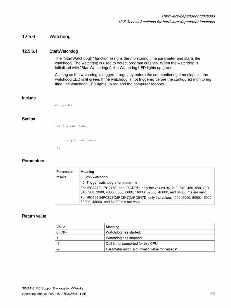
Hardware-dependent functions 12.5 Access functions for hardware-dependent functions
SIMATIC IPC Support Package for VxWorks Operating Manual, 08/2015, A5E33664894-AB 99
12.5.6 Watchdog
12.5.6.1 StartWatchdog The "StartWatchdog()" function assigns the monitoring time parameter and starts the watchdog. The watchdog is used to detect program crashes. When the watchdog is initialized with "StartWatchdog()", the Watchdog LED lights up green.
As long as the watchdog is triggered regularly before the set monitoring time elapses, the watchdog LED is lit green. If the watchdog is not triggered before the configured monitoring time, the watchdog LED lights up red and the computer reboots.
Include <cpuex.h>
Syntax int StartWatchdog
(
unsigned int msecs
);
Parameters Parameter Meaning msecs 0: Stop watchdog
>0: Trigger watchdog after msecs ms For IPC227E, IPC277E, and IPC427D, only the values 94, 210, 340, 460, 590, 710, 840, 960, 2000, 4000, 6000, 8000, 16000, 32000, 48000, and 64000 ms are valid. For IPC627D/IPC827D/IPC647D/IPC847D, only the values 4000, 6000, 8000, 16000, 32000, 48000, and 64000 ms are valid.
Return value Value Meaning 0 (OK) Watchdog has started. 1 Watchdog has stopped. -1 Call is not supported for this CPU. -2 Parameter error (e.g. invalid value for "msecs").

Hardware-dependent functions 12.5 Access functions for hardware-dependent functions
SIMATIC IPC Support Package for VxWorks 100 Operating Manual, 08/2015, A5E33664894-AB
12.5.6.2 TriggerWatchdog The "TriggerWatchdog()" function triggers the watchdog.
Include <cpuex.h>
Syntax int TriggerWatchdog (void);
Return value Value Meaning 0 (OK) Watchdog has been triggered. 1 Watchdog cannot be triggered because the watchdog has not started. -1 Call is not supported for this CPU.
12.5.7 LED You can set user LEDs with specific calls from within the application for all SIMATIC IPCs.
● IPC227E, IPC427D User LEDs "L1" (two colors, green and orange), "L2", and "L3" (two colors, red and orange) can be set.
● IPC627D/IPC827D User LEDs "L1", "L2", and "L3" (three colors, green, red, and orange) can be set.
● IPC647D/IPC847D User LEDs "HDD0 ALARM" and "HDD1 ALARM" can be set to red.
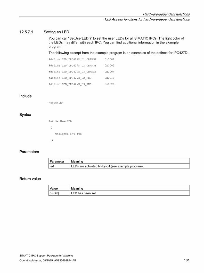
Hardware-dependent functions 12.5 Access functions for hardware-dependent functions
SIMATIC IPC Support Package for VxWorks Operating Manual, 08/2015, A5E33664894-AB 101
12.5.7.1 Setting an LED You can call "SetUserLED()" to set the user LEDs for all SIMATIC IPCs. The light color of the LEDs may differ with each IPC. You can find additional information in the example program.
The following excerpt from the example program is an examples of the defines for IPC427D:
#define LED_IPC427D_L1_ORANGE 0x0001
#define LED_IPC427D_L2_ORANGE 0x0002
#define LED_IPC427D_L3_ORANGE 0x0004
#define LED_IPC427D_L2_RED 0x0010
#define LED_IPC427D_L3_RED 0x0020
Include <cpuex.h>
Syntax int SetUserLED
(
unsigned int led
);
Parameters Parameter Meaning led LEDs are activated bit-by-bit (see example program).
Return value Value Meaning 0 (OK) LED has been set.

Hardware-dependent functions 12.5 Access functions for hardware-dependent functions
SIMATIC IPC Support Package for VxWorks 102 Operating Manual, 08/2015, A5E33664894-AB
12.5.7.2 Resetting LEDs You can call "ResetUserLED()" to reset the user LEDs for all SIMATIC IPCs.
Include <cpuex.h>
Syntax int ResetUserLED
(
unsigned int led
);
Parameters Parameter Meaning LED LEDs are activated bit-by-bit (see example program).
Return value Value Meaning 0 (OK) LED has been reset.

Hardware-dependent functions 12.5 Access functions for hardware-dependent functions
SIMATIC IPC Support Package for VxWorks Operating Manual, 08/2015, A5E33664894-AB 103
12.5.8 GetSMARTStatus
Description The "GetSMARTStatus()" function reads out the SMART status information of a particular drive. The drive can be a hard disk (only SATA), a Solid State Drive or a SIMATIC CompactFlash card.
Note
The "GetSMARTStatus ()" function then supplies the valid values only if the hardware to be tested supports the SMART functionality.
Include <cpuex.h>
Syntax int GetSMARTStatus
(
const char *volumeName
);
Parameter Parameter Meaning volumeName Drive designation, for example, "/ata0"
Return value Value Meaning 0 (OK) Hard disk / flash card is OK 1 A threshold specified by the manufacturer has been exceeded.
Hard disk / flash card should no longer be used. -1 Hard disk / flash card does not support any SMART functions -2 The mass storage driver is not started -3 Invalid drive name or null pointer for parameter "volume name" -4 An error has occurred in the mass storage driver.

Hardware-dependent functions 12.5 Access functions for hardware-dependent functions
SIMATIC IPC Support Package for VxWorks 104 Operating Manual, 08/2015, A5E33664894-AB
12.5.9 GetCMOSDateTime
Description The "GetCMOSDateTime()" function reads out the date and time of the RTC (Real Time Clock) and stores the result in the "structure tm".
The "structure tm" is defined as follows in the header file "time.h":
struct tm
{
int tm_sec; /* seconds after the minute - [0, 59] */
int tm_min; /* minutes after the hour - [0, 59] */
int tm_hour; /* hours after midnight - [0, 23] */
int tm_mday; /* day of the month - [1, 31] */
int tm_mon; /* months since January - [0, 11] */
int tm_year; /* years since 1900 */
int tm_wday; /* days since Sunday - [0, 6] */
int tm_yday; /* days since January 1 - [0, 365] */
int tm_isdst; /* Daylight Saving Time flag */
};
The tm_isdst element is of no significance.
Include <cpuex.h>
Syntax int GetCMOSDateTime
(
struct tm *pTime
);
Parameter Parameter Meaning pTime Pointer to structure tm
Return value Value Meaning 0 (OK) Function successful

Hardware-dependent functions 12.5 Access functions for hardware-dependent functions
SIMATIC IPC Support Package for VxWorks Operating Manual, 08/2015, A5E33664894-AB 105
12.5.10 SetCMOSDateTime
Description The "SetCMOSDateTime()" function sets the date and time of the real-time clock (RTC) based on the "structure tm". It is not checked whether this is a meaningful date or time information.
The "structure tm" is defined as follows in the header file "time.h":
struct tm
{
int tm_sec; /* seconds after the minute - [0, 59] */
int tm_min; /* minutes after the hour - [0, 59] */
int tm_hour; /* hours after midnight - [0, 23] */
int tm_mday; /* day of the month - [1, 31] */
int tm_mon; /* months since January - [0, 11] */
int tm_year; /* years since 1900 */
int tm_wday; /* days since Sunday - [0, 6] */
int tm_yday; /* days since January 1 - [0, 365] */
int tm_isdst; /* Daylight Saving Time flag */
};
The tm_wday, tm_yday, and tm_isdst elements are of no significance and are not evaluated.
Include <cpuex.h>
Syntax int SetCMOSDateTime
(
struct tm *pTime
);
Parameter Parameter Meaning pTime Pointer to structure tm
Return value Value Meaning 0 (OK) Function successful

Hardware-dependent functions 12.5 Access functions for hardware-dependent functions
SIMATIC IPC Support Package for VxWorks 106 Operating Manual, 08/2015, A5E33664894-AB

SIMATIC IPC Support Package for VxWorks Operating Manual, 08/2015, A5E33664894-AB 107
DiagMonitor Agent for VxWorks 13 13.1 Overview
The optional SIMATIC IPC DiagMonitor software (ordered separately) enables remote monitoring of SIMATIC IPCs in Windows. When used together with VxWorks, the SIMATIC IPC DiagMonitor software version 4.4.x or higher is required.
Even in their basic configuration level, SIMATIC Industrial PCs support the use of monitoring functions. When used in combination with the DiagMonitor software, the following display, monitoring, and control functions are available:
● Temperature monitoring (over/undertemperature, cable break of temperature sensor)
● Fan monitoring (underspeed, fan failure, tachometer cable break)
● Monitoring of the battery voltage
● Monitoring of the hard disks with S.M.A.R.T. functionality
● Watchdog (hardware or software reset of the computer)
● Operating hours counter (information on total runtime)
With the SIMATIC IPC DiagMonitor software, you can make use of these functions for monitoring. SIMATIC IPC DiagMonitor consists of two parts:
● DiagMonitor Management Explorer:
Runs in Windows
● DiagMonitor Agent:
Supplies data to the Windows system via SNMP in VxWorks
Der DiagMonitor Management Explorer lists the monitored device components and their status in an overview.
The VxWorks Target Name is used to identify the station. This is set in the "boot line" with parameter "tn" (e.g., "tn=IPC427D) and must be unique in the network, see section Configuring an Ethernet interface (Page 28).
The hard disk view displays status information for all connected data storage media (HDD, SSD, CFAST, and USB). USB data storage media that are inserted or removed during runtime are detected and then added to or removed from the list of the drives in the hard disk view.
RAID configurations are not supported by DiagMonitor Agent for VxWorks.
To support the S.M.A.R.T. function for error detection of the hard disks, the AHCI SATA driver (INCLUDE_DRV_STORAGE_AHCI) VxWorks V6.9.4.3 or higher is needed. The Intel AHCI SATA driver is not compatible with the SIMATIC IPCs.
DiagMonitor Agent enables a station to monitor itself via a watchdog.
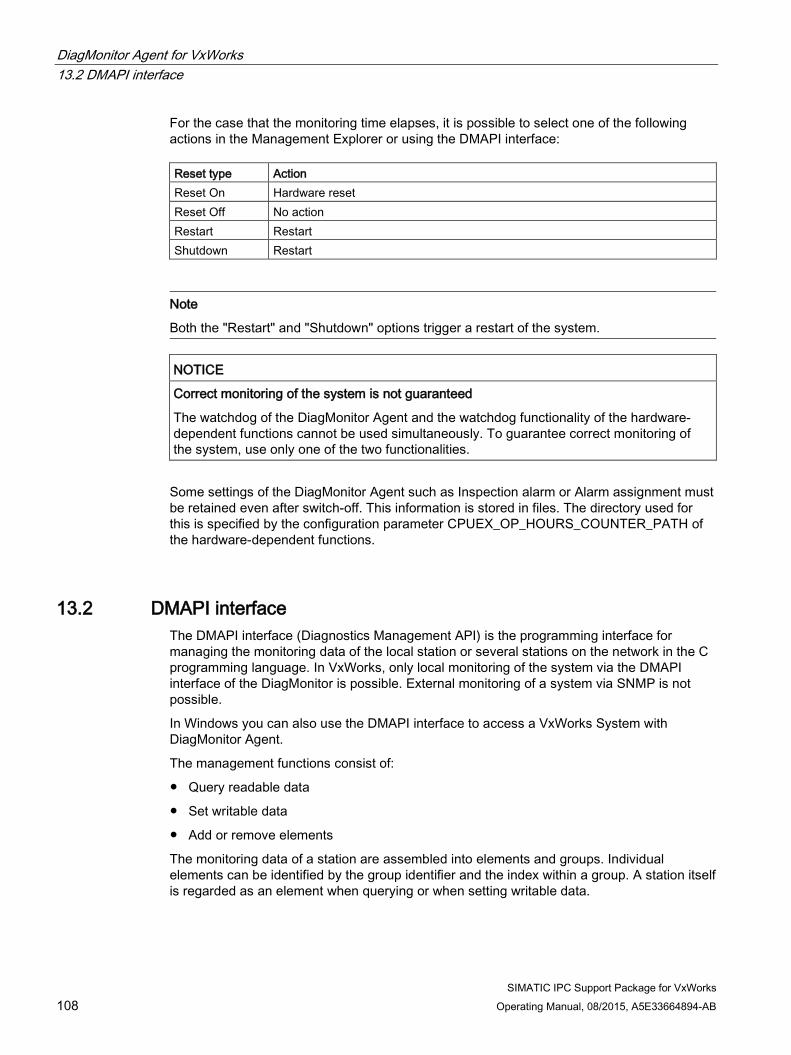
DiagMonitor Agent for VxWorks 13.2 DMAPI interface
SIMATIC IPC Support Package for VxWorks 108 Operating Manual, 08/2015, A5E33664894-AB
For the case that the monitoring time elapses, it is possible to select one of the following actions in the Management Explorer or using the DMAPI interface: Reset type Action Reset On Hardware reset Reset Off No action Restart Restart Shutdown Restart
Note
Both the "Restart" and "Shutdown" options trigger a restart of the system.
NOTICE
Correct monitoring of the system is not guaranteed
The watchdog of the DiagMonitor Agent and the watchdog functionality of the hardware-dependent functions cannot be used simultaneously. To guarantee correct monitoring of the system, use only one of the two functionalities.
Some settings of the DiagMonitor Agent such as Inspection alarm or Alarm assignment must be retained even after switch-off. This information is stored in files. The directory used for this is specified by the configuration parameter CPUEX_OP_HOURS_COUNTER_PATH of the hardware-dependent functions.
13.2 DMAPI interface The DMAPI interface (Diagnostics Management API) is the programming interface for managing the monitoring data of the local station or several stations on the network in the C programming language. In VxWorks, only local monitoring of the system via the DMAPI interface of the DiagMonitor is possible. External monitoring of a system via SNMP is not possible.
In Windows you can also use the DMAPI interface to access a VxWorks System with DiagMonitor Agent.
The management functions consist of:
● Query readable data
● Set writable data
● Add or remove elements
The monitoring data of a station are assembled into elements and groups. Individual elements can be identified by the group identifier and the index within a group. A station itself is regarded as an element when querying or when setting writable data.

DiagMonitor Agent for VxWorks 13.3 Operating hours counter of the DiagMonitor Agent
SIMATIC IPC Support Package for VxWorks Operating Manual, 08/2015, A5E33664894-AB 109
The following files are required for program development: File name Description DMAPI.h Header file of the DMAPI interface DMMCLConstants.h General constants DMMCLErrors.h Error constants DMMCLStatus.h Status of the monitoring objects DMMCLIdentifier.h Constants for identifying the monitoring objects
(group identifier, type identifier) DMMCLHWDStructs.h Structures of the monitoring objects DMColors.h Constants for the LED colors DMAPITypeDefs.h Type definitions for function pointers
The supplied example programs describe the application of the DMAPI interface.
Note
The DMInitSNMP, DMAddStation, and DMDeleteStation calls cannot be used in VxWorks.
13.3 Operating hours counter of the DiagMonitor Agent The operating hours counter of the hardware-dependent functions is identical to the operating hours counter of the DiagMonitor Agent and is stored retentively in the SIMATIC IPC.
13.4 Creating a VxWorks image DiagMonitor Agent uses the SNMP network protocol to provide station information. The SNMP support by VxWorks, however, is not in the form of a precompiled library; it must be generated from the source code. A "VxWorks Source Build (VSB) Project" is used for this. A VxWorks image project can then be created based on this project.
Creating a VxWorks Source Build project 1. Open the Wind River Workbench. You can find it in the Windows Start menu under
"Start > All Programs > Wind River > Workbench".
2. Select a workspace. Select "File > New > Project".
3. In the following dialog window, open the "VxWorks 6.x" folder in the list box and then select the "VxWorks Source Build (Kernel Library) Project" option.

DiagMonitor Agent for VxWorks 13.4 Creating a VxWorks image
SIMATIC IPC Support Package for VxWorks 110 Operating Manual, 08/2015, A5E33664894-AB
4. In the next dialog window, enter a "Project name" (e.g., "VSB_ipc_snmp") and select the "Create project in workspace" option.
5. Click "Next".
6. In the next window, click the "A CPU type:" option and select the "NEHALEM" item from the list.
7. Click "Finish".
A project is created.

DiagMonitor Agent for VxWorks 13.4 Creating a VxWorks image
SIMATIC IPC Support Package for VxWorks Operating Manual, 08/2015, A5E33664894-AB 111
Integrating components 1. Select the project view.
2. Double-click "Source Build Configuration" in the tree.
The area for the "Source Build Configuration" opens. The various components are displayed in this area.

DiagMonitor Agent for VxWorks 13.4 Creating a VxWorks image
SIMATIC IPC Support Package for VxWorks 112 Operating Manual, 08/2015, A5E33664894-AB
3. Open the Find dialog (CTRL + F) and enter "snmp" as the search term. Check whether the "COMPONENT_SNMP" and "COMPONENT_USR_SNMP" components are integrated (Y on green background).

DiagMonitor Agent for VxWorks 13.4 Creating a VxWorks image
SIMATIC IPC Support Package for VxWorks Operating Manual, 08/2015, A5E33664894-AB 113
4. If you need multicore support in your VxWorks image, search for the "SMP" component and integrate it with a double-click.
Creating a Source Build project 1. Select "Project > Build Project".
The creation of the project is started.

DiagMonitor Agent for VxWorks 13.4 Creating a VxWorks image
SIMATIC IPC Support Package for VxWorks 114 Operating Manual, 08/2015, A5E33664894-AB
Creating a VxWorks image project 1. Create a new VxWorks image project; see section Generating a VxWorks image
(Page 15).
2. Select the following entries in the "Project Setup“ dialog, see step 8, section Selecting BSPs for SIMATIC IPCs (Page 15):
– Based on: a source build project
– Project: Your Source Build project with SNMP support (here: VSB_ipc_snmp)
– BSP: BSP that is suitable for your IPC (here: itl_sandybridge). You can find information on this in the table at the beginning of section: Selecting BSPs for SIMATIC IPCs (Page 15).
3. Also integrate the INCLUDE_DIAGMONITOR_AGENT component and ensure that the
"target name" (tn) parameter is set in the "boot line“.

DiagMonitor Agent for VxWorks 13.5 Messages
SIMATIC IPC Support Package for VxWorks Operating Manual, 08/2015, A5E33664894-AB 115
13.5 Messages
Startup message of the driver VxWorks SIMATIC IPC Diagmonitor Agent V1.0.x
(C) Copyright 2015, Siemens AG. All rights reserved.
Error messages of the driver In problem situations, DiagMonitor Agent outputs suitable warnings and error messages on the system console. These outputs have the following format:
*** diagmonitor: <text>
Note
If an error occurs, contact Technical Support, see section Service and support (Page 129).
13.6 Configuration The priority of the tasks generated by DiagMonitor Agent (default: 99) can be configured. Values from 10 to 254 are permitted. This parameter is displayed in the configuration of the "INCLUDE_DIAGMONITOR_AGENT“ component when a VxWorks image is generated and can be edited.
The base priority is configured with the "DIAG_PRIORITY" parameter.

DiagMonitor Agent for VxWorks 13.6 Configuration
SIMATIC IPC Support Package for VxWorks 116 Operating Manual, 08/2015, A5E33664894-AB
The names of all tasks generated by DiagMonitor Agent begin with "diag_“ (e.g., diag_t1, diag_driver).
The table below shows the tasks created by DiagMonitor Agent and the priorities assigned to these tasks. Task name Description Priority diag_driver Task for processing Base priority diag_Timer Base priority diag_tLlMnr Task for processing LLMNR requests Base priority diag_t0 Task for status query of the hardware watchdog 1 diag_t1 Base priority diag_t2 Base priority diag_t3 Base priority diag_t4 Base priority diag_t5 Base priority diag_t18 Base priority - 1

SIMATIC IPC Support Package for VxWorks Operating Manual, 08/2015, A5E33664894-AB 117
VxWorks V7 14
VxWorks V7 is the successor to VxWorks V6.9.
Wind River Workbench 4 is the development environment of VxWorks V7.
Wind River Workbench 3.3 is the development environment of VxWorks V6.9.
This section describes the settings and development steps that differ from those described for VxWorks V6.9.
Note Different versions of VxWorks
This following sections refer to the VxWorks version 7.
If a topic is not described for VxWorks V7, this means that the preceding information for VxWorks V6.9 on this topic remains valid.
The following then applies to the respective topic for VxWorks V7: • The path "<installDir>\WindRiver\vxworks-7" must be used for the abbreviation
"<WIND_BASE>". • The file paths for the different versions are as follows:
– VxWorks V6.9: "<WIND_BASE>\target\3rdparty\siemens\" – VxWorks V7: "<WIND_BASE>\pkgs\siemens\simatic_ipc_sp-w.x.y.z\"
14.1 Installation on the development computer
Procedure To install the SIMATIC IPC Support Package for VxWorks V7, follow these steps:
1. Insert the product CD into the drive of your development computer.
2. Start the file manager (e.g., Explorer).
3. Call the "setup.exe" program on the product CD in folder "IPC_Support_Package_for _VxWorks_7" and follow the instructions.
Result The installation is complete.

VxWorks V7 14.2 Generating an image
SIMATIC IPC Support Package for VxWorks 118 Operating Manual, 08/2015, A5E33664894-AB
Storage of the files in the file system After the installation, the files are stored in the following directory tree:
(<WIND_BASE>\pkgs\siemens) | \--- simatic_ipc_sp-w.x.y.z SIMATIC IPC Support Package layer | | +---cdf | *.cdf Component definition files for Siemens components | +---docs | *.pdf Documentation for Siemens components | +---examples | *.* Examples for Siemens components | +---h | *.h Header files for Siemens components | +---lib | lib*.a Library for Siemens components | \--- <additional directories and files>
Observe the Readme file with important information on the SIMATIC IPC Support Package for VxWorks.
The Readme file is located in the main directory of the CD and in the directory "<WIND_BASE>\pkgs\siemens\simatic_ipc_sp-w.x.y.z".
14.2 Generating an image
Creating a Source Build project 1. Open the Wind River Workbench.
You can find it in the Windows Start menu under "Start > All Programs > Wind River > Workbench".
2. Select a workspace in which you want to create your VxWorks image project.
3. Select "File > New > Wind River Workbench Project".
4. In the next dialog window, select the "Source Build" option.
5. Click "Next>".

VxWorks V7 14.2 Generating an image
SIMATIC IPC Support Package for VxWorks Operating Manual, 08/2015, A5E33664894-AB 119
6. In the next dialog window, enter a "Project name" (e.g., "VSB_manual") and select the "Create project in workspace" option.
7. Click "Next>".

VxWorks V7 14.2 Generating an image
SIMATIC IPC Support Package for VxWorks 120 Operating Manual, 08/2015, A5E33664894-AB
8. Select the BSP. Select the following settings from the corresponding lists:
– Based on: "a VxWorks 6.9 compatible board support package"
– BSP: the board support package "bsp6x_itl_x86“ in the latest version
– Options - Processor mode: "SMP support in Libraries".
9. Click "Finish".

VxWorks V7 14.2 Generating an image
SIMATIC IPC Support Package for VxWorks Operating Manual, 08/2015, A5E33664894-AB 121
Select components 1. Select the project view.
2. Double-click "Source Build Configuration" in the tree structure of your project.
The area for the "Source Build Configuration" opens. The various components are displayed in this area.

VxWorks V7 14.2 Generating an image
SIMATIC IPC Support Package for VxWorks 122 Operating Manual, 08/2015, A5E33664894-AB
3. In the "Source Build Configuration" view, open the "siemens“ folder and double-click the "SIMATIC_IPC" layer.
Note
The version of the component shown in the screenshot is an example. If you have installed more than one version of the SIMATIC IPC Support Package for VxWorks, all of them are displayed.
Creating a Source Build project 1. Select "Project > Build Project".
The project is created.

VxWorks V7 14.2 Generating an image
SIMATIC IPC Support Package for VxWorks Operating Manual, 08/2015, A5E33664894-AB 123
Creating a VxWorks image project 1. Select "File > New > Wind River Workbench Project".
2. In the next dialog window, select the "Kernel Image" option.
3. In the next dialog window, enter a "Project name" (e.g., "VIP_manual") and select the "Create project in workspace" option.
4. Click "Next>".

VxWorks V7 14.2 Generating an image
SIMATIC IPC Support Package for VxWorks 124 Operating Manual, 08/2015, A5E33664894-AB
5. Under "Project", select the Source Build project you have just created.
6. Click "Finish".

VxWorks V7 14.3 Bootloader for VxWorks
SIMATIC IPC Support Package for VxWorks Operating Manual, 08/2015, A5E33664894-AB 125
Configuring and creating a VxWorks image
Configure the image project, see section Generating a VxWorks image (Page 15).
Note
Some of the components of VxWorks V6.9 may no longer be present in VxWorks V7.
Enabling a connection for debugging You can enable a debug connection to Workbench.
Select the following components:
● VxWorks Stop Mode Debug Agent (INLCUDE_STOP_MODE_AGENT)
● Debug Agent Start (INCLUDE_DEBUG_AGENT_START)
14.3 Bootloader for VxWorks For VxWorks V7 with BSPs that are compatible with VxWorks 6.9, the system start with VxWorks Bootloader is not supported. Use GRUB instead.
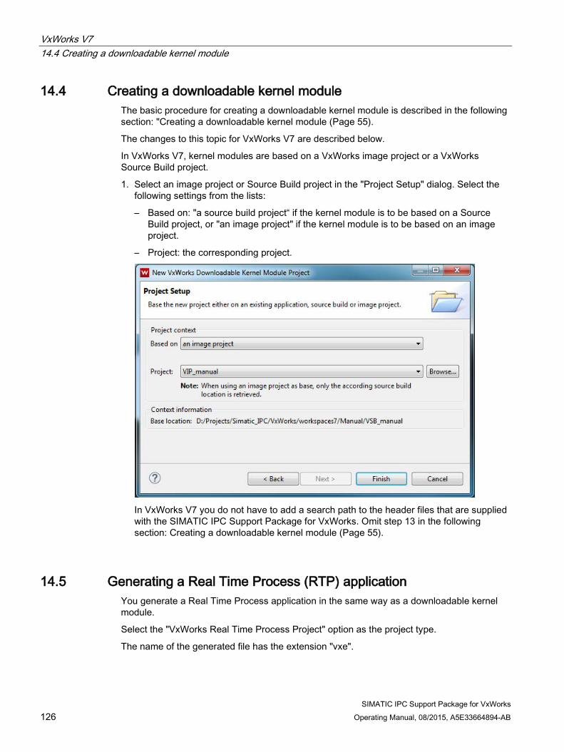
VxWorks V7 14.4 Creating a downloadable kernel module
SIMATIC IPC Support Package for VxWorks 126 Operating Manual, 08/2015, A5E33664894-AB
14.4 Creating a downloadable kernel module The basic procedure for creating a downloadable kernel module is described in the following section: "Creating a downloadable kernel module (Page 55).
The changes to this topic for VxWorks V7 are described below.
In VxWorks V7, kernel modules are based on a VxWorks image project or a VxWorks Source Build project.
1. Select an image project or Source Build project in the "Project Setup" dialog. Select the following settings from the lists:
– Based on: "a source build project“ if the kernel module is to be based on a Source Build project, or "an image project" if the kernel module is to be based on an image project.
– Project: the corresponding project.
In VxWorks V7 you do not have to add a search path to the header files that are supplied with the SIMATIC IPC Support Package for VxWorks. Omit step 13 in the following section: Creating a downloadable kernel module (Page 55).
14.5 Generating a Real Time Process (RTP) application You generate a Real Time Process application in the same way as a downloadable kernel module.
Select the "VxWorks Real Time Process Project" option as the project type.
The name of the generated file has the extension "vxe".

VxWorks V7 14.6 Using PROFINET calls in the Real Time Process (user mode)
SIMATIC IPC Support Package for VxWorks Operating Manual, 08/2015, A5E33664894-AB 127
14.6 Using PROFINET calls in the Real Time Process (user mode) You can use all PROFINET calls in a Real Time Process (RTP). Use the supplied "vxwpnio.h" header file for this. Integrate one of the supplied libraries, depending on the driver:
● CP 16xx driver:
"libcp16xx_rtp.a"
● PN driver:
"libpn_rtp.a" In RTP mode, almost all of the driver code is executed on the user level (privilege level 3).
Syscall group 51 is used for communication between user mode and kernel mode. You can find information regarding the configuration of this value in section "Configuring the PROFINET driver (Page 72)".

VxWorks V7 14.6 Using PROFINET calls in the Real Time Process (user mode)
SIMATIC IPC Support Package for VxWorks 128 Operating Manual, 08/2015, A5E33664894-AB

SIMATIC IPC Support Package for VxWorks Operating Manual, 08/2015, A5E33664894-AB 129
Service and support A
You can find additional information and support for the products described on the Internet at the following addresses:
● Technical support (http://www.siemens.de/automation/csi_en_WW)
● Support request form (http://www.siemens.com/automation/support-request)
● After-sales information system for SIMATIC PC / PG (http://www.siemens.com/asis)
● SIMATIC Documentation Collection (http://www.siemens.com/simatic-tech-doku-portal)
● Your local representative (http://www.automation.siemens.com/mcms/aspa-db/en/Pages/default.aspx)
● Training center (http://sitrain.automation.siemens.com/sitrainworld/?AppLang=en)
● Industry Mall (https://mall.industry.siemens.com)
When contacting your local representative or Technical Support, please have the following information at hand:
● Order number of the device (MLFB)
● BIOS version (industry PC) or image version (HMI device)
● Installed additional hardware
● Installed additional software
Tools & downloads Please check regularly if updates and hotfixes are available for download to your device. The downloads are available on the Internet under "After Sales Information System SIMATIC PC/PG" (see above).

Service and support
SIMATIC IPC Support Package for VxWorks 130 Operating Manual, 08/2015, A5E33664894-AB

SIMATIC IPC Support Package for VxWorks Operating Manual, 08/2015, A5E33664894-AB 131
Index
B Battery monitoring, 7 Baud rate, 29, 39 Bootloader, 43
C CMD Shell, 65 Configuration, 7, 68, 79, 82, 87 Configuration software, 12 Configuring, 29, 43, 70, 78, 86 CPU basic setting, 7 CPUEX_OP_HOURS_COUNTER_CYCLE, 88 CPUEX_OP_HOURS_COUNTER_PATH, 88 CPUEX_OP_HOURS_COUNTER_PRIORITY, 88 CPUEX_RAMDISK_MODE, 88 CPUEX_RAMDISK_SIZE, 88 CPUEX_SYSCALLGROUP, 88
D Debugging, 29, 62 DiagMonitor, 107 DiagMonitor Agent, 107 DKM, 67, 69, 75, 85 DMAPI, 108 Downloadable Kernel Module, 55, 59, 67 DP_CP5622_SYSCALLGROUP, 79 DP-Base interface, 7, 75
E Ethernet interface, 28, 67, 74 Example program, 101
F Fan monitoring, 7
G GetCMOSDateTime(), 89 GetCPUTypeDMI(), 89, 90 GetOpHoursCounter(), 89, 97 GetSMARTStatus(), 89 GRUB, 46, 48, 50
H Hardware-dependent function, 7, 11 Hardware-dependent functions, 85
I Installation, 13 IO-Base interface, 7, 69
K Kernel mode, 67, 70, 73, 74, 75, 78, 79, 86, 88 Kernel Modul, 55 Kernel module, 57, 59, 77, 85
L LED
Resetting, 102 Setting, 101
M Message, 27, 71, 78, 86
O Operating hours counter, 7, 87, 89, 95, 96, 97

Index
SIMATIC IPC Support Package for VxWorks 132 Operating Manual, 08/2015, A5E33664894-AB
P PNIO_CP16XX_PRIORITY, 72 PNIO_CP16XX_SYSCALLGROUP, 73, 74 PROFIBUS, 7, 11, 75, 76, 82
Configuring, 79, 80, 82 PROFINET, 7, 11, 18, 67, 71, 73, 74
Configuring the PN driver, 69 CP 16xx driver, 67 Example, 22 IRT, 67 PN driver, 67 PROFIenergy, 69 RT, 67
R RAMDISK, 85, 87, 88 ReadBatteryStatus(), 89, 95 ReadFanStatus(), 89, 93 ReadTemperature(), 89, 91 Real Time Process, 59, 61, 67, 70, 75, 78, 86 Real Time Process Project, 29 ResetUserLED(), 89, 102 Retentive memory, 7, 85 RTP, 29, 59, 61, 67, 70, 78
S SetCMOSDateTime(), 89 SetOpHoursCounter(), 89, 96 SetUserLED(), 89, 101 SNMP, 108, 109 Source Build Project, 114, 126 StartWatchdog(), 89, 99 Syscall group, 70, 72, 74, 78, 79, 86
T TCP/IP Debug, 29 Temperature monitoring, 7 TriggerWatchdog(), 89, 100
U UpdateOpHoursCounter(), 89, 95, 98 User LED, 7, 85, (LED)User mode, 67, 70, 73, 74, 75, 78, 79, 86, 88
V VxWorks image, 15, 17, 27, 32, 43, 87 VxWorks Source Build Project, 114, 126 VxWorks V6.9, 12, 117 VxWorks V7, 12, 117
W Watchdog, 7, 72, 99, 100 Workbench, 11, 15, 16, 17, 29, 32, 55, 57 Workspace, 15, 32