Embed Size (px)
Citation preview

SIMATIC Ident
Configuration Manual · 02/2013
SIMATIC RF620R/RF630R
RFID SYSTEMS

� �SIMATIC RF620R/RF630R
___________________
___________________
___________________
___________________
___________________
___________________
___________________
___________________
___________________
SIMATIC Ident
RFID systemsSIMATIC RF620R/RF630R
Configuration Manual
02/2013 J31069-D0196-U001-A5-7618
Introduction 1
Description 2
Commissioning 3
Parameterizing 4
Error messages and troubleshooting
5
Industrial UHF algorithms 6
Appendix A
Firmware update B
Service & Support C
Siemens AG Industry Sector Postfach 48 48 90026 NÜRNBERG GERMANY
Order number: J31069-D0196-U001 Ⓟ 02/2013 Technical data subject to change
Copyright © Siemens AG 2008 - 2013.All rights reserved
Legal information Warning notice system
This manual contains notices you have to observe in order to ensure your personal safety, as well as to prevent damage to property. The notices referring to your personal safety are highlighted in the manual by a safety alert symbol, notices referring only to property damage have no safety alert symbol. These notices shown below are graded according to the degree of danger.
DANGER indicates that death or severe personal injury will result if proper precautions are not taken.
WARNING indicates that death or severe personal injury may result if proper precautions are not taken.
CAUTION indicates that minor personal injury can result if proper precautions are not taken.
NOTICE indicates that property damage can result if proper precautions are not taken.
If more than one degree of danger is present, the warning notice representing the highest degree of danger will be used. A notice warning of injury to persons with a safety alert symbol may also include a warning relating to property damage.
Qualified Personnel The product/system described in this documentation may be operated only by personnel qualified for the specific task in accordance with the relevant documentation, in particular its warning notices and safety instructions. Qualified personnel are those who, based on their training and experience, are capable of identifying risks and avoiding potential hazards when working with these products/systems.
Proper use of Siemens products Note the following:
WARNING Siemens products may only be used for the applications described in the catalog and in the relevant technical documentation. If products and components from other manufacturers are used, these must be recommended or approved by Siemens. Proper transport, storage, installation, assembly, commissioning, operation and maintenance are required to ensure that the products operate safely and without any problems. The permissible ambient conditions must be complied with. The information in the relevant documentation must be observed.
Trademarks All names identified by ® are registered trademarks of Siemens AG. The remaining trademarks in this publication may be trademarks whose use by third parties for their own purposes could violate the rights of the owner.
Disclaimer of Liability We have reviewed the contents of this publication to ensure consistency with the hardware and software described. Since variance cannot be precluded entirely, we cannot guarantee full consistency. However, the information in this publication is reviewed regularly and any necessary corrections are included in subsequent editions.
SIMATIC RF620R/RF630R Configuration Manual, 02/2013, J31069-D0196-U001-A5-7618 3
Table of contents
1 Introduction................................................................................................................................................ 7
1.1 Validity of the documentation.........................................................................................................7
1.2 Preface...........................................................................................................................................7
1.3 Abbreviations and naming conventions .........................................................................................9
1.4 Guide through the parameterization manual .................................................................................9
2 Description............................................................................................................................................... 11
3 Commissioning ........................................................................................................................................ 13
3.1 Connecting the hardware.............................................................................................................13
3.2 Setting up the software ................................................................................................................15 3.2.1 1. Step: Install ASM/communication module in STEP 7..............................................................15 3.2.2 2. Step: Configuring hardware in STEP 7....................................................................................16 3.2.3 3. Step: Set properties of the ASM/communication module ........................................................18 3.2.4 4. Step: Insert blocks in the STEP 7 project ................................................................................19 3.2.5 5. Step: Download and test the program .....................................................................................20
4 Parameterizing ........................................................................................................................................ 23
4.1 Overview of commands ...............................................................................................................23
4.2 FB 45 parameter assignment.......................................................................................................25 4.2.1 Configuration scheme of FB 45 ...................................................................................................25 4.2.2 Parameter assignment in the parameter DB ...............................................................................25 4.2.3 INPUT parameters .......................................................................................................................27 4.2.4 Command and status word ..........................................................................................................31 4.2.5 Further displays ...........................................................................................................................33 4.2.6 RFID commands of FB 45 ...........................................................................................................34 4.2.7 Parameter assignment of the commands with FB 45..................................................................35 4.2.7.1 Overview of commands ...............................................................................................................35 4.2.7.2 WRITE..........................................................................................................................................35 4.2.7.3 READ ...........................................................................................................................................36 4.2.7.4 INIT ..............................................................................................................................................36 4.2.7.5 SLG STATUS...............................................................................................................................37 4.2.7.6 SET-ANT......................................................................................................................................39 4.2.7.7 MDS-STATUS..............................................................................................................................40 4.2.8 UDTs of FB 45 .............................................................................................................................41
4.3 FB 55 parameter assignment.......................................................................................................49 4.3.1 Configuration scheme of FB 55 ...................................................................................................49 4.3.2 Parameter assignment in the parameter DB ...............................................................................49 4.3.3 INPUT parameters .......................................................................................................................51 4.3.4 Command and status word ..........................................................................................................55 4.3.5 Further displays ...........................................................................................................................57 4.3.6 RFID commands of FB 55 ...........................................................................................................58 4.3.6.1 UDT 30 - the structure for the RFID command............................................................................58
Table of contents
SIMATIC RF620R/RF630R 4 Configuration Manual, 02/2013, J31069-D0196-U001-A5-7618
4.3.6.2 UID .............................................................................................................................................. 59 4.3.7 Parameter assignment of the commands with FB 55 ................................................................. 61 4.3.7.1 Overview of commands............................................................................................................... 61 4.3.7.2 WRITE......................................................................................................................................... 62 4.3.7.3 READ .......................................................................................................................................... 63 4.3.7.4 INIT.............................................................................................................................................. 63 4.3.7.5 SLG STATUS.............................................................................................................................. 64 4.3.7.6 SET-ANT..................................................................................................................................... 65 4.3.7.7 MDS-STATUS............................................................................................................................. 66 4.3.7.8 GET............................................................................................................................................. 67 4.3.7.9 Programming the "GET" command for transponders in the antenna field.................................. 69 4.3.7.10 Programming the "GET" command for transponders in the Black List ....................................... 70 4.3.8 UDTs of FB 55 ............................................................................................................................ 71
5 Error messages and troubleshooting ....................................................................................................... 83
5.1 Classification of error messages................................................................................................. 83
5.2 Error messages and flashing codes............................................................................................ 84
6 Industrial UHF algorithms ........................................................................................................................ 95
6.1 Memory configuration.................................................................................................................. 95
6.2 Special memory configuration of the RF600 transponders......................................................... 98
6.3 Use of industrial UHF algorithms ................................................................................................ 99 6.3.1 Overview of industrial UHF algorithms........................................................................................ 99 6.3.2 Status display of industrial UHF algorithms and RF600 blink codes ........................................ 101 6.3.3 Status display of industrial UHF algorithms using of SLG-STATUS......................................... 106 6.3.4 Tag list....................................................................................................................................... 114 6.3.5 Smoothing versus Inventory Threshold Filter (ITF) .................................................................. 115 6.3.6 Read/Write Boost algorithm ...................................................................................................... 119 6.3.7 Power Ramp algorithm.............................................................................................................. 119 6.3.8 Power Gap algorithm ................................................................................................................ 121 6.3.9 Filter mechanisms based on the RSSI or the EPC-IDs ............................................................ 122 6.3.9.1 RSSI Threshold......................................................................................................................... 122 6.3.9.2 Black List algorithm................................................................................................................... 124 6.3.9.3 EPC Data Filter ......................................................................................................................... 127 6.3.10 Intelligent Single-tag mode (ISTM) and sorting......................................................................... 134 6.3.11 Tag Hold algorithm.................................................................................................................... 136
6.4 Setting the Advanced User Parameters (AUP)......................................................................... 139
6.5 UDT for industrial UHF algorithms ............................................................................................ 148 6.5.1 UDT for Advanced User Parameters ........................................................................................ 148 6.5.2 UDT for EPC Data Filter............................................................................................................ 153
6.6 Writing the EPC-ID.................................................................................................................... 155
6.7 Special functions of the RF600 transponders ........................................................................... 157 6.7.1 Setting passwords and erasing them again .............................................................................. 157 6.7.2 Application of the LOCK function .............................................................................................. 159 6.7.3 (Perma) LOCK/(perma) UNLOCK and read or write accesses to transponders with
ACCESS password ................................................................................................................... 160 6.7.4 Codes for the LOCK function .................................................................................................... 161 6.7.5 Application of the KILL function ................................................................................................ 162
Table of contents
SIMATIC RF620R/RF630R Configuration Manual, 02/2013, J31069-D0196-U001-A5-7618 5
6.8 Command repetition and ScanningMode ..................................................................................163 6.8.1 Command repetition...................................................................................................................163 6.8.2 Enabling the ScanningMode......................................................................................................165 6.8.3 Operating conditions ..................................................................................................................166 6.8.4 Errors and special cases............................................................................................................167
6.9 Transmit / radiated power setting...............................................................................................168
A Appendix................................................................................................................................................ 169
A.1 Differences between SIMATIC command level and message frame level................................169
A.2 Programming the communications modules on PROFIBUS .....................................................171 A.2.1 Programming the communications modules on PROFIBUS DP-V1 .........................................171 A.2.2 Cyclic control word between master and communications module ...........................................174 A.2.3 Methods of operation with the communications module............................................................177 A.2.4 Command and acknowledgement telegrams ............................................................................181 A.2.5 PROFIBUS/PROFINET implementation....................................................................................190
A.3 Example of the writing the Advanced User Parameter "BlackListEntries".................................193
A.4 Example of the EPC-ID with SIMATIC RF600 industrial transponders .....................................194
A.5 Examples of (Perma) LOCK/(Perma) UNLOCK/KILL................................................................194 A.5.1 Example: Perma-LOCK command on EPC ID and temporary LOCK on USER memory
bank and ACCESS password of an RF640T Gen2 transponder...............................................194 A.5.2 Example: Permanent protection of a transponder against the KILL function ............................196
A.6 ACCESS/KILL password ...........................................................................................................197 A.6.1 Writing an ACCESS password on an RF630L in the delivery state ..........................................197 A.6.2 Write KILL password to an RF630L with temporary LOCK .......................................................198
A.7 Overview of the UDTs................................................................................................................200
B Firmware update.................................................................................................................................... 203
B.1 Requirements for the firmware update ......................................................................................203
B.2 Performing the firmware update.................................................................................................204
B.3 Firmware update with RF160C and ASM 456 ...........................................................................204
B.4 Firmware update with RF180C ..................................................................................................208
C Service & Support.................................................................................................................................. 213

Table of contents
SIMATIC RF620R/RF630R 6 Configuration Manual, 02/2013, J31069-D0196-U001-A5-7618
SIMATIC RF620R/RF630R Configuration Manual, 02/2013, J31069-D0196-U001-A5-7618 7
Introduction 11.1 Validity of the documentation
Note Scope of this documentation
This documentation is valid for the parameter assignment of the readers RF620R/RF630R as of firmware V2.5 with the function blocks FB 45 as of V1.8 and FB 55 as of V1.6. If you are assigning parameters for older firmware versions, please use the documentation edition 10/2009.
1.2 Preface
Purpose of this document This Configuration Manual contains all the information required to assign parameters to and commission the RF620R and RF630R readers of the SIMATIC RF600 system in conjunction with communications modules and FB 45 / FB 55.
This manual is intended for:
● Commissioning engineers
● Configuration engineers
● Service technicians
Documentation classification The commissioning of the communications modules is described in the operating instructions of the relevant interface modules/communications modules.
For programmers who want to create their own function block, the communications rules and frames can be found in the "Appendix (Page 171)".
These additional descriptions can be found in the "Service & Support Portal (http://support.automation.siemens.com)" on the Internet.
Introduction 1.2 Preface
SIMATIC RF620R/RF630R 8 Configuration Manual, 02/2013, J31069-D0196-U001-A5-7618
Option of connecting via communications modules
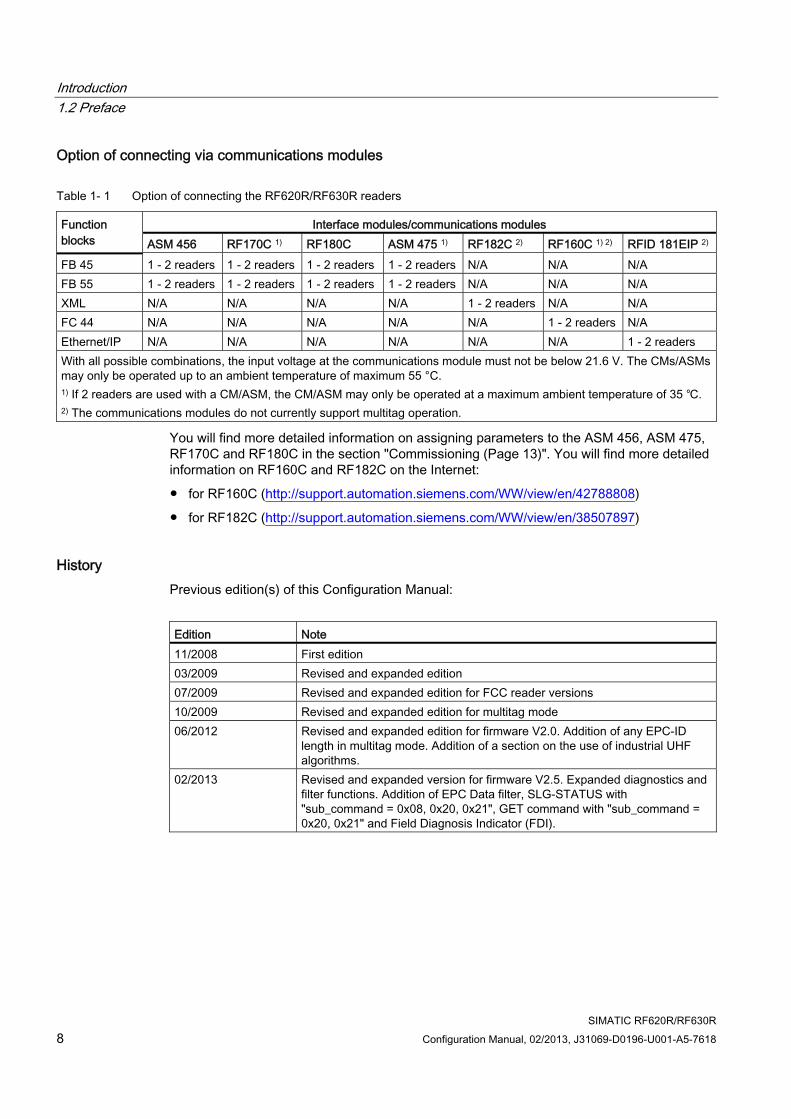
Table 1- 1 Option of connecting the RF620R/RF630R readers
Interface modules/communications modules Function blocks ASM 456 RF170C 1) RF180C ASM 475 1) RF182C 2) RF160C 1) 2) RFID 181EIP 2) FB 45 1 - 2 readers 1 - 2 readers 1 - 2 readers 1 - 2 readers N/A N/A N/A FB 55 1 - 2 readers 1 - 2 readers 1 - 2 readers 1 - 2 readers N/A N/A N/A XML N/A N/A N/A N/A 1 - 2 readers N/A N/A FC 44 N/A N/A N/A N/A N/A 1 - 2 readers N/A Ethernet/IP N/A N/A N/A N/A N/A N/A 1 - 2 readers With all possible combinations, the input voltage at the communications module must not be below 21.6 V. The CMs/ASMs may only be operated up to an ambient temperature of maximum 55 °C. 1) If 2 readers are used with a CM/ASM, the CM/ASM may only be operated at a maximum ambient temperature of 35 ℃. 2) The communications modules do not currently support multitag operation.
You will find more detailed information on assigning parameters to the ASM 456, ASM 475, RF170C and RF180C in the section "Commissioning (Page 13)". You will find more detailed information on RF160C and RF182C on the Internet:
● for RF160C (http://support.automation.siemens.com/WW/view/en/42788808)
● for RF182C (http://support.automation.siemens.com/WW/view/en/38507897)
History Previous edition(s) of this Configuration Manual:
Edition Note 11/2008 First edition 03/2009 Revised and expanded edition 07/2009 Revised and expanded edition for FCC reader versions 10/2009 Revised and expanded edition for multitag mode 06/2012 Revised and expanded edition for firmware V2.0. Addition of any EPC-ID
length in multitag mode. Addition of a section on the use of industrial UHF algorithms.
02/2013 Revised and expanded version for firmware V2.5. Expanded diagnostics and filter functions. Addition of EPC Data filter, SLG-STATUS with "sub_command = 0x08, 0x20, 0x21", GET command with "sub_command = 0x20, 0x21" and Field Diagnosis Indicator (FDI).
Introduction 1.3 Abbreviations and naming conventions
SIMATIC RF620R/RF630R Configuration Manual, 02/2013, J31069-D0196-U001-A5-7618 9
1.3 Abbreviations and naming conventions The following terms/abbreviations are used synonymously in this document:
Read/write device (SLG) Readers Mobile data storage units (MDS) Transponder, tag Interface module, ASM Communications module, CM
1.4 Guide through the parameterization manual Structure of contents Contents Table of Contents Organization of the documentation, including the index of pages and sections. Introduction Purpose, layout and description of the important topics. Description Basics of parameter assignment Commissioning Description of commissioning the hardware and software Parameter assignment Description of parameter assignment with the function blocks FB 45 and FB 55 Error messages and troubleshooting Overview of error messages and troubleshooting guide Industrial UHF algorithms Description of the applications and algorithms Appendix Frame expansions
Description of the firmware update for SIMATIC Service & Support Service and support, contact partners, training centers

Introduction 1.4 Guide through the parameterization manual
SIMATIC RF620R/RF630R 10 Configuration Manual, 02/2013, J31069-D0196-U001-A5-7618
SIMATIC RF620R/RF630R Configuration Manual, 02/2013, J31069-D0196-U001-A5-7618 11
Description 2
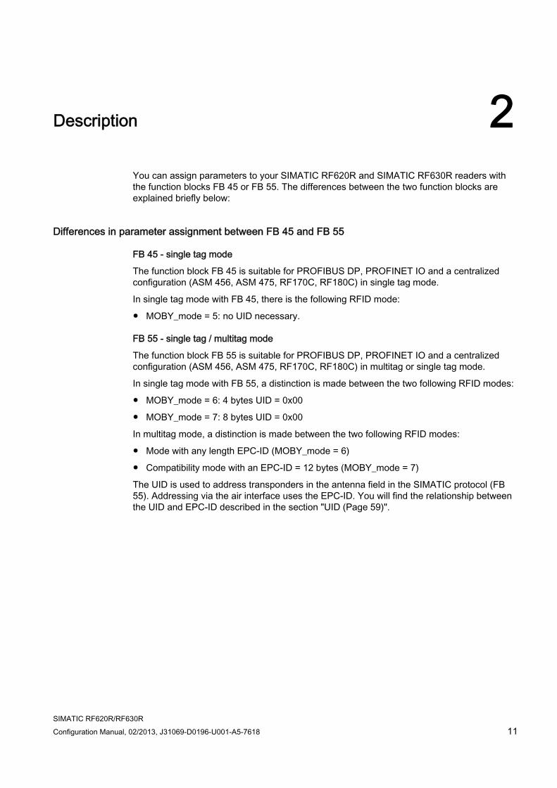
You can assign parameters to your SIMATIC RF620R and SIMATIC RF630R readers with the function blocks FB 45 or FB 55. The differences between the two function blocks are explained briefly below:
Differences in parameter assignment between FB 45 and FB 55
FB 45 - single tag mode
The function block FB 45 is suitable for PROFIBUS DP, PROFINET IO and a centralized configuration (ASM 456, ASM 475, RF170C, RF180C) in single tag mode.
In single tag mode with FB 45, there is the following RFID mode:
● MOBY_mode = 5: no UID necessary.
FB 55 - single tag / multitag mode
The function block FB 55 is suitable for PROFIBUS DP, PROFINET IO and a centralized configuration (ASM 456, ASM 475, RF170C, RF180C) in multitag or single tag mode.
In single tag mode with FB 55, a distinction is made between the two following RFID modes:
● MOBY_mode = 6: 4 bytes UID = 0x00
● MOBY_mode = 7: 8 bytes UID = 0x00
In multitag mode, a distinction is made between the two following RFID modes:
● Mode with any length EPC-ID (MOBY_mode = 6)
● Compatibility mode with an EPC-ID = 12 bytes (MOBY_mode = 7)
The UID is used to address transponders in the antenna field in the SIMATIC protocol (FB 55). Addressing via the air interface uses the EPC-ID. You will find the relationship between the UID and EPC-ID described in the section "UID (Page 59)".
Description
SIMATIC RF620R/RF630R 12 Configuration Manual, 02/2013, J31069-D0196-U001-A5-7618
Differences between single tag mode and multitag mode When using UHF readers, a distinction is made between operation in single tag mode and multitag mode. Which mode is more suitable for your requirements depends on the concrete situation.
The main feature of the single tag mode is that the reader only expects a single transponder in the antenna field as is often the case in a production environment. If, on the other hand, there are several transponders in the antenna field, the reader reports an error. The use of this mode is comparatively simple since all data access to the transponder is unspecific. This means that no transponder lists need to be managed and no addressing of the transponder using its ID is necessary.
The multitag mode can be used flexibly and allows the reader to manage several transponders in the antenna field as is often required in logistics. In this mode, however, for data access to transponders it is necessary to inform the reader precisely which transponder needs to be accessed based on an ID. The access is therefore multi-stage on the PLC. An initial step identifies which transponders are currently located in the antenna field. Using the application logic, one transponder is then selected that can be accessed specifically. The multitag mode can also be used when only one transponder is located in the antenna field.
SIMATIC RF620R/RF630R Configuration Manual, 02/2013, J31069-D0196-U001-A5-7618 13
Commissioning 3
Note Setting up software with the TIA Portal
You can also operate the RF600 readers in the TIA Portal with the communications modules. You will find more detailed information on operating the RF600 readers with the TIA Portal on the RFID system DVD "Software & Documentation".
3.1 Connecting the hardware
Requirements ● An interface/communications module is connected via PROFIBUS DP or via PROFINET
IO to the SIMATIC S7-300/400. The modules RF160C and RF182C are released for single tag mode and the modules ASM456, ASM475, RF170C and RF180C for multitag mode.
● The reader is connected via the RS-422 cable to the interface module being used.
● Internal or external antenna (RF620R) or one or two antennas (RF630R) are connected via standard antenna cables and the RTNC connector on the reader.
Commissioning 3.1 Connecting the hardware
SIMATIC RF620R/RF630R 14 Configuration Manual, 02/2013, J31069-D0196-U001-A5-7618
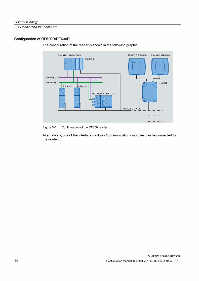
Configuration of RF620R/RF630R The configuration of the reader is shown in the following graphic:
Figure 3-1 Configuration of the RF600 reader
Alternatively, one of the interface modules /communications modules can be connected to the reader.
Commissioning 3.2 Setting up the software
SIMATIC RF620R/RF630R Configuration Manual, 02/2013, J31069-D0196-U001-A5-7618 15
3.2 Setting up the software
3.2.1 1. Step: Install ASM/communication module in STEP 7 To install the interface/communications modules in STEP 7, follow the steps below depending on the module you are using:
● PROFIBUS ASM
Link the GSD file to the device catalog using HW Config ("Options Install GSD file"...):
– Siem8114.GSD for ASM 456
– GSDML-V2.2-SIEMENS-RF180C-20100329.xml for RF180C
● RF170C and the ASM 475
Link the modules into the hardware catalog of STEP 7 using the "Hardware Support Package (HSP)". You will find the required HSP files on the current RFID system DVD "Software & Documentation" ("daten\S7_HSP").
Note The "S7-compatible" setting results in addressing errors!
To operate the ASM 456 using the relevant GSD file, the DP interface of the DP master must be set to "DP-V1".
Commissioning 3.2 Setting up the software
SIMATIC RF620R/RF630R 16 Configuration Manual, 02/2013, J31069-D0196-U001-A5-7618
3.2.2 2. Step: Configuring hardware in STEP 7 The configuration varies depending on which MOBY ASM/communications module is being used:
Example:
● RF170C: distributed configuration via PROFIBUS or PROFINET and ET 200pro
● RF180C: Distributed configuration via PROFINET
● ASM 456: Distributed setup with PROFIBUS
● ASM 475: Centralized configuration in S7-300
● ASM 475: Distributed configuration with PROFIBUS and ET 200M
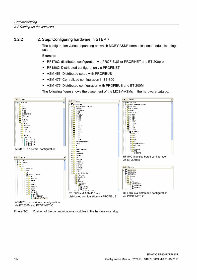
The following figure shows the placement of the MOBY-ASMs in the hardware catalog.
Figure 3-2 Position of the communications modules in the hardware catalog
Commissioning 3.2 Setting up the software
SIMATIC RF620R/RF630R Configuration Manual, 02/2013, J31069-D0196-U001-A5-7618 17
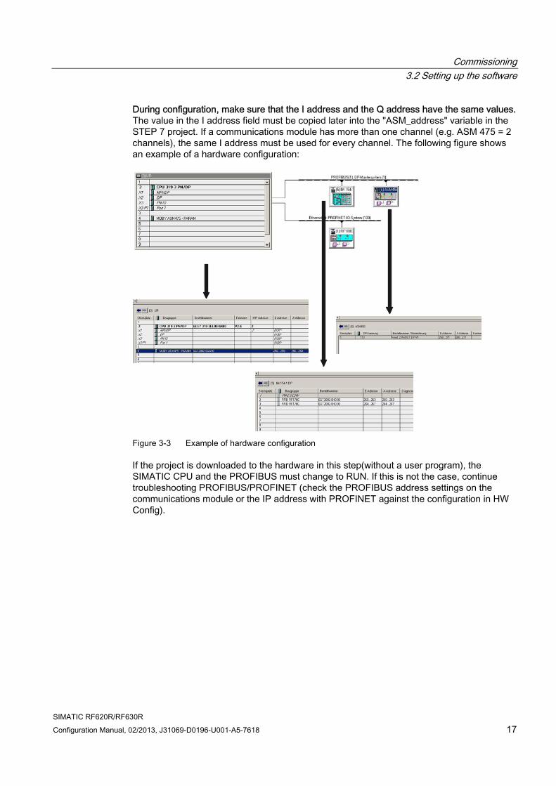
During configuration, make sure that the I address and the Q address have the same values. The value in the I address field must be copied later into the "ASM_address" variable in the STEP 7 project. If a communications module has more than one channel (e.g. ASM 475 = 2 channels), the same I address must be used for every channel. The following figure shows an example of a hardware configuration:
Figure 3-3 Example of hardware configuration
If the project is downloaded to the hardware in this step(without a user program), the SIMATIC CPU and the PROFIBUS must change to RUN. If this is not the case, continue troubleshooting PROFIBUS/PROFINET (check the PROFIBUS address settings on the communications module or the IP address with PROFINET against the configuration in HW Config).
Commissioning 3.2 Setting up the software
SIMATIC RF620R/RF630R 18 Configuration Manual, 02/2013, J31069-D0196-U001-A5-7618
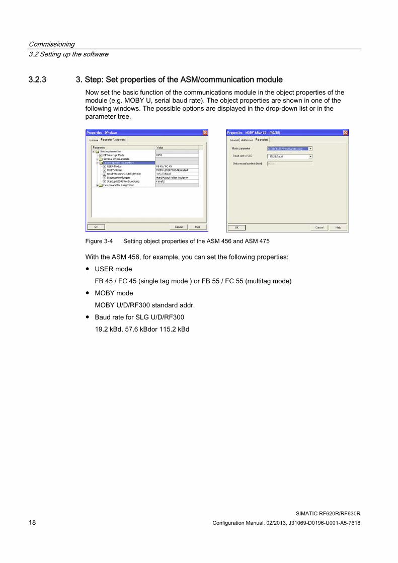
3.2.3 3. Step: Set properties of the ASM/communication module Now set the basic function of the communications module in the object properties of the module (e.g. MOBY U, serial baud rate). The object properties are shown in one of the following windows. The possible options are displayed in the drop-down list or in the parameter tree.
Figure 3-4 Setting object properties of the ASM 456 and ASM 475
With the ASM 456, for example, you can set the following properties:
● USER mode
FB 45 / FC 45 (single tag mode ) or FB 55 / FC 55 (multitag mode)
● MOBY mode
MOBY U/D/RF300 standard addr.
● Baud rate for SLG U/D/RF300
19.2 kBd, 57.6 kBdor 115.2 kBd
Commissioning 3.2 Setting up the software
SIMATIC RF620R/RF630R Configuration Manual, 02/2013, J31069-D0196-U001-A5-7618 19
3.2.4 4. Step: Insert blocks in the STEP 7 project This step is based on the sample program supplied with the system.
● Select the required block:
– Single tag mode: Function block FB 45 is suitable for PROFIBUS DP, PROFINET IO and a centralized configuration in single tag mode.
– Multitag mode: The function block FB 55 is suitable for PROFIBUS DP, PROFINET IO and a central configuration in multitag mode and single tag mode.
● Copy all blocks from the FB 45 or FB 55 sample program to the newly created STEP 7 project.
● Select the suitable UDT depending on the number of configured readers:
Single tag mode:
– In the data view of DB 45 (DB with UDT 10 structure), the parameters are declared for up to two readers (reader 1 = channel 1, reader 2 = channel 2).
– "ASM_address": This parameter must match the I/O start address of the ASM from the hardware configuration.
– "command_DB": 47, number of the DB with UDT 20 structure in which the commands of the application are entered.
– You will find further single tag parameters in the section "INPUT parameters (Page 27)".
Multitag mode:
– In the data view of DB 55 (DB with UDT 10 structure), the parameters are declared for up to two readers (reader 1 = channel 1, reader 2 = channel 2).
– "ASM_address": This parameter must match the I/O start address of the ASM from the hardware configuration.
– "command_DB": 58, number of the DB with UDT 30 structure in which the commands of the application are entered.
– You will find further multitag parameters in the section "INPUT parameters (Page 51)".
Commissioning 3.2 Setting up the software
SIMATIC RF620R/RF630R 20 Configuration Manual, 02/2013, J31069-D0196-U001-A5-7618
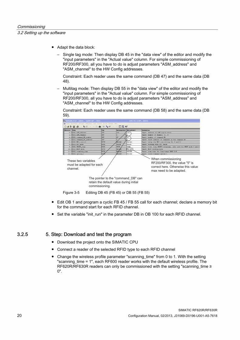
● Adapt the data block:
– Single tag mode: Then display DB 45 in the "data view" of the editor and modify the "input parameters" in the "Actual value" column. For simple commissioning of RF200/RF300, all you have to do is adjust parameters "ASM_address" and "ASM_channel" to the HW Config addresses.
Constraint: Each reader uses the same command (DB 47) and the same data (DB 48).
– Multitag mode: Then display DB 55 in the "data view" of the editor and modify the "input parameters" in the "Actual value" column. For simple commissioning of RF200/RF300, all you have to do is adjust parameters "ASM_address" and "ASM_channel" to the HW Config addresses.
Constraint: Each reader uses the same command (DB 58) and the same data (DB 59).
These two variablesmust be adapted for each channel.
The pointer to the "command_DB" can retain the default value during initial commissioning.
When commissioning RF200/RF300, the value "5" is correct here. Otherwise this value max need to be adapted.
Figure 3-5 Editing DB 45 (FB 45) or DB 55 (FB 55)
● Edit OB 1 and program a cyclic FB 45 / FB 55 call for each channel; declare a memory bit for the command start for each RFID channel.
● Set the variable "init_run" in the parameter DB in OB 100 for each RFID channel.
3.2.5 5. Step: Download and test the program ● Download the project onto the SIMATIC CPU
● Connect a reader of the selected RFID type to each RFID channel
● Change the wireless profile parameter "scanning_time" from 0 to 1. With the setting "scanning_time = 1", each RF600 reader works with the default wireless profile. The RF620R/RF630R readers can only be commissioned with the setting "scanning_time ≥ 0".
Commissioning 3.2 Setting up the software
SIMATIC RF620R/RF630R Configuration Manual, 02/2013, J31069-D0196-U001-A5-7618 21
● After restarting the SIMATIC CPU (STOP → RUN), the CPU must not change to STOP mode. If the CPU does indicate STOP, you should continue by troubleshooting. This is done by evaluating the diagnostic messages of the CPU (function: destination system - module status).
The main causes of errors are:
– There is a mismatch between the I/O address of the modules in HW Config and the "ASM_address" configured in the MOBY DB (UDT 10) or the "ASM_address" does not exist in the I/O.
– A slave has failed and OB 122 is not programmed.
● Since the default parameter assignment of FB 45 / FB 55 is set with "MDS_control = B#16#1, the presence check on the reader must already be active now. The RxD LED of the CM flickers and indicates active communication. If you now place a transponder in the antenna field of a reader, the PRE or ANW LED must light up. The LED on the reader also indicates presence.
If the RxD LED does not go on, continue with trouble-shooting as described in the next point.
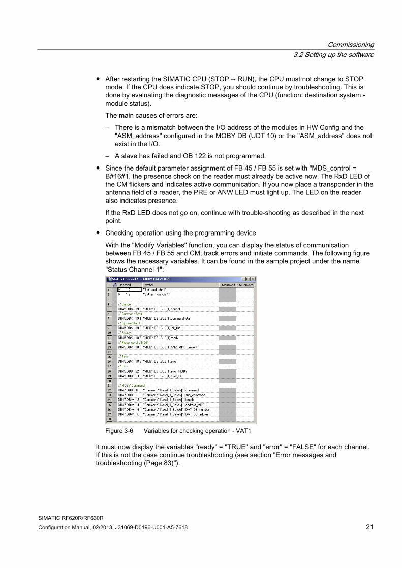
● Checking operation using the programming device
With the "Modify Variables" function, you can display the status of communication between FB 45 / FB 55 and CM, track errors and initiate commands. The following figure shows the necessary variables. It can be found in the sample project under the name "Status Channel 1":
Figure 3-6 Variables for checking operation - VAT1
It must now display the variables "ready" = "TRUE" and "error" = "FALSE" for each channel. If this is not the case continue troubleshooting (see section "Error messages and troubleshooting (Page 83)").
Commissioning 3.2 Setting up the software
SIMATIC RF620R/RF630R 22 Configuration Manual, 02/2013, J31069-D0196-U001-A5-7618
If "ready" = "FALSE":
● This channel is not called in OB 100.
● This channel is not processed cyclically by an FB 45 / FB 55 call in OB 1.
If "error" = "TRUE":
● Read out the precise cause of the error using the variables "error_MOBY", "error_FB" or "error_BUS". The error causes and their remedy are described in Section "Error messages and troubleshooting".
The variable "ANZ_MDS_present" now indicates the presence of a transponder as soon as you place a transponder in the antenna field of the reader. This is the same display as the PRE LED on the CM or the yellow LED on the reader.
You can now start the selected RFID command using the auxiliary variable "Befehl_starten" = "TRUE" . If there is no transponder in the reader's antenna field, the command remains active on the CM for an indefinite length of time.
This status is indicated by "ready" = "FALSE in the "Modify variables" window. Now, move a transponder into the antenna field. As soon as the transponder has been processed, the result is transferred to FB 45 / FB 55 and "ready" = "TRUE" is indicated.
● To start the reader, send an "init_run" to the reader from the controller via the CM.
Commissioning of the RFID components is now complete. You can now program your own Ident application based on the sample program.
SIMATIC RF620R/RF630R Configuration Manual, 02/2013, J31069-D0196-U001-A5-7618 23
Parameterizing 44.1 Overview of commands
SIMATIC blocks FB 45 and FB 55 provide various commands that can be used to access transponders and check reader settings.
Tag commands For access to a transponder, the following commands are available:
● INIT
Use this command to initialize the USER memory area of a transponder. In this case, this memory area is written with the desired bit pattern.
● READ
Use this command to read the addressed memory contents of a transponder.
● WRITE
Use this command to write data to the addressed memory area of a transponder or a reader.
● MDS-STATUS
Use this command to read the status and diagnostics data of a transponder.
● GET (available only with FB 55)
With the command, you detect all transponders in the antenna field of the reader in multitag mode.
Detailed information on the individual commands can be found in the following sections.
Reader commands The following commands are available for monitoring functions and settings on the reader:
● init_run
Use this command to define the operating mode of the reader and in particular the wireless standard, transmit power and speed. Displayed and reported errors are deleted.
● SLG-STATUS
Use this command to read the status and diagnostics information of the reader.
● SET-ANT
Use this command to switch the antenna of the reader on or off.
Parameterizing 4.1 Overview of commands
SIMATIC RF620R/RF630R 24 Configuration Manual, 02/2013, J31069-D0196-U001-A5-7618
Detailed information on the individual commands can be found in the following sections.
Note Reader commands are very complex
The Reader commands are very complex. To avoid unwanted results, read all the relevant sections on the reader commands before you work with these commands.
Command repetition Use the repeat command to repeat the last command. You can repeat the following commands:
● INIT
● READ
● WRITE
● MDS-STATUS
Command chaining Command chaining permits various address areas of the transponder to be processed by starting just one command. The advantage of command chaining is the optimum speed at which commands are processed in the reader.
You can chain the following commands:
● READ
● WRITE
● INIT
● GET
● SET-ANT
● MDS-STATUS
● SLG-STATUS
Parameterizing 4.2 FB 45 parameter assignment
SIMATIC RF620R/RF630R Configuration Manual, 02/2013, J31069-D0196-U001-A5-7618 25
4.2 FB 45 parameter assignment
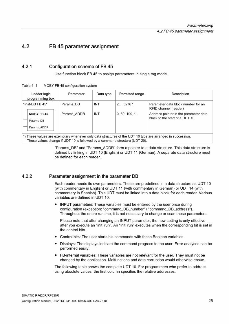
4.2.1 Configuration scheme of FB 45 Use function block FB 45 to assign parameters in single tag mode.
Table 4- 1 MOBY FB 45 configuration system
Ladder logic programming box
Parameter Data type Permitted range Description
"Inst-DB FB 45"
MOBY FB 45
Params_DB
Params_ADDR
Params_DB Params_ADDR
INT INT
2 ... 32767 0, 50, 100, *...
Parameter data block number for an RFID channel (reader) Address pointer in the parameter data block to the start of a UDT 10
*) These values are exemplary whenever only data structures of the UDT 10 type are arranged in succession. These values change if UDT 10 is followed by a command structure (UDT 20).
"Params_DB" and "Params_ADDR" form a pointer to a data structure. This data structure is defined by linking in UDT 10 (English) or UDT 11 (German). A separate data structure must be defined for each reader.
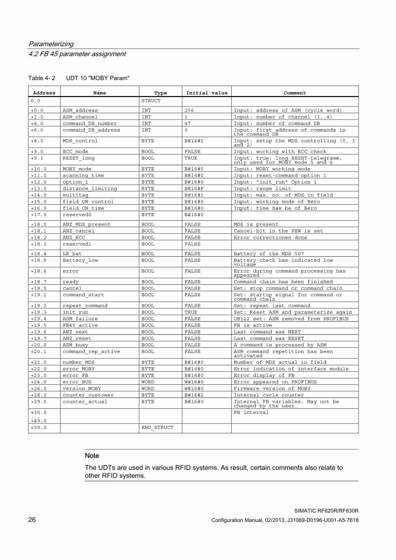
4.2.2 Parameter assignment in the parameter DB Each reader needs its own parameters. These are predefined in a data structure as UDT 10 (with commentary in English) or UDT 11 (with commentary in German) or UDT 14 (with commentary in Spanish). This UDT must be linked into a data block for each reader. Various variables are defined in UDT 10:
● INPUT parameters: These variables must be entered by the user once during configuration (exception: "command_DB_number" / "command_DB_address"). Throughout the entire runtime, it is not necessary to change or scan these parameters.
Please note that after changing an INPUT parameter, the new setting is only effective after you execute an "init_run". An "init_run" executes when the corresponding bit is set in the control bits.
● Control bits: The user starts his commands with these Boolean variables.
● Displays: The displays indicate the command progress to the user. Error analyses can be performed easily.
● FB-internal variables: These variables are not relevant for the user. They must not be changed by the application. Malfunctions and data corruption would otherwise ensue.
The following table shows the complete UDT 10. For programmers who prefer to address using absolute values, the first column specifies the relative addresses.
Parameterizing 4.2 FB 45 parameter assignment
SIMATIC RF620R/RF630R 26 Configuration Manual, 02/2013, J31069-D0196-U001-A5-7618
Table 4- 2 UDT 10 "MOBY Param"
Address Name Type Initial value Comment 0.0 STRUCT +0.0 ASM_address INT 256 Input: address of ASM (cycle word) +2.0 ASM_channel INT 1 Input: number of channel (1..4) +4.0 command_DB_number INT 47 Input: number of command DB +6.0 command_DB_address INT 0 Input: first address of commands in
the command DB +8.0 MDS_control BYTE B#16#1 Input: setup the MDS controlling (0, 1
and 2) +9.0 ECC_mode BOOL FALSE Input: working with ECC check +9.1 RESET_long BOOL TRUE Input: true: long RESET-telegramm,
only used for MOBY mode 5 and 6 +10.0 MOBY_mode BYTE B#16#5 Input: MOBY working mode +11.0 scanning_time BYTE B#16#0 Input: reset-command option 1 +12.0 option_1 BYTE B#16#0 Input: "init_run" Option 1 +13.0 distance_limiting BYTE B#16#F Input: range limit +14.0 multitag BYTE B#16#1 Input: max. no. of MDS in field +15.0 field_ON_control BYTE B#16#0 Input: working mode of Bero +16.0 field_ON_time BYTE B#16#0 Input: time has be of Bero +17.0 reserved0 BYTE B#16#0 +18.0 ANZ_MDS_present BOOL FALSE MDS is present +18.1 ANZ_cancel BOOL FALSE Cancel-bit in the PEW is set +18.2 ANZ_ECC BOOL FALSE Error correctionen done +18.3 reserved1 BOOL FALSE +18.4 LR_bat BOOL FALSE Battery of the MDS 507 +18.5 Battery_low BOOL FALSE Battery check has indicated low
voltage +18.6 error BOOL FALSE Error during command processing has
appeared +18.7 ready BOOL FALSE Command chain has been finished +19.0 cancel BOOL FALSE Set: stop command or command chain +19.1 command_start BOOL FALSE Set: startup signal for command or
command chain +19.2 repeat_command BOOL FALSE Set: repeat last command +19.3 init_run BOOL TRUE Set: Reset ASM and parameterize again +19.4 ASM_failure BOOL FALSE OB122 set: ASM removed from PROFIBUS +19.5 FB45_active BOOL FALSE FB is active +19.6 ANZ_next BOOL FALSE Last command was NEXT +19.7 ANZ_reset BOOL FALSE Last command was RESET +20.0 ASM_busy BOOL FALSE A command is processed by ASM +20.1 command_rep_active BOOL FALSE ASM command repetition has been
activated +21.0 number_MDS BYTE B#16#0 Number of MDS actual in field +22.0 error_MOBY BYTE B#16#0 Error indication of interface module +23.0 error_FB BYTE B#16#0 Error display of FB +24.0 error_BUS WORD W#16#0 Error appeared on PROFIBUS +26.0 version_MOBY WORD W#16#0 Firmware version of MOBY +28.0 counter_customer BYTE B#16#2 Internal cycle counter +29.0 counter_actual BYTE B#16#0 Internal FB variables. May not be
changed by the user. +30.0 ... +49.0
FB internal
=50.0 END_STRUCT
Note
The UDTs are used in various RFID systems. As result, certain comments also relate to other RFID systems.
Parameterizing 4.2 FB 45 parameter assignment
SIMATIC RF620R/RF630R Configuration Manual, 02/2013, J31069-D0196-U001-A5-7618 27
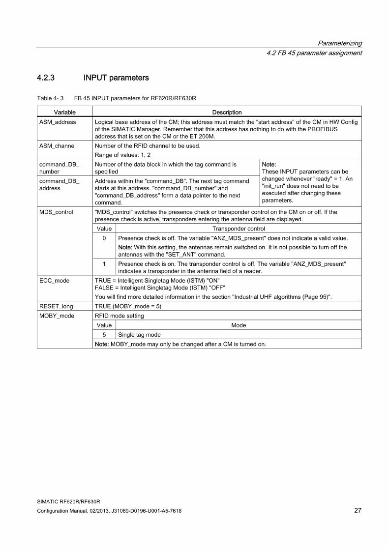
4.2.3 INPUT parameters
Table 4- 3 FB 45 INPUT parameters for RF620R/RF630R
Variable Description ASM_address Logical base address of the CM; this address must match the "start address" of the CM in HW Config
of the SIMATIC Manager. Remember that this address has nothing to do with the PROFIBUS address that is set on the CM or the ET 200M.
ASM_channel Number of the RFID channel to be used. Range of values: 1, 2
command_DB_ number
Number of the data block in which the tag command is specified
command_DB_ address
Address within the "command_DB". The next tag command starts at this address. "command_DB_number" and "command_DB_address" form a data pointer to the next command.
Note: These INPUT parameters can be changed whenever "ready" = 1. An "init_run" does not need to be executed after changing these parameters.
"MDS_control" switches the presence check or transponder control on the CM on or off. If the presence check is active, transponders entering the antenna field are displayed. Value Transponder control
0 Presence check is off. The variable "ANZ_MDS_present" does not indicate a valid value. Note: With this setting, the antennas remain switched on. It is not possible to turn off the antennas with the "SET_ANT" command.
MDS_control
1 Presence check is on. The transponder control is off. The variable "ANZ_MDS_present" indicates a transponder in the antenna field of a reader.
ECC_mode TRUE = Intelligent Singletag Mode (ISTM) "ON" FALSE = Intelligent Singletag Mode (ISTM) "OFF" You will find more detailed information in the section "Industrial UHF algorithms (Page 95)".
RESET_long TRUE (MOBY_mode = 5) RFID mode setting Value Mode
5 Single tag mode
MOBY_mode
Note: MOBY_mode may only be changed after a CM is turned on.
Parameterizing 4.2 FB 45 parameter assignment
SIMATIC RF620R/RF630R 28 Configuration Manual, 02/2013, J31069-D0196-U001-A5-7618
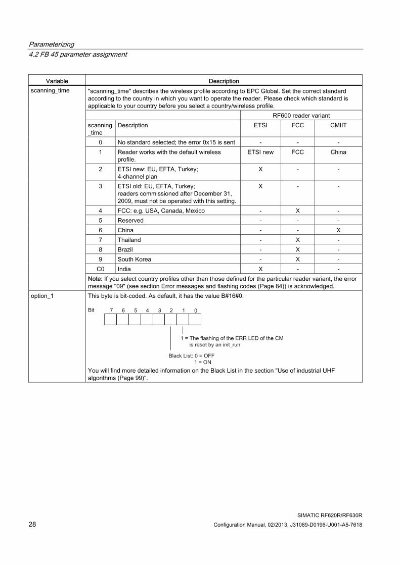
Variable Description "scanning_time" describes the wireless profile according to EPC Global. Set the correct standard according to the country in which you want to operate the reader. Please check which standard is applicable to your country before you select a country/wireless profile. RF600 reader variant scanning_time
Description ETSI FCC CMIIT
0 No standard selected; the error 0x15 is sent - - - 1 Reader works with the default wireless
profile. ETSI new FCC China
2 ETSI new: EU, EFTA, Turkey; 4-channel plan
X - -
3 ETSI old: EU, EFTA, Turkey; readers commissioned after December 31, 2009, must not be operated with this setting.
X - -
4 FCC: e.g. USA, Canada, Mexico - X - 5 Reserved - - - 6 China - - X 7 Thailand - X - 8 Brazil - X - 9 South Korea - X -
C0 India X - -
scanning_time
Note: If you select country profiles other than those defined for the particular reader variant, the error message "09" (see section Error messages and flashing codes (Page 84)) is acknowledged.
option_1 This byte is bit-coded. As default, it has the value B#16#0.
You will find more detailed information on the Black List in the section "Use of industrial UHF algorithms (Page 99)".
Parameterizing 4.2 FB 45 parameter assignment
SIMATIC RF620R/RF630R Configuration Manual, 02/2013, J31069-D0196-U001-A5-7618 29
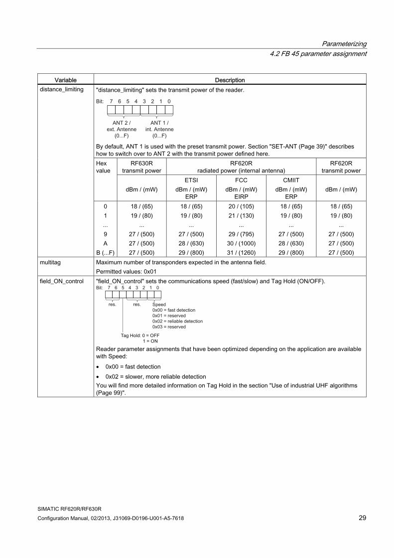
Variable Description "distance_limiting" sets the transmit power of the reader.
By default, ANT 1 is used with the preset transmit power. Section "SET-ANT (Page 39)" describes how to switch over to ANT 2 with the transmit power defined here.
RF630R transmit power
RF620R radiated power (internal antenna)
RF620R transmit power
Hex value
dBm / (mW)
ETSI dBm / (mW)
ERP
FCC dBm / (mW)
EIRP
CMIIT dBm / (mW)
ERP
dBm / (mW)
distance_limiting
0 1 ... 9 A
B (...F)
18 / (65) 19 / (80)
... 27 / (500) 27 / (500) 27 / (500)
18 / (65) 19 / (80)
... 27 / (500) 28 / (630) 29 / (800)
20 / (105) 21 / (130)
... 29 / (795) 30 / (1000) 31 / (1260)
18 / (65) 19 / (80)
... 27 / (500) 28 / (630) 29 / (800)
18 / (65) 19 / (80)
... 27 / (500) 27 / (500) 27 / (500)
multitag Maximum number of transponders expected in the antenna field. Permitted values: 0x01
field_ON_control "field_ON_control" sets the communications speed (fast/slow) and Tag Hold (ON/OFF).
Reader parameter assignments that have been optimized depending on the application are available with Speed: • 0x00 = fast detection • 0x02 = slower, more reliable detection You will find more detailed information on Tag Hold in the section "Use of industrial UHF algorithms (Page 99)".
Parameterizing 4.2 FB 45 parameter assignment
SIMATIC RF620R/RF630R 30 Configuration Manual, 02/2013, J31069-D0196-U001-A5-7618
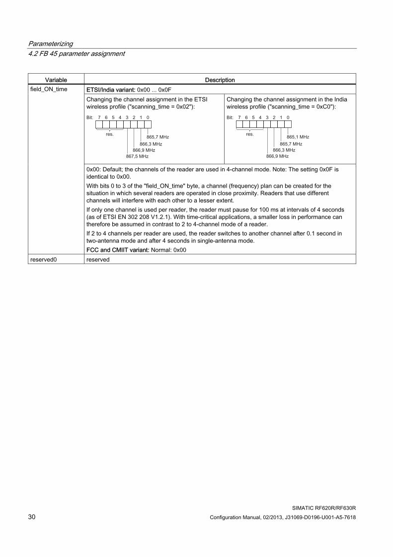
Variable Description ETSI/India variant: 0x00 ... 0x0F Changing the channel assignment in the ETSI wireless profile ("scanning_time = 0x02"):
Changing the channel assignment in the India wireless profile ("scanning_time = 0xC0"):
field_ON_time
0x00: Default; the channels of the reader are used in 4-channel mode. Note: The setting 0x0F is identical to 0x00. With bits 0 to 3 of the "field_ON_time" byte, a channel (frequency) plan can be created for the situation in which several readers are operated in close proximity. Readers that use different channels will interfere with each other to a lesser extent. If only one channel is used per reader, the reader must pause for 100 ms at intervals of 4 seconds (as of ETSI EN 302 208 V1.2.1). With time-critical applications, a smaller loss in performance can therefore be assumed in contrast to 2 to 4-channel mode of a reader. If 2 to 4 channels per reader are used, the reader switches to another channel after 0.1 second in two-antenna mode and after 4 seconds in single-antenna mode. FCC and CMIIT variant: Normal: 0x00
reserved0 reserved
Parameterizing 4.2 FB 45 parameter assignment
SIMATIC RF620R/RF630R Configuration Manual, 02/2013, J31069-D0196-U001-A5-7618 31
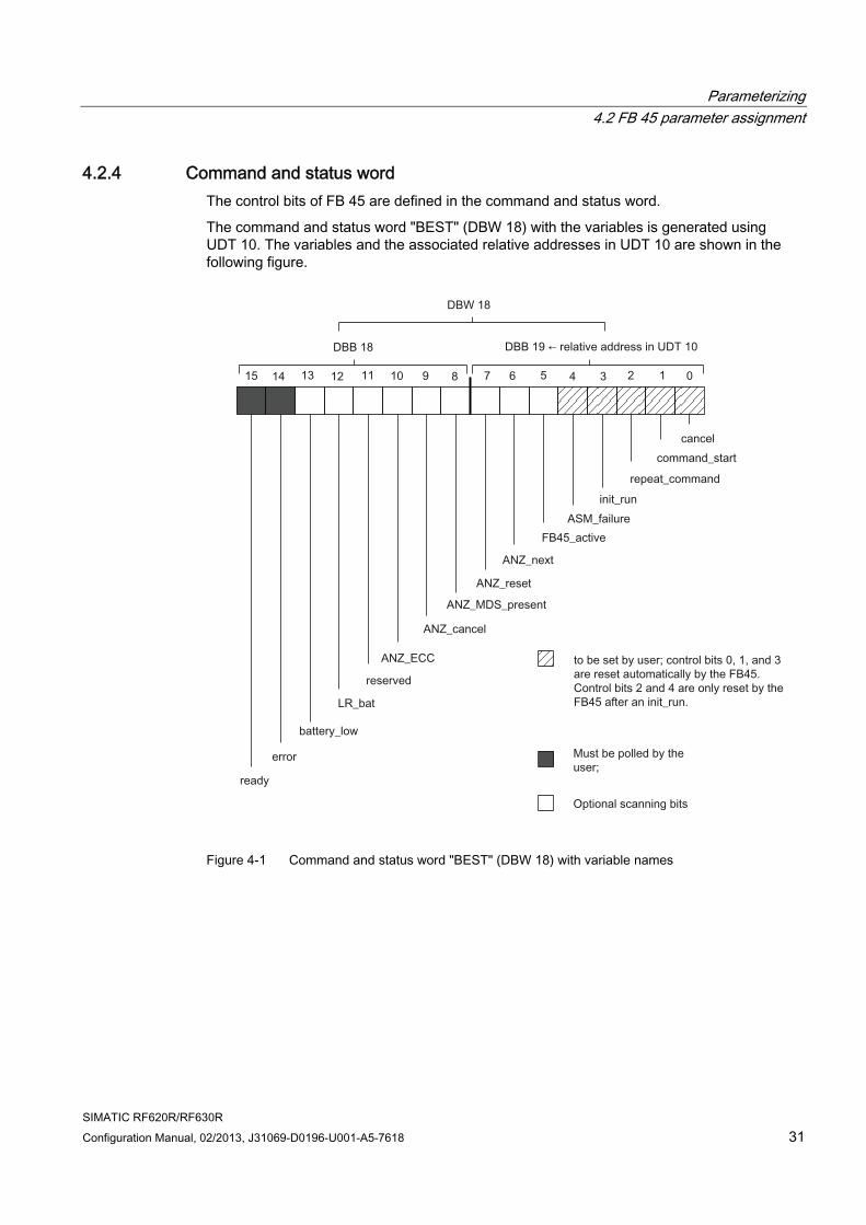
4.2.4 Command and status word The control bits of FB 45 are defined in the command and status word.
The command and status word "BEST" (DBW 18) with the variables is generated using UDT 10. The variables and the associated relative addresses in UDT 10 are shown in the following figure.
Figure 4-1 Command and status word "BEST" (DBW 18) with variable names
Parameterizing 4.2 FB 45 parameter assignment
SIMATIC RF620R/RF630R 32 Configuration Manual, 02/2013, J31069-D0196-U001-A5-7618
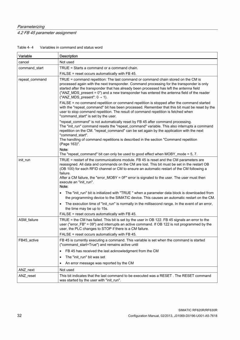
Table 4- 4 Variables in command and status word
Variable Description cancel Not used command_start TRUE = Starts a command or a command chain.
FALSE = reset occurs automatically with FB 45. repeat_command TRUE = command repetition: The last command or command chain stored on the CM is
processed again with the next transponder. Command processing for the transponder is only started after the transponder that has already been processed has left the antenna field ("ANZ_MDS_present = 0") and a new transponder has entered the antenna field of the reader ("ANZ_MDS_present": 0 → 1). FALSE = no command repetition or command repetition is stopped after the command started with the "repeat_command" bit has been processed. Remember that this bit must be reset by the user to stop command repetition. The result of command repetition is fetched when "command_start" is set by the user. "repeat_command" is not automatically reset by FB 45 after command processing. The "init_run" command resets the "repeat_command" variable. This also interrupts a command repetition on the CM. "repeat_command" can be set again by the application with the next "command_start". The handling of command repetitions is described in the section "Command repetition (Page 163)". Note: The "repeat_command" bit can only be used to good effect when MOBY_mode = 5, 7.
init_run TRUE = restart of the communications module. FB 45 is reset and the CM parameters are reassigned. All data and commands on the CM are lost. This bit must be set in the restart OB (OB 100) for each RFID channel or CM to ensure an automatic restart of the CM following a failure. After a CM failure, the "error_MOBY = 0F" error is signaled to the user. The user must then execute an "init_run". Note: • The "init_run" bit is initialized with "TRUE " when a parameter data block is downloaded from
the programming device to the SIMATIC device. This causes an automatic restart on the CM. • The execution time of "init_run" is normally in the millisecond range. In the event of an error,
the time may be up to 15s. FALSE = reset occurs automatically with FB 45.
ASM_failure TRUE = the CM has failed. This bit is set by the user in OB 122. FB 45 signals an error to the user ("error_FB" = 09") and interrupts an active command. If OB 122 is not programmed by the user, the PLC changes to STOP if there is a CM failure. FALSE = reset occurs automatically with FB 45.
FB45_active FB 45 is currently executing a command. This variable is set when the command is started ("command_start=True") and remains active until • FB 45 has received the last acknowledgment from the CM • The "init_run" bit was set • An error message was reported by the CM
ANZ_next Not used ANZ_reset This bit indicates that the last command to be executed was a RESET . The RESET command
was started by the user with "init_run".
Parameterizing 4.2 FB 45 parameter assignment
SIMATIC RF620R/RF630R Configuration Manual, 02/2013, J31069-D0196-U001-A5-7618 33
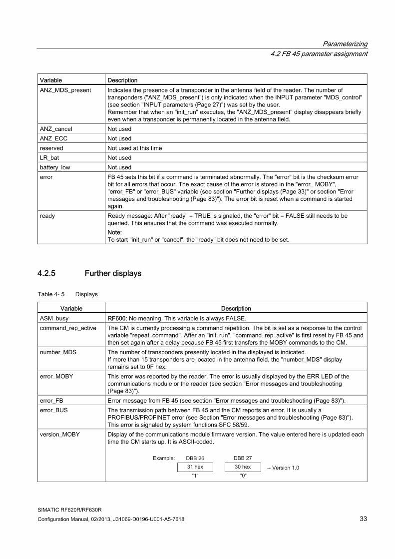
Variable Description ANZ_MDS_present Indicates the presence of a transponder in the antenna field of the reader. The number of
transponders ("ANZ_MDS_present") is only indicated when the INPUT parameter "MDS_control" (see section "INPUT parameters (Page 27)") was set by the user. Remember that when an "init_run" executes, the "ANZ_MDS_present" display disappears briefly even when a transponder is permanently located in the antenna field.
ANZ_cancel Not used ANZ_ECC Not used reserved Not used at this time LR_bat Not used battery_low Not used error FB 45 sets this bit if a command is terminated abnormally. The "error" bit is the checksum error
bit for all errors that occur. The exact cause of the error is stored in the "error_ MOBY", "error_FB" or "error_BUS" variable (see section "Further displays (Page 33)" or section "Error messages and troubleshooting (Page 83)"). The error bit is reset when a command is started again.
ready Ready message: After "ready" = TRUE is signaled, the "error" bit = FALSE still needs to be queried. This ensures that the command was executed normally. Note: To start "init_run" or "cancel", the "ready" bit does not need to be set.
4.2.5 Further displays
Table 4- 5 Displays
Variable Description ASM_busy RF600: No meaning. This variable is always FALSE. command_rep_active The CM is currently processing a command repetition. The bit is set as a response to the control
variable "repeat_command". After an "init_run", "command_rep_active" is first reset by FB 45 and then set again after a delay because FB 45 first transfers the MOBY commands to the CM.
number_MDS The number of transponders presently located in the displayed is indicated. If more than 15 transponders are located in the antenna field, the "number_MDS" display remains set to 0F hex.
error_MOBY This error was reported by the reader. The error is usually displayed by the ERR LED of the communications module or the reader (see section "Error messages and troubleshooting (Page 83)").
error_FB Error message from FB 45 (see section "Error messages and troubleshooting (Page 83)"). error_BUS The transmission path between FB 45 and the CM reports an error. It is usually a
PROFIBUS/PROFINET error (see Section "Error messages and troubleshooting (Page 83)"). This error is signaled by system functions SFC 58/59.
version_MOBY Display of the communications module firmware version. The value entered here is updated each time the CM starts up. It is ASCII-coded.
Parameterizing 4.2 FB 45 parameter assignment
SIMATIC RF620R/RF630R 34 Configuration Manual, 02/2013, J31069-D0196-U001-A5-7618
All other variables of UDT 10 are for FB-internal use. They must never be changed by the user.
4.2.6 RFID commands of FB 45
Note
This section provides a description of all commands that can by processed by FB 45.
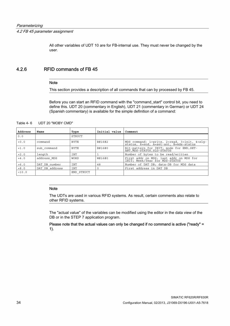
Before you can start an RFID command with the "command_start" control bit, you need to define this. UDT 20 (commentary in English), UDT 21 (commentary in German) or UDT 24 (Spanish commentary) is available for the simple definition of a command:
Table 4- 6 UDT 20 "MOBY CMD"
Address Name Type Initial value Comment 0.0 STRUCT +0.0 command BYTE B#16#2 MDS command: 1=write, 2=read, 3=init, 4=slg-
status, 8=end, A=set-ant, B=mds-status +1.0 sub_command BYTE B#16#0 Bit-pattern for INIT; mode for END,SET-
ANT,MDS-STATUS,SLG-STATUS +2.0 length INT 1 Number of bytes to be read/written +4.0 address_MDS WORD W#16#0 First addr on MDS; last addr on MDS for
INIT; Week/Year for MDS-STATUS +6.0 DAT_DB_number INT 48 Number of DAT DB; data-DB for MDS data +8.0 DAT_DB_address INT 0 First address in DAT DB =10.0 END_STRUCT
Note
The UDTs are used in various RFID systems. As result, certain comments also relate to other RFID systems.
The "actual value" of the variables can be modified using the editor in the data view of the DB or in the STEP 7 application program.
Please note that the actual values can only be changed if no command is active ("ready" = 1).
Parameterizing 4.2 FB 45 parameter assignment
SIMATIC RF620R/RF630R Configuration Manual, 02/2013, J31069-D0196-U001-A5-7618 35
4.2.7 Parameter assignment of the commands with FB 45
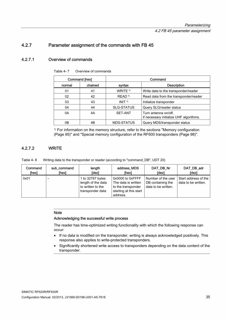
4.2.7.1 Overview of commands
Table 4- 7 Overview of commands
Command [hex] Command normal chained syntax Description
01 41 WRITE 1) Write data to the transponder/reader 02 42 READ 1) Read data from the transponder/reader 03 43 INIT 1) Initialize transponder 04 44 SLG-STATUS Query SLG/reader status 0A 4A SET-ANT Turn antenna on/off,
if necessary initialize UHF algorithms. 0B 4B MDS-STATUS Query MDS/transponder status
1) For information on the memory structure, refer to the sections "Memory configuration (Page 95)" and "Special memory configuration of the RF600 transponders (Page 98)".
4.2.7.2 WRITE
Table 4- 8 Writing data to the transponder or reader (according to "command_DB", UDT 20)
Command [hex]
sub_command [hex]
length [dez]
address_MDS [hex]
DAT_DB_Nr [dez]
DAT_DB_adr [dez]
0x01 – 1 to 32767 bytes length of the data to written to the transponder data
0x0000 to 0xFFFF The data is written to the transponder starting at this start address.
Number of the user DB containing the data to be written.
Start address of the data to be written.
Note Acknowledging the successful write process
The reader has time-optimized writing functionality with which the following response can occur: • If no data is modified on the transponder, writing is always acknowledged positively. This
response also applies to write-protected transponders. • Significantly shortened write access to transponders depending on the data content of the
transponder.
Parameterizing 4.2 FB 45 parameter assignment
SIMATIC RF620R/RF630R 36 Configuration Manual, 02/2013, J31069-D0196-U001-A5-7618
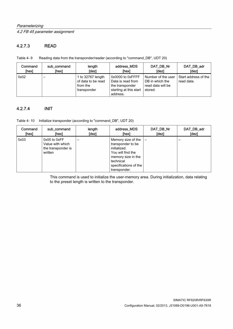
4.2.7.3 READ
Table 4- 9 Reading data from the transponder/reader (according to "command_DB", UDT 20)
Command [hex]
sub_command [hex]
length [dez]
address_MDS [hex]
DAT_DB_Nr [dez]
DAT_DB_adr [dez]
0x02 – 1 to 32767 length of data to be read from the transponder
0x0000 to 0xFFFF Data is read from the transponder starting at this start address.
Number of the user DB in which the read data will be stored.
Start address of the read data.
4.2.7.4 INIT
Table 4- 10 Initialize transponder (according to "command_DB", UDT 20)
Command [hex]
sub_command [hex]
length [dez]
address_MDS [hex]
DAT_DB_Nr [dez]
DAT_DB_adr [dez]
0x03 0x00 to 0xFF Value with which the transponder is written
– Memory size of the transponder to be initialized. You will find the memory size in the technical specifications of the transponder.
– –
This command is used to initialize the user-memory area. During initialization, data relating to the preset length is written to the transponder.
Parameterizing 4.2 FB 45 parameter assignment
SIMATIC RF620R/RF630R Configuration Manual, 02/2013, J31069-D0196-U001-A5-7618 37
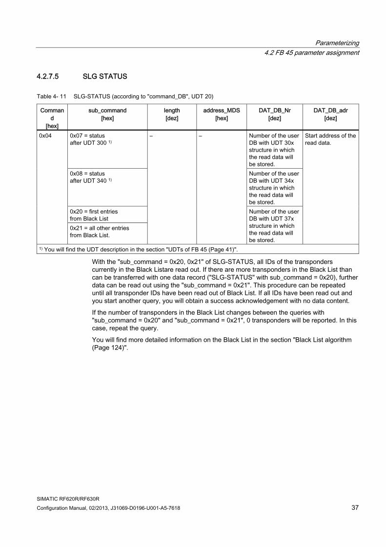
4.2.7.5 SLG STATUS
Table 4- 11 SLG-STATUS (according to "command_DB", UDT 20)
Command
[hex]
sub_command [hex]
length [dez]
address_MDS [hex]
DAT_DB_Nr [dez]
DAT_DB_adr [dez]
0x07 = status after UDT 300 1)
Number of the user DB with UDT 30x structure in which the read data will be stored.
0x08 = status after UDT 340 1)
Number of the user DB with UDT 34x structure in which the read data will be stored.
0x20 = first entries from Black List
0x04
0x21 = all other entries from Black List.
– –
Number of the user DB with UDT 37x structure in which the read data will be stored.
Start address of the read data.
1) You will find the UDT description in the section "UDTs of FB 45 (Page 41)".
With the "sub_command = 0x20, 0x21" of SLG-STATUS, all IDs of the transponders currently in the Black Listare read out. If there are more transponders in the Black List than can be transferred with one data record ("SLG-STATUS" with sub_command = 0x20), further data can be read out using the "sub_command = 0x21". This procedure can be repeated until all transponder IDs have been read out of Black List. If all IDs have been read out and you start another query, you will obtain a success acknowledgement with no data content.
If the number of transponders in the Black List changes between the queries with "sub_command = 0x20" and "sub_command = 0x21", 0 transponders will be reported. In this case, repeat the query.
You will find more detailed information on the Black List in the section "Black List algorithm (Page 124)".
Parameterizing 4.2 FB 45 parameter assignment
SIMATIC RF620R/RF630R 38 Configuration Manual, 02/2013, J31069-D0196-U001-A5-7618
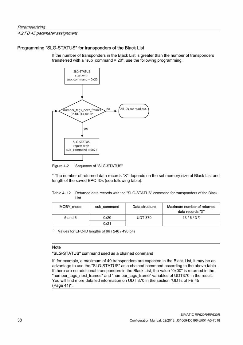
Programming "SLG-STATUS" for transponders of the Black List If the number of transponders in the Black List is greater than the number of transponders transferred with a "sub_command = 20", use the following programming.
SLG-STATUS start with
sub_command = 0x20
SLG-STATUS repeat with
sub_command = 0x21
All IDs are read out.number_tags_next_frames(in UDT) > 0x00*
no
yes
Figure 4-2 Sequence of "SLG-STATUS"
* The number of returned data records "X" depends on the set memory size of Black List and length of the saved EPC-IDs (see following table).
Table 4- 12 Returned data records with the "SLG-STATUS" command for transponders of the Black List
MOBY_mode sub_command Data structure Maximum number of returned data records "X"
0x20 5 and 6 0x21
UDT 370 13 / 6 / 3 1)
1) Values for EPC-ID lengths of 96 / 240 / 496 bits
Note "SLG-STATUS" command used as a chained command
If, for example, a maximum of 40 transponders are expected in the Black List, it may be an advantage to use the "SLG-STATUS" as a chained command according to the above table. If there are no additional transponders in the Black List, the value "0x00" is returned in the "number_tags_next_frames" and "number_tags_frame" variables of UDT370 in the result. You will find more detailed information on UDT 370 in the section "UDTs of FB 45 (Page 41)".
Parameterizing 4.2 FB 45 parameter assignment
SIMATIC RF620R/RF630R Configuration Manual, 02/2013, J31069-D0196-U001-A5-7618 39
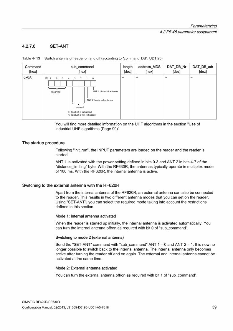
4.2.7.6 SET-ANT
Table 4- 13 Switch antenna of reader on and off (according to "command_DB", UDT 20)
Command [hex]
sub_command [hex]
length[dez]
address_MDS[hex]
DAT_DB_Nr [dez]
DAT_DB_adr[dez]
0x0A – – – –
You will find more detailed information on the UHF algorithms in the section "Use of industrial UHF algorithms (Page 99)".
The startup procedure Following "init_run", the INPUT parameters are loaded on the reader and the reader is started:
ANT 1 is activated with the power setting defined in bits 0-3 and ANT 2 in bits 4-7 of the "distance_limiting" byte. With the RF630R, the antennas typically operate in multiplex mode of 100 ms. With the RF620R, the internal antenna is active.
Switching to the external antenna with the RF620R Apart from the internal antenna of the RF620R, an external antenna can also be connected to the reader. This results in two different antenna modes that you can set on the reader. Using "SET-ANT", you can select the required mode taking into account the restrictions defined in this section.
Mode 1: Internal antenna activated
When the reader is started up initially, the internal antenna is activated automatically. You can turn the internal antenna off/on as required with bit 0 of "sub_command".
Switching to mode 2 (external antenna)
Send the "SET-ANT" command with "sub_command" ANT 1 = 0 and ANT 2 = 1. It is now no longer possible to switch back to the internal antenna. The internal antenna only becomes active after turning the reader off and on again. The external and internal antenna cannot be activated at the same time.
Mode 2: External antenna activated
You can turn the external antenna off/on as required with bit 1 of "sub_command".
Parameterizing 4.2 FB 45 parameter assignment
SIMATIC RF620R/RF630R 40 Configuration Manual, 02/2013, J31069-D0196-U001-A5-7618
External antenna of RF630R
Note If only one antenna is connected to the RF630R reader:
After an "init_run", both antennas of the RF630R are switched on.
If you have connected only one antenna, switch off the antenna that is not connected immediately after the "init_run" using the "SET-ANT" command or the reader will report an error.
If the "SET-ANT" command to switch off the antenna is not sent before the read/write commands are sent, the reader must be restarted with "init_run".
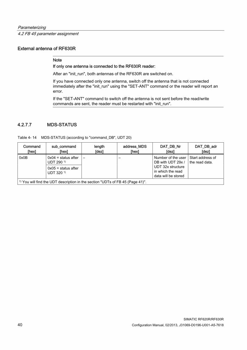
4.2.7.7 MDS-STATUS
Table 4- 14 MDS-STATUS (according to "command_DB", UDT 20)
Command [hex]
sub_command [hex]
length [dez]
address_MDS [hex]
DAT_DB_Nr [dez]
DAT_DB_adr [dez]
0x04 = status after UDT 290 1)
0x0B
0x05 = status after UDT 320 1)
– – Number of the user DB with UDT 29x / UDT 32x structure in which the read data will be stored
Start address of the read data.
1) You will find the UDT description in the section "UDTs of FB 45 (Page 41)".
Parameterizing 4.2 FB 45 parameter assignment
SIMATIC RF620R/RF630R Configuration Manual, 02/2013, J31069-D0196-U001-A5-7618 41
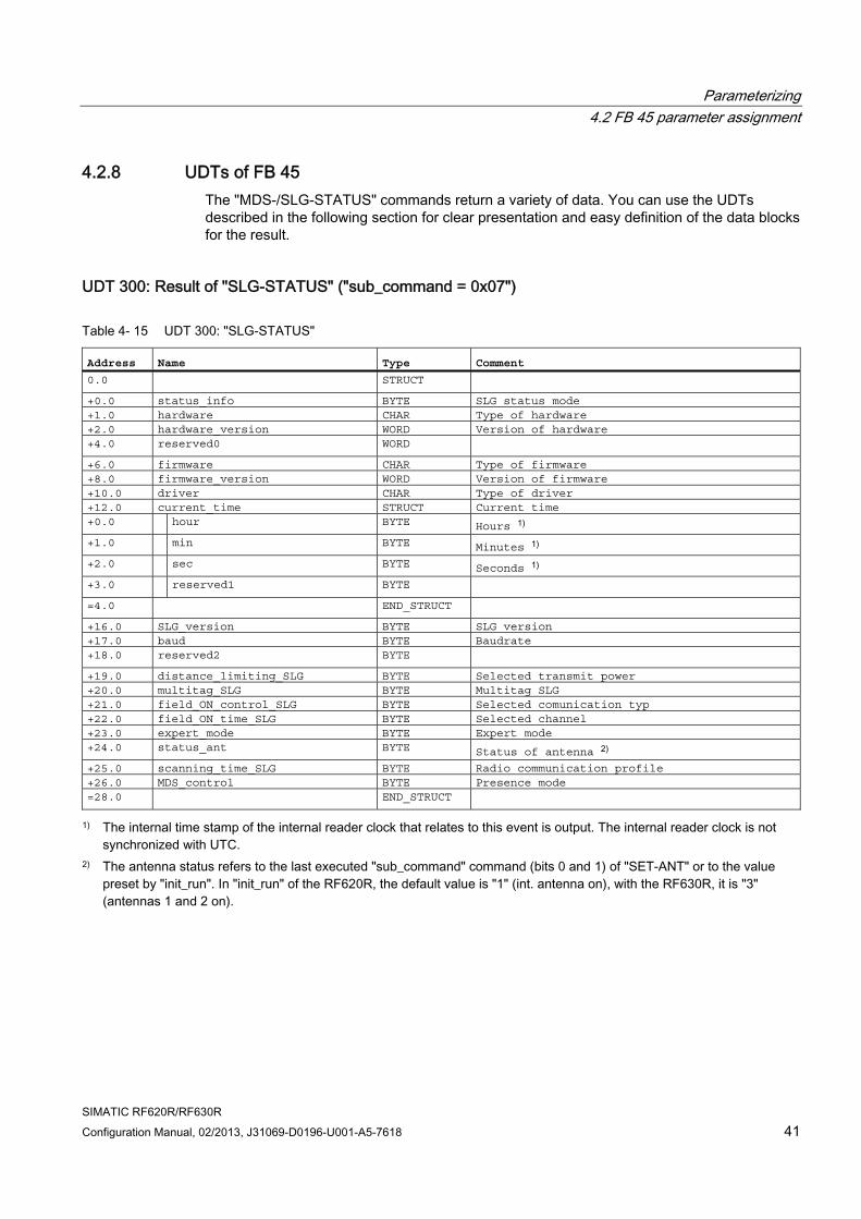
4.2.8 UDTs of FB 45 The "MDS-/SLG-STATUS" commands return a variety of data. You can use the UDTs described in the following section for clear presentation and easy definition of the data blocks for the result.
UDT 300: Result of "SLG-STATUS" ("sub_command = 0x07")
Table 4- 15 UDT 300: "SLG-STATUS"
Address Name Type Comment 0.0 STRUCT +0.0 status_info BYTE SLG status mode +1.0 hardware CHAR Type of hardware +2.0 hardware_version WORD Version of hardware +4.0 reserved0 WORD +6.0 firmware CHAR Type of firmware +8.0 firmware_version WORD Version of firmware +10.0 driver CHAR Type of driver +12.0 current_time STRUCT Current time +0.0 hour BYTE Hours 1) +1.0 min BYTE Minutes 1) +2.0 sec BYTE Seconds 1) +3.0 reserved1 BYTE =4.0 END_STRUCT +16.0 SLG_version BYTE SLG version +17.0 baud BYTE Baudrate +18.0 reserved2 BYTE +19.0 distance_limiting_SLG BYTE Selected transmit power +20.0 multitag_SLG BYTE Multitag SLG +21.0 field_ON_control_SLG BYTE Selected comunication typ +22.0 field_ON_time_SLG BYTE Selected channel +23.0 expert_mode BYTE Expert mode +24.0 status_ant BYTE Status of antenna 2) +25.0 scanning_time_SLG BYTE Radio communication profile +26.0 MDS_control BYTE Presence mode =28.0 END_STRUCT
1) The internal time stamp of the internal reader clock that relates to this event is output. The internal reader clock is not synchronized with UTC.
2) The antenna status refers to the last executed "sub_command" command (bits 0 and 1) of "SET-ANT" or to the value preset by "init_run". In "init_run" of the RF620R, the default value is "1" (int. antenna on), with the RF630R, it is "3" (antennas 1 and 2 on).

Parameterizing 4.2 FB 45 parameter assignment
SIMATIC RF620R/RF630R 42 Configuration Manual, 02/2013, J31069-D0196-U001-A5-7618
UDT 340: Result of "SLG-STATUS" ("sub_command = 0x08")
Table 4- 16 UDT 340: "SLG-STATUS"
Address Name Type Comment 0.0 STRUCT +0.0 status_info BYTE SLG-Status mode(Subcommand)
+1.0 hardware CHAR Type of hardware
+2.0 hardware_version WORD Version of hardware
+4.0 reserved_word1 WORD Reserved
+6.0 firmware CHAR Type of firmware
+7.0 firmware_version_HB BYTE Version of firmware (High-Byte)
+8.0 firmware_version_LB BYTE Version of firmware (Low-Byte)
+9.0 driver CHAR Type of driver
+10.0 current_time_hour BYTE Hours 1)
+11.0 current_time_minute BYTE Minutes 1)
+12.0 current_time_sek BYTE Seconds 1)
+13.0 current_time_reservByte BYTE
+14.0 SLG_version BYTE SLG-Version
+15.0 baud BYTE Baudrate
+16.0 reserved_byte1 BYTE Reserved
+17.0 distance_limiting_SLG BYTE Selected transmit power
+18.0 multitag_SLG BYTE Multitag SLG
+19.0 field_ON_control_SLG BYTE Selected communication type
+20.0 field_ON_time_SLG BYTE Selected channel
+21.0 expert_mode BYTE Expert mode
+22.0 status_ant BYTE Status of antenna 2)
+23.0 scanning_time_SLG BYTE Radio communication profile (country
specific radio standard)
+24.0 MDS_control BYTE Precence mode
+25.0 blink_pattern BYTE Blink Pattern
+26.0 activated_algorithms STRUCT Information on currently selected
algorithms
+0.0 Single_Tag FALSE Single_Tag [1]
+0.1 ITF_Phase2 FALSE ITF_Phase2 [2]
+0.2 ITF_Phase1 FALSE ITF_Phase1 [3]
+0.3 Smoothing FALSE Smoothing [4]
+0.4 Blacklist FALSE Blacklist [5]
+0.5 RSSI_Threshold FALSE RSSI_Threshold [6]
+0.6 Power_Ramp FALSE Power_Ramp [7]
+0.7 Power_Gap FALSE Power_Gap [8]
+1.0 Reserved1 FALSE Reserved1 [1]
+1.1 Reserved2 FALSE Reserved2 [2]
+1.2 Reserved3 FALSE Reserved3 [3]
+1.3 Reserved4 FALSE Reserved4 [4]
+1.4 EPC_MemBankFilter FALSE EPC_MemBankFilter [5]
+1.5 Tag_Hold FALSE Tag_Hold [6]

Parameterizing 4.2 FB 45 parameter assignment
SIMATIC RF620R/RF630R Configuration Manual, 02/2013, J31069-D0196-U001-A5-7618 43
Address Name Type Comment +1.6 Multi_Tag FALSE Multi_Tag [7]
+1.7 ISTM FALSE ISTM [8]
=2.0 END_STRUCT +28.0 reserved_word2 WORD Reserved
+30.0 reserved_word3 WORD Reserved
+32.0 reserved_word4 WORD Reserved
+34.0 filtered_max_rssi BYTE Maximum RSSI value of a tag, of all
filtered tags
+35.0 reserved_byte2 BYTE Reserved
+36.0 filtered_tags_rssi BYTE Number of tags, filtered out by the RSSI
threshold
+37.0 reserved_byte3 BYTE Reserved
+38.0 filtered_tags_black_list WORD Number of tags, filtered out via Black
List
+40.0 filtered_tags_epc_data WORD Number of tags, filtered out via EPC
Data Filter
+42.0 filtered_tags_smoothing WORD Number of tags in Tag List of status Not
Observed
+44.0 itf_ph1_max_detect WORD Number of reads of a Tag, filtered out
via ITF phase 1
+46.0 itf_ph1_tags_detect WORD Number of tags, filtered out via ITF
phase 1
+48.0 itf_ph2_max_detect WORD Number of reads of a Tag, filtered out
via ITF phase 2
+50.0 itf_ph2_tags_detect WORD Number of tags, filtered out via ITF
phase 2
+52.0 filtered_istm_min_dist WORD Minimum distance of Tags according to
sorting criterion of ISTM
+54.0 filtered_istm_tags WORD Number of tags, filtered out via ISTM
algorithm
+56.0 last_error BYTE error code of the last occuring error
(last_command)
+57.0 reserved_byte4 BYTE Reserved
+58.0 error_command1 WORD Last command (has lead to error code)
"last_error"
+60.0 error_command2 WORD Last command (has lead to error code)
"last_error"
+62.0 error_command3 WORD Last command (has lead to error code)
"last_error"
+64.0 reserved_word5 WORD Reserved
+66.0 reserved_array_byte ARRAY[1...
30]
*1.0 BYTE =96.0 END_STRUCT
Parameterizing 4.2 FB 45 parameter assignment
SIMATIC RF620R/RF630R 44 Configuration Manual, 02/2013, J31069-D0196-U001-A5-7618
1) The internal time stamp of the internal reader clock that relates to this event is output. The internal reader clock is not synchronized with UTC. 2) The antenna status refers to the "sub_command" (bits 0 and 1) of "SET-ANT" or to the value preset by "init_run". In "init_run" of the RF620R, the default value is "1" (int. antenna on), with the RF630R, it is "3" (antennas 1 and 2 on).
Note Information on the UDTs in addresses +25 to +62
The meaning and use of the variables in addresses +25 to +62 is explained in the section "Status display of industrial UHF algorithms using of SLG-STATUS (Page 106)".
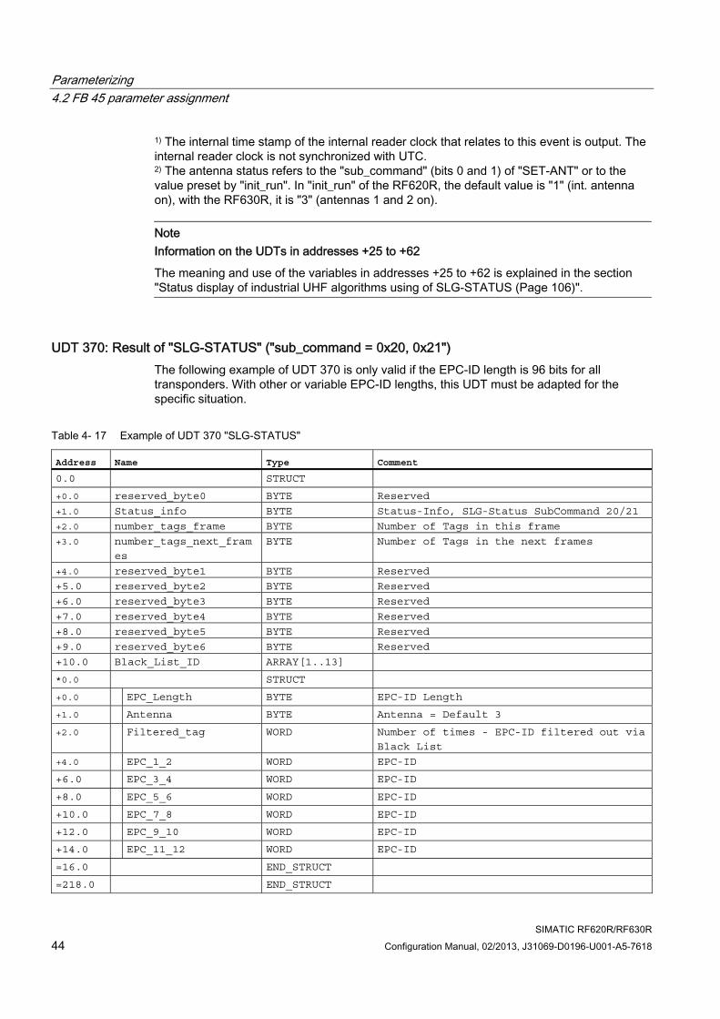
UDT 370: Result of "SLG-STATUS" ("sub_command = 0x20, 0x21") The following example of UDT 370 is only valid if the EPC-ID length is 96 bits for all transponders. With other or variable EPC-ID lengths, this UDT must be adapted for the specific situation.
Table 4- 17 Example of UDT 370 "SLG-STATUS"
Address Name Type Comment 0.0 STRUCT +0.0 reserved_byte0 BYTE Reserved
+1.0 Status_info BYTE Status-Info, SLG-Status SubCommand 20/21
+2.0 number_tags_frame BYTE Number of Tags in this frame
+3.0 number_tags_next_fram
es
BYTE Number of Tags in the next frames
+4.0 reserved_byte1 BYTE Reserved
+5.0 reserved_byte2 BYTE Reserved
+6.0 reserved_byte3 BYTE Reserved
+7.0 reserved_byte4 BYTE Reserved
+8.0 reserved_byte5 BYTE Reserved
+9.0 reserved_byte6 BYTE Reserved
+10.0 Black_List_ID ARRAY[1..13] *0.0 STRUCT +0.0 EPC_Length BYTE EPC-ID Length
+1.0 Antenna BYTE Antenna = Default 3
+2.0 Filtered_tag WORD Number of times - EPC-ID filtered out via
Black List
+4.0 EPC_1_2 WORD EPC-ID
+6.0 EPC_3_4 WORD EPC-ID
+8.0 EPC_5_6 WORD EPC-ID
+10.0 EPC_7_8 WORD EPC-ID
+12.0 EPC_9_10 WORD EPC-ID
+14.0 EPC_11_12 WORD EPC-ID
=16.0 END_STRUCT =218.0 END_STRUCT
Parameterizing 4.2 FB 45 parameter assignment
SIMATIC RF620R/RF630R Configuration Manual, 02/2013, J31069-D0196-U001-A5-7618 45
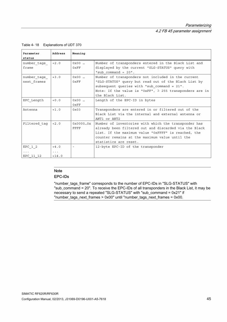
Table 4- 18 Explanations of UDT 370
Parameter
status Address Meaning
number_tags_
frame
+2.0 0x00 …
0xFF
Number of transponders entered in the Black List and
displayed by the current "SLG-STATUS" query with
"sub_command = 20".
number_tags_
next_frames
+3.0 0x00 …
0xFF
Number of transponders not included in the current
"SLG-STATUS" query but read out of the Black List by
subsequent queries with "sub_command = 21".
Note: If the value is "0xFF", ≥ 255 transponders are in the Black List.
EPC_Length +0.0 0x00 …
0xFF
Length of the EPC-ID in bytes
Antenna +1.0 0x03
Transponders are entered in or filtered out of the
Black List via the internal and external antenna or
ANT1 or ANT2
Filtered_tag +2.0 0x0000…0x
FFFF
Number of inventories with which the transponder has
already been filtered out and discarded via the Black
List. If the maximum value "0xFFFF" is reached, the
counter remains at the maximum value until the
statistics are reset.
EPC_1_2
...
EPC_11_12
+4.0
...
+14.0
- 12-byte EPC-ID of the transponder
Note EPC-IDs
"number_tags_frame" corresponds to the number of EPC-IDs in "SLG-STATUS" with "sub_command = 20". To receive the EPC-IDs of all transponders in the Black List, it may be necessary to send a repeated "SLG-STATUS" with "sub_command = 0x21" if "number_tags_next_frames > 0x00" until "number_tags_next_frames = 0x00.
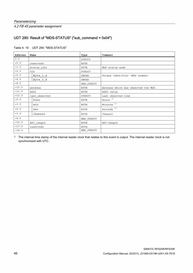
Parameterizing 4.2 FB 45 parameter assignment
SIMATIC RF620R/RF630R 46 Configuration Manual, 02/2013, J31069-D0196-U001-A5-7618
UDT 290: Result of "MDS-STATUS" ("sub_command = 0x04")
Table 4- 19 UDT 290: "MDS-STATUS"
Address Name Type Comment 0.0 STRUCT +0.0 reserved0 BYTE +1.0 status_info BYTE MDS status mode +2.0 UID STRUCT +0.0 Byte_1_4 DWORD +4.0 Byte_5_8 DWORD
Unique identifier (MDS number)
=8.0 END_STRUCT +10.0 antenna BYTE Antenna which has observed the MDS +11.0 RSSI BYTE RSSI value +12.0 last_observed STRUCT Last observed time +0.0 hour BYTE Hours 1)
+1.0 min BYTE Minutes 1)
+2.0 sec BYTE Seconds 1)
+3.0 channel BYTE Channel
=4.0 END_STRUCT +16.0 EPC_length BYTE EPC-Length +17.0 reserved1 BYTE =18.0 END_STRUCT
1) The internal time stamp of the internal reader clock that relates to this event is output. The internal reader clock is not synchronized with UTC.
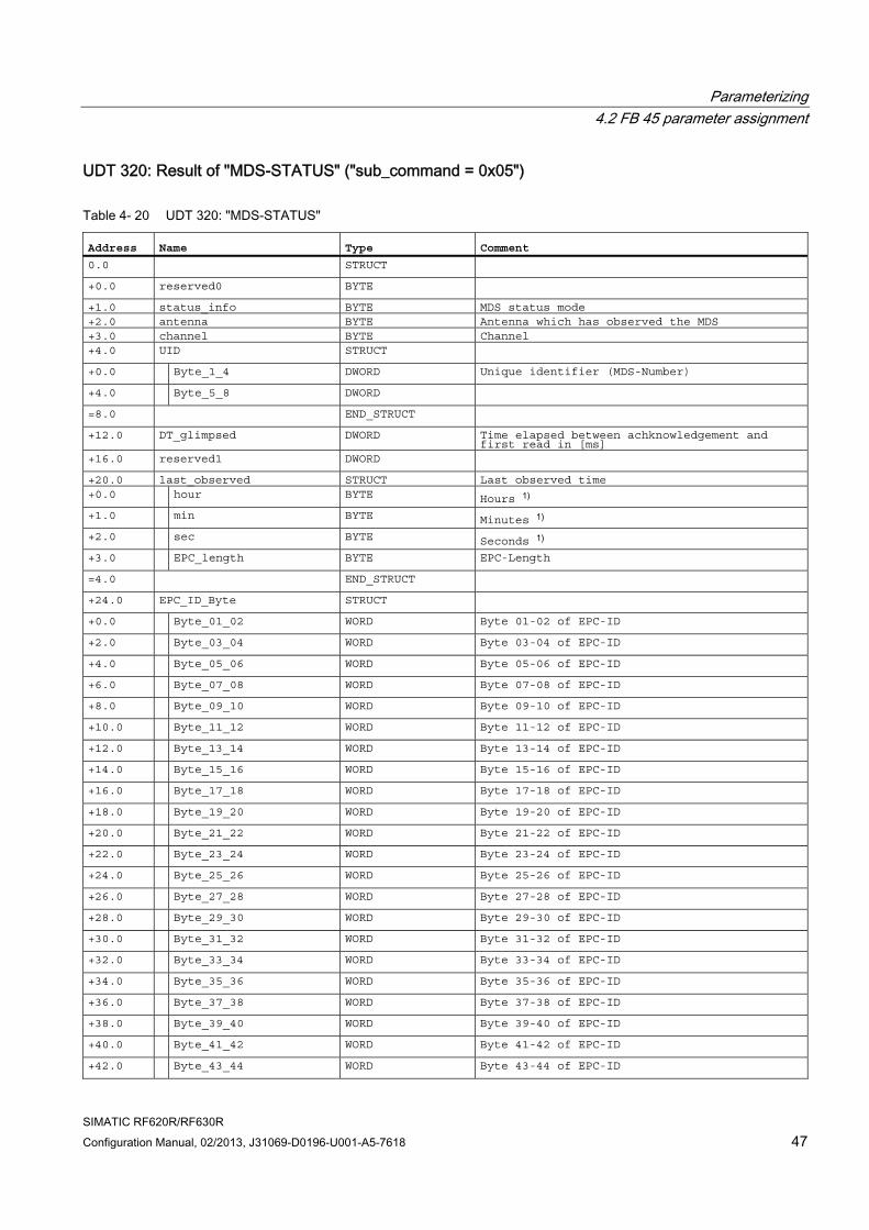
Parameterizing 4.2 FB 45 parameter assignment
SIMATIC RF620R/RF630R Configuration Manual, 02/2013, J31069-D0196-U001-A5-7618 47
UDT 320: Result of "MDS-STATUS" ("sub_command = 0x05")
Table 4- 20 UDT 320: "MDS-STATUS"
Address Name Type Comment 0.0 STRUCT +0.0 reserved0 BYTE +1.0 status_info BYTE MDS status mode +2.0 antenna BYTE Antenna which has observed the MDS +3.0 channel BYTE Channel +4.0 UID STRUCT +0.0 Byte_1_4 DWORD Unique identifier (MDS-Number) +4.0 Byte_5_8 DWORD =8.0 END_STRUCT +12.0 DT_glimpsed DWORD Time elapsed between achknowledgement and
first read in [ms] +16.0 reserved1 DWORD +20.0 last_observed STRUCT Last observed time +0.0 hour BYTE Hours 1) +1.0 min BYTE Minutes 1) +2.0 sec BYTE Seconds 1) +3.0 EPC_length BYTE EPC-Length =4.0 END_STRUCT +24.0 EPC_ID_Byte STRUCT +0.0 Byte_01_02 WORD Byte 01-02 of EPC-ID +2.0 Byte_03_04 WORD Byte 03-04 of EPC-ID +4.0 Byte_05_06 WORD Byte 05-06 of EPC-ID +6.0 Byte_07_08 WORD Byte 07-08 of EPC-ID +8.0 Byte_09_10 WORD Byte 09-10 of EPC-ID +10.0 Byte_11_12 WORD Byte 11-12 of EPC-ID +12.0 Byte_13_14 WORD Byte 13-14 of EPC-ID +14.0 Byte_15_16 WORD Byte 15-16 of EPC-ID +16.0 Byte_17_18 WORD Byte 17-18 of EPC-ID +18.0 Byte_19_20 WORD Byte 19-20 of EPC-ID +20.0 Byte_21_22 WORD Byte 21-22 of EPC-ID +22.0 Byte_23_24 WORD Byte 23-24 of EPC-ID +24.0 Byte_25_26 WORD Byte 25-26 of EPC-ID +26.0 Byte_27_28 WORD Byte 27-28 of EPC-ID +28.0 Byte_29_30 WORD Byte 29-30 of EPC-ID +30.0 Byte_31_32 WORD Byte 31-32 of EPC-ID +32.0 Byte_33_34 WORD Byte 33-34 of EPC-ID +34.0 Byte_35_36 WORD Byte 35-36 of EPC-ID +36.0 Byte_37_38 WORD Byte 37-38 of EPC-ID +38.0 Byte_39_40 WORD Byte 39-40 of EPC-ID +40.0 Byte_41_42 WORD Byte 41-42 of EPC-ID +42.0 Byte_43_44 WORD Byte 43-44 of EPC-ID
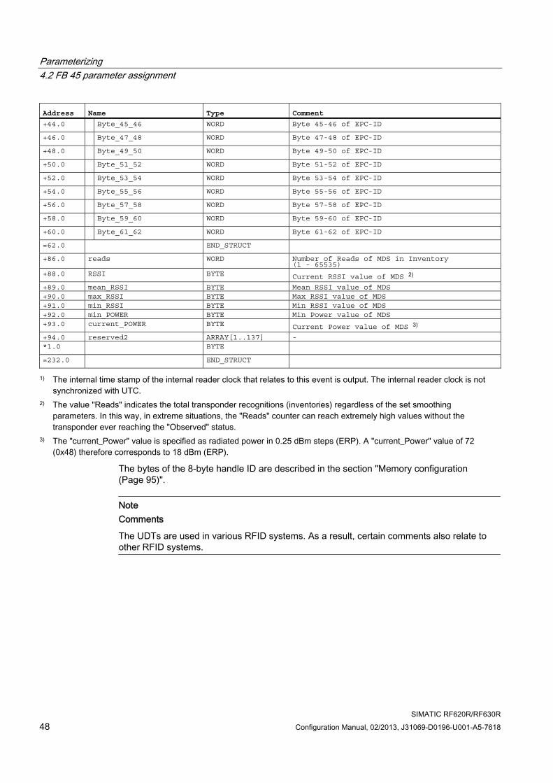
Parameterizing 4.2 FB 45 parameter assignment
SIMATIC RF620R/RF630R 48 Configuration Manual, 02/2013, J31069-D0196-U001-A5-7618
Address Name Type Comment +44.0 Byte_45_46 WORD Byte 45-46 of EPC-ID +46.0 Byte_47_48 WORD Byte 47-48 of EPC-ID +48.0 Byte_49_50 WORD Byte 49-50 of EPC-ID +50.0 Byte_51_52 WORD Byte 51-52 of EPC-ID +52.0 Byte_53_54 WORD Byte 53-54 of EPC-ID +54.0 Byte_55_56 WORD Byte 55-56 of EPC-ID +56.0 Byte_57_58 WORD Byte 57-58 of EPC-ID +58.0 Byte_59_60 WORD Byte 59-60 of EPC-ID +60.0 Byte_61_62 WORD Byte 61-62 of EPC-ID =62.0 END_STRUCT +86.0 reads WORD Number of Reads of MDS in Inventory
(1 - 65535) +88.0 RSSI BYTE Current RSSI value of MDS 2) +89.0 mean_RSSI BYTE Mean RSSI value of MDS +90.0 max_RSSI BYTE Max RSSI value of MDS +91.0 min_RSSI BYTE Min RSSI value of MDS +92.0 min_POWER BYTE Min Power value of MDS +93.0 current_POWER BYTE Current Power value of MDS 3) +94.0 reserved2 ARRAY[1..137] - *1.0 BYTE =232.0 END_STRUCT
1) The internal time stamp of the internal reader clock that relates to this event is output. The internal reader clock is not synchronized with UTC.
2) The value "Reads" indicates the total transponder recognitions (inventories) regardless of the set smoothing parameters. In this way, in extreme situations, the "Reads" counter can reach extremely high values without the transponder ever reaching the "Observed" status.
3) The "current_Power" value is specified as radiated power in 0.25 dBm steps (ERP). A "current_Power" value of 72 (0x48) therefore corresponds to 18 dBm (ERP).
The bytes of the 8-byte handle ID are described in the section "Memory configuration (Page 95)".
Note Comments
The UDTs are used in various RFID systems. As a result, certain comments also relate to other RFID systems.
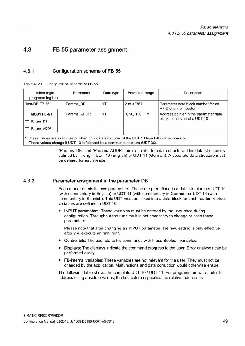
Parameterizing 4.3 FB 55 parameter assignment
SIMATIC RF620R/RF630R Configuration Manual, 02/2013, J31069-D0196-U001-A5-7618 49
4.3 FB 55 parameter assignment
4.3.1 Configuration scheme of FB 55
Table 4- 21 Configuration scheme of FB 55
Ladder logic programming box
Parameter Data type Permitted range Description
"Inst-DB FB 55"
MOBY FB-MT
Params_DB
Params_ADDR
Params_DB Params_ADDR
INT INT
2 to 32767 0, 50, 100,... *)
Parameter data block number for an RFID channel (reader) Address pointer in the parameter data block to the start of a UDT 10
*) These values are examples of when only data structures of the UDT 10 type follow in succession. These values change if UDT 10 is followed by a command structure (UDT 30).
"Params_DB" and "Params_ADDR" form a pointer to a data structure. This data structure is defined by linking in UDT 10 (English) or UDT 11 (German). A separate data structure must be defined for each reader.
4.3.2 Parameter assignment in the parameter DB Each reader needs its own parameters. These are predefined in a data structure as UDT 10 (with commentary in English) or UDT 11 (with commentary in German) or UDT 14 (with commentary in Spanish). This UDT must be linked into a data block for each reader. Various variables are defined in UDT 10:
● INPUT parameters: These variables must be entered by the user once during configuration. Throughout the run time it is not necessary to change or scan these parameters.
Please note that after changing an INPUT parameter, the new setting is only effective after you execute an "init_run".
● Control bits: The user starts his commands with these Boolean variables.
● Displays: The displays indicate the command progress to the user. Error analyses can be performed easily.
● FB-internal variables: These variables are not relevant for the user. They must not be changed by the application. Malfunctions and data corruption would otherwise ensue.
The following table shows the complete UDT 10 / UDT 11. For programmers who prefer to address using absolute values, the first column specifies the relative addresses.
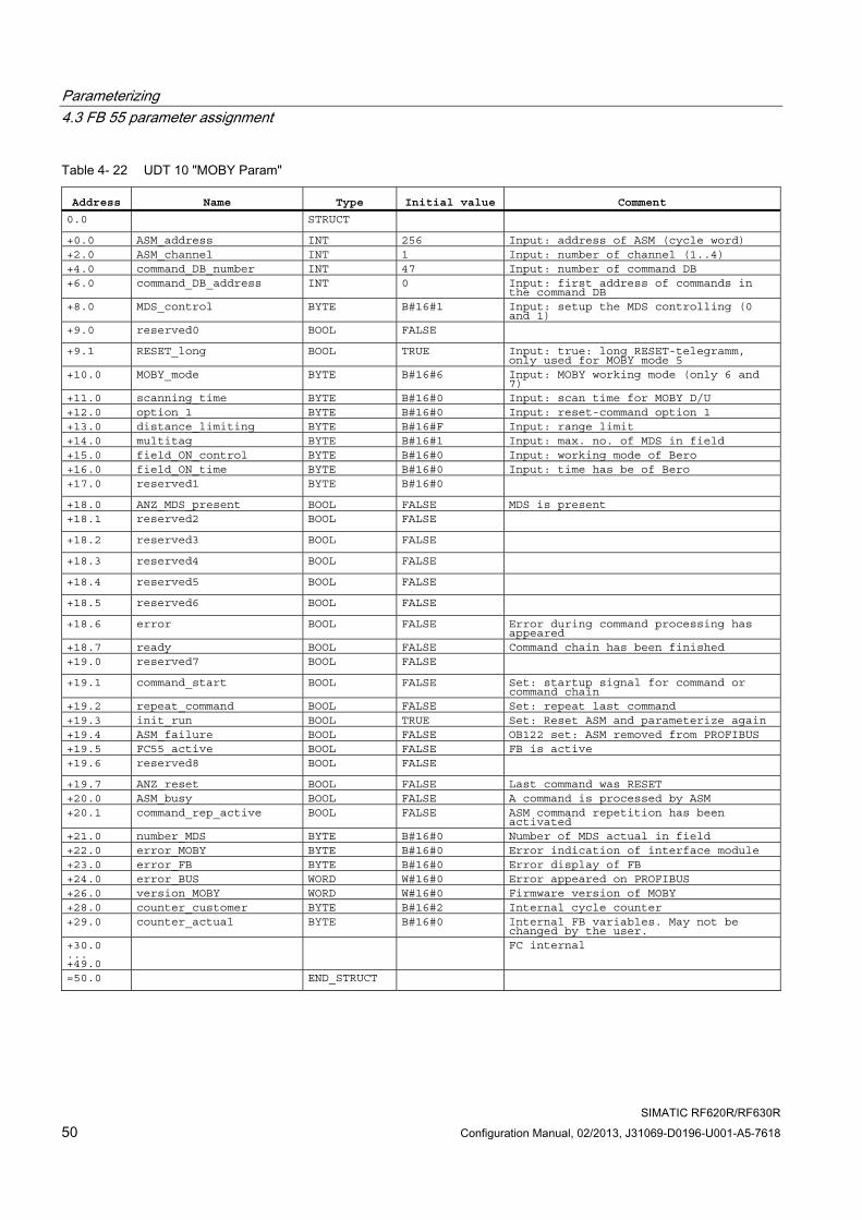
Parameterizing 4.3 FB 55 parameter assignment
SIMATIC RF620R/RF630R 50 Configuration Manual, 02/2013, J31069-D0196-U001-A5-7618
Table 4- 22 UDT 10 "MOBY Param"
Address Name Type Initial value Comment 0.0 STRUCT +0.0 ASM_address INT 256 Input: address of ASM (cycle word) +2.0 ASM_channel INT 1 Input: number of channel (1..4) +4.0 command_DB_number INT 47 Input: number of command DB +6.0 command_DB_address INT 0 Input: first address of commands in
the command DB +8.0 MDS_control BYTE B#16#1 Input: setup the MDS controlling (0
and 1) +9.0 reserved0 BOOL FALSE +9.1 RESET_long BOOL TRUE Input: true: long RESET-telegramm,
only used for MOBY mode 5 +10.0 MOBY_mode BYTE B#16#6 Input: MOBY working mode (only 6 and
7) +11.0 scanning_time BYTE B#16#0 Input: scan time for MOBY D/U +12.0 option_1 BYTE B#16#0 Input: reset-command option 1 +13.0 distance_limiting BYTE B#16#F Input: range limit +14.0 multitag BYTE B#16#1 Input: max. no. of MDS in field +15.0 field_ON_control BYTE B#16#0 Input: working mode of Bero +16.0 field_ON_time BYTE B#16#0 Input: time has be of Bero +17.0 reserved1 BYTE B#16#0 +18.0 ANZ_MDS_present BOOL FALSE MDS is present +18.1 reserved2 BOOL FALSE +18.2 reserved3 BOOL FALSE +18.3 reserved4 BOOL FALSE +18.4 reserved5 BOOL FALSE +18.5 reserved6 BOOL FALSE +18.6 error BOOL FALSE Error during command processing has
appeared +18.7 ready BOOL FALSE Command chain has been finished +19.0 reserved7 BOOL FALSE +19.1 command_start BOOL FALSE Set: startup signal for command or
command chain +19.2 repeat_command BOOL FALSE Set: repeat last command +19.3 init_run BOOL TRUE Set: Reset ASM and parameterize again +19.4 ASM_failure BOOL FALSE OB122 set: ASM removed from PROFIBUS +19.5 FC55_active BOOL FALSE FB is active +19.6 reserved8 BOOL FALSE +19.7 ANZ_reset BOOL FALSE Last command was RESET +20.0 ASM_busy BOOL FALSE A command is processed by ASM +20.1 command_rep_active BOOL FALSE ASM command repetition has been
activated +21.0 number_MDS BYTE B#16#0 Number of MDS actual in field +22.0 error_MOBY BYTE B#16#0 Error indication of interface module +23.0 error_FB BYTE B#16#0 Error display of FB +24.0 error_BUS WORD W#16#0 Error appeared on PROFIBUS +26.0 version_MOBY WORD W#16#0 Firmware version of MOBY +28.0 counter_customer BYTE B#16#2 Internal cycle counter +29.0 counter_actual BYTE B#16#0 Internal FB variables. May not be
changed by the user. +30.0 ... +49.0
FC internal
=50.0 END_STRUCT
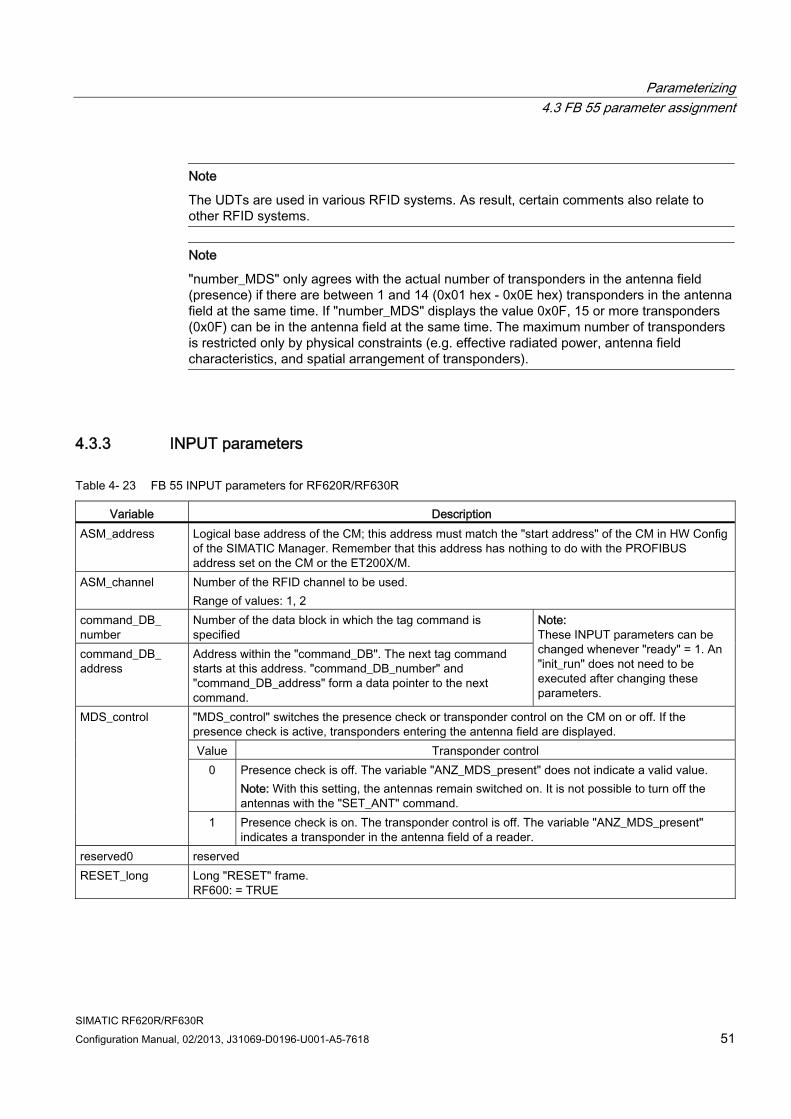
Parameterizing 4.3 FB 55 parameter assignment
SIMATIC RF620R/RF630R Configuration Manual, 02/2013, J31069-D0196-U001-A5-7618 51
Note
The UDTs are used in various RFID systems. As result, certain comments also relate to other RFID systems.
Note
"number_MDS" only agrees with the actual number of transponders in the antenna field (presence) if there are between 1 and 14 (0x01 hex - 0x0E hex) transponders in the antenna field at the same time. If "number_MDS" displays the value 0x0F, 15 or more transponders (0x0F) can be in the antenna field at the same time. The maximum number of transponders is restricted only by physical constraints (e.g. effective radiated power, antenna field characteristics, and spatial arrangement of transponders).
4.3.3 INPUT parameters
Table 4- 23 FB 55 INPUT parameters for RF620R/RF630R
Variable Description ASM_address Logical base address of the CM; this address must match the "start address" of the CM in HW Config
of the SIMATIC Manager. Remember that this address has nothing to do with the PROFIBUS address set on the CM or the ET200X/M.
ASM_channel Number of the RFID channel to be used. Range of values: 1, 2
command_DB_ number
Number of the data block in which the tag command is specified
command_DB_ address
Address within the "command_DB". The next tag command starts at this address. "command_DB_number" and "command_DB_address" form a data pointer to the next command.
Note: These INPUT parameters can be changed whenever "ready" = 1. An "init_run" does not need to be executed after changing these parameters.
"MDS_control" switches the presence check or transponder control on the CM on or off. If the presence check is active, transponders entering the antenna field are displayed. Value Transponder control
0 Presence check is off. The variable "ANZ_MDS_present" does not indicate a valid value. Note: With this setting, the antennas remain switched on. It is not possible to turn off the antennas with the "SET_ANT" command.
MDS_control
1 Presence check is on. The transponder control is off. The variable "ANZ_MDS_present" indicates a transponder in the antenna field of a reader.
reserved0 reserved RESET_long Long "RESET" frame.
RF600: = TRUE
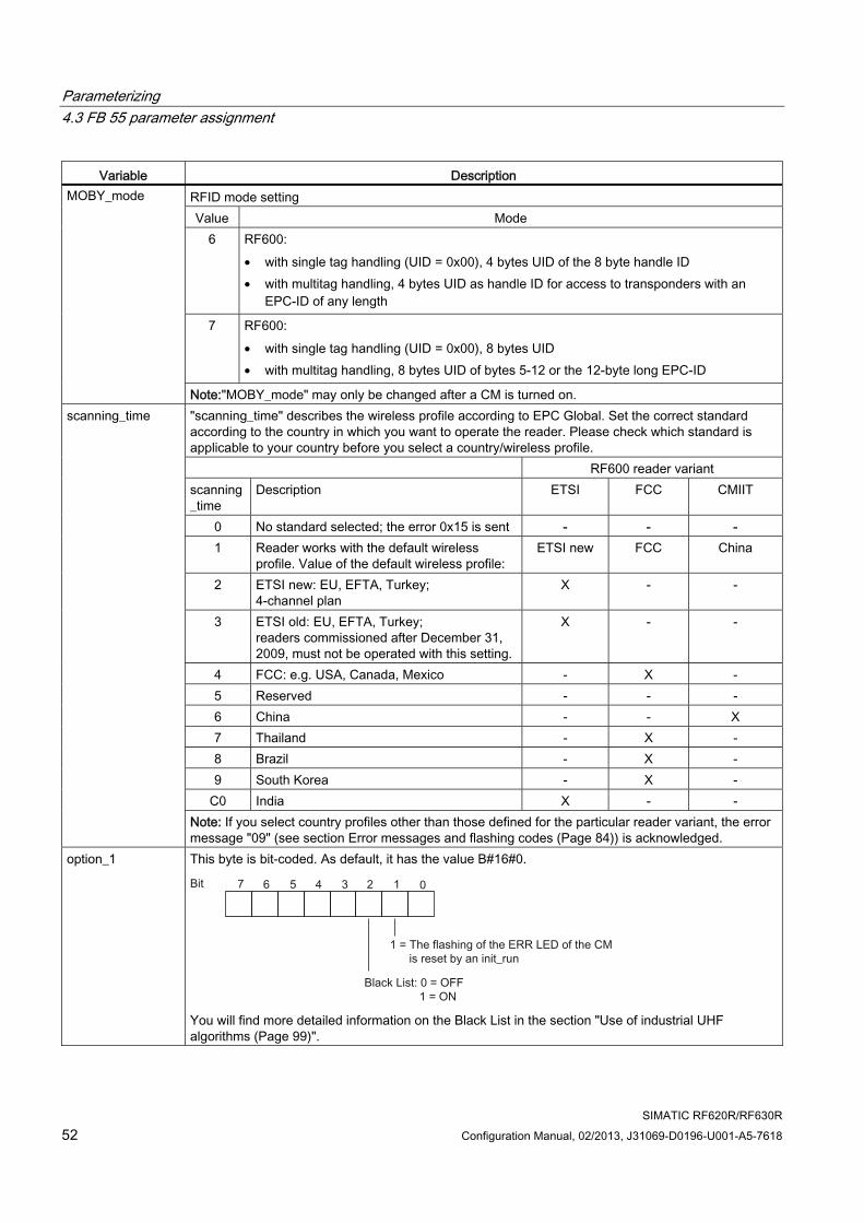
Parameterizing 4.3 FB 55 parameter assignment
SIMATIC RF620R/RF630R 52 Configuration Manual, 02/2013, J31069-D0196-U001-A5-7618
Variable Description RFID mode setting Value Mode
6 RF600: • with single tag handling (UID = 0x00), 4 bytes UID of the 8 byte handle ID • with multitag handling, 4 bytes UID as handle ID for access to transponders with an
EPC-ID of any length
7 RF600: • with single tag handling (UID = 0x00), 8 bytes UID • with multitag handling, 8 bytes UID of bytes 5-12 or the 12-byte long EPC-ID
MOBY_mode
Note:"MOBY_mode" may only be changed after a CM is turned on. "scanning_time" describes the wireless profile according to EPC Global. Set the correct standard according to the country in which you want to operate the reader. Please check which standard is applicable to your country before you select a country/wireless profile. RF600 reader variant scanning_time
Description ETSI FCC CMIIT
0 No standard selected; the error 0x15 is sent - - - 1 Reader works with the default wireless
profile. Value of the default wireless profile: ETSI new FCC China
2 ETSI new: EU, EFTA, Turkey; 4-channel plan
X - -
3 ETSI old: EU, EFTA, Turkey; readers commissioned after December 31, 2009, must not be operated with this setting.
X - -
4 FCC: e.g. USA, Canada, Mexico - X - 5 Reserved - - - 6 China - - X 7 Thailand - X - 8 Brazil - X - 9 South Korea - X -
C0 India X - -
scanning_time
Note: If you select country profiles other than those defined for the particular reader variant, the error message "09" (see section Error messages and flashing codes (Page 84)) is acknowledged.
option_1 This byte is bit-coded. As default, it has the value B#16#0.
You will find more detailed information on the Black List in the section "Use of industrial UHF algorithms (Page 99)".
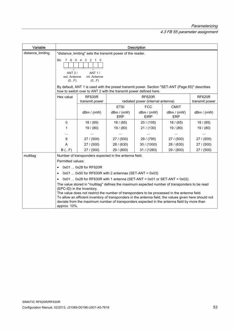
Parameterizing 4.3 FB 55 parameter assignment
SIMATIC RF620R/RF630R Configuration Manual, 02/2013, J31069-D0196-U001-A5-7618 53
Variable Description "distance_limiting" sets the transmit power of the reader.
By default, ANT 1 is used with the preset transmit power. Section "SET-ANT (Page 65)" describes how to switch over to ANT 2 with the transmit power defined here.
RF630R transmit power
RF620R radiated power (internal antenna)
RF620R transmit power
Hex value
dBm / (mW)
ETSI dBm / (mW)
ERP
FCC dBm / (mW)
EIRP
CMIIT dBm / (mW)
ERP
dBm / (mW)
distance_limiting
0 1 ... 9 A
B (...F)
18 / (65) 19 / (80)
... 27 / (500) 27 / (500) 27 / (500)
18 / (65) 19 / (80)
... 27 / (500) 28 / (630) 29 / (800)
20 / (105) 21 / (130)
... 29 / (795) 30 / (1000) 31 / (1260)
18 / (65) 19 / (80)
... 27 / (500) 28 / (630) 29 / (800)
18 / (65) 19 / (80)
... 27 / (500) 27 / (500) 27 / (500)
multitag Number of transponders expected in the antenna field. Permitted values: • 0x01 ... 0x28 for RF620R • 0x01 ... 0x50 for RF630R with 2 antennas (SET-ANT = 0x03) • 0x01 ... 0x28 for RF630R with 1 antenna (SET-ANT = 0x01 or SET-ANT = 0x02). The value stored in "multitag" defines the maximum expected number of transponders to be read (EPC-ID) in the Inventory. The value does not restrict the number of transponders to be processed in the antenna field. To allow an efficient inventory of transponders in the antenna field, the values given here should not deviate from the maximum number of transponders expected in the antenna field by more than approx. 10%.
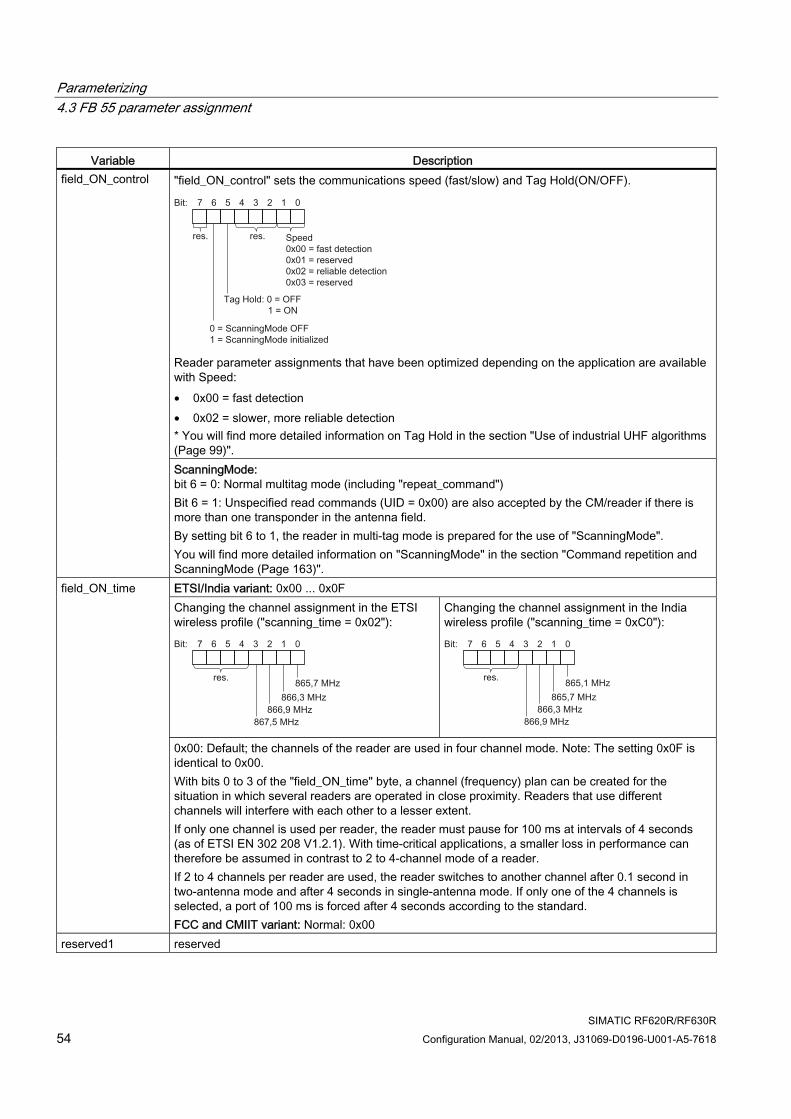
Parameterizing 4.3 FB 55 parameter assignment
SIMATIC RF620R/RF630R 54 Configuration Manual, 02/2013, J31069-D0196-U001-A5-7618
Variable Description "field_ON_control" sets the communications speed (fast/slow) and Tag Hold(ON/OFF).
Reader parameter assignments that have been optimized depending on the application are available with Speed: • 0x00 = fast detection • 0x02 = slower, more reliable detection * You will find more detailed information on Tag Hold in the section "Use of industrial UHF algorithms (Page 99)".
field_ON_control
ScanningMode: bit 6 = 0: Normal multitag mode (including "repeat_command") Bit 6 = 1: Unspecified read commands (UID = 0x00) are also accepted by the CM/reader if there is more than one transponder in the antenna field. By setting bit 6 to 1, the reader in multi-tag mode is prepared for the use of "ScanningMode". You will find more detailed information on "ScanningMode" in the section "Command repetition and ScanningMode (Page 163)". ETSI/India variant: 0x00 ... 0x0F Changing the channel assignment in the ETSI wireless profile ("scanning_time = 0x02"):
Changing the channel assignment in the India wireless profile ("scanning_time = 0xC0"):
field_ON_time
0x00: Default; the channels of the reader are used in four channel mode. Note: The setting 0x0F is identical to 0x00. With bits 0 to 3 of the "field_ON_time" byte, a channel (frequency) plan can be created for the situation in which several readers are operated in close proximity. Readers that use different channels will interfere with each other to a lesser extent. If only one channel is used per reader, the reader must pause for 100 ms at intervals of 4 seconds (as of ETSI EN 302 208 V1.2.1). With time-critical applications, a smaller loss in performance can therefore be assumed in contrast to 2 to 4-channel mode of a reader. If 2 to 4 channels per reader are used, the reader switches to another channel after 0.1 second in two-antenna mode and after 4 seconds in single-antenna mode. If only one of the 4 channels is selected, a port of 100 ms is forced after 4 seconds according to the standard. FCC and CMIIT variant: Normal: 0x00
reserved1 reserved
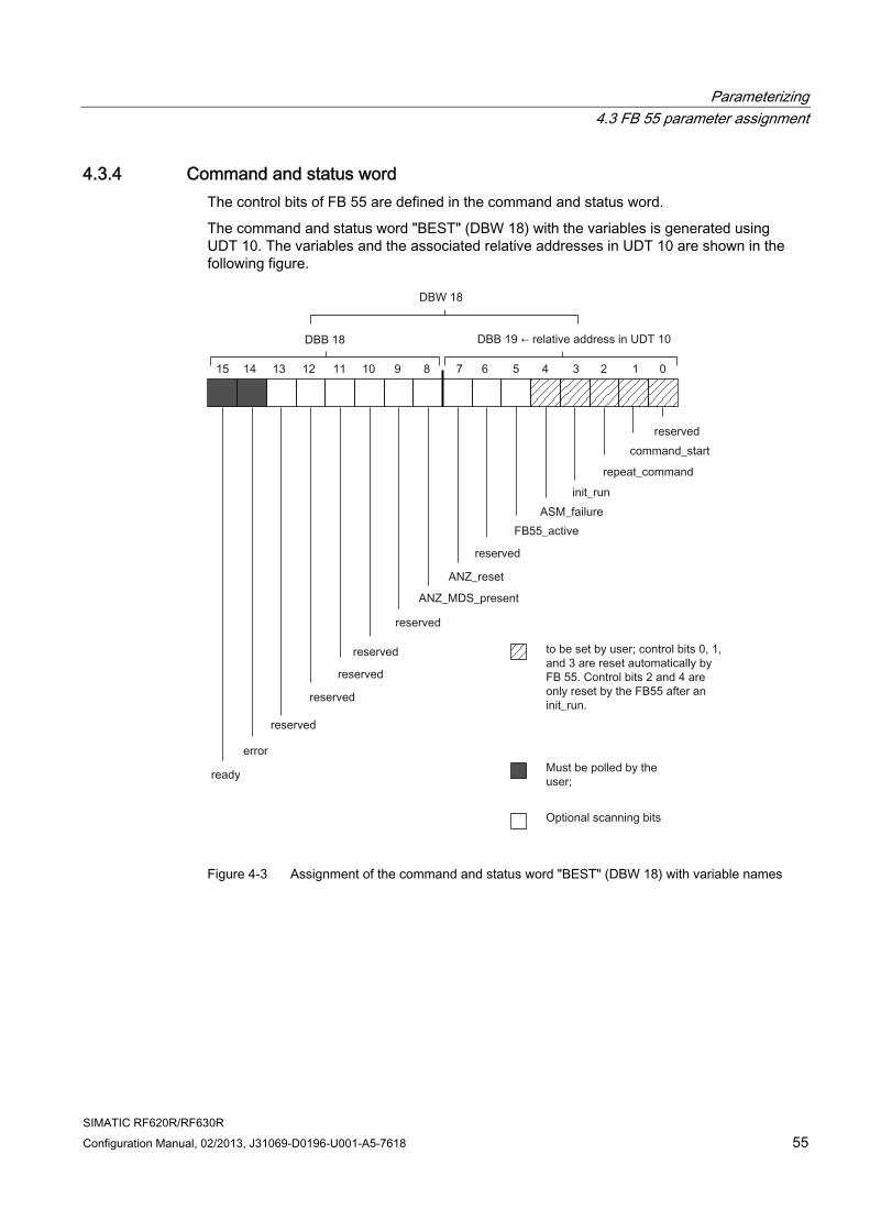
Parameterizing 4.3 FB 55 parameter assignment
SIMATIC RF620R/RF630R Configuration Manual, 02/2013, J31069-D0196-U001-A5-7618 55
4.3.4 Command and status word The control bits of FB 55 are defined in the command and status word.
The command and status word "BEST" (DBW 18) with the variables is generated using UDT 10. The variables and the associated relative addresses in UDT 10 are shown in the following figure.
Figure 4-3 Assignment of the command and status word "BEST" (DBW 18) with variable names
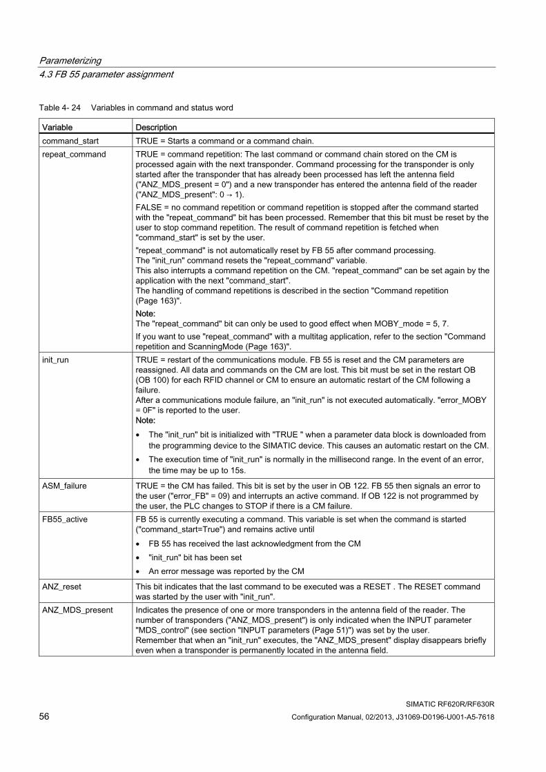
Parameterizing 4.3 FB 55 parameter assignment
SIMATIC RF620R/RF630R 56 Configuration Manual, 02/2013, J31069-D0196-U001-A5-7618
Table 4- 24 Variables in command and status word
Variable Description command_start TRUE = Starts a command or a command chain. repeat_command TRUE = command repetition: The last command or command chain stored on the CM is
processed again with the next transponder. Command processing for the transponder is only started after the transponder that has already been processed has left the antenna field ("ANZ_MDS_present = 0") and a new transponder has entered the antenna field of the reader ("ANZ_MDS_present": 0 → 1). FALSE = no command repetition or command repetition is stopped after the command started with the "repeat_command" bit has been processed. Remember that this bit must be reset by the user to stop command repetition. The result of command repetition is fetched when "command_start" is set by the user. "repeat_command" is not automatically reset by FB 55 after command processing. The "init_run" command resets the "repeat_command" variable. This also interrupts a command repetition on the CM. "repeat_command" can be set again by the application with the next "command_start". The handling of command repetitions is described in the section "Command repetition (Page 163)". Note: The "repeat_command" bit can only be used to good effect when MOBY_mode = 5, 7. If you want to use "repeat_command" with a multitag application, refer to the section "Command repetition and ScanningMode (Page 163)".
init_run TRUE = restart of the communications module. FB 55 is reset and the CM parameters are reassigned. All data and commands on the CM are lost. This bit must be set in the restart OB (OB 100) for each RFID channel or CM to ensure an automatic restart of the CM following a failure. After a communications module failure, an "init_run" is not executed automatically. "error_MOBY = 0F" is reported to the user. Note: • The "init_run" bit is initialized with "TRUE " when a parameter data block is downloaded from
the programming device to the SIMATIC device. This causes an automatic restart on the CM. • The execution time of "init_run" is normally in the millisecond range. In the event of an error,
the time may be up to 15s.
ASM_failure TRUE = the CM has failed. This bit is set by the user in OB 122. FB 55 then signals an error to the user ("error_FB" = 09) and interrupts an active command. If OB 122 is not programmed by the user, the PLC changes to STOP if there is a CM failure.
FB55_active FB 55 is currently executing a command. This variable is set when the command is started ("command_start=True") and remains active until • FB 55 has received the last acknowledgment from the CM • "init_run" bit has been set • An error message was reported by the CM
ANZ_reset This bit indicates that the last command to be executed was a RESET . The RESET command was started by the user with "init_run".
ANZ_MDS_present Indicates the presence of one or more transponders in the antenna field of the reader. The number of transponders ("ANZ_MDS_present") is only indicated when the INPUT parameter "MDS_control" (see section "INPUT parameters (Page 51)") was set by the user. Remember that when an "init_run" executes, the "ANZ_MDS_present" display disappears briefly even when a transponder is permanently located in the antenna field.
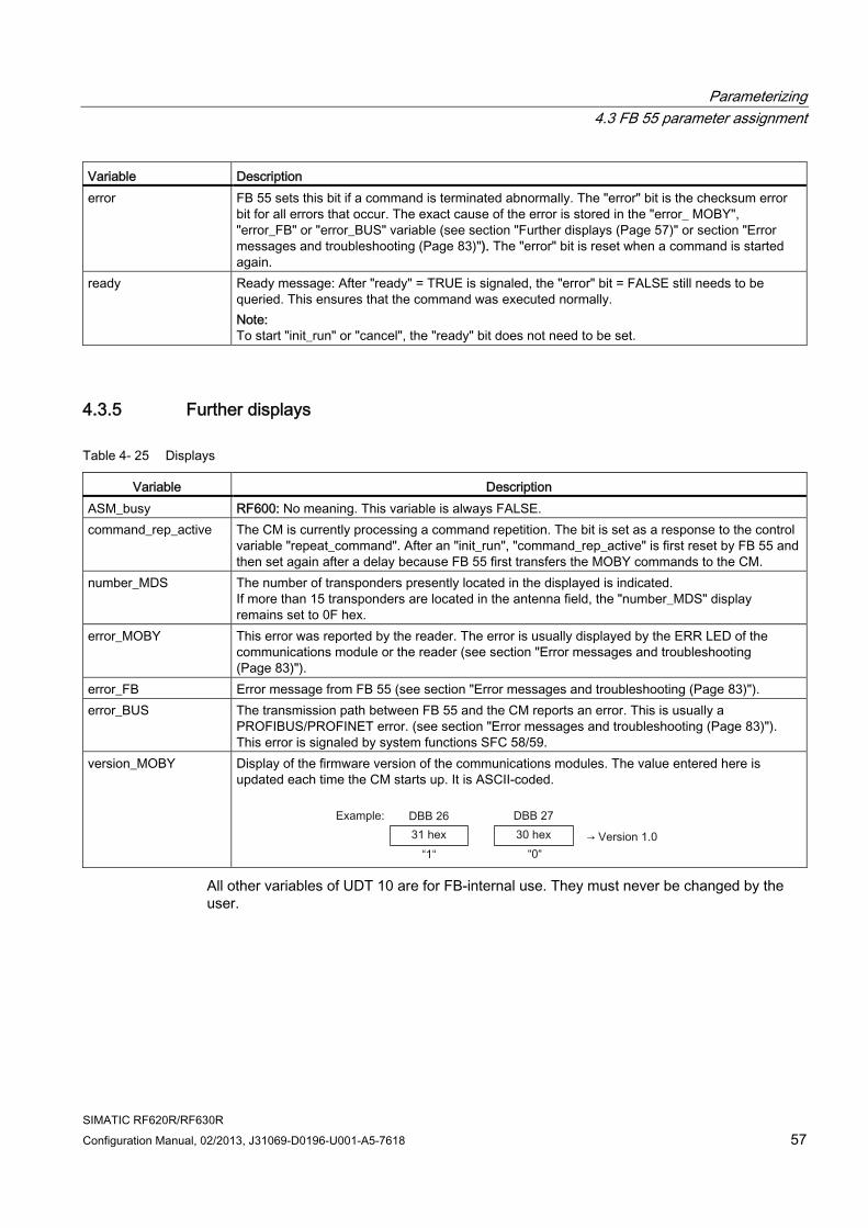
Parameterizing 4.3 FB 55 parameter assignment
SIMATIC RF620R/RF630R Configuration Manual, 02/2013, J31069-D0196-U001-A5-7618 57
Variable Description error FB 55 sets this bit if a command is terminated abnormally. The "error" bit is the checksum error
bit for all errors that occur. The exact cause of the error is stored in the "error_ MOBY", "error_FB" or "error_BUS" variable (see section "Further displays (Page 57)" or section "Error messages and troubleshooting (Page 83)"). The "error" bit is reset when a command is started again.
ready Ready message: After "ready" = TRUE is signaled, the "error" bit = FALSE still needs to be queried. This ensures that the command was executed normally. Note: To start "init_run" or "cancel", the "ready" bit does not need to be set.
4.3.5 Further displays
Table 4- 25 Displays
Variable Description ASM_busy RF600: No meaning. This variable is always FALSE. command_rep_active The CM is currently processing a command repetition. The bit is set as a response to the control
variable "repeat_command". After an "init_run", "command_rep_active" is first reset by FB 55 and then set again after a delay because FB 55 first transfers the MOBY commands to the CM.
number_MDS The number of transponders presently located in the displayed is indicated. If more than 15 transponders are located in the antenna field, the "number_MDS" display remains set to 0F hex.
error_MOBY This error was reported by the reader. The error is usually displayed by the ERR LED of the communications module or the reader (see section "Error messages and troubleshooting (Page 83)").
error_FB Error message from FB 55 (see section "Error messages and troubleshooting (Page 83)"). error_BUS The transmission path between FB 55 and the CM reports an error. This is usually a
PROFIBUS/PROFINET error. (see section "Error messages and troubleshooting (Page 83)"). This error is signaled by system functions SFC 58/59.
version_MOBY Display of the firmware version of the communications modules. The value entered here is updated each time the CM starts up. It is ASCII-coded.
All other variables of UDT 10 are for FB-internal use. They must never be changed by the user.
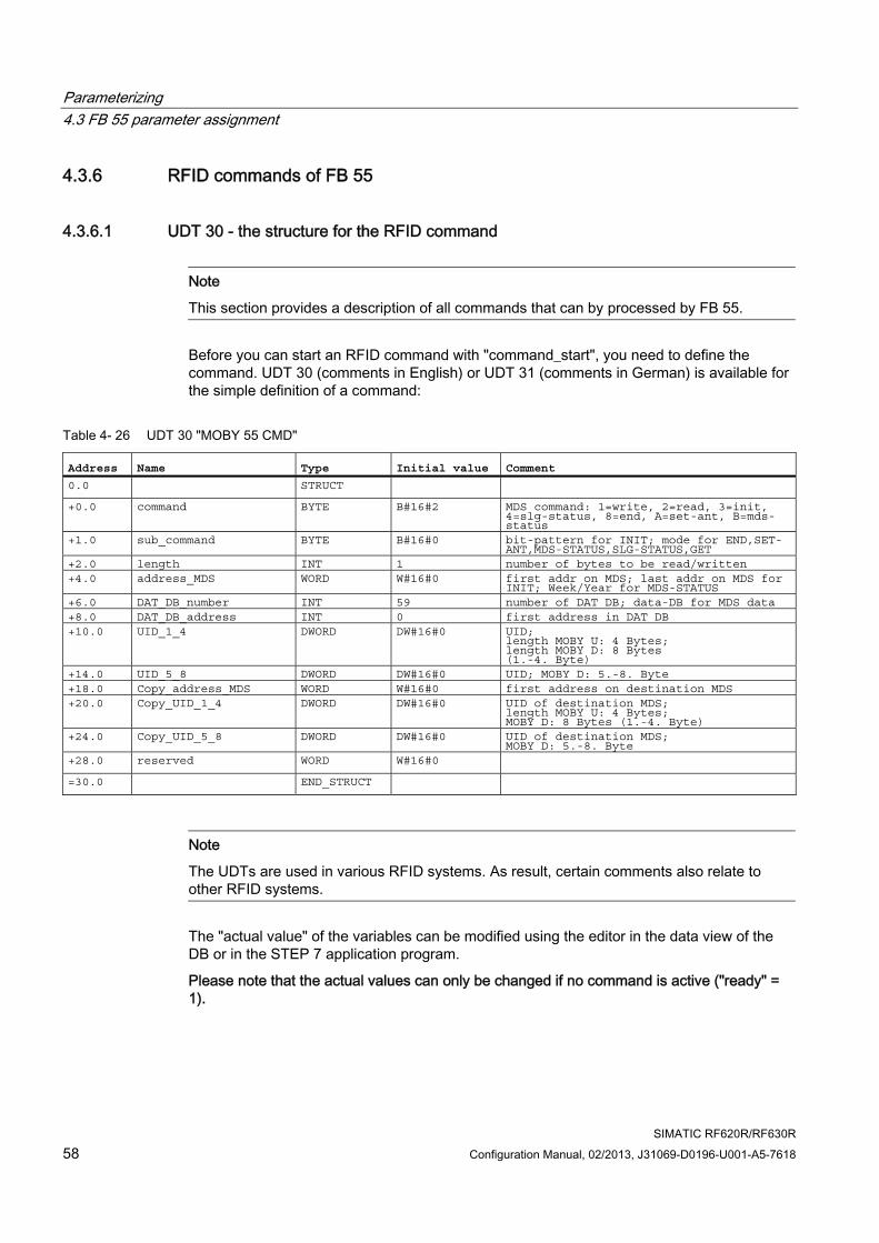
Parameterizing 4.3 FB 55 parameter assignment
SIMATIC RF620R/RF630R 58 Configuration Manual, 02/2013, J31069-D0196-U001-A5-7618
4.3.6 RFID commands of FB 55
4.3.6.1 UDT 30 - the structure for the RFID command
Note
This section provides a description of all commands that can by processed by FB 55.
Before you can start an RFID command with "command_start", you need to define the command. UDT 30 (comments in English) or UDT 31 (comments in German) is available for the simple definition of a command:
Table 4- 26 UDT 30 "MOBY 55 CMD"
Address Name Type Initial value Comment 0.0 STRUCT +0.0 command BYTE B#16#2 MDS command: 1=write, 2=read, 3=init,
4=slg-status, 8=end, A=set-ant, B=mds-status
+1.0 sub_command BYTE B#16#0 bit-pattern for INIT; mode for END,SET-ANT,MDS-STATUS,SLG-STATUS,GET
+2.0 length INT 1 number of bytes to be read/written +4.0 address_MDS WORD W#16#0 first addr on MDS; last addr on MDS for
INIT; Week/Year for MDS-STATUS +6.0 DAT_DB_number INT 59 number of DAT DB; data-DB for MDS data +8.0 DAT_DB_address INT 0 first address in DAT DB +10.0 UID_1_4 DWORD DW#16#0 UID;
length MOBY U: 4 Bytes; length MOBY D: 8 Bytes (1.-4. Byte)
+14.0 UID_5_8 DWORD DW#16#0 UID; MOBY D: 5.-8. Byte +18.0 Copy_address_MDS WORD W#16#0 first address on destination MDS +20.0 Copy_UID_1_4 DWORD DW#16#0 UID of destination MDS;
length MOBY U: 4 Bytes; MOBY D: 8 Bytes (1.-4. Byte)
+24.0 Copy_UID_5_8 DWORD DW#16#0 UID of destination MDS; MOBY D: 5.-8. Byte
+28.0 reserved WORD W#16#0 =30.0 END_STRUCT
Note
The UDTs are used in various RFID systems. As result, certain comments also relate to other RFID systems.
The "actual value" of the variables can be modified using the editor in the data view of the DB or in the STEP 7 application program.
Please note that the actual values can only be changed if no command is active ("ready" = 1).
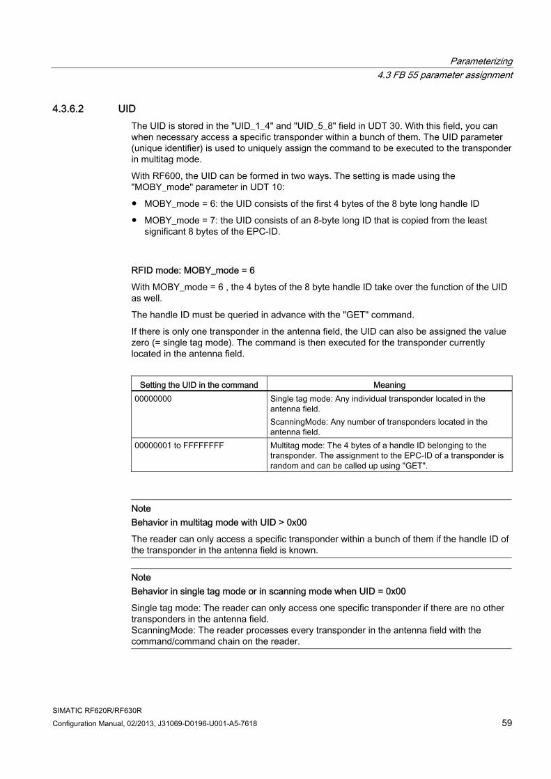
Parameterizing 4.3 FB 55 parameter assignment
SIMATIC RF620R/RF630R Configuration Manual, 02/2013, J31069-D0196-U001-A5-7618 59
4.3.6.2 UID The UID is stored in the "UID_1_4" and "UID_5_8" field in UDT 30. With this field, you can when necessary access a specific transponder within a bunch of them. The UID parameter (unique identifier) is used to uniquely assign the command to be executed to the transponder in multitag mode.
With RF600, the UID can be formed in two ways. The setting is made using the "MOBY_mode" parameter in UDT 10:
● MOBY_mode = 6: the UID consists of the first 4 bytes of the 8 byte long handle ID
● MOBY_mode = 7: the UID consists of an 8-byte long ID that is copied from the least significant 8 bytes of the EPC-ID.
RFID mode: MOBY_mode = 6
With MOBY_mode = 6 , the 4 bytes of the 8 byte handle ID take over the function of the UID as well.
The handle ID must be queried in advance with the "GET" command.
If there is only one transponder in the antenna field, the UID can also be assigned the value zero (= single tag mode). The command is then executed for the transponder currently located in the antenna field.
Setting the UID in the command Meaning
00000000 Single tag mode: Any individual transponder located in the antenna field. ScanningMode: Any number of transponders located in the antenna field.
00000001 to FFFFFFFF Multitag mode: The 4 bytes of a handle ID belonging to the transponder. The assignment to the EPC-ID of a transponder is random and can be called up using "GET".
Note Behavior in multitag mode with UID > 0x00
The reader can only access a specific transponder within a bunch of them if the handle ID of the transponder in the antenna field is known.
Note Behavior in single tag mode or in scanning mode when UID = 0x00
Single tag mode: The reader can only access one specific transponder if there are no other transponders in the antenna field. ScanningMode: The reader processes every transponder in the antenna field with the command/command chain on the reader.
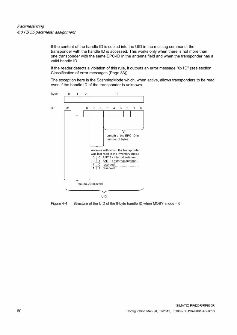
Parameterizing 4.3 FB 55 parameter assignment
SIMATIC RF620R/RF630R 60 Configuration Manual, 02/2013, J31069-D0196-U001-A5-7618
If the content of the handle ID is copied into the UID in the multitag command, the transponder with the handle ID is accessed. This works only when there is not more than one transponder with the same EPC-ID in the antenna field and when the transponder has a valid handle ID.
If the reader detects a violation of this rule, it outputs an error message "0x1D" (see section Classification of error messages (Page 83)).
The exception here is the ScanningMode which, when active, allows transponders to be read even if the handle ID of the transponder is unknown.
Figure 4-4 Structure of the UID of the 8-byte handle ID when MOBY_mode = 6
Parameterizing 4.3 FB 55 parameter assignment
SIMATIC RF620R/RF630R Configuration Manual, 02/2013, J31069-D0196-U001-A5-7618 61
RFID mode: MOBY_mode = 7
With MOBY_mode = 7 , the least significant part of the EPC-ID also takes over the function of the UID.
The EPC-ID must be queried in advance with the "GET" command.
If there is only one transponder in the antenna field, the UID can also be assigned the value zero. The command is then executed for the transponder currently located in the antenna field.
Setting the UID in the command Meaning
0000000000000000 Single tag mode: Any individual transponder located in the antenna field.
0000000000000001 to FFFFFFFFFFFFFFFF Multitag mode: The last 8 bytes of the EPC-ID are transferred in the UID field
Note
Note that the MSB bytes of the EPC-ID not used in the UID should always have the same content. If different values are used in the first bytes, an error message "0x1D" may be output when there is multitag access later to this transponder (UID ≠ to 00).
4.3.7 Parameter assignment of the commands with FB 55
4.3.7.1 Overview of commands
Table 4- 27 Overview of commands
Command [hex] Command normal chained syntax Description
01 41 WRITE 1) Write data to the transponder/reader 02 42 READ 1) Read data from the transponder/reader 03 43 INIT 1) Initialize transponder 04 44 SLG-STATUS Reader status 0A 4A SET-ANT Turn antenna on/off,
if necessary initialize UHF algorithms. 0B 4B MDS-STATUS MDS/transponder status 0C 4C GET 1) Display transponder and Black List
1) For information on the memory structure, refer to the sections "Memory configuration (Page 95)" and "Special memory configuration of the RF600 transponders (Page 98)".
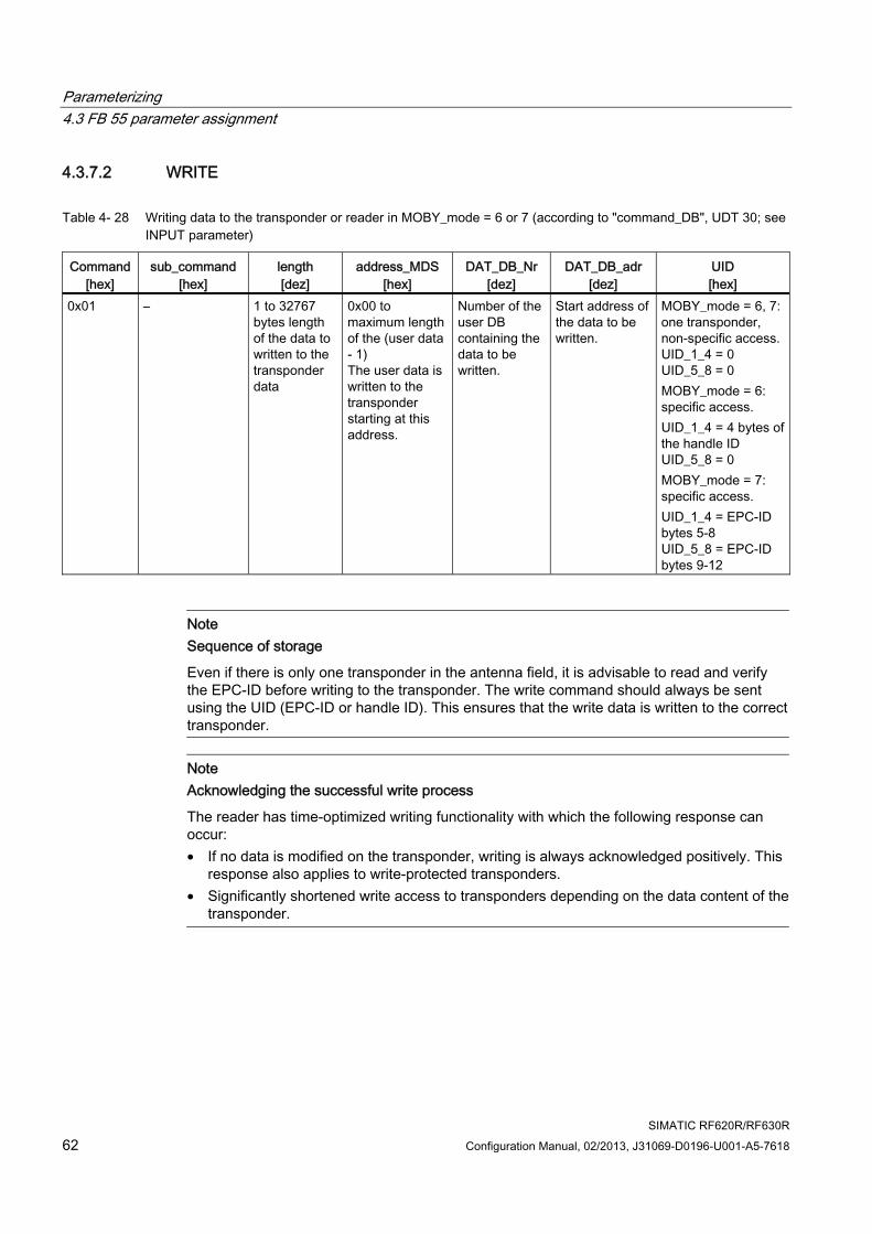
Parameterizing 4.3 FB 55 parameter assignment
SIMATIC RF620R/RF630R 62 Configuration Manual, 02/2013, J31069-D0196-U001-A5-7618
4.3.7.2 WRITE
Table 4- 28 Writing data to the transponder or reader in MOBY_mode = 6 or 7 (according to "command_DB", UDT 30; see INPUT parameter)
Command [hex]
sub_command [hex]
length [dez]
address_MDS [hex]
DAT_DB_Nr[dez]
DAT_DB_adr [dez]
UID [hex]
0x01 – 1 to 32767 bytes length of the data to written to the transponder data
0x00 to maximum length of the (user data - 1) The user data is written to the transponder starting at this address.
Number of the user DB containing the data to be written.
Start address of the data to be written.
MOBY_mode = 6, 7: one transponder, non-specific access.UID_1_4 = 0 UID_5_8 = 0 MOBY_mode = 6: specific access. UID_1_4 = 4 bytes of the handle ID UID_5_8 = 0 MOBY_mode = 7: specific access. UID_1_4 = EPC-ID bytes 5-8 UID_5_8 = EPC-ID bytes 9-12
Note Sequence of storage
Even if there is only one transponder in the antenna field, it is advisable to read and verify the EPC-ID before writing to the transponder. The write command should always be sent using the UID (EPC-ID or handle ID). This ensures that the write data is written to the correct transponder.
Note Acknowledging the successful write process
The reader has time-optimized writing functionality with which the following response can occur: • If no data is modified on the transponder, writing is always acknowledged positively. This
response also applies to write-protected transponders. • Significantly shortened write access to transponders depending on the data content of the
transponder.

Parameterizing 4.3 FB 55 parameter assignment
SIMATIC RF620R/RF630R Configuration Manual, 02/2013, J31069-D0196-U001-A5-7618 63
4.3.7.3 READ
Table 4- 29 Read data from the transponder/reader in MOBY_mode = 6 or 7 (according to "command_DB", UDT 30; see INPUT parameter)
Command [hex]
sub_command[hex]
length [dez]
address_MDS [hex]
DAT_DB_Nr[dez]
DAT_DB_adr [dez]
UID [hex]
0x02 – 1 to 32767 bytes - length of data to be read from the transponder
0x00 to maximum length of the (user data - 1) The user data is read from the transponder starting at this address.
Number of the user DB containing the read data.
Start address of the data that was read.
MOBY_mode = 6, 7: on transponder, non-specific access. UID_1_4 = 0 UID_5_8 = 0 MOBY_mode = 6: specific access. UID_1_4 = 4 bytes of the handle ID UID_5_8 = 0 MOBY_mode = 7: specific access. UID_1_4 = EPC-ID bytes 5-8 UID_5_8 = EPC-ID bytes 9-12
4.3.7.4 INIT
Table 4- 30 Initialize transponder in MOBY_mode = 6 or 7 (according to "command_DB", UDT 30; see INPUT parameter)
Command [hex]
sub_command[hex]
length [dez]
address_MDS [hex]
DAT_DB_Nr[dez]
DAT_DB_adr [dez]
UID [hex]
0x03 0x00 to 0xFF Value with which the transponder is written
– Memory size of transponder to be initialized. You will find the memory size in the technical specifications of the transponder.
- - MOBY_mode = 6, 7: on transponder, non-specific access. UID_1_4 = 0 UID_5_8 = 0 MOBY_mode = 6: specific access. UID_1_4 = 4 bytes of the handle ID UID_5_8 = 0 MOBY_mode = 7: specific access. UID_1_4 = EPC-ID bytes 5-8 UID_5_8 = EPC-ID bytes 9-12
This command is used to initialize the user-memory area. During initialization, data relating to the preset length is written to the transponder.

Parameterizing 4.3 FB 55 parameter assignment
SIMATIC RF620R/RF630R 64 Configuration Manual, 02/2013, J31069-D0196-U001-A5-7618
4.3.7.5 SLG STATUS
Table 4- 31 SLG-STATUS (according to "command_DB", UDT 30)
Command [hex]
sub_command [hex]
length [dez]
address_MDS[hex]
DAT_DB_Nr [dez]
DAT_DB_adr [dez]
UID [hex]
0x07 = status after UDT 300 1) 2)
Number of the user DB with UDT 30x structure in which the read data will be stored.
0x08 = status after UDT 340 1)
Number of the user DB with UDT 34x structure in which the read data will be stored.
0x20 = first entries from Black List 2)
0x04
0x21 = all other entries from Black List 2)
– –
Number of the user DB with UDT 37x structure in which the read data will be stored.
Start address of the data that was read.
UID_1_4 = 0 UID_5_8 = 0
1) You will find the UDT description in the section "UDTs of FB 55 (Page 71)". 2) The "SLG-STATUS" can also be queried with the "sub_command 0x20" and "0x21". This in this case, however, the use of the "GET" command is more suitable.
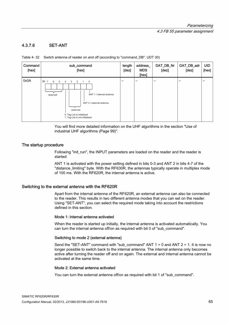
Parameterizing 4.3 FB 55 parameter assignment
SIMATIC RF620R/RF630R Configuration Manual, 02/2013, J31069-D0196-U001-A5-7618 65
4.3.7.6 SET-ANT
Table 4- 32 Switch antenna of reader on and off (according to "command_DB", UDT 30)
Command [hex]
sub_command [hex]
length[dez]
address_MDS [hex]
DAT_DB_Nr [dez]
DAT_DB_adr[dez]
UID[hex]
0x0A – – – – –
You will find more detailed information on the UHF algorithms in the section "Use of industrial UHF algorithms (Page 99)".
The startup procedure Following "init_run", the INPUT parameters are loaded on the reader and the reader is started:
ANT 1 is activated with the power setting defined in bits 0-3 and ANT 2 in bits 4-7 of the "distance_limiting" byte. With the RF630R, the antennas typically operate in multiplex mode of 100 ms. With the RF620R, the internal antenna is active.
Switching to the external antenna with the RF620R Apart from the internal antenna of the RF620R, an external antenna can also be connected to the reader. This results in two different antenna modes that you can set on the reader. Using "SET-ANT", you can select the required mode taking into account the restrictions defined in this section.
Mode 1: Internal antenna activated
When the reader is started up initially, the internal antenna is activated automatically. You can turn the internal antenna off/on as required with bit 0 of "sub_command".
Switching to mode 2 (external antenna)
Send the "SET-ANT" command with "sub_command" ANT 1 = 0 and ANT 2 = 1. It is now no longer possible to switch back to the internal antenna. The internal antenna only becomes active after turning the reader off and on again. The external and internal antenna cannot be activated at the same time.
Mode 2: External antenna activated
You can turn the external antenna off/on as required with bit 1 of "sub_command".
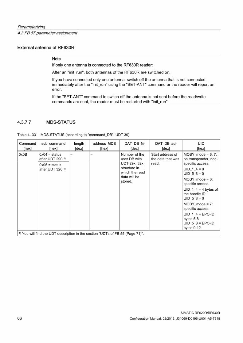
Parameterizing 4.3 FB 55 parameter assignment
SIMATIC RF620R/RF630R 66 Configuration Manual, 02/2013, J31069-D0196-U001-A5-7618
External antenna of RF630R
Note If only one antenna is connected to the RF630R reader:
After an "init_run", both antennas of the RF630R are switched on.
If you have connected only one antenna, switch off the antenna that is not connected immediately after the "init_run" using the "SET-ANT" command or the reader will report an error.
If the "SET-ANT" command to switch off the antenna is not sent before the read/write commands are sent, the reader must be restarted with "init_run".
4.3.7.7 MDS-STATUS
Table 4- 33 MDS-STATUS (according to "command_DB", UDT 30)
Command [hex]
sub_command [hex]
length [dez]
address_MDS[hex]
DAT_DB_Nr [dez]
DAT_DB_adr [dez]
UID [hex]
0x04 = status after UDT 290 1)
0x0B
0x05 = status after UDT 320 1)
– – Number of the user DB with UDT 29x, 32x structure in which the read data will be stored.
Start address of the data that was read.
MOBY_mode = 6, 7: on transponder, non-specific access. UID_1_4 = 0 UID_5_8 = 0 MOBY_mode = 6: specific access. UID_1_4 = 4 bytes of the handle ID UID_5_8 = 0 MOBY_mode = 7: specific access. UID_1_4 = EPC-ID bytes 5-8 UID_5_8 = EPC-ID bytes 9-12
1) You will find the UDT description in the section "UDTs of FB 55 (Page 71)".
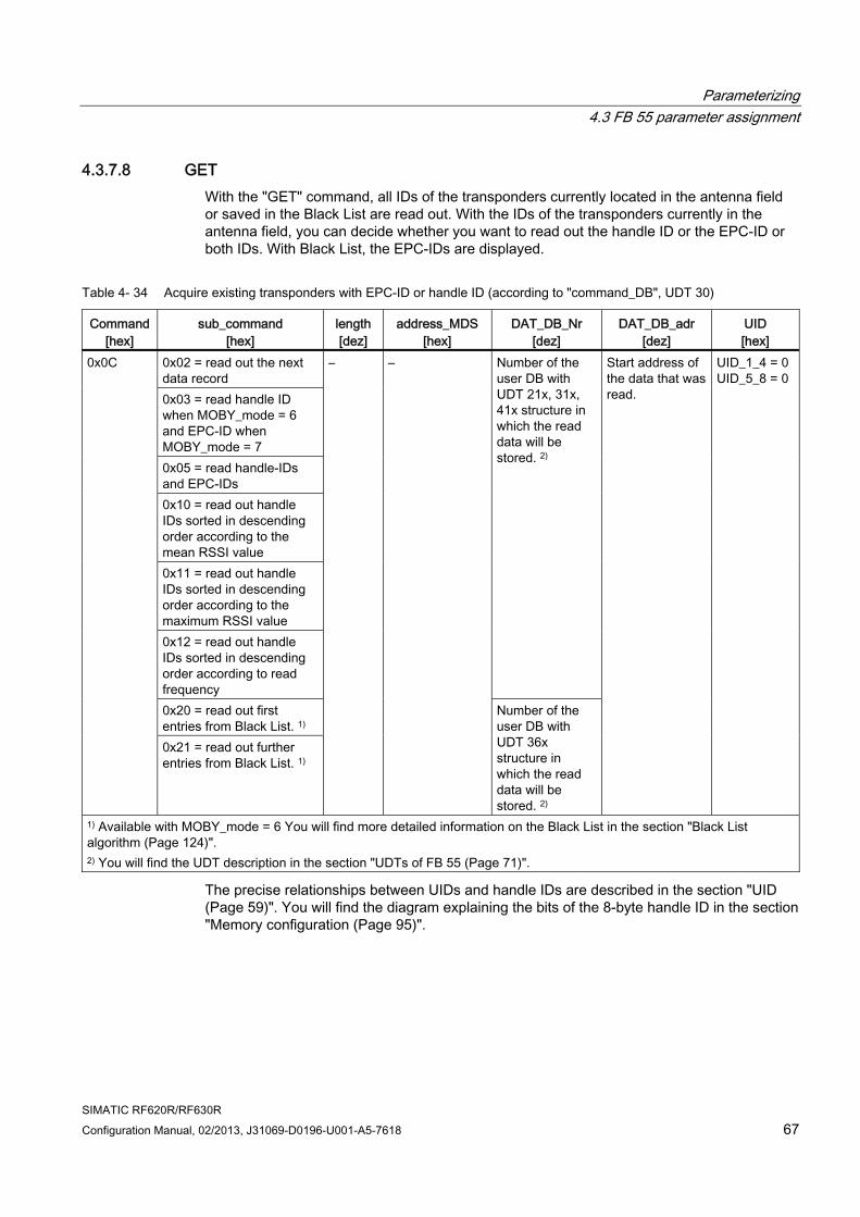
Parameterizing 4.3 FB 55 parameter assignment
SIMATIC RF620R/RF630R Configuration Manual, 02/2013, J31069-D0196-U001-A5-7618 67
4.3.7.8 GET With the "GET" command, all IDs of the transponders currently located in the antenna field or saved in the Black List are read out. With the IDs of the transponders currently in the antenna field, you can decide whether you want to read out the handle ID or the EPC-ID or both IDs. With Black List, the EPC-IDs are displayed.
Table 4- 34 Acquire existing transponders with EPC-ID or handle ID (according to "command_DB", UDT 30)
Command [hex]
sub_command [hex]
length[dez]
address_MDS [hex]
DAT_DB_Nr [dez]
DAT_DB_adr [dez]
UID [hex]
0x02 = read out the next data record 0x03 = read handle ID when MOBY_mode = 6 and EPC-ID when MOBY_mode = 7 0x05 = read handle-IDs and EPC-IDs 0x10 = read out handle IDs sorted in descending order according to the mean RSSI value 0x11 = read out handle IDs sorted in descending order according to the maximum RSSI value 0x12 = read out handle IDs sorted in descending order according to read frequency
Number of the user DB with UDT 21x, 31x, 41x structure in which the read data will be stored. 2)
0x20 = read out first entries from Black List. 1)
0x0C
0x21 = read out further entries from Black List. 1)
– –
Number of the user DB with UDT 36x structure in which the read data will be stored. 2)
Start address of the data that was read.
UID_1_4 = 0UID_5_8 = 0
1) Available with MOBY_mode = 6 You will find more detailed information on the Black List in the section "Black List algorithm (Page 124)". 2) You will find the UDT description in the section "UDTs of FB 55 (Page 71)".
The precise relationships between UIDs and handle IDs are described in the section "UID (Page 59)". You will find the diagram explaining the bits of the 8-byte handle ID in the section "Memory configuration (Page 95)".
Parameterizing 4.3 FB 55 parameter assignment
SIMATIC RF620R/RF630R 68 Configuration Manual, 02/2013, J31069-D0196-U001-A5-7618
If there are more transponders in the antenna field than can be transferred with one data record ("GET" command with sub_command 0x03, 0x05, 0x10, 0x11 and 0x12 or with sub_command 0x20), further data can be read out using the "sub_command = 0x02" or sub_command = 0x21. This procedure can be repeated until all transponder IDs have been read out. If all IDs have been read out and you start another query, you will obtain a success acknowledgement with no data content.
Note
The reader can only access a specific transponder within a bunch of them if the handle ID of the transponder in the antenna field is known.
"GET" command and handle-ID: • Read out handle IDs using "GET" with "sub_command = 0x03, 0x10, 0x11, 0x12" (or next
data record 0x02). Extract length of the EPC-ID from the handle ID (see section "UID (Page 59)").
• To read the EPC-ID, a "READ" command must be executed on the EPC MemBank with handle ID and EPC-ID length.
"GET" command and EPC-ID: • Read out handle IDs and EPC-IDs using "GET" with "sub_command = 0x05" (or next
data record 0x02). • Extracting EPC-IDs. The EPC-ID follows on directly after the 8-byte handle ID. The length
of the EPC-ID must be extracted from the handle ID (see section "UID (Page 59)").
Note MOBY_mode = 6 and validity of the handle ID after "GET" acknowledgements
Handle IDs are assigned the first time a transponder is detected. If the reader recognizes that the transponder is no longer valid, the handle ID also becomes invalid. When the same transponder is detected again, a new handle ID is assigned.
If the time between acknowledging the "GET" command and the subsequent "READ" or "WRITE" command is too long, handle IDs can lose their validity if the corresponding transponder has left the antenna field. If a transponder is accessed with an invalid handle ID, the error message "0x1D" is signaled.
Note
To allow the reader to recognize all the transponders in the antenna field as valid, it is advisable to make adequate time available between the "init_run" or "SET-ANT" commands and the "GET" command depending on the number of transponders.
Note Information on the use and parameter assignment of the Black List
You will find more detailed information on using the Black List and its parameter assignment in the section "Tag list (Page 114)".
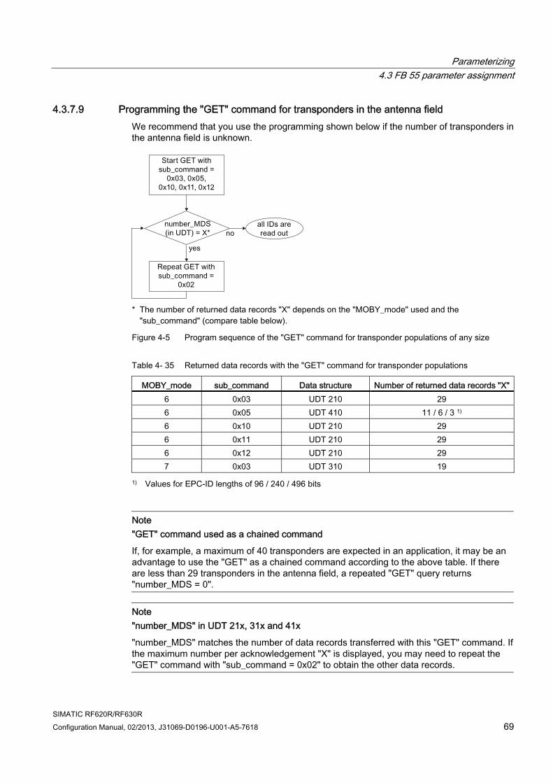
Parameterizing 4.3 FB 55 parameter assignment
SIMATIC RF620R/RF630R Configuration Manual, 02/2013, J31069-D0196-U001-A5-7618 69
4.3.7.9 Programming the "GET" command for transponders in the antenna field We recommend that you use the programming shown below if the number of transponders in the antenna field is unknown.
* The number of returned data records "X" depends on the "MOBY_mode" used and the
"sub_command" (compare table below).
Figure 4-5 Program sequence of the "GET" command for transponder populations of any size
Table 4- 35 Returned data records with the "GET" command for transponder populations
MOBY_mode sub_command Data structure Number of returned data records "X"6 0x03 UDT 210 29 6 0x05 UDT 410 11 / 6 / 3 1) 6 0x10 UDT 210 29 6 0x11 UDT 210 29 6 0x12 UDT 210 29 7 0x03 UDT 310 19
1) Values for EPC-ID lengths of 96 / 240 / 496 bits
Note "GET" command used as a chained command
If, for example, a maximum of 40 transponders are expected in an application, it may be an advantage to use the "GET" as a chained command according to the above table. If there are less than 29 transponders in the antenna field, a repeated "GET" query returns "number_MDS = 0".
Note "number_MDS" in UDT 21x, 31x and 41x
"number_MDS" matches the number of data records transferred with this "GET" command. If the maximum number per acknowledgement "X" is displayed, you may need to repeat the "GET" command with "sub_command = 0x02" to obtain the other data records.
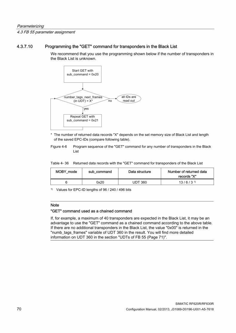
Parameterizing 4.3 FB 55 parameter assignment
SIMATIC RF620R/RF630R 70 Configuration Manual, 02/2013, J31069-D0196-U001-A5-7618
4.3.7.10 Programming the "GET" command for transponders in the Black List We recommend that you use the programming shown below if the number of transponders in the Black List is unknown.
* The number of returned data records "X" depends on the set memory size of Black List and length
of the saved EPC-IDs (compare following table).
Figure 4-6 Program sequence of the "GET" command for any number of transponders in the Black List
Table 4- 36 Returned data records with the "GET" command for transponders of the Black List
MOBY_mode sub_command Data structure Number of returned data records "X"
6 0x20 UDT 360 13 / 6 / 3 1)
1) Values for EPC-ID lengths of 96 / 240 / 496 bits
Note "GET" command used as a chained command
If, for example, a maximum of 40 transponders are expected in the Black List, it may be an advantage to use the "GET" command as a chained command according to the above table. If there are no additional transponders in the Black List, the value "0x00" is returned in the "numb_tags_frames" variable of UDT 360 in the result. You will find more detailed information on UDT 360 in the section "UDTs of FB 55 (Page 71)".

Parameterizing 4.3 FB 55 parameter assignment
SIMATIC RF620R/RF630R Configuration Manual, 02/2013, J31069-D0196-U001-A5-7618 71
4.3.8 UDTs of FB 55 The "MDS-/SLG-STATUS" commands return a variety of data. You can use the UDTs described in the following section for clear presentation and easy definition of the data blocks for the result.
UDT 300: Result of "SLG-STATUS" ("sub_command = 0x07")
Table 4- 37 UDT 300: "SLG-STATUS"
Address Name Type Comment 0.0 STRUCT +0.0 status_info BYTE SLG status mode +1.0 hardware CHAR Type of hardware +2.0 hardware_version WORD Version of hardware +4.0 reserved0 WORD +6.0 firmware CHAR Type of firmware +8.0 firmware_version WORD Version of firmware +10.0 driver CHAR Type of driver +12.0 current_time STRUCT Current time +0.0 hour BYTE Hours 1) +1.0 min BYTE Minutes 1) +2.0 sec BYTE Seconds 1) +3.0 reserved1 BYTE =4.0 END_STRUCT +16.0 SLG_version BYTE SLG version +17.0 baud BYTE Baudrate +18.0 reserved2 BYTE +19.0 distance_limiting_SLG BYTE Selected transmit power +20.0 multitag_SLG BYTE Multitag SLG +21.0 field_ON_control_SLG BYTE Selected comunication typ +22.0 field_ON_time_SLG BYTE Selected channel +23.0 expert_mode BYTE Expert mode +24.0 status_ant BYTE Status of antenna 2) +25.0 scanning_time_SLG BYTE Radio communication profile +26.0 MDS_control BYTE Presence mode =28.0 END_STRUCT
1) The internal time stamp of the internal reader clock that relates to this event is output. The internal reader clock is not synchronized with UTC.
2) The antenna status refers to the last executed "sub_command" command (bits 0 and 1) of "SET-ANT" or to the value preset by "init_run". In "init_run" of the RF620R, the default value is "1" (int. antenna on), with the RF630R, it is "3" (antennas 1 and 2 on).
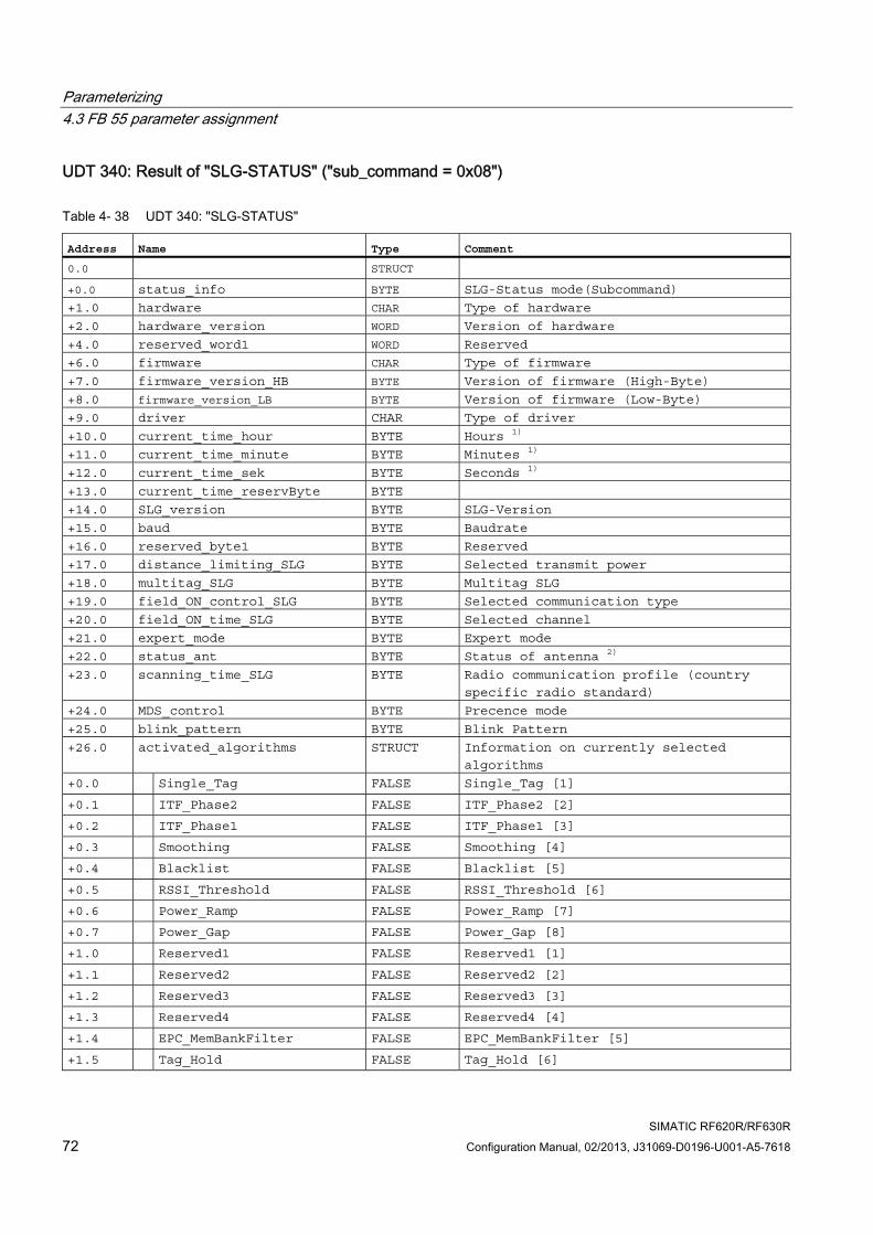
Parameterizing 4.3 FB 55 parameter assignment
SIMATIC RF620R/RF630R 72 Configuration Manual, 02/2013, J31069-D0196-U001-A5-7618
UDT 340: Result of "SLG-STATUS" ("sub_command = 0x08")
Table 4- 38 UDT 340: "SLG-STATUS"
Address Name Type Comment 0.0 STRUCT +0.0 status_info BYTE SLG-Status mode(Subcommand)
+1.0 hardware CHAR Type of hardware
+2.0 hardware_version WORD Version of hardware
+4.0 reserved_word1 WORD Reserved
+6.0 firmware CHAR Type of firmware
+7.0 firmware_version_HB BYTE Version of firmware (High-Byte)
+8.0 firmware_version_LB BYTE Version of firmware (Low-Byte)
+9.0 driver CHAR Type of driver
+10.0 current_time_hour BYTE Hours 1)
+11.0 current_time_minute BYTE Minutes 1)
+12.0 current_time_sek BYTE Seconds 1)
+13.0 current_time_reservByte BYTE
+14.0 SLG_version BYTE SLG-Version
+15.0 baud BYTE Baudrate
+16.0 reserved_byte1 BYTE Reserved
+17.0 distance_limiting_SLG BYTE Selected transmit power
+18.0 multitag_SLG BYTE Multitag SLG
+19.0 field_ON_control_SLG BYTE Selected communication type
+20.0 field_ON_time_SLG BYTE Selected channel
+21.0 expert_mode BYTE Expert mode
+22.0 status_ant BYTE Status of antenna 2)
+23.0 scanning_time_SLG BYTE Radio communication profile (country
specific radio standard)
+24.0 MDS_control BYTE Precence mode
+25.0 blink_pattern BYTE Blink Pattern
+26.0 activated_algorithms STRUCT Information on currently selected
algorithms
+0.0 Single_Tag FALSE Single_Tag [1]
+0.1 ITF_Phase2 FALSE ITF_Phase2 [2]
+0.2 ITF_Phase1 FALSE ITF_Phase1 [3]
+0.3 Smoothing FALSE Smoothing [4]
+0.4 Blacklist FALSE Blacklist [5]
+0.5 RSSI_Threshold FALSE RSSI_Threshold [6]
+0.6 Power_Ramp FALSE Power_Ramp [7]
+0.7 Power_Gap FALSE Power_Gap [8]
+1.0 Reserved1 FALSE Reserved1 [1]
+1.1 Reserved2 FALSE Reserved2 [2]
+1.2 Reserved3 FALSE Reserved3 [3]
+1.3 Reserved4 FALSE Reserved4 [4]
+1.4 EPC_MemBankFilter FALSE EPC_MemBankFilter [5]
+1.5 Tag_Hold FALSE Tag_Hold [6]
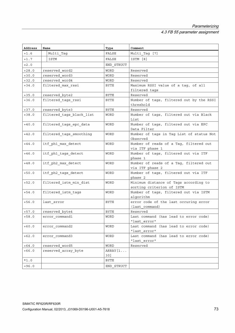
Parameterizing 4.3 FB 55 parameter assignment
SIMATIC RF620R/RF630R Configuration Manual, 02/2013, J31069-D0196-U001-A5-7618 73
Address Name Type Comment +1.6 Multi_Tag FALSE Multi_Tag [7]
+1.7 ISTM FALSE ISTM [8]
=2.0 END_STRUCT +28.0 reserved_word2 WORD Reserved
+30.0 reserved_word3 WORD Reserved
+32.0 reserved_word4 WORD Reserved
+34.0 filtered_max_rssi BYTE Maximum RSSI value of a tag, of all
filtered tags
+35.0 reserved_byte2 BYTE Reserved
+36.0 filtered_tags_rssi BYTE Number of tags, filtered out by the RSSI
threshold
+37.0 reserved_byte3 BYTE Reserved
+38.0 filtered_tags_black_list WORD Number of tags, filtered out via Black
List
+40.0 filtered_tags_epc_data WORD Number of tags, filtered out via EPC
Data Filter
+42.0 filtered_tags_smoothing WORD Number of tags in Tag List of status Not
Observed
+44.0 itf_ph1_max_detect WORD Number of reads of a Tag, filtered out
via ITF phase 1
+46.0 itf_ph1_tags_detect WORD Number of tags, filtered out via ITF
phase 1
+48.0 itf_ph2_max_detect WORD Number of reads of a Tag, filtered out
via ITF phase 2
+50.0 itf_ph2_tags_detect WORD Number of tags, filtered out via ITF
phase 2
+52.0 filtered_istm_min_dist WORD Minimum distance of Tags according to
sorting criterion of ISTM
+54.0 filtered_istm_tags WORD Number of tags, filtered out via ISTM
algorithm
+56.0 last_error BYTE error code of the last occuring error
(last_command)
+57.0 reserved_byte4 BYTE Reserved
+58.0 error_command1 WORD Last command (has lead to error code)
"last_error"
+60.0 error_command2 WORD Last command (has lead to error code)
"last_error"
+62.0 error_command3 WORD Last command (has lead to error code)
"last_error"
+64.0 reserved_word5 WORD Reserved
+66.0 reserved_array_byte ARRAY[1...
30]
*1.0 BYTE =96.0 END_STRUCT
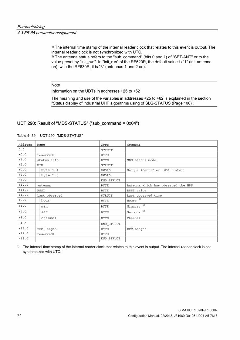
Parameterizing 4.3 FB 55 parameter assignment
SIMATIC RF620R/RF630R 74 Configuration Manual, 02/2013, J31069-D0196-U001-A5-7618
1) The internal time stamp of the internal reader clock that relates to this event is output. The internal reader clock is not synchronized with UTC. 2) The antenna status refers to the "sub_command" (bits 0 and 1) of "SET-ANT" or to the value preset by "init_run". In "init_run" of the RF620R, the default value is "1" (int. antenna on), with the RF630R, it is "3" (antennas 1 and 2 on).
Note Information on the UDTs in addresses +25 to +62
The meaning and use of the variables in addresses +25 to +62 is explained in the section "Status display of industrial UHF algorithms using of SLG-STATUS (Page 106)".
UDT 290: Result of "MDS-STATUS" ("sub_command = 0x04")
Table 4- 39 UDT 290: "MDS-STATUS"
Address Name Type Comment 0.0 STRUCT +0.0 reserved0 BYTE +1.0 status_info BYTE MDS status mode +2.0 UID STRUCT +0.0 Byte_1_4 DWORD +4.0 Byte_5_8 DWORD
Unique identifier (MDS number)
=8.0 END_STRUCT +10.0 antenna BYTE Antenna which has observed the MDS +11.0 RSSI BYTE RSSI value +12.0 last_observed STRUCT Last observed time +0.0 hour BYTE Hours 1)
+1.0 min BYTE Minutes 1)
+2.0 sec BYTE Seconds 1)
+3.0 channel BYTE Channel
=4.0 END_STRUCT +16.0 EPC_length BYTE EPC-Length +17.0 reserved1 BYTE =18.0 END_STRUCT
1) The internal time stamp of the internal reader clock that relates to this event is output. The internal reader clock is not synchronized with UTC.
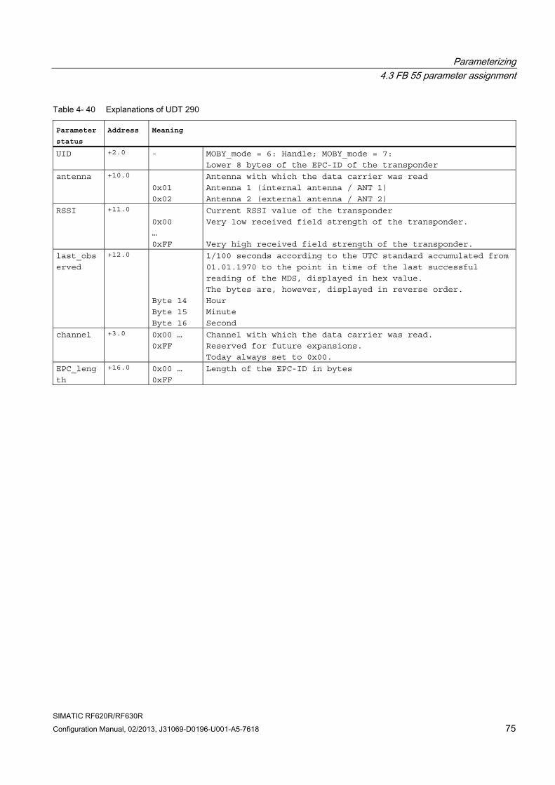
Parameterizing 4.3 FB 55 parameter assignment
SIMATIC RF620R/RF630R Configuration Manual, 02/2013, J31069-D0196-U001-A5-7618 75
Table 4- 40 Explanations of UDT 290
Parameter
status Address Meaning
UID +2.0 - MOBY_mode = 6: Handle; MOBY_mode = 7:
Lower 8 bytes of the EPC-ID of the transponder
antenna +10.0
0x01
0x02
Antenna with which the data carrier was read
Antenna 1 (internal antenna / ANT 1)
Antenna 2 (external antenna / ANT 2)
RSSI +11.0
0x00
…
0xFF
Current RSSI value of the transponder
Very low received field strength of the transponder.
Very high received field strength of the transponder.
last_obs
erved
+12.0
Byte 14
Byte 15
Byte 16
1/100 seconds according to the UTC standard accumulated from
01.01.1970 to the point in time of the last successful
reading of the MDS, displayed in hex value.
The bytes are, however, displayed in reverse order.
Hour
Minute
Second
channel +3.0 0x00 …
0xFF
Channel with which the data carrier was read.
Reserved for future expansions.
Today always set to 0x00.
EPC_leng
th
+16.0 0x00 …
0xFF
Length of the EPC-ID in bytes
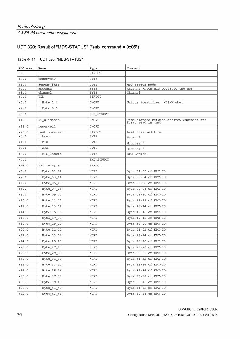
Parameterizing 4.3 FB 55 parameter assignment
SIMATIC RF620R/RF630R 76 Configuration Manual, 02/2013, J31069-D0196-U001-A5-7618
UDT 320: Result of "MDS-STATUS" ("sub_command = 0x05")
Table 4- 41 UDT 320: "MDS-STATUS"
Address Name Type Comment 0.0 STRUCT +0.0 reserved0 BYTE +1.0 status_info BYTE MDS status mode +2.0 antenna BYTE Antenna which has observed the MDS +3.0 channel BYTE Channel +4.0 UID STRUCT +0.0 Byte_1_4 DWORD Unique identifier (MDS-Number) +4.0 Byte_5_8 DWORD =8.0 END_STRUCT +12.0 DT_glimpsed DWORD Time elapsed between achknowledgement and
first read in [ms] +16.0 reserved1 DWORD +20.0 last_observed STRUCT Last observed time +0.0 hour BYTE Hours 1) +1.0 min BYTE Minutes 1) +2.0 sec BYTE Seconds 1) +3.0 EPC_length BYTE EPC-Length =4.0 END_STRUCT +24.0 EPC_ID_Byte STRUCT +0.0 Byte_01_02 WORD Byte 01-02 of EPC-ID +2.0 Byte_03_04 WORD Byte 03-04 of EPC-ID +4.0 Byte_05_06 WORD Byte 05-06 of EPC-ID +6.0 Byte_07_08 WORD Byte 07-08 of EPC-ID +8.0 Byte_09_10 WORD Byte 09-10 of EPC-ID +10.0 Byte_11_12 WORD Byte 11-12 of EPC-ID +12.0 Byte_13_14 WORD Byte 13-14 of EPC-ID +14.0 Byte_15_16 WORD Byte 15-16 of EPC-ID +16.0 Byte_17_18 WORD Byte 17-18 of EPC-ID +18.0 Byte_19_20 WORD Byte 19-20 of EPC-ID +20.0 Byte_21_22 WORD Byte 21-22 of EPC-ID +22.0 Byte_23_24 WORD Byte 23-24 of EPC-ID +24.0 Byte_25_26 WORD Byte 25-26 of EPC-ID +26.0 Byte_27_28 WORD Byte 27-28 of EPC-ID +28.0 Byte_29_30 WORD Byte 29-30 of EPC-ID +30.0 Byte_31_32 WORD Byte 31-32 of EPC-ID +32.0 Byte_33_34 WORD Byte 33-34 of EPC-ID +34.0 Byte_35_36 WORD Byte 35-36 of EPC-ID +36.0 Byte_37_38 WORD Byte 37-38 of EPC-ID +38.0 Byte_39_40 WORD Byte 39-40 of EPC-ID +40.0 Byte_41_42 WORD Byte 41-42 of EPC-ID +42.0 Byte_43_44 WORD Byte 43-44 of EPC-ID
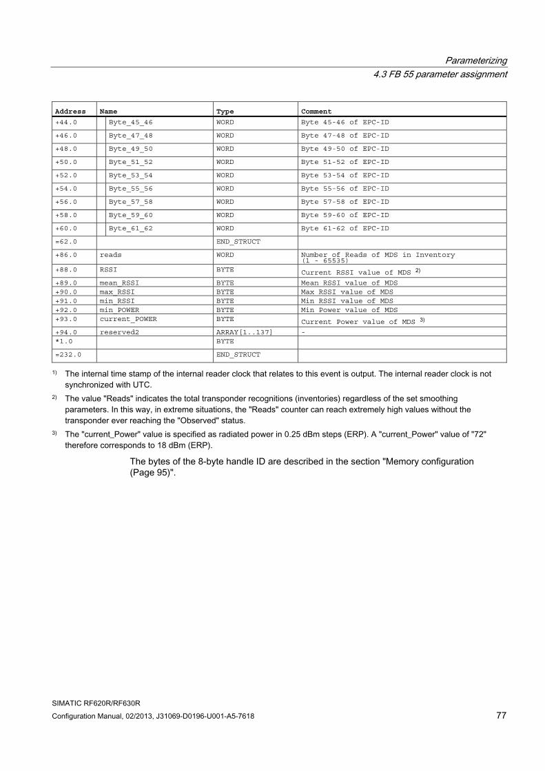
Parameterizing 4.3 FB 55 parameter assignment
SIMATIC RF620R/RF630R Configuration Manual, 02/2013, J31069-D0196-U001-A5-7618 77
Address Name Type Comment +44.0 Byte_45_46 WORD Byte 45-46 of EPC-ID +46.0 Byte_47_48 WORD Byte 47-48 of EPC-ID +48.0 Byte_49_50 WORD Byte 49-50 of EPC-ID +50.0 Byte_51_52 WORD Byte 51-52 of EPC-ID +52.0 Byte_53_54 WORD Byte 53-54 of EPC-ID +54.0 Byte_55_56 WORD Byte 55-56 of EPC-ID +56.0 Byte_57_58 WORD Byte 57-58 of EPC-ID +58.0 Byte_59_60 WORD Byte 59-60 of EPC-ID +60.0 Byte_61_62 WORD Byte 61-62 of EPC-ID =62.0 END_STRUCT +86.0 reads WORD Number of Reads of MDS in Inventory
(1 - 65535) +88.0 RSSI BYTE Current RSSI value of MDS 2) +89.0 mean_RSSI BYTE Mean RSSI value of MDS +90.0 max_RSSI BYTE Max RSSI value of MDS +91.0 min_RSSI BYTE Min RSSI value of MDS +92.0 min_POWER BYTE Min Power value of MDS +93.0 current_POWER BYTE Current Power value of MDS 3) +94.0 reserved2 ARRAY[1..137] - *1.0 BYTE =232.0 END_STRUCT
1) The internal time stamp of the internal reader clock that relates to this event is output. The internal reader clock is not synchronized with UTC.
2) The value "Reads" indicates the total transponder recognitions (inventories) regardless of the set smoothing parameters. In this way, in extreme situations, the "Reads" counter can reach extremely high values without the transponder ever reaching the "Observed" status.
3) The "current_Power" value is specified as radiated power in 0.25 dBm steps (ERP). A "current_Power" value of "72" therefore corresponds to 18 dBm (ERP).
The bytes of the 8-byte handle ID are described in the section "Memory configuration (Page 95)".
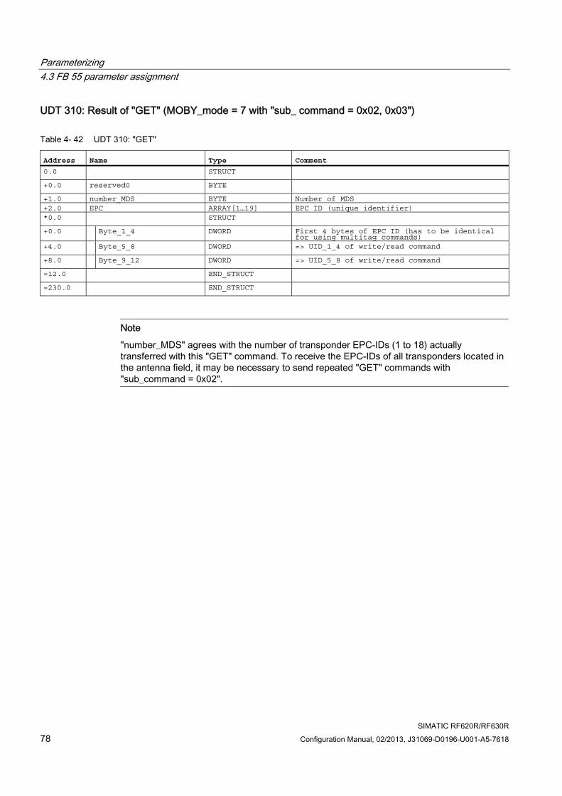
Parameterizing 4.3 FB 55 parameter assignment
SIMATIC RF620R/RF630R 78 Configuration Manual, 02/2013, J31069-D0196-U001-A5-7618
UDT 310: Result of "GET" (MOBY_mode = 7 with "sub_ command = 0x02, 0x03")
Table 4- 42 UDT 310: "GET"
Address Name Type Comment 0.0 STRUCT +0.0 reserved0 BYTE +1.0 number_MDS BYTE Number of MDS +2.0 EPC ARRAY[1…19] EPC ID (unique identifier) *0.0 STRUCT +0.0 Byte_1_4 DWORD First 4 bytes of EPC ID (has to be identical
for using multitag commands) +4.0 Byte_5_8 DWORD => UID_1_4 of write/read command +8.0 Byte_9_12 DWORD => UID_5_8 of write/read command =12.0 END_STRUCT =230.0 END_STRUCT
Note
"number_MDS" agrees with the number of transponder EPC-IDs (1 to 18) actually transferred with this "GET" command. To receive the EPC-IDs of all transponders located in the antenna field, it may be necessary to send repeated "GET" commands with "sub_command = 0x02".
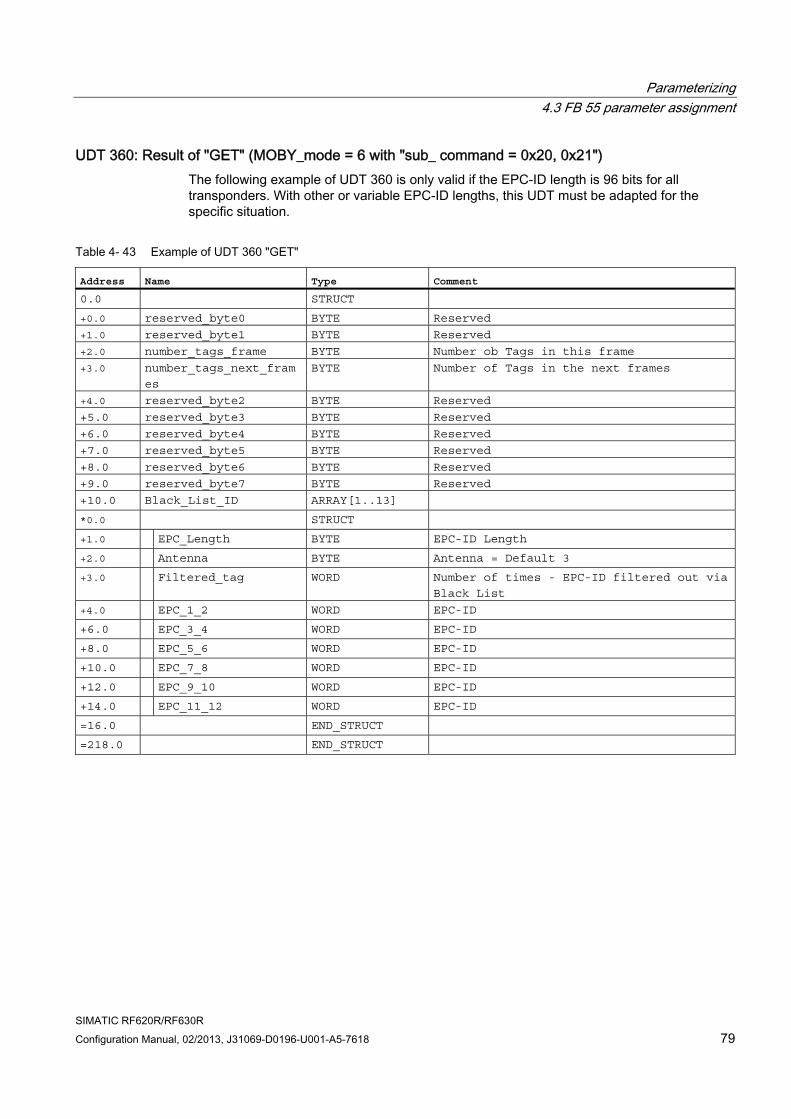
Parameterizing 4.3 FB 55 parameter assignment
SIMATIC RF620R/RF630R Configuration Manual, 02/2013, J31069-D0196-U001-A5-7618 79
UDT 360: Result of "GET" (MOBY_mode = 6 with "sub_ command = 0x20, 0x21") The following example of UDT 360 is only valid if the EPC-ID length is 96 bits for all transponders. With other or variable EPC-ID lengths, this UDT must be adapted for the specific situation.
Table 4- 43 Example of UDT 360 "GET"
Address Name Type Comment 0.0 STRUCT +0.0 reserved_byte0 BYTE Reserved
+1.0 reserved_byte1 BYTE Reserved
+2.0 number_tags_frame BYTE Number ob Tags in this frame
+3.0 number_tags_next_fram
es
BYTE Number of Tags in the next frames
+4.0 reserved_byte2 BYTE Reserved
+5.0 reserved_byte3 BYTE Reserved
+6.0 reserved_byte4 BYTE Reserved
+7.0 reserved_byte5 BYTE Reserved
+8.0 reserved_byte6 BYTE Reserved
+9.0 reserved_byte7 BYTE Reserved
+10.0 Black_List_ID ARRAY[1..13] *0.0 STRUCT +1.0 EPC_Length BYTE EPC-ID Length
+2.0 Antenna BYTE Antenna = Default 3
+3.0 Filtered_tag WORD Number of times - EPC-ID filtered out via
Black List
+4.0 EPC_1_2 WORD EPC-ID
+6.0 EPC_3_4 WORD EPC-ID
+8.0 EPC_5_6 WORD EPC-ID
+10.0 EPC_7_8 WORD EPC-ID
+12.0 EPC_9_10 WORD EPC-ID
+14.0 EPC_11_12 WORD EPC-ID
=16.0 END_STRUCT =218.0 END_STRUCT
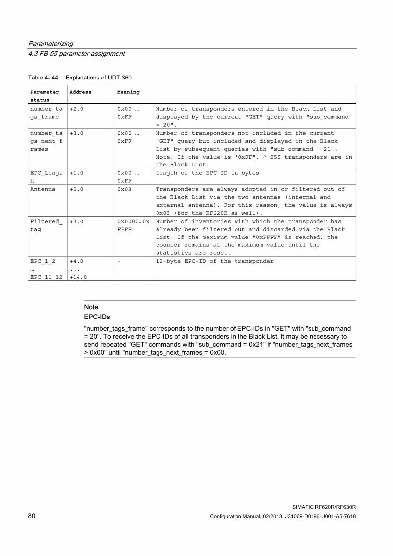
Parameterizing 4.3 FB 55 parameter assignment
SIMATIC RF620R/RF630R 80 Configuration Manual, 02/2013, J31069-D0196-U001-A5-7618
Table 4- 44 Explanations of UDT 360
Parameter
status Address Meaning
number_ta
gs_frame
+2.0 0x00 …
0xFF
Number of transponders entered in the Black List and
displayed by the current "GET" query with "sub_command
= 20".
number_ta
gs_next_f
rames
+3.0 0x00 …
0xFF
Number of transponders not included in the current
"GET" query but included and displayed in the Black
List by subsequent queries with "sub_command = 21".
Note: If the value is "0xFF", ≥ 255 transponders are in the Black List.
EPC_Lengt
h
+1.0 0x00 …
0xFF
Length of the EPC-ID in bytes
Antenna +2.0 0x03 Transponders are always adopted in or filtered out of
the Black List via the two antennas (internal and
external antenna). For this reason, the value is always
0x03 (for the RF620R as well).
Filtered_
tag
+3.0 0x0000…0x
FFFF
Number of inventories with which the transponder has
already been filtered out and discarded via the Black
List. If the maximum value "0xFFFF" is reached, the
counter remains at the maximum value until the
statistics are reset.
EPC_1_2
…
EPC_11_12
+4.0
...
+14.0
- 12-byte EPC-ID of the transponder
Note EPC-IDs
"number_tags_frame" corresponds to the number of EPC-IDs in "GET" with "sub_command = 20". To receive the EPC-IDs of all transponders in the Black List, it may be necessary to send repeated "GET" commands with "sub_command = 0x21" if "number_tags_next_frames > 0x00" until "number_tags_next_frames = 0x00.
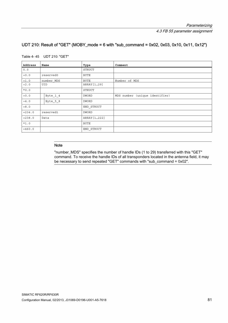
Parameterizing 4.3 FB 55 parameter assignment
SIMATIC RF620R/RF630R Configuration Manual, 02/2013, J31069-D0196-U001-A5-7618 81
UDT 210: Result of "GET" (MOBY_mode = 6 with "sub_command = 0x02, 0x03, 0x10, 0x11, 0x12")
Table 4- 45 UDT 210: "GET"
Address Name Type Comment 0.0 STRUCT +0.0 reserved0 BYTE +1.0 number_MDS BYTE Number of MDS +2.0 UID ARRAY[1…29] *0.0 STRUCT +0.0 Byte_1_4 DWORD MDS number (unique identifier) +4.0 Byte_5_8 DWORD =8.0 END_STRUCT +234.0 reserved1 DWORD +238.0 Data ARRAY[1…222] *1.0 BYTE =460.0 END_STRUCT
Note
"number_MDS" specifies the number of handle IDs (1 to 29) transferred with this "GET" command. To receive the handle IDs of all transponders located in the antenna field, it may be necessary to send repeated "GET" commands with "sub_command = 0x02".
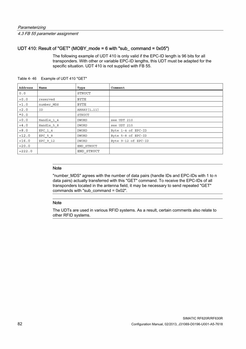
Parameterizing 4.3 FB 55 parameter assignment
SIMATIC RF620R/RF630R 82 Configuration Manual, 02/2013, J31069-D0196-U001-A5-7618
UDT 410: Result of "GET" (MOBY_mode = 6 with "sub_ command = 0x05") The following example of UDT 410 is only valid if the EPC-ID length is 96 bits for all transponders. With other or variable EPC-ID lengths, this UDT must be adapted for the specific situation. UDT 410 is not supplied with FB 55.
Table 4- 46 Example of UDT 410 "GET"
Address Name Type Comment 0.0 STRUCT +0.0 reserved BYTE
+1.0 number_MDS BYTE
+2.0 ID ARRAY[1…11]
*0.0 STRUCT
+0.0 Handle_1_4 DWORD see UDT 210
+4.0 Handle_5_8 DWORD see UDT 210
+8.0 EPC_1_4 DWORD Byte 1-4 of EPC-ID
+12.0 EPC_5_8 DWORD Byte 5-8 of EPC-ID
+16.0 EPC_9_12 DWORD Byte 9-12 of EPC-ID
=20.0 END_STRUCT
=222.0 END_STRUCT
Note
"number_MDS" agrees with the number of data pairs (handle IDs and EPC-IDs with 1 to n data pairs) actually transferred with this "GET" command. To receive the EPC-IDs of all transponders located in the antenna field, it may be necessary to send repeated "GET" commands with "sub_command = 0x02".
Note
The UDTs are used in various RFID systems. As a result, certain comments also relate to other RFID systems.
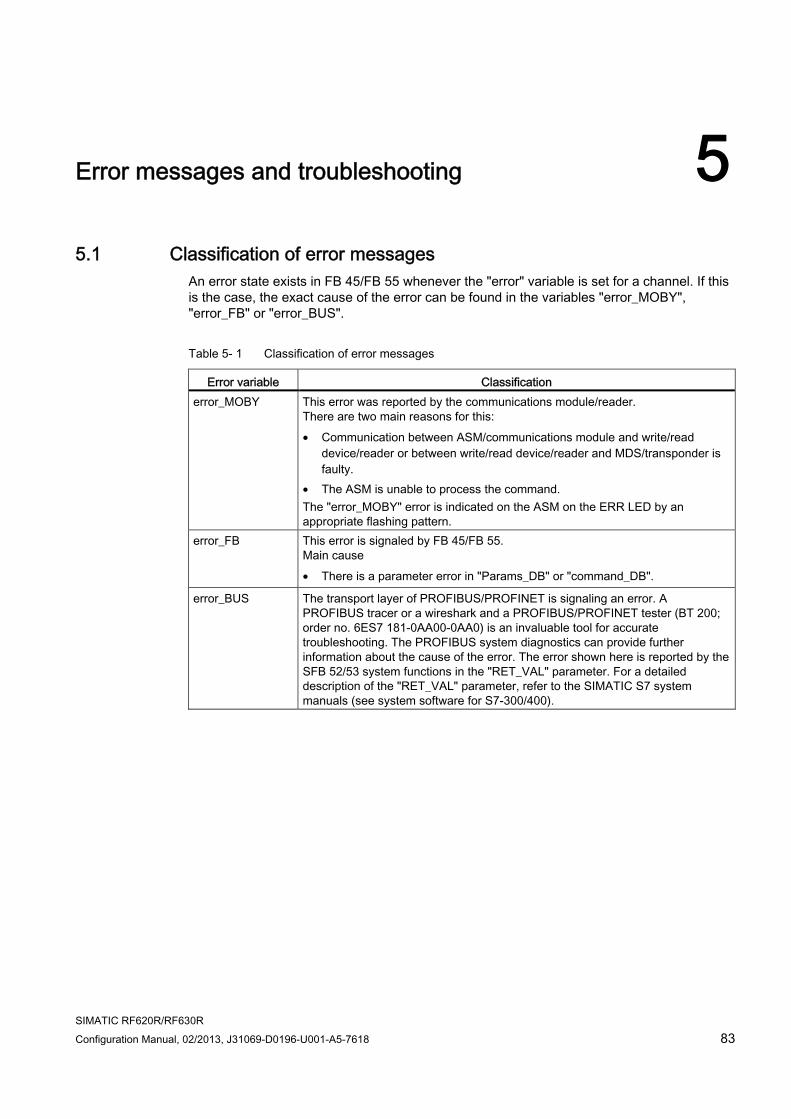
SIMATIC RF620R/RF630R Configuration Manual, 02/2013, J31069-D0196-U001-A5-7618 83
Error messages and troubleshooting 55.1 Classification of error messages
An error state exists in FB 45/FB 55 whenever the "error" variable is set for a channel. If this is the case, the exact cause of the error can be found in the variables "error_MOBY", "error_FB" or "error_BUS".
Table 5- 1 Classification of error messages
Error variable Classification error_MOBY This error was reported by the communications module/reader.
There are two main reasons for this: • Communication between ASM/communications module and write/read
device/reader or between write/read device/reader and MDS/transponder is faulty.
• The ASM is unable to process the command. The "error_MOBY" error is indicated on the ASM on the ERR LED by an appropriate flashing pattern.
error_FB This error is signaled by FB 45/FB 55. Main cause • There is a parameter error in "Params_DB" or "command_DB".
error_BUS The transport layer of PROFIBUS/PROFINET is signaling an error. A PROFIBUS tracer or a wireshark and a PROFIBUS/PROFINET tester (BT 200; order no. 6ES7 181-0AA00-0AA0) is an invaluable tool for accurate troubleshooting. The PROFIBUS system diagnostics can provide further information about the cause of the error. The error shown here is reported by the SFB 52/53 system functions in the "RET_VAL" parameter. For a detailed description of the "RET_VAL" parameter, refer to the SIMATIC S7 system manuals (see system software for S7-300/400).
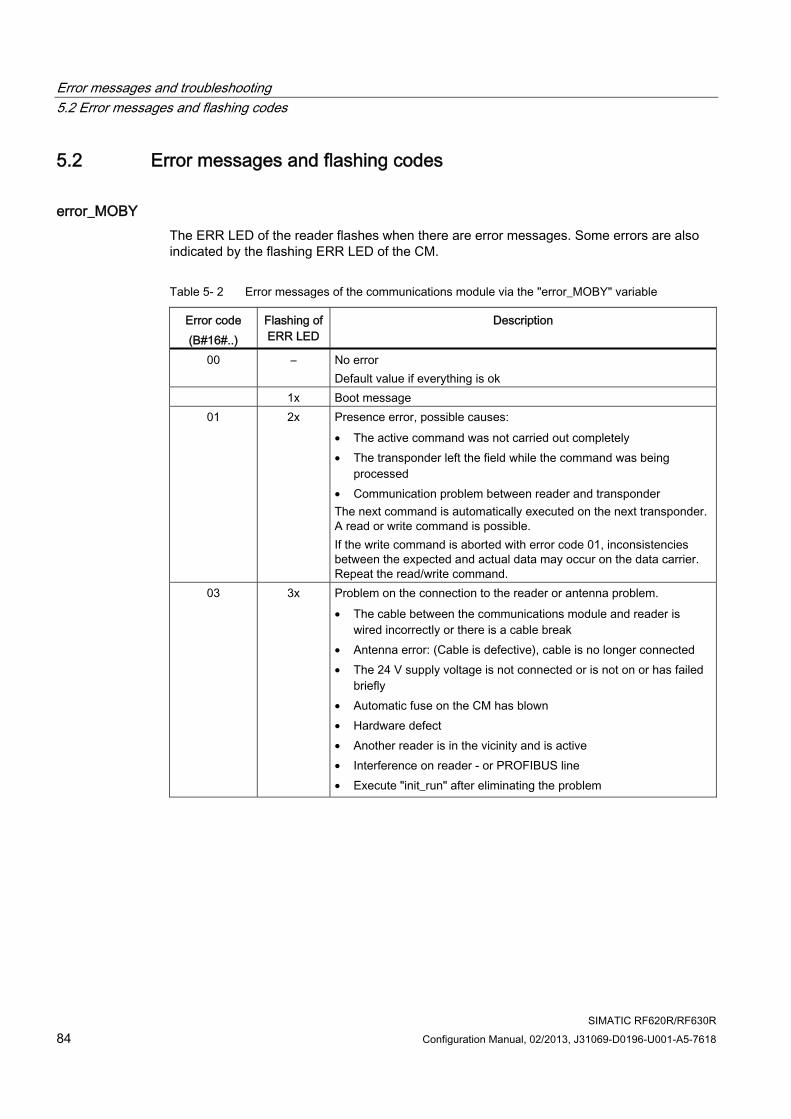
Error messages and troubleshooting 5.2 Error messages and flashing codes
SIMATIC RF620R/RF630R 84 Configuration Manual, 02/2013, J31069-D0196-U001-A5-7618
5.2 Error messages and flashing codes
error_MOBY The ERR LED of the reader flashes when there are error messages. Some errors are also indicated by the flashing ERR LED of the CM.
Table 5- 2 Error messages of the communications module via the "error_MOBY" variable
Error code (B#16#..)
Flashing of ERR LED
Description
00 – No error Default value if everything is ok
1x Boot message 01 2x Presence error, possible causes:
• The active command was not carried out completely • The transponder left the field while the command was being
processed • Communication problem between reader and transponder The next command is automatically executed on the next transponder. A read or write command is possible. If the write command is aborted with error code 01, inconsistencies between the expected and actual data may occur on the data carrier. Repeat the read/write command.
03 3x Problem on the connection to the reader or antenna problem. • The cable between the communications module and reader is
wired incorrectly or there is a cable break • Antenna error: (Cable is defective), cable is no longer connected • The 24 V supply voltage is not connected or is not on or has failed
briefly • Automatic fuse on the CM has blown • Hardware defect • Another reader is in the vicinity and is active • Interference on reader - or PROFIBUS line • Execute "init_run" after eliminating the problem
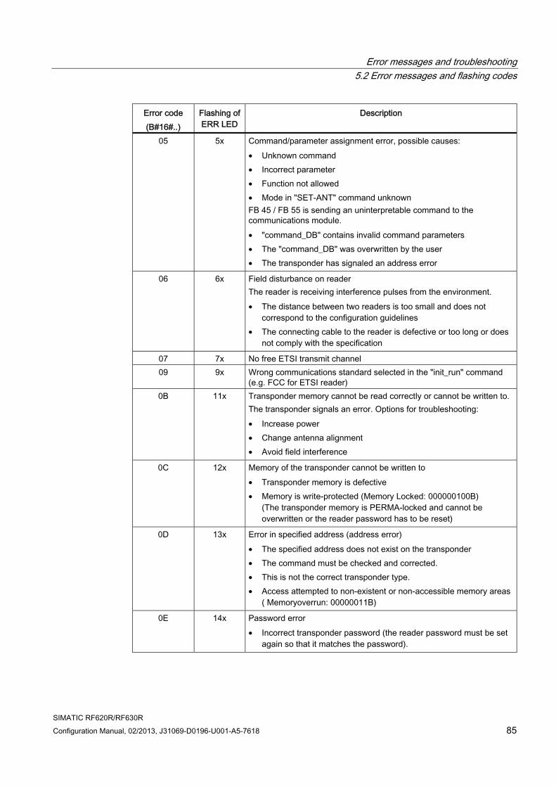
Error messages and troubleshooting 5.2 Error messages and flashing codes
SIMATIC RF620R/RF630R Configuration Manual, 02/2013, J31069-D0196-U001-A5-7618 85
Error code (B#16#..)
Flashing of ERR LED
Description
05 5x Command/parameter assignment error, possible causes: • Unknown command • Incorrect parameter • Function not allowed • Mode in "SET-ANT" command unknown FB 45 / FB 55 is sending an uninterpretable command to the communications module. • "command_DB" contains invalid command parameters • The "command_DB" was overwritten by the user • The transponder has signaled an address error
06 6x Field disturbance on reader The reader is receiving interference pulses from the environment. • The distance between two readers is too small and does not
correspond to the configuration guidelines • The connecting cable to the reader is defective or too long or does
not comply with the specification
07 7x No free ETSI transmit channel 09 9x Wrong communications standard selected in the "init_run" command
(e.g. FCC for ETSI reader) 0B 11x Transponder memory cannot be read correctly or cannot be written to.
The transponder signals an error. Options for troubleshooting: • Increase power • Change antenna alignment • Avoid field interference
0C 12x Memory of the transponder cannot be written to • Transponder memory is defective • Memory is write-protected (Memory Locked: 000000100B)
(The transponder memory is PERMA-locked and cannot be overwritten or the reader password has to be reset)
0D 13x Error in specified address (address error) • The specified address does not exist on the transponder • The command must be checked and corrected. • This is not the correct transponder type. • Access attempted to non-existent or non-accessible memory areas
( Memoryoverrun: 00000011B)
0E 14x Password error • Incorrect transponder password (the reader password must be set
again so that it matches the password).
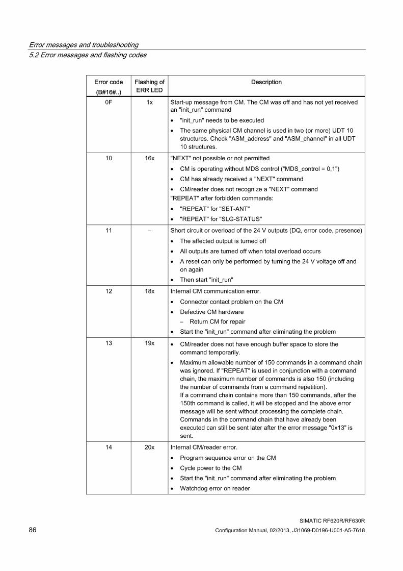
Error messages and troubleshooting 5.2 Error messages and flashing codes
SIMATIC RF620R/RF630R 86 Configuration Manual, 02/2013, J31069-D0196-U001-A5-7618
Error code (B#16#..)
Flashing of ERR LED
Description
0F 1x Start-up message from CM. The CM was off and has not yet received an "init_run" command • "init_run" needs to be executed • The same physical CM channel is used in two (or more) UDT 10
structures. Check "ASM_address" and "ASM_channel" in all UDT 10 structures.
10 16x "NEXT" not possible or not permitted • CM is operating without MDS control ("MDS_control = 0,1") • CM has already received a "NEXT" command • CM/reader does not recognize a "NEXT" command "REPEAT" after forbidden commands: • "REPEAT" for "SET-ANT" • "REPEAT" for "SLG-STATUS"
11 – Short circuit or overload of the 24 V outputs (DQ, error code, presence)• The affected output is turned off • All outputs are turned off when total overload occurs • A reset can only be performed by turning the 24 V voltage off and
on again • Then start "init_run"
12 18x Internal CM communication error. • Connector contact problem on the CM • Defective CM hardware
– Return CM for repair • Start the "init_run" command after eliminating the problem
13 19x • CM/reader does not have enough buffer space to store the command temporarily.
• Maximum allowable number of 150 commands in a command chain was ignored. If "REPEAT" is used in conjunction with a command chain, the maximum number of commands is also 150 (including the number of commands from a command repetition). If a command chain contains more than 150 commands, after the 150th command is called, it will be stopped and the above error message will be sent without processing the complete chain. Commands in the command chain that have already been executed can still be sent later after the error message "0x13" is sent.
14 20x Internal CM/reader error. • Program sequence error on the CM • Cycle power to the CM • Start the "init_run" command after eliminating the problem • Watchdog error on reader
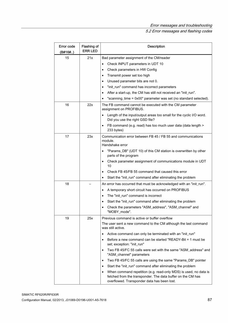
Error messages and troubleshooting 5.2 Error messages and flashing codes
SIMATIC RF620R/RF630R Configuration Manual, 02/2013, J31069-D0196-U001-A5-7618 87
Error code (B#16#..)
Flashing of ERR LED
Description
15 21x Bad parameter assignment of the CM/reader • Check INPUT parameters in UDT 10 • Check parameters in HW Config • Transmit power set too high • Unused parameter bits are not 0. • "init_run" command has incorrect parameters • After a start-up, the CM has still not received an "init_run". • "scanning_time = 0x00" parameter was set (no standard selected).
16 22x The FB command cannot be executed with the CM parameter assignment on PROFIBUS. • Length of the input/output areas too small for the cyclic I/O word.
Did you use the right GSD file? • FB command (e.g. read) has too much user data (data length >
233 bytes)
17 23x Communication error between FB 45 / FB 55 and communications module. Handshake error • "Params_DB" (UDT 10) of this CM station is overwritten by other
parts of the program • Check parameter assignment of communications module in UDT
10 • Check FB 45/FB 55 command that caused this error • Start the "init_run" command after eliminating the problem
18 – An error has occurred that must be acknowledged with an "init_run". • A temporary short circuit has occurred on PROFIBUS • The "init_run" command is incorrect • Start the "init_run" command after eliminating the problem • Check the parameters "ASM_address", "ASM_channel" and
"MOBY_mode".
19 25x Previous command is active or buffer overflow The user sent a new command to the CM although the last command was still active. • Active command can only be terminated with an "init_run" • Before a new command can be started "READY-Bit = 1 must be
set; exception: "init_run" • Two FB 45/FC 55 calls were set with the same "ASM_address" and
"ASM_channel" parameters • Two FB 45/FC 55 calls are using the same "Params_DB" pointer • Start the "init_run" command after eliminating the problem • When command repetition (e.g. read-only MDS) is used, no data is
fetched from the transponder. The data buffer on the CM has overflowed. Transponder data has been lost.
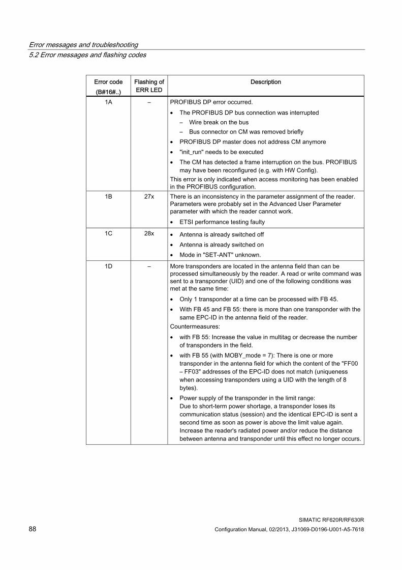
Error messages and troubleshooting 5.2 Error messages and flashing codes
SIMATIC RF620R/RF630R 88 Configuration Manual, 02/2013, J31069-D0196-U001-A5-7618
Error code (B#16#..)
Flashing of ERR LED
Description
1A – PROFIBUS DP error occurred. • The PROFIBUS DP bus connection was interrupted
– Wire break on the bus – Bus connector on CM was removed briefly
• PROFIBUS DP master does not address CM anymore • "init_run" needs to be executed • The CM has detected a frame interruption on the bus. PROFIBUS
may have been reconfigured (e.g. with HW Config). This error is only indicated when access monitoring has been enabled in the PROFIBUS configuration.
1B 27x There is an inconsistency in the parameter assignment of the reader. Parameters were probably set in the Advanced User Parameter parameter with which the reader cannot work. • ETSI performance testing faulty
1C 28x • Antenna is already switched off • Antenna is already switched on • Mode in "SET-ANT" unknown.
1D – More transponders are located in the antenna field than can be processed simultaneously by the reader. A read or write command was sent to a transponder (UID) and one of the following conditions was met at the same time: • Only 1 transponder at a time can be processed with FB 45. • With FB 45 and FB 55: there is more than one transponder with the
same EPC-ID in the antenna field of the reader. Countermeasures: • with FB 55: Increase the value in multitag or decrease the number
of transponders in the field. • with FB 55 (with MOBY_mode = 7): There is one or more
transponder in the antenna field for which the content of the "FF00 – FF03" addresses of the EPC-ID does not match (uniqueness when accessing transponders using a UID with the length of 8 bytes).
• Power supply of the transponder in the limit range: Due to short-term power shortage, a transponder loses its communication status (session) and the identical EPC-ID is sent a second time as soon as power is above the limit value again. Increase the reader's radiated power and/or reduce the distance between antenna and transponder until this effect no longer occurs.
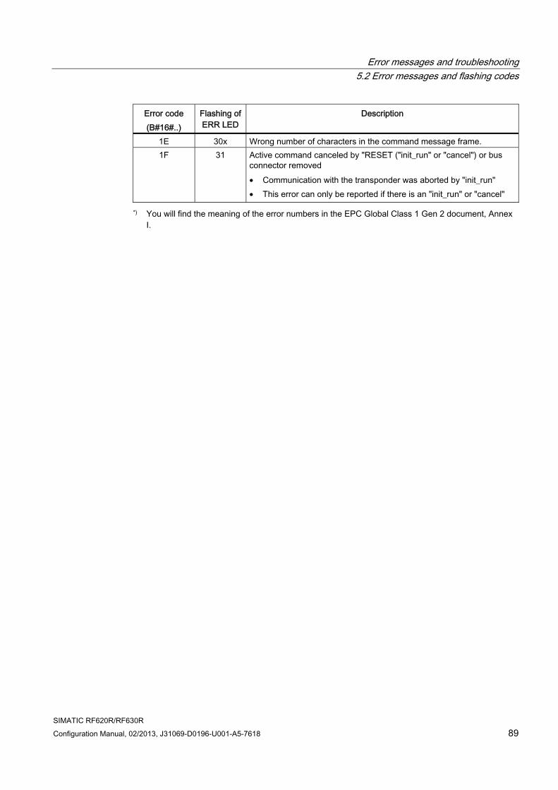
Error messages and troubleshooting 5.2 Error messages and flashing codes
SIMATIC RF620R/RF630R Configuration Manual, 02/2013, J31069-D0196-U001-A5-7618 89
Error code (B#16#..)
Flashing of ERR LED
Description
1E 30x Wrong number of characters in the command message frame. 1F 31 Active command canceled by "RESET ("init_run" or "cancel") or bus
connector removed • Communication with the transponder was aborted by "init_run" • This error can only be reported if there is an "init_run" or "cancel"
*) You will find the meaning of the error numbers in the EPC Global Class 1 Gen 2 document, Annex I.
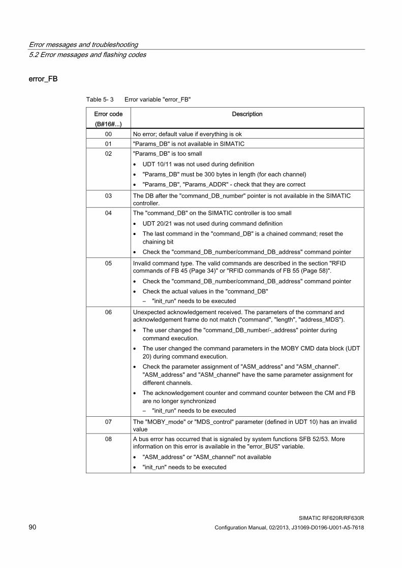
Error messages and troubleshooting 5.2 Error messages and flashing codes
SIMATIC RF620R/RF630R 90 Configuration Manual, 02/2013, J31069-D0196-U001-A5-7618
error_FB
Table 5- 3 Error variable "error_FB"
Error code (B#16#...)
Description
00 No error; default value if everything is ok 01 "Params_DB" is not available in SIMATIC 02 "Params_DB" is too small
• UDT 10/11 was not used during definition • "Params_DB" must be 300 bytes in length (for each channel) • "Params_DB", "Params_ADDR" - check that they are correct
03 The DB after the "command_DB_number" pointer is not available in the SIMATIC controller.
04 The "command_DB" on the SIMATIC controller is too small • UDT 20/21 was not used during command definition • The last command in the "command_DB" is a chained command; reset the
chaining bit • Check the "command_DB_number/command_DB_address" command pointer
05 Invalid command type. The valid commands are described in the section "RFID commands of FB 45 (Page 34)" or "RFID commands of FB 55 (Page 58)". • Check the "command_DB_number/command_DB_address" command pointer • Check the actual values in the "command_DB"
– "init_run" needs to be executed
06 Unexpected acknowledgement received. The parameters of the command and acknowledgement frame do not match ("command", "length", "address_MDS"). • The user changed the "command_DB_number/-_address" pointer during
command execution. • The user changed the command parameters in the MOBY CMD data block (UDT
20) during command execution. • Check the parameter assignment of "ASM_address" and "ASM_channel".
"ASM_address" and "ASM_channel" have the same parameter assignment for different channels.
• The acknowledgement counter and command counter between the CM and FB are no longer synchronized – "init_run" needs to be executed
07 The "MOBY_mode" or "MDS_control" parameter (defined in UDT 10) has an invalid value
08 A bus error has occurred that is signaled by system functions SFB 52/53. More information on this error is available in the "error_BUS" variable. • "ASM_address" or "ASM_channel" not available • "init_run" needs to be executed
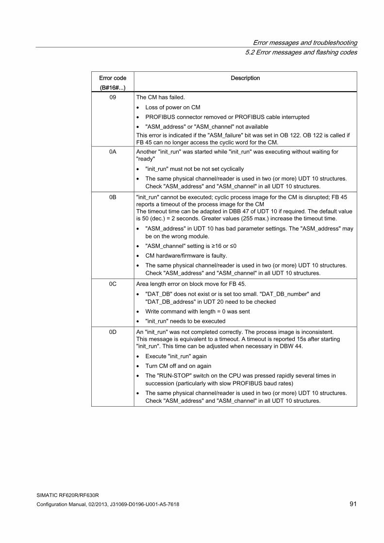
Error messages and troubleshooting 5.2 Error messages and flashing codes
SIMATIC RF620R/RF630R Configuration Manual, 02/2013, J31069-D0196-U001-A5-7618 91
Error code (B#16#...)
Description
09 The CM has failed. • Loss of power on CM • PROFIBUS connector removed or PROFIBUS cable interrupted • "ASM_address" or "ASM_channel" not available This error is indicated if the "ASM_failure" bit was set in OB 122. OB 122 is called if FB 45 can no longer access the cyclic word for the CM.
0A Another "init_run" was started while "init_run" was executing without waiting for "ready" • "init_run" must not be not set cyclically • The same physical channel/reader is used in two (or more) UDT 10 structures.
Check "ASM_address" and "ASM_channel" in all UDT 10 structures.
0B "init_run" cannot be executed; cyclic process image for the CM is disrupted; FB 45 reports a timeout of the process image for the CM The timeout time can be adapted in DBB 47 of UDT 10 if required. The default value is 50 (dec.) = 2 seconds. Greater values (255 max.) increase the timeout time. • "ASM_address" in UDT 10 has bad parameter settings. The "ASM_address" may
be on the wrong module. • "ASM_channel" setting is ≥16 or ≤0 • CM hardware/firmware is faulty. • The same physical channel/reader is used in two (or more) UDT 10 structures.
Check "ASM_address" and "ASM_channel" in all UDT 10 structures.
0C Area length error on block move for FB 45. • "DAT_DB" does not exist or is set too small. "DAT_DB_number" and
"DAT_DB_address" in UDT 20 need to be checked • Write command with length = 0 was sent • "init_run" needs to be executed
0D An "init_run" was not completed correctly. The process image is inconsistent. This message is equivalent to a timeout. A timeout is reported 15s after starting "init_run". This time can be adjusted when necessary in DBW 44. • Execute "init_run" again • Turn CM off and on again • The "RUN-STOP" switch on the CPU was pressed rapidly several times in
succession (particularly with slow PROFIBUS baud rates) • The same physical channel/reader is used in two (or more) UDT 10 structures.
Check "ASM_address" and "ASM_channel" in all UDT 10 structures.
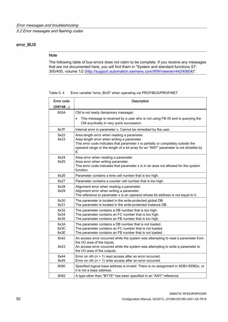
Error messages and troubleshooting 5.2 Error messages and flashing codes
SIMATIC RF620R/RF630R 92 Configuration Manual, 02/2013, J31069-D0196-U001-A5-7618
error_BUS
Note
The following table of bus errors does not claim to be complete. If you receive any messages that are not documented here, you will find them in "System and standard functions S7-300/400, volume 1/2 (http://support.automation.siemens.com/WW/view/en/44240604)".
Table 5- 4 Error variable "error_BUS" when operating via PROFIBUS/PROFINET
Error code (W#16#...)
Description
800A CM is not ready (temporary message) • This message is received by a user who is not using FB 45 and is querying the
CM acyclically in very quick succession.
8x7F Internal error in parameter x. Cannot be remedied by the user. 8x22 8x23
Area length error when reading a parameter. Area length error when writing a parameter. This error code indicates that parameter x is partially or completely outside the operand range or the length of a bit array for an "ANY" parameter is not divisible by 8.
8x24 8x25
Area error when reading a parameter. Area error when writing parameter. This error code indicates that parameter x is in an area not allowed for the system function.
8x26 Parameter contains a time cell number that is too high. 8x27 Parameter contains a counter cell number that is too high. 8x28 8x29
Alignment error when reading a parameter. Alignment error when writing a parameter. The reference to parameter x is an operand whose bit address is not equal to 0.
8x30 8x31
The parameter is located in the write-protected global DB. The parameter is located in the write-protected instance DB.
8x32 8x34 8x35
The parameter contains a DB number that is too high. The parameter contains an FC number that is too high. The parameter contains an FB number that is too high.
8x3A 8x3C 8x3E
The parameter contains a DB number that is not loaded. The parameter contains an FC number that is not loaded. The parameter contains an FB number that is not loaded.
8x42
8x43
An access error occurred while the system was attempting to read a parameter from the I/O area of the inputs. An access error occurred while the system was attempting to write a parameter to the I/O area of the outputs.
8x44 8x45
Error on nth (n > 1) read access after an error occurred. Error on nth (n > 1) write access after an error occurred.
8090 Specified logical base address is invalid: There is no assignment in SDB1/SDB2x, or it is not a base address.
8092 A type other than "BYTE" has been specified in an "ANY" reference.
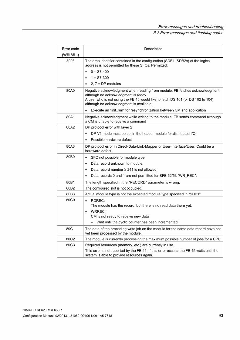
Error messages and troubleshooting 5.2 Error messages and flashing codes
SIMATIC RF620R/RF630R Configuration Manual, 02/2013, J31069-D0196-U001-A5-7618 93
Error code (W#16#...)
Description
8093 The area identifier contained in the configuration (SDB1, SDB2x) of the logical address is not permitted for these SFCs. Permitted: • 0 = S7-400 • 1 = S7-300 • 2, 7 = DP modules
80A0 Negative acknowledgment when reading from module; FB fetches acknowledgment although no acknowledgment is ready. A user who is not using the FB 45 would like to fetch DS 101 (or DS 102 to 104) although no acknowledgment is available. • Execute an "init_run" for resynchronization between CM and application
80A1 Negative acknowledgment while writing to the module. FB sends command although a CM is unable to receive a command
80A2 DP protocol error with layer 2 • DP-V1 mode must be set in the header module for distributed I/O. • Possible hardware defect
80A3 DP protocol error in Direct-Data-Link-Mapper or User-Interface/User. Could be a hardware defect.
80B0 • SFC not possible for module type. • Data record unknown to module. • Data record number ≥ 241 is not allowed. • Data records 0 and 1 are not permitted for SFB 52/53 "WR_REC".
80B1 The length specified in the "RECORD" parameter is wrong. 80B2 The configured slot is not occupied. 80B3 Actual module type is not the expected module type specified in "SDB1" 80C0 • RDREC:
The module has the record, but there is no read data there yet. • WRREC:
CM is not ready to receive new data – Wait until the cyclic counter has been incremented
80C1 The data of the preceding write job on the module for the same data record have not yet been processed by the module.
80C2 The module is currently processing the maximum possible number of jobs for a CPU.80C3 Required resources (memory, etc.) are currently in use.
This error is not reported by the FB 45. If this error occurs, the FB 45 waits until the system is able to provide resources again.
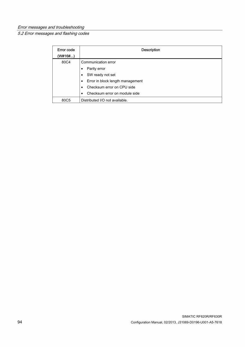
Error messages and troubleshooting 5.2 Error messages and flashing codes
SIMATIC RF620R/RF630R 94 Configuration Manual, 02/2013, J31069-D0196-U001-A5-7618
Error code (W#16#...)
Description
80C4 Communication error • Parity error • SW ready not set • Error in block length management • Checksum error on CPU side • Checksum error on module side
80C5 Distributed I/O not available.
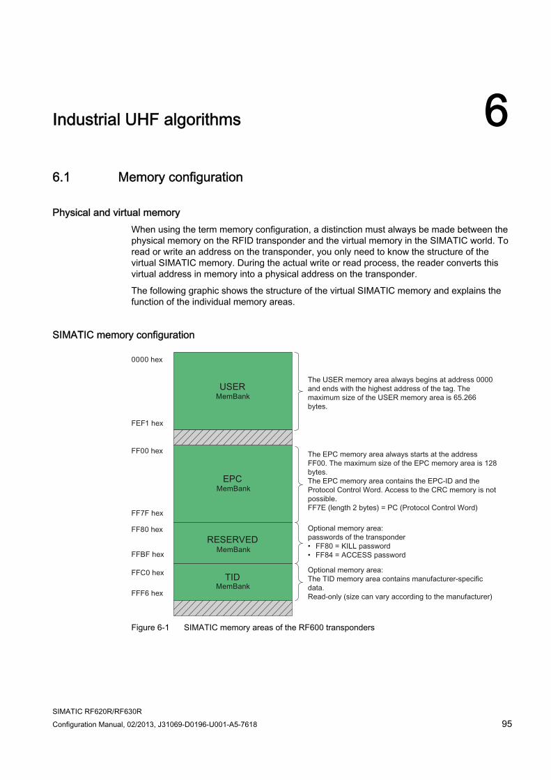
SIMATIC RF620R/RF630R Configuration Manual, 02/2013, J31069-D0196-U001-A5-7618 95
Industrial UHF algorithms 66.1 Memory configuration
Physical and virtual memory When using the term memory configuration, a distinction must always be made between the physical memory on the RFID transponder and the virtual memory in the SIMATIC world. To read or write an address on the transponder, you only need to know the structure of the virtual SIMATIC memory. During the actual write or read process, the reader converts this virtual address in memory into a physical address on the transponder.
The following graphic shows the structure of the virtual SIMATIC memory and explains the function of the individual memory areas.
SIMATIC memory configuration
Figure 6-1 SIMATIC memory areas of the RF600 transponders
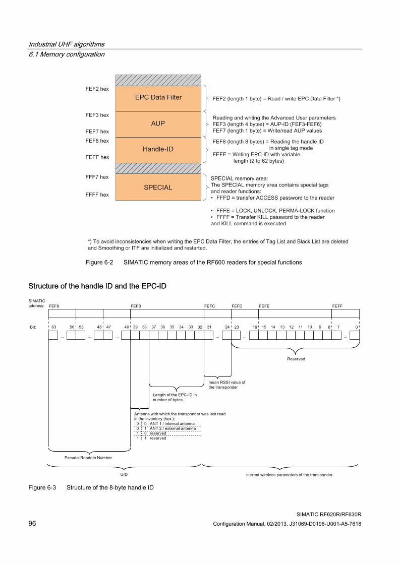
Industrial UHF algorithms 6.1 Memory configuration
SIMATIC RF620R/RF630R 96 Configuration Manual, 02/2013, J31069-D0196-U001-A5-7618
Figure 6-2 SIMATIC memory areas of the RF600 readers for special functions
Structure of the handle ID and the EPC-ID
Figure 6-3 Structure of the 8-byte handle ID
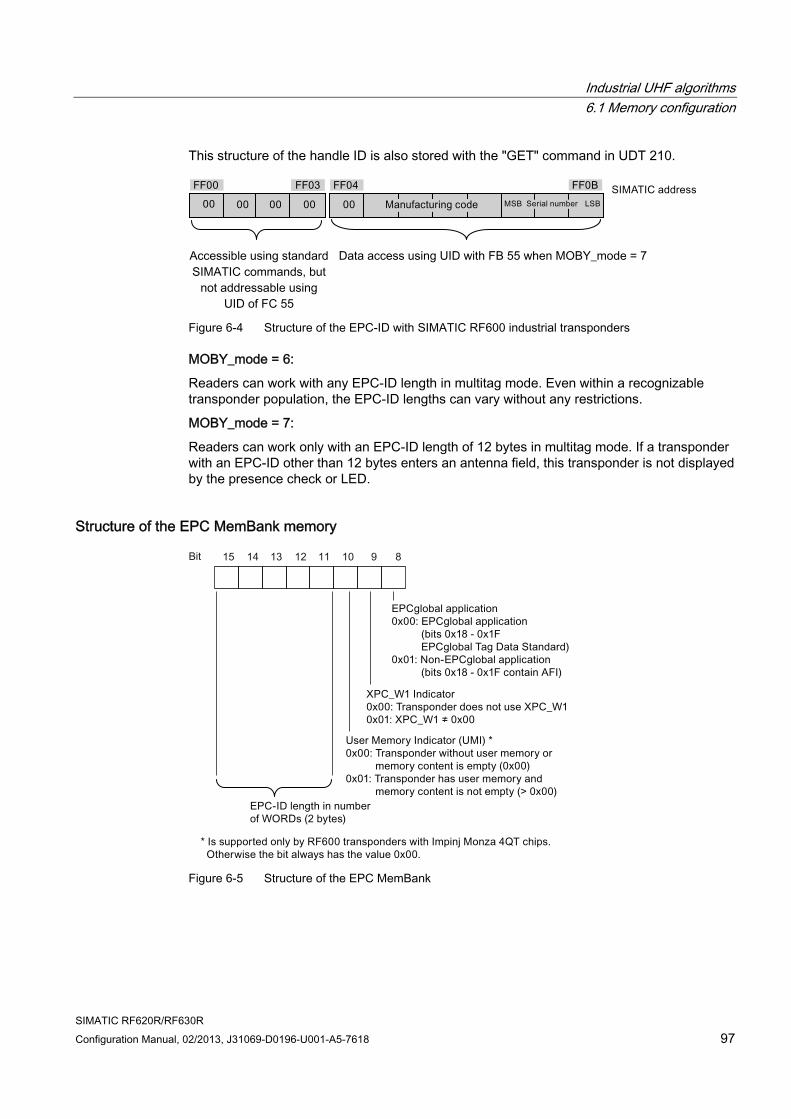
Industrial UHF algorithms 6.1 Memory configuration
SIMATIC RF620R/RF630R Configuration Manual, 02/2013, J31069-D0196-U001-A5-7618 97
This structure of the handle ID is also stored with the "GET" command in UDT 210.
Accessible using standard SIMATIC commands, but
not addressable using UID of FC 55
Data access using UID with FB 55 when MOBY_mode = 7
Figure 6-4 Structure of the EPC-ID with SIMATIC RF600 industrial transponders
MOBY_mode = 6:
Readers can work with any EPC-ID length in multitag mode. Even within a recognizable transponder population, the EPC-ID lengths can vary without any restrictions.
MOBY_mode = 7:
Readers can work only with an EPC-ID length of 12 bytes in multitag mode. If a transponder with an EPC-ID other than 12 bytes enters an antenna field, this transponder is not displayed by the presence check or LED.
Structure of the EPC MemBank memory
Figure 6-5 Structure of the EPC MemBank
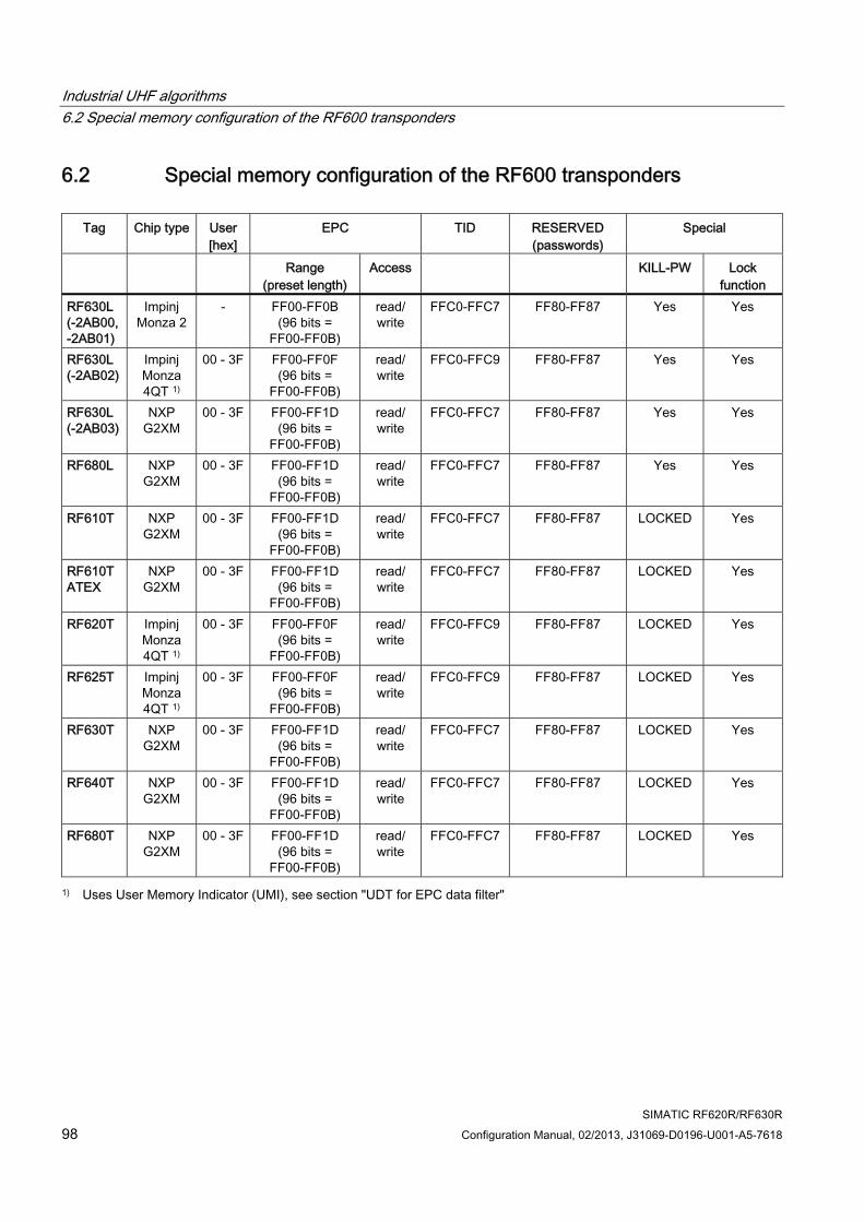
Industrial UHF algorithms 6.2 Special memory configuration of the RF600 transponders
SIMATIC RF620R/RF630R 98 Configuration Manual, 02/2013, J31069-D0196-U001-A5-7618
6.2 Special memory configuration of the RF600 transponders
Tag Chip type User [hex]
EPC TID RESERVED (passwords)
Special
Range (preset length)
Access KILL-PW Lock function
RF630L (-2AB00, -2AB01)
Impinj Monza 2
- FF00-FF0B (96 bits =
FF00-FF0B)
read/ write
FFC0-FFC7 FF80-FF87 Yes Yes
RF630L (-2AB02)
Impinj Monza 4QT 1)
00 - 3F FF00-FF0F (96 bits =
FF00-FF0B)
read/ write
FFC0-FFC9 FF80-FF87 Yes Yes
RF630L (-2AB03)
NXP G2XM
00 - 3F FF00-FF1D (96 bits =
FF00-FF0B)
read/ write
FFC0-FFC7 FF80-FF87 Yes Yes
RF680L NXP G2XM
00 - 3F FF00-FF1D (96 bits =
FF00-FF0B)
read/ write
FFC0-FFC7 FF80-FF87 Yes Yes
RF610T NXP G2XM
00 - 3F FF00-FF1D (96 bits =
FF00-FF0B)
read/ write
FFC0-FFC7 FF80-FF87 LOCKED Yes
RF610T ATEX
NXP G2XM
00 - 3F FF00-FF1D (96 bits =
FF00-FF0B)
read/ write
FFC0-FFC7 FF80-FF87 LOCKED Yes
RF620T Impinj Monza 4QT 1)
00 - 3F FF00-FF0F (96 bits =
FF00-FF0B)
read/ write
FFC0-FFC9 FF80-FF87 LOCKED Yes
RF625T Impinj Monza 4QT 1)
00 - 3F FF00-FF0F (96 bits =
FF00-FF0B)
read/ write
FFC0-FFC9 FF80-FF87 LOCKED Yes
RF630T NXP G2XM
00 - 3F FF00-FF1D (96 bits =
FF00-FF0B)
read/ write
FFC0-FFC7 FF80-FF87 LOCKED Yes
RF640T NXP G2XM
00 - 3F FF00-FF1D (96 bits =
FF00-FF0B)
read/ write
FFC0-FFC7 FF80-FF87 LOCKED Yes
RF680T NXP G2XM
00 - 3F FF00-FF1D (96 bits =
FF00-FF0B)
read/ write
FFC0-FFC7 FF80-FF87 LOCKED Yes
1) Uses User Memory Indicator (UMI), see section "UDT for EPC data filter"
Industrial UHF algorithms 6.3 Use of industrial UHF algorithms
SIMATIC RF620R/RF630R Configuration Manual, 02/2013, J31069-D0196-U001-A5-7618 99
6.3 Use of industrial UHF algorithms An application-optimized selection of the existing industrial UHF algorithms along with antenna management serve to minimize potential mutual interference of the neighboring UHF RF600 readers in an industrial UHF environment.
The industrial UHF algorithms show a change in the response of the readers, especially if the number of channels is very limited and therefore the likelihood of mutual interference via the air interface is high.
Note Use of the UHF algorithms
The use of the algorithms described here is complex and can change the response of the reader significantly. You should therefore only use these when the environment or the application demands them.
6.3.1 Overview of industrial UHF algorithms The basic settings as described in the previous sections allow the use of the UHF readers in a standard electromagnetic environment in which, for example, few readers are being used and the metallic environment does not provoke any overshoot. The algorithms described here are used to introduce a degree of freedom so that they can be used as a preliminary filter for transponder access in physically difficult applications.
Note The reader does not report any transponders
The aim of the industrial UHF algorithms is to filter the read transponders. This means that not all the transponders detected as being present in the antenna field are reported by the reader.
Make sure that the parameters for the algorithms are assigned so that access to the transponders in the environment you have selected and in the arrangements you require can be performed efficiently!
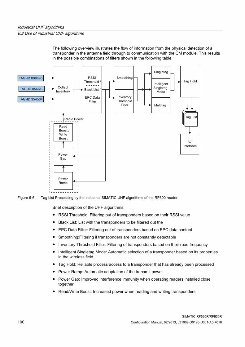
Industrial UHF algorithms 6.3 Use of industrial UHF algorithms
SIMATIC RF620R/RF630R 100 Configuration Manual, 02/2013, J31069-D0196-U001-A5-7618
The following overview illustrates the flow of information from the physical detection of a transponder in the antenna field through to communication with the CM module. This results in the possible combinations of filters shown in the following table.
Figure 6-6 Tag List Processing by the industrial SIMATIC UHF algorithms of the RF600 reader
Brief description of the UHF algorithms:
● RSSI Threshold: Filtering out of transponders based on their RSSI value
● Black List: List with the transponders to be filtered out the
● EPC Data Filter: Filtering out of transponders based on EPC data content
● Smoothing:Filtering if transponders are not constantly detectable
● Inventory Threshold Filter: Filtering of transponders based on their read frequency
● Intelligent Singletag Mode: Automatic selection of a transponder based on its properties in the wireless field
● Tag Hold: Reliable process access to a transponder that has already been processed
● Power Ramp: Automatic adaptation of the transmit power
● Power Gap: Improved interference immunity when operating readers installed close together
● Read/Write Boost: Increased power when reading and writing transponders
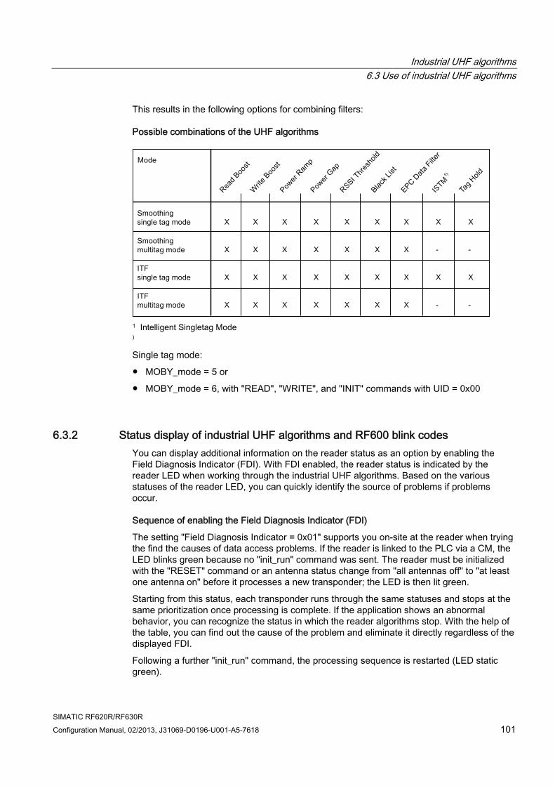
Industrial UHF algorithms 6.3 Use of industrial UHF algorithms
SIMATIC RF620R/RF630R Configuration Manual, 02/2013, J31069-D0196-U001-A5-7618 101
This results in the following options for combining filters:
Possible combinations of the UHF algorithms
1
) Intelligent Singletag Mode
Single tag mode:
● MOBY_mode = 5 or
● MOBY_mode = 6, with "READ", "WRITE", and "INIT" commands with UID = 0x00
6.3.2 Status display of industrial UHF algorithms and RF600 blink codes You can display additional information on the reader status as an option by enabling the Field Diagnosis Indicator (FDI). With FDI enabled, the reader status is indicated by the reader LED when working through the industrial UHF algorithms. Based on the various statuses of the reader LED, you can quickly identify the source of problems if problems occur.
Sequence of enabling the Field Diagnosis Indicator (FDI)
The setting "Field Diagnosis Indicator = 0x01" supports you on-site at the reader when trying the find the causes of data access problems. If the reader is linked to the PLC via a CM, the LED blinks green because no "init_run" command was sent. The reader must be initialized with the "RESET" command or an antenna status change from "all antennas off" to "at least one antenna on" before it processes a new transponder; the LED is then lit green.
Starting from this status, each transponder runs through the same statuses and stops at the same prioritization once processing is complete. If the application shows an abnormal behavior, you can recognize the status in which the reader algorithms stop. With the help of the table, you can find out the cause of the problem and eliminate it directly regardless of the displayed FDI.
Following a further "init_run" command, the processing sequence is restarted (LED static green).
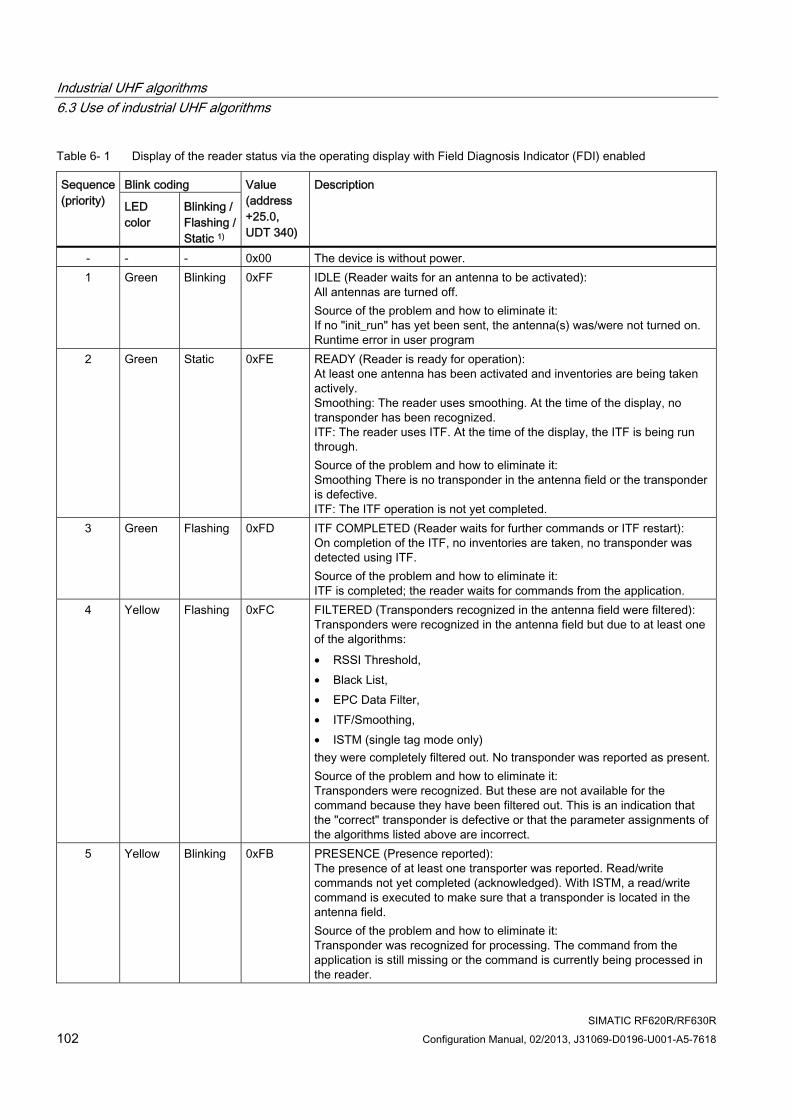
Industrial UHF algorithms 6.3 Use of industrial UHF algorithms
SIMATIC RF620R/RF630R 102 Configuration Manual, 02/2013, J31069-D0196-U001-A5-7618
Table 6- 1 Display of the reader status via the operating display with Field Diagnosis Indicator (FDI) enabled
Blink coding Sequence (priority) LED
color Blinking / Flashing / Static 1)
Value (address +25.0, UDT 340)
Description
- - - 0x00 The device is without power. 1 Green Blinking 0xFF IDLE (Reader waits for an antenna to be activated):
All antennas are turned off. Source of the problem and how to eliminate it: If no "init_run" has yet been sent, the antenna(s) was/were not turned on. Runtime error in user program
2 Green Static 0xFE READY (Reader is ready for operation): At least one antenna has been activated and inventories are being taken actively. Smoothing: The reader uses smoothing. At the time of the display, no transponder has been recognized. ITF: The reader uses ITF. At the time of the display, the ITF is being run through. Source of the problem and how to eliminate it: Smoothing There is no transponder in the antenna field or the transponder is defective. ITF: The ITF operation is not yet completed.
3 Green Flashing 0xFD ITF COMPLETED (Reader waits for further commands or ITF restart): On completion of the ITF, no inventories are taken, no transponder was detected using ITF. Source of the problem and how to eliminate it: ITF is completed; the reader waits for commands from the application.
4 Yellow Flashing 0xFC FILTERED (Transponders recognized in the antenna field were filtered): Transponders were recognized in the antenna field but due to at least one of the algorithms: • RSSI Threshold, • Black List, • EPC Data Filter, • ITF/Smoothing, • ISTM (single tag mode only) they were completely filtered out. No transponder was reported as present.Source of the problem and how to eliminate it: Transponders were recognized. But these are not available for the command because they have been filtered out. This is an indication that the "correct" transponder is defective or that the parameter assignments of the algorithms listed above are incorrect.
5 Yellow Blinking 0xFB PRESENCE (Presence reported): The presence of at least one transporter was reported. Read/write commands not yet completed (acknowledged). With ISTM, a read/write command is executed to make sure that a transponder is located in the antenna field. Source of the problem and how to eliminate it: Transponder was recognized for processing. The command from the application is still missing or the command is currently being processed in the reader.
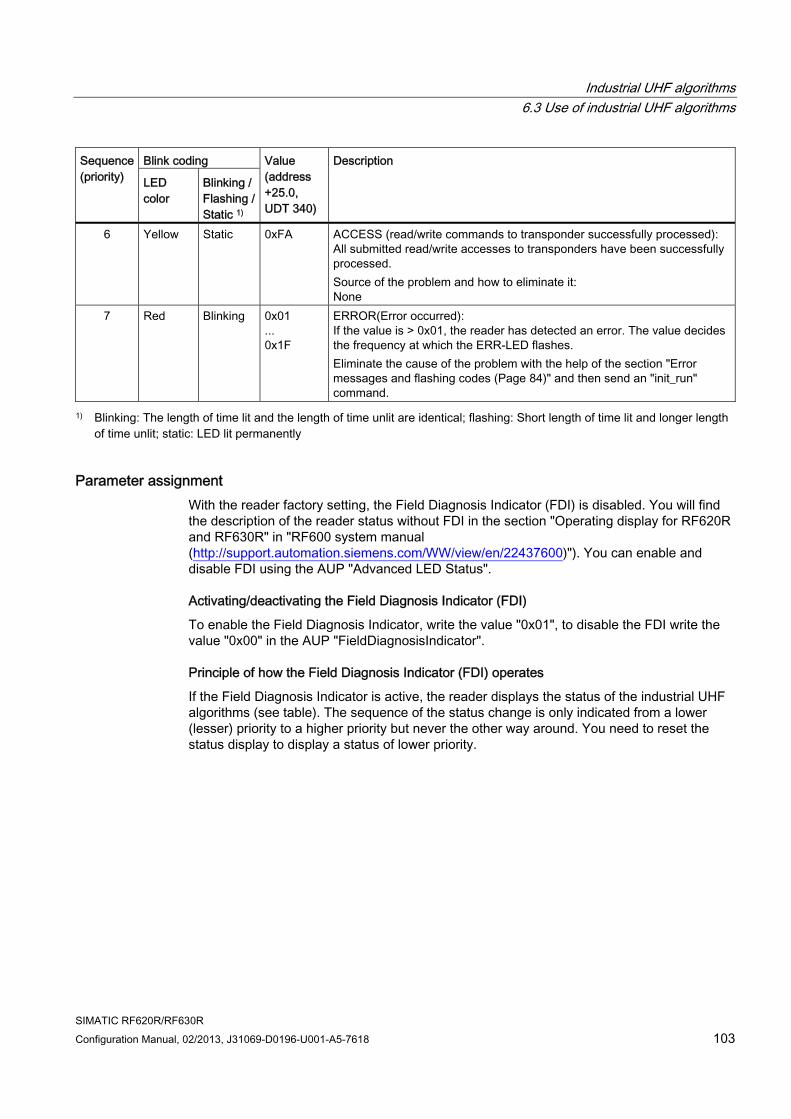
Industrial UHF algorithms 6.3 Use of industrial UHF algorithms
SIMATIC RF620R/RF630R Configuration Manual, 02/2013, J31069-D0196-U001-A5-7618 103
Blink coding Sequence (priority) LED
color Blinking / Flashing / Static 1)
Value (address +25.0, UDT 340)
Description
6 Yellow Static 0xFA ACCESS (read/write commands to transponder successfully processed): All submitted read/write accesses to transponders have been successfully processed. Source of the problem and how to eliminate it: None
7 Red Blinking 0x01 ... 0x1F
ERROR(Error occurred): If the value is > 0x01, the reader has detected an error. The value decides the frequency at which the ERR-LED flashes. Eliminate the cause of the problem with the help of the section "Error messages and flashing codes (Page 84)" and then send an "init_run" command.
1) Blinking: The length of time lit and the length of time unlit are identical; flashing: Short length of time lit and longer length of time unlit; static: LED lit permanently
Parameter assignment With the reader factory setting, the Field Diagnosis Indicator (FDI) is disabled. You will find the description of the reader status without FDI in the section "Operating display for RF620R and RF630R" in "RF600 system manual (http://support.automation.siemens.com/WW/view/en/22437600)"). You can enable and disable FDI using the AUP "Advanced LED Status".
Activating/deactivating the Field Diagnosis Indicator (FDI)
To enable the Field Diagnosis Indicator, write the value "0x01", to disable the FDI write the value "0x00" in the AUP "FieldDiagnosisIndicator".
Principle of how the Field Diagnosis Indicator (FDI) operates
If the Field Diagnosis Indicator is active, the reader displays the status of the industrial UHF algorithms (see table). The sequence of the status change is only indicated from a lower (lesser) priority to a higher priority but never the other way around. You need to reset the status display to display a status of lower priority.
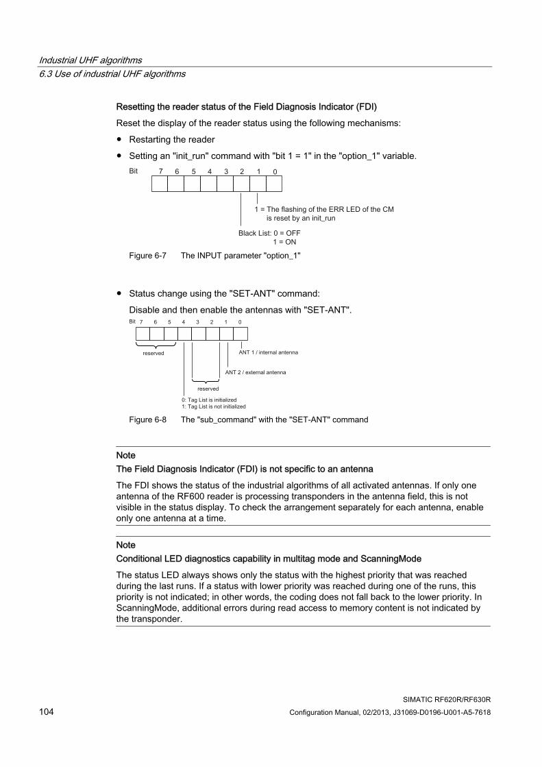
Industrial UHF algorithms 6.3 Use of industrial UHF algorithms
SIMATIC RF620R/RF630R 104 Configuration Manual, 02/2013, J31069-D0196-U001-A5-7618
Resetting the reader status of the Field Diagnosis Indicator (FDI)
Reset the display of the reader status using the following mechanisms:
● Restarting the reader
● Setting an "init_run" command with "bit 1 = 1" in the "option_1" variable.
Figure 6-7 The INPUT parameter "option_1"
● Status change using the "SET-ANT" command:
Disable and then enable the antennas with "SET-ANT".
Figure 6-8 The "sub_command" with the "SET-ANT" command
Note The Field Diagnosis Indicator (FDI) is not specific to an antenna
The FDI shows the status of the industrial algorithms of all activated antennas. If only one antenna of the RF600 reader is processing transponders in the antenna field, this is not visible in the status display. To check the arrangement separately for each antenna, enable only one antenna at a time.
Note Conditional LED diagnostics capability in multitag mode and ScanningMode
The status LED always shows only the status with the highest priority that was reached during the last runs. If a status with lower priority was reached during one of the runs, this priority is not indicated; in other words, the coding does not fall back to the lower priority. In ScanningMode, additional errors during read access to memory content is not indicated by the transponder.
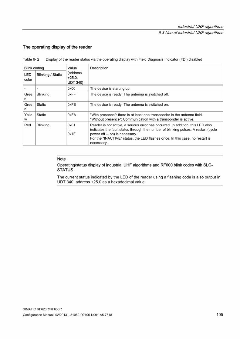
Industrial UHF algorithms 6.3 Use of industrial UHF algorithms
SIMATIC RF620R/RF630R Configuration Manual, 02/2013, J31069-D0196-U001-A5-7618 105
The operating display of the reader
Table 6- 2 Display of the reader status via the operating display with Field Diagnosis Indicator (FDI) disabled
Blink coding
LED color
Blinking / Static
Value (address +25.0, UDT 340)
Description
- - 0x00 The device is starting up. Green
Blinking 0xFF The device is ready. The antenna is switched off.
Green
Static 0xFE The device is ready. The antenna is switched on.
Yellow
Static 0xFA "With presence": there is at least one transponder in the antenna field. "Without presence": Communication with a transponder is active.
Red Blinking 0x01 ... 0x1F
Reader is not active, a serious error has occurred. In addition, this LED also indicates the fault status through the number of blinking pulses. A restart (cycle power off → on) is necessary. For the "INACTIVE" status, the LED flashes once. In this case, no restart is necessary.
Note Operating/status display of industrial UHF algorithms and RF600 blink codes with SLG-STATUS
The current status indicated by the LED of the reader using a flashing code is also output in UDT 340, address +25.0 as a hexadecimal value.
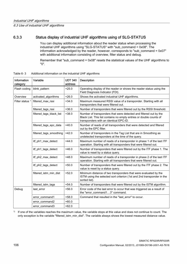
Industrial UHF algorithms 6.3 Use of industrial UHF algorithms
SIMATIC RF620R/RF630R 106 Configuration Manual, 02/2013, J31069-D0196-U001-A5-7618
6.3.3 Status display of industrial UHF algorithms using of SLG-STATUS You can display additional information about the reader status when processing the industrial UHF algorithms using "SLG-STATUS" with "sub_command = 0x08". The information acknowledged by the reader, however, corresponds to "sub_command = 0x07" with additional information consisting of overview, filter status and debug.
Remember that "sub_command = 0x08" resets the statistical values of the UHF algorithms to "0".
Table 6- 3 Additional information on the industrial UHF algorithms
Information category
Variable UDT 340 address
Description
Flash coding blink_pattern +25.0 Operating display of the reader or shows the reader status using the Field Diagnosis Indicator (FDI).
Overview activated_algorithms +26.0 Shows the activated industrial UHF algorithms. filtered_max_rssi +34.0 Maximum measured RSSI value of a transponder. Starting with all
transponders that were filtered out. filtered_tags_rssi +36.0 Number of transponders that were filtered out by the RSSI threshold. filtered_tags_black_list +38.0 Number of transponders that were detected and filtered out by the
Black List. This list contains no empty entries or double counts of transponders with an identical EPC-ID.
filtered_tags_epc_data +40.0 Number of reads of all transponders that were detected and filtered out by the EPC filter.
filtered_tags_smoothing +42.0 Number of transponders in the Tag List that are in Smoothing as undetected transponders at the time of the query.
itf_ph1_max_detect +44.0 Maximum number of reads of a transponder in phase 1 of the last ITF operation. Starting with all transponders that were filtered out.
itf_ph1_tags_detect +46.0 Number of transponders that were filtered out by the ITF phase 1. The value is reset by a status query.
itf_ph2_max_detect +48.0 Maximum number of reads of a transponder in phase 2 of the last ITF operation. Starting with all transponders that were filtered out.
itf_ph2_tags_detect +50.0 Number of transponders that were filtered out by the ITF phase 2. The value is reset by a status query.
filtered_istm_min_dist +52.0 Minimum distance of two transponders that were evaluated by the ISTM using the selected sort criterion (1st and 2nd transponder in the sorted list).
Filter status 1
filtered_istm_tags +54.0 Number of transponders that were filtered out by the ISTM algorithm. last_error +56.0 Error code of the last error to occur that was triggered as a result of
the "error_command1…3" command. error_command1 +58.0 error_command2 +60.0
Debug
error_command3 +62.0
Command that resulted in the "last_error" to occur.
1) If one of the variables reaches the maximum value, the variable stops at this value and does not continue to count. The only exception is the variable "filtered_istm_min_dist". The variable always shows the lowest measured distance value.
Industrial UHF algorithms 6.3 Use of industrial UHF algorithms
SIMATIC RF620R/RF630R Configuration Manual, 02/2013, J31069-D0196-U001-A5-7618 107
Parameter assignment
Starting and resetting the status display
To start data acquisition, you need to send an "init_run" command.
To reset the status display and restart, there are two mechanisms:
● Restarting the reader followed by sending a valid "init_run" command
● Sending the "SLG-STATUS" with "sub_command = 0x08"
Deactivating of the status display
Deactivation is not possible.
Sequence of the status display algorithm
After starting the algorithm, all bits are set to the "activated_algorithms" status. The "filtered_istm_min_dist" variable is written with an initial value "0xFFFF". The other variables are initialized with "0x00" or "0x0000".
Each variable is updated with every cycle of the individual filters and algorithms. By calling the "SLG-STATUS" with "sub_command = 0x08", the values valid at the time of the call are acknowledged and the variables are reinitialized.
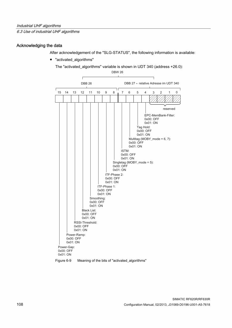
Industrial UHF algorithms 6.3 Use of industrial UHF algorithms
SIMATIC RF620R/RF630R 108 Configuration Manual, 02/2013, J31069-D0196-U001-A5-7618
Acknowledging the data After acknowledgement of the "SLG-STATUS", the following information is available:
● "activated_algorithms"
The "activated_algorithms" variable is shown in UDT 340 (address +26.0):
Figure 6-9 Meaning of the bits of "activated_algorithms"
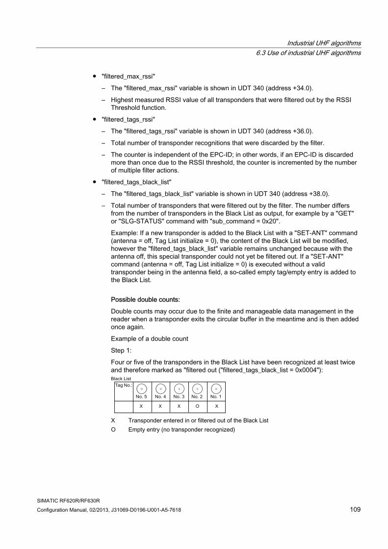
Industrial UHF algorithms 6.3 Use of industrial UHF algorithms
SIMATIC RF620R/RF630R Configuration Manual, 02/2013, J31069-D0196-U001-A5-7618 109
● "filtered_max_rssi"
– The "filtered_max_rssi" variable is shown in UDT 340 (address +34.0).
– Highest measured RSSI value of all transponders that were filtered out by the RSSI Threshold function.
● "filtered_tags_rssi"
– The "filtered_tags_rssi" variable is shown in UDT 340 (address +36.0).
– Total number of transponder recognitions that were discarded by the filter.
– The counter is independent of the EPC-ID; in other words, if an EPC-ID is discarded more than once due to the RSSI threshold, the counter is incremented by the number of multiple filter actions.
● "filtered_tags_black_list"
– The "filtered_tags_black_list" variable is shown in UDT 340 (address +38.0).
– Total number of transponders that were filtered out by the filter. The number differs from the number of transponders in the Black List as output, for example by a "GET" or "SLG-STATUS" command with "sub_command = 0x20".
Example: If a new transponder is added to the Black List with a "SET-ANT" command (antenna = off, Tag List initialize = 0), the content of the Black List will be modified, however the "filtered_tags_black_list" variable remains unchanged because with the antenna off, this special transponder could not yet be filtered out. If a "SET-ANT" command (antenna = off, Tag List initialize = 0) is executed without a valid transponder being in the antenna field, a so-called empty tag/empty entry is added to the Black List.
Possible double counts:
Double counts may occur due to the finite and manageable data management in the reader when a transponder exits the circular buffer in the meantime and is then added once again.
Example of a double count
Step 1:
Four or five of the transponders in the Black List have been recognized at least twice and therefore marked as "filtered out ("filtered_tags_black_list = 0x0004"):
X X O XX
X Transponder entered in or filtered out of the Black List O Empty entry (no transponder recognized)
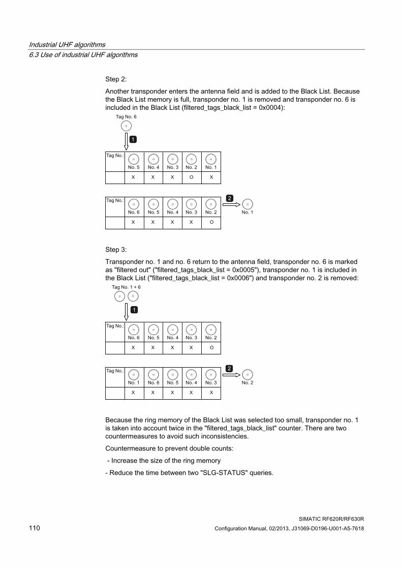
Industrial UHF algorithms 6.3 Use of industrial UHF algorithms
SIMATIC RF620R/RF630R 110 Configuration Manual, 02/2013, J31069-D0196-U001-A5-7618
Step 2:
Another transponder enters the antenna field and is added to the Black List. Because the Black List memory is full, transponder no. 1 is removed and transponder no. 6 is included in the Black List (filtered_tags_black_list = 0x0004):
X X O XX
X X X OX
Step 3:
Transponder no. 1 and no. 6 return to the antenna field, transponder no. 6 is marked as "filtered out" ("filtered_tags_black_list = 0x0005"), transponder no. 1 is included in the Black List ("filtered_tags_black_list = 0x0006") and transponder no. 2 is removed:
X X X OX
X X X XX
Because the ring memory of the Black List was selected too small, transponder no. 1 is taken into account twice in the "filtered_tags_black_list" counter. There are two countermeasures to avoid such inconsistencies.
Countermeasure to prevent double counts:
- Increase the size of the ring memory
- Reduce the time between two "SLG-STATUS" queries.
Industrial UHF algorithms 6.3 Use of industrial UHF algorithms
SIMATIC RF620R/RF630R Configuration Manual, 02/2013, J31069-D0196-U001-A5-7618 111
● "filtered_tags_epc_data"
– The "filtered_tags_epc_data" variable is shown in UDT 340 (address +38.0).
– Total number of filter actions with which transponders were filtered out using the EPC Data Filter at the time of the "SLG-STATUS" query.
Note Displays the number of transponders filtered out
If "x" different transponders were filtered out "y" times consecutively, the number " x * y" is displayed by "filtered_tags_epc_data".
Example: If 5 transponders are filtered out 10 times, the value "500" (0x01F4) is displayed.
● "filtered_tags_smoothing"
– The "filtered_tags_smoothing" variable is shown in UDT 340 (address +40.0).
– Total number of transponders that were filtered out at the time or "SLG-STATUS" by Smoothing.
Note Status display with "filtered_tags_smoothing"
The "filtered_tags_smoothing" variable returns the current status of the Tag List. The variable does not display the total number of transponders between two "SLG-STATUS" queries that were filtered out by Smoothing.
● "itf_ph1_max_detect"
– The "itf_ph1_max_detect" variable is shown in UDT 340 (address +42.0).
– The maximum number of reads of a transponder in phase 1. Starting with all the transponders that were filtered out by the ITF in phase 1.
– Quantitative measure for the selection of "ITF_Histogramm_Phase1". The greater the distance between "itf_ph1_max_detect" and "ITF_Histogramm_Phase1" and if only the selected transponder is processed further, the more reliable the detection of the transponder using ITF.
– If the ITF is run more than once, you always receive the maximum number of reads of the transponder that was read most often in one of the runs. This transponder, however, has not reached the minimum number of transponder recognitions and was filtered out.
● "itf_ph1_tags_detect"
– The "itf_ph1_tags_detect" variable is shown in UDT 340 (address +44.0).
– Total number of transponder recognitions discarded by the ITF in phase 1.
– If the ITF is run through more than once, the total number of transponders that were filtered out in all the runs of the ITF in phase 1 is displayed.
Industrial UHF algorithms 6.3 Use of industrial UHF algorithms
SIMATIC RF620R/RF630R 112 Configuration Manual, 02/2013, J31069-D0196-U001-A5-7618
● "itf_ph2_max_detect“
– The "itf_ph2_max_detect" variable is shown in UDT 340 (address +46.0).
– The maximum number of reads of a transponder in phase 2. Starting with all the transponders that were filtered out by the ITF in phase 2.
– Quantitative measure for the selection of "ITF_Histogramm_Phase2". The greater the distance between "itf_ph2_max_detect" and "ITF_Histogramm_Phase2" and if only the selected transponder is processed further, the more reliable the detection of the transponder using ITF.
– If the ITF is run more than once, you always receive the maximum number of reads of the transponder that was read most often in one of the runs. This transponder, however, has not reached the minimum number of transponder recognitions and was filtered out.
● "itf_ph2_tags_detect"
– The "itf_ph2_tags_detect" variable is shown in UDT 340 (address +48.0).
– Total number of transponder recognitions discarded by the ITF in phase 2.
– If the ITF is run through more than once, the total number of transponders that were filtered out in all the runs of the ITF in phase 1 is displayed.
● "filtered_istm_min_dist"
– The "filtered_istm_min_dist" variable is shown in UDT 340 (address +50.0).
– Minimum distance of two transponders that were evaluated by the ISTM using the selected sort criterion (1st and 2nd transponder in the sorted list).
– The minimum distance always defines the worst-case scenario. If no valid transponder could be found with ISTM, the minimum distance is "0x0000". If a valid transponder was found using ISTM, the minimum distance is the threshold of the ISTM.
Industrial UHF algorithms 6.3 Use of industrial UHF algorithms
SIMATIC RF620R/RF630R Configuration Manual, 02/2013, J31069-D0196-U001-A5-7618 113
● "filtered_istm_tags"
– The "filtered_istm_tags" variable is shown in UDT 340 (address +52.0).
– Total number of transponder recognitions that were discarded by ISTM.
– If the ISTM is run through, the total number of transponders that were filtered out in all the runs of the ISTM in phase 1 is displayed.
Example of the ISTM statistics:
– With each run, the distance, from the point of view of the sorting criterion Sorting between the 1st and 2nd transponder is detected. The distance is updated if the distance between the first two transponders has become less than in all previous runs. The value determines the shortest distance that was ever reached between the first two transponders. As result, the distance can reach the minimum value "0x0000".
– When successful, in other words, when a transponder is reported as valid, the number of all discarded transponders is added up and the distance between the 1st and 2nd transponder is defined as "0xFFFF". This assumes that there was no 2nd transponder in the antenna field.
– With a run through of the ISTM, there are three possibilities:
a. One or no transponder was recognized:
- "filtered_istm_tags = 0x0000"
- "filtered_istm_min_dist = 0xFFFF"
b. "n" transponders were recognized, the distance criterion between the 1st and 2nd transponder was kept to:
- "filtered_istm_tags = n - 1";
- "filtered_istm_min_dist = 0xXXXX", where "0xXXXX" is the hexadecimal value for the distance between the 1st and 2nd transponder.
b. "n" transponders were recognized, the distance criterion between the 1st and 2nd transponder was not kept to:
- "filtered_istm_tags = n";
- "filtered_istm_min_dist = 0xXXXX", where "0xXXXX" is the hexadecimal value for the distance between the 1st and 2nd transponder.
● "last_error"
– Error code of the last error to occur that was triggered as a result of the "error_command1,...,error_command3" command.
– If no error has occurred, the data content of "last_error = 0x00"
● "error_command1,…,error_command3"
– Call for the command that resulted in the "last_error" to occur.
– If no error has occurred, the data content of "error_command1 = 0x0000,…,error_command3 = 0x0000"
– The first 3 WORD (2 bytes) of a command/command header are output. If the command is > 6 bytes, the remainder is truncated. If the command is < 6 bytes, the remainder is padded with "0x00".
Industrial UHF algorithms 6.3 Use of industrial UHF algorithms
SIMATIC RF620R/RF630R 114 Configuration Manual, 02/2013, J31069-D0196-U001-A5-7618
Note The statistics of all variables are corrupted in the filter status
Note that the following changes between two successful acknowledgements of "SLG-STATUS" with "sub_command = 0x08" can lead to the statistics being corrupted: • Reassigning parameters of the industrial UHF algorithms using the "RESET" command, • Enabling/disabling RSSI Threshold, Black List, EPC Data Filter or • Setting the AUPs.
6.3.4 Tag list The Tag List is a reader-internal list of transponders. Each transponder recognized as being valid by a reader is entered in the Tag List. The Tag List contains information about the transponders, for example handle IDs, EPC-IDs and RSSI values.
In MOBY_mode = 6, you can read out the Tag List with the "GET" command. With the "sub_command" parameter of the "GET" command, you can select various sorting criteria. As an example, the transponder with the highest average RSSI value can be transferred to the first position in the list. This means that you can specify access the transponder closest to the antenna.
Note Initialization of the Tag List
As soon as the "SET-ANT" command (with the "sub_command" bit 4 = 0) has been sent, the entries in the Tag List are discarded, the "ANZ_MDS_present" bit is set to 0.
With an "init_run" or a "SET-ANT" command (antenna ON) with bit 4 = 0, all entries in the Tag List are discarded and the Tag List is initialized. All the transponders in the antenna field are re-entered in the Tag List and the number of transponders is updated.
If bit 4 = 1 is set in the "SET-ANT" command of "sub_command", the Tag List is not discarded but continues to be updated. This also applies if the antennas are turned off. When using Smoothing, the reader makes further inventories internally. If the antenna is turned off, these inventories do not receive any transponders so that after 5 inventories, the transponder is removed from the Tag List.
Industrial UHF algorithms 6.3 Use of industrial UHF algorithms
SIMATIC RF620R/RF630R Configuration Manual, 02/2013, J31069-D0196-U001-A5-7618 115
6.3.5 Smoothing versus Inventory Threshold Filter (ITF)
Smoothing For standard applications, the reader uses the Smoothing algorithm.
During Smoothing, following an "init_run" command, the reader always takes inventories in the background while processing SIMATIC commands and with these inventories, it can analyze which transponders are in the antenna field when and how often. With the help of these inventories, the Smoothing algorithm can avoid disruptions.
A transponder counts as being recognized when it is detected often enough successively in the inventories that have been taken. The Smoothing criterion, the number of successive detections is defined by the "Observed Threshold Count" parameter.
If a transponder is not recognized for the number of successive inventories specified in "Observed Threshold Count", a transponder is discarded and declared as not present.
Data access using SIMATIC is only possible after a transponder has been marked as detected:
● Updating the presence
● Read/write access to the transponder
The smoothing algorithm is re-initialized and started after an "init_run" or "SET-ANT" command in which bit 4 = 0 is set in the "sub_command".
While the Smoothing is active, the Tag List is updated continuously.
Note Duration of pauses
When using Smoothing, remember to include a pause between "init_run" or "SET-ANT" and the "GET" command. This is the only way to make sure that the reader has adequate time to detect all transponders in the antenna fields.
Remember that the time of the pause is N times longer depending on the number of transponders in the antenna field. If "Observed Threshold Count" is active, the time of the pause increases again depending on the set value and the transponders located in the antenna field.
Industrial UHF algorithms 6.3 Use of industrial UHF algorithms
SIMATIC RF620R/RF630R 116 Configuration Manual, 02/2013, J31069-D0196-U001-A5-7618
Example
It is difficult to bring 2 or more transponders into an antenna field from the outside dynamically at the same time. In such a situation, typically only one single transponder is detected first. With Smoothing (a transponder must be detected 5x in succession), this means that this transponder is also the first to be recognized as valid.
The response described is a UHF system property.
● If, for example, 2 or more transponders are placed statically in front of the antenna and the sequence is started on the reader, the error "0x1D" - "more than one tag in the field" - is reported in single tag mode.
● If the sequence is started on the reader before there are transponders in the antenna field and if 2 or more transponders are then brought into the antenna field and left in an ideal position in front of the antenna, no "0x1D" error is reported because the first detected transponder is processed immediately.
This response can be avoided with the help of the ITF algorithm.
Inventory Threshold Filter (ITF) For applications in which transponder access can be critical due to the environment (overshoots, sporadic detection/non-detection of transponders etc.) The Inventory Threshold Filter is available.
Following an "init_run" command, the readers take a selectable number of inventories. On completion of the last inventory, the transponders detected with a selectable frequency are marked as being valid. Only then is the presence updated and read/write access to the transponders possible.
Remember that transponders are detected only while the ITF is running. After this, no further inventories are made until the ITF is restarted.
The ITF uses two phases that differ in their duration and Power Ramp functions.
Industrial UHF algorithms 6.3 Use of industrial UHF algorithms
SIMATIC RF620R/RF630R Configuration Manual, 02/2013, J31069-D0196-U001-A5-7618 117
● ITF phase 1:
The Power Ramp (Page 119) is used. If only one transponder was selected following phase 1, filtering is completed. The selected transponder is processed further and phase 2 is not run through. This also applies to the multitag mode. The ITF phase 1 is run through taking into account the parameter assignment of the ITF Duration Phase 1 and ITF Histogram Phase 1.
● ITF phase 2:
If no or more than one transponder was detected in phase 1, phase 2 is started. The parameter assignment for phase 2 is not dependent on phase 1. The Power Ramp for phase 2 differs from the normal Power Ramp:
1. A fixed number of inventories is defined that are executed with a constant antenna power. Following this, the power is increased by a selectable amount before the next fixed number of inventories is worked through.
2. The initial power of phase 2 is the same as the power currently set by phase 1.
3. All the transponders recognized as being valid at the end of phase 2 are processed further; in other words, phase 2 - in contrast to phase 1 - can also return more than one transponder.
Note Using the ITF
Use the ITF only when you can be sure that the transponders to be read are located in the antenna field within a defined time.
ITF parameter assignment
The ITF algorithm is stopped, re-initialized and started after an "init_run" or "SET-ANT" command in which bit 4 = 0 is set in the "sub_command".
The ITF algorithm is stopped if no antenna is active; in other words following an "init_run" command, a "SET-ANT" command is sent in which bits 0 and 1 = 0 in the "sub_command".
Group Name Note
Boost Step Size ANT 1
Increased power per step of the Power Rampof antenna 1 in 0.25 dB steps (e.g. 0x02 corresponds to 0.5 dB power increase in one step).
Boost Step Size ANT 2
Increased power per step of the Power Ramp of antenna 1 in 0.25 dB steps (e.g. 0x02 corresponds to 0.5 dB power increase in one step).
Boost Max ANT 1
Maximum power increase after N steps of the Power Ramp of antenna 1 in 0.25 dB steps. With the basic setting 0x00, the Power Ramp for antenna 1 is deactivated.
Boost Max ANT 2
Maximum power increase after N steps of the Power Ramp of antenna 1 in 0.25 dB steps. With the basic setting 0x00, the Power Ramp for antenna 2 is deactivated.
Power Ramp
Boost Threshold ANT 1
Number of consecutive inventories worked through via antenna 1 in which no transponder was detected before the power is increased. When the Inventory Threshold Filter is active, number of inventories taken consecutively via antenna 1 before the power is increased.
Industrial UHF algorithms 6.3 Use of industrial UHF algorithms
SIMATIC RF620R/RF630R 118 Configuration Manual, 02/2013, J31069-D0196-U001-A5-7618
Group Name Note Boost Threshold ANT 2
Number of consecutive inventories taken via antenna 2 in which no transponder was detected before the power is increased. When the Inventory Threshold Filter is active, number of inventories taken consecutively via antenna 2 before the power is increased.
Boost2 Step Size ANT 1
Increased power per step of the Power Ramp of antenna 1 in 0.25 dB steps (e.g. 0x02 corresponds to 0.5 dB power increase in one step).
Boost2 Step Size ANT2
Increased power per step of the Power Ramp of antenna 2 in 0.25 dB steps (e.g. 0x02 corresponds to 0.5 dB power increase in one step).
Boost2 Max ANT 1
Maximum power increase after N steps of the Power Ramp of antenna 1 in 0.25 dB steps. With the basic setting 0x00, the Power Ramp for antenna 1 is deactivated.
Boost2 Max ANT 2
Maximum power increase after N steps of the Power Ramp of antenna 1 in 0.25 dB steps. With the basic setting 0x00, the Power Ramp for antenna 2 is deactivated.
Boost2 Threshold ANT 1
Number of inventories taken consecutively via antenna 1 before the power is increased.
Boost2 Threshold ANT 2
Number of inventories taken consecutively via antenna 2 before the power is increased.
Gap Min Duration
Minimum pause between two inventories in ms.
Power Ramp 2 (only with ITF with phase 2)
Gap Max Duration
Maximum pause between two inventories in ms. If the maximum pause length = 0 ms, Power Gap is deactivated. If max < min, Power Gap is also deactivated.
ITF Duration phase 1
Specifies the duration of the Inventory Threshold Filter. The value defines the number of inventories to be taken. If the value = 0, the phase is not worked through. The ITF is turned off (and therefore Smoothing is active) when: ITF Duration phase 1 = 0;
ITF Histogramm phase 1
Number of inventories in which a transponder must be detected, so that it is recognized as valid.
ITF Duration phase 2
Specifies the duration of the Inventory Threshold Filter. The value defines the number of inventories to be taken. If the value = 0, the phase is not run through.
Inventory Threshold Filter
ITF Histogramm phase 2
Number of inventories in which a transponder must be detected, so that it is recognized as valid.
You will find more detailed information on setting the parameters in the section "Setting the Advanced User Parameters (AUP) (Page 139)".
Industrial UHF algorithms 6.3 Use of industrial UHF algorithms
SIMATIC RF620R/RF630R Configuration Manual, 02/2013, J31069-D0196-U001-A5-7618 119
6.3.6 Read/Write Boost algorithm Write or read access to a transponder may require a higher power than is necessary to simply detect a transponder. To increase access reliability, an increased power can be defined for read and write access.
Parameter assignment The power offset can be set using the Advanced User Parameters "ReadBoost" and "WriteBoost" separately for reading and writing. Note that the maximum physical transmit power must not be exceeded under any circumstances.
You will find more detailed information on parameter assignment in the section "Setting the Advanced User Parameters (AUP) (Page 139)".
6.3.7 Power Ramp algorithm The Power Ramp algorithm allows a ramped increase in the radiated power of an antenna.
The advantage of the Power Ramp compared with a constantly set power is that the power is increased only until a transponder is detected. This avoids unnecessarily high power settings and side-effects such as overshoot, disruption of neighboring reader applications etc. are restricted. The algorithm operates separately for each antenna so that each individual antenna can be adapted to the optimum setting.
Power Ramp parameter assignment The Power Ramp is set separately for each antenna available via the reader:
● Starting value of the power for Power Ramp ANT 1: RESET [distance_limiting, bit 0-3]
● Starting value of the power for Power Ramp ANT 2: RESET [distance_limiting, bit 4-7]
● "Boost Step Size ANT 1","Boost Step Size ANT 2":
Increased power per step of the Power Rampof the relevant antenna in 0.25 dB steps (e.g. 0x02 corresponds to 0.5 dB power increase in one step)
● "Boost Max ANT 1","Boost Max ANT 2":
Maximum power increase after N steps of the Power Ramp of the relevant antenna in 0.25 dB steps. With the basic setting 0x00, the Power Ramp for this antenna is deactivated.
● "Boost Threshold ANT 1","Boost Threshold ANT 2":
Specifies the number of inventories taken one after the other after the power is increased if no transponder is detected.
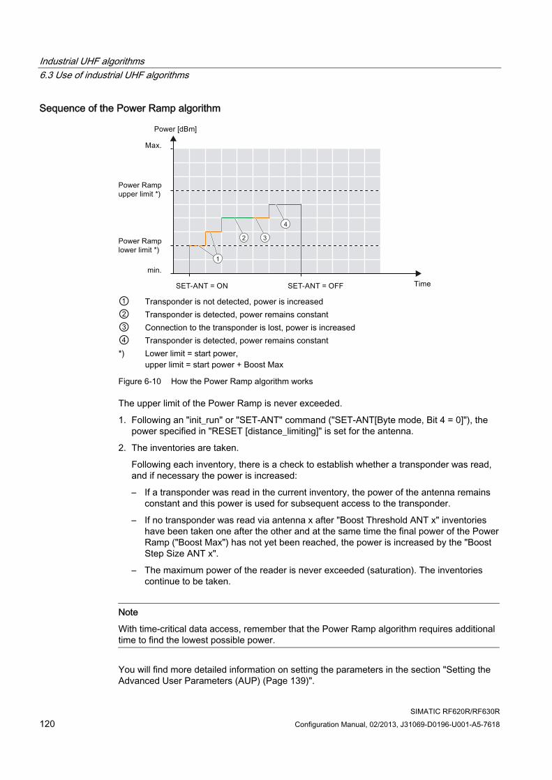
Industrial UHF algorithms 6.3 Use of industrial UHF algorithms
SIMATIC RF620R/RF630R 120 Configuration Manual, 02/2013, J31069-D0196-U001-A5-7618
Sequence of the Power Ramp algorithm
2
1
3
4
① Transponder is not detected, power is increased ② Transponder is detected, power remains constant ③ Connection to the transponder is lost, power is increased ④ Transponder is detected, power remains constant *) Lower limit = start power,
upper limit = start power + Boost Max
Figure 6-10 How the Power Ramp algorithm works
The upper limit of the Power Ramp is never exceeded.
1. Following an "init_run" or "SET-ANT" command ("SET-ANT[Byte mode, Bit 4 = 0]"), the power specified in "RESET [distance_limiting]" is set for the antenna.
2. The inventories are taken.
Following each inventory, there is a check to establish whether a transponder was read, and if necessary the power is increased:
– If a transponder was read in the current inventory, the power of the antenna remains constant and this power is used for subsequent access to the transponder.
– If no transponder was read via antenna x after "Boost Threshold ANT x" inventories have been taken one after the other and at the same time the final power of the Power Ramp ("Boost Max") has not yet been reached, the power is increased by the "Boost Step Size ANT x".
– The maximum power of the reader is never exceeded (saturation). The inventories continue to be taken.
Note
With time-critical data access, remember that the Power Ramp algorithm requires additional time to find the lowest possible power.
You will find more detailed information on setting the parameters in the section "Setting the Advanced User Parameters (AUP) (Page 139)".
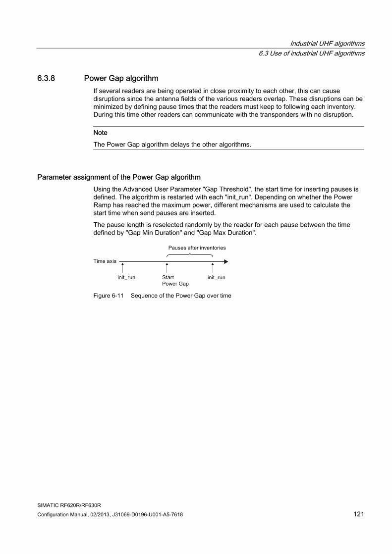
Industrial UHF algorithms 6.3 Use of industrial UHF algorithms
SIMATIC RF620R/RF630R Configuration Manual, 02/2013, J31069-D0196-U001-A5-7618 121
6.3.8 Power Gap algorithm If several readers are being operated in close proximity to each other, this can cause disruptions since the antenna fields of the various readers overlap. These disruptions can be minimized by defining pause times that the readers must keep to following each inventory. During this time other readers can communicate with the transponders with no disruption.
Note
The Power Gap algorithm delays the other algorithms.
Parameter assignment of the Power Gap algorithm Using the Advanced User Parameter "Gap Threshold", the start time for inserting pauses is defined. The algorithm is restarted with each "init_run". Depending on whether the Power Ramp has reached the maximum power, different mechanisms are used to calculate the start time when send pauses are inserted.
The pause length is reselected randomly by the reader for each pause between the time defined by "Gap Min Duration" and "Gap Max Duration".
Figure 6-11 Sequence of the Power Gap over time
Industrial UHF algorithms 6.3 Use of industrial UHF algorithms
SIMATIC RF620R/RF630R 122 Configuration Manual, 02/2013, J31069-D0196-U001-A5-7618
Sequence of the algorithm For the start time, it does not matter whether or not the inventory contains a transponder. After the number of inventories specified by "Gap Threshold", a pause is inserted following each inventory.
The aim is to give the Power Ramp algorithm priority and not to delay it with pauses. Depending on whether the Power Ramp has reached the maximum power, there are various different reactions:
● Power Ramp is not at maximum
For the start time, only inventories containing at least one transponder are counted. If an inventory does not contain a transponder the counter belonging to "Gap Threshold" is reset again.
If at least "Gap Threshold" inventories with at least one detected transponder are taken, a pause is inserted after each Inventory .
As soon as an inventory does not detect a transponder, the algorithm starts from the beginning again. This means that at least "Gap Threshold" inventories with at least one detected transponder must be taken again successfully before a pause is inserted.
● Power Rampis at maximum or not active
For the start time, it does not matter whether or not the inventory contains a transponder. After the number of inventories specified by "Gap Threshold", a pause is inserted following each inventory. The counter for the start time is no longer reset.
The parameter assignment mechanism of Power Ramp is described in the section "Power Ramp algorithm (Page 119)". You will find more detailed information on parameter assignment in the section "Setting the Advanced User Parameters (AUP) (Page 139)".
6.3.9 Filter mechanisms based on the RSSI or the EPC-IDs Each transponder (each EPC-ID recognized in the antenna field) is filtered after Collect Inventory in the following order:
1. RSSI Threshold
2. Black List
3. EPC Data Filter
Only when a transponder has met the criteria of RSSI Threshold, Black List and EPC Data Filter, is it processed by Smoothing or ITF followed by the UHF algorithms.
6.3.9.1 RSSI Threshold Using the RSSI Threshold all the transponders that have a lower RSSI value than the value defined in the RSSI Threshold are ignored and even during "Collect Inventory" they are not recognized.
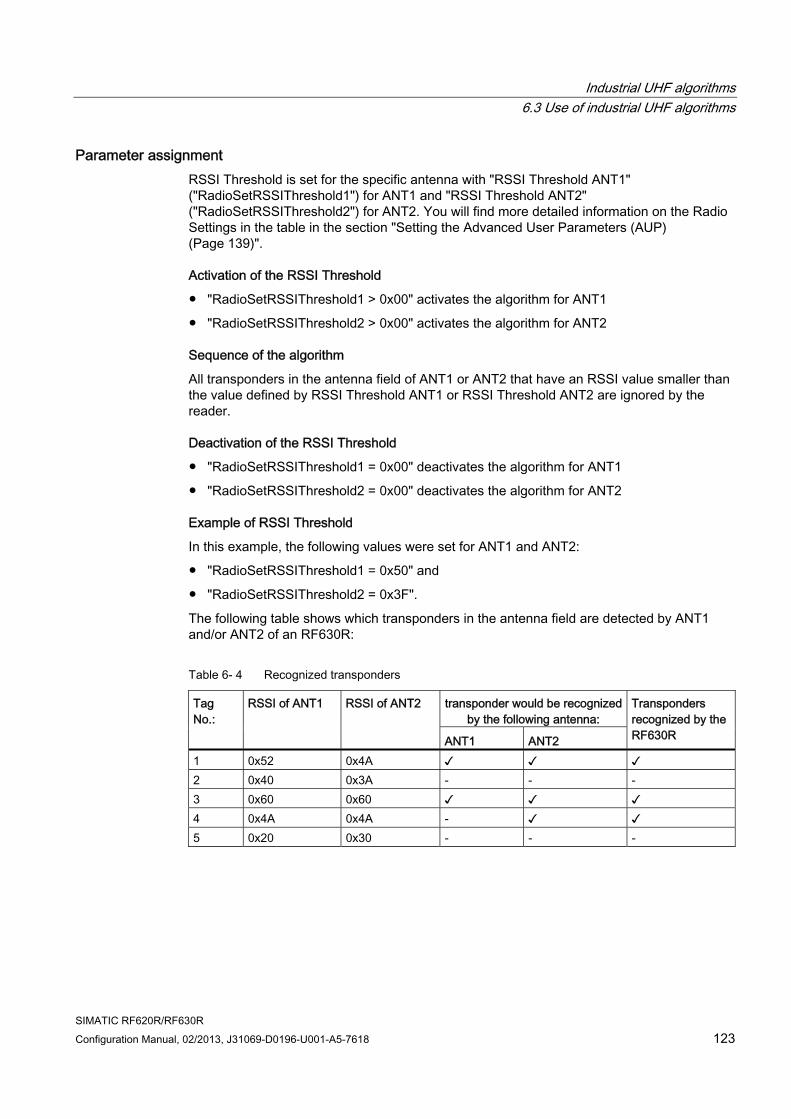
Industrial UHF algorithms 6.3 Use of industrial UHF algorithms
SIMATIC RF620R/RF630R Configuration Manual, 02/2013, J31069-D0196-U001-A5-7618 123
Parameter assignment RSSI Threshold is set for the specific antenna with "RSSI Threshold ANT1" ("RadioSetRSSIThreshold1") for ANT1 and "RSSI Threshold ANT2" ("RadioSetRSSIThreshold2") for ANT2. You will find more detailed information on the Radio Settings in the table in the section "Setting the Advanced User Parameters (AUP) (Page 139)".
Activation of the RSSI Threshold
● "RadioSetRSSIThreshold1 > 0x00" activates the algorithm for ANT1
● "RadioSetRSSIThreshold2 > 0x00" activates the algorithm for ANT2
Sequence of the algorithm
All transponders in the antenna field of ANT1 or ANT2 that have an RSSI value smaller than the value defined by RSSI Threshold ANT1 or RSSI Threshold ANT2 are ignored by the reader.
Deactivation of the RSSI Threshold
● "RadioSetRSSIThreshold1 = 0x00" deactivates the algorithm for ANT1
● "RadioSetRSSIThreshold2 = 0x00" deactivates the algorithm for ANT2
Example of RSSI Threshold
In this example, the following values were set for ANT1 and ANT2:
● "RadioSetRSSIThreshold1 = 0x50" and
● "RadioSetRSSIThreshold2 = 0x3F".
The following table shows which transponders in the antenna field are detected by ANT1 and/or ANT2 of an RF630R:
Table 6- 4 Recognized transponders
transponder would be recognized by the following antenna:
Tag No.:
RSSI of ANT1 RSSI of ANT2
ANT1 ANT2
Transponders recognized by the RF630R
1 0x52 0x4A ✓ ✓ ✓ 2 0x40 0x3A - - - 3 0x60 0x60 ✓ ✓ ✓ 4 0x4A 0x4A - ✓ ✓ 5 0x20 0x30 - - -
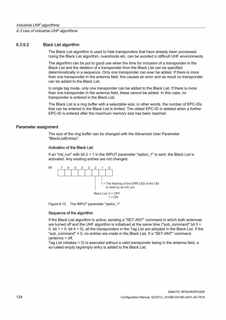
Industrial UHF algorithms 6.3 Use of industrial UHF algorithms
SIMATIC RF620R/RF630R 124 Configuration Manual, 02/2013, J31069-D0196-U001-A5-7618
6.3.9.2 Black List algorithm The Black List algorithm is used to hide transponders that have already been processed. Using the Black List algorithm, overshoots etc. can be avoided in difficult UHF environments.
The algorithm can be put to good use when the time for inclusion of a transponder in the Black List and the deletion of a transponder from the Black List can be specified deterministically in a sequence. Only one transponder can ever be added. If there is more than one transponder in the antenna field, this causes an error and as result no transponder can be added to the Black List.
In single tag mode, only one transponder can be added to the Black List. If there is more than one transponder in the antenna field, these cannot be added. In this case, no transponder is entered in the Black List.
The Black List is a ring buffer with a selectable size; in other words, the number of EPC-IDs that can be entered in the Black List is limited. The oldest EPC-ID is deleted when a further EPC-ID is entered after the maximum memory size has been reached.
Parameter assignment The size of the ring buffer can be changed with the Advanced User Parameter "BlackListEntries".
Activation of the Black List
If an "init_run" with bit 2 = 1 in the INPUT parameter "option_1" is sent, the Black List is activated. Any existing entries are not changed.
Figure 6-12 The INPUT parameter "option_1"
Sequence of the algorithm
If the Black List algorithm is active, sending a "SET-ANT" command in which both antennas are turned off and the UHF algorithm is initialized at the same time ("sub_command" bit 0 = 0, bit 1 = 0, bit 4 = 0), all the transponders in the Tag List are adopted in the Black List. If the "sub_command" ≠ 0, no entries are made in the Black List. If a "SET-ANT" command (antenna = off, Tag List initialize = 0) is executed without a valid transponder being in the antenna field, a so-called empty tag/empty entry is added to the Black List.
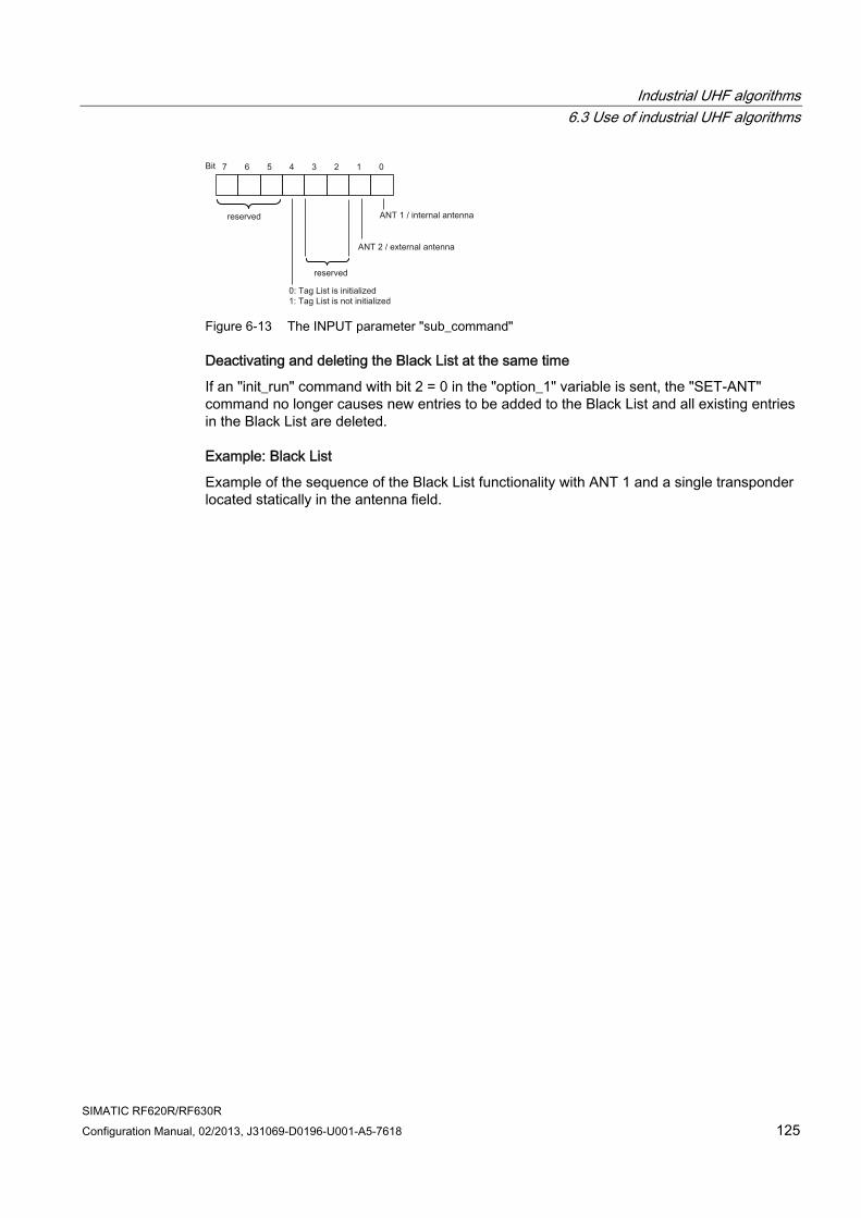
Industrial UHF algorithms 6.3 Use of industrial UHF algorithms
SIMATIC RF620R/RF630R Configuration Manual, 02/2013, J31069-D0196-U001-A5-7618 125
Figure 6-13 The INPUT parameter "sub_command"
Deactivating and deleting the Black List at the same time
If an "init_run" command with bit 2 = 0 in the "option_1" variable is sent, the "SET-ANT" command no longer causes new entries to be added to the Black List and all existing entries in the Black List are deleted.
Example: Black List
Example of the sequence of the Black List functionality with ANT 1 and a single transponder located statically in the antenna field.
Industrial UHF algorithms 6.3 Use of industrial UHF algorithms
SIMATIC RF620R/RF630R 126 Configuration Manual, 02/2013, J31069-D0196-U001-A5-7618
● Assigning parameters to a reader and initializing the Black List:
– 1. Turn on Black List functionality: "init_run" command with bit 2 = 1 in the variable "option_1", and turn on the presence check with "MDS_control = 1".
– 2. Turn on ANT 1, turn off ANT 2: "SET-ANT" command with bit 4 = 0, bit 1 = 0, bit 0 = 1 in "sub_command".
(Note no entry is made in the Black List here because bit 0 = 1.)
– 3. The transponder is detected, its presence is signaled via the controller ("MDS_control = 1")
● Enter transponder in the Black List:
– 4. Turn off antennas: "SET-ANT" command with bit 4 = 0, bit 1 = 0, bit 0 = 0 in "sub_command".
(The transponder detected in step 3 is entered in the Black List. The transponder is no longer recognized by the reader.)
– 5. Turn on antenna as in step 2: "SET-ANT" command with bit 4 = 0, bit 1 = 0, bit 0 = 1 in "sub_command".
(No entry is made in the Black List here because bit 0 = 1.)
– 6. Turn off antennas: "SET-ANT" command with bit 4 = 0, bit 1 = 0, bit 0 = 0 in "sub_command".
If no transponder was detected, an empty entry is made in the Black List.
Note Changing the size of the ring buffer during operation
Note that if the size of the ring buffer is changed, the Black List is not changed. The size of the ring buffer is adapted only with the next entry in the Black List.
Example: The size is set to 5 and all 5 entries have transponder IDs. If the size is now changed to 0, all 5 entries remain active. The size is changed to 0 and all entries are deleted only when there is a renewed attempt to make an entry in the Black List (regardless of whether this is a transponder ID or empty entry).
Note Entry of detected transponders in the Black List
Detected transponders are the transponders that the reader acknowledges as detected to the application.
If more than one transponder runs through the various mechanisms in single tag mode, the error "0x1D" - "too many transponders in field" is generated. This means that no transponder is signaled as detected to the outside and therefore no transponder is entered in the Black List. As in the other cases, the content of the ring buffer is shifted by 1 place (in other words an empty entry is generated). If the ring buffer is already full, the oldest transponder entry is removed.
You will find more detailed information on parameter assignment in the section "Setting the Advanced User Parameters (AUP) (Page 139)".
Industrial UHF algorithms 6.3 Use of industrial UHF algorithms
SIMATIC RF620R/RF630R Configuration Manual, 02/2013, J31069-D0196-U001-A5-7618 127
6.3.9.3 EPC Data Filter The EPC Data Filter is used to filter out transponders from further processing if they have fixed data content in the EPC-ID or the PC (Protocol Control). If the EPC Data Filter is active, each transponder remaining in the Tag List is checked by the EPC Data Filter for the expected and the actual result and if applicable discarded. Here, you can decide between direct or inverse filtering.
You can define the filter using the following filter properties:
● Filter length
Specifies the number of bytes to be filtered.
● Filter criterion
Specifies whether filtering will be direct or inverse.
● Filter data
Specifies the data content to be filtered.
● Filter mask
Specifies which bits of the filter data are checked.
Parameter assignment The parameters of the EPC Data Filter are assigned using UDT 350.
Activation of the EPC Data Filter
To enable the EPC Data Filter, use a write command to the address "0xFEF2". The write command must have a defined data length of 148 (0x94) bytes and a pointer to UDT 350 with a filter length > 0 bytes. The filter length must match the number of masked bytes to be filtered.
Note
For the EPC Data Filter to be successfully set on the reader, the number of bytes with a value > 0x00 must match the value specified in address +0.0 of UDT 350.
Sequence of the algorithm
If the EPC Data Filter is active, all transponders in the antenna field are evaluated and if necessary removed according to the set filter criteria.
● Direct filtering: The filter criterion (address "+1.0") in UDT 350 has the value "0x00"
If the expected and actual result match, the transponder is removed.
● Inverse filtering: The filter criterion (address "+1.0") in UDT 350 has the value "0x01"
If the expected and actual result do not match, the transponder is removed.
Industrial UHF algorithms 6.3 Use of industrial UHF algorithms
SIMATIC RF620R/RF630R 128 Configuration Manual, 02/2013, J31069-D0196-U001-A5-7618
Note Transponders with undefined data relevant for filtering are separated out
If EPC data is not defined for a transponder that will be checked by the EPC Data Filter, the filter result will be evaluated as a mismatch between expected and actual data and the transponder separated out.
Deactivating and deleting the EPC Data Filter at the same time
The EPC Data Filter is initialized and deactivated at the same time by:
● Restarting the reader
● Executing a write command to the address "0xFEF2". The write command must have a defined data length of 148 (0x94) bytes, a pointer to UDT 350 and a filter length = 0 bytes and number of masked bytes = 0.
Reading out the EPC Data Filter
The EPC Data Filter can be read out with a read command to address "0xFEF2" with a length of 148 bytes. The arrangement of the bytes corresponds to that of UDT 350.
Procedure To determine the EPC Data Filter , follow the steps below:
1. Determine the requirements.
2. Determine the filter mask and filter data based on the requirements.
3. Decide whether you want to use direct or inverse filtering.
4. Count the number of bytes in the filter masks of address "+78 ... +147" of UDT 350 that have a value > 0x00.
5. Enter the filter length, the filter criterion, the filter data and the filter mask in UDT 350.
6. Enable the EPC Data Filter with a write command to the address "0xFEF2". The write command must have defined data length of 148 bytes and a pointer to UDT 350.
Note Setting the filter mask
Which bits of the filter data are checked is specified in the filter mask by setting the individual bits (e.g. bit 0 = 1). All other bits of the filter data are irrelevant for filtering.
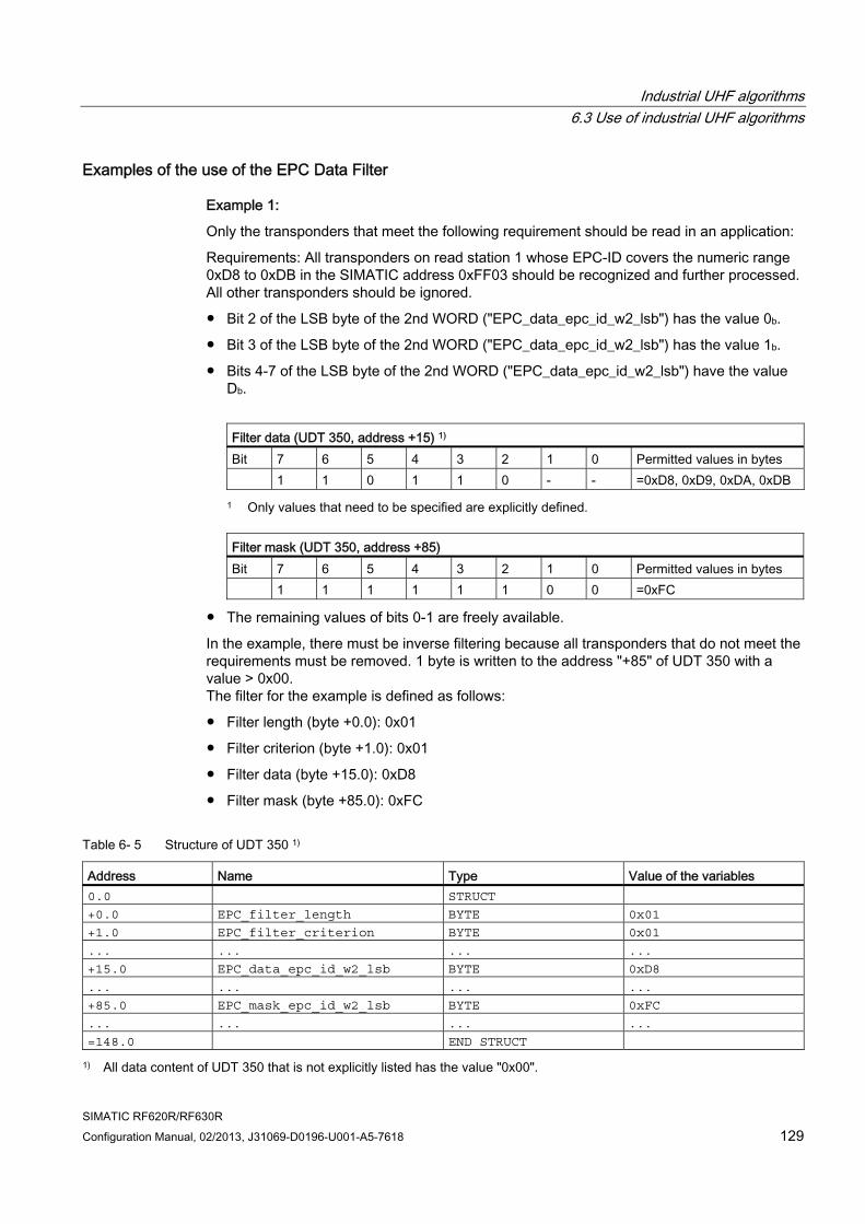
Industrial UHF algorithms 6.3 Use of industrial UHF algorithms
SIMATIC RF620R/RF630R Configuration Manual, 02/2013, J31069-D0196-U001-A5-7618 129
Examples of the use of the EPC Data Filter
Example 1:
Only the transponders that meet the following requirement should be read in an application:
Requirements: All transponders on read station 1 whose EPC-ID covers the numeric range 0xD8 to 0xDB in the SIMATIC address 0xFF03 should be recognized and further processed. All other transponders should be ignored.
● Bit 2 of the LSB byte of the 2nd WORD ("EPC_data_epc_id_w2_lsb") has the value 0b.
● Bit 3 of the LSB byte of the 2nd WORD ("EPC_data_epc_id_w2_lsb") has the value 1b.
● Bits 4-7 of the LSB byte of the 2nd WORD ("EPC_data_epc_id_w2_lsb") have the value Db.
Filter data (UDT 350, address +15) 1) Bit 7 6 5 4 3 2 1 0 Permitted values in bytes 1 1 0 1 1 0 - - =0xD8, 0xD9, 0xDA, 0xDB
1 Only values that need to be specified are explicitly defined.
Filter mask (UDT 350, address +85) Bit 7 6 5 4 3 2 1 0 Permitted values in bytes 1 1 1 1 1 1 0 0 =0xFC
● The remaining values of bits 0-1 are freely available.
In the example, there must be inverse filtering because all transponders that do not meet the requirements must be removed. 1 byte is written to the address "+85" of UDT 350 with a value > 0x00. The filter for the example is defined as follows:
● Filter length (byte +0.0): 0x01
● Filter criterion (byte +1.0): 0x01
● Filter data (byte +15.0): 0xD8
● Filter mask (byte +85.0): 0xFC
Table 6- 5 Structure of UDT 350 1)
Address Name Type Value of the variables 0.0 STRUCT
+0.0 EPC_filter_length BYTE 0x01
+1.0 EPC_filter_criterion BYTE 0x01
... ... ... ...
+15.0 EPC_data_epc_id_w2_lsb BYTE 0xD8
... ... ... ...
+85.0 EPC_mask_epc_id_w2_lsb BYTE 0xFC
... ... ... ...
=148.0 END STRUCT
1) All data content of UDT 350 that is not explicitly listed has the value "0x00".
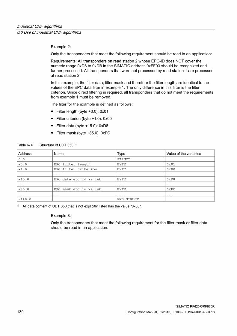
Industrial UHF algorithms 6.3 Use of industrial UHF algorithms
SIMATIC RF620R/RF630R 130 Configuration Manual, 02/2013, J31069-D0196-U001-A5-7618
Example 2:
Only the transponders that meet the following requirement should be read in an application:
Requirements: All transponders on read station 2 whose EPC-ID does NOT cover the numeric range 0xD8 to 0xDB in the SIMATIC address 0xFF03 should be recognized and further processed. All transponders that were not processed by read station 1 are processed at read station 2.
In this example, the filter data, filter mask and therefore the filter length are identical to the values of the EPC data filter in example 1. The only difference in this filter is the filter criterion. Since direct filtering is required, all transponders that do not meet the requirements from example 1 must be removed.
The filter for the example is defined as follows:
● Filter length (byte +0.0): 0x01
● Filter criterion (byte +1.0): 0x00
● Filter data (byte +15.0): 0xD8
● Filter mask (byte +85.0): 0xFC
Table 6- 6 Structure of UDT 350 1)
Address Name Type Value of the variables 0.0 STRUCT
+0.0 EPC_filter_length BYTE 0x01
+1.0 EPC_filter_criterion BYTE 0x00
... ... ... ...
+15.0 EPC_data_epc_id_w2_lsb BYTE 0xD8
... ... ... ...
+85.0 EPC_mask_epc_id_w2_lsb BYTE 0xFC
... ... ... ...
=148.0 END STRUCT
1) All data content of UDT 350 that is not explicitly listed has the value "0x00".
Example 3:
Only the transponders that meet the following requirement for the filter mask or filter data should be read in an application:
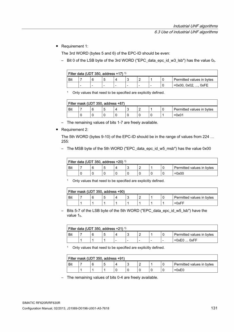
Industrial UHF algorithms 6.3 Use of industrial UHF algorithms
SIMATIC RF620R/RF630R Configuration Manual, 02/2013, J31069-D0196-U001-A5-7618 131
● Requirement 1:
The 3rd WORD (bytes 5 and 6) of the EPC-ID should be even:
– Bit 0 of the LSB byte of the 3rd WORD ("EPC_data_epc_id_w3_lsb") has the value 0b.
Filter data (UDT 350, address +17) 1) Bit 7 6 5 4 3 2 1 0 Permitted values in bytes - - - - - - - 0 =0x00, 0x02, ..., 0xFE
1 Only values that need to be specified are explicitly defined.
Filter mask (UDT 350, address +87) Bit 7 6 5 4 3 2 1 0 Permitted values in bytes 0 0 0 0 0 0 0 1 =0x01
– The remaining values of bits 1-7 are freely available.
● Requirement 2:
The 5th WORD (bytes 9-10) of the EPC-ID should be in the range of values from 224 … 255:
– The MSB byte of the 5th WORD ("EPC_data_epc_id_w5_msb") has the value 0x00
Filter data (UDT 350, address +20) 1) Bit 7 6 5 4 3 2 1 0 Permitted values in bytes 0 0 0 0 0 0 0 0 =0x00
1 Only values that need to be specified are explicitly defined.
Filter mask (UDT 350, address +90) Bit 7 6 5 4 3 2 1 0 Permitted values in bytes 1 1 1 1 1 1 1 1 =0xFF
– Bits 5-7 of the LSB byte of the 5th WORD ("EPC_data_epc_id_w5_lsb") have the value 1b.
Filter data (UDT 350, address +21) 1) Bit 7 6 5 4 3 2 1 0 Permitted values in bytes 1 1 1 - - - - - =0xE0 ... 0xFF
1 Only values that need to be specified are explicitly defined.
Filter mask (UDT 350, address +91) Bit 7 6 5 4 3 2 1 0 Permitted values in bytes 1 1 1 0 0 0 0 0 =0xE0
– The remaining values of bits 0-4 are freely available.
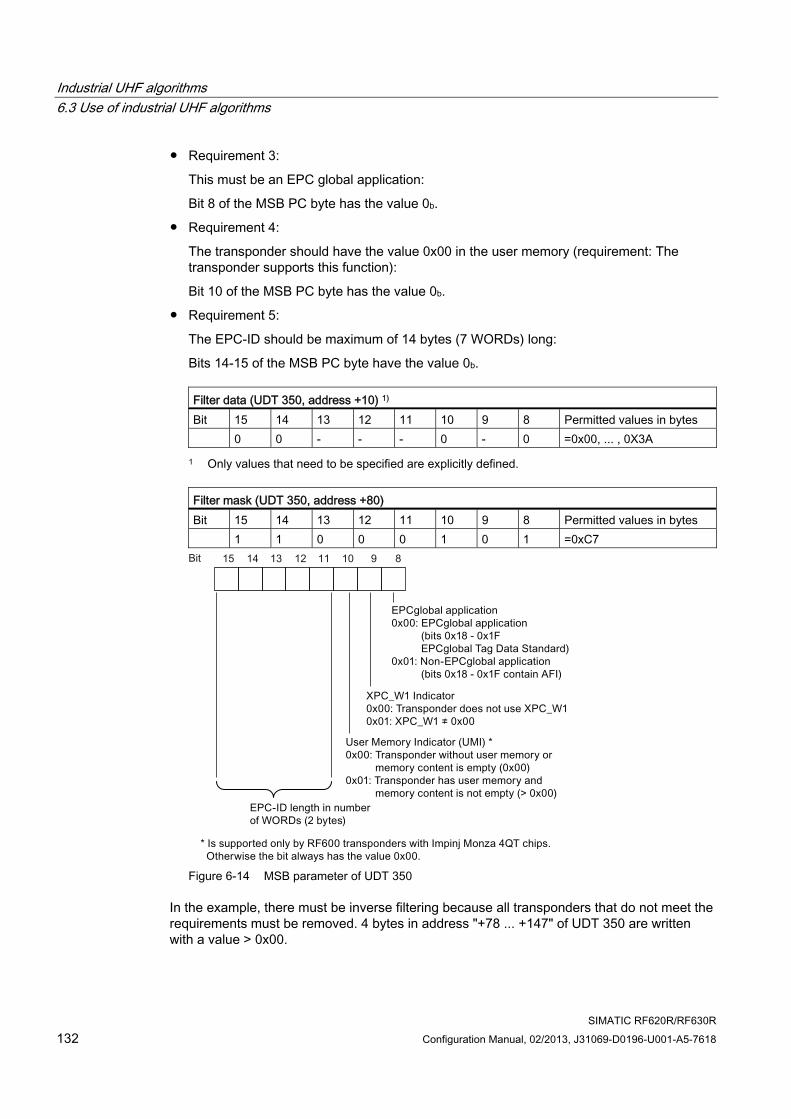
Industrial UHF algorithms 6.3 Use of industrial UHF algorithms
SIMATIC RF620R/RF630R 132 Configuration Manual, 02/2013, J31069-D0196-U001-A5-7618
● Requirement 3:
This must be an EPC global application:
Bit 8 of the MSB PC byte has the value 0b.
● Requirement 4:
The transponder should have the value 0x00 in the user memory (requirement: The transponder supports this function):
Bit 10 of the MSB PC byte has the value 0b.
● Requirement 5:
The EPC-ID should be maximum of 14 bytes (7 WORDs) long:
Bits 14-15 of the MSB PC byte have the value 0b.
Filter data (UDT 350, address +10) 1) Bit 15 14 13 12 11 10 9 8 Permitted values in bytes 0 0 - - - 0 - 0 =0x00, ... , 0X3A
1 Only values that need to be specified are explicitly defined.
Filter mask (UDT 350, address +80) Bit 15 14 13 12 11 10 9 8 Permitted values in bytes 1 1 0 0 0 1 0 1 =0xC7
Figure 6-14 MSB parameter of UDT 350
In the example, there must be inverse filtering because all transponders that do not meet the requirements must be removed. 4 bytes in address "+78 ... +147" of UDT 350 are written with a value > 0x00.
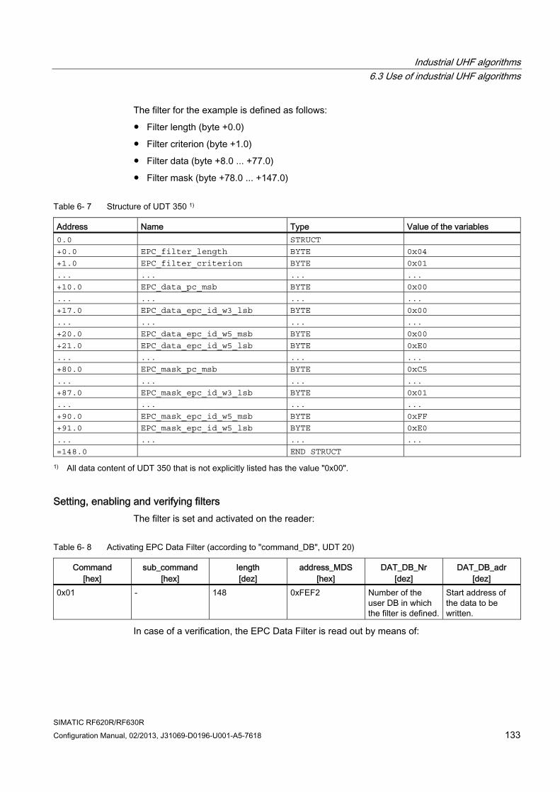
Industrial UHF algorithms 6.3 Use of industrial UHF algorithms
SIMATIC RF620R/RF630R Configuration Manual, 02/2013, J31069-D0196-U001-A5-7618 133
The filter for the example is defined as follows:
● Filter length (byte +0.0)
● Filter criterion (byte +1.0)
● Filter data (byte +8.0 ... +77.0)
● Filter mask (byte +78.0 ... +147.0)
Table 6- 7 Structure of UDT 350 1)
Address Name Type Value of the variables 0.0 STRUCT
+0.0 EPC_filter_length BYTE 0x04
+1.0 EPC_filter_criterion BYTE 0x01
... ... ... ...
+10.0 EPC_data_pc_msb BYTE 0x00
... ... ... ...
+17.0 EPC_data_epc_id_w3_lsb BYTE 0x00
... ... ... ...
+20.0 EPC_data_epc_id_w5_msb BYTE 0x00
+21.0 EPC_data_epc_id_w5_lsb BYTE 0xE0
... ... ... ...
+80.0 EPC_mask_pc_msb BYTE 0xC5
... ... ... ...
+87.0 EPC_mask_epc_id_w3_lsb BYTE 0x01
... ... ... ...
+90.0 EPC_mask_epc_id_w5_msb BYTE 0xFF
+91.0 EPC_mask_epc_id_w5_lsb BYTE 0xE0
... ... ... ...
=148.0 END STRUCT
1) All data content of UDT 350 that is not explicitly listed has the value "0x00".
Setting, enabling and verifying filters The filter is set and activated on the reader:
Table 6- 8 Activating EPC Data Filter (according to "command_DB", UDT 20)
Command [hex]
sub_command [hex]
length [dez]
address_MDS [hex]
DAT_DB_Nr [dez]
DAT_DB_adr [dez]
0x01 - 148 0xFEF2 Number of the user DB in which the filter is defined.
Start address of the data to be written.
In case of a verification, the EPC Data Filter is read out by means of:
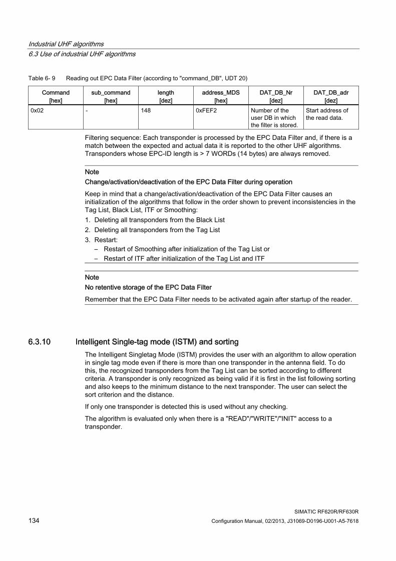
Industrial UHF algorithms 6.3 Use of industrial UHF algorithms
SIMATIC RF620R/RF630R 134 Configuration Manual, 02/2013, J31069-D0196-U001-A5-7618
Table 6- 9 Reading out EPC Data Filter (according to "command_DB", UDT 20)
Command [hex]
sub_command [hex]
length [dez]
address_MDS [hex]
DAT_DB_Nr [dez]
DAT_DB_adr [dez]
0x02 - 148 0xFEF2 Number of the user DB in which the filter is stored.
Start address of the read data.
Filtering sequence: Each transponder is processed by the EPC Data Filter and, if there is a match between the expected and actual data it is reported to the other UHF algorithms. Transponders whose EPC-ID length is > 7 WORDs (14 bytes) are always removed.
Note Change/activation/deactivation of the EPC Data Filter during operation
Keep in mind that a change/activation/deactivation of the EPC Data Filter causes an initialization of the algorithms that follow in the order shown to prevent inconsistencies in the Tag List, Black List, ITF or Smoothing: 1. Deleting all transponders from the Black List 2. Deleting all transponders from the Tag List 3. Restart:
– Restart of Smoothing after initialization of the Tag List or – Restart of ITF after initialization of the Tag List and ITF
Note No retentive storage of the EPC Data Filter
Remember that the EPC Data Filter needs to be activated again after startup of the reader.
6.3.10 Intelligent Single-tag mode (ISTM) and sorting The Intelligent Singletag Mode (ISTM) provides the user with an algorithm to allow operation in single tag mode even if there is more than one transponder in the antenna field. To do this, the recognized transponders from the Tag List can be sorted according to different criteria. A transponder is only recognized as being valid if it is first in the list following sorting and also keeps to the minimum distance to the next transponder. The user can select the sort criterion and the distance.
If only one transponder is detected this is used without any checking.
The algorithm is evaluated only when there is a "READ"/"WRITE"/"INIT" access to a transponder.
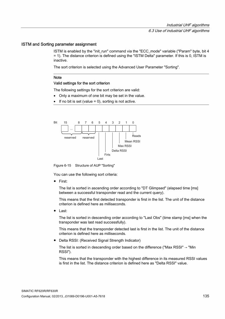
Industrial UHF algorithms 6.3 Use of industrial UHF algorithms
SIMATIC RF620R/RF630R Configuration Manual, 02/2013, J31069-D0196-U001-A5-7618 135
ISTM and Sorting parameter assignment ISTM is enabled by the "init_run" command via the "ECC_mode" variable ("Param" byte, bit 4 = 1). The distance criterion is defined using the "ISTM Delta" parameter. If this is 0, ISTM is inactive.
The sort criterion is selected using the Advanced User Parameter "Sorting".
Note Valid settings for the sort criterion
The following settings for the sort criterion are valid: • Only a maximum of one bit may be set in the value. • If no bit is set (value = 0), sorting is not active.
Figure 6-15 Structure of AUP "Sorting"
You can use the following sort criteria:
● First:
The list is sorted in ascending order according to "DT Glimpsed" (elapsed time [ms] between a successful transponder read and the current query).
This means that the first detected transponder is first in the list. The unit of the distance criterion is defined here as milliseconds.
● Last:
The list is sorted in descending order according to "Last Obs" (time stamp [ms] when the transponder was last read successfully).
This means that the transponder detected last is first in the list. The unit of the distance criterion is defined here as milliseconds.
● Delta RSSI: (Received Signal Strength Indicator)
The list is sorted in descending order based on the difference ("Max RSSI" → "Min RSSI").
This means that the transponder with the highest difference in its measured RSSI values is first in the list. The distance criterion is defined here as "Delta RSSI" value.
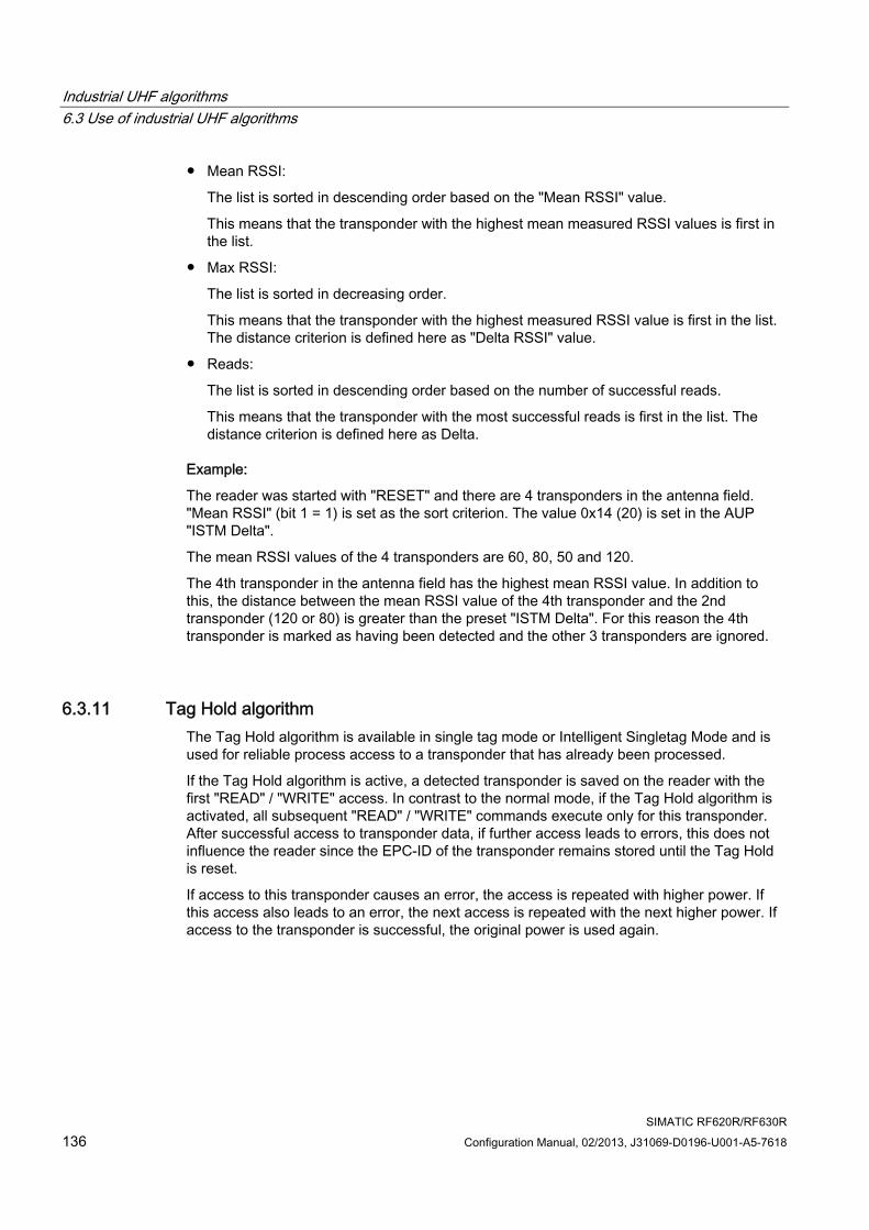
Industrial UHF algorithms 6.3 Use of industrial UHF algorithms
SIMATIC RF620R/RF630R 136 Configuration Manual, 02/2013, J31069-D0196-U001-A5-7618
● Mean RSSI:
The list is sorted in descending order based on the "Mean RSSI" value.
This means that the transponder with the highest mean measured RSSI values is first in the list.
● Max RSSI:
The list is sorted in decreasing order.
This means that the transponder with the highest measured RSSI value is first in the list. The distance criterion is defined here as "Delta RSSI" value.
● Reads:
The list is sorted in descending order based on the number of successful reads.
This means that the transponder with the most successful reads is first in the list. The distance criterion is defined here as Delta.
Example:
The reader was started with "RESET" and there are 4 transponders in the antenna field. "Mean RSSI" (bit 1 = 1) is set as the sort criterion. The value 0x14 (20) is set in the AUP "ISTM Delta".
The mean RSSI values of the 4 transponders are 60, 80, 50 and 120.
The 4th transponder in the antenna field has the highest mean RSSI value. In addition to this, the distance between the mean RSSI value of the 4th transponder and the 2nd transponder (120 or 80) is greater than the preset "ISTM Delta". For this reason the 4th transponder is marked as having been detected and the other 3 transponders are ignored.
6.3.11 Tag Hold algorithm The Tag Hold algorithm is available in single tag mode or Intelligent Singletag Mode and is used for reliable process access to a transponder that has already been processed.
If the Tag Hold algorithm is active, a detected transponder is saved on the reader with the first "READ" / "WRITE" access. In contrast to the normal mode, if the Tag Hold algorithm is activated, all subsequent "READ" / "WRITE" commands execute only for this transponder. After successful access to transponder data, if further access leads to errors, this does not influence the reader since the EPC-ID of the transponder remains stored until the Tag Hold is reset.
If access to this transponder causes an error, the access is repeated with higher power. If this access also leads to an error, the next access is repeated with the next higher power. If access to the transponder is successful, the original power is used again.
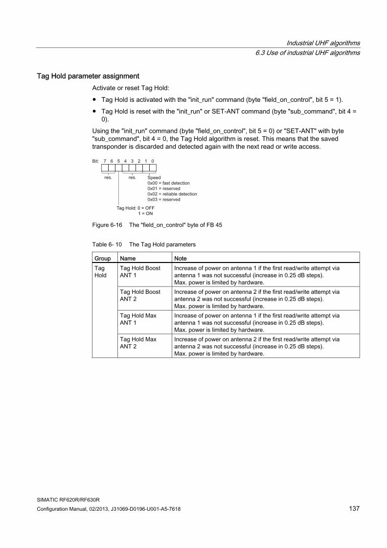
Industrial UHF algorithms 6.3 Use of industrial UHF algorithms
SIMATIC RF620R/RF630R Configuration Manual, 02/2013, J31069-D0196-U001-A5-7618 137
Tag Hold parameter assignment Activate or reset Tag Hold:
● Tag Hold is activated with the "init_run" command (byte "field_on_control", bit 5 = 1).
● Tag Hold is reset with the "init_run" or SET-ANT command (byte "sub_command", bit 4 = 0).
Using the "init_run" command (byte "field_on_control", bit 5 = 0) or "SET-ANT" with byte "sub_command", bit 4 = 0, the Tag Hold algorithm is reset. This means that the saved transponder is discarded and detected again with the next read or write access.
Figure 6-16 The "field_on_control" byte of FB 45
Table 6- 10 The Tag Hold parameters
Group Name Note Tag Hold Boost ANT 1
Increase of power on antenna 1 if the first read/write attempt via antenna 1 was not successful (increase in 0.25 dB steps). Max. power is limited by hardware.
Tag Hold Boost ANT 2
Increase of power on antenna 2 if the first read/write attempt via antenna 2 was not successful (increase in 0.25 dB steps). Max. power is limited by hardware.
Tag Hold Max ANT 1
Increase of power on antenna 1 if the first read/write attempt via antenna 1 was not successful (increase in 0.25 dB steps). Max. power is limited by hardware.
Tag Hold
Tag Hold Max ANT 2
Increase of power on antenna 2 if the first read/write attempt via antenna 2 was not successful (increase in 0.25 dB steps). Max. power is limited by hardware.
Industrial UHF algorithms 6.3 Use of industrial UHF algorithms
SIMATIC RF620R/RF630R 138 Configuration Manual, 02/2013, J31069-D0196-U001-A5-7618
Effect on presence
Note that the Tag Hold algorithm affects the presence message:
● Without the Tag Hold algorithm, the presence always indicates that one or more transponders were detected. A transponder counts as detected if it was signaled by the Smoothing or the ITF algorithm as being valid ("Observed"). The presence also indicates the number of transponders detected at the same time. This presence response does not depend on any other algorithms.
● As soon as the Tag Hold algorithm has held an EPC-ID, presence only signals the transponder with this EPC-ID.
If, for example, Smoothing is active, the present status is cancelled as soon as the transponder with this EPC-ID is no longer detected as being valid. If this transponder is detected by Smoothing again, presence indicates precisely one transponder. This occurs regardless of whether or not other transponders are detected as being valid by Smoothing .
● As soon as the Tag Hold algorithm has held an EPC-ID, an attempt is made immediately to access the transponder with "READ" or "WRITE". In other words, in this situation no presence is reported.
In contrast to this, without a held EPC-ID, inventories are always taken first to detect a transponder in the antenna field. The actual "READ" or "WRITE" access is sent only after a transponder has been detected (= presence).
You will find more detailed information on parameter assignment of Tag Hold in the section "Setting the Advanced User Parameters (AUP) (Page 139)".
Industrial UHF algorithms 6.4 Setting the Advanced User Parameters (AUP)
SIMATIC RF620R/RF630R Configuration Manual, 02/2013, J31069-D0196-U001-A5-7618 139
6.4 Setting the Advanced User Parameters (AUP) To assign parameters for the industrial UHF algorithms, the mechanism described below is available. Here, the reader is informed that the writing ("WRITE" command) of data to reserved SIMATIC addresses involves data access to internal parameters and not to transponders.
Note Avoiding inconsistencies with "init_run"
To avoid inconsistencies during operation and in data management, after setting a AUP, run an "init_run".
Parameter sets There are two different parameter sets that can be selected with the value of bits 0 and 1 in byte "field_ON_control" of the "init_run" command.
With the factory setting, the two parameter sets only differ in the "Observed Threshold Count". The "Observed Threshold Count" specifies for Smoothing how often a transponder must be read before it is included in the Tag List :
● Parameter set "1" (fast, bit 0 = 0 / bit 1 = 0) has "Observed Threshold Count = 1"
Transponders are recognized as being valid with the first inventory.
● Parameter set "2" (reliable, bit 0 = 0 / bit 1 = 1) has "Observed Threshold Count = 5"
Transponders must be detected five times in succession. Overshoot and reflections are filtered out by this.
The settings of the AUP always apply only to the currently selected parameter set. Each AUP is referenced using a unique ID.
Reading and writing parameters ● The ID of the required AUP is written to address "0xFEF3".
● The AUP is set by sending a write command to the address "0xFEF7" with an ID and parameter value.
● The AUP is read out by sending a read command to address "0xFEF7". As the return value, the ID and the parameter value are sent. To make this possible, however, the ID of the AUP must already have been written to the address "0xFEF3". The read therefore relates to the last AUP-ID written to the address "0xFEF3".
● Addressing "0xFEF3" and "0xFEF7" is exclusive and only possible using direct addressing; in other words, read/write commands to other addresses (for example read command to "0xFEF2" with the length of 5 or "0xFEF3" with the length of 8 do not lead to functional access. This avoids inconsistencies occurring.
● Sending a write command to the address "0xFEF7" only with an ID and no parameter value resets this AUP to the factory setting.
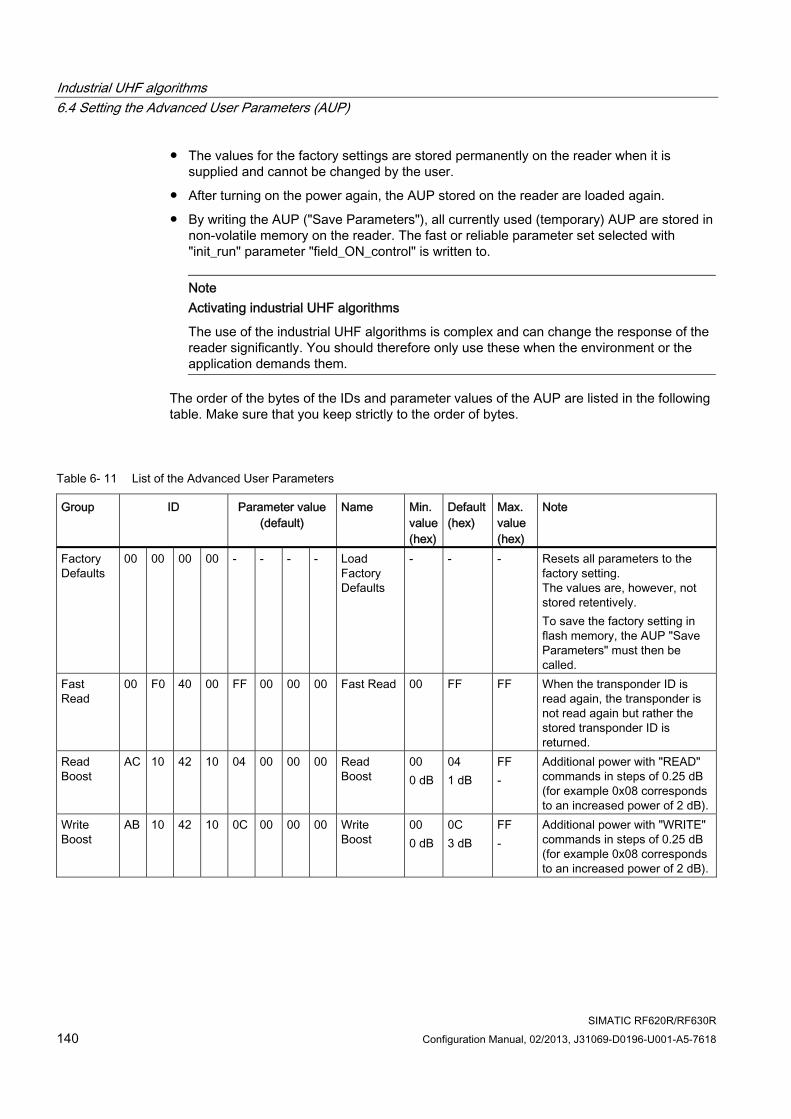
Industrial UHF algorithms 6.4 Setting the Advanced User Parameters (AUP)
SIMATIC RF620R/RF630R 140 Configuration Manual, 02/2013, J31069-D0196-U001-A5-7618
● The values for the factory settings are stored permanently on the reader when it is supplied and cannot be changed by the user.
● After turning on the power again, the AUP stored on the reader are loaded again.
● By writing the AUP ("Save Parameters"), all currently used (temporary) AUP are stored in non-volatile memory on the reader. The fast or reliable parameter set selected with "init_run" parameter "field_ON_control" is written to.
Note Activating industrial UHF algorithms
The use of the industrial UHF algorithms is complex and can change the response of the reader significantly. You should therefore only use these when the environment or the application demands them.
The order of the bytes of the IDs and parameter values of the AUP are listed in the following table. Make sure that you keep strictly to the order of bytes.
Table 6- 11 List of the Advanced User Parameters
Group ID Parameter value (default)
Name Min. value (hex)
Default (hex)
Max. value (hex)
Note
Factory Defaults
00 00 00 00 - - - - Load Factory Defaults
- - - Resets all parameters to the factory setting. The values are, however, not stored retentively. To save the factory setting in flash memory, the AUP "Save Parameters" must then be called.
Fast Read
00 F0 40 00 FF 00 00 00 Fast Read 00 FF FF When the transponder ID is read again, the transponder is not read again but rather the stored transponder ID is returned.
Read Boost
AC 10 42 10 04 00 00 00 Read Boost
00 0 dB
04 1 dB
FF -
Additional power with "READ" commands in steps of 0.25 dB (for example 0x08 corresponds to an increased power of 2 dB).
Write Boost
AB 10 42 10 0C 00 00 00 Write Boost
00 0 dB
0C 3 dB
FF -
Additional power with "WRITE" commands in steps of 0.25 dB (for example 0x08 corresponds to an increased power of 2 dB).
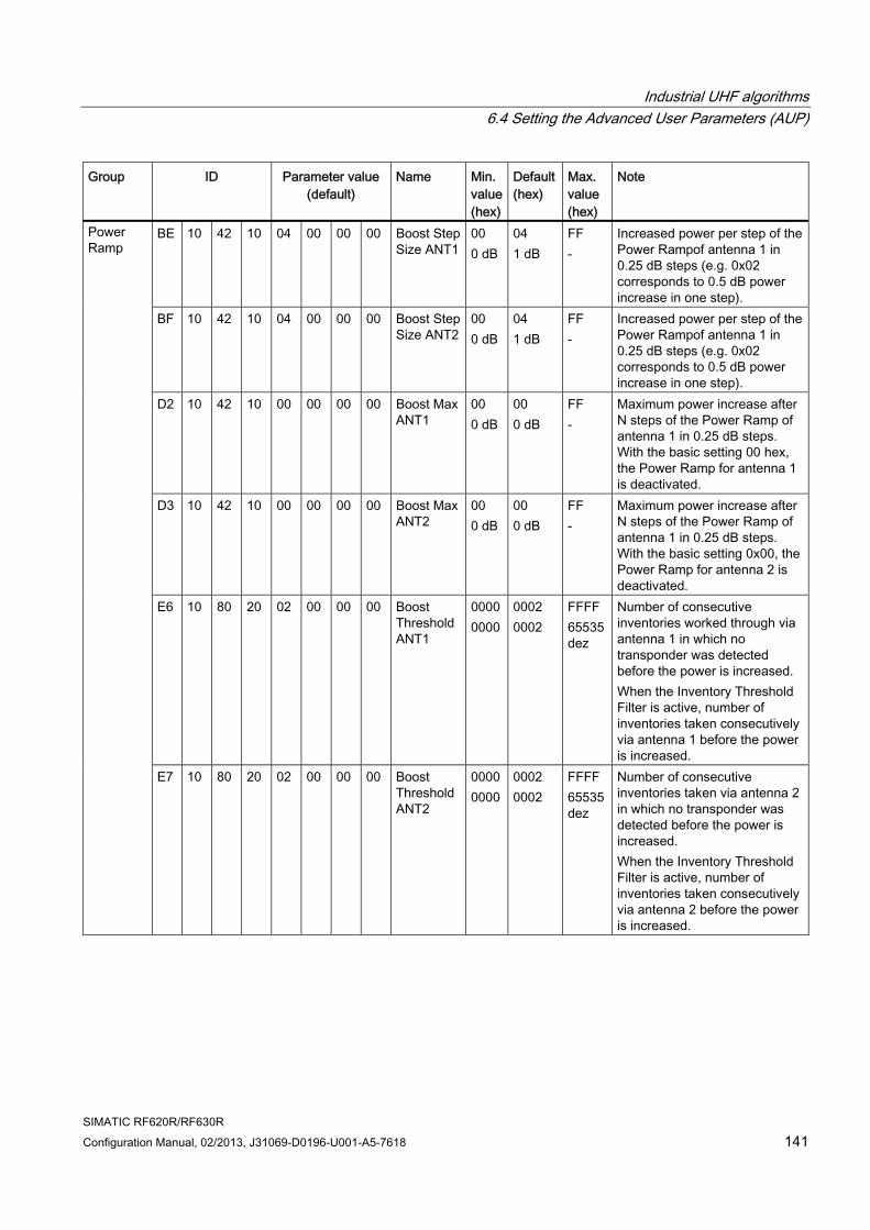
Industrial UHF algorithms 6.4 Setting the Advanced User Parameters (AUP)
SIMATIC RF620R/RF630R Configuration Manual, 02/2013, J31069-D0196-U001-A5-7618 141
Group ID Parameter value(default)
Name Min. value (hex)
Default (hex)
Max. value (hex)
Note
BE 10 42 10 04 00 00 00 Boost Step Size ANT1
00 0 dB
04 1 dB
FF -
Increased power per step of the Power Rampof antenna 1 in 0.25 dB steps (e.g. 0x02 corresponds to 0.5 dB power increase in one step).
BF 10 42 10 04 00 00 00 Boost Step Size ANT2
00 0 dB
04 1 dB
FF -
Increased power per step of the Power Rampof antenna 1 in 0.25 dB steps (e.g. 0x02 corresponds to 0.5 dB power increase in one step).
D2 10 42 10 00 00 00 00 Boost Max ANT1
00 0 dB
00 0 dB
FF -
Maximum power increase after N steps of the Power Ramp of antenna 1 in 0.25 dB steps. With the basic setting 00 hex, the Power Ramp for antenna 1 is deactivated.
D3 10 42 10 00 00 00 00 Boost Max ANT2
00 0 dB
00 0 dB
FF -
Maximum power increase after N steps of the Power Ramp of antenna 1 in 0.25 dB steps. With the basic setting 0x00, the Power Ramp for antenna 2 is deactivated.
E6 10 80 20 02 00 00 00 Boost Threshold ANT1
0000 0000
0002 0002
FFFF 65535 dez
Number of consecutive inventories worked through via antenna 1 in which no transponder was detected before the power is increased. When the Inventory Threshold Filter is active, number of inventories taken consecutively via antenna 1 before the power is increased.
Power Ramp
E7 10 80 20 02 00 00 00 Boost Threshold ANT2
0000 0000
0002 0002
FFFF 65535 dez
Number of consecutive inventories taken via antenna 2 in which no transponder was detected before the power is increased. When the Inventory Threshold Filter is active, number of inventories taken consecutively via antenna 2 before the power is increased.
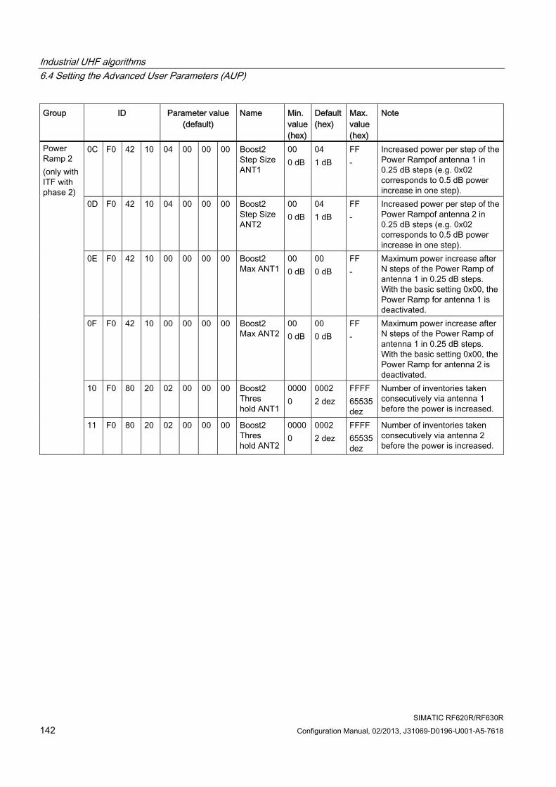
Industrial UHF algorithms 6.4 Setting the Advanced User Parameters (AUP)
SIMATIC RF620R/RF630R 142 Configuration Manual, 02/2013, J31069-D0196-U001-A5-7618
Group ID Parameter value (default)
Name Min. value (hex)
Default (hex)
Max. value (hex)
Note
0C F0 42 10 04 00 00 00 Boost2 Step Size ANT1
00 0 dB
04 1 dB
FF -
Increased power per step of the Power Rampof antenna 1 in 0.25 dB steps (e.g. 0x02 corresponds to 0.5 dB power increase in one step).
0D F0 42 10 04 00 00 00 Boost2 Step Size ANT2
00 0 dB
04 1 dB
FF -
Increased power per step of the Power Rampof antenna 2 in 0.25 dB steps (e.g. 0x02 corresponds to 0.5 dB power increase in one step).
0E F0 42 10 00 00 00 00 Boost2 Max ANT1
00 0 dB
00 0 dB
FF -
Maximum power increase after N steps of the Power Ramp of antenna 1 in 0.25 dB steps. With the basic setting 0x00, the Power Ramp for antenna 1 is deactivated.
0F F0 42 10 00 00 00 00 Boost2 Max ANT2
00 0 dB
00 0 dB
FF -
Maximum power increase after N steps of the Power Ramp of antenna 1 in 0.25 dB steps. With the basic setting 0x00, the Power Ramp for antenna 2 is deactivated.
10 F0 80 20 02 00 00 00 Boost2 Thres hold ANT1
0000 0
0002 2 dez
FFFF 65535 dez
Number of inventories taken consecutively via antenna 1 before the power is increased.
Power Ramp 2 (only with ITF with phase 2)
11 F0 80 20 02 00 00 00 Boost2 Thres hold ANT2
0000 0
0002 2 dez
FFFF 65535 dez
Number of inventories taken consecutively via antenna 2 before the power is increased.
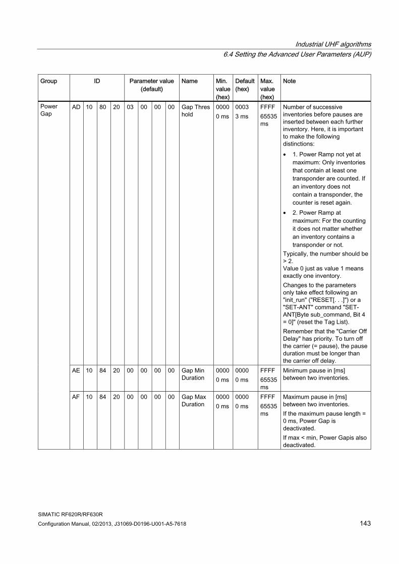
Industrial UHF algorithms 6.4 Setting the Advanced User Parameters (AUP)
SIMATIC RF620R/RF630R Configuration Manual, 02/2013, J31069-D0196-U001-A5-7618 143
Group ID Parameter value(default)
Name Min. value (hex)
Default (hex)
Max. value (hex)
Note
AD 10 80 20 03 00 00 00 Gap Threshold
0000 0 ms
0003 3 ms
FFFF 65535 ms
Number of successive inventories before pauses are inserted between each further inventory. Here, it is important to make the following distinctions: • 1. Power Ramp not yet at
maximum: Only inventories that contain at least one transponder are counted. If an inventory does not contain a transponder, the counter is reset again.
• 2. Power Ramp at maximum: For the counting it does not matter whether an inventory contains a transponder or not.
Typically, the number should be > 2. Value 0 just as value 1 means exactly one inventory. Changes to the parameters only take effect following an "init_run" ("RESET[. . .]") or a "SET-ANT" command "SET-ANT[Byte sub_command, Bit 4 = 0]" (reset the Tag List). Remember that the "Carrier Off Delay" has priority. To turn off the carrier (= pause), the pause duration must be longer than the carrier off delay.
AE 10 84 20 00 00 00 00 Gap Min Duration
0000 0 ms
0000 0 ms
FFFF 65535 ms
Minimum pause in [ms] between two inventories.
Power Gap
AF 10 84 20 00 00 00 00 Gap Max Duration
0000 0 ms
0000 0 ms
FFFF 65535 ms
Maximum pause in [ms] between two inventories. If the maximum pause length = 0 ms, Power Gap is deactivated. If max < min, Power Gapis also deactivated.
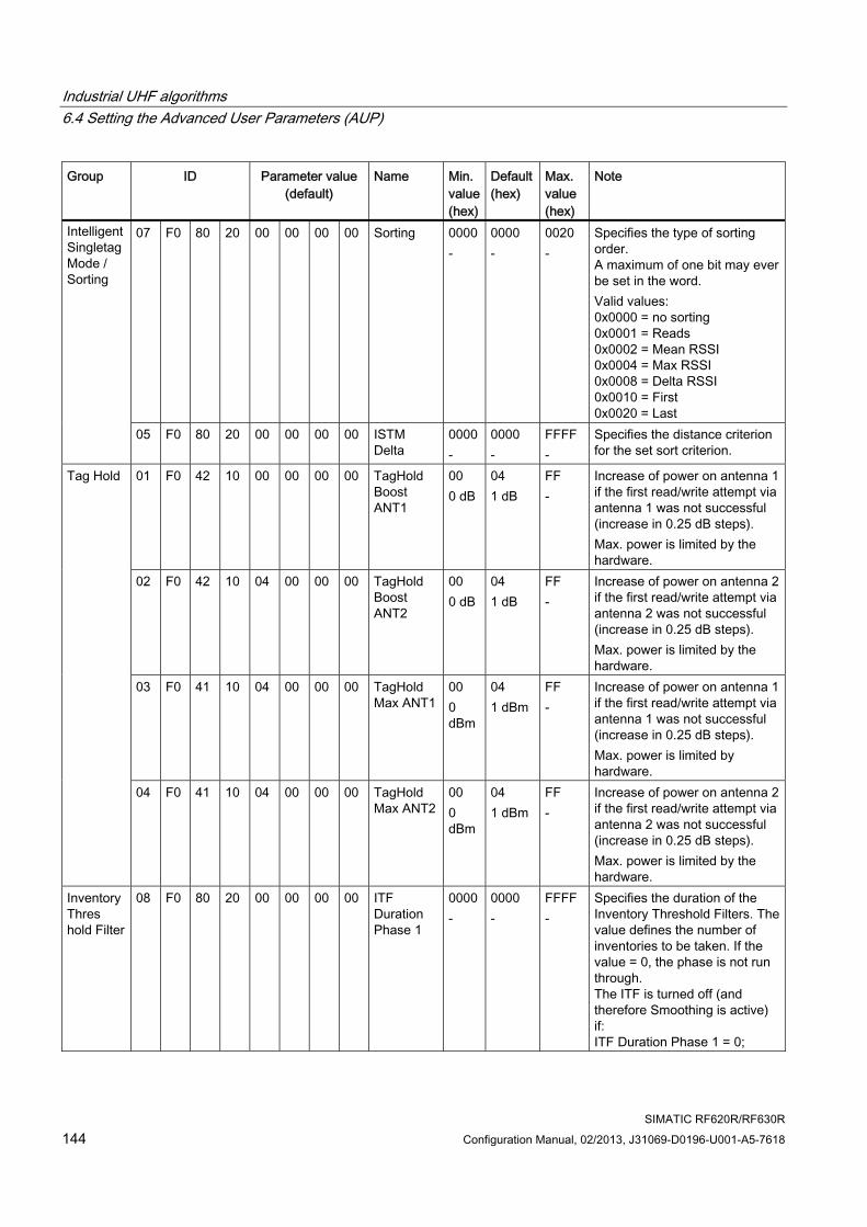
Industrial UHF algorithms 6.4 Setting the Advanced User Parameters (AUP)
SIMATIC RF620R/RF630R 144 Configuration Manual, 02/2013, J31069-D0196-U001-A5-7618
Group ID Parameter value (default)
Name Min. value (hex)
Default (hex)
Max. value (hex)
Note
07 F0 80 20 00 00 00 00 Sorting 0000 -
0000 -
0020 -
Specifies the type of sorting order. A maximum of one bit may ever be set in the word. Valid values: 0x0000 = no sorting 0x0001 = Reads 0x0002 = Mean RSSI 0x0004 = Max RSSI 0x0008 = Delta RSSI 0x0010 = First 0x0020 = Last
Intelligent Singletag Mode / Sorting
05 F0 80 20 00 00 00 00 ISTM Delta
0000 -
0000 -
FFFF -
Specifies the distance criterion for the set sort criterion.
01 F0 42 10 00 00 00 00 TagHold Boost ANT1
00 0 dB
04 1 dB
FF -
Increase of power on antenna 1 if the first read/write attempt via antenna 1 was not successful (increase in 0.25 dB steps). Max. power is limited by the hardware.
02 F0 42 10 04 00 00 00 TagHold Boost ANT2
00 0 dB
04 1 dB
FF -
Increase of power on antenna 2 if the first read/write attempt via antenna 2 was not successful (increase in 0.25 dB steps). Max. power is limited by the hardware.
03 F0 41 10 04 00 00 00 TagHold Max ANT1
00 0 dBm
04 1 dBm
FF -
Increase of power on antenna 1 if the first read/write attempt via antenna 1 was not successful (increase in 0.25 dB steps). Max. power is limited by hardware.
Tag Hold
04 F0 41 10 04 00 00 00 TagHold Max ANT2
00 0 dBm
04 1 dBm
FF -
Increase of power on antenna 2 if the first read/write attempt via antenna 2 was not successful (increase in 0.25 dB steps). Max. power is limited by the hardware.
Inventory Thres hold Filter
08 F0 80 20 00 00 00 00 ITF Duration Phase 1
0000 -
0000 -
FFFF -
Specifies the duration of the Inventory Threshold Filters. The value defines the number of inventories to be taken. If the value = 0, the phase is not run through. The ITF is turned off (and therefore Smoothing is active) if: ITF Duration Phase 1 = 0;
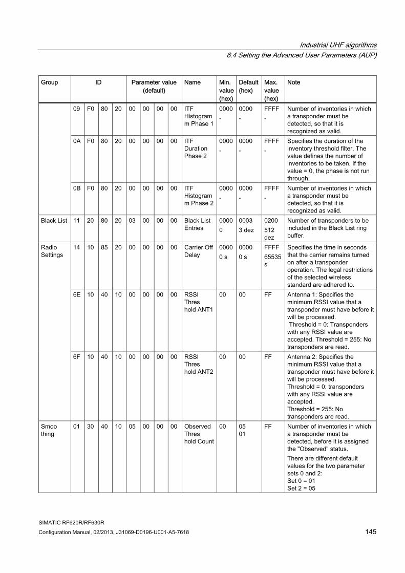
Industrial UHF algorithms 6.4 Setting the Advanced User Parameters (AUP)
SIMATIC RF620R/RF630R Configuration Manual, 02/2013, J31069-D0196-U001-A5-7618 145
Group ID Parameter value(default)
Name Min. value (hex)
Default (hex)
Max. value (hex)
Note
09 F0 80 20 00 00 00 00 ITF Histogramm Phase 1
0000 -
0000 -
FFFF -
Number of inventories in which a transponder must be detected, so that it is recognized as valid.
0A F0 80 20 00 00 00 00 ITF Duration Phase 2
0000 -
0000 -
FFFF -
Specifies the duration of the inventory threshold filter. The value defines the number of inventories to be taken. If the value = 0, the phase is not run through.
0B F0 80 20 00 00 00 00 ITF Histogramm Phase 2
0000 -
0000 -
FFFF -
Number of inventories in which a transponder must be detected, so that it is recognized as valid.
Black List 11 20 80 20 03 00 00 00 Black List Entries
0000 0
0003 3 dez
0200 512 dez
Number of transponders to be included in the Black List ring buffer.
14 10 85 20 00 00 00 00 Carrier Off Delay
0000 0 s
0000 0 s
FFFF 65535 s
Specifies the time in seconds that the carrier remains turned on after a transponder operation. The legal restrictions of the selected wireless standard are adhered to.
6E 10 40 10 00 00 00 00 RSSI Thres hold ANT1
00 00 FF Antenna 1: Specifies the minimum RSSI value that a transponder must have before it will be processed. Threshold = 0: Transponders with any RSSI value are accepted. Threshold = 255: No transponders are read.
Radio Settings
6F 10 40 10 00 00 00 00 RSSI Thres hold ANT2
00 00 FF Antenna 2: Specifies the minimum RSSI value that a transponder must have before it will be processed. Threshold = 0: transponders with any RSSI value are accepted. Threshold = 255: No transponders are read.
Smoo thing
01 30 40 10 05 00 00 00 Observed Thres hold Count
00 05 01
FF Number of inventories in which a transponder must be detected, before it is assigned the "Observed" status. There are different default values for the two parameter sets 0 and 2: Set 0 = 01 Set 2 = 05
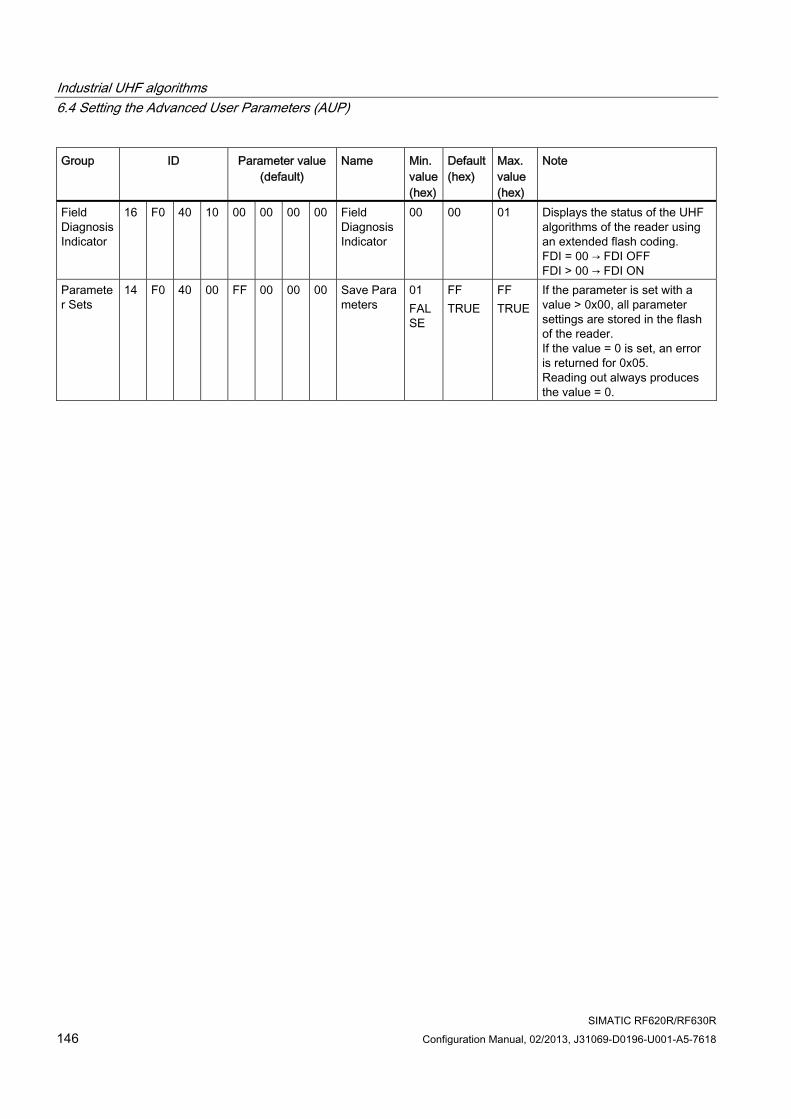
Industrial UHF algorithms 6.4 Setting the Advanced User Parameters (AUP)
SIMATIC RF620R/RF630R 146 Configuration Manual, 02/2013, J31069-D0196-U001-A5-7618
Group ID Parameter value (default)
Name Min. value (hex)
Default (hex)
Max. value (hex)
Note
Field Diagnosis Indicator
16 F0 40 10 00 00 00 00 Field Diagnosis Indicator
00 00 01 Displays the status of the UHF algorithms of the reader using an extended flash coding. FDI = 00 → FDI OFF FDI > 00 → FDI ON
Parameter Sets
14 F0 40 00 FF 00 00 00 Save Parameters
01 FALSE
FF TRUE
FF TRUE
If the parameter is set with a value > 0x00, all parameter settings are stored in the flash of the reader. If the value = 0 is set, an error is returned for 0x05. Reading out always produces the value = 0.
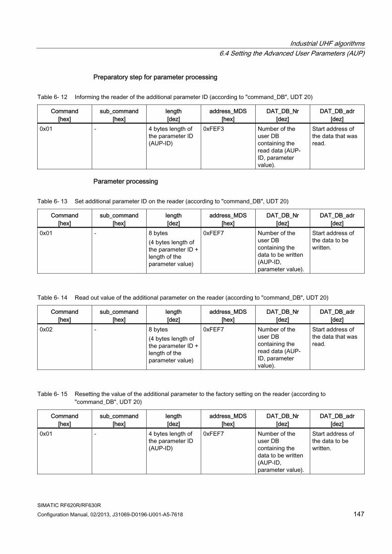
Industrial UHF algorithms 6.4 Setting the Advanced User Parameters (AUP)
SIMATIC RF620R/RF630R Configuration Manual, 02/2013, J31069-D0196-U001-A5-7618 147
Preparatory step for parameter processing
Table 6- 12 Informing the reader of the additional parameter ID (according to "command_DB", UDT 20)
Command [hex]
sub_command [hex]
length [dez]
address_MDS [hex]
DAT_DB_Nr [dez]
DAT_DB_adr [dez]
0x01 - 4 bytes length of the parameter ID (AUP-ID)
0xFEF3 Number of the user DB containing the read data (AUP-ID, parameter value).
Start address of the data that was read.
Parameter processing
Table 6- 13 Set additional parameter ID on the reader (according to "command_DB", UDT 20)
Command [hex]
sub_command [hex]
length [dez]
address_MDS [hex]
DAT_DB_Nr [dez]
DAT_DB_adr [dez]
0x01 - 8 bytes (4 bytes length of the parameter ID + length of the parameter value)
0xFEF7 Number of the user DB containing the data to be written (AUP-ID, parameter value).
Start address of the data to be written.
Table 6- 14 Read out value of the additional parameter on the reader (according to "command_DB", UDT 20)
Command [hex]
sub_command [hex]
length [dez]
address_MDS [hex]
DAT_DB_Nr [dez]
DAT_DB_adr [dez]
0x02 - 8 bytes (4 bytes length of the parameter ID + length of the parameter value)
0xFEF7 Number of the user DB containing the read data (AUP-ID, parameter value).
Start address of the data that was read.
Table 6- 15 Resetting the value of the additional parameter to the factory setting on the reader (according to "command_DB", UDT 20)
Command [hex]
sub_command [hex]
length [dez]
address_MDS [hex]
DAT_DB_Nr [dez]
DAT_DB_adr [dez]
0x01 - 4 bytes length of the parameter ID (AUP-ID)
0xFEF7 Number of the user DB containing the data to be written (AUP-ID, parameter value).
Start address of the data to be written.
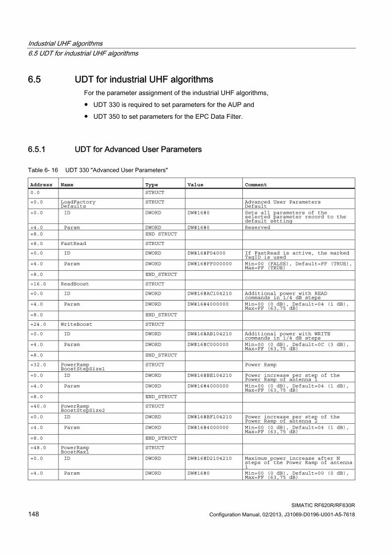
Industrial UHF algorithms 6.5 UDT for industrial UHF algorithms
SIMATIC RF620R/RF630R 148 Configuration Manual, 02/2013, J31069-D0196-U001-A5-7618
6.5 UDT for industrial UHF algorithms For the parameter assignment of the industrial UHF algorithms,
● UDT 330 is required to set parameters for the AUP and
● UDT 350 to set parameters for the EPC Data Filter.
6.5.1 UDT for Advanced User Parameters
Table 6- 16 UDT 330 "Advanced User Parameters"
Address Name Type Value Comment 0.0 STRUCT +0.0 LoadFactory
Defaults STRUCT Advanced User Parameters
Default +0.0 ID DWORD DW#16#0 Sets all parameters of the
selected parameter record to the default setting
+4.0 Param DWORD DW#16#0 Reserved =8.0 END STRUCT +8.0 FastRead STRUCT +0.0 ID DWORD DW#16#F04000 If FastRead is active, the marked
TagID is used +4.0 Param DWORD DW#16#FF000000 Min=00 (FALSE), Default=FF (TRUE),
Max=FF (TRUE) =8.0 END_STRUCT +16.0 ReadBoost STRUCT +0.0 ID DWORD DW#16#AC104210 Additional power with READ
commands in 1/4 dB steps +4.0 Param DWORD DW#16#4000000 Min=00 (0 dB), Default=04 (1 dB),
Max=FF (63,75 dB) =8.0 END_STRUCT +24.0 WriteBoost STRUCT +0.0 ID DWORD DW#16#AB104210 Additional power with WRITE
commands in 1/4 dB steps +4.0 Param DWORD DW#16#C000000 Min=00 (0 dB), Default=0C (3 dB),
Max=FF (63,75 dB) =8.0 END_STRUCT +32.0 PowerRamp
BoostStepSize1 STRUCT Power Ramp
+0.0 ID DWORD DW#16#BE104210 Power increase per step of the Power Ramp of antenna 1
+4.0 Param DWORD DW#16#4000000 Min=00 (0 dB), Default=04 (1 dB), Max=FF (63,75 dB)
=8.0 END_STRUCT +40.0 PowerRamp
BoostStepSize2 STRUCT +0.0 ID DWORD DW#16#BF104210 Power increase per step of the
Power Ramp of antenna 2 +4.0 Param DWORD DW#16#4000000 Min=00 (0 dB), Default=04 (1 dB),
Max=FF (63,75 dB) =8.0 END_STRUCT +48.0 PowerRamp
BoostMax1 STRUCT
+0.0 ID DWORD DW#16#D2104210 Maximum power increase after N steps of the Power Ramp of antenna 1
+4.0 Param DWORD DW#16#0 Min=00 (0 dB), Default=00 (0 dB), Max=FF (63,75 dB)
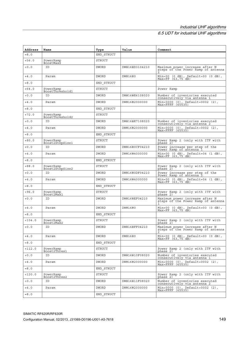
Industrial UHF algorithms 6.5 UDT for industrial UHF algorithms
SIMATIC RF620R/RF630R Configuration Manual, 02/2013, J31069-D0196-U001-A5-7618 149
Address Name Type Value Comment =8.0 END_STRUCT +56.0 PowerRamp
BoostMax2 STRUCT
+0.0 ID DWORD DW#16#D3104210 Maximum power increase after N steps of the Power Ramp of antenna 2
+4.0 Param DWORD DW#16#0 Min=00 (0 dB), Default=00 (0 dB), Max=FF (63,75 dB)
=8.0 END_STRUCT +64.0 PowerRamp
BoostThreshold1 STRUCT Power Ramp
+0.0 ID DWORD DW#16#E6108020 Number of inventories executed consecutively via antenna 1
+4.0 Param DWORD DW#16#2000000 Min=0000 (0), Default=0002 (2), Max=FFFF (65535)
=8.0 END_STRUCT +72.0 PowerRamp
BoostThreshold2 STRUCT
+0.0 ID DWORD DW#16#E7108020 Number of inventories executed consecutively via antenna 2
+4.0 Param DWORD DW#16#2000000 Min=0000 (0), Default=0002 (2), Max=FFFF (65535)
=8.0 END_STRUCT +80.0 PowerRamp
Boost2StepSize1 STRUCT Power Ramp 2 (only with ITF with phase 2)
+0.0 ID DWORD DW#16#0CF04210 Power increase per step of the Power Ramp of antenna 1
+4.0 Param DWORD DW#16#4000000 Min=00 (0 dB), Default=04 (1 dB), Max=FF (63,75 dB)
=8.0 END_STRUCT +88.0 PowerRamp
Boost2StepSize2 STRUCT Power Ramp 2 (only with ITF with
phase 2) +0.0 ID DWORD DW#16#0DF04210 Power increase per step of the
Power Ramp of antenna 2 +4.0 Param DWORD DW#16#4000000 Min=00 (0 dB), Default=04 (1 dB),
Max=FF (63,75 dB) =8.0 END_STRUCT +96.0 PowerRamp
Boost2Max1 STRUCT Power Ramp 2 (only with ITF with
phase 2) +0.0 ID DWORD DW#16#EF04210 Maximum power increase after N
steps of the Power Ramp of antenna 1
+4.0 Param DWORD DW#16#0 Min=00 (0 dB), Default=00 (0 dB), Max=FF (63,75 dB)
=8.0 END_STRUCT +104.0 PowerRamp
Boost2Max2 STRUCT Power Ramp 2 (only with ITF with
phase 2) +0.0 ID DWORD DW#16#FF04210 Maximum power increase after N
steps of the Power Ramp of antenna 2
+4.0 Param DWORD DW#16#0 Min=00 (0 dB), Default=00 (0 dB), Max=FF (63,75 dB)
=8.0 END_STRUCT +112.0 PowerRamp
Boost2Thres1 STRUCT Power Ramp 2 (only with ITF with phase 2)
+0.0 ID DWORD DW#16#10F08020 Number of inventories executed consecutively via antenna 1
+4.0 Param DWORD DW#16#2000000 Min=0000 (0), Default=0002 (2), Max=FFFF (65535)
=8.0 END_STRUCT +120.0 PowerRamp
Boost2Thres2 STRUCT Power Ramp 2 (only with ITF with
phase 2) +0.0 ID DWORD DW#16#11F08020 Number of inventories executed
consecutively via antenna 2 +4.0 Param DWORD DW#16#2000000 Min=0000 (0), Default=0002 (2),
Max=FFFF (65535) =8.0 END_STRUCT
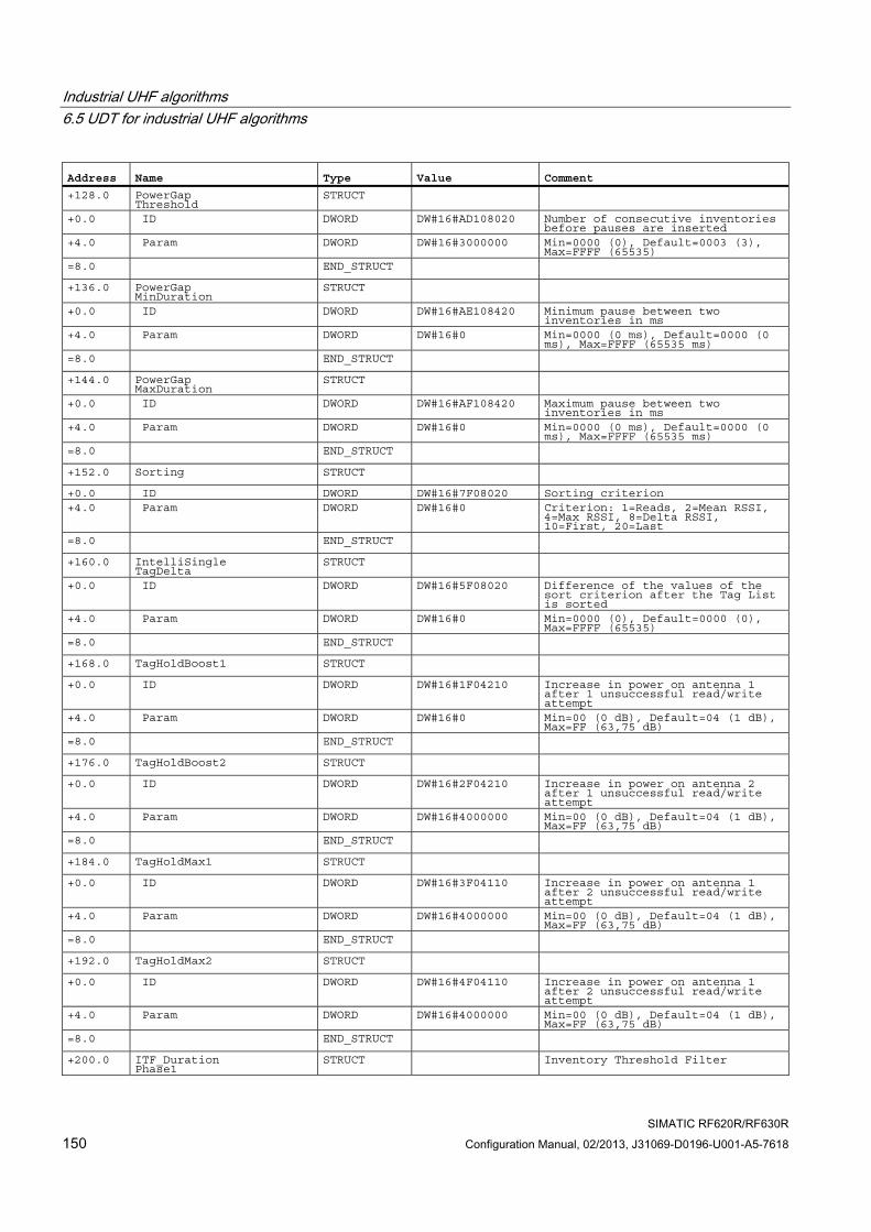
Industrial UHF algorithms 6.5 UDT for industrial UHF algorithms
SIMATIC RF620R/RF630R 150 Configuration Manual, 02/2013, J31069-D0196-U001-A5-7618
Address Name Type Value Comment +128.0 PowerGap
Threshold STRUCT
+0.0 ID DWORD DW#16#AD108020 Number of consecutive inventories before pauses are inserted
+4.0 Param DWORD DW#16#3000000 Min=0000 (0), Default=0003 (3), Max=FFFF (65535)
=8.0 END_STRUCT +136.0 PowerGap
MinDuration STRUCT
+0.0 ID DWORD DW#16#AE108420 Minimum pause between two inventories in ms
+4.0 Param DWORD DW#16#0 Min=0000 (0 ms), Default=0000 (0 ms), Max=FFFF (65535 ms)
=8.0 END_STRUCT +144.0 PowerGap
MaxDuration STRUCT
+0.0 ID DWORD DW#16#AF108420 Maximum pause between two inventories in ms
+4.0 Param DWORD DW#16#0 Min=0000 (0 ms), Default=0000 (0 ms), Max=FFFF (65535 ms)
=8.0 END_STRUCT +152.0 Sorting STRUCT +0.0 ID DWORD DW#16#7F08020 Sorting criterion +4.0 Param DWORD DW#16#0 Criterion: 1=Reads, 2=Mean RSSI,
4=Max RSSI, 8=Delta RSSI, 10=First, 20=Last
=8.0 END_STRUCT +160.0 IntelliSingle
TagDelta STRUCT +0.0 ID DWORD DW#16#5F08020 Difference of the values of the
sort criterion after the Tag List is sorted
+4.0 Param DWORD DW#16#0 Min=0000 (0), Default=0000 (0), Max=FFFF (65535)
=8.0 END_STRUCT +168.0 TagHoldBoost1 STRUCT +0.0 ID DWORD DW#16#1F04210 Increase in power on antenna 1
after 1 unsuccessful read/write attempt
+4.0 Param DWORD DW#16#0 Min=00 (0 dB), Default=04 (1 dB), Max=FF (63,75 dB)
=8.0 END_STRUCT +176.0 TagHoldBoost2 STRUCT +0.0 ID DWORD DW#16#2F04210 Increase in power on antenna 2
after 1 unsuccessful read/write attempt
+4.0 Param DWORD DW#16#4000000 Min=00 (0 dB), Default=04 (1 dB), Max=FF (63,75 dB)
=8.0 END_STRUCT +184.0 TagHoldMax1 STRUCT +0.0 ID DWORD DW#16#3F04110 Increase in power on antenna 1
after 2 unsuccessful read/write attempt
+4.0 Param DWORD DW#16#4000000 Min=00 (0 dB), Default=04 (1 dB), Max=FF (63,75 dB)
=8.0 END_STRUCT +192.0 TagHoldMax2 STRUCT +0.0 ID DWORD DW#16#4F04110 Increase in power on antenna 1
after 2 unsuccessful read/write attempt
+4.0 Param DWORD DW#16#4000000 Min=00 (0 dB), Default=04 (1 dB), Max=FF (63,75 dB)
=8.0 END_STRUCT +200.0 ITF_Duration
Phase1 STRUCT Inventory Threshold Filter
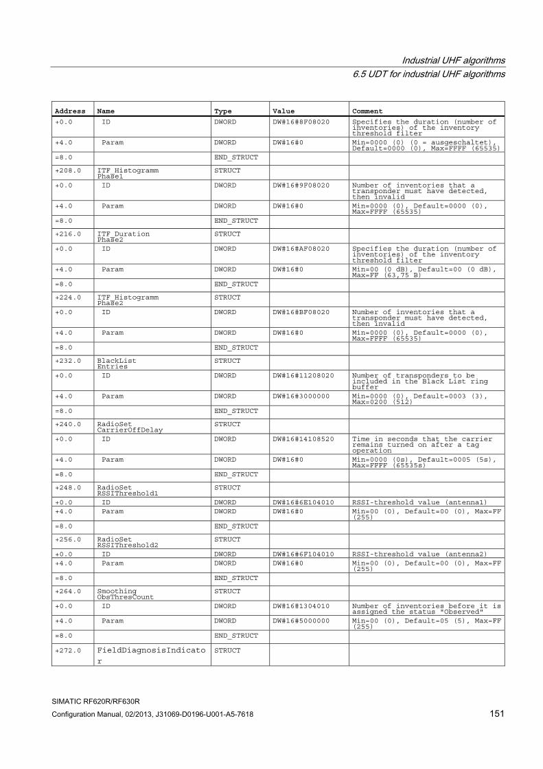
Industrial UHF algorithms 6.5 UDT for industrial UHF algorithms
SIMATIC RF620R/RF630R Configuration Manual, 02/2013, J31069-D0196-U001-A5-7618 151
Address Name Type Value Comment +0.0 ID DWORD DW#16#8F08020 Specifies the duration (number of
inventories) of the inventory threshold filter
+4.0 Param DWORD DW#16#0 Min=0000 (0) (0 = ausgeschaltet), Default=0000 (0), Max=FFFF (65535)
=8.0 END_STRUCT +208.0 ITF_Histogramm
Phase1 STRUCT
+0.0 ID DWORD DW#16#9F08020 Number of inventories that a transponder must have detected, then invalid
+4.0 Param DWORD DW#16#0 Min=0000 (0), Default=0000 (0), Max=FFFF (65535)
=8.0 END_STRUCT +216.0 ITF_Duration
Phase2 STRUCT +0.0 ID DWORD DW#16#AF08020 Specifies the duration (number of
inventories) of the inventory threshold filter
+4.0 Param DWORD DW#16#0 Min=00 (0 dB), Default=00 (0 dB), Max=FF (63,75 B)
=8.0 END_STRUCT +224.0 ITF_Histogramm
Phase2 STRUCT
+0.0 ID DWORD DW#16#BF08020 Number of inventories that a transponder must have detected, then invalid
+4.0 Param DWORD DW#16#0 Min=0000 (0), Default=0000 (0), Max=FFFF (65535)
=8.0 END_STRUCT +232.0 BlackList
Entries STRUCT
+0.0 ID DWORD DW#16#11208020 Number of transponders to be included in the Black List ring buffer
+4.0 Param DWORD DW#16#3000000 Min=0000 (0), Default=0003 (3), Max=0200 (512)
=8.0 END_STRUCT +240.0 RadioSet
CarrierOffDelay STRUCT +0.0 ID DWORD DW#16#14108520 Time in seconds that the carrier
remains turned on after a tag operation
+4.0 Param DWORD DW#16#0 Min=0000 (0s), Default=0005 (5s), Max=FFFF (65535s)
=8.0 END_STRUCT +248.0 RadioSet
RSSIThreshold1 STRUCT
+0.0 ID DWORD DW#16#6E104010 RSSI-threshold value (antenna1) +4.0 Param DWORD DW#16#0 Min=00 (0), Default=00 (0), Max=FF
(255) =8.0 END_STRUCT +256.0 RadioSet
RSSIThreshold2 STRUCT
+0.0 ID DWORD DW#16#6F104010 RSSI-threshold value (antenna2) +4.0 Param DWORD DW#16#0 Min=00 (0), Default=00 (0), Max=FF
(255) =8.0 END_STRUCT +264.0 Smoothing
ObsThresCount STRUCT
+0.0 ID DWORD DW#16#1304010 Number of inventories before it is assigned the status "Observed"
+4.0 Param DWORD DW#16#5000000 Min=00 (0), Default=05 (5), Max=FF (255)
=8.0 END_STRUCT +272.0 FieldDiagnosisIndicato
r
STRUCT
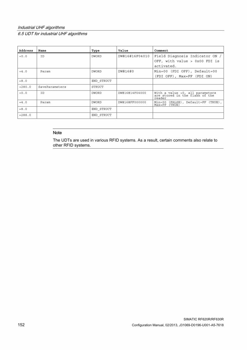
Industrial UHF algorithms 6.5 UDT for industrial UHF algorithms
SIMATIC RF620R/RF630R 152 Configuration Manual, 02/2013, J31069-D0196-U001-A5-7618
Address Name Type Value Comment +0.0 ID DWORD DW#16#16F04010 Field Diagnosis Indicator ON /
OFF, with value > 0x00 FDI is
activated.
+4.0 Param DWORD DW#16#0 Min=00 (FDI OFF), Default=00
(FDI OFF), Max=FF (FDI ON) =8.0 END_STRUCT +280.0 SaveParameters STRUCT +0.0 ID DWORD DW#16#14F04000 With a value >0, all parameters
are stored in the flash of the reader
+4.0 Param DWORD DW#16#FF000000 Min=00 (FALSE), Default=FF (TRUE), Max=FF (TRUE)
=8.0 END_STRUCT =288.0 END_STRUCT
Note
The UDTs are used in various RFID systems. As a result, certain comments also relate to other RFID systems.
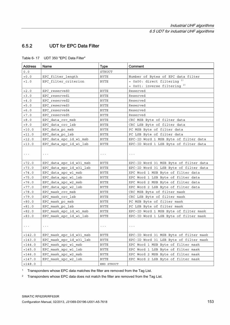
Industrial UHF algorithms 6.5 UDT for industrial UHF algorithms
SIMATIC RF620R/RF630R Configuration Manual, 02/2013, J31069-D0196-U001-A5-7618 153
6.5.2 UDT for EPC Data Filter
Table 6- 17 UDT 350 "EPC Data Filter"
Address Name Type Comment 0.0 STRUCT
+0.0 EPC_filter_length BYTE Number of Bytes of EPC data filter
+1.0 EPC_filter_criterion BYTE = 0x00: direct filtering 1)
= 0x01: inverse filtering 2)
+2.0 EPC_reserved0 BYTE Reserved
+3.0 EPC_reserved1 BYTE Reserved
+4.0 EPC_reserved2 BYTE Reserved
+5.0 EPC_reserved3 BYTE Reserved
+6.0 EPC_reserved4 BYTE Reserved
+7.0 EPC_reserved5 BYTE Reserved
+8.0 EPC_data_crc_msb BYTE CRC MSB Byte of filter data
+9.0 EPC_data_crc_lsb BYTE CRC LSB Byte of filter data
+10.0 EPC_data_pc_msb BYTE PC MSB Byte of filter data
+11.0 EPC_data_pc_lsb BYTE PC LSB Byte of filter data
+12.0 EPC_data_epc_id_w1_msb BYTE EPC-ID Word 1 MSB Byte of filter data
+13.0 EPC_data_epc_id_w1_lsb BYTE EPC-ID Word 1 LSB Byte of filter data
...
...
...
...
+72.0 EPC_data_epc_id_w31_msb BYTE EPC-ID Word 31 MSB Byte of filter data
+73.0 EPC_data_epc_id_w31_lsb BYTE EPC-ID Word 31 LSB Byte of filter data
+74.0 EPC_data_xpc_w1_msb BYTE XPC Word 1 MSB Byte of filter data
+75.0 EPC_data_xpc_w1_lsb BYTE XPC Word 1 LSB Byte of filter data
+76.0 EPC_data_xpc_w2_msb BYTE XPC Word 2 MSB Byte of filter data
+77.0 EPC_data_xpc_w2_lsb BYTE XPC Word 2 LSB Byte of filter data
+78.0 EPC_mask_crc_msb BYTE CRC MSB Byte of filter mask
+79.0 EPC_mask_crc_lsb BYTE CRC LSB Byte of filter mask
+80.0 EPC_mask_pc_msb BYTE PC MSB Byte of filter mask
+81.0 EPC_mask_pc_lsb BYTE PC LSB Byte of filter mask
+82.0 EPC_mask_epc_id_w1_msb BYTE EPC-ID Word 1 MSB Byte of filter mask
+83.0 EPC_mask_epc_id_w1_lsb BYTE EPC-ID Word 1 LSB Byte of filter mask
...
...
...
...
+142.0 EPC_mask_epc_id_w31_msb BYTE EPC-ID Word 31 MSB Byte of filter mask
+143.0 EPC_mask_epc_id_w31_lsb BYTE EPC-ID Word 31 LSB Byte of filter mask
+144.0 EPC_mask_xpc_w1_msb BYTE XPC Word 1 MSB Byte of filter mask
+145.0 EPC_mask_xpc_w1_lsb BYTE XPC Word 1 LSB Byte of filter mask
+146.0 EPC_mask_xpc_w2_msb BYTE XPC Word 2 MSB Byte of filter mask
+147.0 EPC_mask_xpc_w2_lsb BYTE XPC Word 2 LSB Byte of filter mask
=148.0 END STRUCT
1 Transponders whose EPC data matches the filter are removed from the Tag List. 2 Transponders whose EPC data does not match the filter are removed from the Tag List.
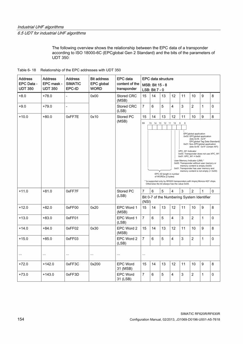
Industrial UHF algorithms 6.5 UDT for industrial UHF algorithms
SIMATIC RF620R/RF630R 154 Configuration Manual, 02/2013, J31069-D0196-U001-A5-7618
The following overview shows the relationship between the EPC data of a transponder according to ISO 18000-6C (EPCglobal Gen 2 Standard) and the bits of the parameters of UDT 350:
Table 6- 18 Relationship of the EPC addresses with UDT 350
Address EPC Data - UDT 350
Address EPC mask - UDT 350
Address SIMATIC EPC-ID
Bit address EPC global WORD
EPC data content of the transponder
EPC data structure MSB: Bit 15 - 8 LSB: Bit 7 - 0
+8.0 +78.0 - Stored CRC (MSB)
15 14 13 12 11 10 9 8
+9.0 +79.0 -
0x00
Stored CRC (LSB)
7 6 5 4 3 2 1 0
15 14 13 12 11 10 9 8 +10.0 +80.0 0xFF7E Stored PC (MSB)
7 6 5 4 3 2 1 0 +11.0 +81.0 0xFF7F
0x10
Stored PC (LSB) Bit 0-7 of the Numbering System Identifier
(NSI) +12.0 +82.0 0xFF00 EPC Word 1
(MSB) 15 14 13 12 11 10 9 8
+13.0 +83.0 0xFF01
0x20
EPC Word 1 (LSB)
7 6 5 4 3 2 1 0
+14.0 +84.0 0xFF02 EPC Word 2 (MSB)
15 14 13 12 11 10 9 8
+15.0 +85.0 0xFF03
0x30
EPC Word 2 (LSB)
7 6 5 4 3 2 1 0
...
...
...
...
...
...
+72.0 +142.0 0xFF3C EPC Word 31 (MSB)
15 14 13 12 11 10 9 8
+73.0 +143.0 0xFF3D
0x200
EPC Word 31 (LSB)
7 6 5 4 3 2 1 0
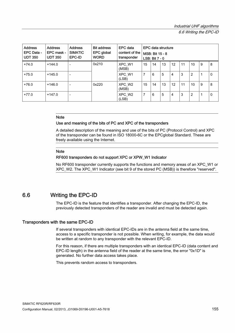
Industrial UHF algorithms 6.6 Writing the EPC-ID
SIMATIC RF620R/RF630R Configuration Manual, 02/2013, J31069-D0196-U001-A5-7618 155
Address EPC Data - UDT 350
Address EPC mask - UDT 350
Address SIMATIC EPC-ID
Bit address EPC global WORD
EPC data content of the transponder
EPC data structure MSB: Bit 15 - 8 LSB: Bit 7 - 0
+74.0 +144.0 - XPC_W1 (MSB)
15 14 13 12 11 10 9 8
+75.0 +145.0 -
0x210
XPC_W1 (LSB)
7 6 5 4 3 2 1 0
+76.0 +146.0 - XPC_W2 (MSB)
15 14 13 12 11 10 9 8
+77.0 +147.0 -
0x220
XPC_W2 (LSB)
7 6 5 4 3 2 1 0
Note Use and meaning of the bits of PC and XPC of the transponders
A detailed description of the meaning and use of the bits of PC (Protocol Control) and XPC of the transponder can be found in ISO 18000-6C or the EPCglobal Standard. These are freely available using the Internet.
Note RF600 transponders do not support XPC or XPW_W1 Indicator
No RF600 transponder currently supports the functions and memory areas of an XPC_W1 or XPC_W2. The XPC_W1 Indicator (see bit 9 of the stored PC (MSB)) is therefore "reserved".
6.6 Writing the EPC-ID The EPC-ID is the feature that identifies a transponder. After changing the EPC-ID, the previously detected transponders of the reader are invalid and must be detected again.
Transponders with the same EPC-ID If several transponders with identical EPC-IDs are in the antenna field at the same time, access to a specific transponder is not possible. When writing, for example, the data would be written at random to any transponder with the relevant EPC-ID.
For this reason, if there are multiple transponders with an identical EPC-ID (data content and EPC-ID length) in the antenna field of the reader at the same time, the error "0x1D" is generated. No further data access takes place.
This prevents random access to transponders.
Industrial UHF algorithms 6.6 Writing the EPC-ID
SIMATIC RF620R/RF630R 156 Configuration Manual, 02/2013, J31069-D0196-U001-A5-7618
Assigning different EPC-IDs The SIMATIC RF600 industrial transponders always have different EPC-IDs when they are supplied and can normally be used immediately. The SIMATIC RF600 labels (e.g. RF630L), on the other hand, all have the same EPC-ID.
Bring one RF630L separately into the antenna field and assign its special EPC-ID with a "WRITE" command.
Writing EPC-IDs The write command to address FF00 allows the EPC-ID memory bank to be written to and the content but not the length of the EPC-ID can be changed. To be able to define an EPC-ID with a different length (2 - 62 bytes), a write command to address "FEFE" is necessary. The maximum length of the EPC-ID is restricted by the transponder hardware and depends on the transponder type being used.
Note Structure of the EPC-ID
The data content of the write command consists of 2 bytes EPC-ID length + n bytes data content (EPC-ID). This data content is transferred to address "FEFE" on the transponder with a write command. The length of the EPC-ID must always be even.
Example:
A 6 byte long EPC-ID ("00 06") with EPC-ID ("010203040506") will be written to the transponder.
In this case write the data "00 06 01 02 03 04 05 06".
Note Behavior of the display "ANZ_MDS_present" when writing a new EPC-ID to a transponder
After changing the EPC-ID of a transponder, the present status is briefly deleted ("ANZ_MDS_present = 0"). After a successful inventory of the transponder with the newly assigned EPC-ID, the present status is set again.
A handle ID assigned to a transponder before writing the EPC-ID is therefore invalid after changing the EPC-ID. After changing the EPC-ID, a new handle ID is assigned to the transponder by the inventory.
You should therefore take this process of switching the bit off and on into consideration if "ANZ_MDS_present" is evaluated in the user program.
You will find more detailed information on writing the MOBY_mode = 6 using the UID in the section "UID (Page 59)".
Industrial UHF algorithms 6.7 Special functions of the RF600 transponders
SIMATIC RF620R/RF630R Configuration Manual, 02/2013, J31069-D0196-U001-A5-7618 157
6.7 Special functions of the RF600 transponders This section introduces you to the password, LOCK and KILL functions of the EPC transponder. You will find detailed information specifically about the use of these functions in a SIMATIC environment. You will find a detailed description of all EPC functions in the standard ISO 18000-6C.
6.7.1 Setting passwords and erasing them again
Function of the passwords For write and read commands, the password protection provided by the air interface standard EPC Class 1 Gen 2 (ISO 18 000-6C) is used.
A 4-byte long ACCESS and KILL password is provided for each individual transponder. Each password is considered undefined as long as it has the value 0. A password is considered defined once a value > 0 has been written to the transponder.
ACCESS and KILL password The ACCESS password can be used to restrict access to the memory banks (USER-Memory, EPC-MemBank and TID-MemBank) of the relevant transponder.
The KILL password serves as protection and prevents accidental permanent deactivation of a transponder. When supplied, the SIMATIC RF630L, for example, has the "KILL" password = 0, that prevents it from being deactivated in its default status. The RFID label is made permanently unusable only after a KILL password has been written and a KILL command executed.
The ACCESS password and the KILL password are stored in the "RESERVED" memory bank of the transponder. There you can read them out, delete them and set them again.
In the SIMATIC controller, the following password address assignments apply:
● KILL password: Address FF80; length 4 bytes on the transponder
● ACCESS password: Address FF84; length 4 bytes on the transponder
● KILL password: Address FFFF; length 4 bytes on the reader; write-only; also executes the KILL function of the transponder at the same time
● ACCESS password: Address FFFD; length 4 bytes on the reader; write-only
Industrial UHF algorithms 6.7 Special functions of the RF600 transponders
SIMATIC RF620R/RF630R 158 Configuration Manual, 02/2013, J31069-D0196-U001-A5-7618
The following rules apply to passwords:
● Passwords can be written and read normally if they are in the UNLOCK status.
● After the LOCK , passwords can only be changed using the ACCESS password.
● After the Perma-LOCK of the "RESERVED" memory bank, passwords are permanently set.
Note Using passwords • As long as no ACCESS password has been stored on the transponder (as shipped:
ACCESS password = 0), you can write to the user area of the transponder without any restriction.
• If no ACCESS password has been stored on the transponder and an ACCESS password has been saved on the reader, you cannot write to the transponder in the UNLOCK status. An error message is issued.
• The various passwords are saved using the "WRITE" command at default addresses on the transponder or on the reader. On the reader, the password is lost after it is turned off.
• After you have written a password to the transponder, you must transfer this password to the reader with each subsequent "WRITE/READ/INIT" command. For read or write access to the transponder, the password transferred to the reader must be identical to the password stored on the transponder.
• The LOCK function protects a memory area on the transponder from being overwritten or deleted.
• A KILL function cannot execute on the transponder unless you have stored a KILL password on the transponder. After you have saved a KILL password on the transponder, you can execute the KILL function and make the transponder unusable.
• If you switch off the supply voltage on the reader or send an "init_run" command to the reader, the password on the reader (ACCESS password, KILL password) will be deleted, in other words, set to 0.
• Transponders with different passwords can therefore only be read if the password assigned to the transporter is set on the reader prior to the read.
Industrial UHF algorithms 6.7 Special functions of the RF600 transponders
SIMATIC RF620R/RF630R Configuration Manual, 02/2013, J31069-D0196-U001-A5-7618 159
6.7.2 Application of the LOCK function Transponders that are operated via the air interface protocol EPC Class 1 Gen 2 or ISO 18000-6C can be temporarily or permanently locked or even unlocked for read and write access.
Using the LOCK functions you can block or permit write access for each transponder memory bank.
Set the corresponding access rights separately for each of the memory banks and each password.
Note Transponder can become unusable
Only use the LOCK and password functions when you are sure what you want to achieve. If these functions are handled incorrectly, the transponder may become permanently unusable for your application
The following applies: After you have written a password to the transponder, make sure that this password is stored on the reader each time the "WRITE/READ/INIT" command is used later. For read or write access to the transponder, the password transferred to the reader must be identical to the password stored on the transponder.
The LOCK function is implemented using the SIMATIC "WRITE" command. With this "WRITE" command, the following information is always transferred:
● Address [hex] "FF FE"
● The length of the data must always be 3 bytes
● Codings for the "LOCK" function (see section "Codes for the LOCK function (Page 161)")
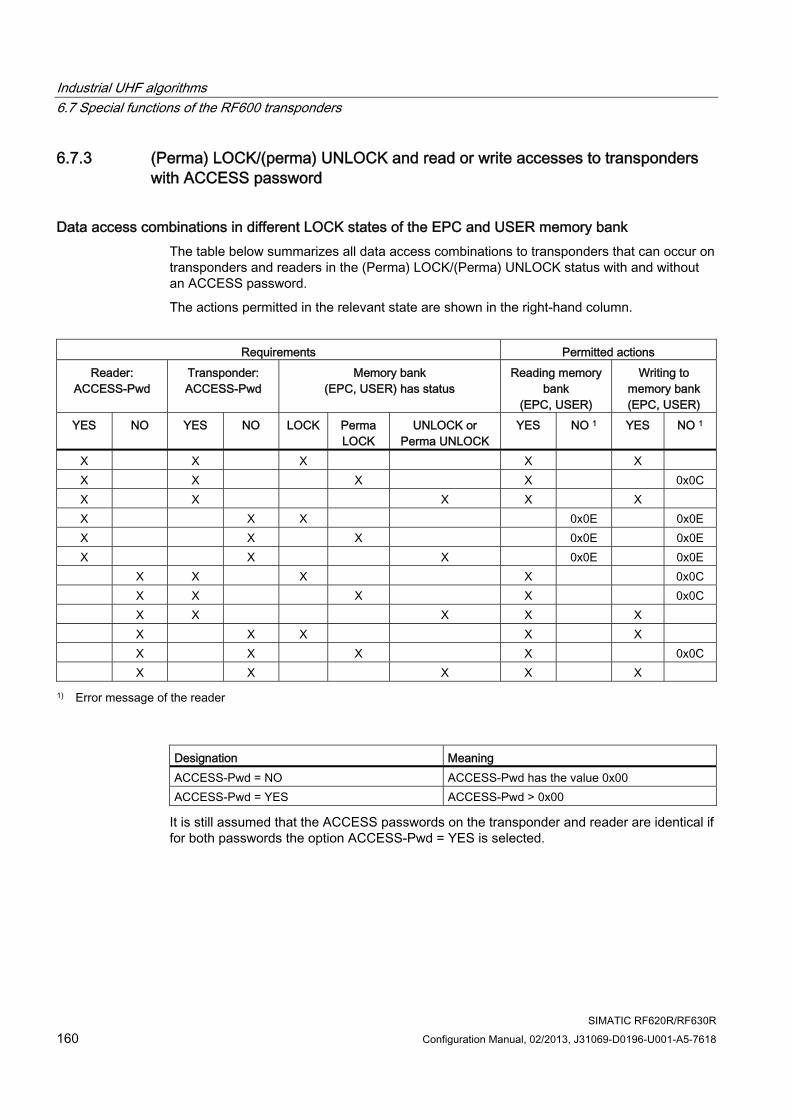
Industrial UHF algorithms 6.7 Special functions of the RF600 transponders
SIMATIC RF620R/RF630R 160 Configuration Manual, 02/2013, J31069-D0196-U001-A5-7618
6.7.3 (Perma) LOCK/(perma) UNLOCK and read or write accesses to transponders with ACCESS password
Data access combinations in different LOCK states of the EPC and USER memory bank The table below summarizes all data access combinations to transponders that can occur on transponders and readers in the (Perma) LOCK/(Perma) UNLOCK status with and without an ACCESS password.
The actions permitted in the relevant state are shown in the right-hand column.
Requirements Permitted actions
Reader: ACCESS-Pwd
Transponder: ACCESS-Pwd
Memory bank (EPC, USER) has status
Reading memory bank
(EPC, USER)
Writing to memory bank (EPC, USER)
YES NO YES NO LOCK Perma LOCK
UNLOCK or Perma UNLOCK
YES NO 1 YES NO 1
X X X X X X X X X 0x0C X X X X X X X X 0x0E 0x0E X X X 0x0E 0x0E X X X 0x0E 0x0E X X X X 0x0C X X X X 0x0C X X X X X X X X X X X X X X 0x0C X X X X X
1) Error message of the reader
Designation Meaning ACCESS-Pwd = NO ACCESS-Pwd has the value 0x00 ACCESS-Pwd = YES ACCESS-Pwd > 0x00
It is still assumed that the ACCESS passwords on the transponder and reader are identical if for both passwords the option ACCESS-Pwd = YES is selected.
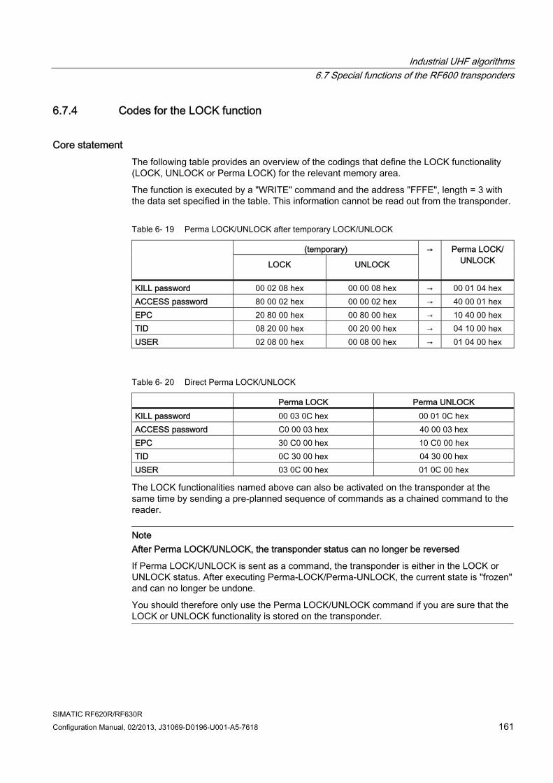
Industrial UHF algorithms 6.7 Special functions of the RF600 transponders
SIMATIC RF620R/RF630R Configuration Manual, 02/2013, J31069-D0196-U001-A5-7618 161
6.7.4 Codes for the LOCK function
Core statement The following table provides an overview of the codings that define the LOCK functionality (LOCK, UNLOCK or Perma LOCK) for the relevant memory area.
The function is executed by a "WRITE" command and the address "FFFE", length = 3 with the data set specified in the table. This information cannot be read out from the transponder.
Table 6- 19 Perma LOCK/UNLOCK after temporary LOCK/UNLOCK
(temporary)
LOCK UNLOCK
→ Perma LOCK/ UNLOCK
KILL password 00 02 08 hex 00 00 08 hex → 00 01 04 hex ACCESS password 80 00 02 hex 00 00 02 hex → 40 00 01 hex EPC 20 80 00 hex 00 80 00 hex → 10 40 00 hex TID 08 20 00 hex 00 20 00 hex → 04 10 00 hex USER 02 08 00 hex 00 08 00 hex → 01 04 00 hex
Table 6- 20 Direct Perma LOCK/UNLOCK
Perma LOCK Perma UNLOCK KILL password 00 03 0C hex 00 01 0C hex ACCESS password C0 00 03 hex 40 00 03 hex EPC 30 C0 00 hex 10 C0 00 hex TID 0C 30 00 hex 04 30 00 hex USER 03 0C 00 hex 01 0C 00 hex
The LOCK functionalities named above can also be activated on the transponder at the same time by sending a pre-planned sequence of commands as a chained command to the reader.
Note After Perma LOCK/UNLOCK, the transponder status can no longer be reversed
If Perma LOCK/UNLOCK is sent as a command, the transponder is either in the LOCK or UNLOCK status. After executing Perma-LOCK/Perma-UNLOCK, the current state is "frozen" and can no longer be undone.
You should therefore only use the Perma LOCK/UNLOCK command if you are sure that the LOCK or UNLOCK functionality is stored on the transponder.
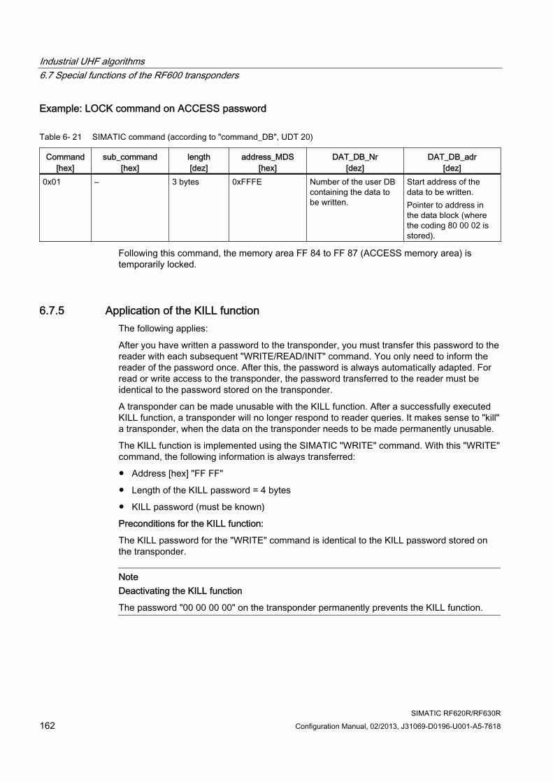
Industrial UHF algorithms 6.7 Special functions of the RF600 transponders
SIMATIC RF620R/RF630R 162 Configuration Manual, 02/2013, J31069-D0196-U001-A5-7618
Example: LOCK command on ACCESS password
Table 6- 21 SIMATIC command (according to "command_DB", UDT 20)
Command [hex]
sub_command [hex]
length [dez]
address_MDS [hex]
DAT_DB_Nr [dez]
DAT_DB_adr [dez]
0x01 – 3 bytes 0xFFFE Number of the user DB containing the data to be written.
Start address of the data to be written. Pointer to address in the data block (where the coding 80 00 02 is stored).
Following this command, the memory area FF 84 to FF 87 (ACCESS memory area) is temporarily locked.
6.7.5 Application of the KILL function The following applies:
After you have written a password to the transponder, you must transfer this password to the reader with each subsequent "WRITE/READ/INIT" command. You only need to inform the reader of the password once. After this, the password is always automatically adapted. For read or write access to the transponder, the password transferred to the reader must be identical to the password stored on the transponder.
A transponder can be made unusable with the KILL function. After a successfully executed KILL function, a transponder will no longer respond to reader queries. It makes sense to "kill" a transponder, when the data on the transponder needs to be made permanently unusable.
The KILL function is implemented using the SIMATIC "WRITE" command. With this "WRITE" command, the following information is always transferred:
● Address [hex] "FF FF"
● Length of the KILL password = 4 bytes
● KILL password (must be known)
Preconditions for the KILL function:
The KILL password for the "WRITE" command is identical to the KILL password stored on the transponder.
Note Deactivating the KILL function
The password "00 00 00 00" on the transponder permanently prevents the KILL function.
Industrial UHF algorithms 6.8 Command repetition and ScanningMode
SIMATIC RF620R/RF630R Configuration Manual, 02/2013, J31069-D0196-U001-A5-7618 163
6.8 Command repetition and ScanningMode
Definition of terms The terms "command repetition", "ScanningMode" and "unspecified read commands" are closely associated with each other. The following definitions of the terms are intended to help you to understand the methods and their uses.
● Command repetition
Command repetition is a sequence of commands that runs automatically on the reader that is used with each new transponder.
In the simple mode (ScanningMode is deactivated) command repetition operates in applications in which the transponders are read singly one after the other. This means that only one transponder is permitted in the antenna field at any one time.
● ScanningMode
The ScanningMode is a special form of command repetition. In contrast to command repetition without ScanningMode , the ScanningMode can be used with any transponder population. This means that the ScanningMode is only available when working with FB 55 (MOBY_mode = 6, 7).
● Unspecified read command
An unspecified read command is a read command with which the UID is specified with the value = 0 (4 bytes with MOBY_mode = 6 and 8 bytes with MOBY_mode = 7). This makes it possible to access a transponder with any EPC-ID without the EPC-ID being known in advance.
You will find more detailed information in the section "UID (Page 59)".
6.8.1 Command repetition
Operating principle After a restart (or "init_run") of the reader, the FB 45/ FB 55 transfers the command (or command chain) once to the CM/reader. Command transmission is automatic with the first "command_start". This command (or the last command or the command chain) always remains intermediately stored in the reader. If command repetition is started now, the temporarily stored command on the reader is executed again, and the result(s) transferred to FB 45 / FB 55.
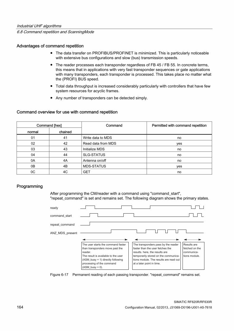
Industrial UHF algorithms 6.8 Command repetition and ScanningMode
SIMATIC RF620R/RF630R 164 Configuration Manual, 02/2013, J31069-D0196-U001-A5-7618
Advantages of command repetition ● The data transfer on PROFIBUS/PROFINET is minimized. This is particularly noticeable
with extensive bus configurations and slow (bus) transmission speeds.
● The reader processes each transponder regardless of FB 45 / FB 55. In concrete terms, this means that in applications with very fast transponder sequences or gate applications with many transponders, each transponder is processed. This takes place no matter what the (PROFI) BUS speed.
● Total data throughput is increased considerably particularly with controllers that have few system resources for acyclic frames.
● Any number of transponders can be detected simply.
Command overview for use with command repetition
Command [hex]
normal chained
Command Permitted with command repetition
01 41 Write data to MDS no 02 42 Read data from MDS yes 03 43 Initialize MDS no 04 44 SLG-STATUS no 0A 4A Antenna on/off no 0B 4B MDS-STATUS yes 0C 4C GET no
Programming After programming the CM/reader with a command using "command_start", "repeat_command" is set and remains set. The following diagram shows the primary states.
Figure 6-17 Permanent reading of each passing transponder. "repeat_command" remains set.
Industrial UHF algorithms 6.8 Command repetition and ScanningMode
SIMATIC RF620R/RF630R Configuration Manual, 02/2013, J31069-D0196-U001-A5-7618 165
Further results can be read out with "command_start" and "ready". In this mode, new commands are always started with "command_start". This means that the results are available very quickly.
When permanent command repetition is used, data may be transferred to the FB slower than new transponders are being processed (fast transponder sequence, slow data transfer). In this case, the results are temporarily stored on the CM. The CM or reader has a number of buffers for this intermediate storage. If the buffers are full because the FB has not fetched data and additional transponders arrive, these transponders are no longer processed.
Table 6- 22 Readers and communications modules that support command repetition
Device type Number of buffers (number of commands)
Max. user data that can be processed with command repetition
RF620R RF630R
150 150
233 bytes × 150 = 34 950 bytes 233 bytes × 150 = 34 950 bytes
RF170C RF180C ASM 456 ASM 475
150 150 150 70
233 bytes × 150 = 34 950 bytes 233 bytes × 150 = 34 950 bytes 233 bytes × 150 = 34 950 bytes 233 bytes × 70 = 16 310 bytes
6.8.2 Enabling the ScanningMode The ScanningMode is always prepared with "init_run" on the reader. The ScanningMode is assigned parameters by setting bit 6 in the "field_ON_control" variable of FB 55.
Subsequent activation of the ScanningMode is achieved by starting command repetition with "command_start" and "repeat_command".
Benefits and drawbacks of ScanningMode
● The ScanningMode processes any number of transponders very quickly and is uncomplicated. This makes bulk reading at gates very simple.
● In ScanningMode , no error messages are output if the processing of a transponder is not completed correctly. The transponders affected do not appear in the results list.
Sequence of the ScanningMode 1. Preparation of the ScanningMode by setting bit 6 = 1.
2. Command chains of unspecific read commands are then used with all transponders located in the antenna field.
Deactivation of the ScanningMode by setting bit 6 = 0.
Industrial UHF algorithms 6.8 Command repetition and ScanningMode
SIMATIC RF620R/RF630R 166 Configuration Manual, 02/2013, J31069-D0196-U001-A5-7618
Setting bit 6 = 1 followed by "init_run" - ScanningMode prepared Sending an unspecified read command or a chain of unspecified read commands
- ScanningMode prepared
Setting the control bit "repeat_command" - ScanningMode is activated Optional: Resetting the control bit "repeat_command"
- ScanningMode prepared
In this mode, the reader uses the read command or chained read commands for all transponders in the Tag List in sequence and reads out their data.
6.8.3 Operating conditions ● Logging in the Tag List
The Tag List logs the transponders for which an unspecified read command or a chain of unspecified read commands was completed successfully. The next time the Tag List is run through with "repeat_command", this unspecified read command or this chain of unspecified read commands is not sent to the transponder again (with this unique EPC-ID).
● Initial reader status or "repeat_command = OFF" (only after "repeat_command = ON")
If an unspecified read command or a chain of unspecified read commands is sent, then the read command or the entire chain of read commands relates to the first transponder in a Tag List. As a result of repeated sending of an unspecified read command or chain of unspecified read commands, the commands always relate to the first transponder in the current Tag List .
● "repeat_command = ON"
An unspecified read command or a chain of unspecified read commands is only used with all transponders in a Tag List when there is a "repeat_command = ON" following an unspecified read command or a chain of unspecified read commands. When command repetition is started, the first transponder is not processed again after it has been processed once.
● Read result with a command chain
The reader only returns the complete result of a command chain when this has been executed completely and correctly. If the reader finds an error within a chain, all previous partial results are discarded. This means that the user does not receive a result for this transponder.
Industrial UHF algorithms 6.8 Command repetition and ScanningMode
SIMATIC RF620R/RF630R Configuration Manual, 02/2013, J31069-D0196-U001-A5-7618 167
● Aborting of command repetition
If a command chain with "repeat_command = ON" is identified as being a correct sequence of commands the first time it is run through, command repetition can only be stopped in the following ways:
– Sending an "init_run" or
– "repeat_command = OFF"
If execution of a chain has already started before the "repeat_command = OFF" is received, this will be completed and, if applicable, acknowledged. Only then will the reader send "command_rep_active = 0".
● Activating command repetition again
After deactivating the command repetition and reactivating it again, the last pending unspecified command or unspecified chain of commands is used again for the current Tag List .
6.8.4 Errors and special cases
Error when reading within a chain
As soon as an error occurs within a valid chain of unspecified read commands, the remaining read commands in the chain will be canceled for the transponder (Tag List) currently due to be processed, and the chain will be applied to the next tag in the Tag List.
Display of read errors on the reader
As described in the previous paragraph, error messages in ScanningMode are not forwarded to the function block. Nevertheless, the red LED on the reader makes it possible to see that the reader has not been able to execute a command properly. In this case, the LED on the reader lights up red for a certain time (see section Error messages and flashing codes (Page 84)).
Error in the command chain
Write commands, incorrect command formats etc. are identified as errors the first time a chain is run through and are output as an error message. Any set "repeat_command" is ignored.
Use of passwords
If you want to use passwords for access to transponders, make sure that the same password is are used for all transponders in the antenna field and stored and used appropriately on the reader.
Several transponders with identical EPC-IDs in the antenna field
If several tags with identical EPC-IDs are present in the antenna field of the reader, data is not returned by any of these transponders.
Industrial UHF algorithms 6.9 Transmit / radiated power setting
SIMATIC RF620R/RF630R 168 Configuration Manual, 02/2013, J31069-D0196-U001-A5-7618
6.9 Transmit / radiated power setting The transmit power is set on the RF630R reader. On the RF620R reader, you can set the radiated power directly using the "distance_limiting" parameter. The transmit power is the power transmitted at the reader output, the radiated power is the power radiated by an antenna.
Because the RF620R reader has an integrated antenna, in contrast to the RF630R reader, the cable attenuation and antenna gain cannot be adjusted. You can influence the radiated power of the antenna connected to the RF630R with the following parameters: Cable attenuation, antenna gain, transmit power of the reader.
You can find out the radiated power needed to meet your requirements using the "Tool for calculating the radiated power(RF600) (http://support.automation.siemens.com/WW/view/en/59585543)" tool.
SIMATIC RF620R/RF630R Configuration Manual, 02/2013, J31069-D0196-U001-A5-7618 169
Appendix AA.1 Differences between SIMATIC command level and message frame
level The parameters for the RF600 readers can be set in two ways:
● using SIMATIC commands of FB 45 and FB 55
● using a customer-specific PC program that sends the command frames directly for the reader
Since parameter assignment using function blocks FB 45 and FB 55 is the standard method, this method will be described in detail.
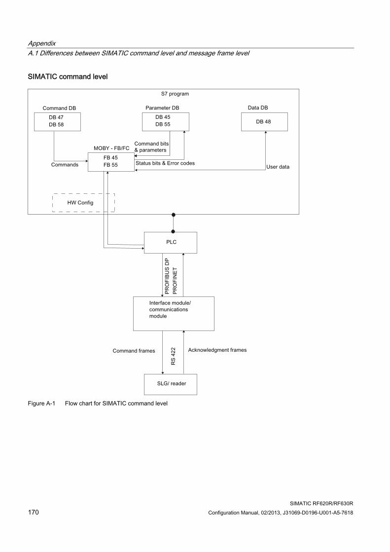
Appendix A.1 Differences between SIMATIC command level and message frame level
SIMATIC RF620R/RF630R 170 Configuration Manual, 02/2013, J31069-D0196-U001-A5-7618
SIMATIC command level
Figure A-1 Flow chart for SIMATIC command level
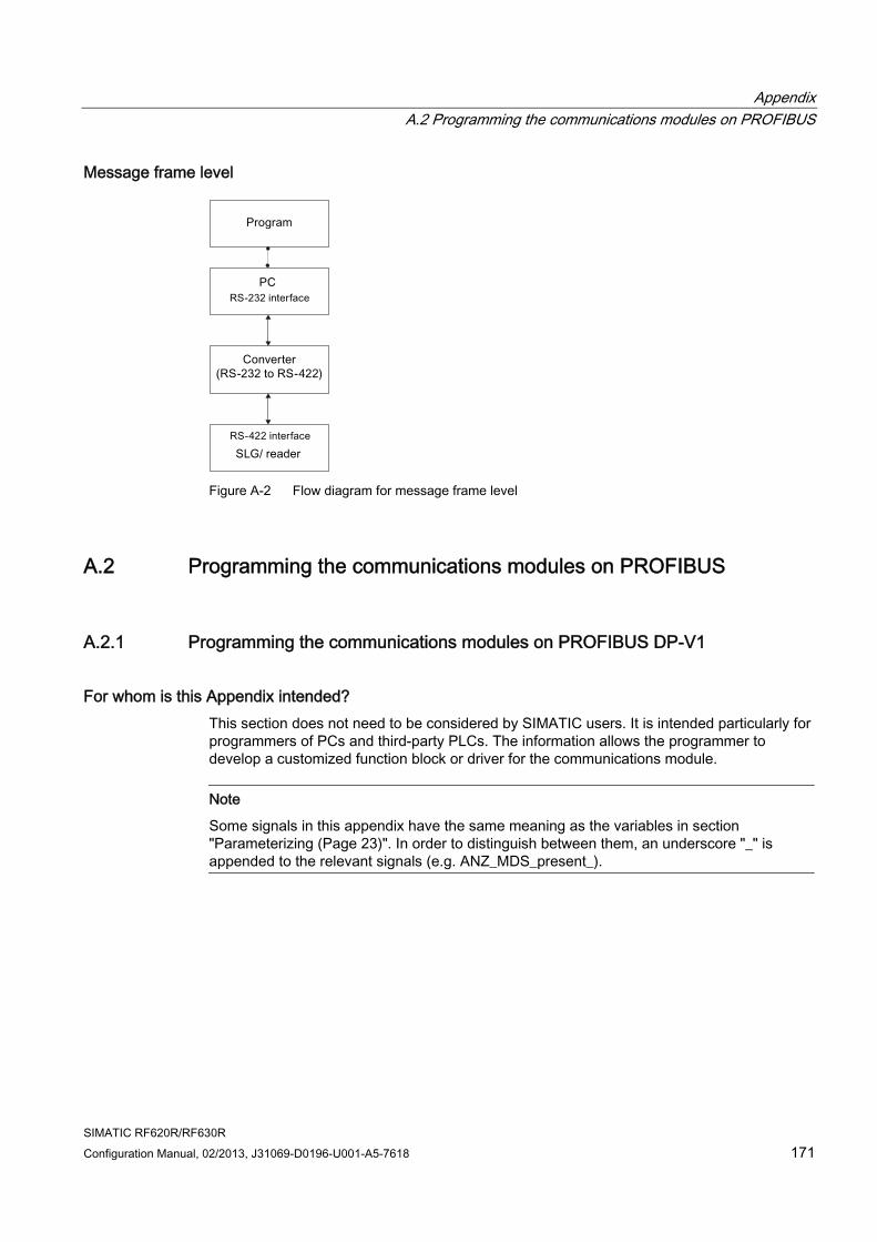
Appendix A.2 Programming the communications modules on PROFIBUS
SIMATIC RF620R/RF630R Configuration Manual, 02/2013, J31069-D0196-U001-A5-7618 171
Message frame level
Figure A-2 Flow diagram for message frame level
A.2 Programming the communications modules on PROFIBUS
A.2.1 Programming the communications modules on PROFIBUS DP-V1
For whom is this Appendix intended? This section does not need to be considered by SIMATIC users. It is intended particularly for programmers of PCs and third-party PLCs. The information allows the programmer to develop a customized function block or driver for the communications module.
Note
Some signals in this appendix have the same meaning as the variables in section "Parameterizing (Page 23)". In order to distinguish between them, an underscore "_" is appended to the relevant signals (e.g. ANZ_MDS_present_).
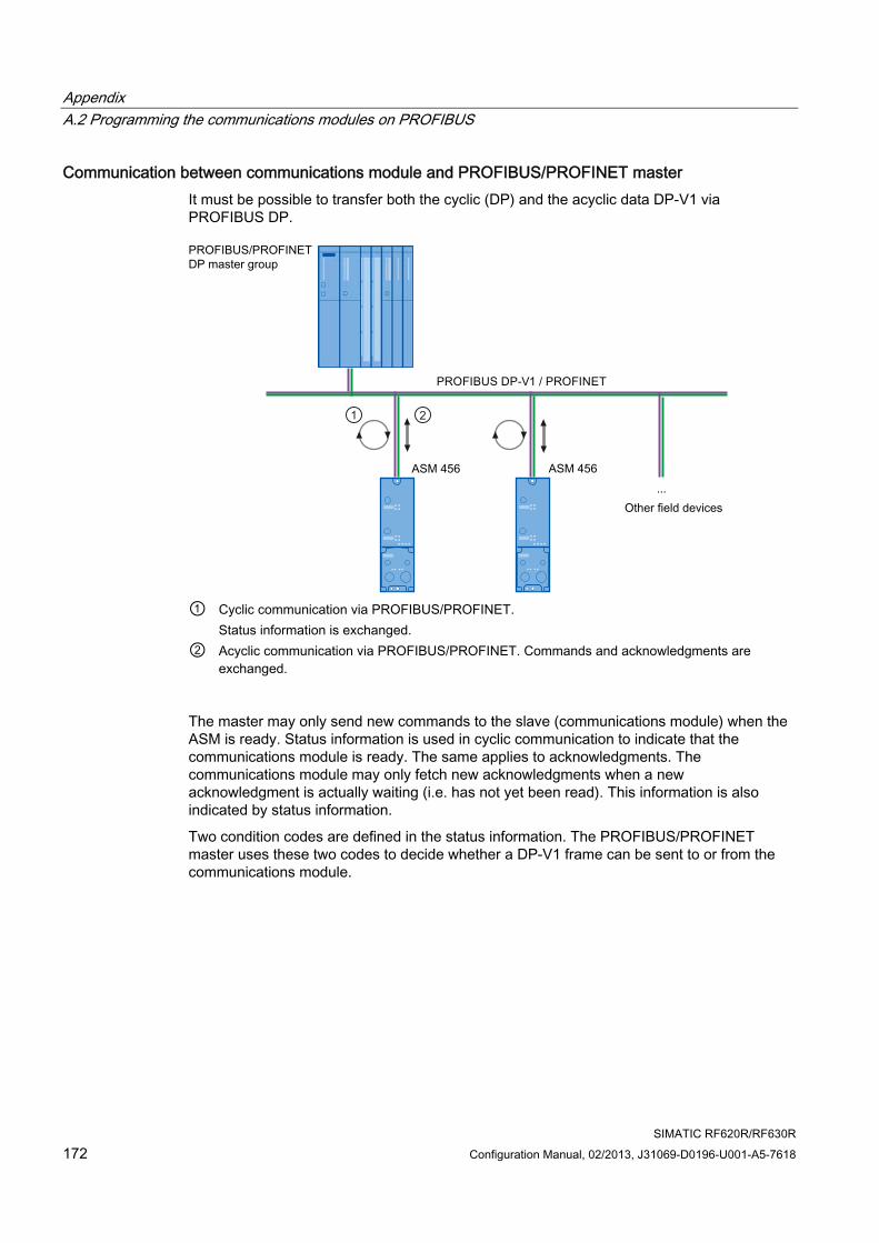
Appendix A.2 Programming the communications modules on PROFIBUS
SIMATIC RF620R/RF630R 172 Configuration Manual, 02/2013, J31069-D0196-U001-A5-7618
Communication between communications module and PROFIBUS/PROFINET master It must be possible to transfer both the cyclic (DP) and the acyclic data DP-V1 via PROFIBUS DP.
① Cyclic communication via PROFIBUS/PROFINET.
Status information is exchanged. ② Acyclic communication via PROFIBUS/PROFINET. Commands and acknowledgments are
exchanged.
The master may only send new commands to the slave (communications module) when the ASM is ready. Status information is used in cyclic communication to indicate that the communications module is ready. The same applies to acknowledgments. The communications module may only fetch new acknowledgments when a new acknowledgment is actually waiting (i.e. has not yet been read). This information is also indicated by status information.
Two condition codes are defined in the status information. The PROFIBUS/PROFINET master uses these two codes to decide whether a DP-V1 frame can be sent to or from the communications module.
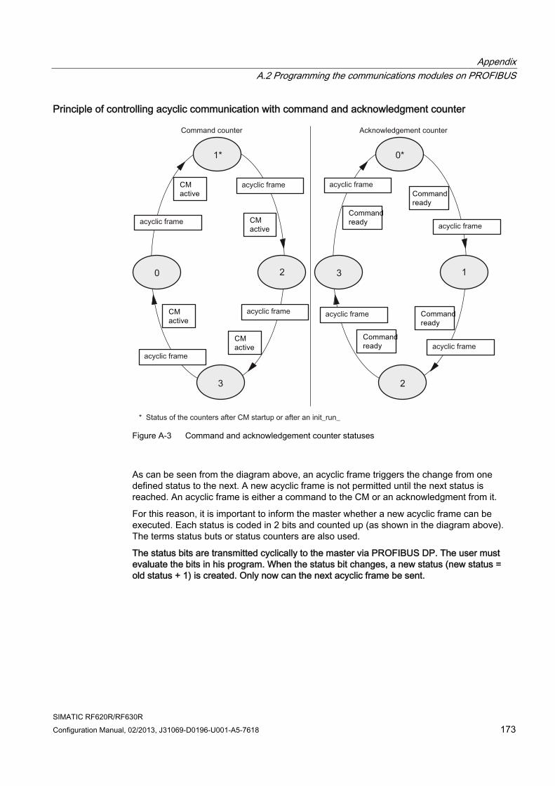
Appendix A.2 Programming the communications modules on PROFIBUS
SIMATIC RF620R/RF630R Configuration Manual, 02/2013, J31069-D0196-U001-A5-7618 173
Principle of controlling acyclic communication with command and acknowledgment counter
Figure A-3 Command and acknowledgement counter statuses
As can be seen from the diagram above, an acyclic frame triggers the change from one defined status to the next. A new acyclic frame is not permitted until the next status is reached. An acyclic frame is either a command to the CM or an acknowledgment from it.
For this reason, it is important to inform the master whether a new acyclic frame can be executed. Each status is coded in 2 bits and counted up (as shown in the diagram above). The terms status buts or status counters are also used.
The status bits are transmitted cyclically to the master via PROFIBUS DP. The user must evaluate the bits in his program. When the status bit changes, a new status (new status = old status + 1) is created. Only now can the next acyclic frame be sent.
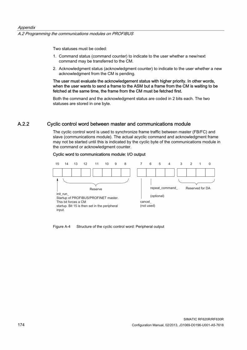
Appendix A.2 Programming the communications modules on PROFIBUS
SIMATIC RF620R/RF630R 174 Configuration Manual, 02/2013, J31069-D0196-U001-A5-7618
Two statuses must be coded:
1. Command status (command counter) to indicate to the user whether a new/next command may be transferred to the CM.
2. Acknowledgment status (acknowledgment counter) to indicate to the user whether a new acknowledgment from the CM is pending.
The user must evaluate the acknowledgement status with higher priority. In other words, when the user wants to send a frame to the ASM but a frame from the CM is waiting to be fetched at the same time, the frame from the CM must be fetched first.
Both the command and the acknowledgment status are coded in 2 bits each. The two statuses are stored in one byte.
A.2.2 Cyclic control word between master and communications module The cyclic control word is used to synchronize frame traffic between master (FB/FC) and slave (communications module). The actual acyclic command and acknowledgment frame may not be started until this is indicated by the cyclic byte of the communications module in the command or acknowledgment counter.
Cyclic word to communications module: I/O output
Figure A-4 Structure of the cyclic control word: Peripheral output
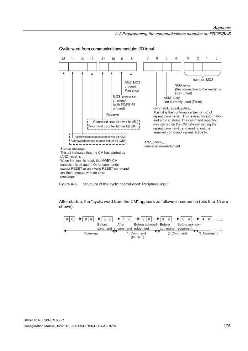
Appendix A.2 Programming the communications modules on PROFIBUS
SIMATIC RF620R/RF630R Configuration Manual, 02/2013, J31069-D0196-U001-A5-7618 175
Cyclic word from communications module: I/O input
Figure A-5 Structure of the cyclic control word: Peripheral input
After startup, the "cyclic word from the CM" appears as follows in sequence (bits 8 to 15 are shown):
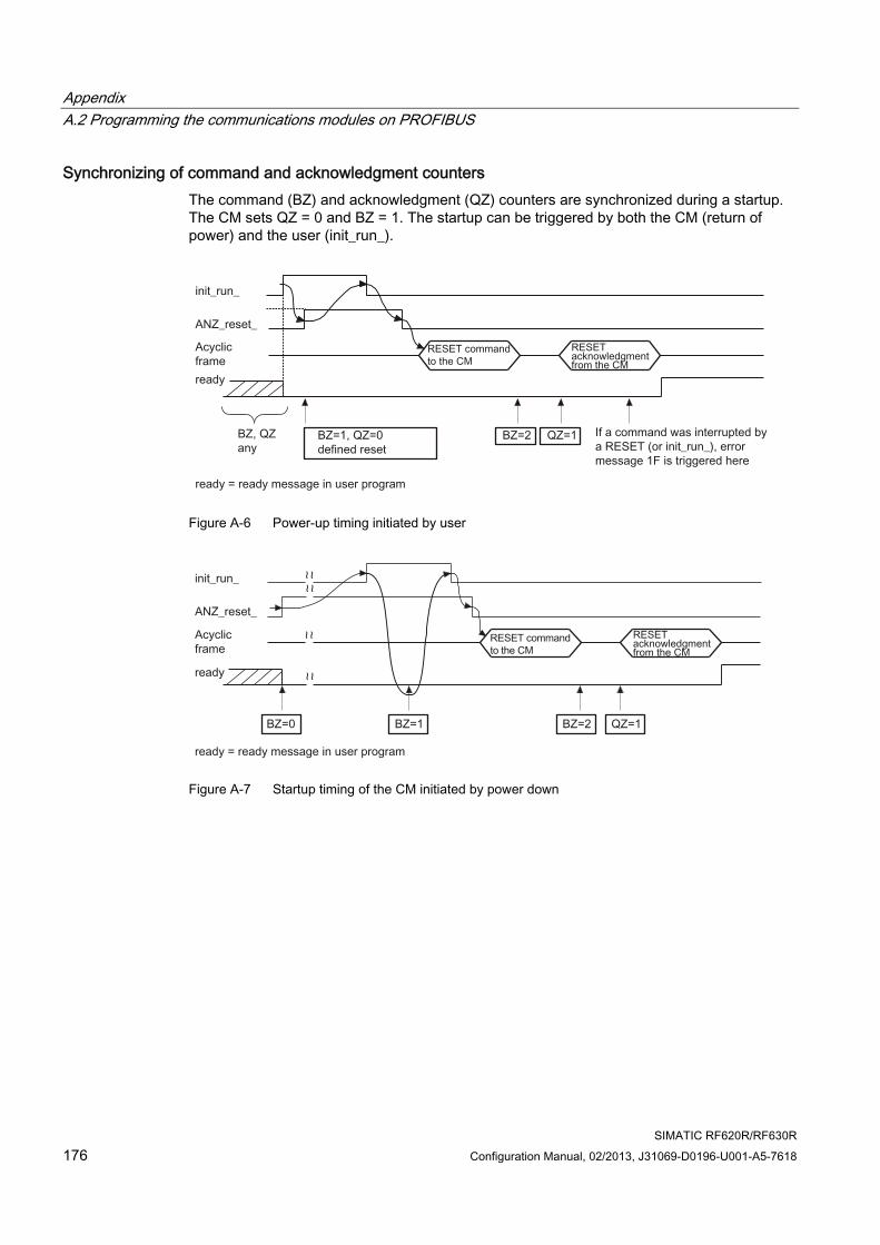
Appendix A.2 Programming the communications modules on PROFIBUS
SIMATIC RF620R/RF630R 176 Configuration Manual, 02/2013, J31069-D0196-U001-A5-7618
Synchronizing of command and acknowledgment counters The command (BZ) and acknowledgment (QZ) counters are synchronized during a startup. The CM sets QZ = 0 and BZ = 1. The startup can be triggered by both the CM (return of power) and the user (init_run_).
Figure A-6 Power-up timing initiated by user
Figure A-7 Startup timing of the CM initiated by power down
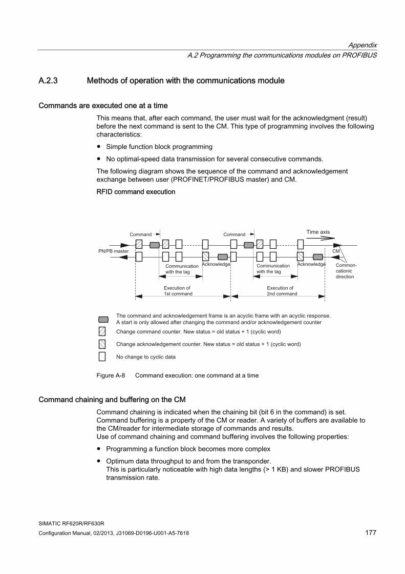
Appendix A.2 Programming the communications modules on PROFIBUS
SIMATIC RF620R/RF630R Configuration Manual, 02/2013, J31069-D0196-U001-A5-7618 177
A.2.3 Methods of operation with the communications module
Commands are executed one at a time This means that, after each command, the user must wait for the acknowledgment (result) before the next command is sent to the CM. This type of programming involves the following characteristics:
● Simple function block programming
● No optimal-speed data transmission for several consecutive commands.
The following diagram shows the sequence of the command and acknowledgement exchange between user (PROFINET/PROFIBUS master) and CM.
RFID command execution
Figure A-8 Command execution: one command at a time
Command chaining and buffering on the CM Command chaining is indicated when the chaining bit (bit 6 in the command) is set. Command buffering is a property of the CM or reader. A variety of buffers are available to the CM/reader for intermediate storage of commands and results. Use of command chaining and command buffering involves the following properties:
● Programming a function block becomes more complex
● Optimum data throughput to and from the transponder. This is particularly noticeable with high data lengths (> 1 KB) and slower PROFIBUS transmission rate.
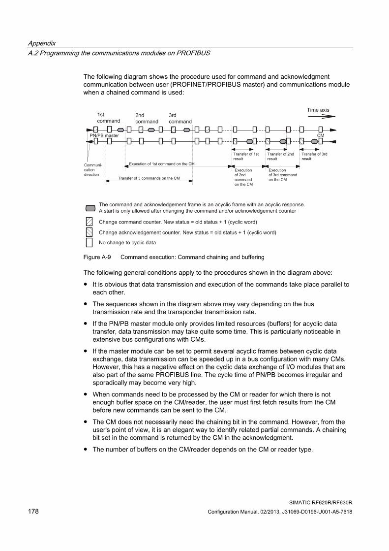
Appendix A.2 Programming the communications modules on PROFIBUS
SIMATIC RF620R/RF630R 178 Configuration Manual, 02/2013, J31069-D0196-U001-A5-7618
The following diagram shows the procedure used for command and acknowledgment communication between user (PROFINET/PROFIBUS master) and communications module when a chained command is used:
Figure A-9 Command execution: Command chaining and buffering
The following general conditions apply to the procedures shown in the diagram above:
● It is obvious that data transmission and execution of the commands take place parallel to each other.
● The sequences shown in the diagram above may vary depending on the bus transmission rate and the transponder transmission rate.
● If the PN/PB master module only provides limited resources (buffers) for acyclic data transfer, data transmission may take quite some time. This is particularly noticeable in extensive bus configurations with CMs.
● If the master module can be set to permit several acyclic frames between cyclic data exchange, data transmission can be speeded up in a bus configuration with many CMs. However, this has a negative effect on the cyclic data exchange of I/O modules that are also part of the same PROFIBUS line. The cycle time of PN/PB becomes irregular and sporadically may become very high.
● When commands need to be processed by the CM or reader for which there is not enough buffer space on the CM/reader, the user must first fetch results from the CM before new commands can be sent to the CM.
● The CM does not necessarily need the chaining bit in the command. However, from the user's point of view, it is an elegant way to identify related partial commands. A chaining bit set in the command is returned by the CM in the acknowledgment.
● The number of buffers on the CM/reader depends on the CM or reader type.
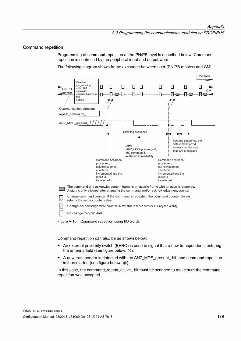
Appendix A.2 Programming the communications modules on PROFIBUS
SIMATIC RF620R/RF630R Configuration Manual, 02/2013, J31069-D0196-U001-A5-7618 179
Command repetition Programming of command repetition at the PN/PB level is described below. Command repetition is controlled by the peripheral input and output word.
The following diagram shows frame exchange between user (PN/PB master) and CM:
Figure A-10 Command repetition using I/O words
Command repetition can also be as shown below:
● An external proximity switch (BERO) is used to signal that a new transponder is entering the antenna field (see figure below: Ⓐ).
● A new transponder is detected with the ANZ_MDS_present_ bit, and command repetition is then started (see figure below: Ⓑ).
In this case, the command_repeat_active_ bit must be scanned to make sure the command repetition was accepted.
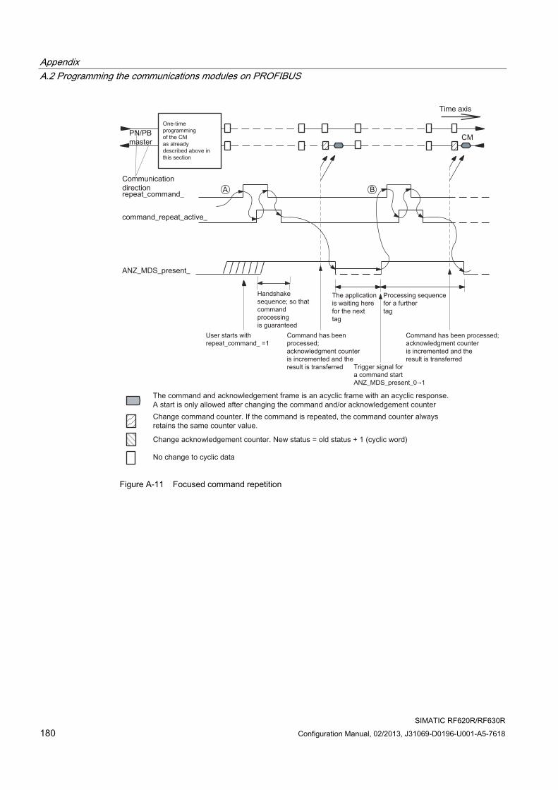
Appendix A.2 Programming the communications modules on PROFIBUS
SIMATIC RF620R/RF630R 180 Configuration Manual, 02/2013, J31069-D0196-U001-A5-7618
Figure A-11 Focused command repetition
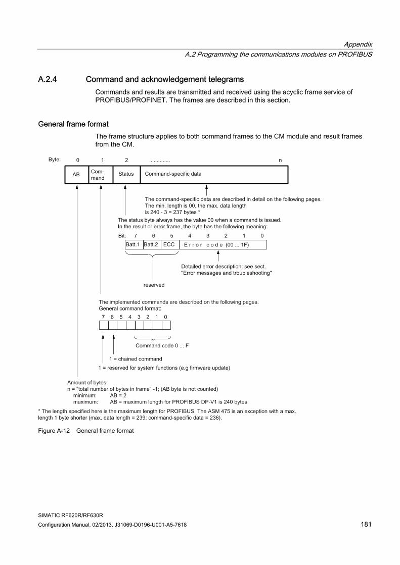
Appendix A.2 Programming the communications modules on PROFIBUS
SIMATIC RF620R/RF630R Configuration Manual, 02/2013, J31069-D0196-U001-A5-7618 181
A.2.4 Command and acknowledgement telegrams Commands and results are transmitted and received using the acyclic frame service of PROFIBUS/PROFINET. The frames are described in this section.
General frame format The frame structure applies to both command frames to the CM module and result frames from the CM.
Figure A-12 General frame format
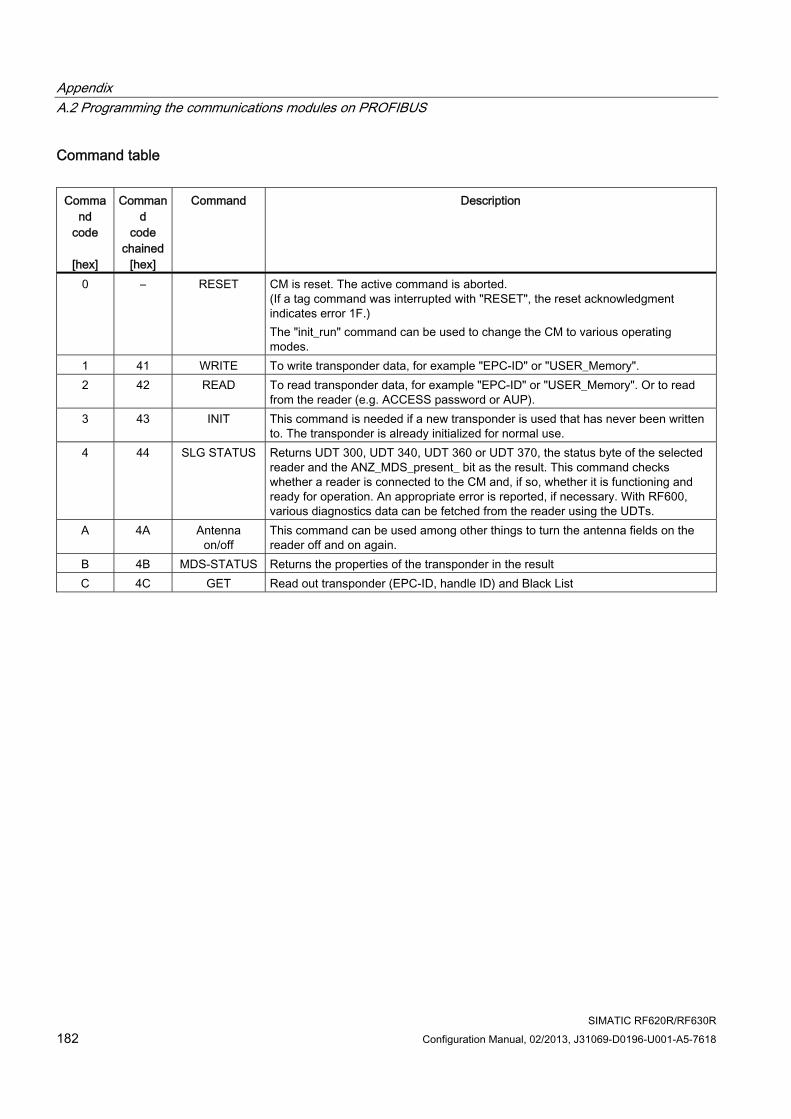
Appendix A.2 Programming the communications modules on PROFIBUS
SIMATIC RF620R/RF630R 182 Configuration Manual, 02/2013, J31069-D0196-U001-A5-7618
Command table
Command
code
[hex]
Command
code chained
[hex]
Command Description
0 – RESET CM is reset. The active command is aborted. (If a tag command was interrupted with "RESET", the reset acknowledgment indicates error 1F.) The "init_run" command can be used to change the CM to various operating modes.
1 41 WRITE To write transponder data, for example "EPC-ID" or "USER_Memory". 2 42 READ To read transponder data, for example "EPC-ID" or "USER_Memory". Or to read
from the reader (e.g. ACCESS password or AUP). 3 43 INIT This command is needed if a new transponder is used that has never been written
to. The transponder is already initialized for normal use. 4 44 SLG STATUS Returns UDT 300, UDT 340, UDT 360 or UDT 370, the status byte of the selected
reader and the ANZ_MDS_present_ bit as the result. This command checks whether a reader is connected to the CM and, if so, whether it is functioning and ready for operation. An appropriate error is reported, if necessary. With RF600, various diagnostics data can be fetched from the reader using the UDTs.
A 4A Antenna on/off
This command can be used among other things to turn the antenna fields on the reader off and on again.
B 4B MDS-STATUS Returns the properties of the transponder in the result C 4C GET Read out transponder (EPC-ID, handle ID) and Black List
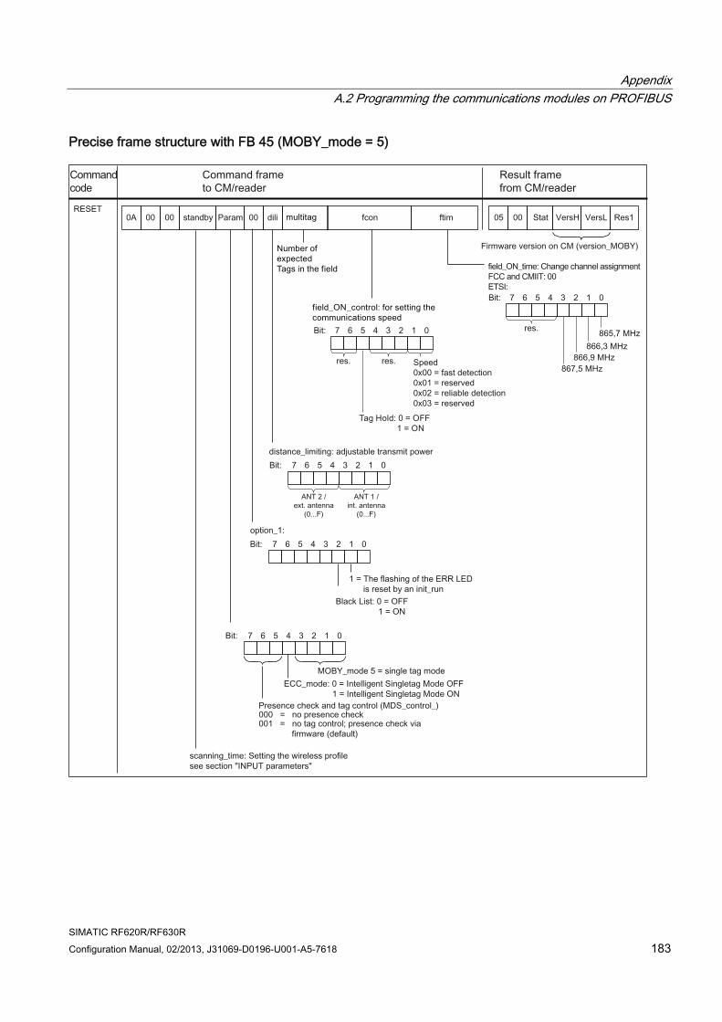
Appendix A.2 Programming the communications modules on PROFIBUS
SIMATIC RF620R/RF630R Configuration Manual, 02/2013, J31069-D0196-U001-A5-7618 183
Precise frame structure with FB 45 (MOBY_mode = 5)
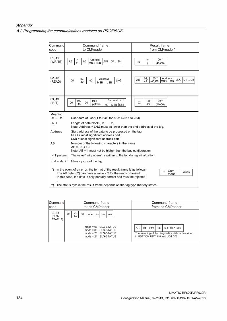
Appendix A.2 Programming the communications modules on PROFIBUS
SIMATIC RF620R/RF630R 184 Configuration Manual, 02/2013, J31069-D0196-U001-A5-7618
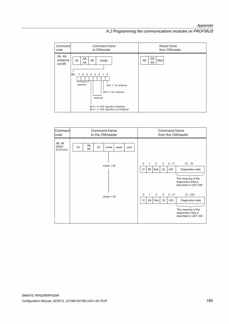
Appendix A.2 Programming the communications modules on PROFIBUS
SIMATIC RF620R/RF630R Configuration Manual, 02/2013, J31069-D0196-U001-A5-7618 185
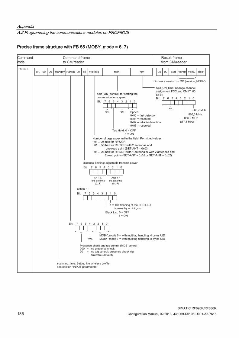
Appendix A.2 Programming the communications modules on PROFIBUS
SIMATIC RF620R/RF630R 186 Configuration Manual, 02/2013, J31069-D0196-U001-A5-7618
Precise frame structure with FB 55 (MOBY_mode = 6, 7)
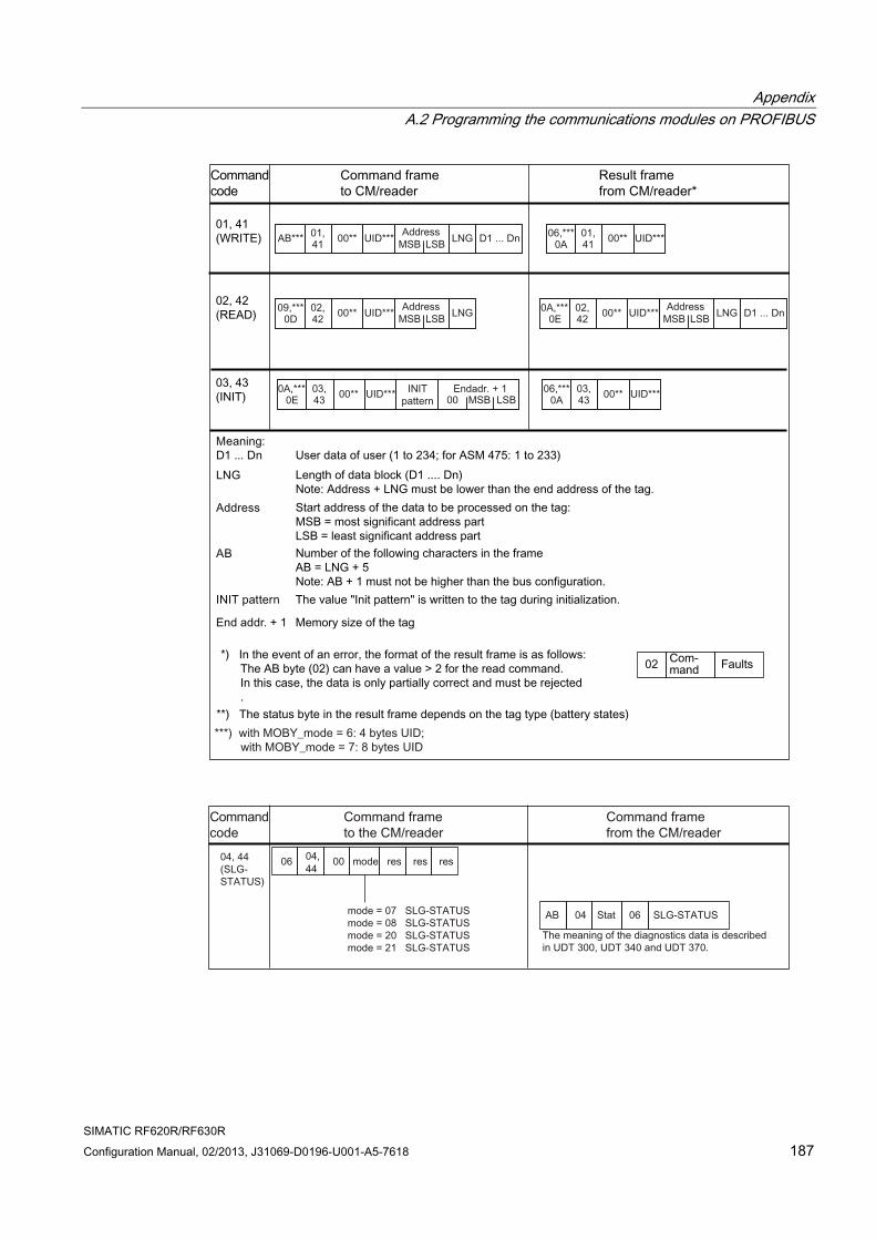
Appendix A.2 Programming the communications modules on PROFIBUS
SIMATIC RF620R/RF630R Configuration Manual, 02/2013, J31069-D0196-U001-A5-7618 187
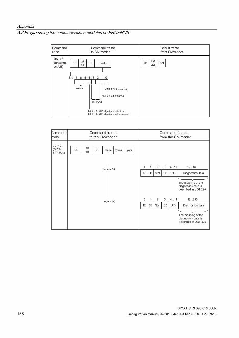
Appendix A.2 Programming the communications modules on PROFIBUS
SIMATIC RF620R/RF630R 188 Configuration Manual, 02/2013, J31069-D0196-U001-A5-7618
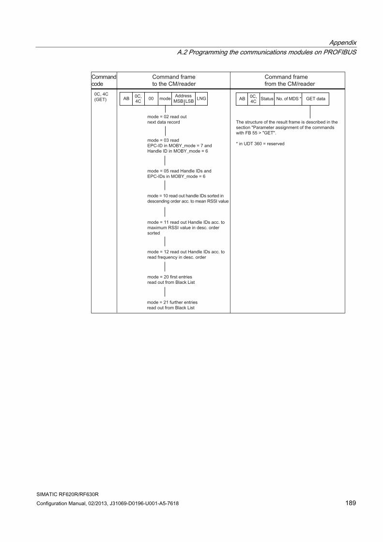
Appendix A.2 Programming the communications modules on PROFIBUS
SIMATIC RF620R/RF630R Configuration Manual, 02/2013, J31069-D0196-U001-A5-7618 189
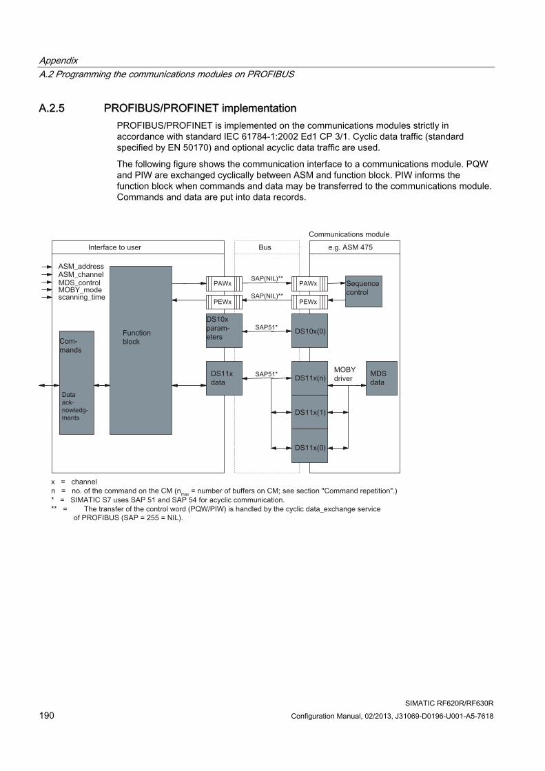
Appendix A.2 Programming the communications modules on PROFIBUS
SIMATIC RF620R/RF630R 190 Configuration Manual, 02/2013, J31069-D0196-U001-A5-7618
A.2.5 PROFIBUS/PROFINET implementation PROFIBUS/PROFINET is implemented on the communications modules strictly in accordance with standard IEC 61784-1:2002 Ed1 CP 3/1. Cyclic data traffic (standard specified by EN 50170) and optional acyclic data traffic are used.
The following figure shows the communication interface to a communications module. PQW and PIW are exchanged cyclically between ASM and function block. PIW informs the function block when commands and data may be transferred to the communications module. Commands and data are put into data records.
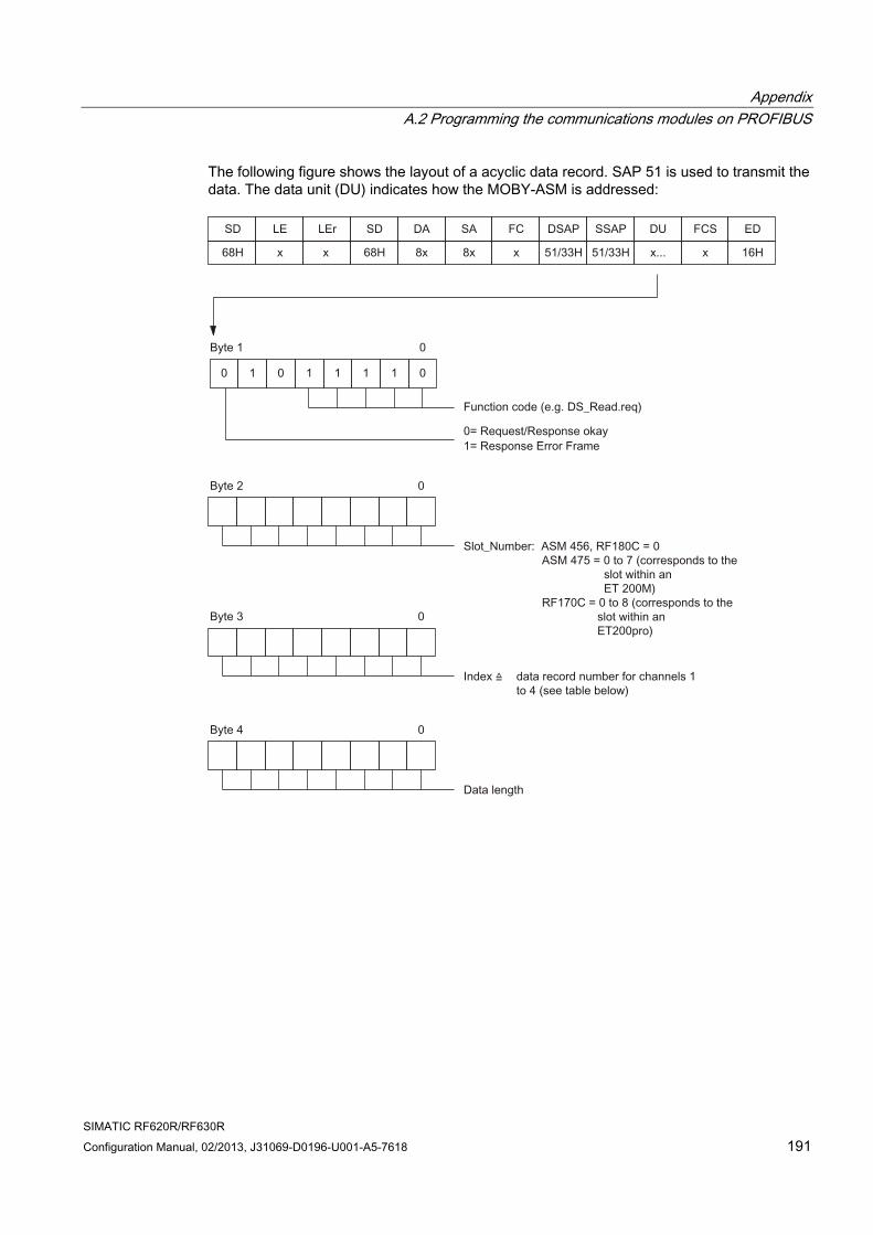
Appendix A.2 Programming the communications modules on PROFIBUS
SIMATIC RF620R/RF630R Configuration Manual, 02/2013, J31069-D0196-U001-A5-7618 191
The following figure shows the layout of a acyclic data record. SAP 51 is used to transmit the data. The data unit (DU) indicates how the MOBY-ASM is addressed:
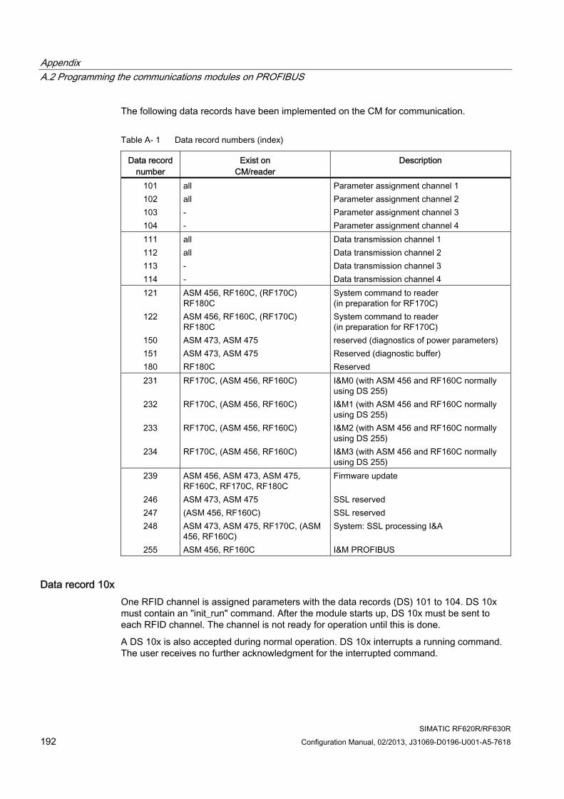
Appendix A.2 Programming the communications modules on PROFIBUS
SIMATIC RF620R/RF630R 192 Configuration Manual, 02/2013, J31069-D0196-U001-A5-7618
The following data records have been implemented on the CM for communication.
Table A- 1 Data record numbers (index)
Data recordnumber
Exist on CM/reader
Description
101 102 103 104
all all - -
Parameter assignment channel 1 Parameter assignment channel 2 Parameter assignment channel 3 Parameter assignment channel 4
111 112 113 114
all all - -
Data transmission channel 1 Data transmission channel 2 Data transmission channel 3 Data transmission channel 4
121
122
150 151 180
ASM 456, RF160C, (RF170C) RF180C ASM 456, RF160C, (RF170C) RF180C ASM 473, ASM 475 ASM 473, ASM 475 RF180C
System command to reader (in preparation for RF170C) System command to reader (in preparation for RF170C) reserved (diagnostics of power parameters) Reserved (diagnostic buffer) Reserved
231
232
233
234
RF170C, (ASM 456, RF160C) RF170C, (ASM 456, RF160C) RF170C, (ASM 456, RF160C) RF170C, (ASM 456, RF160C)
I&M0 (with ASM 456 and RF160C normally using DS 255) I&M1 (with ASM 456 and RF160C normally using DS 255) I&M2 (with ASM 456 and RF160C normally using DS 255) I&M3 (with ASM 456 and RF160C normally using DS 255)
239
246 247 248
255
ASM 456, ASM 473, ASM 475, RF160C, RF170C, RF180C ASM 473, ASM 475 (ASM 456, RF160C) ASM 473, ASM 475, RF170C, (ASM 456, RF160C) ASM 456, RF160C
Firmware update SSL reserved SSL reserved System: SSL processing I&A I&M PROFIBUS
Data record 10x One RFID channel is assigned parameters with the data records (DS) 101 to 104. DS 10x must contain an "init_run" command. After the module starts up, DS 10x must be sent to each RFID channel. The channel is not ready for operation until this is done.
A DS 10x is also accepted during normal operation. DS 10x interrupts a running command. The user receives no further acknowledgment for the interrupted command.
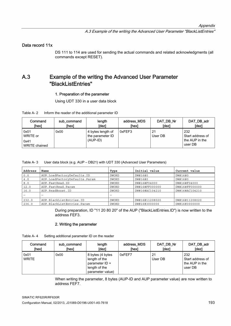
Appendix A.3 Example of the writing the Advanced User Parameter "BlackListEntries"
SIMATIC RF620R/RF630R Configuration Manual, 02/2013, J31069-D0196-U001-A5-7618 193
Data record 11x DS 111 to 114 are used for sending the actual commands and related acknowledgments (all commands except RESET).
A.3 Example of the writing the Advanced User Parameter "BlackListEntries"
1. Preparation of the parameter
Using UDT 330 in a user data block
Table A- 2 Inform the reader of the additional parameter ID
Command [hex]
sub_command [hex]
length [dez]
address_MDS [hex]
DAT_DB_Nr [dez]
DAT_DB_adr [dez]
0x01 WRITE or 0x41 WRITE chained
0x00 4 bytes length of the parameter ID (AUP-ID)
0xFEF3 21 User DB
232 Start address of the AUP in the user DB
Table A- 3 User data block (e.g. AUP – DB21) with UDT 330 (Advanced User Parameters)
Address Name Type Initial value Current value 0.0 AUP.LoadFactoryDefaults.ID DWORD DW#16#0 DW#16#0 4.0 AUP.LoadFactoryDefaults.Param DWORD DW#16#0 DW#16#0 8.0 AUP.FastRead.ID DWORD DW#16#F04000 DW#16#F04000 12.0 AUP.FastRead.Param DWORD DW#16#FF000000 DW#16#FF000000 16.0 AUP.ReadBoost.ID DWORD DW#16#AC104210 DW#16#AC104210 … … … 232.0 AUP.BlackListEntries.ID DWORD DW#16#11208020 DW#16#11208020 236.0 AUP.BlackListEntries.Param DWORD DW#16#3000000 DW#16#3000000
During preparation, ID "11 20 80 20" of the AUP ("BlackListEntries.ID") is now written to the address FEF3.
2. Writing the parameter
Table A- 4 Setting additional parameter ID on the reader
Command [hex]
sub_command [hex]
length [dez]
address_MDS [hex]
DAT_DB_Nr [dez]
DAT_DB_adr [dez]
0x01 WRITE
0x00 8 bytes (4 bytes length of the parameter ID + length of the parameter value)
0xFEF7 21 User DB
232 Start address of the AUP in the user DB
When writing the parameter, 8 bytes (AUP-ID and AUP parameter value) are now written to address FEF7.
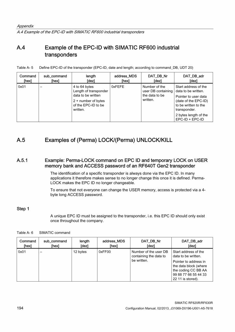
Appendix A.4 Example of the EPC-ID with SIMATIC RF600 industrial transponders
SIMATIC RF620R/RF630R 194 Configuration Manual, 02/2013, J31069-D0196-U001-A5-7618
A.4 Example of the EPC-ID with SIMATIC RF600 industrial transponders
Table A- 5 Define EPC-ID of the transponder (EPC-ID, date and length; according to command_DB, UDT 20)
Command [hex]
sub_command [hex]
length [dez]
address_MDS [hex]
DAT_DB_Nr [dez]
DAT_DB_adr [dez]
0x01 – 4 to 64 bytes Length of transponder data to be written 2 + number of bytes of the EPC-ID to be written.
0xFEFE Number of the user DB containing the data to be written.
Start address of the data to be written. Pointer to user data (date of the EPC-ID) to be written to the transponder. 2 bytes length of the EPC-ID + EPC-ID
A.5 Examples of (Perma) LOCK/(Perma) UNLOCK/KILL
A.5.1 Example: Perma-LOCK command on EPC ID and temporary LOCK on USER memory bank and ACCESS password of an RF640T Gen2 transponder
The identification of a specific transponder is always done via the EPC ID. In many applications it therefore makes sense to no longer change this once it is defined. Perma-LOCK makes the EPC ID no longer changeable.
To ensure that not everyone can change the USER memory, access is protected via a 4-byte long ACCESS password.
Step 1 A unique EPC ID must be assigned to the transponder, i.e. this EPC ID should only exist once throughout the company.
Table A- 6 SIMATIC command
Command [hex]
sub_command [hex]
length [dez]
address_MDS [hex]
DAT_DB_Nr [dez]
DAT_DB_adr [dez]
0x01 – 12 bytes 0xFF00 Number of the user DB containing the data to be written.
Start address of the data to be written. Pointer to address in the data block (where the coding CC BB AA 99 88 77 66 55 44 33 22 11 is stored).
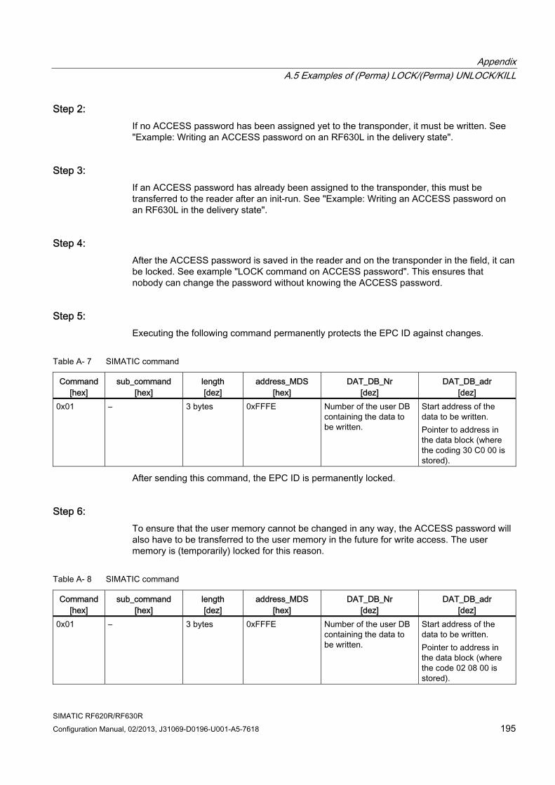
Appendix A.5 Examples of (Perma) LOCK/(Perma) UNLOCK/KILL
SIMATIC RF620R/RF630R Configuration Manual, 02/2013, J31069-D0196-U001-A5-7618 195
Step 2: If no ACCESS password has been assigned yet to the transponder, it must be written. See "Example: Writing an ACCESS password on an RF630L in the delivery state".
Step 3: If an ACCESS password has already been assigned to the transponder, this must be transferred to the reader after an init-run. See "Example: Writing an ACCESS password on an RF630L in the delivery state".
Step 4: After the ACCESS password is saved in the reader and on the transponder in the field, it can be locked. See example "LOCK command on ACCESS password". This ensures that nobody can change the password without knowing the ACCESS password.
Step 5: Executing the following command permanently protects the EPC ID against changes.
Table A- 7 SIMATIC command
Command [hex]
sub_command [hex]
length [dez]
address_MDS [hex]
DAT_DB_Nr [dez]
DAT_DB_adr [dez]
0x01 – 3 bytes 0xFFFE Number of the user DB containing the data to be written.
Start address of the data to be written. Pointer to address in the data block (where the coding 30 C0 00 is stored).
After sending this command, the EPC ID is permanently locked.
Step 6: To ensure that the user memory cannot be changed in any way, the ACCESS password will also have to be transferred to the user memory in the future for write access. The user memory is (temporarily) locked for this reason.
Table A- 8 SIMATIC command
Command [hex]
sub_command [hex]
length [dez]
address_MDS [hex]
DAT_DB_Nr [dez]
DAT_DB_adr [dez]
0x01 – 3 bytes 0xFFFE Number of the user DB containing the data to be written.
Start address of the data to be written. Pointer to address in the data block (where the code 02 08 00 is stored).
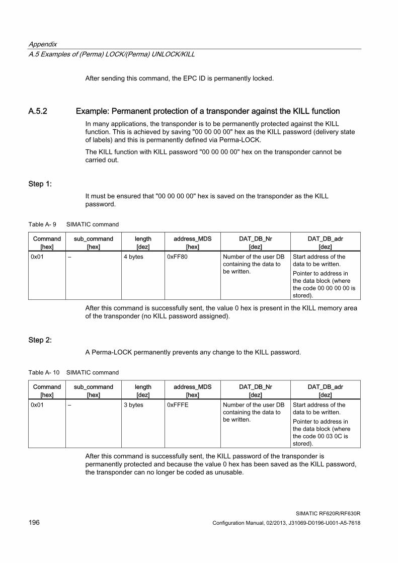
Appendix A.5 Examples of (Perma) LOCK/(Perma) UNLOCK/KILL
SIMATIC RF620R/RF630R 196 Configuration Manual, 02/2013, J31069-D0196-U001-A5-7618
After sending this command, the EPC ID is permanently locked.
A.5.2 Example: Permanent protection of a transponder against the KILL function In many applications, the transponder is to be permanently protected against the KILL function. This is achieved by saving "00 00 00 00" hex as the KILL password (delivery state of labels) and this is permanently defined via Perma-LOCK.
The KILL function with KILL password "00 00 00 00" hex on the transponder cannot be carried out.
Step 1: It must be ensured that "00 00 00 00" hex is saved on the transponder as the KILL password.
Table A- 9 SIMATIC command
Command [hex]
sub_command [hex]
length [dez]
address_MDS [hex]
DAT_DB_Nr [dez]
DAT_DB_adr [dez]
0x01 – 4 bytes 0xFF80 Number of the user DB containing the data to be written.
Start address of the data to be written. Pointer to address in the data block (where the code 00 00 00 00 is stored).
After this command is successfully sent, the value 0 hex is present in the KILL memory area of the transponder (no KILL password assigned).
Step 2: A Perma-LOCK permanently prevents any change to the KILL password.
Table A- 10 SIMATIC command
Command [hex]
sub_command [hex]
length [dez]
address_MDS [hex]
DAT_DB_Nr [dez]
DAT_DB_adr [dez]
0x01 – 3 bytes 0xFFFE Number of the user DB containing the data to be written.
Start address of the data to be written. Pointer to address in the data block (where the code 00 03 0C is stored).
After this command is successfully sent, the KILL password of the transponder is permanently protected and because the value 0 hex has been saved as the KILL password, the transponder can no longer be coded as unusable.
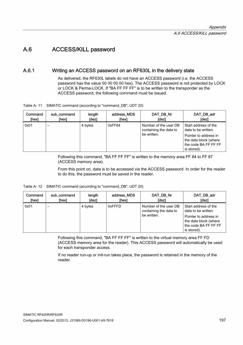
Appendix A.6 ACCESS/KILL password
SIMATIC RF620R/RF630R Configuration Manual, 02/2013, J31069-D0196-U001-A5-7618 197
A.6 ACCESS/KILL password
A.6.1 Writing an ACCESS password on an RF630L in the delivery state As delivered, the RF630L labels do not have an ACCESS password (i.e. the ACCESS password has the value 00 00 00 00 hex). The ACCESS password is not protected by LOCK or LOCK & Perma-LOCK. If "BA FF FF FF" is to be written to the transponder as the ACCESS password, the following command must be issued.
Table A- 11 SIMATIC command (according to "command_DB", UDT 20)
Command [hex]
sub_command [hex]
length [dez]
address_MDS [hex]
DAT_DB_Nr [dez]
DAT_DB_adr [dez]
0x01 – 4 bytes 0xFF84 Number of the user DB containing the data to be written.
Start address of the data to be written. Pointer to address in the data block (where the code BA FF FF FF is stored).
Following this command, "BA FF FF FF" is written to the memory area FF 84 to FF 87 (ACCESS memory area).
From this point on, data is to be accessed via the ACCESS password. In order for the reader to do this, the password must be saved in the reader.
Table A- 12 SIMATIC command (according to "command_DB", UDT 20)
Command [hex]
sub_command [hex]
length [dez]
address_MDS [hex]
DAT_DB_Nr [dez]
DAT_DB_adr [dez]
0x01 – 4 bytes 0xFFFD Number of the user DB containing the data to be written.
Start address of the data to be written. Pointer to address in the data block (where the code BA FF FF FF is stored).
Following this command, "BA FF FF FF" is written to the virtual memory area FF FD (ACCESS memory area for the reader). This ACCESS password will automatically be used for each transponder access.
If no reader run-up or init-run takes place, the password is retained in the memory of the reader.
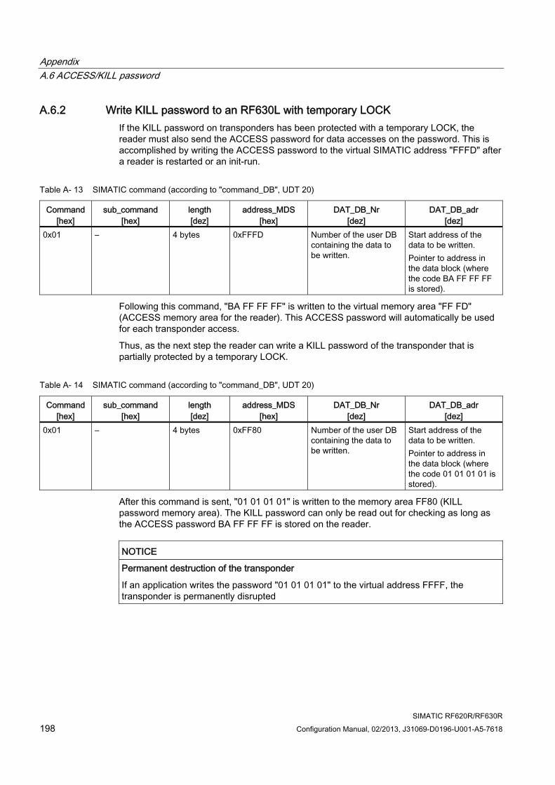
Appendix A.6 ACCESS/KILL password
SIMATIC RF620R/RF630R 198 Configuration Manual, 02/2013, J31069-D0196-U001-A5-7618
A.6.2 Write KILL password to an RF630L with temporary LOCK If the KILL password on transponders has been protected with a temporary LOCK, the reader must also send the ACCESS password for data accesses on the password. This is accomplished by writing the ACCESS password to the virtual SIMATIC address "FFFD" after a reader is restarted or an init-run.
Table A- 13 SIMATIC command (according to "command_DB", UDT 20)
Command [hex]
sub_command [hex]
length [dez]
address_MDS [hex]
DAT_DB_Nr [dez]
DAT_DB_adr [dez]
0x01 – 4 bytes 0xFFFD Number of the user DB containing the data to be written.
Start address of the data to be written. Pointer to address in the data block (where the code BA FF FF FF is stored).
Following this command, "BA FF FF FF" is written to the virtual memory area "FF FD" (ACCESS memory area for the reader). This ACCESS password will automatically be used for each transponder access.
Thus, as the next step the reader can write a KILL password of the transponder that is partially protected by a temporary LOCK.
Table A- 14 SIMATIC command (according to "command_DB", UDT 20)
Command [hex]
sub_command [hex]
length [dez]
address_MDS [hex]
DAT_DB_Nr [dez]
DAT_DB_adr [dez]
0x01 – 4 bytes 0xFF80 Number of the user DB containing the data to be written.
Start address of the data to be written. Pointer to address in the data block (where the code 01 01 01 01 is stored).
After this command is sent, "01 01 01 01" is written to the memory area FF80 (KILL password memory area). The KILL password can only be read out for checking as long as the ACCESS password BA FF FF FF is stored on the reader.
NOTICE Permanent destruction of the transponder
If an application writes the password "01 01 01 01" to the virtual address FFFF, the transponder is permanently disrupted
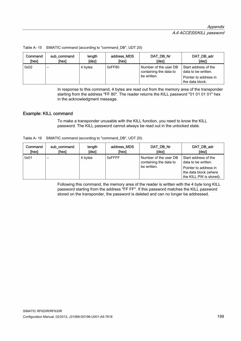
Appendix A.6 ACCESS/KILL password
SIMATIC RF620R/RF630R Configuration Manual, 02/2013, J31069-D0196-U001-A5-7618 199
Table A- 15 SIMATIC command (according to "command_DB", UDT 20)
Command [hex]
sub_command [hex]
length [dez]
address_MDS [hex]
DAT_DB_Nr [dez]
DAT_DB_adr [dez]
0x02 – 4 bytes 0xFF80 Number of the user DB containing the data to be written.
Start address of the data to be written. Pointer to address in the data block.
In response to this command, 4 bytes are read out from the memory area of the transponder starting from the address "FF 80". The reader returns the KILL password "01 01 01 01" hex in the acknowledgment message.
Example: KILL command To make a transponder unusable with the KILL function, you need to know the KILL password. The KILL password cannot always be read out in the unlocked state.
Table A- 16 SIMATIC command (according to "command_DB", UDT 20)
Command [hex]
sub_command [hex]
length [dez]
address_MDS [hex]
DAT_DB_Nr [dez]
DAT_DB_adr [dez]
0x01 – 4 bytes 0xFFFF Number of the user DB containing the data to be written.
Start address of the data to be written. Pointer to address in the data block (where the KILL PW is stored).
Following this command, the memory area of the reader is written with the 4 byte long KILL password starting from the address "FF FF". If this password matches the KILL password stored on the transponder, the password is deleted and can no longer be addressed.
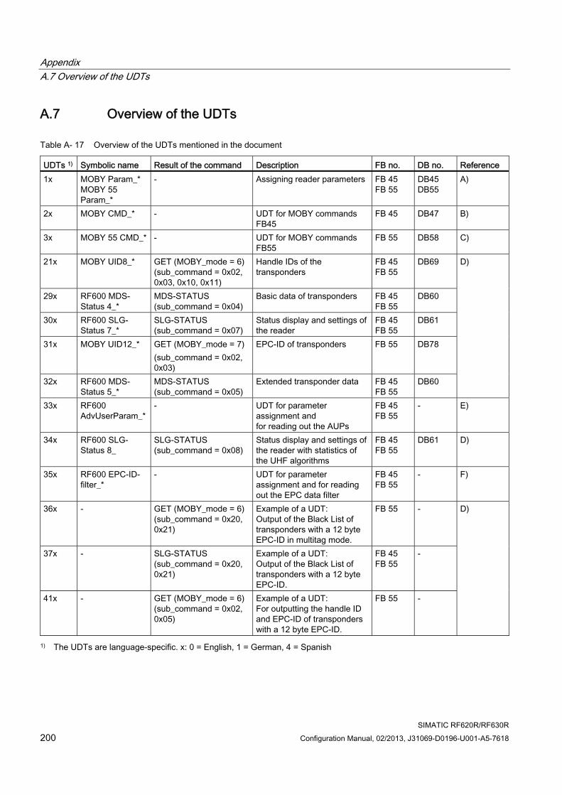
Appendix A.7 Overview of the UDTs
SIMATIC RF620R/RF630R 200 Configuration Manual, 02/2013, J31069-D0196-U001-A5-7618
A.7 Overview of the UDTs
Table A- 17 Overview of the UDTs mentioned in the document
UDTs 1) Symbolic name Result of the command Description FB no. DB no. Reference 1x MOBY Param_*
MOBY 55 Param_*
- Assigning reader parameters FB 45 FB 55
DB45 DB55
A)
2x MOBY CMD_* - UDT for MOBY commands FB45
FB 45 DB47 B)
3x MOBY 55 CMD_* - UDT for MOBY commands FB55
FB 55 DB58 C)
21x MOBY UID8_* GET (MOBY_mode = 6)(sub_command = 0x02, 0x03, 0x10, 0x11)
Handle IDs of the transponders
FB 45 FB 55
DB69
29x RF600 MDS-Status 4_*
MDS-STATUS (sub_command = 0x04)
Basic data of transponders FB 45 FB 55
DB60
30x RF600 SLG-Status 7_*
SLG-STATUS (sub_command = 0x07)
Status display and settings of the reader
FB 45 FB 55
DB61
31x MOBY UID12_* GET (MOBY_mode = 7) (sub_command = 0x02, 0x03)
EPC-ID of transponders FB 55 DB78
32x RF600 MDS-Status 5_*
MDS-STATUS (sub_command = 0x05)
Extended transponder data FB 45 FB 55
DB60
D)
33x RF600 AdvUserParam_*
- UDT for parameter assignment and for reading out the AUPs
FB 45 FB 55
- E)
34x RF600 SLG-Status 8_
SLG-STATUS (sub_command = 0x08)
Status display and settings of the reader with statistics of the UHF algorithms
FB 45 FB 55
DB61 D)
35x RF600 EPC-ID-filter_*
- UDT for parameter assignment and for reading out the EPC data filter
FB 45 FB 55
- F)
36x - GET (MOBY_mode = 6)(sub_command = 0x20, 0x21)
Example of a UDT: Output of the Black List of transponders with a 12 byte EPC-ID in multitag mode.
FB 55 -
37x - SLG-STATUS (sub_command = 0x20, 0x21)
Example of a UDT: Output of the Black List of transponders with a 12 byte EPC-ID.
FB 45 FB 55
-
41x - GET (MOBY_mode = 6)(sub_command = 0x02, 0x05)
Example of a UDT: For outputting the handle ID and EPC-ID of transponders with a 12 byte EPC-ID.
FB 55 -
D)
1) The UDTs are language-specific. x: 0 = English, 1 = German, 4 = Spanish
Appendix A.7 Overview of the UDTs
SIMATIC RF620R/RF630R Configuration Manual, 02/2013, J31069-D0196-U001-A5-7618 201
References to the UDTs:
● A) Parameter assignment in the parameter DB (Page 25) and Parameter assignment in the parameter DB (Page 49)
● B) RFID commands of FB 45 (Page 34)
● C) UDT 30 - the structure for the RFID command (Page 58)
● D) UDTs of FB 45 (Page 41) and UDTs of FB 55 (Page 71)
● E) UDT for Advanced User Parameters (Page 148)
● F) UDT for EPC Data Filter (Page 153)

Appendix A.7 Overview of the UDTs
SIMATIC RF620R/RF630R 202 Configuration Manual, 02/2013, J31069-D0196-U001-A5-7618
SIMATIC RF620R/RF630R Configuration Manual, 02/2013, J31069-D0196-U001-A5-7618 203
Firmware update BB.1 Requirements for the firmware update
The firmware (FW) can be downloaded to a reader via the CM. For this purpose, you need a PC/programming device with SIMATIC STEP 7 as of V5.1 with SP3.
Note FW update via the TIA Portal
You can also update the firmware of the RF600 reader in the TIA Portal via the communication modules.
You will find additional information on operating the RF600 reader on the RFID system DVD "Software & Documentation (http://support.automation.siemens.com/WW/view/en/4090419)" (order no.: 6GT2080-2AA20).
In order to be able to perform the FW update, you require the update file suitable for your CM. You can download these files from the "Industry Online Support" Web page.
FW update files: (http://support.automation.siemens.com/WW/view/en/61199127)
There are different update files for the three different communication modules RF160C, RF180C and ASM 456.
You can perform the firmware update for up to two readers at the same time. The download depends on the configuration:
● If only one reader is connected to the CM, the download only takes place for this reader.
● If two readers are connected to the CM, the new firmware is downloaded to both readers.
Only one or two readers of the RF600 series are permitted to be connected to the CM. A FW update is only possible for readers as of FW version 2.0.
Firmware update B.2 Performing the firmware update
SIMATIC RF620R/RF630R 204 Configuration Manual, 02/2013, J31069-D0196-U001-A5-7618
B.2 Performing the firmware update This manual describes the FW update for the communication modules RF160C, RF180C and ASM 456. As the firmware update procedure is identical for the communication modules RF160C and ASM 456, the firmware update is illustrated on the basis of RF160C in the following chapter.
The update procedure for the communication module RF180C differs slightly, so the FW update for RF180C is illustrated separately.
Preparation for the FW update 1. Download the update file suitable for your CM.
You will find the update file on the "Industry Online Support" Web page:
– FW update files: (http://support.automation.siemens.com/WW/view/en/61199127)
2. Save the file on your PC or programming device.
3. Unzip the file.
The file contains 3 "*.upd" files.
B.3 Firmware update with RF160C and ASM 456
Step 1: Start the update 1. Start the SIMATIC Manager.
2. Start "HW Config" with a double-click on the hardware of the current project.
3. Select the CM on which the readers are operated.
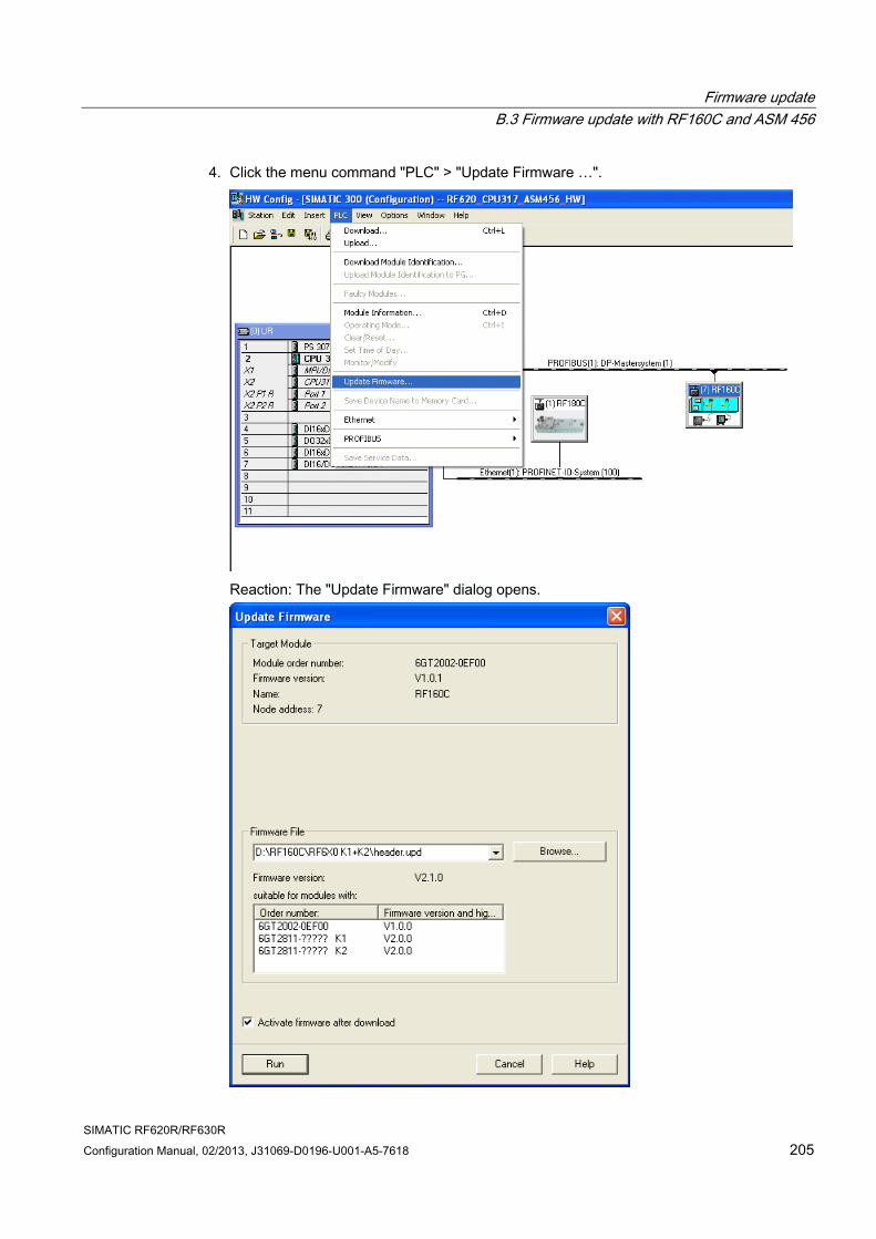
Firmware update B.3 Firmware update with RF160C and ASM 456
SIMATIC RF620R/RF630R Configuration Manual, 02/2013, J31069-D0196-U001-A5-7618 205
4. Click the menu command "PLC" > "Update Firmware …".
Reaction: The "Update Firmware" dialog opens.
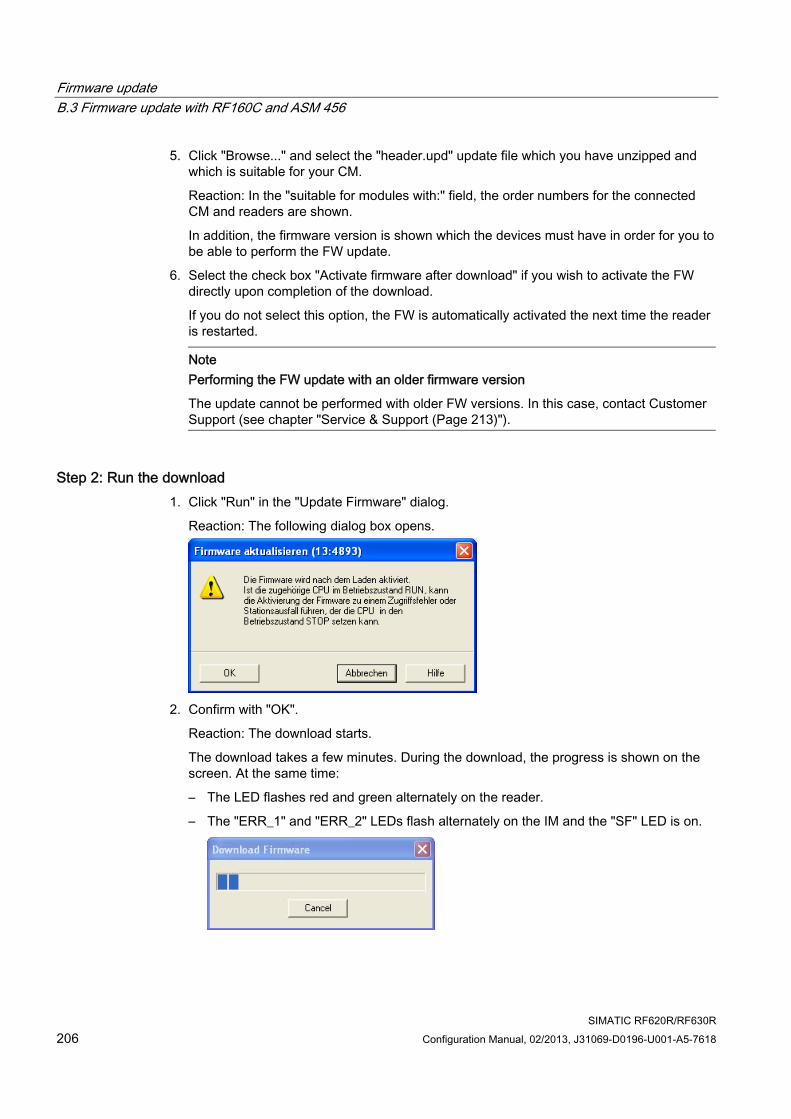
Firmware update B.3 Firmware update with RF160C and ASM 456
SIMATIC RF620R/RF630R 206 Configuration Manual, 02/2013, J31069-D0196-U001-A5-7618
5. Click "Browse..." and select the "header.upd" update file which you have unzipped and which is suitable for your CM.
Reaction: In the "suitable for modules with:" field, the order numbers for the connected CM and readers are shown.
In addition, the firmware version is shown which the devices must have in order for you to be able to perform the FW update.
6. Select the check box "Activate firmware after download" if you wish to activate the FW directly upon completion of the download.
If you do not select this option, the FW is automatically activated the next time the reader is restarted.
Note Performing the FW update with an older firmware version
The update cannot be performed with older FW versions. In this case, contact Customer Support (see chapter "Service & Support (Page 213)").
Step 2: Run the download 1. Click "Run" in the "Update Firmware" dialog.
Reaction: The following dialog box opens.
2. Confirm with "OK".
Reaction: The download starts.
The download takes a few minutes. During the download, the progress is shown on the screen. At the same time:
– The LED flashes red and green alternately on the reader.
– The "ERR_1" and "ERR_2" LEDs flash alternately on the IM and the "SF" LED is on.
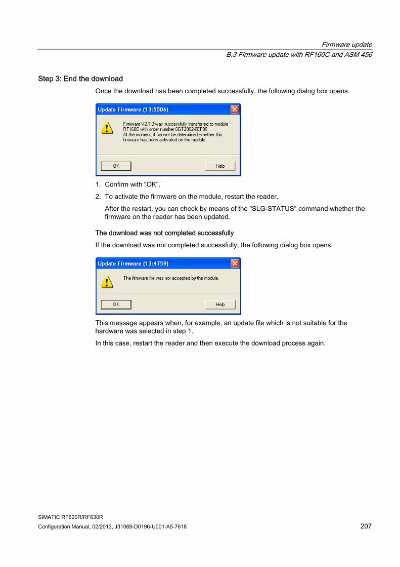
Firmware update B.3 Firmware update with RF160C and ASM 456
SIMATIC RF620R/RF630R Configuration Manual, 02/2013, J31069-D0196-U001-A5-7618 207
Step 3: End the download Once the download has been completed successfully, the following dialog box opens.
1. Confirm with "OK".
2. To activate the firmware on the module, restart the reader.
After the restart, you can check by means of the "SLG-STATUS" command whether the firmware on the reader has been updated.
The download was not completed successfully
If the download was not completed successfully, the following dialog box opens.
This message appears when, for example, an update file which is not suitable for the hardware was selected in step 1.
In this case, restart the reader and then execute the download process again.
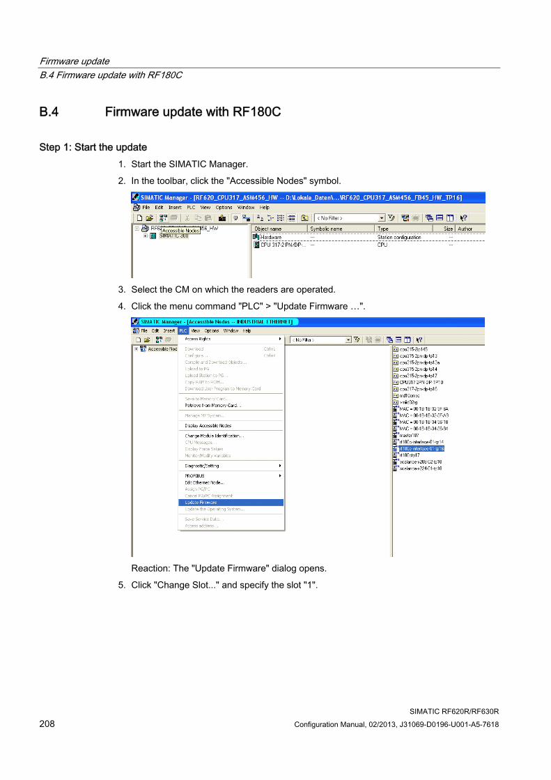
Firmware update B.4 Firmware update with RF180C
SIMATIC RF620R/RF630R 208 Configuration Manual, 02/2013, J31069-D0196-U001-A5-7618
B.4 Firmware update with RF180C
Step 1: Start the update 1. Start the SIMATIC Manager.
2. In the toolbar, click the "Accessible Nodes" symbol.
3. Select the CM on which the readers are operated.
4. Click the menu command "PLC" > "Update Firmware …".
Reaction: The "Update Firmware" dialog opens.
5. Click "Change Slot..." and specify the slot "1".
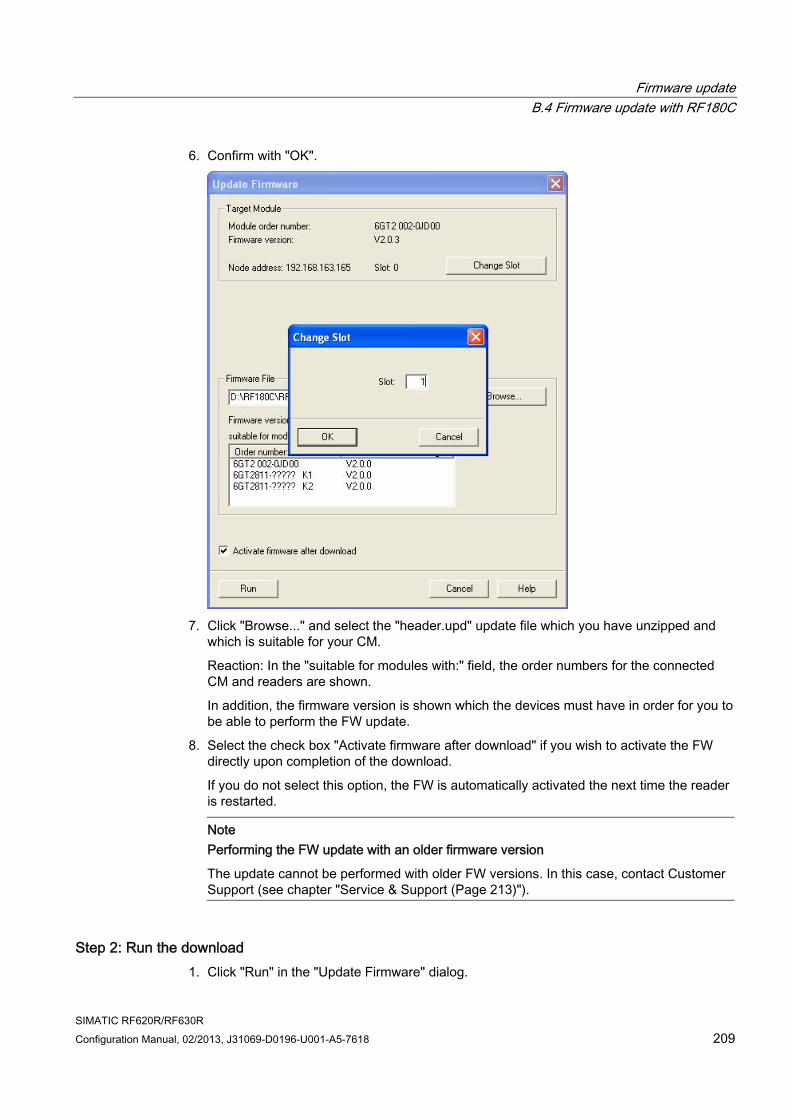
Firmware update B.4 Firmware update with RF180C
SIMATIC RF620R/RF630R Configuration Manual, 02/2013, J31069-D0196-U001-A5-7618 209
6. Confirm with "OK".
7. Click "Browse..." and select the "header.upd" update file which you have unzipped and
which is suitable for your CM.
Reaction: In the "suitable for modules with:" field, the order numbers for the connected CM and readers are shown.
In addition, the firmware version is shown which the devices must have in order for you to be able to perform the FW update.
8. Select the check box "Activate firmware after download" if you wish to activate the FW directly upon completion of the download.
If you do not select this option, the FW is automatically activated the next time the reader is restarted.
Note Performing the FW update with an older firmware version
The update cannot be performed with older FW versions. In this case, contact Customer Support (see chapter "Service & Support (Page 213)").
Step 2: Run the download 1. Click "Run" in the "Update Firmware" dialog.
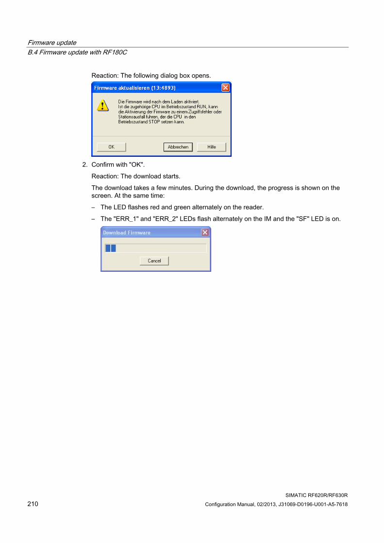
Firmware update B.4 Firmware update with RF180C
SIMATIC RF620R/RF630R 210 Configuration Manual, 02/2013, J31069-D0196-U001-A5-7618
Reaction: The following dialog box opens.
2. Confirm with "OK".
Reaction: The download starts.
The download takes a few minutes. During the download, the progress is shown on the screen. At the same time:
– The LED flashes red and green alternately on the reader.
– The "ERR_1" and "ERR_2" LEDs flash alternately on the IM and the "SF" LED is on.

Firmware update B.4 Firmware update with RF180C
SIMATIC RF620R/RF630R Configuration Manual, 02/2013, J31069-D0196-U001-A5-7618 211
Step 3: End the download Once the download has been completed successfully, the following dialog box opens.
1. Confirm with "OK".
2. To activate the firmware on the module, restart the reader.
After the restart, you can check by means of the "SLG-STATUS" command whether the firmware on the reader has been updated.
The download was not completed successfully
If the download was not completed successfully, the following dialog box opens.
This message appears when, for example, an update file which is not suitable for the hardware was selected in step 1.
In this case, restart the reader and then execute the download process again.

Firmware update B.4 Firmware update with RF180C
SIMATIC RF620R/RF630R 212 Configuration Manual, 02/2013, J31069-D0196-U001-A5-7618

SIMATIC RF620R/RF630R Configuration Manual, 02/2013, J31069-D0196-U001-A5-7618 213
Service & Support C
Technical Support You can access technical support for all IA/DT projects via the following:
● Phone: + 49 (0) 911 895 7222
● Fax: + 49 (0) 911 895 7223
● E-mail (mailto:[email protected])
● Internet: Online support request form: (http://www.siemens.com/automation/support-request)
Contacts If you have any further questions on the use of our products, please contact one of our representatives at your local Siemens office.
The addresses are found on the following pages:
● On the Internet (http://www.siemens.com/automation/partner)
● In Catalog CA 01
● In Catalog ID 10 specifically for industrial communication / industrial identification systems
Service & support for industrial automation and drive technologies You can find various services on the Support homepage (http://www.siemens.com/automation/service&support) of IA/DT on the Internet.
There you will find the following information, for example:
● Our newsletter containing up-to-date information on your products.
● Relevant documentation for your application, which you can access via the search function in "Product Support".
● A forum for global information exchange by users and specialists.
● Your local contact for IA/DT on site.
● Information about on-site service, repairs, and spare parts. Much more can be found under "Our service offer".
Service & Support
SIMATIC RF620R/RF630R 214 Configuration Manual, 02/2013, J31069-D0196-U001-A5-7618
RFID homepage For general information about our identification systems, visit RFID homepage (http://www.siemens.com/ident/rfid).
Technical documentation on the Internet A guide to the technical documentation for the various products and systems is available on the Internet:
SIMATIC Guide manuals (http://www.siemens.com/simatic-tech-doku-portal)
Online catalog and ordering system The online catalog and the online ordering system can also be found on the Industry Mall Homepage (http://www.siemens.com/industrymall).
Training center We offer appropriate courses to get you started. Please contact your local training center or the central training center in
D-90327 Nuremberg.
Phone: +49 (0) 180 523 56 11 (€ 0.14 /min. from the German landline network, deviating mobile communications prices are possible)
For information about courses, see the SITRAIN homepage (http://www.sitrain.com).


Get more Information
www.siemens.com/ident
Siemens AGIndustry AutomationFactory Automation SensorsPostfach 484890327 NÜRNBERGDEUTSCHLAND
Subject to changeJ31069-D0196-U001-A5-7618
© Siemens AG 2013
www.siemens.com/automation