Embed Size (px)
Citation preview
SIMATICFM-STEPDRIVE/SIMOSTEPPower Controller and 3-Phase Stepping Motors
Functional description Edition 01.01
Supplier Documentation

Overview 1
Functional description 2
FM-STEPDRIVEspecifications
3
Signal description 4
Mounting 5
Wiring 6
Setup 7
Status indicators andtroubleshooting
8
SIMOSTEPspecifications
9
Stepping motorparameters andcharacteristics
10
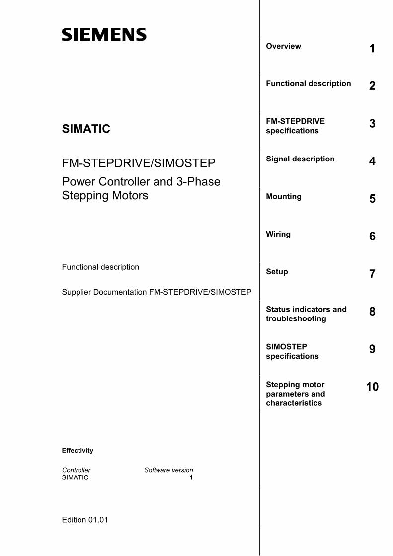
SIMATIC
FM-STEPDRIVE/SIMOSTEPPower Controller and 3-PhaseStepping Motors
Functional description
Supplier Documentation FM-STEPDRIVE/SIMOSTEP
Effectivity
Controller Software versionSIMATIC 1
Edition 01.01
SINUMERIK® Documentation
Printing history
Brief details of this editor and previous editions are listed below.
The status of each edition is shown by the code in the "Remarks" column.
Status code in "Remarks" column:
A .... New documentation
B .... Unrevised reprint with new order No.
C .... Revised edition with new status
If factual changes have been made on the page since the last editon, this isindicated by a new edition coding in the header on that page.
Edition Order No. Remarks01.96 6SN1197-0AA70-0YP0 A01.97 6SN1197-0AA70-0YP1 C01.97 6SN1197-0AA70-0YP2 C11.98 6SN1197-0AA70-0YP3 C01.01 6SN1197-0AA70-0YP4 C
This documentation was created using WinWord V 7.0,Designer V 7 and Doc-To-Help V 1.6.The reproduction, transmission or use of this document or its contents is notpermitted without express written authority. Offanders will be liable for damages.All rights, including rights created by patent grant or registration of a utility modal ordesign, are reserved.
© Siemens AG 1998. All Rights Reserved.
Other functions not described in this documentation might be executable in thecontrol. This does not, however, represent an obligation to supply such functionswith a new control or when servicing.
The contents of this publication has been verified for correspondence with thehardware and software described. Nevertheless there may still be somedeviations. The information contained herein is verified on a regular basis, andany corrections will be included in the subsequent editions. We should appreciateany suggestions for improvement.
Subject to technical modifications.
Order no. 6SN1197-0AA70-0YP4Printed in the Federal Republic of Germany
Siemens AG
I
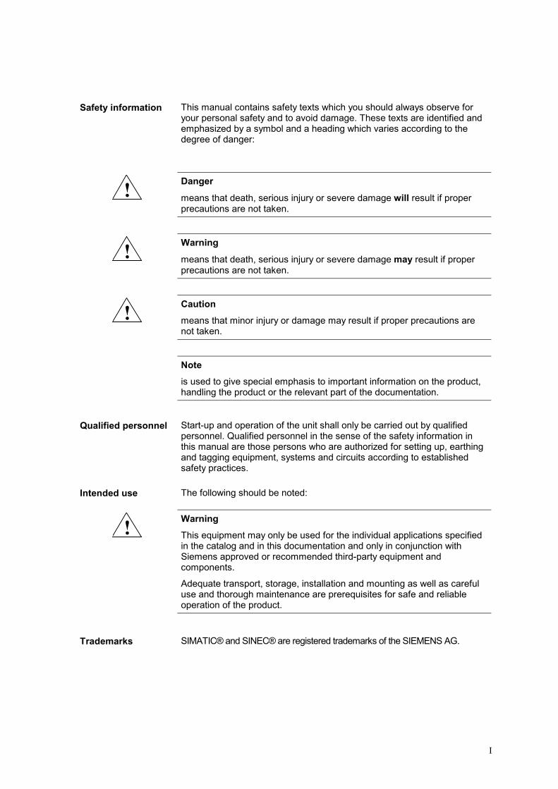
Safety information This manual contains safety texts which you should always observe foryour personal safety and to avoid damage. These texts are identified andemphasized by a symbol and a heading which varies according to thedegree of danger:
! Danger
means that death, serious injury or severe damage will result if properprecautions are not taken.
! Warning
means that death, serious injury or severe damage may result if properprecautions are not taken.
! Cautionmeans that minor injury or damage may result if proper precautions arenot taken.
Noteis used to give special emphasis to important information on the product,handling the product or the relevant part of the documentation.
Qualified personnel Start-up and operation of the unit shall only be carried out by qualifiedpersonnel. Qualified personnel in the sense of the safety information inthis manual are those persons who are authorized for setting up, earthingand tagging equipment, systems and circuits according to establishedsafety practices.
Intended use The following should be noted:
! WarningThis equipment may only be used for the individual applications specifiedin the catalog and in this documentation and only in conjunction withSiemens approved or recommended third-party equipment andcomponents.
Adequate transport, storage, installation and mounting as well as carefuluse and thorough maintenance are prerequisites for safe and reliableoperation of the product.
Trademarks SIMATIC® and SINEC® are registered trademarks of the SIEMENS AG.

II
01.01 Contents
© Siemens AG 1998 All Rights Reserved FM-STEPDRIVE/SIMOSTEP (FB) III
ContentsPage
Overview....................................................................................................................................1-1
Functional description .............................................................................................................2-1
FM-STEPDRIVE specifications ................................................................................................3-1
3.1 Electrical data....................................................................................................3-2
3.2 Mechanical data ................................................................................................3-5
3.3 Ambient conditions............................................................................................3-5
3.4 Applicable standards, regulations, laws ............................................................3-6
Signal description.....................................................................................................................4-1
4.1 Pulse interface ..................................................................................................4-2
4.2 Signal interface..................................................................................................4-3
4.3 Signal timing diagrams......................................................................................4-4
Mounting....................................................................................................................................5-1
Wiring.........................................................................................................................................6-1
6.1 FM-STEPDRIVE and SIMOSTEP wiring ..........................................................6-2
6.2 Wiring example for FM-353 and FM-NC/FM357...............................................6-4
6.3 Wiring layout for control cabinet........................................................................6-6
6.4 Network wiring for several axes ........................................................................6-7
6.5 Operating an axis in a safe working area........................................................6-10
6.6 Accessories.....................................................................................................6-12
Setup ..........................................................................................................................................7-1
Status indicators and troubleshooting...................................................................................8-1
SIMOSTEP specifications ........................................................................................................9-1
Stepping motor parameters and characteristics .................................................................10-1
10.1 Basic concepts ................................................................................................10-2
10.2 Torque characteristics.....................................................................................10-3

IV

© Siemens AG 1998 All Rights Reserved FM-STEPDRIVE/SIMOSTEP (FB) 1-1
Overview 1
1 Overview 01.01
© Siemens AG 1998 All Rights Reserved1-2 FM-STEPDRIVE/SIMOSTEP (FB)
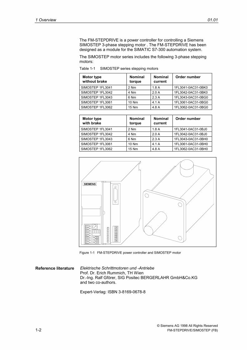
The FM-STEPDRIVE is a power controller for controlling a SiemensSIMOSTEP 3-phase stepping motor . The FM-STEPDRIVE has beendesigned as a module for the SIMATIC S7-300 automation system.
The SIMOSTEP motor series includes the following 3-phase steppingmotors:Table 1-1 SIMOSTEP series stepping motors
Motor typewithout brake
Nominaltorque
Nominalcurrent
Order number
SIMOSTEP 1FL3041 2 Nm 1.8 A 1FL3041-0AC31-0BK0SIMOSTEP 1FL3042 4 Nm 2.0 A 1FL3042-0AC31-0BK0SIMOSTEP 1FL3043 6 Nm 2.3 A 1FL3043-0AC31-0BG0SIMOSTEP 1FL3061 10 Nm 4.1 A 1FL3061-0AC31-0BG0SIMOSTEP 1FL3062 15 Nm 4.8 A 1FL3062-0AC31-0BG0
Motor typewith brake
Nominaltorque
Nominalcurrent
Order number
SIMOSTEP 1FL3041 2 Nm 1.8 A 1FL3041-0AC31-0BJ0SIMOSTEP 1FL3042 4 Nm 2.0 A 1FL3042-0AC31-0BJ0SIMOSTEP 1FL3043 6 Nm 2.3 A 1FL3043-0AC31-0BH0SIMOSTEP 1FL3061 10 Nm 4.1 A 1FL3061-0AC31-0BH0SIMOSTEP 1FL3062 15 Nm 4.8 A 1FL3062-0AC31-0BH0
Figure 1-1 FM-STEPDRIVE power controller and SIMOSTEP motor
Reference literature Elektrische Schrittmotoren und -AntriebeProf. Dr. Erich Rummich, TH WienDr.-Ing. Ralf Gförer, SIG Positec BERGERLAHR GmbH&Co.KGand two co-authors.
Expert-Verlag: ISBN 3-8169-0678-8

© Siemens AG 1998 All Rights Reserved FM-STEPDRIVE/SIMOSTEP (FB) 2-1
Functional description 2
2 Functional description 01.01
© Siemens AG 1998 All Rights Reserved2-2 FM-STEPDRIVE/SIMOSTEP (FB)
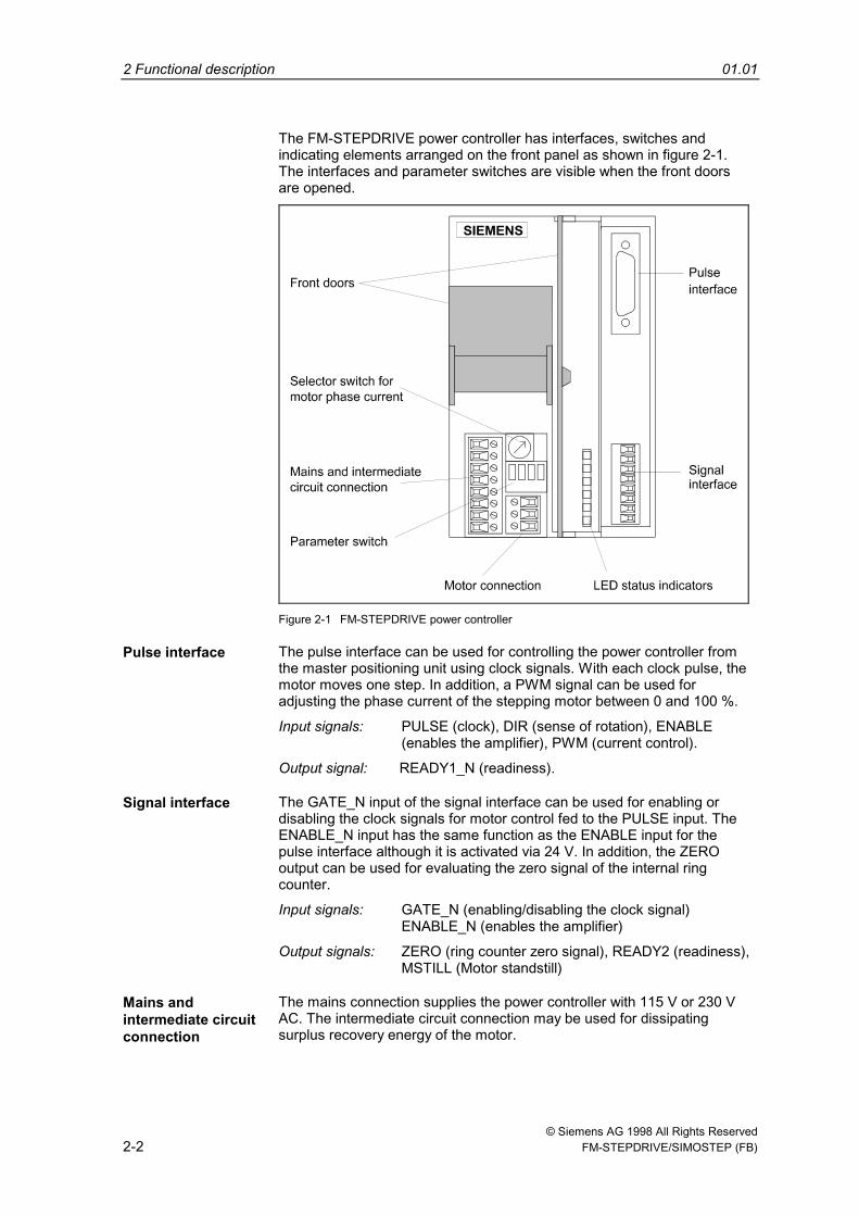
The FM-STEPDRIVE power controller has interfaces, switches andindicating elements arranged on the front panel as shown in figure 2-1.The interfaces and parameter switches are visible when the front doorsare opened.
Figure 2-1 FM-STEPDRIVE power controller
Pulse interface The pulse interface can be used for controlling the power controller fromthe master positioning unit using clock signals. With each clock pulse, themotor moves one step. In addition, a PWM signal can be used foradjusting the phase current of the stepping motor between 0 and 100 %.
Input signals: PULSE (clock), DIR (sense of rotation), ENABLE(enables the amplifier), PWM (current control).
Output signal: READY1_N (readiness).
Signal interface The GATE_N input of the signal interface can be used for enabling ordisabling the clock signals for motor control fed to the PULSE input. TheENABLE_N input has the same function as the ENABLE input for thepulse interface although it is activated via 24 V. In addition, the ZEROoutput can be used for evaluating the zero signal of the internal ringcounter.
Input signals: GATE_N (enabling/disabling the clock signal)ENABLE_N (enables the amplifier)
Output signals: ZERO (ring counter zero signal), READY2 (readiness),MSTILL (Motor standstill)
Mains andintermediate circuitconnection
The mains connection supplies the power controller with 115 V or 230 VAC. The intermediate circuit connection may be used for dissipatingsurplus recovery energy of the motor.
01.01 2 Functional description
© Siemens AG 1998 All Rights Reserved FM-STEPDRIVE/SIMOSTEP (FB) 2-3
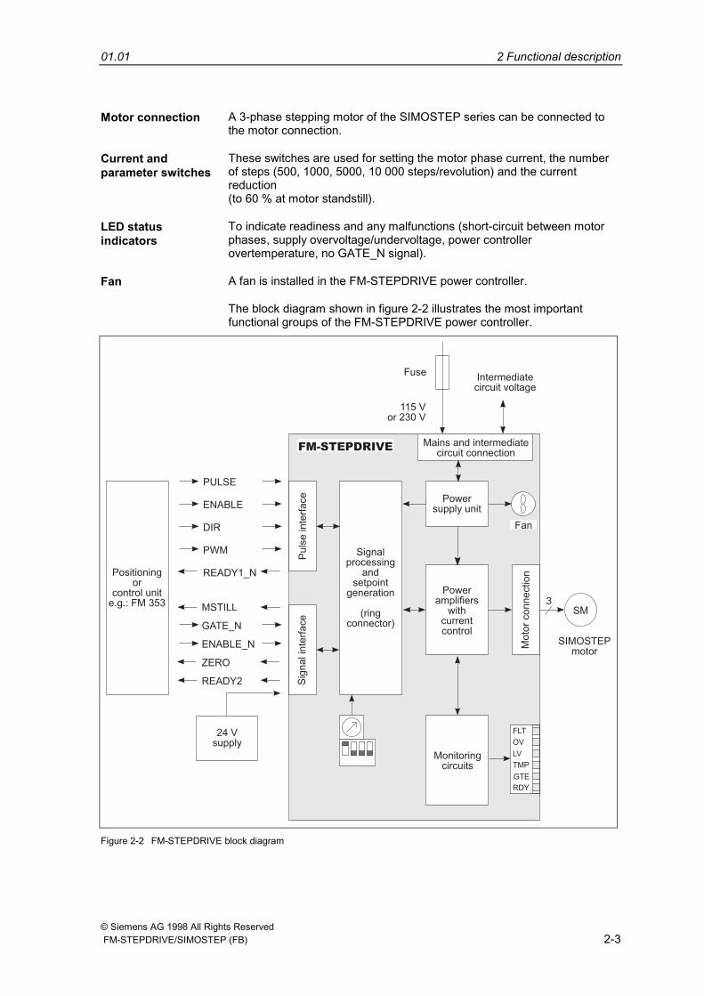
Motor connection A 3-phase stepping motor of the SIMOSTEP series can be connected tothe motor connection.
Current andparameter switches
These switches are used for setting the motor phase current, the numberof steps (500, 1000, 5000, 10 000 steps/revolution) and the currentreduction(to 60 % at motor standstill).
LED statusindicators
To indicate readiness and any malfunctions (short-circuit between motorphases, supply overvoltage/undervoltage, power controllerovertemperature, no GATE_N signal).
Fan A fan is installed in the FM-STEPDRIVE power controller.
The block diagram shown in figure 2-2 illustrates the most importantfunctional groups of the FM-STEPDRIVE power controller.
115 Vor 230 V
Intermediatecircuit voltage
Fuse
FM-STEPDRIVE
3
24 Vsupply
PULSE
ENABLE
DIR
PWM
READY1_NPositioningor
control unite.g.: FM 353
SIMOSTEPmotor
SM
Mains and intermediatecircuit connection
Powersupply unit
Poweramplifiers
withcurrentcontrol
Monitoringcircuits
Signalprocessing
andsetpoint
generation
(ringconnector)
Fan
FLT
OV
LV
TMP
RDY
Puls
ein
terf
ace
Sig
na
lin
terf
ace
Mo
tor
co
nn
ectio
n
READY2
ZERO
GATE_N
MSTILL
ENABLE_N
GTE
Figure 2-2 FM-STEPDRIVE block diagram

2 Functional description 01.01
© Siemens AG 1998 All Rights Reserved2-4 FM-STEPDRIVE/SIMOSTEP (FB)
© Siemens AG 1998 All Rights Reserved FM-STEPDRIVE/SIMOSTEP (FB) 3-1
FM-STEPDRIVE specifications
3.1 Electrical data.......................................................................... 3-2
3.2 Mechanical data ...................................................................... 3-5
3.3 Ambient conditions.................................................................. 3-5
3.4 Applicable standards, regulations, laws .................................. 3-6
3
3 FM-STEPDRIVE specifications 01.01
© Siemens AG 1998 All Rights Reserved3-2 FM-STEPDRIVE/SIMOSTEP (FB)
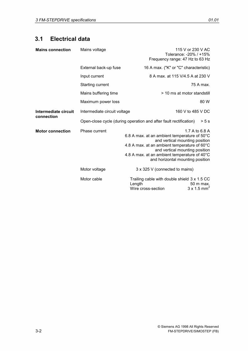
3.1 Electrical dataMains connection Mains voltage 115 V or 230 V AC
Tolerance: -20% / +15%Frequency range: 47 Hz to 63 Hz
External back-up fuse 16 A max. ("K" or "C" characteristic)
Input current 8 A max. at 115 V/4.5 A at 230 V
Starting current 75 A max.
Mains buffering time > 10 ms at motor standstill
Maximum power loss 80 W
Intermediate circuitconnection
Intermediate circuit voltage 160 V to 485 V DC
Open-close cycle (during operation and after fault rectification) > 5 s
Motor connection Phase current 1.7 A to 6.8 A6.8 A max. at an ambient temperature of 50°C
and vertical mounting position4.8 A max. at an ambient temperature of 60°C
and vertical mounting position4.8 A max. at an ambient temperature of 40°C
and horizontal mounting position
Motor voltage 3 x 325 V (connected to mains)
Motor cable Trailing cable with double shield 3 x 1.5 CCLength 50 m max.Wire cross-section 3 x 1.5 mm2
01.01 3 FM-STEPDRIVE specifications
© Siemens AG 1998 All Rights Reserved FM-STEPDRIVE/SIMOSTEP (FB) 3-3
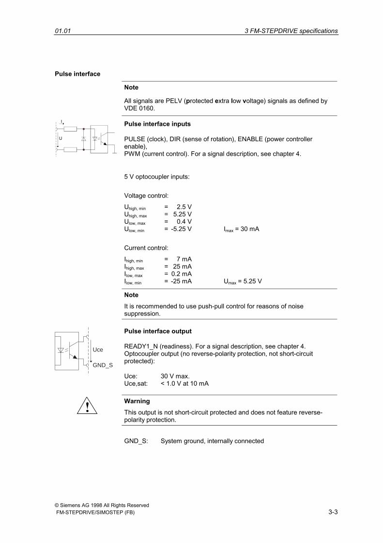
Pulse interface
Note
All signals are PELV (protected extra low voltage) signals as defined byVDE 0160.
Pulse interface inputs
PULSE (clock), DIR (sense of rotation), ENABLE (power controllerenable),PWM (current control). For a signal description, see chapter 4.
5 V optocoupler inputs:
Voltage control:
Uhigh, min = 2.5 VUhigh, max = 5.25 VUlow, max = 0.4 VUlow, min = -5.25 V Imax = 30 mA
Current control:
Ihigh, min = 7 mAIhigh, max = 25 mAIlow, max = 0.2 mAIlow, min = -25 mA Umax = 5.25 V
NoteIt is recommended to use push-pull control for reasons of noisesuppression.
Uce
GND_S
Pulse interface output
READY1_N (readiness). For a signal description, see chapter 4.Optocoupler output (no reverse-polarity protection, not short-circuitprotected):
Uce: 30 V max.Uce,sat: < 1.0 V at 10 mA
! WarningThis output is not short-circuit protected and does not feature reverse-polarity protection.
GND_S: System ground, internally connected
3 FM-STEPDRIVE specifications 01.01
© Siemens AG 1998 All Rights Reserved3-4 FM-STEPDRIVE/SIMOSTEP (FB)
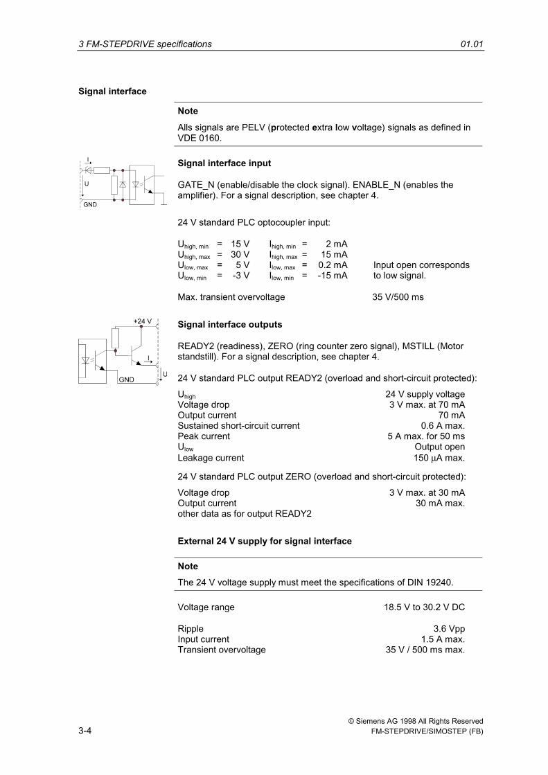
Signal interface
Note
Alls signals are PELV (protected extra low voltage) signals as defined inVDE 0160.
Signal interface input
GATE_N (enable/disable the clock signal). ENABLE_N (enables theamplifier). For a signal description, see chapter 4.
24 V standard PLC optocoupler input:
Uhigh, min = 15 V Ihigh, min = 2 mAUhigh, max = 30 V Ihigh, max = 15 mAUlow, max = 5 V Ilow, max = 0.2 mA Input open correspondsUlow, min = -3 V Ilow, min = -15 mA to low signal.
Max. transient overvoltage 35 V/500 ms
Signal interface outputs
READY2 (readiness), ZERO (ring counter zero signal), MSTILL (Motorstandstill). For a signal description, see chapter 4.
24 V standard PLC output READY2 (overload and short-circuit protected):
Uhigh 24 V supply voltageVoltage drop 3 V max. at 70 mAOutput current 70 mASustained short-circuit current 0.6 A max.Peak current 5 A max. for 50 msUlow Output openLeakage current 150 µA max.
24 V standard PLC output ZERO (overload and short-circuit protected):
Voltage drop 3 V max. at 30 mAOutput current 30 mA max.other data as for output READY2
External 24 V supply for signal interface
NoteThe 24 V voltage supply must meet the specifications of DIN 19240.
Voltage range 18.5 V to 30.2 V DC
Ripple 3.6 VppInput current 1.5 A max.Transient overvoltage 35 V / 500 ms max.
01.01 3 FM-STEPDRIVE specifications
© Siemens AG 1998 All Rights Reserved FM-STEPDRIVE/SIMOSTEP (FB) 3-5
3.2 Mechanical dataDimensions (H x W x D) 125 x 80 x 117 mm
Weight 890 g
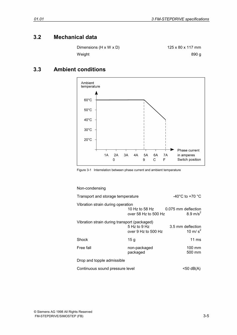
3.3 Ambient conditions
Figure 3-1 Interrelation between phase current and ambient temperature
Non-condensing
Transport and storage temperature -40°C to +70 °C
Vibration strain during operation10 Hz to 58 Hz 0.075 mm deflectionover 58 Hz to 500 Hz 8.9 m/s2
Vibration strain during transport (packaged)5 Hz to 9 Hz 3.5 mm deflectionover 9 Hz to 500 Hz 10 m/ s2
Shock 15 g 11 ms
Free fall non-packaged 100 mmpackaged 500 mm
Drop and topple admissible
Continuous sound pressure level <50 dB(A)
3 FM-STEPDRIVE specifications 01.01
© Siemens AG 1998 All Rights Reserved3-6 FM-STEPDRIVE/SIMOSTEP (FB)
3.4 Applicable standards, regulations, laws
The following standards, regulations and laws must be observedwhen operating the FM-STEPDRIVE:
• DIN EN 60204 Part 1 (VDE 0113)Electrical equipment of machines
• DIN VDE 0100 Erection of power installations withnominal voltages up to 1000 V
• DIN VDE 0106 Protection against electric shock
• DIN VDE 0470 (and: IEC 529) IP degrees of protection
• DIN VDE 0875 (EN 55011) Radio interference suppression ofelectrical appliances and systems
• DIN EN 954-1 Safety of machinesSafety-related parts ofcontrol systemsGeneral design guidelines
If you intend to use the FM-STEPDRIVE power drive in a residential area,the limit values of the following standards must also be observed:
• EN 60555 Disturbances in electricity supplynetworks caused by householdappliances and similar equipment
• EN 55022, Class B Limit values and measurementmethods for information technologyequipment
• DIN EN 61000 Part 3-2 Electromagnetic compatibility
In case of high interference levels, additional measures must be taken.We recommend to provide for EMC design of cabinets, e.g. 8MCcabinets,(-> catalog NV 21).
The following standards, regulations and laws have been observedwhen developing the FM-STEPDRIVE:
• UL 508 Industrial control equipment
• CSA C22.2 No 142 Process control equipment
© Siemens AG 1998 All Rights Reserved FM-STEPDRIVE/SIMOSTEP (FB) 4-1
Signal description
4.1 Pulse interface ........................................................................ 4-2
4.2 Signal interface........................................................................ 4-3
4.3 Signal timing diagrams............................................................ 4-4
4
4 Signal description 01.01
© Siemens AG 1998 All Rights Reserved4-2 FM-STEPDRIVE/SIMOSTEP (FB)
The signals and timing diagrams for the pulse and signal interfaces aredescribed in the following sections.
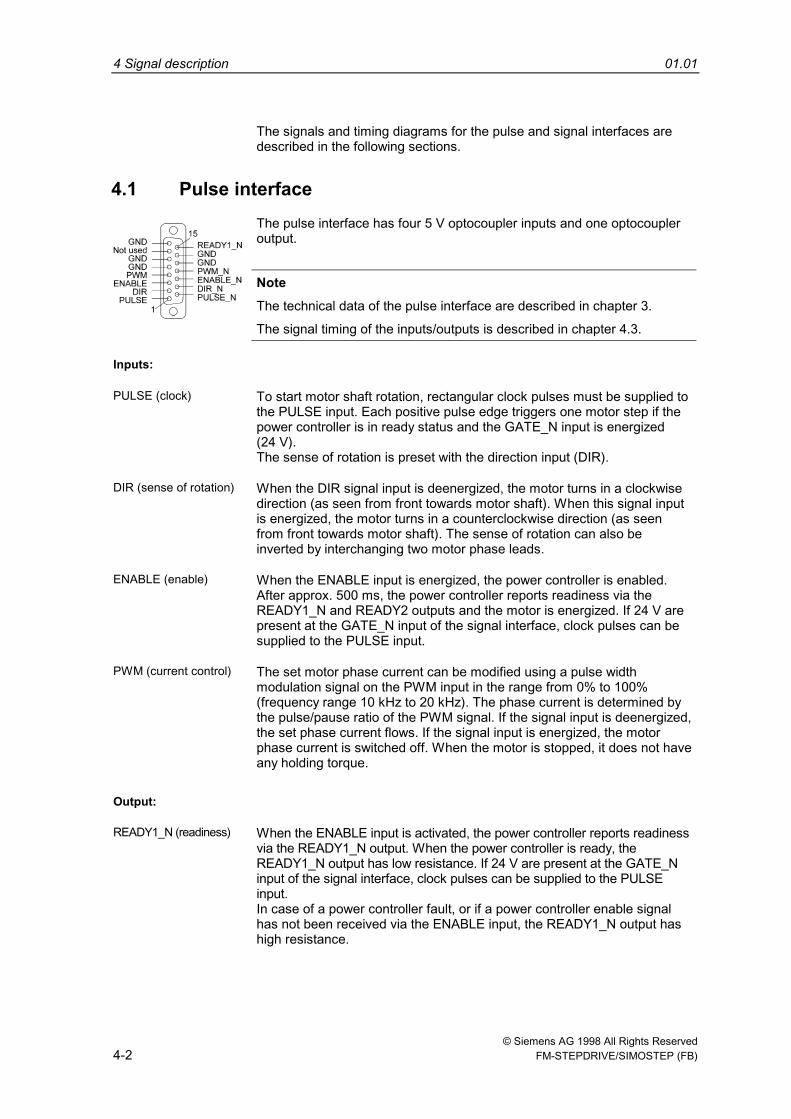
4.1 Pulse interfaceThe pulse interface has four 5 V optocoupler inputs and one optocoupleroutput.
NoteThe technical data of the pulse interface are described in chapter 3.
The signal timing of the inputs/outputs is described in chapter 4.3.
Inputs:
PULSE (clock) To start motor shaft rotation, rectangular clock pulses must be supplied tothe PULSE input. Each positive pulse edge triggers one motor step if thepower controller is in ready status and the GATE_N input is energized(24 V).The sense of rotation is preset with the direction input (DIR).
DIR (sense of rotation) When the DIR signal input is deenergized, the motor turns in a clockwisedirection (as seen from front towards motor shaft). When this signal inputis energized, the motor turns in a counterclockwise direction (as seenfrom front towards motor shaft). The sense of rotation can also beinverted by interchanging two motor phase leads.
ENABLE (enable) When the ENABLE input is energized, the power controller is enabled.After approx. 500 ms, the power controller reports readiness via theREADY1_N and READY2 outputs and the motor is energized. If 24 V arepresent at the GATE_N input of the signal interface, clock pulses can besupplied to the PULSE input.
PWM (current control) The set motor phase current can be modified using a pulse widthmodulation signal on the PWM input in the range from 0% to 100%(frequency range 10 kHz to 20 kHz). The phase current is determined bythe pulse/pause ratio of the PWM signal. If the signal input is deenergized,the set phase current flows. If the signal input is energized, the motorphase current is switched off. When the motor is stopped, it does not haveany holding torque.
Output:
READY1_N (readiness) When the ENABLE input is activated, the power controller reports readinessvia the READY1_N output. When the power controller is ready, theREADY1_N output has low resistance. If 24 V are present at the GATE_Ninput of the signal interface, clock pulses can be supplied to the PULSEinput.In case of a power controller fault, or if a power controller enable signalhas not been received via the ENABLE input, the READY1_N output hashigh resistance.
01.01 4 Signal description
© Siemens AG 1998 All Rights Reserved FM-STEPDRIVE/SIMOSTEP (FB) 4-3
4.2 Signal interface
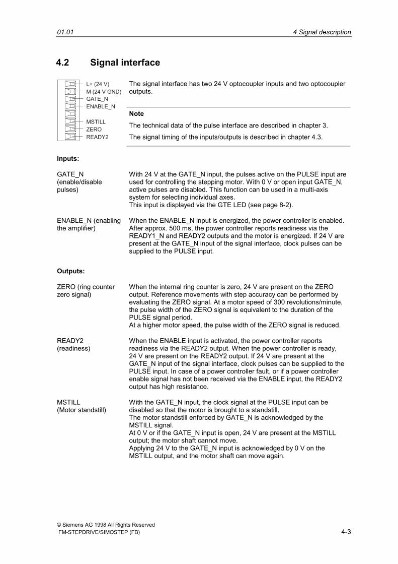
The signal interface has two 24 V optocoupler inputs and two optocoupleroutputs.
READY2
ZERO
MSTILL
GATE_N
M (24 V GND)
L+ (24 V)
ENABLE_N
NoteThe technical data of the pulse interface are described in chapter 3.
The signal timing of the inputs/outputs is described in chapter 4.3.
Inputs:
GATE_N(enable/disablepulses)
With 24 V at the GATE_N input, the pulses active on the PULSE input areused for controlling the stepping motor. With 0 V or open input GATE_N,active pulses are disabled. This function can be used in a multi-axissystem for selecting individual axes.This input is displayed via the GTE LED (see page 8-2).
ENABLE_N (enablingthe amplifier)
When the ENABLE_N input is energized, the power controller is enabled.After approx. 500 ms, the power controller reports readiness via theREADY1_N and READY2 outputs and the motor is energized. If 24 V arepresent at the GATE_N input of the signal interface, clock pulses can besupplied to the PULSE input.
Outputs:
ZERO (ring counterzero signal)
When the internal ring counter is zero, 24 V are present on the ZEROoutput. Reference movements with step accuracy can be performed byevaluating the ZERO signal. At a motor speed of 300 revolutions/minute,the pulse width of the ZERO signal is equivalent to the duration of thePULSE signal period.At a higher motor speed, the pulse width of the ZERO signal is reduced.
READY2(readiness)
When the ENABLE input is activated, the power controller reportsreadiness via the READY2 output. When the power controller is ready,24 V are present on the READY2 output. If 24 V are present at theGATE_N input of the signal interface, clock pulses can be supplied to thePULSE input. In case of a power controller fault, or if a power controllerenable signal has not been received via the ENABLE input, the READY2output has high resistance.
MSTILL(Motor standstill)
With the GATE_N input, the clock signal at the PULSE input can bedisabled so that the motor is brought to a standstill.The motor standstill enforced by GATE_N is acknowledged by theMSTILL signal.At 0 V or if the GATE_N input is open, 24 V are present at the MSTILLoutput; the motor shaft cannot move.Applying 24 V to the GATE_N input is acknowledged by 0 V on theMSTILL output, and the motor shaft can move again.
4 Signal description 01.01
© Siemens AG 1998 All Rights Reserved4-4 FM-STEPDRIVE/SIMOSTEP (FB)
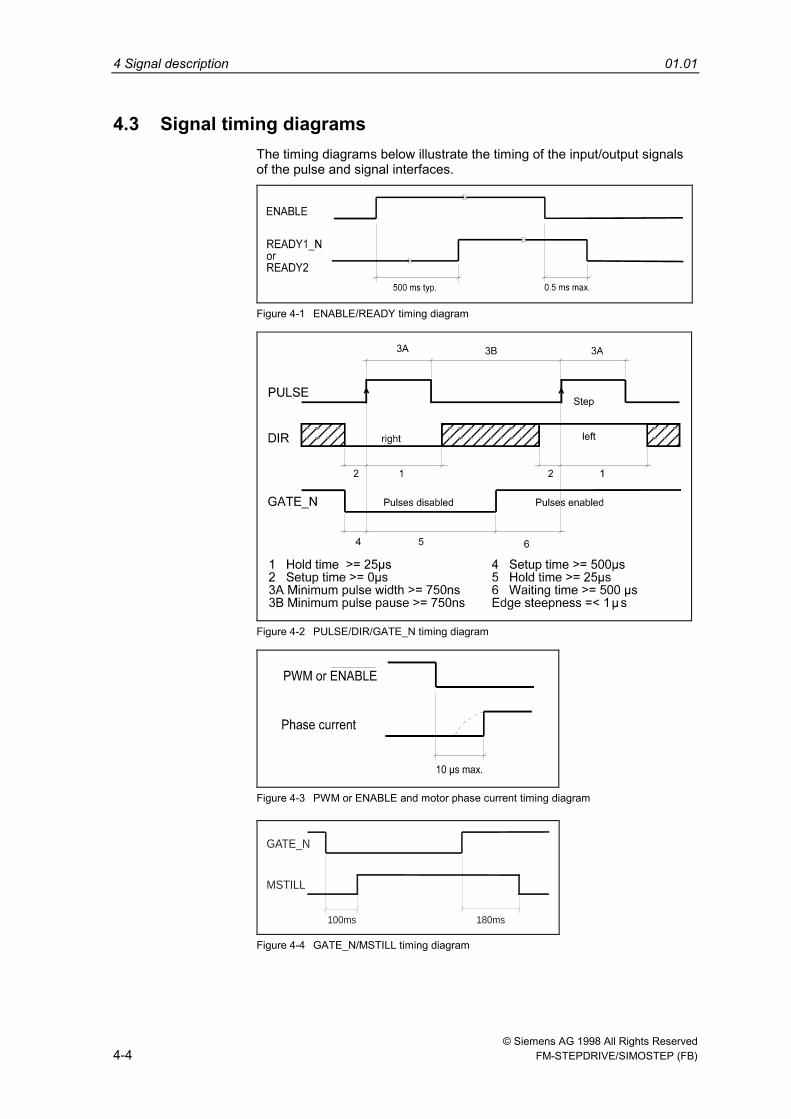
4.3 Signal timing diagramsThe timing diagrams below illustrate the timing of the input/output signalsof the pulse and signal interfaces.
Figure 4-1 ENABLE/READY timing diagram
Figure 4-2 PULSE/DIR/GATE_N timing diagram
Figure 4-3 PWM or ENABLE and motor phase current timing diagram
100ms 180ms
GATE_N
MSTILL
Figure 4-4 GATE_N/MSTILL timing diagram

© Siemens AG 1998 All Rights Reserved FM-STEPDRIVE/SIMOSTEP (FB) 5-1
Mounting 5
5 Mounting 01.01
© Siemens AG 1998 All Rights Reserved5-2 FM-STEPDRIVE/SIMOSTEP (FB)
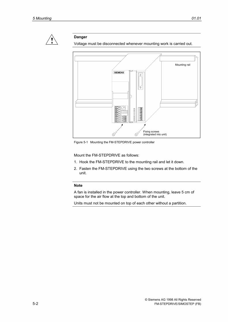
! DangerVoltage must be disconnected whenever mounting work is carried out.
Figure 5-1 Mounting the FM-STEPDRIVE power controller
Mount the FM-STEPDRIVE as follows:
1. Hook the FM-STEPDRIVE to the mounting rail and let it down.
2. Fasten the FM-STEPDRIVE using the two screws at the bottom of theunit.
NoteA fan is installed in the power controller. When mounting, leave 5 cm ofspace for the air flow at the top and bottom of the unit.
Units must not be mounted on top of each other without a partition.
© Siemens AG 1998 All Rights Reserved FM-STEPDRIVE/SIMOSTEP (FB) 6-1
Wiring
6.1 FM-STEPDRIVE and SIMOSTEP wiring ................................ 6-2
6.2 Wiring example for FM-353 and FM-NC/FM357..................... 6-4
6.3 Wiring layout for control cabinet.............................................. 6-6
6.4 Network wiring for several axes .............................................. 6-7
6.5 Operating an axis in a safe working area................................ 6-10
6.6 Accessories............................................................................. 6-12
6
6 Wiring 01.01
© Siemens AG 1998 All Rights Reserved6-2 FM-STEPDRIVE/SIMOSTEP (FB)
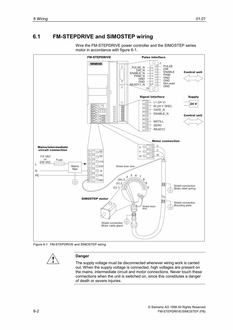
6.1 FM-STEPDRIVE and SIMOSTEP wiringWire the FM-STEPDRIVE power controller and the SIMOSTEP seriesmotor in accordance with figure 6-1.
Motor connection
Mains/intermediate
circuit connection
Pulse interface
Control unit
Control unit
Supply
SIMOSTEP motor
115 VACor
230 VAC
N
PE
Fuse
DC+
DC-
115
230
N
PE
MS
UU
VV
WW
Shield drain wire
Shield drainwire
(W) 3
(V) 2
(U) 1
45 6 7
8
9
0
Signal interface
FM-STEPDRIVE
PULSE_NDIR_N
ENABLE_NPWM_N
GNDGND
READY1_N
PULSEDIRENABLEPWMGNDGNDNot usedGND
1
15
24 V
L
Shield connectionStrain relief spring
Shield connectionMounting plate
Shield connectionMotor cable gland
Mainsfilter
READY2
ZERO
MSTILL
GATE_N
M (24 V GND)
L+ (24 V)
ENABLE_N
Figure 6-1 FM-STEPDRIVE and SIMOSTEP wiring
! DangerThe supply voltage must be disconnected whenever wiring work is carriedout. When the supply voltage is connected, high voltages are present onthe mains, intermediate circuit and motor connections. Never touch theseconnections when the unit is switched on, since this constitutes a dangerof death or severe injuries.
01.01 6 Wiring
© Siemens AG 1998 All Rights Reserved FM-STEPDRIVE/SIMOSTEP (FB) 6-3
Mains connection The unit must be protected by an external 16 a type Kor C standard fuse.
! DangerIf the neutral conductor is connected, the three-phase power supplyrequires that the individual phases and neutral be connected/disconnectedsimultaneously. In order to avoid overvoltage.
In order to fulfil the EMC requirements, a mains filter must be inserted intothe mains supply line (see chapter 6.4).
Intermediate circuitconnection
With multi-axis wiring and single-phase mains connection, theintermediate circuit connections DC+ and DC- can be interconnected forenergy exchange between the power controllers. This is recommendedwhen considerable masses must be accelerated and decelerated within ashort time.
Motor wiring For the cable connection in the motor terminal panel, unscrew the fourPhillips screws of the terminal panel.
The shield drain wire of the motor cable must be connected on the motorand the device end as shown in figure 6-1.
The protective conductor connection on the motor is usually establishedvia the motor fastening components. If this connection should beinsufficient, the protective conductor may be connected to the externalterminal of the motor.
A shielded 3-wire standard cable can be used for connecting the motor(see accessory table, chapter 6.6).
The cable shield must be clamped with the motor cable gland on themotor and connected to the strain relief spring on the power controller(remove the sheath at the strain relief element).
Behind the strain relief element, the cable sheath should reach as far aspossible to the motor connection on the FM-STEPDRIVE.
At the cable entry into the cabinet, the cable shield must be connected toa grounded shield terminal (remove the sheath at the terminal).
Pulse interface Ready-made cables with sub-D connectors can be used for connectingthe pulse interface of the FM-STEPDRIVE power controller to thepositioning module FM-353 or the FM-NC/FM357 controller (seeaccessory table, chapter 6.6).For a wiring example, see chapter 6.2.
Signal interface The signal interface must be supplied with 24 V DC from an externalpower supply unit.
The 24 V supply must meet the requirements of the DIN VDE 19240standard. For a wiring example, see chapter 6.2.
6 Wiring 01.01
© Siemens AG 1998 All Rights Reserved6-4 FM-STEPDRIVE/SIMOSTEP (FB)
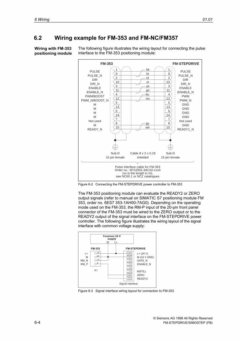
6.2 Wiring example for FM-353 and FM-NC/FM357Wiring with FM-353positioning module
The following figure illustrates the wiring layout for connecting the pulseinterface to the FM-353 positioning module:
Pulse interface cable for FM-353Order no.: 6FX2002-3AC02-1xx0
(xx is the length in m),see NC60.1 or NCZ catalogues
PULSE_N PULSE_NPULSE
FM-353 FM-STEPDRIVE
PULSE1 1bk9 9br2 2rd10 10or3 3ye11 11gn4 4bu12 12vio5 513 136 614 147 78 8gy15 15wh
DIR DIRDIR_N DIR_N
ENABLE ENABLEENABLE_N ENABLE_N
PWM/BOOST PWMPWM_N/BOOST_N PWM_N
M GNDGNDGNDGND
MMM
Not used Not usedM GND
READY_N
Sub-D Sub-DCable 8 x 2 x 0.1815 pin female 15 pin femaleshielded
READY1_N
Figure 6-2 Connecting the FM-STEPDRIVE power controller to FM-353
The FM-353 positioning module can evaluate the READY2 or ZEROoutput signals (refer to manual on SIMATIC S7 positioning module FM353, order no. 6ES7 353-1AH00-7AG0). Depending on the operatingmode used on the FM-353, the RM-P input of the 20-pin front panelconnector of the FM-353 must be wired to the ZERO output or to theREADY2 output of the signal interface on the FM-STEPDRIVE powercontroller. The following figure illustrates the wiring layout of the signalinterface with common voltage supply:
FM-STEPDRIVEFM-353
Common 24 Vsupply
Signal interface
19
20
10
9
X1
L+
L+M
M
RM_N
RM_P
READY2
ZERO
MSTILL
GATE_N
M (24 V GND)
L+ (24 V)
ENABLE_N
Figure 6-3 Signal interface wiring layout for connection to FM-353
01.01 6 Wiring
© Siemens AG 1998 All Rights Reserved FM-STEPDRIVE/SIMOSTEP (FB) 6-5
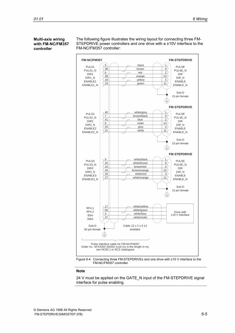
Multi-axis wiringwith FM-NC/FM357controller
The following figure illustrates the wiring layout for connecting three FM-STEPDRIVE power controllers and one drive with a ±10V interface to theFM-NC/FM357 controller:
PULS1_N
PULS2_N
PULS3_N
RF4.2
PULSE_N
PULSE_N
PULSE_N
PULS1
PULS2
PULS3
RF4.1
FM-NC/FM357 FM-STEPDRIVE
FM-STEPDRIVE
FM-STEPDRIVE
PULSE
PULSE
PULSE
5
40
9
17
1
1
1
black
white/grey
white/black
white/yellow
38
7
42
50
9
9
9
brown
brown/black
white/brown
white/green
6
41
10
4
2
2
2
red
blue
brown/red
white/blue
39
8
43
37
10
10
10
orange
violet
brown/orange
white/violet
18
20
26
3
3
3
yellow
grey
white/red
19
21
27
11
11
11
green
white
white/orange
DIR1
DIR2
DIR3
BS4
DIR
DIR
DIR
DIR1_N
DIR2_N
DIR3_N
SW4
DIR_N
DIR_N
DIR_N
ENABLE1
ENABLE2
ENABLE3
ENABLE
ENABLE
ENABLE
ENABLE1_N
ENABLE2_N
ENABLE3_N
ENABLE_N
ENABLE_N
ENABLE_N
Sub-D
Sub-D
Sub-D
Sub-D50 pin female
15 pin female
15 pin female
15 pin female
Drive with±10 V interface
Cable 12 x 2 x 0.14shielded
Pulse interface cable for FM-NC/FM357Order no.: 6FX2002-3AD02-1xx0 (xx is the length in m),
see NC60.1 or NCZ catalogues
Figure 6-4 Connecting three FM-STEPDRIVEs and one drive with ±10 V interface to theFM-NC/FM357 controller
Note24 V must be applied on the GATE_N input of the FM-STEPDRIVE signalinterface for pulse enabling.
6 Wiring 01.01
© Siemens AG 1998 All Rights Reserved6-6 FM-STEPDRIVE/SIMOSTEP (FB)
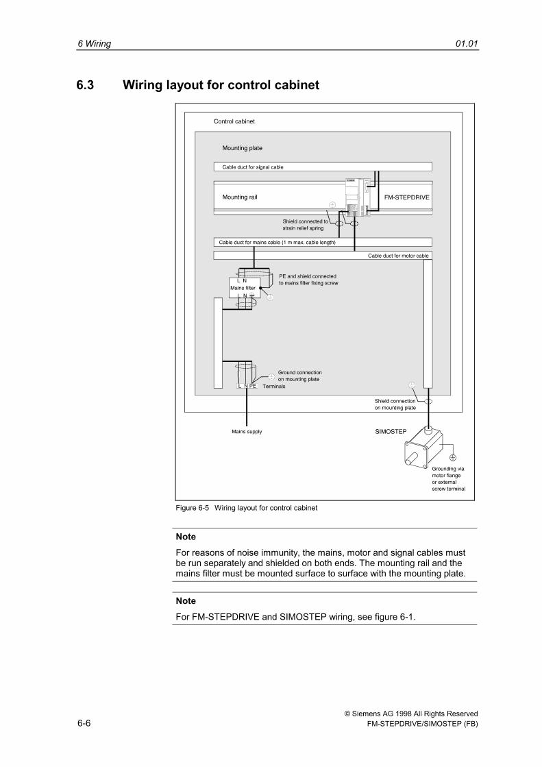
6.3 Wiring layout for control cabinet
Figure 6-5 Wiring layout for control cabinet
NoteFor reasons of noise immunity, the mains, motor and signal cables mustbe run separately and shielded on both ends. The mounting rail and themains filter must be mounted surface to surface with the mounting plate.
NoteFor FM-STEPDRIVE and SIMOSTEP wiring, see figure 6-1.
01.01 6 Wiring
© Siemens AG 1998 All Rights Reserved FM-STEPDRIVE/SIMOSTEP (FB) 6-7
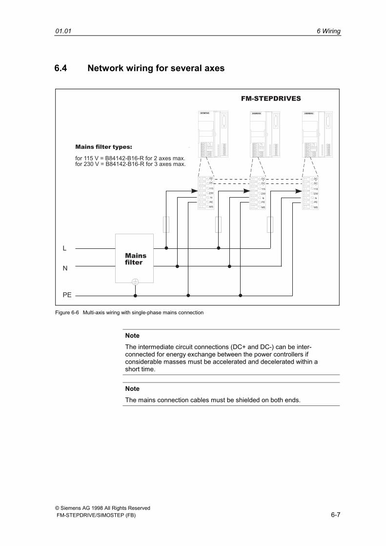
6.4 Network wiring for several axes
FM-STEPDRIVES
DC+
DC-
115
230
N
PE
MS
DC+
DC-
115
230
N
PE
MS
DC+
DC-
115
230
N
PE
MS
Mainsfilter
L
N
PE
Mains filter types:
for 115 V = B84142-B16-R for 2 axes max.for 230 V = B84142-B16-R for 3 axes max.
Figure 6-6 Multi-axis wiring with single-phase mains connection
NoteThe intermediate circuit connections (DC+ and DC-) can be inter-connected for energy exchange between the power controllers ifconsiderable masses must be accelerated and decelerated within ashort time.
NoteThe mains connection cables must be shielded on both ends.
6 Wiring 01.01
© Siemens AG 1998 All Rights Reserved6-8 FM-STEPDRIVE/SIMOSTEP (FB)
DC+
DC-
115
230
N
PE
MS
DC+
DC-
115
230
N
PE
MS
DC+
DC-
115
230
N
PE
MS
L1
L2
L3
N
PE
Mains filter types:
Mainsfilter
FM-STEPDRIVES
for 115 V = B84299-K55for 230 V = B84299-K53
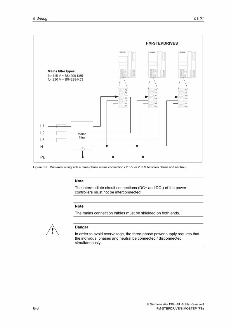
Figure 6-7 Multi-axis wiring with a three-phase mains connection (115 V or 230 V between phase and neutral)
NoteThe intermediate circuit connections (DC+ and DC-) of the powercontrollers must not be interconnected!
NoteThe mains connection cables must be shielded on both ends.
! DangerIn order to avoid overvoltage, the three-phase power supply requires thatthe individual phases and neutral be connected / disconnectedsimultaneously.
01.01 6 Wiring
© Siemens AG 1998 All Rights Reserved FM-STEPDRIVE/SIMOSTEP (FB) 6-9
FM-STEPDRIVES
DC+
DC-
115
230
N
PE
MS
DC+
DC-
115
230
N
PE
MS
DC+
DC-
115
230
N
PE
MS
Mainsfilter
L1
L2
L3
PE
Main filter types:
for 230 V = B84143-B8-R
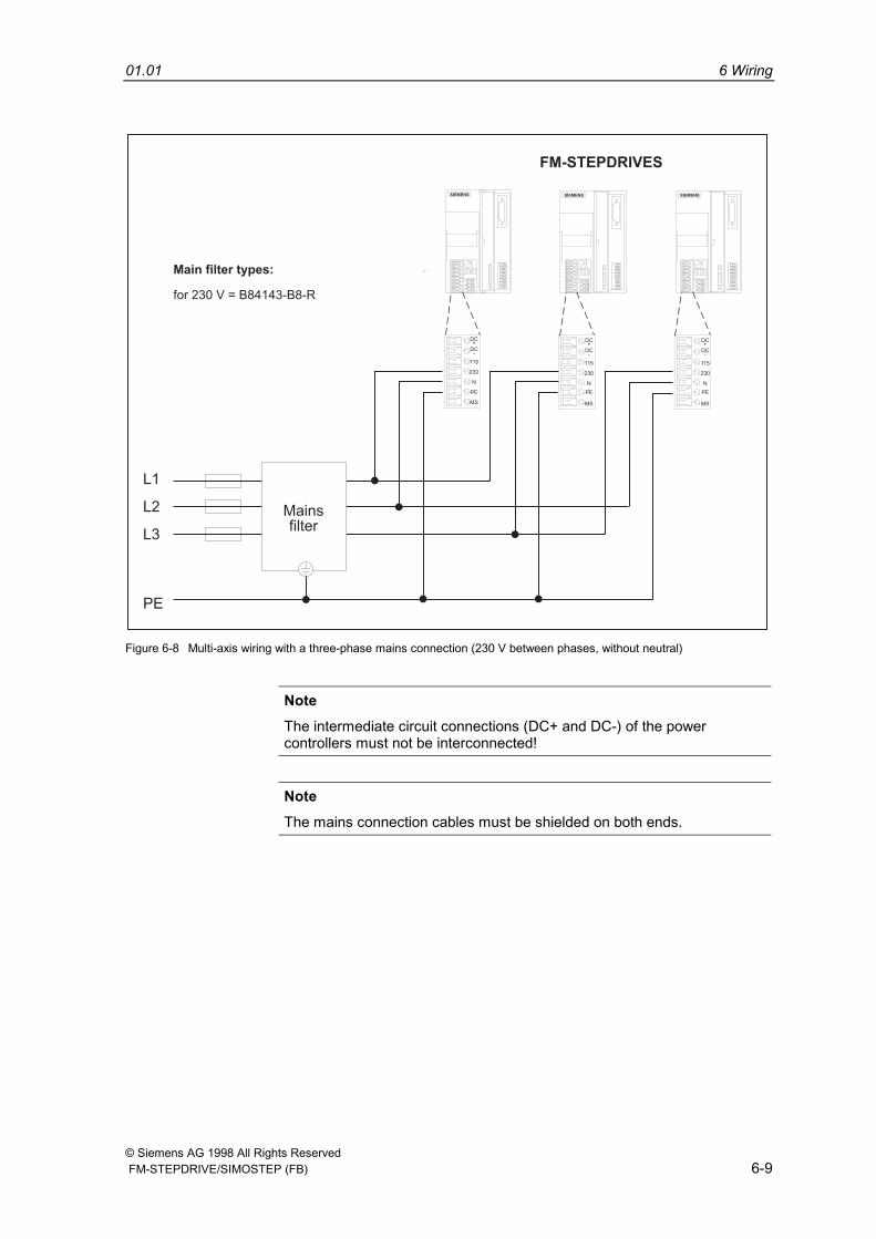
Figure 6-8 Multi-axis wiring with a three-phase mains connection (230 V between phases, without neutral)
NoteThe intermediate circuit connections (DC+ and DC-) of the powercontrollers must not be interconnected!
NoteThe mains connection cables must be shielded on both ends.
6 Wiring 01.01
© Siemens AG 1998 All Rights Reserved6-10 FM-STEPDRIVE/SIMOSTEP (FB)
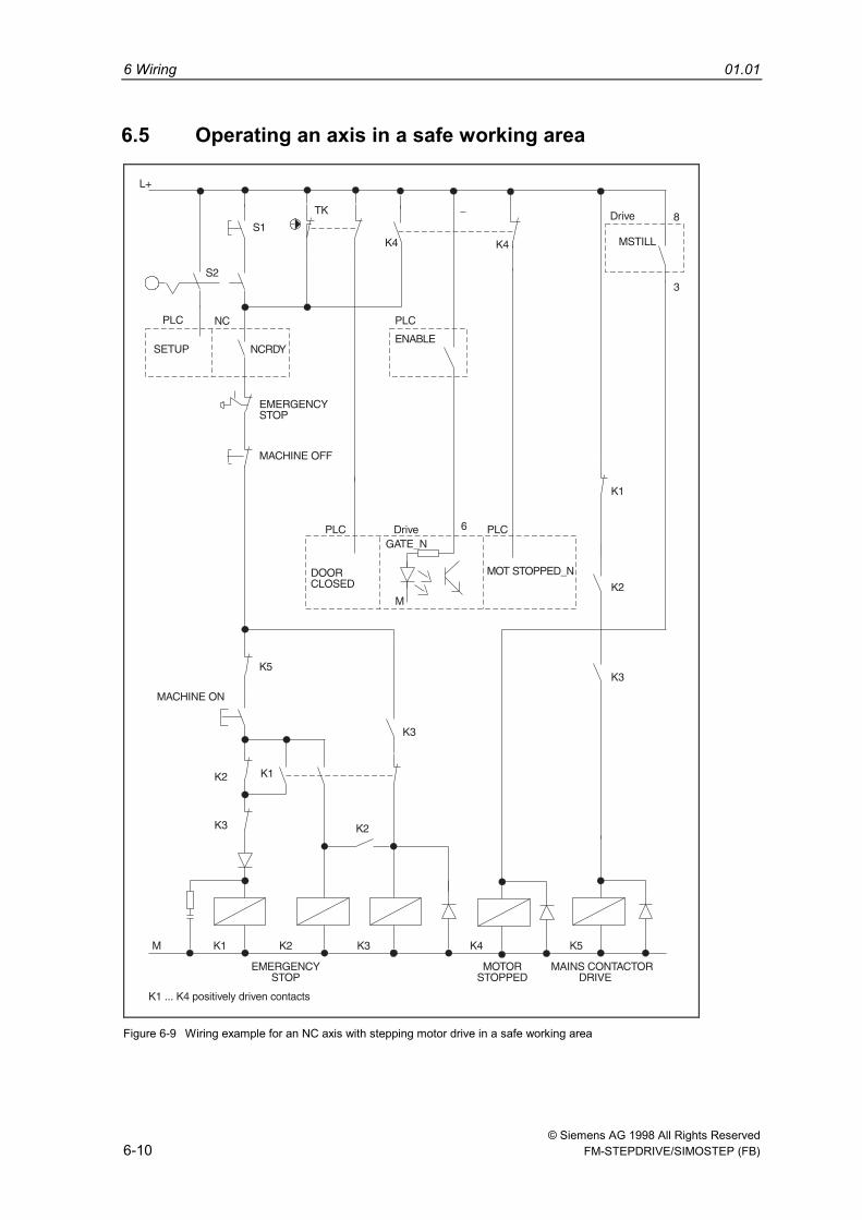
6.5 Operating an axis in a safe working area
Figure 6-9 Wiring example for an NC axis with stepping motor drive in a safe working area
01.01 6 Wiring
© Siemens AG 1998 All Rights Reserved FM-STEPDRIVE/SIMOSTEP (FB) 6-11
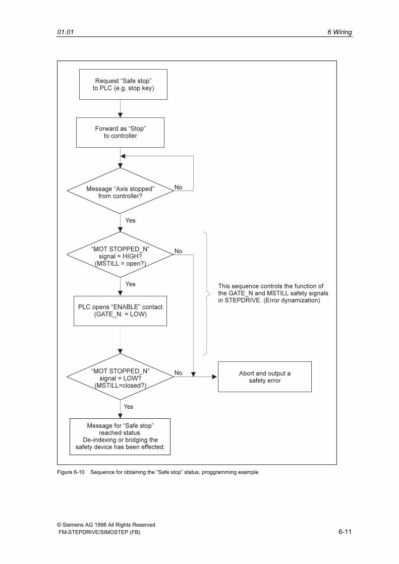
Figure 6-10 Sequence for obtaining the “Safe stop” status, proggramming example
6 Wiring 01.01
© Siemens AG 1998 All Rights Reserved6-12 FM-STEPDRIVE/SIMOSTEP (FB)
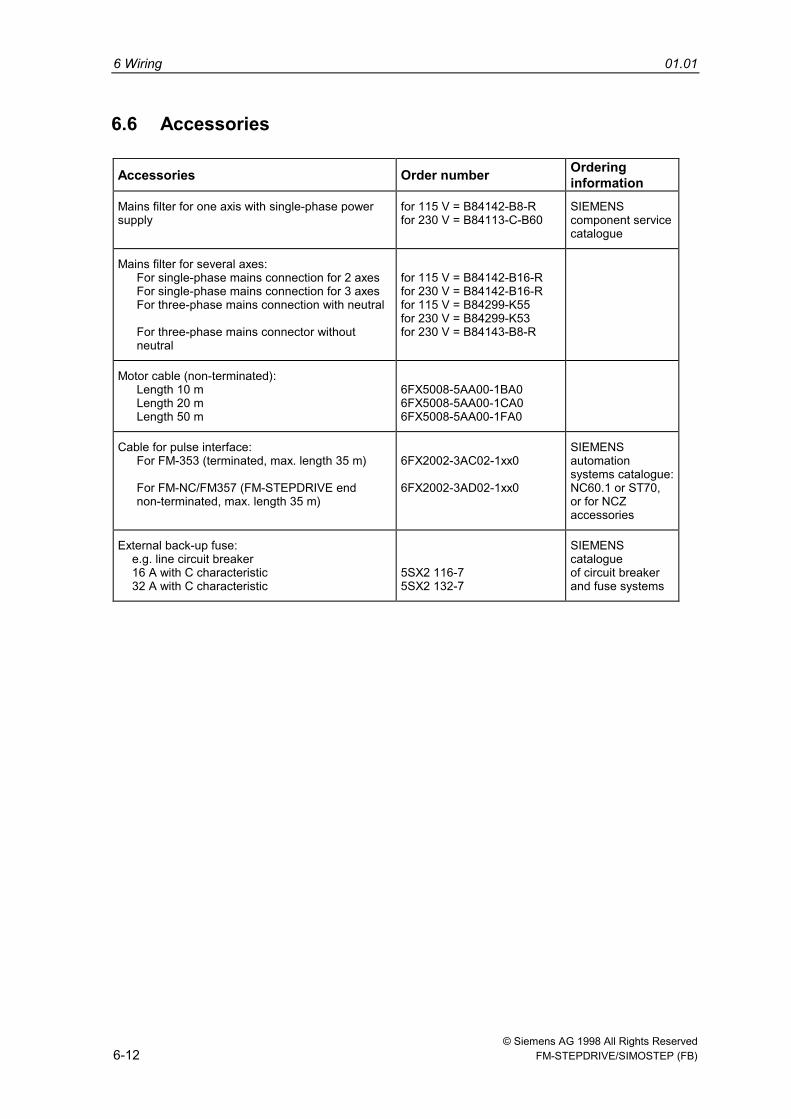
6.6 Accessories
Accessories Order number Orderinginformation
Mains filter for one axis with single-phase powersupply
for 115 V = B84142-B8-Rfor 230 V = B84113-C-B60
SIEMENScomponent servicecatalogue
Mains filter for several axes:For single-phase mains connection for 2 axesFor single-phase mains connection for 3 axesFor three-phase mains connection with neutral
For three-phase mains connector withoutneutral
for 115 V = B84142-B16-Rfor 230 V = B84142-B16-Rfor 115 V = B84299-K55for 230 V = B84299-K53for 230 V = B84143-B8-R
Motor cable (non-terminated):Length 10 mLength 20 mLength 50 m
6FX5008-5AA00-1BA06FX5008-5AA00-1CA06FX5008-5AA00-1FA0
Cable for pulse interface:For FM-353 (terminated, max. length 35 m)
For FM-NC/FM357 (FM-STEPDRIVE endnon-terminated, max. length 35 m)
6FX2002-3AC02-1xx0
6FX2002-3AD02-1xx0
SIEMENSautomationsystems catalogue:NC60.1 or ST70,or for NCZaccessories
External back-up fuse:e.g. line circuit breaker16 A with C characteristic32 A with C characteristic
5SX2 116-75SX2 132-7
SIEMENScatalogueof circuit breakerand fuse systems

© Siemens AG 1998 All Rights Reserved FM-STEPDRIVE/SIMOSTEP (FB) 7-1
Setup 7
7 Setup 01.01
© Siemens AG 1998 All Rights Reserved7-2 FM-STEPDRIVE/SIMOSTEP (FB)
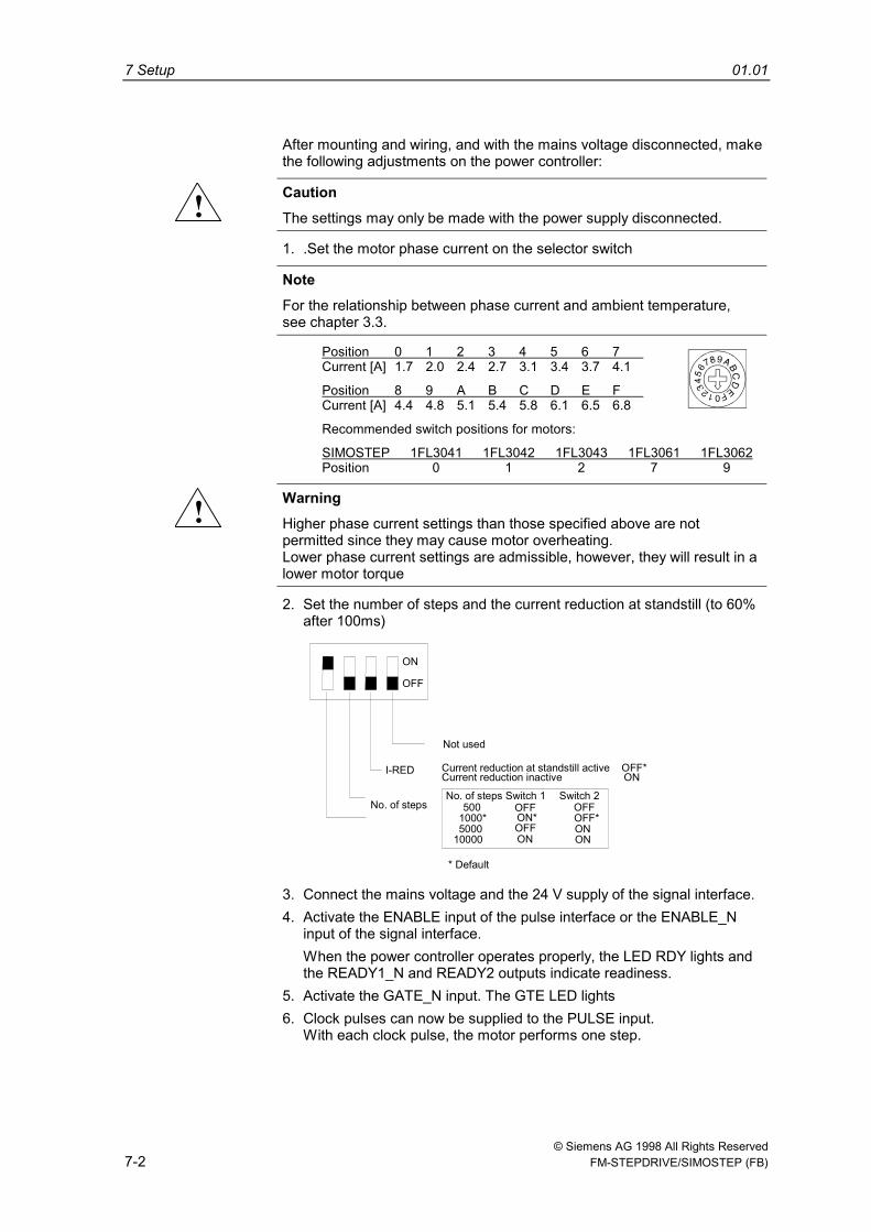
After mounting and wiring, and with the mains voltage disconnected, makethe following adjustments on the power controller:
! CautionThe settings may only be made with the power supply disconnected.
1. .Set the motor phase current on the selector switch
NoteFor the relationship between phase current and ambient temperature,see chapter 3.3.
Position 0 1 2 3 4 5 6 7 Current [A] 1.7 2.0 2.4 2.7 3.1 3.4 3.7 4.1
Position 8 9 A B C D E F Current [A] 4.4 4.8 5.1 5.4 5.8 6.1 6.5 6.8
Recommended switch positions for motors:
SIMOSTEP 1FL3041 1FL3042 1FL3043 1FL3061 1FL3062Position 0 1 2 7 9
! WarningHigher phase current settings than those specified above are notpermitted since they may cause motor overheating.Lower phase current settings are admissible, however, they will result in alower motor torque
2. Set the number of steps and the current reduction at standstill (to 60%after 100ms)
I-RED Current reduction at standstill active OFF*Current reduction inactive ON
ON
No. of steps
Not used
No. of steps Switch 1 Switch 2500
1000*5000
10000ONOFF*
ON
OFFON*
ON
OFF
OFF
* Default
OFF
3. Connect the mains voltage and the 24 V supply of the signal interface.4. Activate the ENABLE input of the pulse interface or the ENABLE_N
input of the signal interface.When the power controller operates properly, the LED RDY lights andthe READY1_N and READY2 outputs indicate readiness.
5. Activate the GATE_N input. The GTE LED lights6. Clock pulses can now be supplied to the PULSE input.
With each clock pulse, the motor performs one step.

© Siemens AG 1998 All Rights Reserved FM-STEPDRIVE/SIMOSTEP (FB) 8-1
Status indicators and troubleshooting 8
8 Status indicators and troubleshooting 01.01
© Siemens AG 1998 All Rights Reserved8-2 FM-STEPDRIVE/SIMOSTEP (FB)
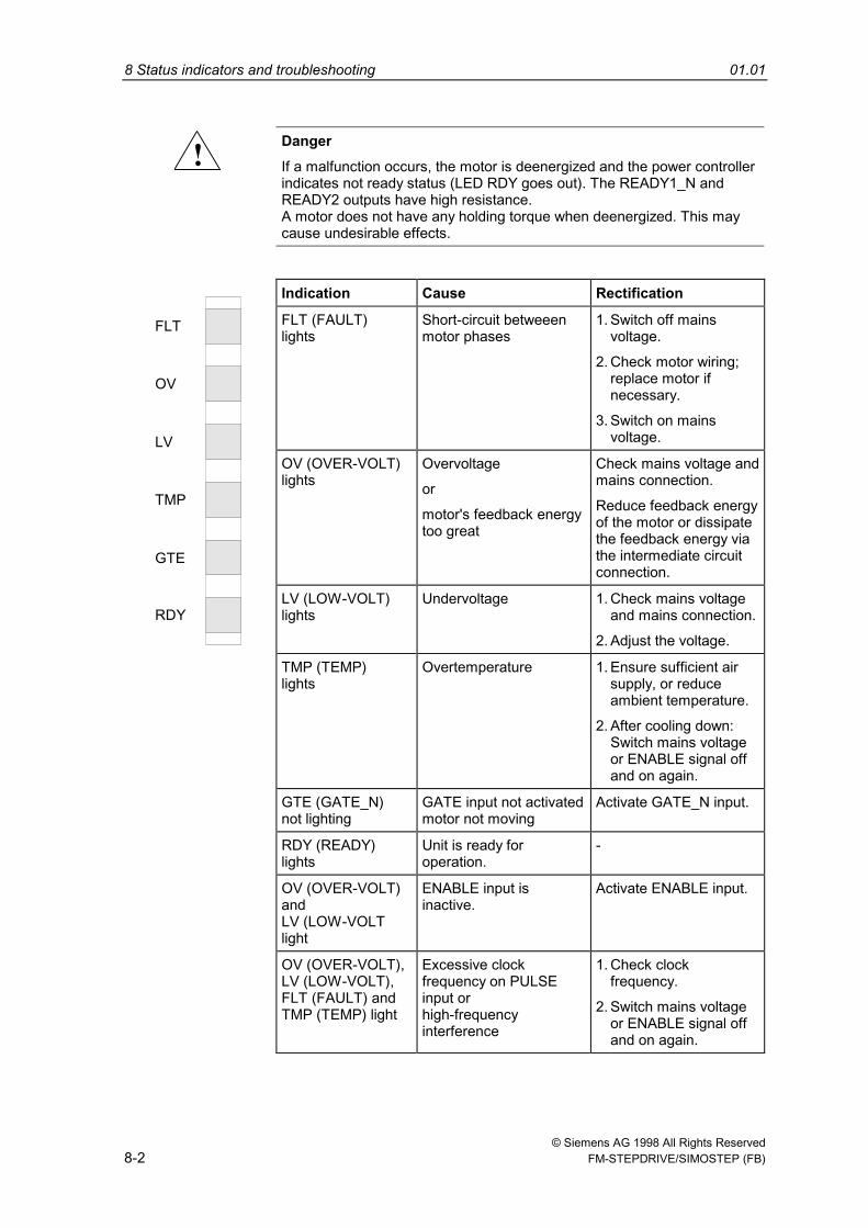
! DangerIf a malfunction occurs, the motor is deenergized and the power controllerindicates not ready status (LED RDY goes out). The READY1_N andREADY2 outputs have high resistance.A motor does not have any holding torque when deenergized. This maycause undesirable effects.
Indication Cause Rectification
FLT (FAULT)lights
Short-circuit betweeenmotor phases
1. Switch off mainsvoltage.
2. Check motor wiring;replace motor ifnecessary.
3. Switch on mainsvoltage.
OV (OVER-VOLT)lights
Overvoltage
or
motor's feedback energytoo great
Check mains voltage andmains connection.
Reduce feedback energyof the motor or dissipatethe feedback energy viathe intermediate circuitconnection.
LV (LOW-VOLT)lights
Undervoltage 1. Check mains voltageand mains connection.
2. Adjust the voltage.
TMP (TEMP)lights
Overtemperature 1. Ensure sufficient airsupply, or reduceambient temperature.
2. After cooling down:Switch mains voltageor ENABLE signal offand on again.
GTE (GATE_N)not lighting
GATE input not activatedmotor not moving
Activate GATE_N input.
RDY (READY)lights
Unit is ready foroperation.
-
OV (OVER-VOLT)andLV (LOW-VOLTlight
ENABLE input isinactive.
Activate ENABLE input.
FLT
OV
LV
TMP
RDY
GTE
OV (OVER-VOLT),LV (LOW-VOLT),FLT (FAULT) andTMP (TEMP) light
Excessive clockfrequency on PULSEinput orhigh-frequencyinterference
1. Check clockfrequency.
2. Switch mains voltageor ENABLE signal offand on again.
01.01 8 Status indicators and troubleshooting
© Siemens AG 1998 All Rights Reserved FM-STEPDRIVE/SIMOSTEP (FB) 8-3
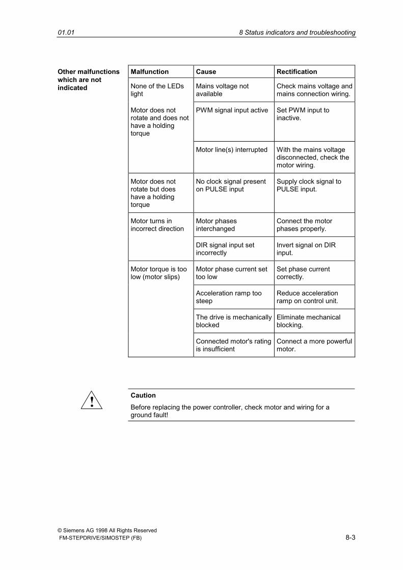
Malfunction Cause Rectification
None of the LEDslight
Mains voltage notavailable
Check mains voltage andmains connection wiring.
Motor does notrotate and does nothave a holdingtorque
PWM signal input active Set PWM input toinactive.
Motor line(s) interrupted With the mains voltagedisconnected, check themotor wiring.
Motor does notrotate but doeshave a holdingtorque
No clock signal presenton PULSE input
Supply clock signal toPULSE input.
Motor turns inincorrect direction
Motor phasesinterchanged
Connect the motorphases properly.
DIR signal input setincorrectly
Invert signal on DIRinput.
Motor torque is toolow (motor slips)
Motor phase current settoo low
Set phase currentcorrectly.
Acceleration ramp toosteep
Reduce accelerationramp on control unit.
The drive is mechanicallyblocked
Eliminate mechanicalblocking.
Other malfunctionswhich are notindicated
Connected motor's ratingis insufficient
Connect a more powerfulmotor.
! CautionBefore replacing the power controller, check motor and wiring for aground fault!
8 Status indicators and troubleshooting 01.01
© Siemens AG 1998 All Rights Reserved8-4 FM-STEPDRIVE/SIMOSTEP (FB)

© Siemens AG 1998 All Rights Reserved FM-STEPDRIVE/SIMOSTEP (FB) 9-1
SIMOSTEP specifications 9
9 SIMOSTEP specifications 01.01
© Siemens AG 1998 All Rights Reserved9-2 FM-STEPDRIVE/SIMOSTEP (FB)
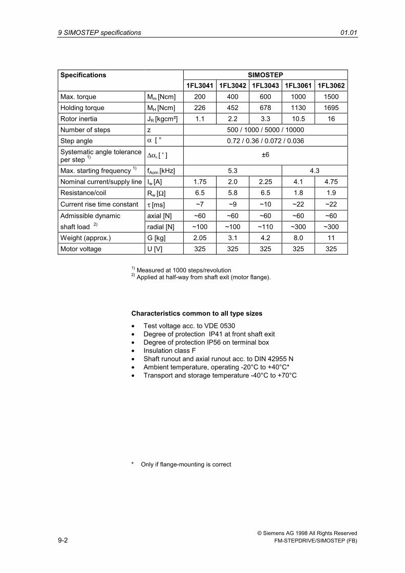
Specifications SIMOSTEP1FL3041 1FL3042 1FL3043 1FL3061 1FL3062
Max. torque Mm [Ncm] 200 400 600 1000 1500Holding torque MH [Ncm] 226 452 678 1130 1695Rotor inertia JR [kgcm²] 1.1 2.2 3.3 10.5 16Number of steps z 500 / 1000 / 5000 / 10000Step angle α= [ ° 0.72 / 0.36 / 0.072 / 0.036Systematic angle toleranceper step 1) ∆αs [ ' ] ±6
Max. starting frequency 1) fAom [kHz] 5.3 4.3Nominal current/supply line Iw [A] 1.75 2.0 2.25 4.1 4.75Resistance/coil Rw [Ω] 6.5 5.8 6.5 1.8 1.9Current rise time constant τ=[ms] ~7 ~9 ~10 ~22 ~22Admissible dynamic axial [N] ~60 ~60 ~60 ~60 ~60shaft load 2) radial [N] ~100 ~100 ~110 ~300 ~300Weight (approx.) G [kg] 2.05 3.1 4.2 8.0 11Motor voltage U [V] 325 325 325 325 325
1) Measured at 1000 steps/revolution2) Applied at half-way from shaft exit (motor flange).
Characteristics common to all type sizes
• Test voltage acc. to VDE 0530• Degree of protection IP41 at front shaft exit• Degree of protection IP56 on terminal box• Insulation class F• Shaft runout and axial runout acc. to DIN 42955 N• Ambient temperature, operating -20°C to +40°C*• Transport and storage temperature -40°C to +70°C
* Only if flange-mounting is correct
01.01 9 SIMOSTEP specifications
© Siemens AG 1998 All Rights Reserved FM-STEPDRIVE/SIMOSTEP (FB) 9-3
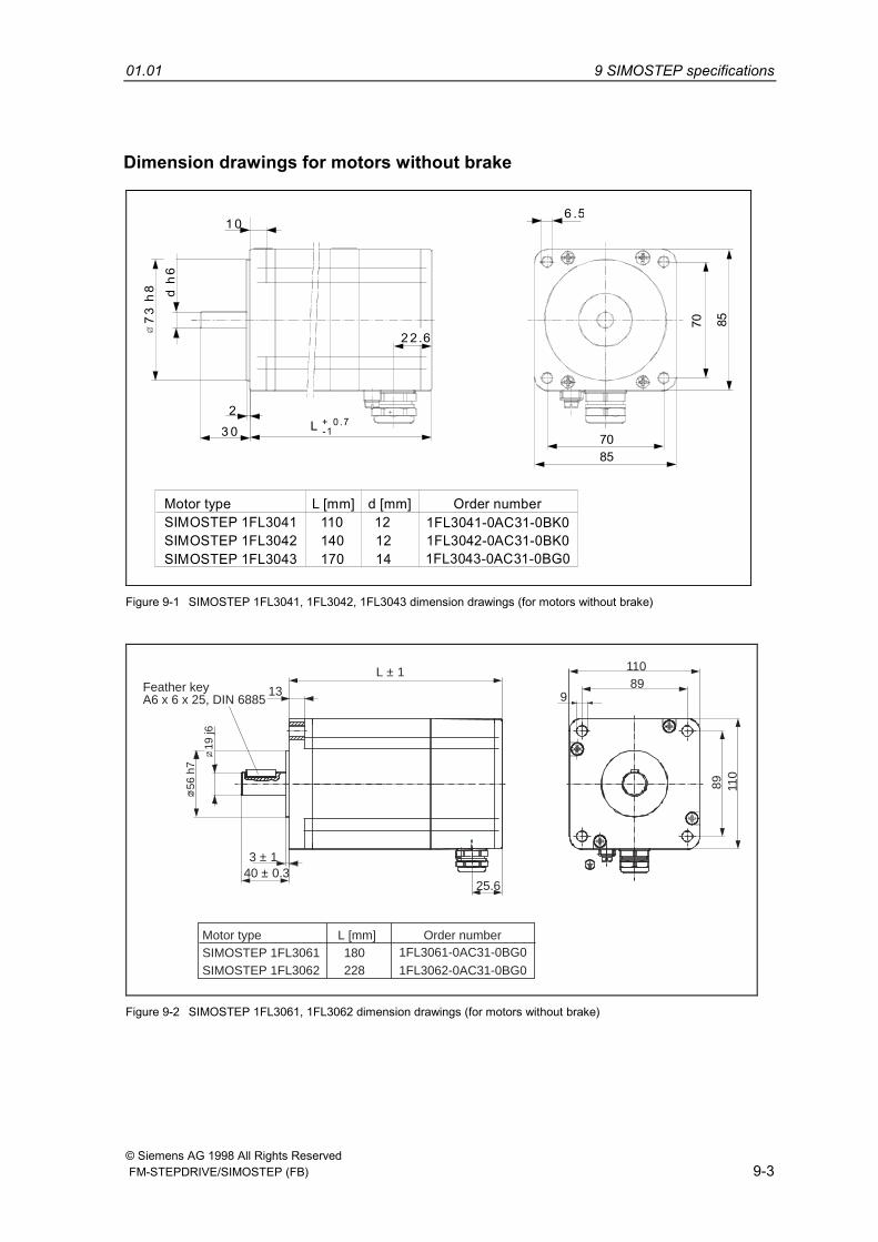
Dimension drawings for motors without brake
3 0
d h
6
L7085
2 2 .6
6 .51 0
73
h8
2-1+ 0 .7
70 85
Motor typeSIMOSTEP 1FL3041 110 12SIMOSTEP 1FL3042 140 12SIMOSTEP 1FL3043 170 14
d [mm] Order number1FL3041-0AC31-0BK01FL3042-0AC31-0BK01FL3043-0AC31-0BG0
L [mm]
Figure 9-1 SIMOSTEP 1FL3041, 1FL3042, 1FL3043 dimension drawings (for motors without brake)
Order number1FL3061-0AC31-0BG0
1FL3062-0AC31-0BG0
Feather keyA6 x 6 x 25, DIN 6885
19 j6
40 ± 0.3
L ± 1
13
56 h
7
3 ± 1
25.6
9
11089
89 110
Motor type L [mm] SIMOSTEP 1FL3061 180 SIMOSTEP 1FL3062 228
Figure 9-2 SIMOSTEP 1FL3061, 1FL3062 dimension drawings (for motors without brake)
9 SIMOSTEP specifications 01.01
© Siemens AG 1998 All Rights Reserved9-4 FM-STEPDRIVE/SIMOSTEP (FB)
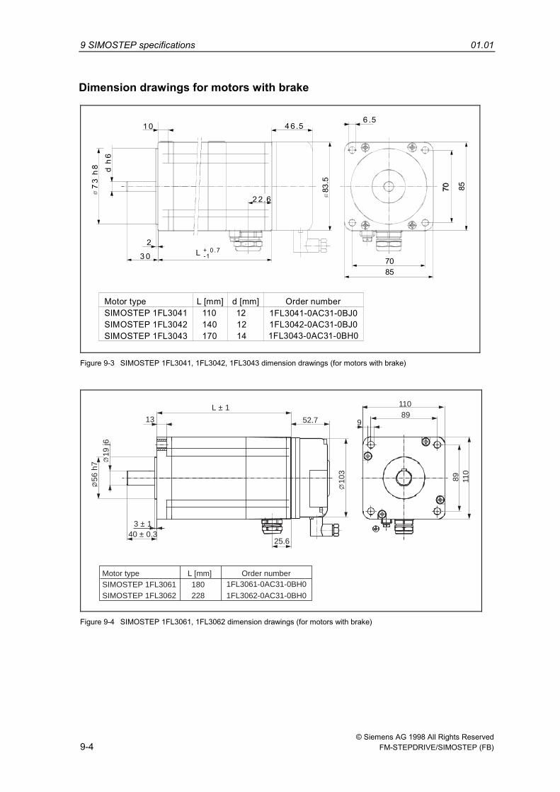
Dimension drawings for motors with braked
h6
L3 0
4 6.5
2 2.6
1 0
73
h8
2-1+ 0 .7
7085
6 .5
83.5
85
Motor typeSIMOSTEP 1FL3041 110 12SIMOSTEP 1FL3042 140 12SIMOSTEP 1FL3043 170 14
d [mm] Order number1FL3041-0AC31-0BJ01FL3042-0AC31-0BJ01FL3043-0AC31-0BH0
L [mm]
Figure 9-3 SIMOSTEP 1FL3041, 1FL3042, 1FL3043 dimension drawings (for motors with brake)
52.7
103
Order number1FL3061-0AC31-0BH0
1FL3062-0AC31-0BH0
19 j6
40 ± 0.3
L ± 1
13
56 h
7
3 ± 1
25.6
9
11089
89 110
Motor type L [mm] SIMOSTEP 1FL3061 180 SIMOSTEP 1FL3062 228
Figure 9-4 SIMOSTEP 1FL3061, 1FL3062 dimension drawings (for motors with brake)
01.01 9 SIMOSTEP specifications
© Siemens AG 1998 All Rights Reserved FM-STEPDRIVE/SIMOSTEP (FB) 9-5
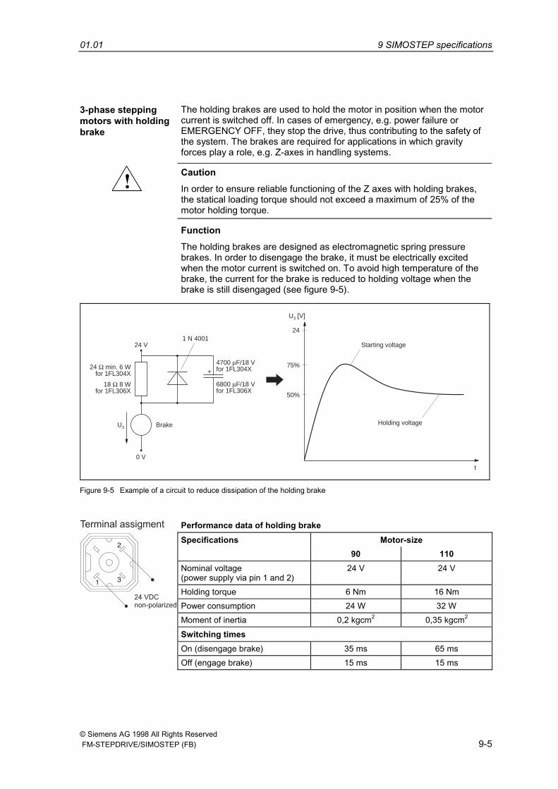
3-phase steppingmotors with holdingbrake
The holding brakes are used to hold the motor in position when the motorcurrent is switched off. In cases of emergency, e.g. power failure orEMERGENCY OFF, they stop the drive, thus contributing to the safety ofthe system. The brakes are required for applications in which gravityforces play a role, e.g. Z-axes in handling systems.
! CautionIn order to ensure reliable functioning of the Z axes with holding brakes,the statical loading torque should not exceed a maximum of 25% of themotor holding torque.
FunctionThe holding brakes are designed as electromagnetic spring pressurebrakes. In order to disengage the brake, it must be electrically excitedwhen the motor current is switched on. To avoid high temperature of thebrake, the current for the brake is reduced to holding voltage when thebrake is still disengaged (see figure 9-5).
4700 µF/18 Vfor 1FL304X
U3 [V]
Starting voltage
Holding voltage
t
24
75%
50%
24 V
Brake
0 V
U3
+
1 N 4001
6800 µF/18 Vfor 1FL306X
24 Ω min. 6 Wfor 1FL304X
18 Ω 8 Wfor 1FL306X
Figure 9-5 Example of a circuit to reduce dissipation of the holding brake
Performance data of holding brakeSpecifications Motor-size
90 110Nominal voltage(power supply via pin 1 and 2)
24 V 24 V
Holding torque 6 Nm 16 NmPower consumption 24 W 32 WMoment of inertia 0,2 kgcm2 0,35 kgcm2
Switching timesOn (disengage brake) 35 ms 65 ms
13
2
24 VDCnon-polarized
Terminal assigment
Off (engage brake) 15 ms 15 ms
9 SIMOSTEP specifications 01.01
© Siemens AG 1998 All Rights Reserved9-6 FM-STEPDRIVE/SIMOSTEP (FB)
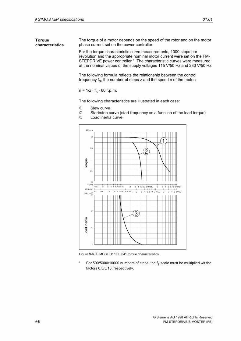
Torquecharacteristics
The torque of a motor depends on the speed of the rotor and on the motorphase current set on the power controller.
For the torque characteristic curve measurements, 1000 steps perrevolution and the appropriate nominal motor current were set on the FM-STEPDRIVE power controller *. The characteristic curves were measuredat the nominal values of the supply voltages 115 V/50 Hz and 230 V/50 Hz.
The following formula reflects the relationship between the controlfrequency fs, the number of steps z and the speed n of the motor:
n = 1/z · fs · 60 r.p.m.
The following characteristics are illustrated in each case:
Slew curve Start/stop curve (start frequency as a function of the load torque) Load inertia curve
Figure 9-6 SIMOSTEP 1FL3041 torque characteristics
* For 500/5000/10000 numbers of steps, the fs scale must be multiplied wit thefactors 0.5/5/10, respectively.
01.01 9 SIMOSTEP specifications
© Siemens AG 1998 All Rights Reserved FM-STEPDRIVE/SIMOSTEP (FB) 9-7
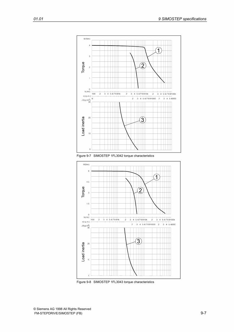
Figure 9-7 SIMOSTEP 1FL3042 torque characteristics
Figure 9-8 SIMOSTEP 1FL3043 torque characteristics
9 SIMOSTEP specifications 01.01
© Siemens AG 1998 All Rights Reserved9-8 FM-STEPDRIVE/SIMOSTEP (FB)
Torq
ueL
oad
iner
tia
1
2
3
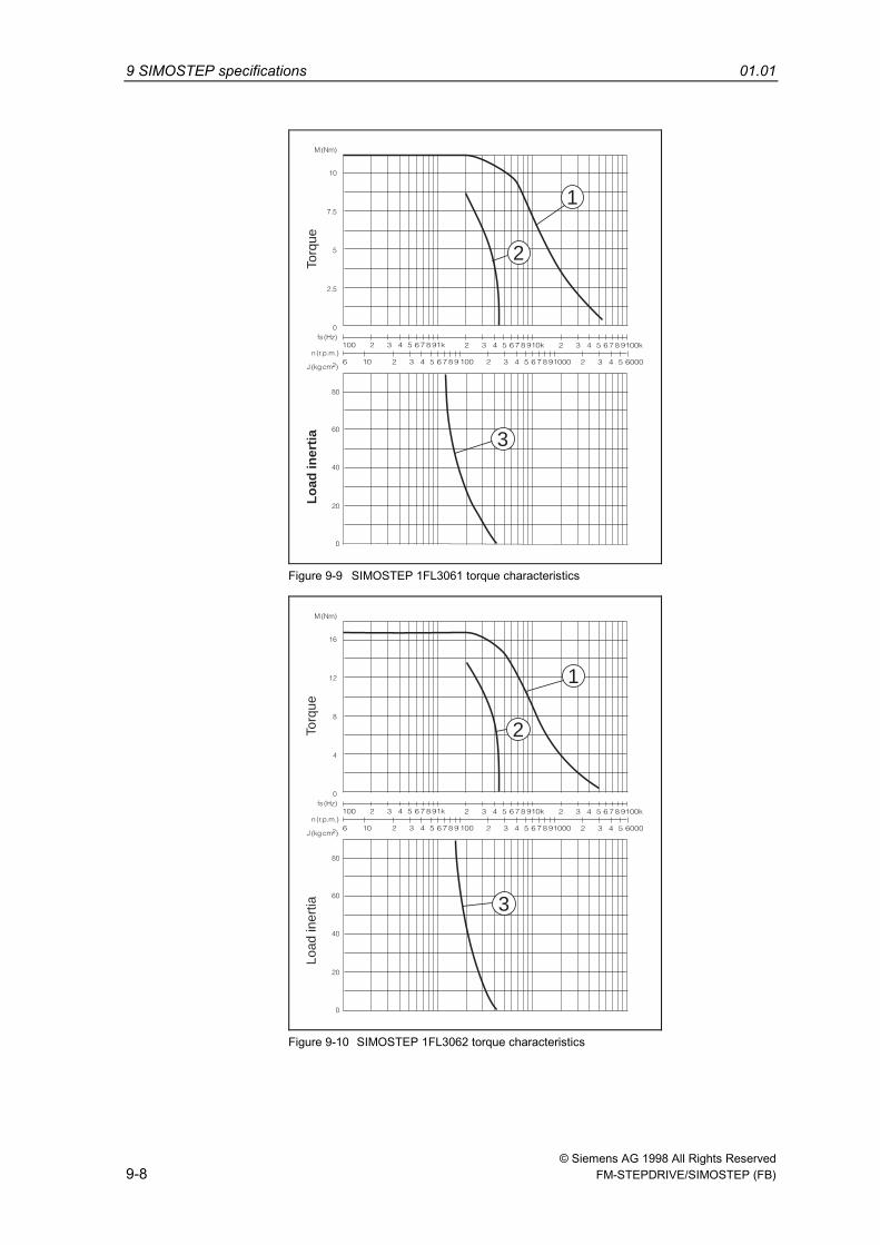
Figure 9-9 SIMOSTEP 1FL3061 torque characteristics
Torq
ueLo
ad in
ertia
1
2
3
Figure 9-10 SIMOSTEP 1FL3062 torque characteristics
© Siemens AG 1998 All Rights Reserved FM-STEPDRIVE/SIMOSTEP (FB) 10-1
Stepping motor parameters andcharacteristics
10.1 Basic concepts ........................................................................ 10-2
10.2 Torque characteristics............................................................. 10-3
10
10 Stepping motor parameters and characteristics 01.01
© Siemens AG 1998 All Rights Reserved10-2 FM-STEPDRIVE/SIMOSTEP (FB)
A number of certain parameters and characteristics must be known forexamining and selecting a stepping motor. Each stepping motor has itsspecific properties in conjunction with the power controller used; theseproperties are represented by characteristic curves. To facilitate anunderstanding of their contents and meaning, the essential parametersand the usage of the characteristics are explained here.
10.1 Basic concepts
Step angle A step refers to a motor shaft rotation by the step angle ; the step isinitiated by a control pulse.
Number of steps The number of steps specifies the number of steps the rotor performs perrevolution. The number of steps can be adjusted for a 3-phase steppingmotor.
Holding torque The rotor is held in each step position due to the DC excitation of the coilsunless its holding torque MH is exceeded on the motor shaft.
Systematic angletolerance
The systematic angle tolerance per step ∆αs specifies the maximumnumber of angular minutes a step may deviate from the nominal stepangle.
Control and steppingfrequency
With a continuous sequence of control pulses at a control frequency fS,the motor shaft will also execute a sequence of steps at the (same)stepping frequency fZ.
Speed From a specific control frequency onwards (depending on motor type andmechanical load) the step-by-step movement of the motor shaft vergesinto a continuous rotary movement. The following then applies fro thespeed n of the motor:
n = α/360° · fZ · 60 r.p.m. (fz[Hz])
Torques If the rotating motor shaft is subjected to a load torque ML, the motor willcontinue to follow the control frequeny synchronously unless the loadtorque exceeds a certain limit, i.e. the maximum torque at maximum slewstepping rate MBm.
In this case, the rotor cannot follow the control frequency any more, and astep “loss” will occur, where control frequency and stepping frequency areno longer identical.
Such a situation can be avoided by selecting the correct motor and bycontrolling it correctly
11.98 10 Stepping motor parameters and characteristics
© Siemens AG 1998 All Rights Reserved FM-STEPDRIVE/SIMOSTEP (FB) 10-3
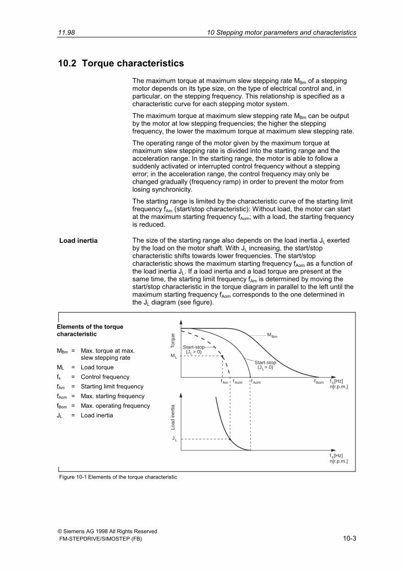
10.2 Torque characteristicsThe maximum torque at maximum slew stepping rate MBm of a steppingmotor depends on its type size, on the type of electrical control and, inparticular, on the stepping frequency. This relationship is specified as acharacteristic curve for each stepping motor system.
The maximum torque at maximum slew stepping rate MBm can be outputby the motor at low stepping frequencies; the higher the steppingfrequency, the lower the maximum torque at maximum slew stepping rate.
The operating range of the motor given by the maximum torque atmaximum slew stepping rate is divided into the starting range and theacceleration range. In the starting range, the motor is able to follow asuddenly activated or interrupted control frequency without a steppingerror; in the acceleration range, the control frequency may only bechanged gradually (frequency ramp) in order to prevent the motor fromlosing synchronicity.
The starting range is limited by the characteristic curve of the starting limitfrequency fAm (start/stop characteristic): Without load, the motor can startat the maximum starting frequency fAom; with a load, the starting frequencyis reduced.
Load inertia The size of the starting range also depends on the load inertia JL exertedby the load on the motor shaft. With JL increasing, the start/stopcharacteristic shifts towards lower frequencies. The start/stopcharacteristic shows the maximum starting frequency fAom as a function ofthe load inertia JL. If a load inertia and a load torque are present at thesame time, the starting limit frequency fAm is determined by moving thestart/stop characteristic in the torque diagram in parallel to the left until themaximum starting frequency fAom corresponds to the one determined inthe JL diagram (see figure).
Start-stop(J > 0)L
MBm
Start-stop(J = 0)L
fAm fAom fBomfAom f [Hz]n[r.p.m.]s
f [Hz]n[r.p.m.]s
ML
JL
Torq
ueLo
ad in
ertia
Figure 10-1 Elements of the torque characteristic
Elements of the torquecharacteristic
MBm = Max. torque at max.slew stepping rate
ML = Load torquefs = Control frequencyfAm = Starting limit frequencyfAom = Max. starting frequencyfBom = Max. operating frequencyJL = Load inertia

10 Stepping motor parameters and characteristics 01.01
© Siemens AG 1998 All Rights Reserved10-4 FM-STEPDRIVE/SIMOSTEP (FB)
Siemens AGSuggestions
Corrections
A&D MC BMSP.O. Box 31 80
For Publication/Manual:
SIMATIC
D-91050 ErlangenFederal Republic of Germany
FM-STEPDRIVE/SIMOSTEP
Power Controller and 3-Phase SteppingMotors
Supplier Documentation
From:
Name:
Functional description
Order No.: 6SN1197-0AA70-0YP4Edition: 01.01
Address of your company/department
Street etc.:
ZIP: _____________ City:
Phone: ___________ /
Fax: _____________ /
Should you come across any printing errorswhen reading this publication, please notifyus on this sheet. Suggestions forimprovement are also welcome.

Siemens AGAutomation and DrivesMotion Control Systems
Postfach 3180, D - 91050 ErlangenFederal Republic of Germany
© Siemens AG 1998Subject to change without prior notice
Siemens Aktiengesellschaft Order No.: 6SN1197-0AA70-0YP4Printed in the Federal Republic of Germany570093200199 / PJ 12980.1