Embed Size (px)
Citation preview
V1.2 Sept 2014 Datasheet
Ag5200 Power-over-Ethernet Plus Module
© Silver Telecom 2014
Silvertel
1 Features
IEEE802.3at and IEEE802.3af compliant
Maximum 30W output power
Dual In-Line (DIL) package size – 50.6mm (L) x 30mm (W)
Overload, short-circuit and thermal
protection
Adjustable output voltage
Minimal (low cost) external components
Low output ripple & noise
High efficiency DC/DC converter
1500Vdc isolation (input to output)
Silvertel “design-in” assistance
2 Description
The Ag5200 Power-over-Ethernet (PoE) module is designed to extract power from a conventional twisted pair Category 5 Ethernet cable, conforming to the IEEE 802.3at PoE standard. The Ag5200 has been designed to extract power from Power Sourcing Equipment (PSE) over a conventional twisted pair Category 5 Ethernet cable. The modules input conform to the IEEE803.2at standard for signature recognition and class programming. The high efficiency DC/DC converter operates over a wide input voltage range with a low ripple and low noise output. The DC/DC converter also has built-in output overload, output short-circuit and over-temperature protection and provides a 1500Vdc (input to output) isolation barrier.
PbPb
V1.2 Sept 2014 Data Sheet Ag5200
Power-over-Ethernet Plus Module
© Silver Telecom 2014 2
Table of Contents 1 Features ....................................................................................................................... 1 2 Description .................................................................................................................... 1
Table of Contents ............................................................................................................. 2 Table of Figures ............................................................................................................... 2
3 Ag5200 Product Selector† ............................................................................................ 3 4 Pin Description ............................................................................................................. 4 5 Functional Description .................................................................................................. 5
5.1 Inputs ..................................................................................................................... 5
5.2 PD Signature ......................................................................................................... 5 5.3 Isolation ................................................................................................................. 6 5.4 Power Classification .............................................................................................. 6
5.5 AT Detection .......................................................................................................... 7 5.6 DC/DC Converter .................................................................................................. 8 5.7 Output Adjustment ................................................................................................. 8 5.8 Typical Connections .............................................................................................. 9
5.9 Output Power ....................................................................................................... 10 6 Typical Application ...................................................................................................... 10
7 Operating Temperature Range ................................................................................... 11 8 Protection ................................................................................................................... 12 9 EMC ............................................................................................................................ 12
10 Electrical Characteristics ......................................................................................... 12
10.1 Absolute Maximum Ratings*................................................................................ 12 10.2 Recommended Operating Conditions .................................................................. 12 10.3 DC Electrical Characteristics* .............................................................................. 13
11 Package .................................................................................................................. 14
Table of Figures
Figure 1: Block Diagram ...................................................................................................... 3
Figure 2: Ag5200 DIL Package Format................................................................................ 4 Figure 3: Typical System Diagram ....................................................................................... 5 Figure 4: Position of the Isolation Barrier ............................................................................. 6
Figure 5: Two Event Physical Layer Detect Configuration ................................................... 7 Figure 6: Output Adjustment ................................................................................................ 8
Figure 7: Typical PoE Only Connection Diagram ................................................................. 9 Figure 8: Typical Application .............................................................................................. 10
Figure 9: Ag5200 Operating Profile ................................................................................... 11
V1.2 Sept 2014 Data Sheet Ag5200
Power-over-Ethernet Plus Module
© Silver Telecom 2014 3
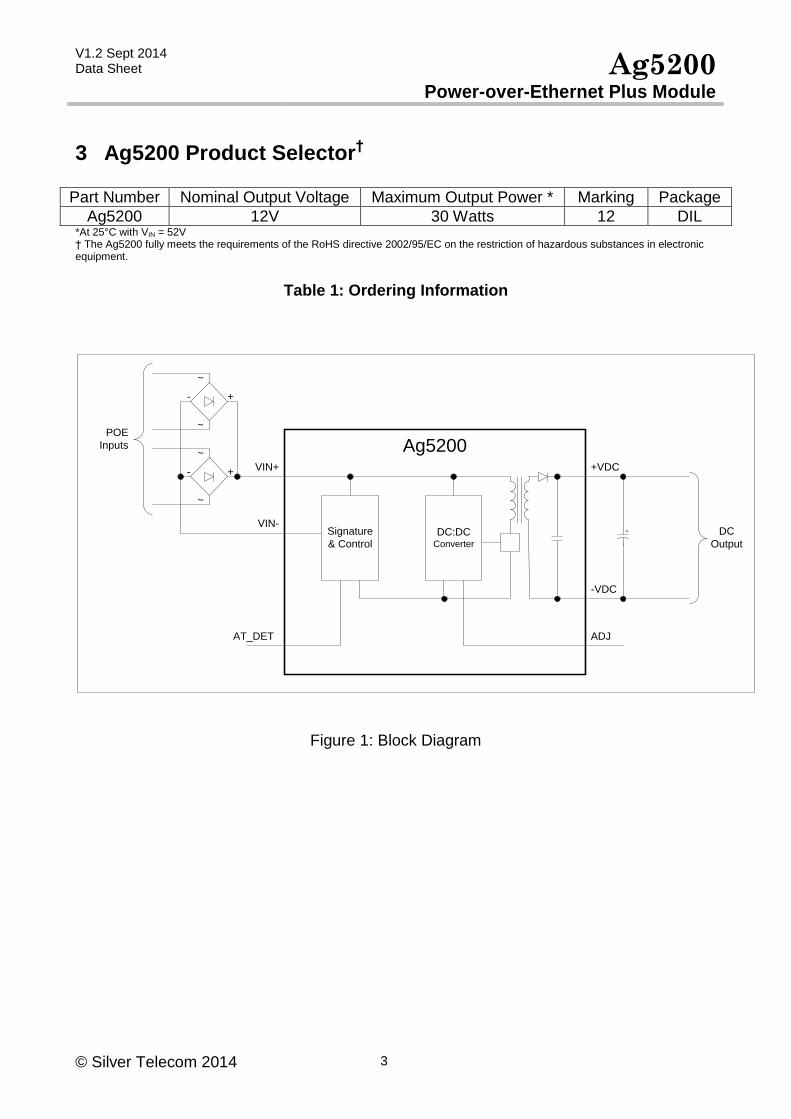
3 Ag5200 Product Selector†
Part Number Nominal Output Voltage Maximum Output Power * Marking Package
Ag5200 12V 30 Watts 12 DIL *At 25°C with VIN = 52V † The Ag5200 fully meets the requirements of the RoHS directive 2002/95/EC on the restriction of hazardous substances in electronic equipment.
Table 1: Ordering Information
Signature
& ControlDC:DC
Converter
Ag5200POE
Inputs
DC
Output
VIN+
VIN-
~
~
- +
~
~
- +
ADJ
-VDC
+VDC
+
AT_DET
Figure 1: Block Diagram
V1.2 Sept 2014 Data Sheet Ag5200
Power-over-Ethernet Plus Module
© Silver Telecom 2014 4
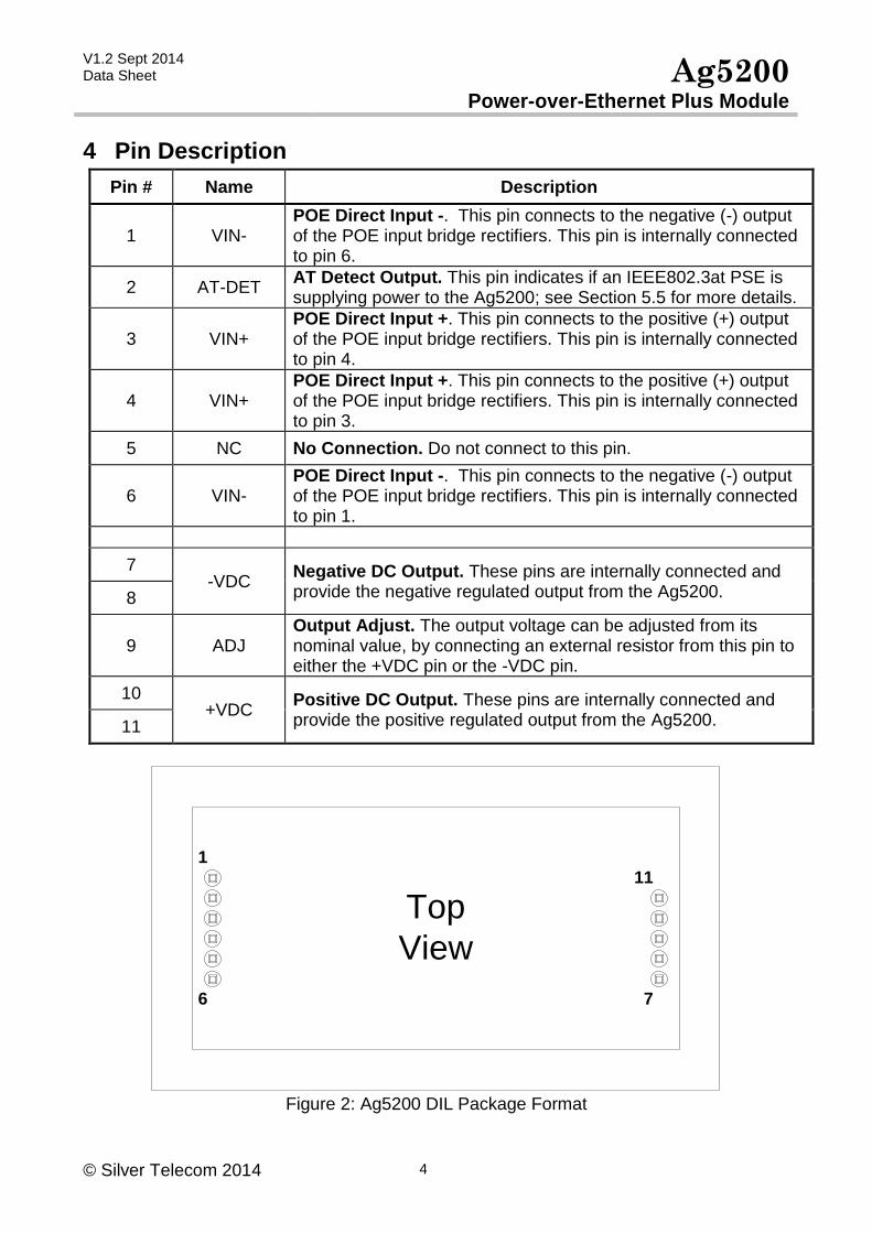
4 Pin Description
Pin # Name Description
1 VIN- POE Direct Input -. This pin connects to the negative (-) output of the POE input bridge rectifiers. This pin is internally connected to pin 6.
2 AT-DET AT Detect Output. This pin indicates if an IEEE802.3at PSE is supplying power to the Ag5200; see Section 5.5 for more details.
3 VIN+ POE Direct Input +. This pin connects to the positive (+) output of the POE input bridge rectifiers. This pin is internally connected to pin 4.
4 VIN+ POE Direct Input +. This pin connects to the positive (+) output of the POE input bridge rectifiers. This pin is internally connected to pin 3.
5 NC No Connection. Do not connect to this pin.
6 VIN- POE Direct Input -. This pin connects to the negative (-) output of the POE input bridge rectifiers. This pin is internally connected to pin 1.
7 -VDC
Negative DC Output. These pins are internally connected and provide the negative regulated output from the Ag5200. 8
9 ADJ Output Adjust. The output voltage can be adjusted from its nominal value, by connecting an external resistor from this pin to either the +VDC pin or the -VDC pin.
10 +VDC
Positive DC Output. These pins are internally connected and provide the positive regulated output from the Ag5200. 11
1
6
Top
View
7
11
Figure 2: Ag5200 DIL Package Format
V1.2 Sept 2014 Data Sheet Ag5200
Power-over-Ethernet Plus Module
© Silver Telecom 2014 5
5 Functional Description
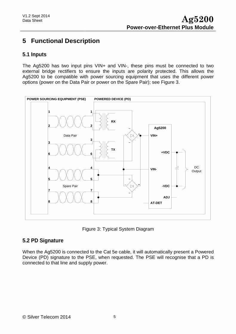
5.1 Inputs The Ag5200 has two input pins VIN+ and VIN-, these pins must be connected to two external bridge rectifiers to ensure the inputs are polarity protected. This allows the Ag5200 to be compatible with power sourcing equipment that uses the different power options (power on the Data Pair or power on the Spare Pair); see Figure 3.
Ag5200
VIN+
VIN-
POWERED DEVICE (PD)POWER SOURCING EQUIPMENT (PSE)
RX
TX
4
5
1
2
3
6
7
8
4
5
1
2
3
6
7
8
~
~
- +
~
~
- +Data Pair
Spare Pair
ADJ
-VDC
+VDC
AT-DET
DC
Output
+
Figure 3: Typical System Diagram
5.2 PD Signature When the Ag5200 is connected to the Cat 5e cable, it will automatically present a Powered Device (PD) signature to the PSE, when requested. The PSE will recognise that a PD is connected to that line and supply power.
V1.2 Sept 2014 Data Sheet Ag5200
Power-over-Ethernet Plus Module
© Silver Telecom 2014 6
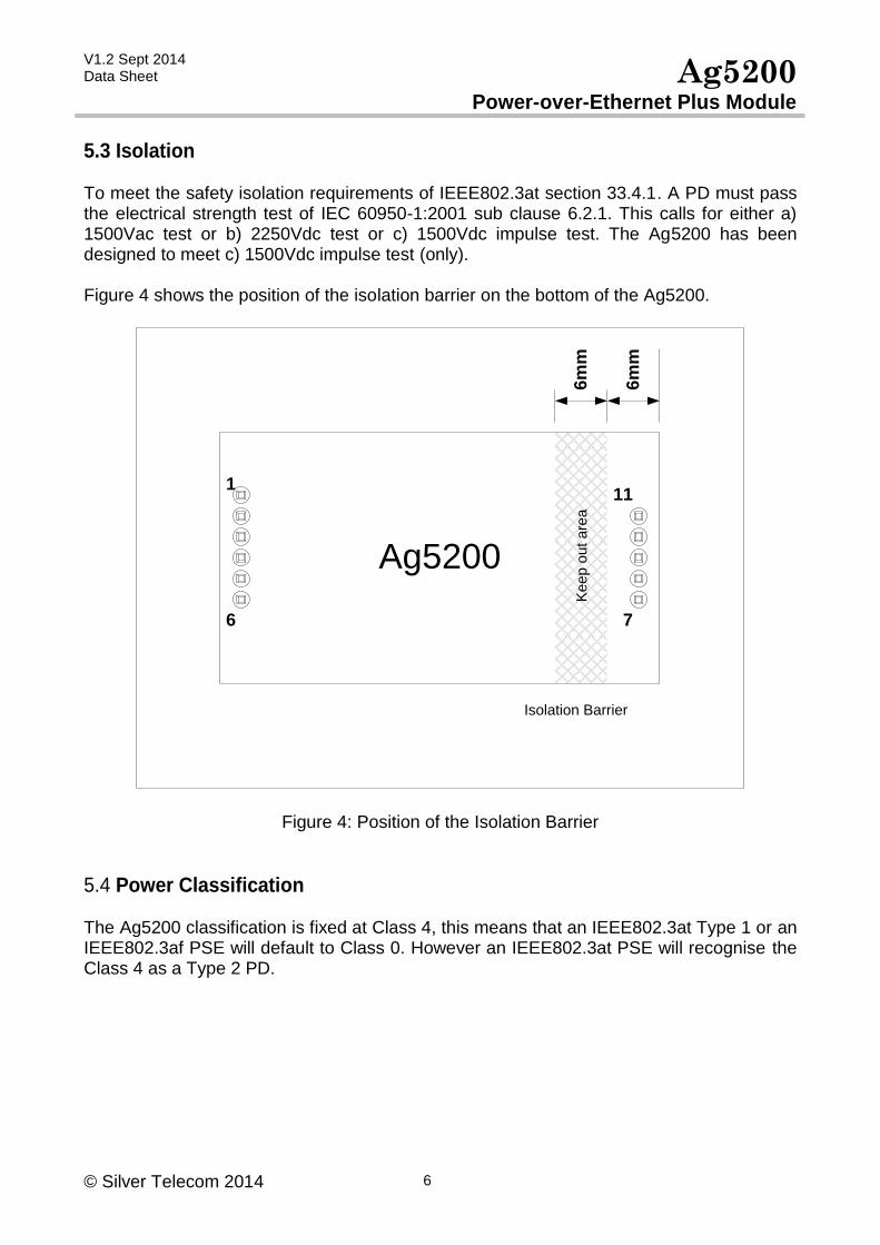
5.3 Isolation To meet the safety isolation requirements of IEEE802.3at section 33.4.1. A PD must pass the electrical strength test of IEC 60950-1:2001 sub clause 6.2.1. This calls for either a) 1500Vac test or b) 2250Vdc test or c) 1500Vdc impulse test. The Ag5200 has been designed to meet c) 1500Vdc impulse test (only). Figure 4 shows the position of the isolation barrier on the bottom of the Ag5200.
6m
m
1
6
Ag5200
7
11
6m
mK
ee
p o
ut a
rea
Isolation Barrier
Figure 4: Position of the Isolation Barrier
5.4 Power Classification The Ag5200 classification is fixed at Class 4, this means that an IEEE802.3at Type 1 or an IEEE802.3af PSE will default to Class 0. However an IEEE802.3at PSE will recognise the Class 4 as a Type 2 PD.
V1.2 Sept 2014 Data Sheet Ag5200
Power-over-Ethernet Plus Module
© Silver Telecom 2014 7
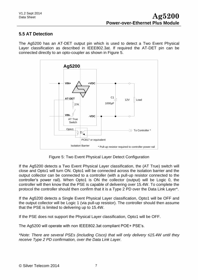
5.5 AT Detection The Ag5200 has an AT-DET output pin which is used to detect a Two Event Physical Layer classification as described in IEEE802.3at. If required the AT-DET pin can be connected directly to an opto-coupler as shown in Figure 5.
Ag5200
VIN-
VIN+
AT-DET C1
1000µF
12V Load+
Isolation Barrier
Opto1 To Controller *
* Pull-up resistor required to controller power rail
27K
AT True
Switch
PC817 or equivalent
+VDC
-VDC
Figure 5: Two Event Physical Layer Detect Configuration If the Ag5200 detects a Two Event Physical Layer classification, the (AT True) switch will close and Opto1 will turn ON. Opto1 will be connected across the isolation barrier and the output collector can be connected to a controller (with a pull-up resistor connected to the controller’s power rail). When Opto1 is ON the collector (output) will be Logic 0, the controller will then know that the PSE is capable of delivering over 15.4W. To complete the protocol the controller should then confirm that it is a Type 2 PD over the Data Link Layer*. If the Ag5200 detects a Single Event Physical Layer classification, Opto1 will be OFF and the output collector will be Logic 1 (via pull-up resistor). The controller should then assume that the PSE is limited to delivering up to 15.4W. If the PSE does not support the Physical Layer classification, Opto1 will be OFF. The Ag5200 will operate with non IEEE802.3at compliant POE+ PSE’s. *Note: There are several PSEs (including Cisco) that will only delivery ≤15.4W until they receive Type 2 PD confirmation, over the Data Link Layer.
V1.2 Sept 2014 Data Sheet Ag5200
Power-over-Ethernet Plus Module
© Silver Telecom 2014 8
5.6 DC/DC Converter The Ag5200’s DC/DC converter provides a regulated 12V (nominal) output with low ripple and low noise. The DC/DC converter also has built-in output overload and short-circuit protection. The Ag5200 also has thermal protection; which will shutdown the DC/DC converter if exceeded.
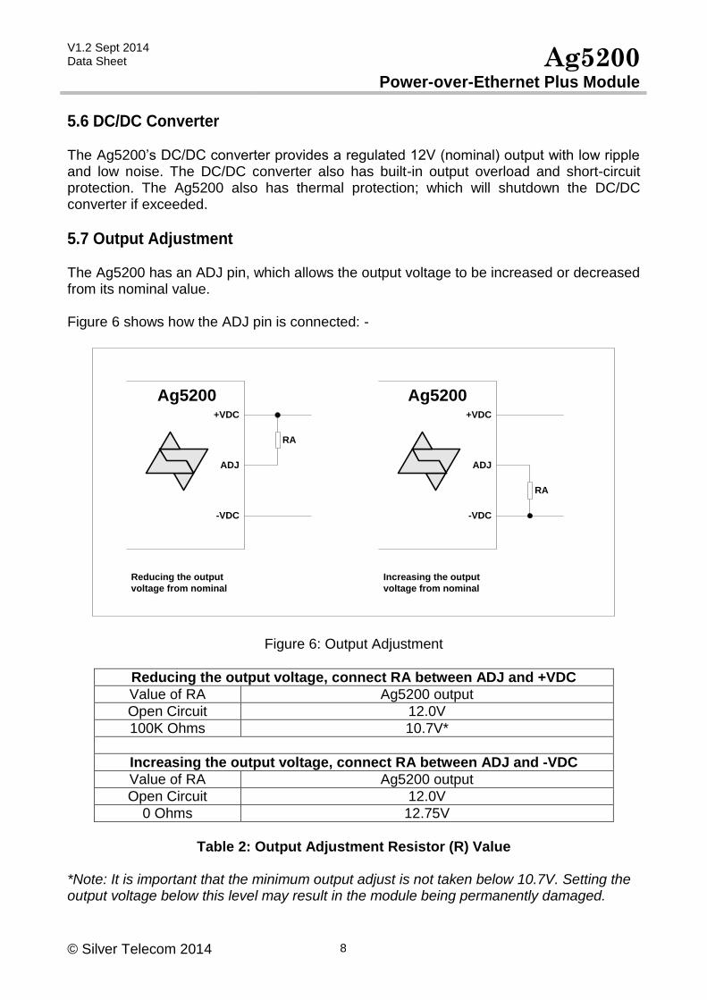
5.7 Output Adjustment The Ag5200 has an ADJ pin, which allows the output voltage to be increased or decreased from its nominal value. Figure 6 shows how the ADJ pin is connected: -
Ag5200+VDC
-VDC
ADJ
Ag5200+VDC
-VDC
ADJ
Increasing the output
voltage from nominal
Reducing the output
voltage from nominal
RA
RA
Figure 6: Output Adjustment
Reducing the output voltage, connect RA between ADJ and +VDC
Value of RA Ag5200 output
Open Circuit 12.0V
100K Ohms 10.7V*
Increasing the output voltage, connect RA between ADJ and -VDC
Value of RA Ag5200 output
Open Circuit 12.0V
0 Ohms 12.75V
Table 2: Output Adjustment Resistor (R) Value
*Note: It is important that the minimum output adjust is not taken below 10.7V. Setting the output voltage below this level may result in the module being permanently damaged.
V1.2 Sept 2014 Data Sheet Ag5200
Power-over-Ethernet Plus Module
© Silver Telecom 2014 9
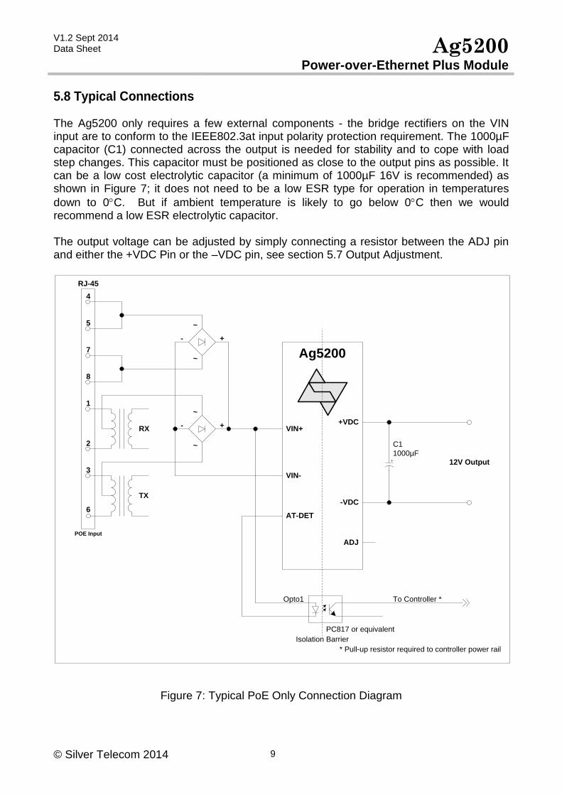
5.8 Typical Connections The Ag5200 only requires a few external components - the bridge rectifiers on the VIN input are to conform to the IEEE802.3at input polarity protection requirement. The 1000µF capacitor (C1) connected across the output is needed for stability and to cope with load step changes. This capacitor must be positioned as close to the output pins as possible. It can be a low cost electrolytic capacitor (a minimum of 1000µF 16V is recommended) as shown in Figure 7; it does not need to be a low ESR type for operation in temperatures
down to 0C. But if ambient temperature is likely to go below 0C then we would recommend a low ESR electrolytic capacitor. The output voltage can be adjusted by simply connecting a resistor between the ADJ pin and either the +VDC Pin or the –VDC pin, see section 5.7 Output Adjustment.
Ag5200
RX
TX
4
5
1
2
3
6
7
8
VIN+
AT-DET
ADJ
12V Output
RJ-45
VIN-
+-
~
~
+-
~
~
+VDC
-VDC
POE Input
Isolation Barrier
* Pull-up resistor required to controller power rail
Opto1 To Controller *
PC817 or equivalent
+
C1
1000µF
Figure 7: Typical PoE Only Connection Diagram
V1.2 Sept 2014 Data Sheet Ag5200
Power-over-Ethernet Plus Module
© Silver Telecom 2014 10
5.9 Output Power The Ag5200 is capable of delivering a maximum output power of 30W continuous; however this is limited by the available input power and operating temperature. When calculating the output power, the following factors must be taken into account: -
1. Ag5200 efficiency 2. PSE output power (which could be limited by the IEEE802.3at specification) 3. Cable and connector losses 4. Input bridge rectifier losses 5. Operating temperature
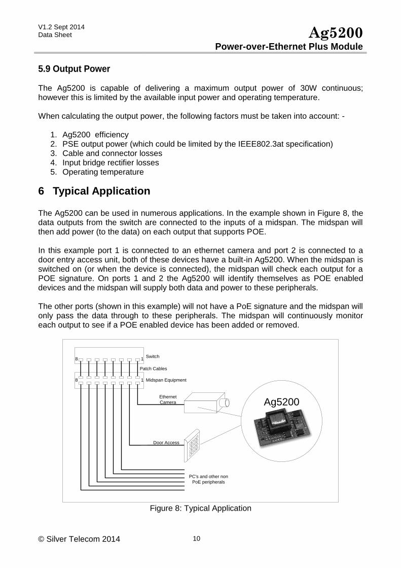
6 Typical Application The Ag5200 can be used in numerous applications. In the example shown in Figure 8, the data outputs from the switch are connected to the inputs of a midspan. The midspan will then add power (to the data) on each output that supports POE. In this example port 1 is connected to an ethernet camera and port 2 is connected to a door entry access unit, both of these devices have a built-in Ag5200. When the midspan is switched on (or when the device is connected), the midspan will check each output for a POE signature. On ports 1 and 2 the Ag5200 will identify themselves as POE enabled devices and the midspan will supply both data and power to these peripherals. The other ports (shown in this example) will not have a PoE signature and the midspan will only pass the data through to these peripherals. The midspan will continuously monitor each output to see if a POE enabled device has been added or removed.
Ag5200Ethernet
Camera
Door Access
Midspan Equipment
Switch
Patch Cables
PC's and other non
PoE peripherals
18
18
Figure 8: Typical Application
V1.2 Sept 2014 Data Sheet Ag5200
Power-over-Ethernet Plus Module
© Silver Telecom 2014 11
7 Operating Temperature Range Because the Ag5200 is a power component, it will generate heat; so it is important that this be taken into consideration at the design stage. The heart of the Ag5200 is a DC/DC converter, which like any other power supply will generate heat. The amount of heat generated by the module will depend on the load it is required to drive and the input voltage supplied by the PSE. The information shown within this section of datasheet is referenced to a nominal 52Vdc input voltage supplied by the PSE. Because each application is different it is impossible to give fixed and absolute thermal recommendations. However to obtain maximum power it is important that any enclosure used has sufficient ventilation and forced airflow over the Ag5200.
When intended for used in ambient temperatures below 0C we would recommend a low
ESR electrolytic capacitor be used on the DC output. Capacitors rated for -55C operation
should be used below -20C.
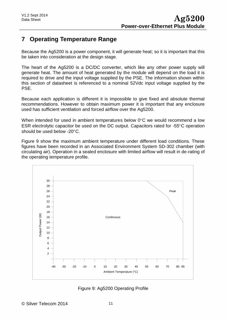
Figure 9 show the maximum ambient temperature under different load conditions. These figures have been recorded in an Associated Environment System SD-302 chamber (with circulating air). Operation in a sealed enclosure with limited airflow will result in de-rating of the operating temperature profile.
-20 -10 0 10 20 30 40 50 60 70
2
8
4
10
6
Ou
tpu
t P
ow
er
(W)
Ambient Temperature (°C)
12
14
16
18
20
22
24
26
28
30
Continuous
Peak
80 85-30-40
Figure 9: Ag5200 Operating Profile
V1.2 Sept 2014 Data Sheet Ag5200
Power-over-Ethernet Plus Module
© Silver Telecom 2014 12
8 Protection The Ag5200 has built-in over-current and thermal protection to prevent the module from being damaged if operated beyond its power / temperature specification. If a short circuit is applied to the output, the DC/DC converter will limit the current until the short circuit is removed. If the maximum operating temperature is exceeded; the thermal protection circuit will disable the DC/DC converter until the Ag5200 temperature has cooled sufficiently. The Ag5200 may be damaged by input voltage transients greater than 80V. If protection from electrostatic discharge (ESD) or other high voltage transients is required, it is recommended that over-voltage clamping devices are fitted across the VIN and AUX inputs. Typically an SMAJ58 will be sufficient; see Apps Note “ANX-POE-Protection”.
9 EMC The Ag5200 has been designed to pass EN55022 Class b. However the module will only be one component within a system. So it is impossible to say whether the final product will pass EMC testing without the need for additional filtering. The Ag5200 uses a DC/DC converter which runs at ~250KHz. Additional filtering information can be found in apps note “ANX-POE-EMI”.
10 Electrical Characteristics
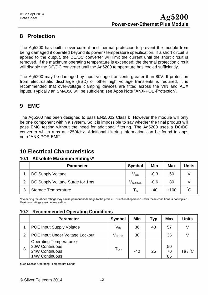
10.1 Absolute Maximum Ratings* Parameter Symbol Min Max Units
1 DC Supply Voltage VCC -0.3 60 V
2 DC Supply Voltage Surge for 1ms VSURGE -0.6 80 V
3 Storage Temperature TS -40 +100 °C
*Exceeding the above ratings may cause permanent damage to the product. Functional operation under these conditions is not implied. Maximum ratings assume free airflow.
10.2 Recommended Operating Conditions Parameter Symbol Min Typ Max Units
1 POE Input Supply Voltage VIN 36 48 57 V
2 POE Input Under Voltage Lockout VLOCK 30 36 V
3
Operating Temperature † 30W Continuous 24W Continuous 14W Continuous
TOP
-40
25
50 70 85
Ta / °C
†See Section Operating Temperature Range
V1.2 Sept 2014 Data Sheet Ag5200
Power-over-Ethernet Plus Module
© Silver Telecom 2014 13
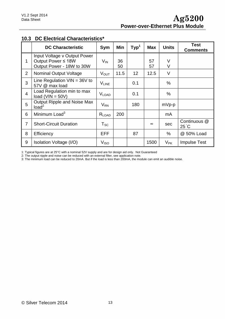
10.3 DC Electrical Characteristics*
DC Characteristic Sym Min Typ1 Max Units Test
Comments
1 Input Voltage v Output Power Output Power ≤ 18W Output Power - 18W to 30W
VIN
36 50
57 57
V V
2 Nominal Output Voltage VOUT 11.5 12 12.5 V
3 Line Regulation VIN = 36V to 57V @ max load
VLINE 0.1 %
4 Load Regulation min to max load (VIN = 50V)
VLOAD 0.1 %
5 Output Ripple and Noise Max load2
VRN 180 mVp-p
6 Minimum Load3 RLOAD 200 mA
7 Short-Circuit Duration TSC ∞ sec Continuous @ 25 °C
8 Efficiency EFF 87 % @ 50% Load
9 Isolation Voltage (I/O) VISO 1500 VPK Impulse Test
1: Typical figures are at 25°C with a nominal 52V supply and are for design aid only. Not Guaranteed 2: The output ripple and noise can be reduced with an external filter, see application note. 3: The minimum load can be reduced to 20mA. But if the load is less than 200mA, the module can emit an audible noise.
V1.2 Sept 2014 Data Sheet Ag5200
Power-over-Ethernet Plus Module
© Silver Telecom 2014 14
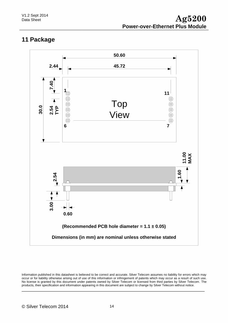
11 Package
0.60
45.72
7.4
0
(Recommended PCB hole diameter = 1.1 ± 0.05)
Dimensions (in mm) are nominal unless otherwise stated
2.44
50.602.5
4
TY
P
30
.0
2.5
43
.00
1.6
01
1.0
0
MA
X
1
6
Top
View7
11
Information published in this datasheet is believed to be correct and accurate. Silver Telecom assumes no liability for errors which may occur or for liability otherwise arising out of use of this information or infringement of patents which may occur as a result of such use. No license is granted by this document under patents owned by Silver Telecom or licensed from third parties by Silver Telecom. The products, their specification and information appearing in this document are subject to change by Silver Telecom without notice.