Embed Size (px)
DESCRIPTION
Product Catalogue 0511
Citation preview
93/1844
Machinery Safety Guardsand Safety Accessories
British made for over 60 years
ISSUE THREE
93/1844
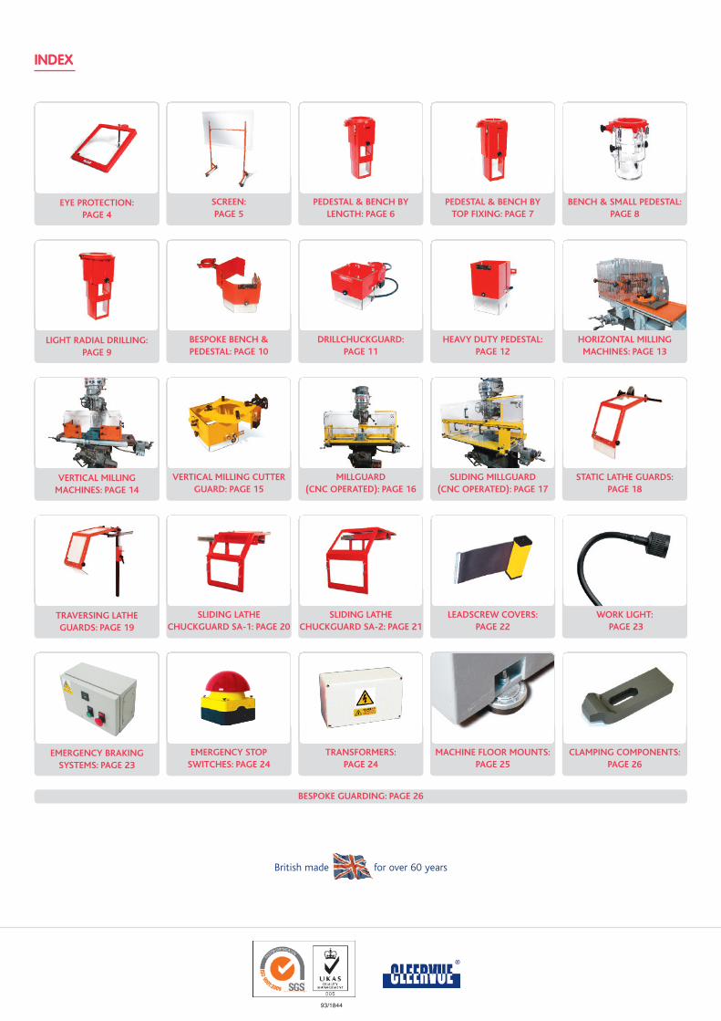
INDEX
British made for over 60 years
EYE PROTECTION:PAGE 4
SCREEN: PAGE 5
PEDESTAL & BENCH BYLENGTH: PAGE 6
PEDESTAL & BENCH BYTOP FIXING: PAGE 7
BENCH & SMALL PEDESTAL: PAGE 8
LIGHT RADIAL DRILLING:PAGE 9
BESPOKE BENCH & PEDESTAL: PAGE 10
DRILLCHUCKGUARD: PAGE 11
HEAVY DUTY PEDESTAL:PAGE 12
HORIZONTAL MILLINGMACHINES: PAGE 13
VERTICAL MILLINGMACHINES: PAGE 14
VERTICAL MILLING CUTTERGUARD: PAGE 15
MILLGUARD (CNC OPERATED): PAGE 16
SLIDING MILLGUARD (CNC OPERATED): PAGE 17
STATIC LATHE GUARDS:PAGE 18
TRAVERSING LATHE GUARDS: PAGE 19
SLIDING LATHE CHUCKGUARD SA-1: PAGE 20
SLIDING LATHE CHUCKGUARD SA-2: PAGE 21
LEADSCREW COVERS:PAGE 22
WORK LIGHT:PAGE 23
EMERGENCY BRAKINGSYSTEMS: PAGE 23
EMERGENCY STOP SWITCHES: PAGE 24
TRANSFORMERS:PAGE 24
MACHINE FLOOR MOUNTS:PAGE 25
CLAMPING COMPONENTS:PAGE 26
BESPOKE GUARDING: PAGE 26
INTRODUCTION
PRODUCT INFORMATION AND ORDERING PROCEDURE
polyCarbonaTe While polycarbonate has very high impact strength
good scratch resistance and is strongly recommended for transparent visors
in safety guards it is subject to age hardening and is degraded by certain
cuttings fluids.
While every effort has been made both in design and manufacture to reduce
the harmful effect of cutting fluids stress cracking may still occur and this is
totally beyond our control.
All ancillary components, nuts, bolts and washers are bright zinc plated or
chemically treated ensuring a rust free and a good long lasting appearance.
All metalwork and aluminium castings used in our products are epoxy coated
distinguishing the guard from the machine tool.
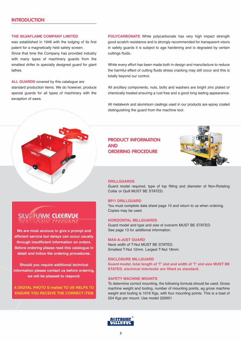
DrillguArDS
Guard model required, type of top fitting and diameter of Non-Rotating
Collar or Quill MUST BE STATED.
Bp/1 DrillguArD
You must complete data sheet page 10 and return to us when ordering.
Copies may be used.
horiZontAl MillguArDS
Guard model and type and size of overarm MUST BE STATED.
See page 13 for additional information.
MAX-A-JuSt guArD
Neck width of T-Nut MUST BE STATED.
Smallest T-Nut 12mm. Largest T-Nut 18mm.
encloSure MillguArD
Guard model, total length of ‘T’ slot and width of ‘T’ slot size MUST BE STATED, electrical interlocks are fitted as standard.
SAFety MAchine MountS
To determine correct mounting, the following formula should be used. Gross
machine weight and tooling, number of mounting points, eg gross machine
weight and tooling is 1016 Kgs, with four mounting points. This is a load of
254 Kgs per mount. Use model 220001
3
The Silvaflame Company limiTed
was established in 1946 with the lodging of its first
patent for a magnetically held safety screen.
Since that time the Company has provided industry
with many types of machinery guards from the
smallest driller to specially designed guard for giant
lathes.
all guardS covered by this catalogue are
standard production items. We do however, produce
special guards for all types of machinery with the
exception of saws.
We are most anxious to give a prompt and
efficient service but delays can occur usually
through insufficient information on orders.
Before ordering please read this catalogue in
detail and follow the ordering procedures.
Should you require additional technical
information please contact us before ordering,
we will be pleased to respond.
A DigitAl photo e-mailed to uS helpS to
enSure you receive the correct iteM
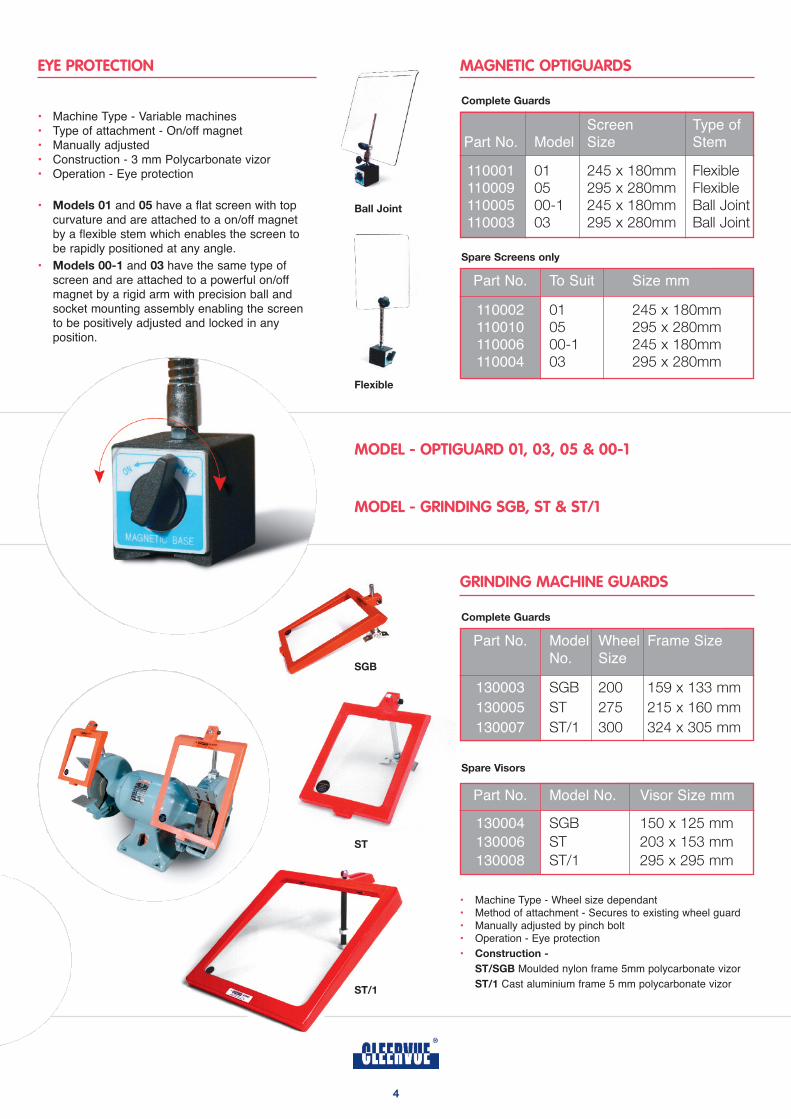
EYE PROTECTION
MODEL - OPTIGUARD 01, 03, 05 & 00-1
MODEL - GRINDING SGB, ST & ST/1
GRINDING MACHINE GUARDS
MAGNETIC OPTIGUARDS
• Machine Type - Variable machines• Type of attachment - On/off magnet• Manually adjusted• Construction - 3 mm Polycarbonate vizor• Operation - Eye protection
• models 01 and 05 have a flat screen with top curvature and are attached to a on/off magnet by a flexible stem which enables the screen to be rapidly positioned at any angle.
• models 00-1 and 03 have the same type of screen and are attached to a powerful on/off magnet by a rigid arm with precision ball and socket mounting assembly enabling the screen to be positively adjusted and locked in any position.
Screen Type ofPart No. Model Size Stem
110001 01 245 x 180mm Flexible110009 05 295 x 280mm Flexible110005 00-1 245 x 180mm Ball Joint110003 03 295 x 280mm Ball Joint
Part No. To Suit Size mm
110002 01 245 x 180mm110010 05 295 x 280mm110006 00-1 245 x 180mm110004 03 295 x 280mm
Spare Screens only
Part No. Model Wheel Frame SizeNo. Size
130003 SGB 200 159 x 133 mm
130005 ST 275 215 x 160 mm
130007 ST/1 300 324 x 305 mm
Part No. Model No. Visor Size mm
130004 SGB 150 x 125 mm
130006 ST 203 x 153 mm
130008 ST/1 295 x 295 mm
Complete guards
Complete guards
Spare visors
• Machine Type - Wheel size dependant• Method of attachment - Secures to existing wheel guard• Manually adjusted by pinch bolt• Operation - Eye protection
• Construction -
ST/Sgb Moulded nylon frame 5mm polycarbonate vizor
ST/1 Cast aluminium frame 5 mm polycarbonate vizor
4
ST
ball Joint
flexible
ST/1
Sgb
5
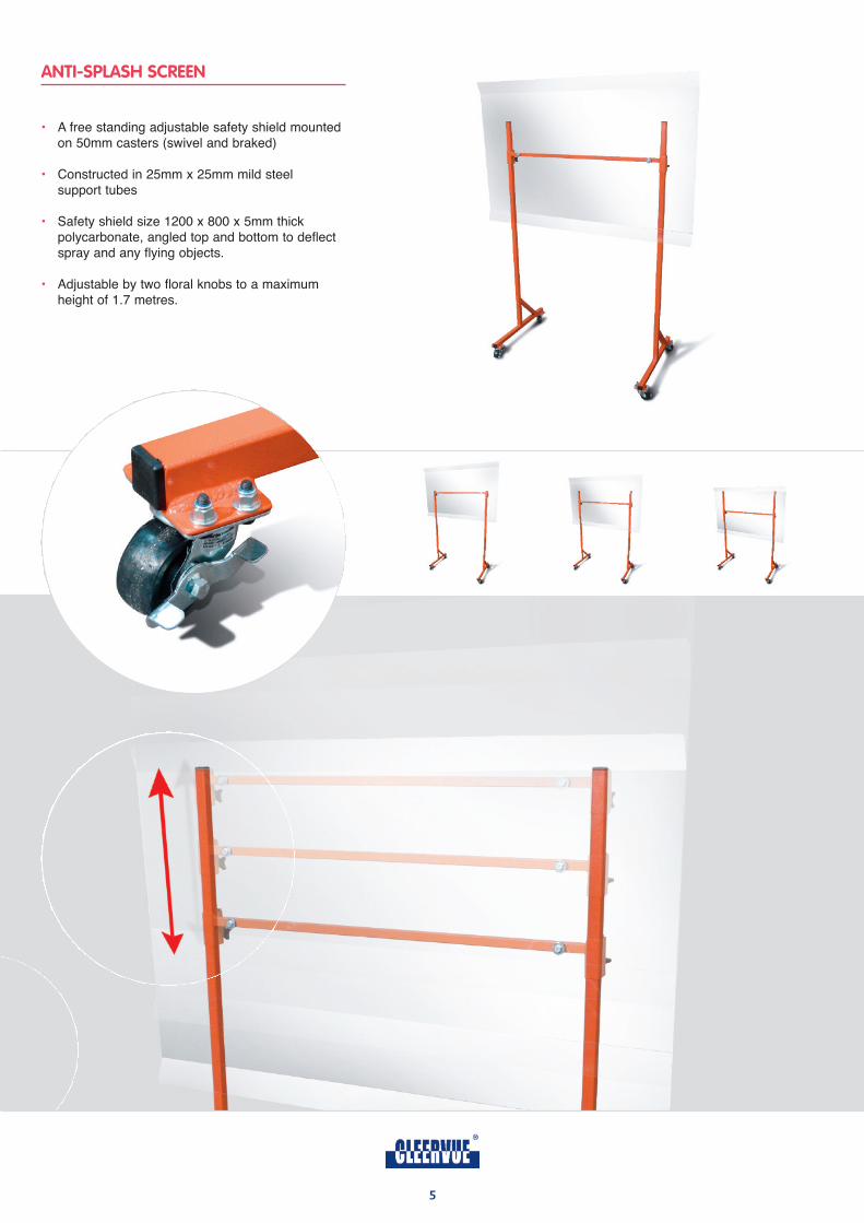
ANTI-SPLASH SCREEN
• A free standing adjustable safety shield mounted on 50mm casters (swivel and braked)
• Constructed in 25mm x 25mm mild steel support tubes
• Safety shield size 1200 x 800 x 5mm thick polycarbonate, angled top and bottom to deflect spray and any flying objects.
• Adjustable by two floral knobs to a maximum height of 1.7 metres.
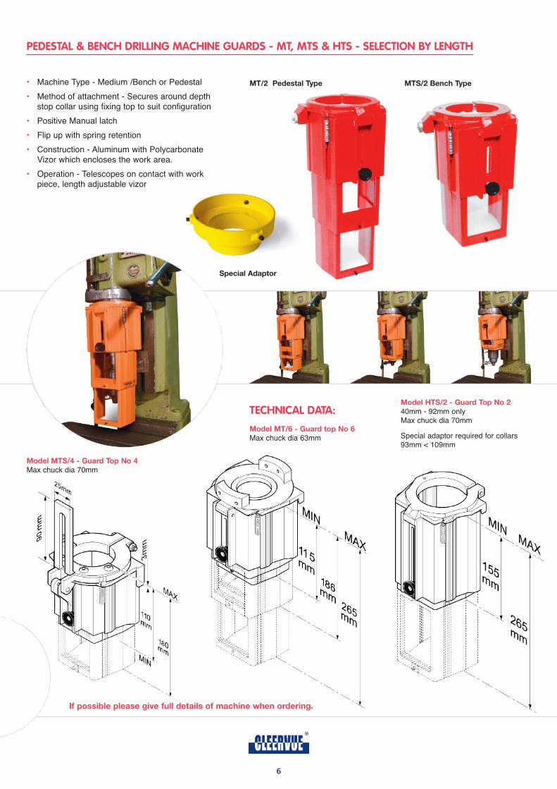
PEDESTAL & BENCH DRILLING MACHINE GUARDS - MT, MTS & HTS - SELECTION BY LENGTH
6
TECHNICAL DATA:
model mT/6 - guard top no 6
Max chuck dia 63mm
mTS/2 bench TypemT/2 pedestal Type
model mTS/4 - guard Top no 4
Max chuck dia 70mm
if possible please give full details of machine when ordering.
model hTS/2 - guard Top no 2
40mm - 92mm onlyMax chuck dia 70mm
Special adaptor required for collars93mm < 109mm
• Machine Type - Medium /Bench or Pedestal
• Method of attachment - Secures around depth stop collar using fixing top to suit configuration
• Positive Manual latch
• Flip up with spring retention
• Construction - Aluminum with Polycarbonate Vizor which encloses the work area.
• Operation - Telescopes on contact with work piece, length adjustable vizor
Special adaptor
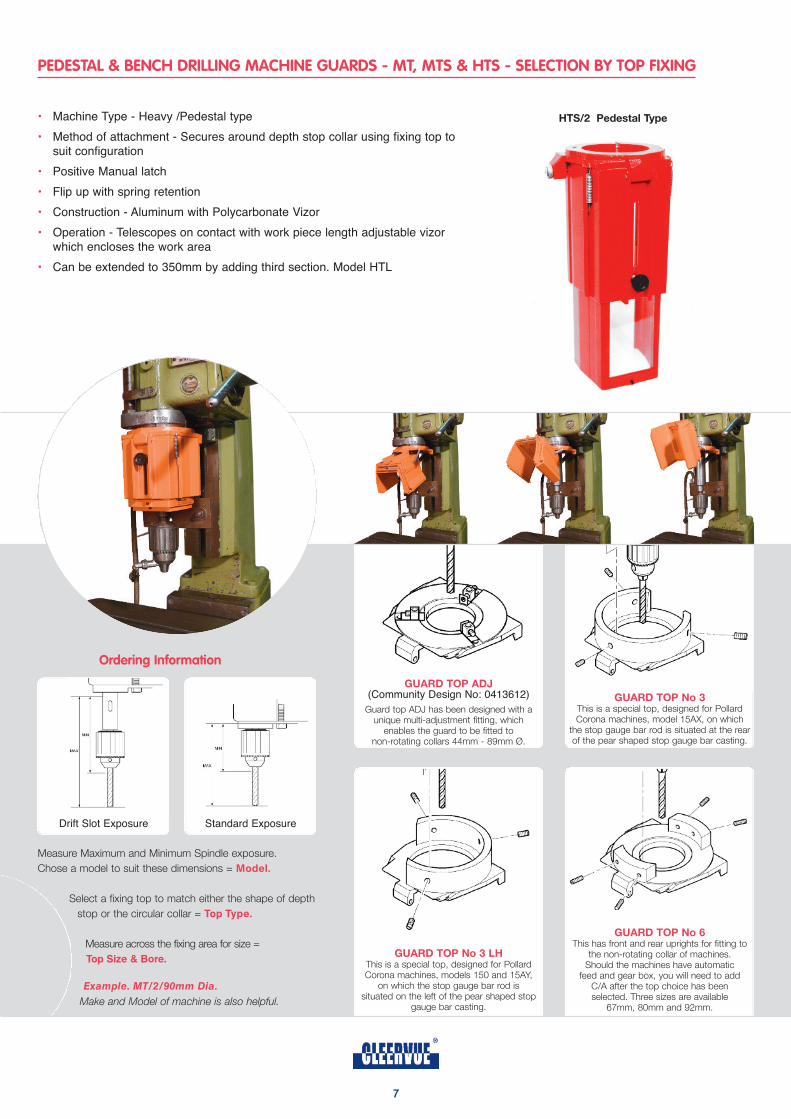
guard Top no 3This is a special top, designed for PollardCorona machines, model 15AX, on which
the stop gauge bar rod is situated at the rearof the pear shaped stop gauge bar casting.
Ordering Information
Drift Slot Exposure Standard Exposure
Measure Maximum and Minimum Spindle exposure.
Chose a model to suit these dimensions = Model.
Select a fixing top to match either the shape of depth
stop or the circular collar = Top Type.
Measure across the fixing area for size =
Top Size & Bore.
Example. MT/2/90mm Dia.
Make and Model of machine is also helpful.
guard Top no 6This has front and rear uprights for fitting to
the non-rotating collar of machines. Should the machines have automatic
feed and gear box, you will need to add C/A after the top choice has been selected. Three sizes are available
67mm, 80mm and 92mm.
guard Top adJ (Community Design No: 0413612)
Guard top ADJ has been designed with aunique multi-adjustment fitting, which
enables the guard to be fitted to non-rotating collars 44mm - 89mm Ø.
guard Top no 3 lhThis is a special top, designed for PollardCorona machines, models 150 and 15AY,
on which the stop gauge bar rod is situated on the left of the pear shaped stop
gauge bar casting.
7
PEDESTAL & BENCH DRILLING MACHINE GUARDS - MT, MTS & HTS - SELECTION BY TOP FIXING
• Machine Type - Heavy /Pedestal type
• Method of attachment - Secures around depth stop collar using fixing top to suit configuration
• Positive Manual latch
• Flip up with spring retention
• Construction - Aluminum with Polycarbonate Vizor
• Operation - Telescopes on contact with work piece length adjustable vizor which encloses the work area
• Can be extended to 350mm by adding third section. Model HTL
hTS/2 pedestal Type
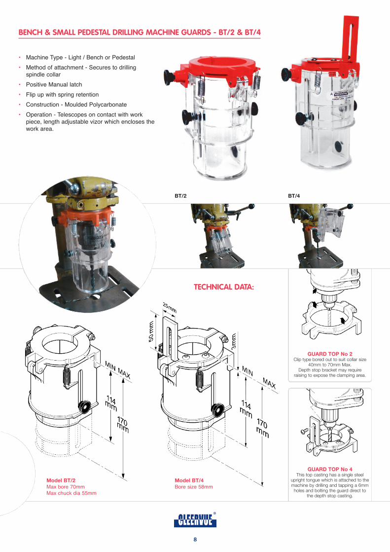
BENCH & SMALL PEDESTAL DRILLING MACHINE GUARDS - BT/2 & BT/4
8
TECHNICAL DATA:
• Machine Type - Light / Bench or Pedestal
• Method of attachment - Secures to drilling spindle collar
• Positive Manual latch
• Flip up with spring retention
• Construction - Moulded Polycarbonate
• Operation - Telescopes on contact with work piece, length adjustable vizor which encloses thework area.
model bT/2
Max bore 70mmMax chuck dia 55mm
model bT/4
Bore size 58mm
guard Top no 2Clip type bored out to suit collar size
40mm to 70mm Max.Depth stop bracket may require
raising to expose the clamping area.
guard Top no 4This top casting has a single steel
upright tongue which is attached to themachine by drilling and tapping a 6mm
holes and bolting the guard direct to the depth stop casting.
bT/4bT/2
guard Top no 1This is for fitting under the Bearing
Housing and can take the place of thedust cover plate. Where quill retractsinto the Head it is fitted by drilling and
tapping the underneath side of the headand bolted by means of countersunk
screws to the machine.
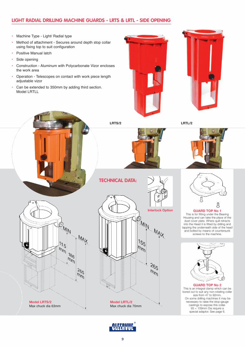
LIGHT RADIAL DRILLING MACHINE GUARDS - LRTS & LRTL - SIDE OPENING
TECHNICAL DATA:
model lrTS/2
Max chuck dia 63mmmodel lrTl/2
Max chuck dia 70mm
• Machine Type - Light/ Radial type
• Method of attachment - Secures around depth stop collar using fixing top to suit configuration
• Positive Manual latch
• Side opening
• Construction - Aluminum with Polycarbonate Vizor encloses the work area
• Operation - Telescopes on contact with work piece length adjustable vizor
• Can be extended to 350mm by adding third section. Model LRTLL
lrTS/2 lrTl/2
9
guard Top no 2This is an integral clamp which can be
bored out to suit any non-rotating collarsize from 47 to 92mm.
On some drilling machines it may benecessary to raise the stop-gauge
castings to expose this collar.93 < 109mm Dia require a
special adaptor. See page 6.
interlock option
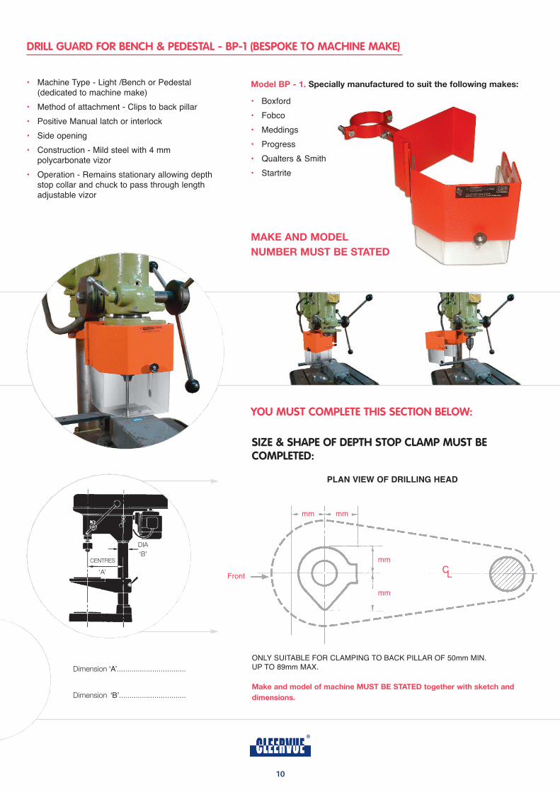
DRILL GUARD FOR BENCH & PEDESTAL - BP-1 (BESPOKE TO MACHINE MAKE)
10
YOU MUST COMPLETE THIS SECTION BELOW:
• Machine Type - Light /Bench or Pedestal (dedicated to machine make)
• Method of attachment - Clips to back pillar
• Positive Manual latch or interlock
• Side opening
• Construction - Mild steel with 4 mm polycarbonate vizor
• Operation - Remains stationary allowing depth stop collar and chuck to pass through length adjustable vizor
model bp - 1. Specially manufactured to suit the following makes:
• Boxford
• Fobco
• Meddings
• Progress
• Qualters & Smith
• Startrite
make and model
number muST be STaTed
Dimension ‘A’.................................
Dimension ‘B’................................
ONLY SUITABLE FOR CLAMPING TO BACK PILLAR OF 50mm MIN. UP TO 89mm MAX.
make and model of machine muST be STaTed together with sketch and
dimensions.
SIZE & SHAPE OF DEPTH STOP CLAMP MUST BE COMPLETED:
plAn vieW oF Drilling heAD
Front
mm mm
mm
mm
CL
DIA
‘B’CENTRES
‘A’
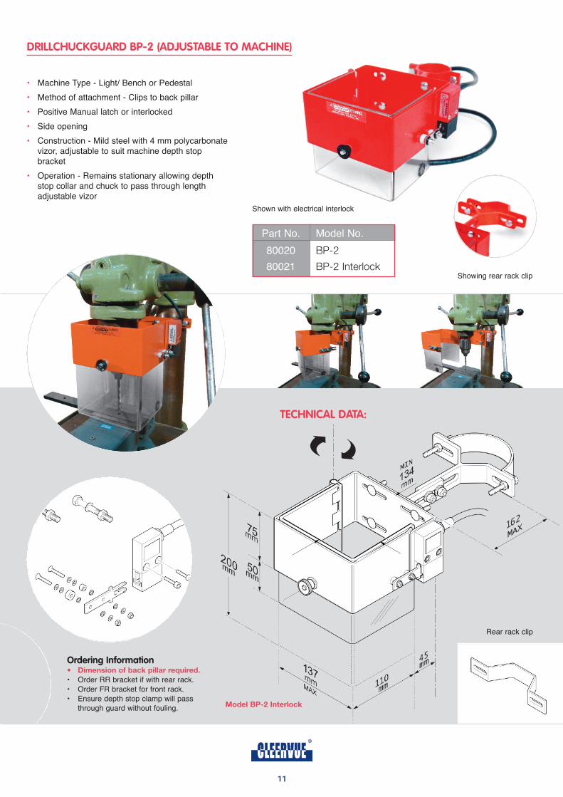
DRILLCHUCKGUARD BP-2 (ADJUSTABLE TO MACHINE)
TECHNICAL DATA:
Ordering Information• dimension of back pillar required.
• Order RR bracket if with rear rack.
• Order FR bracket for front rack.
• Ensure depth stop clamp will pass
through guard without fouling. model bp-2 interlock
• Machine Type - Light/ Bench or Pedestal
• Method of attachment - Clips to back pillar
• Positive Manual latch or interlocked
• Side opening
• Construction - Mild steel with 4 mm polycarbonate vizor, adjustable to suit machine depth stop bracket
• Operation - Remains stationary allowing depth stop collar and chuck to pass through length adjustable vizor
Rear rack clip
Part No. Model No.
80020 BP-2
80021 BP-2 Interlock
Shown with electrical interlock
Showing rear rack clip
11
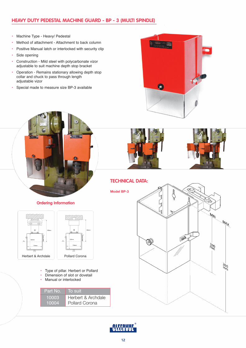
HEAVY DUTY PEDESTAL MACHINE GUARD - BP - 3 (MULTI SPINDLE)
12
TECHNICAL DATA:
• Machine Type - Heavy/ Pedestal
• Method of attachment - Attachment to back column
• Positive Manual latch or interlocked with security clip
• Side opening
• Construction - Mild steel with polycarbonate vizor adjustable to suit machine depth stop bracket
• Operation - Remains stationary allowing depth stop collar and chuck to pass through length adjustable vizor
• Special made to measure size BP-3 available
model bp-3
Ordering Information
Herbert & Archdale Pollard Corona
• Type of pillar. Herbert or Pollard• Dimension of slot or dovetail• Manual or interlocked
Part No. To suit
10003 Herbert & Archdale10004 Pollard Corona
13
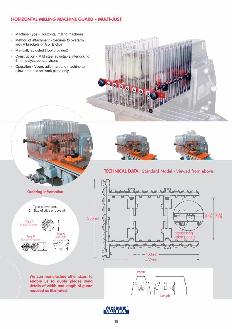
355mm
400mm
432mm
203mm
280mm
Interlocking vision panels
HORIZONTAL MILLING MACHINE GUARD - MULTI-JUST
TECHNICAL DATA: Standard Model - Viewed from above
• Machine Type - Horizontal milling machines
• Method of attachment - Secures to overarm with V brackets or A or B clips
• Manually adjusted (Tool provided)
• Construction - Mild steel adjustable interlocking 6 mm polycarbonate visors
• Operation - Vizors adjust around machine to allow entrance for work piece only
Type ASingle Overarm D
Type CVee SlideType B
Double Overarm
DW
1. Type of overarm.2. Size of clips or dovetail.
Ordering Information
Width
Length
We can manufacture other sizes, toenable us to quote please senddetails of width and length of guardrequired as illustrated.
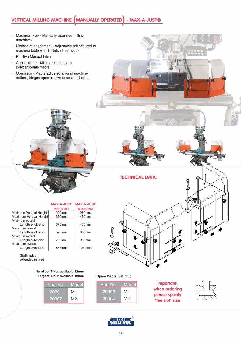
VERTICAL MILLING MACHINE MANUALLY OPERATED - MAX-A-JUST®
14
• Machine Type - Manually operated milling machines
• Method of attachment - Adjustable rail secured tomachine table with T. Nuts (1 per side)
• Positive Manual latch
• Construction - Mild steel adjustable polycarbonate visors
• Operation - Vizors adjusted around machine cutters, hinges open to give access to tooling
maX-a-JuST maX-a-JuST
model m1 model m2
Minimum Vertical Height 200mm 250mmMaximum Vertical Height 350mm 450mmMinimum overall
Length enclosing 375mm 475mmMaximum overall
Length enclosing 525mm 800mmMinimum overall
Length extended 700mm 925mmMaximum overall
Length extended 875mm 1250mm
(Both sides extended in line)
important:when ordering please specify ‘tee slot’ size
Part No. Model
20001 M1
20002 M2
Part No. Model
20003 M1
20004 M2
Spare visors (Set of 6)
Smallest T-nut available 12mm
largest T-nut available 18mm
TECHNICAL DATA:
( )
15
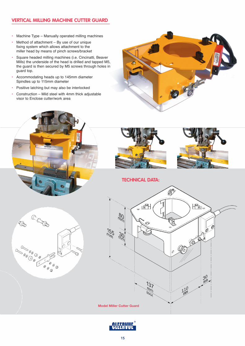
VERTICAL MILLING MACHINE CUTTER GUARD
• Machine Type – Manually operated milling machines
• Method of attachment – By use of our unique fixing system which allows attachment to the miller head by means of pinch screws/bracket
• Square headed milling machines (i.e. Cincinatti, Beaver Mills) the underside of the head is drilled and tapped M5,the guard is then secured by M5 screws through holes inguard top.
• Accommodating heads up to 145mm diameter Spindles up to 115mm diameter
• Positive latching but may also be interlocked
• Construction – Mild steel with 4mm thick adjustable visor to Enclose cutter/work area
TECHNICAL DATA:
model miller Cutter guard
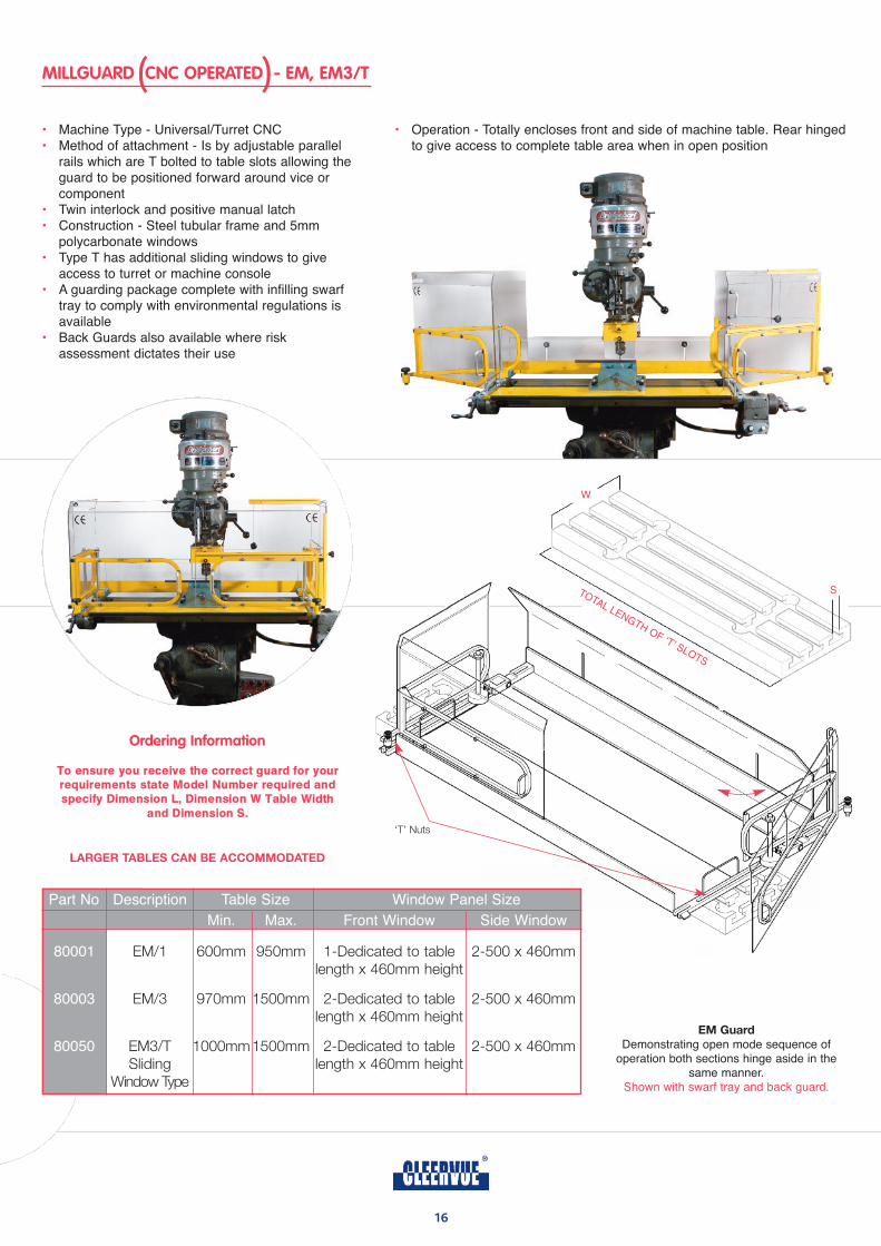
MILLGUARD CNC OPERATED - EM, EM3/T
16
• Machine Type - Universal/Turret CNC• Method of attachment - Is by adjustable parallel
rails which are T bolted to table slots allowing theguard to be positioned forward around vice or component
• Twin interlock and positive manual latch• Construction - Steel tubular frame and 5mm
polycarbonate windows• Type T has additional sliding windows to give
access to turret or machine console• A guarding package complete with infilling swarf
tray to comply with environmental regulations is available
• Back Guards also available where risk assessment dictates their use
• Operation - Totally encloses front and side of machine table. Rear hingedto give access to complete table area when in open position
Ordering Information
To ensure you receive the correct guard for your requirements state Model Number required andspecify Dimension L, Dimension W Table Width
and Dimension S.
S
W
‘T’ Nuts
larger TableS Can be aCCommodaTed
TOTAL LENGTH OF ‘T’ SLOTS
em guard
Demonstrating open mode sequence ofoperation both sections hinge aside in the
same manner.Shown with swarf tray and back guard.
Part No Description Table Size Window Panel Size
Min. Max. Front Window Side Window
80001 EM/1 600mm 950mm 1-Dedicated to table 2-500 x 460mmlength x 460mm height
80003 EM/3 970mm 1500mm 2-Dedicated to table 2-500 x 460mmlength x 460mm height
80050 EM3/T 1000mm1500mm 2-Dedicated to table 2-500 x 460mmSliding length x 460mm height
Window Type
( )
17
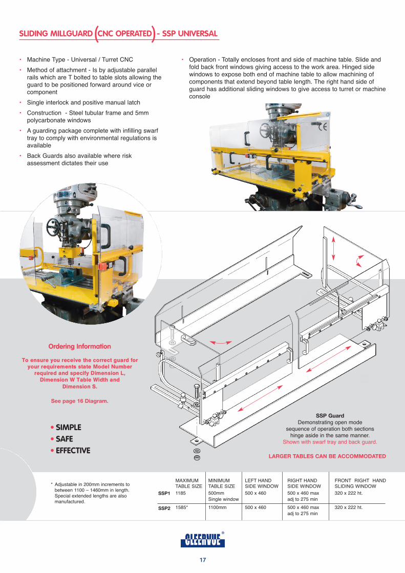
SLIDING MILLGUARD CNC OPERATED - SSP UNIVERSAL
• Machine Type - Universal / Turret CNC
• Method of attachment - Is by adjustable parallel rails which are T bolted to table slots allowing theguard to be positioned forward around vice or component
• Single interlock and positive manual latch
• Construction - Steel tubular frame and 5mm polycarbonate windows
• A guarding package complete with infilling swarf tray to comply with environmental regulations is available
• Back Guards also available where risk assessment dictates their use
• Operation - Totally encloses front and side of machine table. Slide and fold back front windows giving access to the work area. Hinged side windows to expose both end of machine table to allow machining of components that extend beyond table length. The right hand side of guard has additional sliding windows to give access to turret or machineconsole
Ordering Information
To ensure you receive the correct guard foryour requirements state Model Number
required and specify Dimension L,Dimension W Table Width and
Dimension S.
See page 16 diagram.
TableLength
LS
W
larger TableS Can be aCCommodaTed
• SIMPLE• SAFE• EFFECTIVE
SSp guard
Demonstrating open mode sequence of operation both sections
hinge aside in the same manner.Shown with swarf tray and back guard.
MAXIMUM MINIMUM LEFT HAND RIGHT HAND FRONT RIGHT HANDTABLE SIZE TABLE SIZE SIDE WINDOW SIDE WINDOW SLIDING WINDOW
1185 500mm 500 x 460 500 x 460 max 320 x 222 ht.
Single window adj to 275 min
1585* 1100mm 500 x 460 500 x 460 max 320 x 222 ht.
adj to 275 min
SSp1
SSp2
* Adjustable in 200mm increments to between 1100 – 1460mm in length.Special extended lengths are also manufactured.
( )
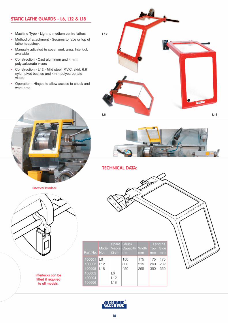
STATIC LATHE GUARDS - L6, L12 & L18
18
TECHNICAL DATA:
• Machine Type - Light to medium centre lathes
• Method of attachment - Secures to face or top of lathe headstock
• Manually adjusted to cover work area. Interlock available
• Construction - Cast aluminum and 4 mm polycarbonate visors
• Construction - L12 - Mild steel, P.V.C. skirt, 6.6 nylon pivot bushes and 4mm polycarbonate visors
• Operation - Hinges to allow access to chuck and work area
Spare Chuck Lengths
Model Visors Capacity Width Top Side
Part No. No. (Set) mm mm mm mm
100001 L6 150 175 175 175
100003 L12 300 215 260 232
100005 L18 450 265 350 350
100002 L6
100004 L12
100006 L18
Electrical Interlock
Interlocks can be fitted if required to all models.
l18
l12
l6
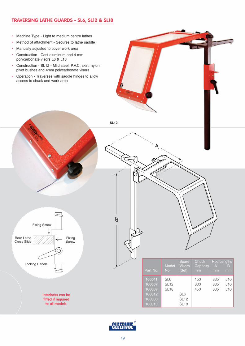
TRAVERSING LATHE GUARDS - SL6, SL12 & SL18
• Machine Type - Light to medium centre lathes
• Method of attachment - Secures to lathe saddle
• Manually adjusted to cover work area
• Construction - Cast aluminum and 4 mm polycarbonate visors L6 & L18
• Construction - SL12 - Mild steel, P.V.C. skirt, nylon pivot bushes and 4mm polycarbonate visors
• Operation - Traverses with saddle hinges to allow access to chuck and work area
Interlocks can be fitted if required to all models.
Fixing Screw
Fixing Screw
Rear LatheCross Slide
Locking Handle
Sl12
Spare Chuck Rod LengthsModel Visors Capacity A B
Part No. No. (Set) mm mm mm
100011 SL6 150 335 510
100007 SL12 300 335 510
100009 SL18 450 335 510
100012 SL6
100008 SL12
100010 SL18
19
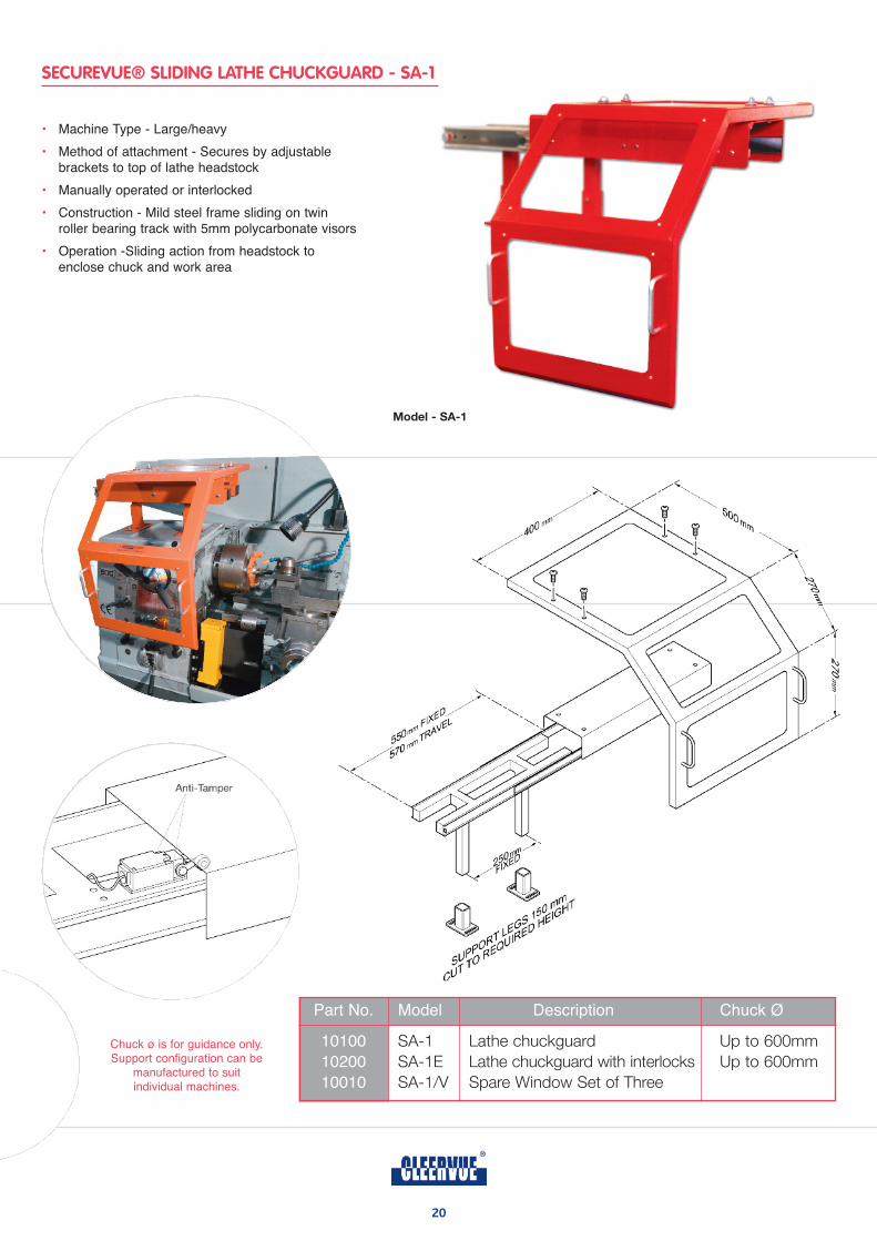
SECUREVUE® SLIDING LATHE CHUCKGUARD - SA-1
20
model - Sa-1
• Machine Type - Large/heavy
• Method of attachment - Secures by adjustable brackets to top of lathe headstock
• Manually operated or interlocked
• Construction - Mild steel frame sliding on twin roller bearing track with 5mm polycarbonate visors
• Operation -Sliding action from headstock to enclose chuck and work area
Part No. Model Description Chuck ø
10100 SA-1 Lathe chuckguard Up to 600mm
10200 SA-1E Lathe chuckguard with interlocks Up to 600mm
10010 SA-1/V Spare Window Set of Three
Chuck ø is for guidance only.Support configuration can be
manufactured to suit individual machines.
21
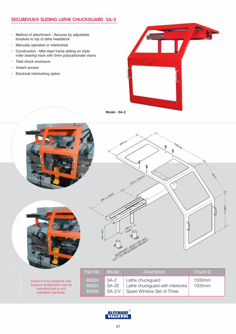
SECUREVUE® SLIDING LATHE CHUCKGUARD SA-2
model - Sa-2
• Method of attachment - Secures by adjustable brackets to top of lathe headstock
• Manually operated or interlocked
• Construction - Mild steel frame sliding on triple roller bearing track with 5mm polycarbonate visors
• Total chuck enclosure
• Instant access
• Electrical interlocking option
Chuck ø is for guidance only.Support configuration can be
manufactured to suit individual machines.
Part No. Model Description Chuck ø
80024 SA-2 Lathe chuckguard 1000mm
80025 SA-2E Lathe chuckguard with interlocks 1000mm
80026 SA-2/V Spare Window Set of Three
22
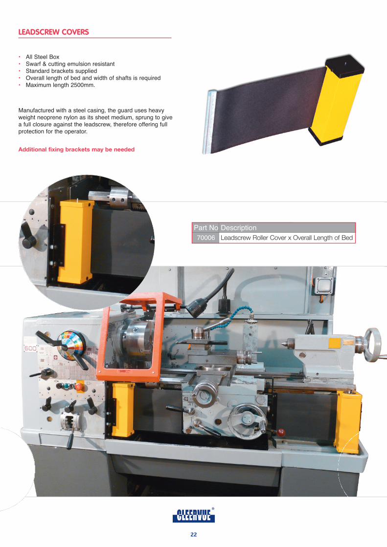
• All Steel Box• Swarf & cutting emulsion resistant• Standard brackets supplied• Overall length of bed and width of shafts is required• Maximum length 2500mm.
Part No Description
70006 Leadscrew Roller Cover x Overall Length of Bed
Manufactured with a steel casing, the guard uses heavyweight neoprene nylon as its sheet medium, sprung to givea full closure against the leadscrew, therefore offering fullprotection for the operator.
additional fixing brackets may be needed
LEADSCREW COVERS
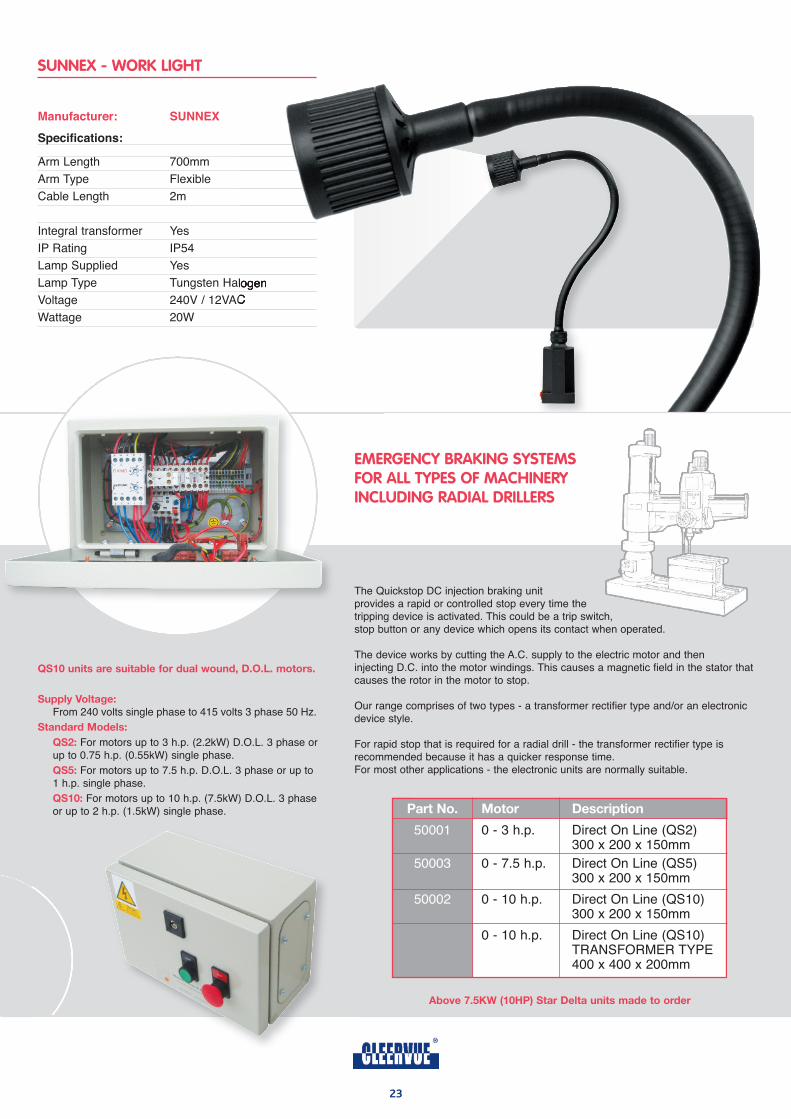
Manufacturer: SunneX
Specifications:
Arm Length 700mm
Arm Type Flexible
Cable Length 2m
Integral transformer Yes
IP Rating IP54
Lamp Supplied Yes
Lamp Type Tungsten Halogen
Voltage 240V / 12VAC
Wattage 20W
SUNNEX - WORK LIGHT
QS10 units are suitable for dual wound, d.o.l. motors.
Supply voltage:
From 240 volts single phase to 415 volts 3 phase 50 Hz.
Standard models:
QS2: For motors up to 3 h.p. (2.2kW) D.O.L. 3 phase orup to 0.75 h.p. (0.55kW) single phase.
QS5: For motors up to 7.5 h.p. D.O.L. 3 phase or up to 1 h.p. single phase.
QS10: For motors up to 10 h.p. (7.5kW) D.O.L. 3 phaseor up to 2 h.p. (1.5kW) single phase.
above 7.5kW (10hp) Star delta units made to order
The Quickstop DC injection braking unit provides a rapid or controlled stop every time thetripping device is activated. This could be a trip switch,stop button or any device which opens its contact when operated.
The device works by cutting the A.C. supply to the electric motor and then injecting D.C. into the motor windings. This causes a magnetic field in the stator thatcauses the rotor in the motor to stop.
Our range comprises of two types - a transformer rectifier type and/or an electronicdevice style.
For rapid stop that is required for a radial drill - the transformer rectifier type is recommended because it has a quicker response time. For most other applications - the electronic units are normally suitable.
EMERGENCY BRAKING SYSTEMS FOR ALL TYPES OF MACHINERY INCLUDING RADIAL DRILLERS
23
part no. motor description
50001 0 - 3 h.p. Direct On Line (QS2)300 x 200 x 150mm
50003 0 - 7.5 h.p. Direct On Line (QS5)300 x 200 x 150mm
50002 0 - 10 h.p. Direct On Line (QS10)300 x 200 x 150mm
0 - 10 h.p. Direct On Line (QS10)TRANSFORMER TYPE400 x 400 x 200mm
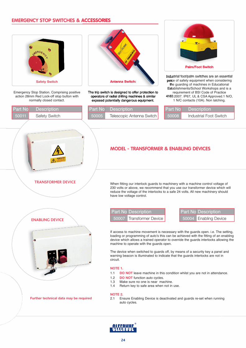
EMERGENCY STOP SWITCHES & ACCESSORIES
MODEL - TRANSFORMER & ENABLING DEVICES
When fitting our interlock guards to machinery with a machine control voltage of 230 volts or above, we recommend that you use our transformer device which willreduce the voltage of the interlocks to a safe 24 volts. All new machinery shouldhave low voltage control.
Part No Description
50007 Transformer Device
TRANSFORMER DEVICE
ENABLING DEVICE
Part No Description
50004 Enabling Device
further technical data may be required
Safety Switch
Emergency Stop Station. Comprising positiveaction 28mm Red Lock-off stop button with
normally closed contact.
Part No Description
50008 Industrial Foot Switch
antenna Switch:
The trip switch is designed to offer protection tooperators of radial drilling machines & similarexposed potentially dangerous equipment.
Part No Description
50011 Safety Switch
palm/foot Switch
Industrial foot/palm switches are an essentialpeice of safety equipment when considering
the guarding of machines in EducationalEstablishments/School Workshops and is a
requirement of BSI Code of Practice4163:2007. IP67, UL & CSA Approved.1 N/O,
1 N/C contacts (10A). Non latching.
Part No Description
50005 Telescopic Antenna Switch
24
If access to machine movement is necessary with the guards open. i.e. The setting, loading or programming of auto’s this can be achieved with the fitting of an enablingdevice which allows a trained operator to override the guards interlocks allowing themachine to operate with the guards open.
The device when switched to guards off, by means of a security key a panel and warning beacon is illuminated to indicate that the guards interlocks are not in circuit.
noTe 1.
1.1 do noT leave machine in this condition whilst you are not in attendance.
1.2 do noT function auto cycles.1.3 Make sure no one is near machine.1.4 Return key to safe area when not in use.
noTe 2.
2.1 Ensure Enabling Device is deactivated and guards re-set when running auto cycles.
25
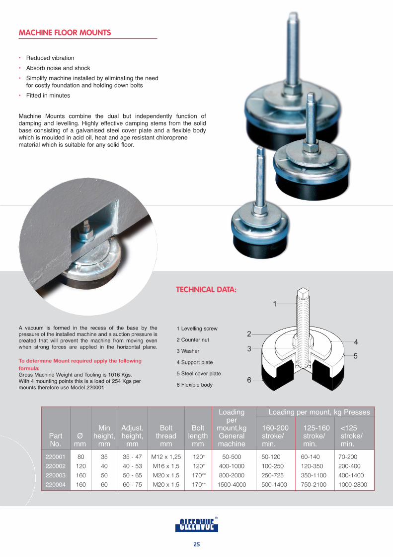
MACHINE FLOOR MOUNTS
• Reduced vibration
• Absorb noise and shock
• Simplify machine installed by eliminating the needfor costly foundation and holding down bolts
• Fitted in minutes
Machine Mounts combine the dual but independently function of damping and levelling. Highly effective damping stems from the solidbase consisting of a galvanised steel cover plate and a flexible bodywhich is moulded in acid oil, heat and age resistant chloroprene material which is suitable for any solid floor.
A vacuum is formed in the recess of the base by the pressure of the installed machine and a suction pressure iscreated that will prevent the machine from moving evenwhen strong forces are applied in the horizontal plane.
To determine mount required apply the following
formula:
Gross Machine Weight and Tooling is 1016 Kgs. With 4 mounting points this is a load of 254 Kgs permounts therefore use Model 220001.
1 Levelling screw
2 Counter nut
3 Washer
4 Support plate
5 Steel cover plate
6 Flexible body
TECHNICAL DATA:
Loading Loading per mount, kg Pressesper
Min Adjust. Bolt Bolt mount,kg 160-200 125-160 <125Part ø height, height, thread length General stroke/ stroke/ stroke/No. mm mm mm mm mm machine min. min. min.
220001 80 35 35 - 47 M12 x 1,25 120* 50-500 50-120 60-140 70-200
220002 120 40 40 - 53 M16 x 1,5 120* 400-1000 100-250 120-350 200-400
220003 160 50 50 - 65 M20 x 1,5 170** 800-2000 250-725 350-1100 400-1400
220004 160 60 60 - 75 M20 x 1,5 170** 1500-4000 500-1400 750-2100 1000-2800
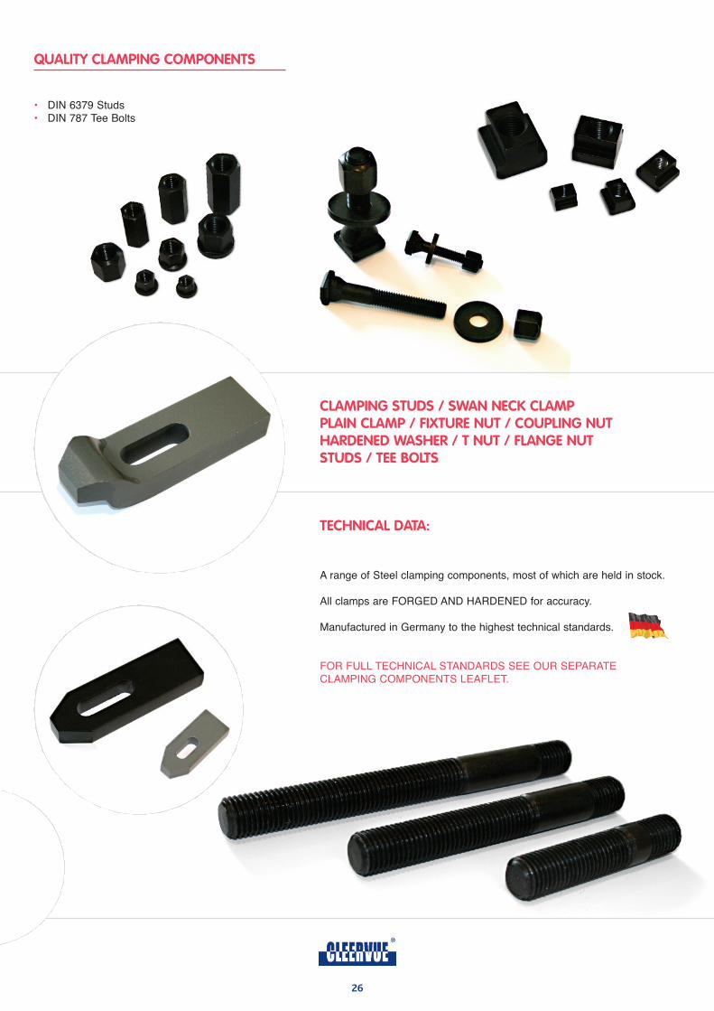
QUALITY CLAMPING COMPONENTS
CLAMPING STUDS / SWAN NECK CLAMPPLAIN CLAMP / FIXTURE NUT / COUPLING NUTHARDENED WASHER / T NUT / FLANGE NUTSTUDS / TEE BOLTS
TECHNICAL DATA:
A range of Steel clamping components, most of which are held in stock.
All clamps are FORGED AND HARDENED for accuracy.
Manufactured in Germany to the highest technical standards.
FOR FULL TECHNICAL STANDARDS SEE OUR SEPARATE CLAMPING COMPONENTS LEAFLET.
• DIN 6379 Studs• DIN 787 Tee Bolts
26
27
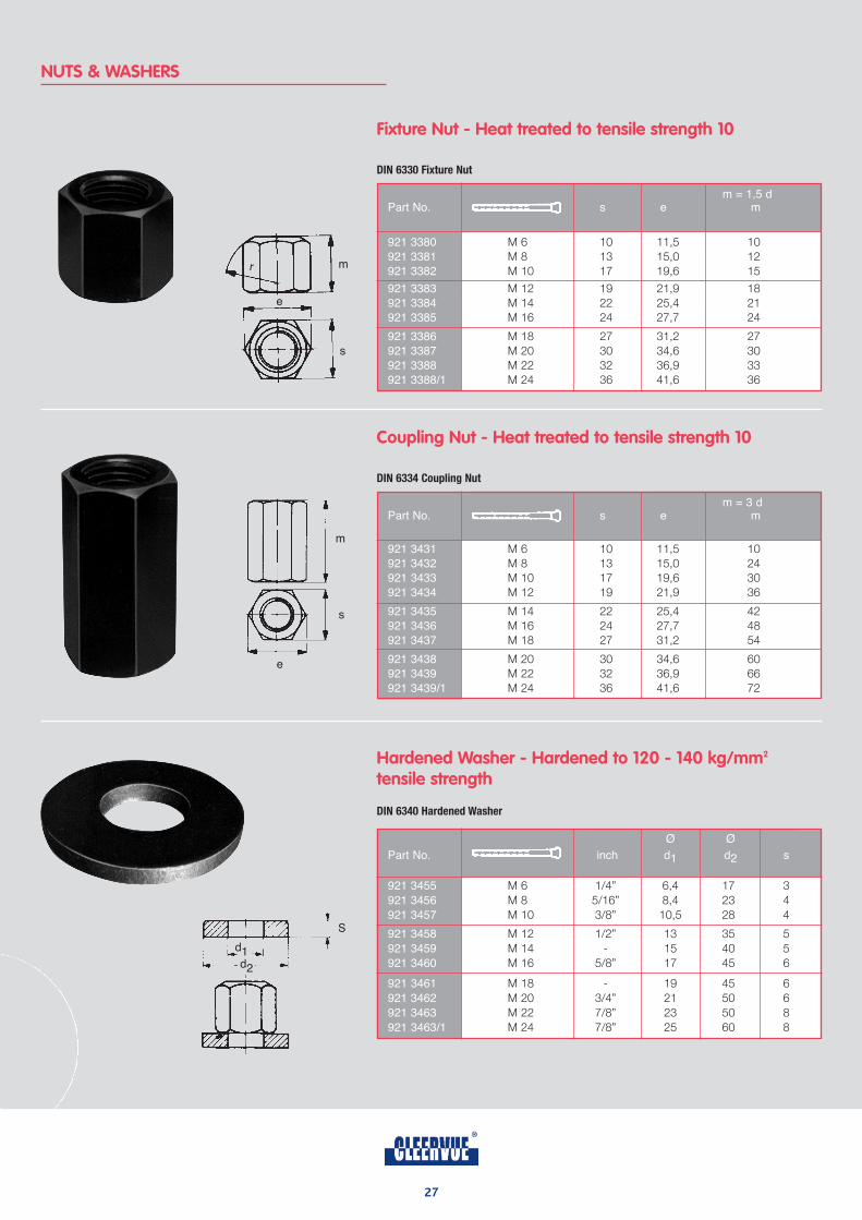
NUTS & WASHERS
Fixture Nut - Heat treated to tensile strength 10
DIN 6330 Fixture Nut
Coupling Nut - Heat treated to tensile strength 10
DIN 6334 Coupling Nut
Hardened Washer - Hardened to 120 - 140 kg/mm2
tensile strength
DIN 6340 Hardened Washer
m = 1,5 dPart No. s e m
921 3380 M 6 10 11,5 10
921 3381 M 8 13 15,0 12
921 3382 M 10 17 19,6 15
921 3383 M 12 19 21,9 18
921 3384 M 14 22 25,4 21
921 3385 M 16 24 27,7 24
921 3386 M 18 27 31,2 27
921 3387 M 20 30 34,6 30
921 3388 M 22 32 36,9 33
921 3388/1 M 24 36 41,6 36
m = 3 dPart No. s e m
921 3431 M 6 10 11,5 10
921 3432 M 8 13 15,0 24
921 3433 M 10 17 19,6 30
921 3434 M 12 19 21,9 36
921 3435 M 14 22 25,4 42
921 3436 M 16 24 27,7 48
921 3437 M 18 27 31,2 54
921 3438 M 20 30 34,6 60
921 3439 M 22 32 36,9 66
921 3439/1 M 24 36 41,6 72
ø ø
Part No. inch d1 d2 s
921 3455 M 6 1/4” 6,4 17 3
921 3456 M 8 5/16” 8,4 23 4
921 3457 M 10 3/8” 10,5 28 4
921 3458 M 12 1/2” 13 35 5
921 3459 M 14 - 15 40 5
921 3460 M 16 5/8” 17 45 6
921 3461 M 18 - 19 45 6
921 3462 M 20 3/4” 21 50 6
921 3463 M 22 7/8” 23 50 8
921 3463/1 M 24 7/8” 25 60 8
m
e
r
s
m
e
s
d1d2
S
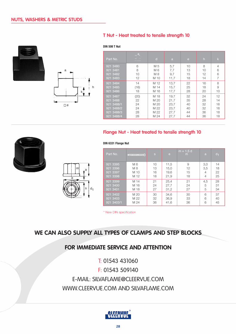
NUTS, WASHERS & METRIC STUDS
WE CAN ALSO SUPPLY ALL TYPES OF CLAMPS AND STEP BLOCKS
FOR IMMEDIATE SERVICE AND ATTENTION
T Nut - Heat treated to tensile strength 10
DIN 508 T Nut
Flange Nut - Heat treated to tensile strength 10
DIN 6331 Flange Nut
a
Part No. d a e h k
921 3480 6 M 5 5,7 10 8 4
921 3481 8 M 6 7,7 13 10 6
921 3482 10 M 8 9,7 15 12 6
921 3483 12 M 10 11,7 18 14 7
921 3484 14 M 12 13,7 22 16 8
921 3485 (16) M 14 15,7 25 18 9
921 3486 18 M 16 17,7 28 20 10
921 3487 (20) M 18 19,7 32 24 12
921 3488 22 M 20 21,7 35 28 14
921 3488/1 24 M 20 23,7 40 32 16
921 3488/2 24 M 22 23,7 40 32 16
921 3488/3 28 M 22 27,7 44 36 18
921 3488/4 28 M 24 27,7 44 36 18
m = 1,5 dPart No. s e m a d1
921 3395 M 6 10 11,5 9 3,0 14
921 3396 M 8 13 15,0 12 3,5 18
921 3397 M 10 16 19,6 15 4 22
921 3398 M 12 18 21,9 18 4 25
921 3399 M 14 21 25,4 21 4,5 28
921 3400 M 16 24 27,7 24 5 31
921 3401 M 18 27 31,2 27 5 34
921 3402 M 20 30 34,6 30 6 37
921 3403 M 22 32 36,9 33 6 40
921 3403/1 M 24 36 41,6 36 6 45
m a
e
s d1
* New DIN specification
a
e
k
h
T: 01543 431060
F: 01543 509140
E-MAIL: [email protected]
WWW.CLEERVUE.COM AND SILVAFLAME.COM
28
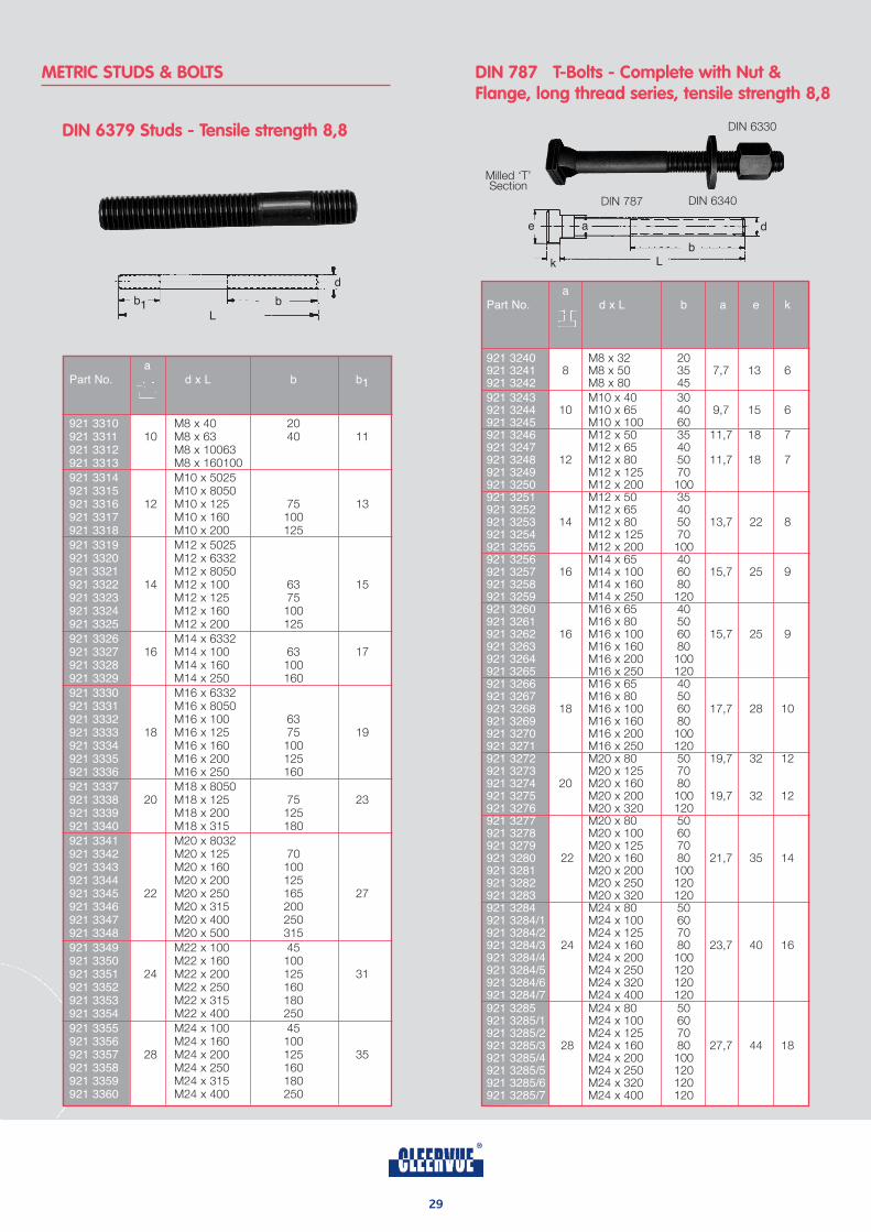
METRIC STUDS & BOLTS
DIN 6379 Studs - Tensile strength 8,8
DIN 787 T-Bolts - Complete with Nut &Flange, long thread series, tensile strength 8,8
aPart No. d x L b a e k
921 3240 M8 x 32 20921 3241 8 M8 x 50 35 7,7 13 6921 3242 M8 x 80 45
921 3243 M10 x 40 30921 3244 10 M10 x 65 40 9,7 15 6921 3245 M10 x 100 60921 3246 M12 x 50 35 11,7 18 7921 3247 M12 x 65 40921 3248 12 M12 x 80 50 11,7 18 7921 3249 M12 x 125 70921 3250 M12 x 200 100921 3251 M12 x 50 35921 3252 M12 x 65 40921 3253 14 M12 x 80 50 13,7 22 8921 3254 M12 x 125 70921 3255 M12 x 200 100921 3256 M14 x 65 40921 3257 16 M14 x 100 60 15,7 25 9921 3258 M14 x 160 80921 3259 M14 x 250 120921 3260 M16 x 65 40921 3261 M16 x 80 50921 3262 16 M16 x 100 60 15,7 25 9921 3263 M16 x 160 80921 3264 M16 x 200 100921 3265 M16 x 250 120921 3266 M16 x 65 40921 3267 M16 x 80 50921 3268 18 M16 x 100 60 17,7 28 10921 3269 M16 x 160 80921 3270 M16 x 200 100921 3271 M16 x 250 120921 3272 M20 x 80 50 19,7 32 12921 3273 M20 x 125 70921 3274 20 M20 x 160 80921 3275 M20 x 200 100 19,7 32 12921 3276 M20 x 320 120921 3277 M20 x 80 50921 3278 M20 x 100 60921 3279 M20 x 125 70921 3280 22 M20 x 160 80 21,7 35 14921 3281 M20 x 200 100921 3282 M20 x 250 120921 3283 M20 x 320 120921 3284 M24 x 80 50921 3284/1 M24 x 100 60921 3284/2 M24 x 125 70921 3284/3 24 M24 x 160 80 23,7 40 16921 3284/4 M24 x 200 100921 3284/5 M24 x 250 120921 3284/6 M24 x 320 120921 3284/7 M24 x 400 120921 3285 M24 x 80 50921 3285/1 M24 x 100 60921 3285/2 M24 x 125 70921 3285/3 28 M24 x 160 80 27,7 44 18921 3285/4 M24 x 200 100921 3285/5 M24 x 250 120921 3285/6 M24 x 320 120921 3285/7 M24 x 400 120
L
b1 b
d
Milled ‘T’Section
DIN 787 DIN 6340
DIN 6330
e
k
a
Lb
d
29
aPart No. d x L b b1
921 3310 M8 x 40 20921 3311 10 M8 x 63 40 11921 3312 M8 x 10063921 3313 M8 x 160100
921 3314 M10 x 5025921 3315 M10 x 8050921 3316 12 M10 x 125 75 13921 3317 M10 x 160 100921 3318 M10 x 200 125
921 3319 M12 x 5025921 3320 M12 x 6332921 3321 M12 x 8050921 3322 14 M12 x 100 63 15921 3323 M12 x 125 75921 3324 M12 x 160 100921 3325 M12 x 200 125
921 3326 M14 x 6332921 3327 16 M14 x 100 63 17921 3328 M14 x 160 100921 3329 M14 x 250 160
921 3330 M16 x 6332921 3331 M16 x 8050921 3332 M16 x 100 63921 3333 18 M16 x 125 75 19921 3334 M16 x 160 100921 3335 M16 x 200 125921 3336 M16 x 250 160
921 3337 M18 x 8050921 3338 20 M18 x 125 75 23921 3339 M18 x 200 125921 3340 M18 x 315 180
921 3341 M20 x 8032921 3342 M20 x 125 70921 3343 M20 x 160 100921 3344 M20 x 200 125921 3345 22 M20 x 250 165 27921 3346 M20 x 315 200921 3347 M20 x 400 250921 3348 M20 x 500 315
921 3349 M22 x 100 45921 3350 M22 x 160 100921 3351 24 M22 x 200 125 31921 3352 M22 x 250 160921 3353 M22 x 315 180921 3354 M22 x 400 250
921 3355 M24 x 100 45921 3356 M24 x 160 100921 3357 28 M24 x 200 125 35921 3358 M24 x 250 160921 3359 M24 x 315 180921 3360 M24 x 400 250
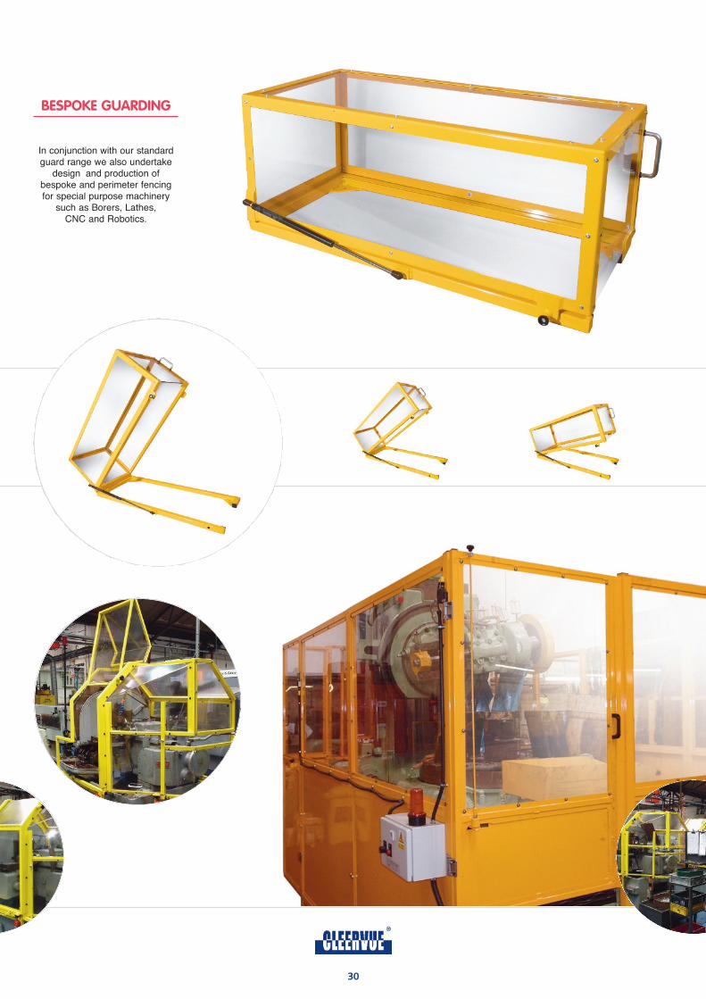
BESPOKE GUARDING
30
In conjunction with our standardguard range we also undertake
design and production ofbespoke and perimeter fencingfor special purpose machinery
such as Borers, Lathes, CNC and Robotics.
31
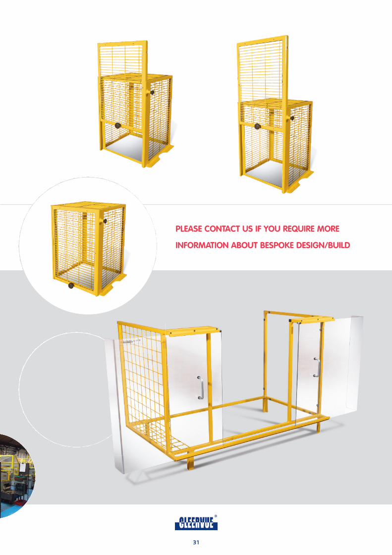
PLEASE CONTACT US IF YOU REQUIRE MORE
INFORMATION ABOUT BESPOKE DESIGN/BUILD
93/1844
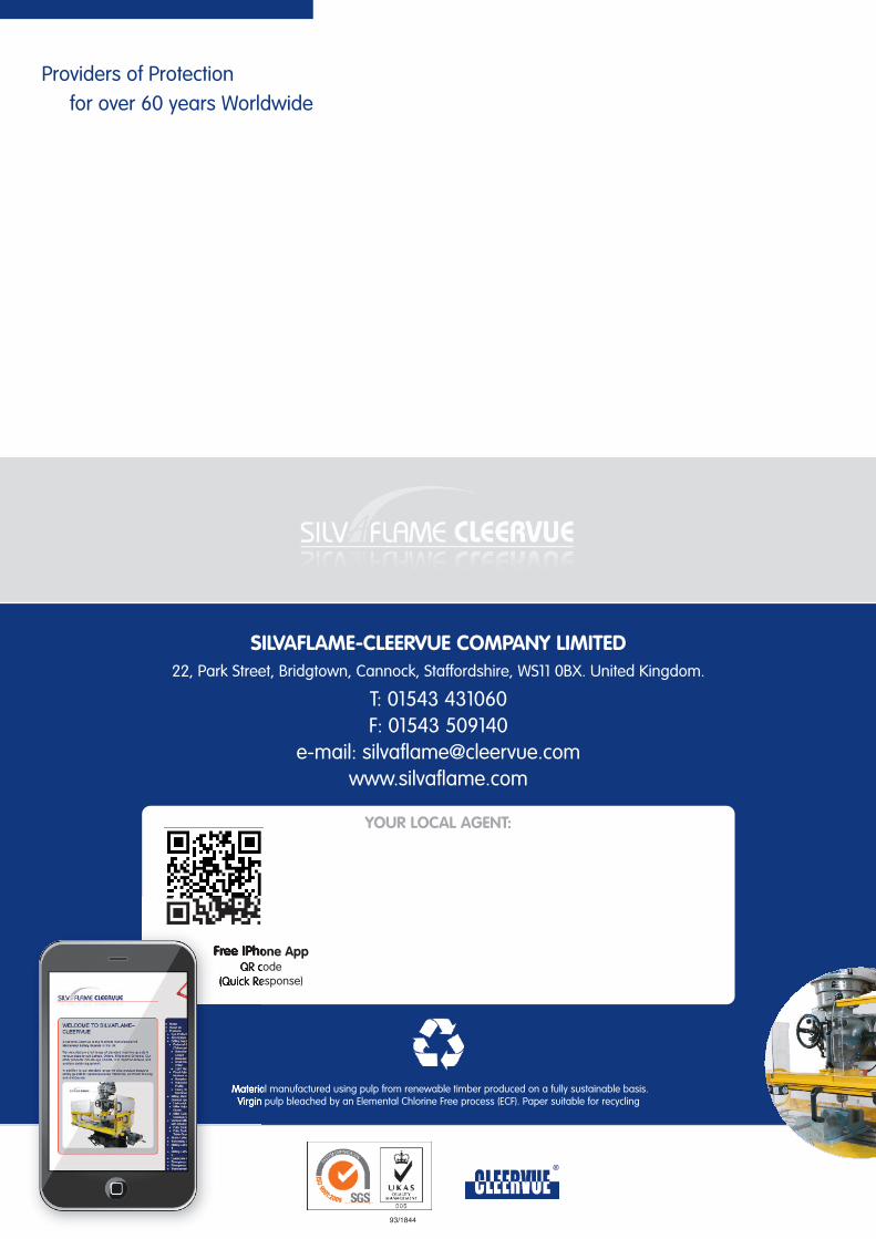
Providers of Protection
for over 60 years Worldwide
SILVAFLAME-CLEERVUE COMPANY LIMITED22, Park Street, Bridgtown, Cannock, Staffordshire, WS11 0BX. United Kingdom.
T: 01543 431060F: 01543 509140
e-mail: [email protected]
YOUR LOCAL AGENT:
Material manufactured using pulp from renewable timber produced on a fully sustainable basis.Virgin pulp bleached by an Elemental Chlorine Free process (ECF). Paper suitable for recycling
Free IPhone AppQR code
(Quick Response)


