Embed Size (px)
DESCRIPTION
SDI monitor manual
Citation preview

EZ SDI-1TM
Installation and
Operating Manual
® 2450 Business Park Dr. Vista, CA 92081 (760) 727-3711 (760) 727-4427 www.appliedmembranes.com [email protected]
Distributed By:

Manual Revisions i
EZ SDI-1
TM Automated
Silt Density Index Test System
Installation and Operating Manual Copyright 2014 NOTICE This manual is protected by federal copyright laws. It should not be copied in any way, shape, or fashion without written permission. Version 3.06
® 2450 Business Park Dr. Vista, CA 92081 (760) 727-3711 (760) 727-4427 www.appliedmembranes.com [email protected]
Distributed By:

Version Log
Version Date Effective Pages Description of Changes
3.00 03/12/02 - Original Issue
3.01 04/09/02 3-5 Heading correction
3.02 04/09/02 - Corrected Typographical Errors
3.03 09/03/02 - Added Filter Options
3.04 02/04/03 Appendix A Analog Output
3.05 11/21/03 1-1, 2-1, 2-2, 3-3, 3-5, 3-6, 3-7, section 4, section 5
Clarified Specifications, Added Calibration, Updated Troubleshooting guide
3.06 04/30/14 - Removed Filter Options
® 2450 Business Park Dr. Vista, CA 92081 (760) 727-3711 (760) 727-4427 www.appliedmembranes.com [email protected]
Distributed By:

Conventions and Symbols ii Special characters, listed and described below, are used in this documentation to emphasize certain information.
Note: Emphasizes additional information pertinent to the subject matter.
Warning: Emphasizes information about actions, which may result in personal injury.
Caution: Emphasizes information about actions, which may result in equipment damage.
The following electrical symbols may be used in this documentation. Symbol Meaning Direct current. Alternating current. Both direct and alternating current. Earth (ground) terminal. Frame or chassis terminal.
!
® 2450 Business Park Dr. Vista, CA 92081 (760) 727-3711 (760) 727-4427 www.appliedmembranes.com [email protected]
Distributed By:
General Limited Warranty iii
1. In no event will manufacturer., or any of its representatives, be responsible or liable for indirect or consequential damages resulting from the use or application of any product. The user and those responsible for applying the product must satisfy themselves with the acceptability of the application.
2. Manufacturer extends a one (1) year warranty covering parts and labor on any factory manufactured product. Any product, which is found to have a defect in workmanship or components, shall be replaced or repaired at the option of the manufacturer.
3. A prepaid minimum inspection fee is required for the repair of products not covered by the warranty period. Contact your representative for repair information and repair rates.
4. The manufacturer will not be responsible for replacement or repair of any product that was damaged by improper installation, mishandling, or user modifications.
5. All units returned for repair must have a RA (return authorization) number obtained from the manufacturer. This RA number must be included with the returned product and any correspondence regarding the returned product must reference that number. Shipping on all returned products must be pre-paid and insured. Manufacturer will not be responsible for any shipping damage incurred. Repaired products will be shipped pre-paid and insured.
6. Manufacturer reserves the right to change any specification or feature of any product at any time. This right also extends to repair fees or any warranty conditions contained herein.
Warranty
® 2450 Business Park Dr. Vista, CA 92081 (760) 727-3711 (760) 727-4427 www.appliedmembranes.com [email protected]
Distributed By:

Table of Contents iv EZ SDITM Overview 1
Introduction 1-1 Features 1-1 Specifications 1-1 Alarm Outputs 1-2 Operation 1-2 Controls 1-2
Installation 2
Environmental 2-1 Mounting 2-1 Connections 2-1 Ground 2-2 Water 2-2 Alarm Outputs 2-2
Wiring Diagram 2-3 Operation 3
Controls 3-1 Keypad 3-1 LED Indicators 3-2 Test Triggers 3-2 Filter Cartridges 3-2 Test Procedure 3.3 Sequence 3-3 Screens 3-3 Settings 3-5 Settings Table 3-5 Data Logging & SDI Data Reader 3-7 Screen Operation 3-8 Calibration 4 Pressure 4-1 Temperature 4-2 Calibration Troubleshooting 4-3 Troubleshooting 5 Appendix A Analog Output Option A-1 Notes
® 2450 Business Park Dr. Vista, CA 92081 (760) 727-3711 (760) 727-4427 www.appliedmembranes.com [email protected]
Distributed By:

EZ SDITM
Overview 1 1
Introduction The EZ SDITM Automated Silt Density Index Test System is designed to perform a standard Silt Density Index Test according to the ASTM D189-95. Information is displayed on a back-lit liquid crystal display, and on individual light-emitting diodes (LED). Functions and controls are operated through switches on the membrane keypad.
Test Start
Test Abort
Drain
Display
TESTING
PRESSURE
VENT
DRAIN
Features The EZ SDITM incorporates the following features:
One Temperature sensor to measure temperature change during test. One Pressure sensor to ensure proper filter feed pressure. Two Alarm Outputs; one for high or low filter feed pressure, and one for high SDI.
Specifications The EZ SDITM incorporates the following specifications:
Power Requirements: The controller requires 120 / 240 volts AC, 50 or 60 Hz, single phase, 1 amp maximum. Flow Requirements: The controller requires a feed stream with the following conditions: 1000 mL / Min. 70 – 1500 PSI Tubing connections: The three tubing connections located at the bottom of the enclosure are as follows: 1 feed water connection: ¼” Tubing 2 vent connections: each are ¼” Tubing Fast & Tite connectors 1 drain connection: ¼” I.D. hose barb. The hose is included in the shipment. The unit will flow 150 mL / Min to the drain at all times when the unit is pressurized. All drain and vent tubing must be routed to an open drain with no restrictions. A
® 2450 Business Park Dr. Vista, CA 92081 (760) 727-3711 (760) 727-4427 www.appliedmembranes.com [email protected]
Distributed By:

valve may be placed on the feed water inlet tubing to prevent excess water flow to waste between tests. NOTE: If the feed water flow to the EZ SDITM is interrupted for extended periods between tests, biogrowth may occur in the sample tubing and affect test results. Environment: The controller can operate at a temperature from 0° to 55° C (32° to 131° F). Relative humidity must not exceed 95 percent.
Alarm Outputs The EZ SDITM is equipped with the following alarm outputs. All outputs are in the form of SPST relays rated at 2 Amps, 250 VAC /30 VDC. Relay # 1: This output is provided as an external alarm indicator. The output is energized when the following alarm conditions are present: Low Pressure Filter Feed Pressure High Pressure Filter Feed Pressure Relay # 2: This output is for external alarm indicators. The output is energized when the following alarm conditions are present: High Silt Density Index
All outputs are dry contact outputs and do not have internal circuit protection. It is the user’s responsibility to provide proper circuit protection on each output.
Operation The EZ SDITM has two operating modes, Test and Standby. These are selected from the keypad. The test mode is the operational mode of the system. After installing a new filter, the system may be placed into the test mode by means of the TEST START key. The system will remain in the test mode until all three SDI tests, SDI5, SDI10 and SDI15, have been completed. The tests may be initiated manually by pressing the TEST Start Key, by a preset timed interval or by an external signal in the form of a dry contact (momentary for at least five seconds). The standby mode is intended to place the system in a temporary non-operational mode. The system will go into the standby mode at the completion of the test or if the test is aborted due to high or low pressure, high SDI value or operator input. After a successful SDI test the unit will display a “RELOAD FILTER” message. The system will stay in standby mode until the operator presses the TEST START key.
Controls The EZ SDITM is equipped with the following controls and indicators on the front panel of
the controller.
4 x 20 LCD with LED Backlight Four LED Indicators for Alarms and Status Four Tactile Keys for Control and Data Entry
1-2
!
® 2450 Business Park Dr. Vista, CA 92081 (760) 727-3711 (760) 727-4427 www.appliedmembranes.com [email protected]
Distributed By:

Installation 2 Environmental The EZ SDITM is mounted onto a flat wall or panel surface. The unit should be mounted
level both front to back and side-to-side. The EZ SDITM should not be used in explosive environments. General environmental specifications are listed below.
Environmental Specifications
Specification Rating
Storage Temperature -20 to 70 Deg C Ambient Operating Temperature 0 to 55 Deg C Ambient Humidity 30% to 95 % Relative Humidity (Non-Condensing)
Mounting When mounting the EZ SDITM, sufficient room should be allowed on the side and bottom
of the device for access to the I/O and sample connections. Mounting dimensions are shown below. Note: Filter changing is easier if the EZ SDITM is mounted at eye level.
Test Start
Test Abort
Drain
Display
TESTING
PRESSURE
VENT
DRAIN
Dimensions to Enclosure Mounting Feet
14.00"
12.5
0"
Connections Screw terminals are provided for making connections for alarm outputs. The terminals
are numbered in ascending order from bottom to top. A power cord is supplied for standard 120VAC plug-in applications. If the supplied power is to be hardwired to the EZ SDITM then the power terminals are located on the 24 VDC power supply. (L, N, G). Power should always be disconnected from the EZ SDITM before making or changing any connections. The EZ SDITM has internal circuit protection on the solenoid valves and sensors in the form of a panel mounted fuse holder. Only ¼” x 1 ¼” fuses rated at 2 amps should be used.
Ground A good common ground reference (earth ground) is essential for proper operation of the
EZ SDITM. A good earth ground or power circuit ground should be connected to the power supply terminal labeled G. If a power cord is used then the ground terminal on the power cord must be grounded.
® 2450 Business Park Dr. Vista, CA 92081 (760) 727-3711 (760) 727-4427 www.appliedmembranes.com [email protected]
Distributed By:
Process Piping
120 / 240 VAC60 / 50 Hz, 1 A
Open Drain1/4" TubingStainless Steel
70 - 1500 PSI1000 mL / Min
Test Start
Test Abort
Drain
Display
TESTING
PRESSURE
VENT
DRAIN
Air VentWater VentDrain
Feed Connection
DrainWater VentAir Vent
1/4" NPTSS Connector
Parker Fast & Tite1/4" Tubing Connectors 1/4" I.D. Tubing
Hose Barb
Inline Screen
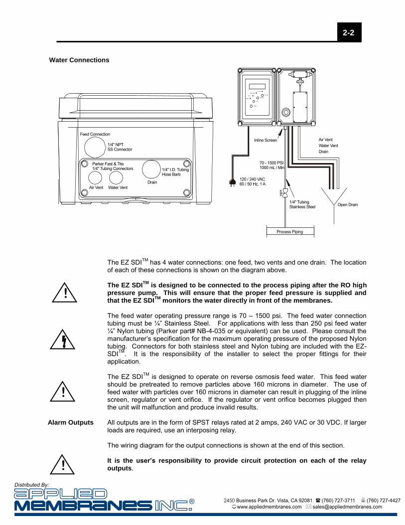
The EZ SDITM has 4 water connections: one feed, two vents and one drain. The location
of each of these connections is shown on the diagram above. The EZ SDI
TM is designed to be connected to the process piping after the RO high
pressure pump. This will ensure that the proper feed pressure is supplied and that the EZ SDI
TM monitors the water directly in front of the membranes.
The feed water operating pressure range is 70 – 1500 psi. The feed water connection tubing must be ¼” Stainless Steel. For applications with less than 250 psi feed water ¼” Nylon tubing (Parker part# NB-4-035 or equivalent) can be used. Please consult the manufacturer’s specification for the maximum operating pressure of the proposed Nylon tubing. Connectors for both stainless steel and Nylon tubing are included with the EZ-SDITM. It is the responsibility of the installer to select the proper fittings for their application. The EZ SDITM is designed to operate on reverse osmosis feed water. This feed water should be pretreated to remove particles above 160 microns in diameter. The use of feed water with particles over 160 microns in diameter can result in plugging of the inline screen, regulator or vent orifice. If the regulator or vent orifice becomes plugged then the unit will malfunction and produce invalid results.
Alarm Outputs All outputs are in the form of SPST relays rated at 2 amps, 240 VAC or 30 VDC. If larger
loads are required, use an interposing relay. The wiring diagram for the output connections is shown at the end of this section.
It is the user’s responsibility to provide circuit protection on each of the relay outputs.
2-2
!
!
Water Connections
!
® 2450 Business Park Dr. Vista, CA 92081 (760) 727-3711 (760) 727-4427 www.appliedmembranes.com [email protected]
Distributed By:

Power SupplyFurnished by User
!
User must supplycircuit protectionfor relay outputs.Relays rated as follows for inductive load:
2A, 250 VAC2A, 30 VDC
PressureAlarm
SDIAlarm
1009
0605
0403
02Relay 1
01
2827
RTD
RTD
Relay 2
Relay 3
Relay 3
Relay 4
Relay 4
3029
+ 24
V
Sign
alPr
essu
reSe
nsor
Level Sensor
L
N
V-
V+G
24 Volt Power Supply
Red
White
Black
Tem
pera
ture
Sen
sor
Panel MountFuse Holder
Feed 1
Vent
Drain
1211
Relay 5
Relay 5
0807
1413
1615
Relay 6
Relay 6
Relay 7
Relay 7
Relay 8
Relay 8
2221
2019
18
+ 24 V
17
DC-
Level Switch +
Level Signal
Level Switch -
Input 1
Input 2
Input 3
2423
2625 Input 4
Common
Wire Alarm Outputsas Shown
External Dry ContactUsed for Remote Trigger
Wire External Inputas Shown
Indicates Factory-Wired ComponentsDO NOT DISCONNECT OR ALTER!
This is an example-wiring diagram for the relay alarm outputs and remote trigger input. DO NOT DISCONNECT OR ALTER ANY FACTORY WIRING, AS THIS WILL CAUSE THE UNIT TO MALFUNCTION.
2-3
® 2450 Business Park Dr. Vista, CA 92081 (760) 727-3711 (760) 727-4427 www.appliedmembranes.com [email protected]
Distributed By:

Operation 3 Controls The EZ SDITM is housed in a NEMA 4X enclosure with a membrane keypad. Indicators
include a 4 line x 20 character LCD with LED backlight and four LED indicators for alarm conditions. The major components of the EZ SDITM are illustrated below.
Test Start
Test Abort
Drain
Display
TESTING
PRESSURE
VENT
DRAIN
Volumetric Container
FilterCartridge
PressureRegulator
LCD Display
LED Indicators
Control Keys
FeedManifold
Keypad The membrane keypad contains 4 tactile keys that are used for a number of control and
data entry functions.
Test Start: Pressing this key places the unit in test mode. Depending upon the activation method, a test may start immediately or the unit may display a “Waiting For Trigger “message. This key is also used as a “down arrow” when one of the Settings Screens is displayed. In the settings screens it is used to decrease the current value of the parameter displayed. Test Abort: Pressing this key aborts the test in progress. To reset the unit to the standby position perform a Master Reset (see Test Procedure, page 3-3.) A Master Reset can be performed at anytime during the programmed test mode. This key is also used as an “up arrow” when one of the Settings Screens is displayed. In the settings screens it is used to increase the current value of the parameter displayed. Drain: Pressing this key opens the volumetric chamber drain in the Standby mode. This key is also used as an Enter key when one of the Settings Screens is displayed. Display: Pressing this key advances the display screen to the next screen. To access the setting screens press and hold this key for 5 seconds. This key is also used when entering the security code in the settings screens. Press the Display key to move to the next digit position when entering the access code.
LED Indicators The four LED indicators are used to indicate status and alarm conditions.
® 2450 Business Park Dr. Vista, CA 92081 (760) 727-3711 (760) 727-4427 www.appliedmembranes.com [email protected]
Distributed By:

TESTING: A blinking Testing LED indicates that the SDI test is in progress. Once the SDI test has been completed, or if the test is aborted for any reason, the Testing indicator will be continuously illuminated. PRESSURE: A blinking pressure LED indicates that the pressure is above the high pressure warning set point or below the low pressure warning set point. VENT: Indicates that the test chamber air vent is open. DRAIN: Indicates that the volumetric container drain is open.
Test Triggers The SDI test may be triggered by one of three means. These are configured in the Settings screens and are described below.
MANUAL: In this mode, the filter test is initiated by pressing the TEST START key. After the test is completed, the first line of the display will show “RELOAD FILTER”. REMOTE INPUT: In this mode, the filter test is initiated by a dry contact input from a remote device such as a PLC or turbidity meter. The number of input contact closures to initiate the test is adjustable from the Settings screens. For example, the system may be configured to initiate the filter test every five times the contacts close. This may be useful when triggering tests based upon equipment start and stop cycles, filter backwashes, etc. The Status screen shows the number of input signals (contact closures) counted before the initiation of the test. The remote contact input must remain closed for five seconds to be detected. After replacing the filter, the TEST START key must be pressed to place the unit in test mode. The unit will wait for the input trigger before performing the test. After the test is completed, the first line of the display will show “RELOAD FILTER”. TIMER: The timer trigger works in a similar fashion as the Remote Input trigger. After replacing the filter cartridge, pressing the TEST START key initiates the interval timer (configured in minutes from the Settings screens). At the expiration of this timer the test is initiated. After the test is completed, the first line of the display will show “RELOAD FILTER”.
Filter Cartridges The EZ SDITM uses a disposable 25 mm cartridge. To change the disposable cartridge, simply remove the old cartridge by un-twisting the cartridge from the Luer fitting on the underside of the feed manifold. Re-install the new cartridge by twisting ¾ turn on to the Luer fitting. Do not over-tighten!
3-2
25mm DisposableCartridge
Make sure that filter tubedirects filtrate to volumetric chamber.
EZ SDI Filter Cartridges
® 2450 Business Park Dr. Vista, CA 92081 (760) 727-3711 (760) 727-4427 www.appliedmembranes.com [email protected]
Distributed By:

Test Procedure
1. If necessary, perform a Master Reset by first pressing the TEST ABORT key. While holding it down, press the DRAIN key. Release the TEST ABORT key and then release the DRAIN key. On the main screen, the first line of the display will change to “RELOAD FILTERS”.
2. Unscrew and remove previously used filter cartridge from the feed manifold.
3. Replace the filter cartridge by inserting the female end of the Luer connection on the cartridge into the fitting under the feed manifold. Twist the cartridge to ensure a tight seal but do not over tighten! A ¾ turn is sufficient.
4. If a valve has been installed in the feed source tubing, make sure that valve is open.
5. Adjust the pressure regulator until the pressure displayed on the LCD display reads 30 psi. NOTE: In low-pressure applications it might be necessary to adjust the pressure reading to slightly above 30 psi in order to maintain 30 psi during the test.
6. Check the water vent drain tubing to ensure a continuous flow is present. NOTE: If a continuous flow is not present then the tubing may have some blockage. The blockage must be removed before starting the test.
7. Press the TEST START key to begin the test sequence. Depending upon the type of trigger selected, the EZ SDITM
may start testing immediately or the system will wait for the appropriate trigger.
8. The LCD will display “TESTING”, the Test LED will blink and the testing will begin.
9. If at any time during the test the system automatically aborts the test, look at the main screen to determine the cause. Refer to the troubleshooting section of this manual to review possible solutions.
Sequence The normal testing sequence is listed below. This sequence is initiated when the
appropriate trigger is activated. The test will not be interrupted unless the TEST ABORT key is pressed, an alarm occurs or the test is completed. Start Test Open Drain Valve wait 8 seconds. Close Drain Valve and open both Vent and Feed Valves wait 2 seconds. Close Vent Valve When volumetric container is full then open the Drain Valve. Wait for 300 seconds then close Drain Valve. When volumetric container is full then open the Drain Valve. Wait for 300 seconds then close Drain Valve When volumetric container is full then open the Drain Valve. Wait for 300 seconds then close Drain Valve When volumetric container is full then open the Drain Valve. Test Complete Note: If the change in temperature during a test is greater than 1.0oC the results should be discarded. For each degree of temperature change the flow through the filter changes approximately 3%.
Screens The EZ SDITM displays data and operating status by means of a number of screens displayed on the LCD. Specialized screens are also used for entering set points. The following page contains an illustration of the screen displayed by the EZ SDITM and instructions on how to maneuver through the settings screens.
3-3
® 2450 Business Park Dr. Vista, CA 92081 (760) 727-3711 (760) 727-4427 www.appliedmembranes.com [email protected]
Distributed By:

Main Screen - The Main Screen displays information regarding the current test and calculated SDI values. The top line indicates the current system status. The next two lines display the last calculated SDI value for SDI5, SDI10 and SDI15. The last line shows the current filter feed pressure and the change in temperature during the last test.
>1< RELOAD FILTERSSDI5 SDI10 SDI1500.0 00.0 00.0PRESS=30 dT=0.5
Current PressureTemperature Change
System Status
SDI Value
Status Screen - The Status Screen displays information regarding the system status. The top line indicates the current time and date. The next two lines display the archive screen location on which the current test results will be saved. They also display the current and remaining number of input triggers before the test will begin. The last line shows the current test initiation mode and the current temperature.
RT-10:11:36 02/10/02TEST=1 TRG=0/1TIMER START=0/5MODE-TIMER T=13.5
Remote Input Status and Setting
Current Time and Date
Timer Elapsed Time and Setting
Current Temperature
Archive Screen #
Current TriggerMode
Archive Screen - The 4 Archive Screens display information regarding the previous 4 tests. The top line indicates whether the test passed or failed due to pressure and the change in temperature during the test. The next line displays the time and date that the archived test was started. The last two lines display the SDI Values for the archived test.
LOG[1] dT=0.5 >PASS<16:04:05 02/07/02SDI5 SDI10 SDI156.55 4.35 3.21
Indicates if TestPassed or Failed
Time and Date Test Was Started
SDI Values for Archived Test
Change in Temp.during Test
Archive ScreenNumber
3-4
® 2450 Business Park Dr. Vista, CA 92081 (760) 727-3711 (760) 727-4427 www.appliedmembranes.com [email protected]
Distributed By:

Settings Settings screens - in the EZ SDITM are accessed by pressing and holding the Display
key for five seconds. The user will be required to enter a four-digit access code to use the Settings screens. See the following page for instructions on entering the access code (default code is 1111). Upon entering the Settings data entry screens, the user may scroll through the settings by repeatedly pressing the Display key. Once in the Settings screens, the user may return to the Data screens by pressing the Display key for six seconds.
Settings may be changed only when the system is in Standby. Settings Table The table below lists all of the settings that may be changed in the EZ SDITM. Each
setting is identified with an index number.
EZ SDITM
Settings
Index Abbreviation Full Name Format Details
0 Test Interval (min) Interval Between Tests in Timer Trigger Mode
00
Enter the number of minutes desired before the filter test starts, when in timer trigger mode.
1 Trigger 0=M 1=I 2=T Trigger Mode 0
Use this setting to select the trigger mode. Enter 0 for Manual, 1 for Remote Input, 2 for Timer
2 Trigger Counter Trigger Counter 00
Enter the number of times the remote input must contact in order to start the next filter test. Used only in Remote Input trigger mode.
3 Clock Hrs Clock Hours 00 Enter current clock hours 0-23.
4 Clock Min Clock Minutes 00 Enter current clock minutes 0-59.
5 Clock Sec Clock Seconds 00 Enter clock seconds 0-59.
6 Clock Month Clock Month 00 Enter clock month 1-12.
7 Clock Date Clock Date 00 Enter clock date 1-31.
8 Clock Year Clock Year 00 Enter clock year (i.e., 02).
9 Temp Zero Temperature Zero Calibration 000
Enter the “Raw” analog value as measured by the temperature sensor for zero degrees Celsius. The sensor must be placed in water that is 0oC.
10 Temp Factor Temperature Calibration Factor
0000
Adjust the temperature factor up or down using the keypad until the “Act” temperature value matches the temperature of the water the sensor is in.
11 Pressure Zero Pressure Zero Calibration 000
Enter the “Raw” analog value as measured by the pressure transmitter for zero PSI. The pressure transmitter must have 0 psig applied.
!
3-5
® 2450 Business Park Dr. Vista, CA 92081 (760) 727-3711 (760) 727-4427 www.appliedmembranes.com [email protected]
Distributed By:
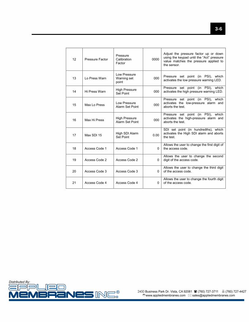
12 Pressure Factor Pressure Calibration Factor
0000
Adjust the pressure factor up or down using the keypad until the “Act” pressure value matches the pressure applied to the sensor.
13 Lo Press Warn Low Pressure Warning set point
000
Pressure set point (in PSI), which activates the low pressure warning LED.
14 Hi Press Warn High Pressure Set Point 000
Pressure set point (in PSI), which activates the high pressure warning LED.
15 Max Lo Press Low Pressure Alarm Set Point 000
Pressure set point (in PSI), which activates the low-pressure alarm and aborts the test.
16 Max Hi Press High Pressure Alarm Set Point 000
Pressure set point (in PSI), which activates the high-pressure alarm and aborts the test.
17 Max SDI 15 High SDI Alarm Set Point 0.00
SDI set point (in hundredths), which activates the High SDI alarm and aborts the test.
18 Access Code 1 Access Code 1 0 Allows the user to change the first digit of the access code.
19 Access Code 2 Access Code 2 0 Allows the user to change the second digit of the access code.
20 Access Code 3 Access Code 3 0 Allows the user to change the third digit of the access code.
21 Access Code 4 Access Code 4 0 Allows the user to change the fourth digit of the access code.
3-6
® 2450 Business Park Dr. Vista, CA 92081 (760) 727-3711 (760) 727-4427 www.appliedmembranes.com [email protected]
Distributed By:
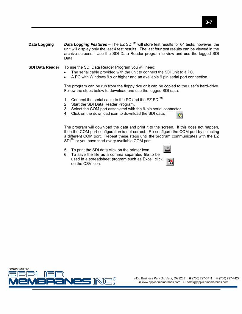
Data Logging Data Logging Features – The EZ SDITM will store test results for 64 tests, however, the
unit will display only the last 4 test results. The last four test results can be viewed in the archive screens. Use the SDI Data Reader program to view and use the logged SDI Data.
SDI Data Reader To use the SDI Data Reader Program you will need: The serial cable provided with the unit to connect the SDI unit to a PC. A PC with Windows 9.x or higher and an available 9 pin serial port connection. The program can be run from the floppy rive or it can be copied to the user’s hard-drive. Follow the steps below to download and use the logged SDI data. 1. Connect the serial cable to the PC and the EZ SDITM 2. Start the SDI Data Reader Program. 3. Select the COM port associated with the 9-pin serial connector. 4. Click on the download icon to download the SDI data. The program will download the data and print it to the screen. If this does not happen, then the COM port configuration is not correct. Re-configure the COM port by selecting a different COM port. Repeat these steps until the program communicates with the EZ SDITM or you have tried every available COM port. 5. To print the SDI data click on the printer icon. 6. To save the file as a comma separated file to be
used in a spreadsheet program such as Excel, click on the CSV icon.
3-7
® 2450 Business Park Dr. Vista, CA 92081 (760) 727-3711 (760) 727-4427 www.appliedmembranes.com [email protected]
Distributed By:

>1< RELOAD FILTERS
SDI5 SDI10 SDI15
00.0 00.0 00.0
PRESS=30 dT=0.5
ACCESS CODE
[Dsp]-Slct [Drn]-Exe
[?][?][?][?]
[^]
Hold
"Disp
lay" f
or S
ix Se
cond
s
Rep
eate
dly
pres
sing
the
"Dis
play
" ke
y w
ill m
ove
thro
ugh
the
Set
tings
scr
eens
.S
ee s
ettin
gs ta
ble
in o
pera
ting
man
ual f
orco
mpl
ete
list o
f av
aila
ble
setti
ngs
and
asso
ciat
edin
dex
num
bers
.
The
Set
tings
scr
eens
may
be
exite
d at
any
time
pres
sing
and
hol
ding
the
"Dis
play
" ke
yfo
r si
x se
cond
s.
Thi
s sc
reen
is u
sed
to e
nter
the
acce
ss c
ode
to a
llow
ent
ry to
the
Set
tings
scr
eens
. U
se th
e "T
est S
tart
" or
"T
est A
bort
" ar
row
key
s to
ent
er
the
appr
opria
te n
umbe
r in
eac
h po
sitio
n.
Use
the
"Dis
play
" ke
y to
mov
e fr
omon
e po
sitio
n to
the
next
. U
se th
e "D
rain
" ke
y to
ac
cept
the
cod
e an
d m
ove
to th
e fir
st S
ettin
gs s
cree
n.T
he d
efau
lt co
de is
111
1.
Prop
er C
ode
Entry
SETTINGS
>0<
Test Interval (min)
OLD=5 NEW=
Eac
h S
ettin
gs s
cree
n is
inde
xed
with
anu
mbe
r (>
0<).
Thi
s co
rres
pond
s to
the
Set
tings
tabl
e in
the
Ope
ratin
g M
anua
l. C
hang
e th
ese
tting
by
pres
sing
the
"Tes
t Sta
rt"
or "
Tes
t Abo
rt"
arro
wke
y. P
ress
the
"Dra
in"
key
to a
ccep
tth
e ne
w s
ettin
g. P
ress
the
"Dis
play
" ke
y to
adva
nce
to th
e ne
xt S
ettin
g sc
reen
.
SETTINGS
>1<
Trigger 0=M 1=I 2=T
OLD=2 NEW=
Pres
s "Di
splay
"
Pre
ss "
Dis
play
" re
peat
edly
to s
ee
resu
lts fo
r al
l fou
r fil
ter
posi
tions
.
Pre
ss a
gain
to r
etur
n to
mai
n sc
reen
.
Fig
ure
3-1
. E
Z-S
DI S
cree
n O
per
atio
n
RT-10:11:36 02/10/02
TEST=1 TRG=0/1
TIMER START=0/5
MODE-TIMER T=13.5
LOG[1] dT=0.5 >PASS<
16:04:05 02/07/02
SDI5 SDI10 SDI15
6.55 4.35 3.21
Thi
s is
the
test
dat
a sc
reen
for
filte
r on
e. T
his
data
is n
ot r
ewrit
ten
until
ano
ther
test
is r
un o
n fil
ter
posi
tion
one.
Thi
s is
the
mai
n sc
reen
whe
n th
e un
it is
rea
dy to
begi
n a
test
seq
uenc
e.
Curre
nt P
ress
ure
Tem
pera
ture
Cha
nge
Syste
m S
tatu
s
SDI V
alue
for C
urre
nt Te
st
Pres
s "Di
splay
"
Pres
s "Di
splay
"
Rem
ote
Inpu
t Sta
tus a
nd S
ettin
gCu
rrent
Tim
e an
d Da
te
Thi
s is
the
stat
us s
cree
nw
hich
sho
ws
the
trig
ger
mod
e an
d in
form
atio
n re
late
d to
the
trig
ger.
Tim
er E
lapse
d Ti
me
and
Settin
gCu
rrent
Tem
pera
ture
Indic
ates
Whe
ther
Test
Pass
ed o
r Fail
edTi
me
and
Date
Test
Was
Sta
rted
SDI V
alue
for A
rchiv
ed Te
st
Pres
s "Di
splay
"
3-8
® 2450 Business Park Dr. Vista, CA 92081 (760) 727-3711 (760) 727-4427 www.appliedmembranes.com [email protected]
Distributed By:

Calibration 4 Calibration The EZ SDITM requires no initial calibration as the unit is calibrated and tested at the
factory. The pressure transmitter and the temperature sensor should be calibrated on a semi-annual basis.
Model 250 RO Calibration
Parameter Method of Calibration Settings
Index Number
Recommended Calibration Frequency
Temperature Zero Calibration to Zero Degrees C 9
Six Months Temperature Span Calibration to Known
Temperature 10
Pressure Zero Calibration to Zero PSIG 11
Pressure Span Calibration to Known Pressure 12
Pressure The pressure transmitter is a standard 4-20mA transmitter. It is calibrated by adjusting a
calibration factor when the transmitter is sensing zero pressure and when the transmitter is sensing a known pressure value (30 psig). Follow the steps listed below to calibrate the pressure transmitter:
Step One – Remove the feed tubing from the EZ SDITM and allow the internal piping to drain. If gas is to be used as the pressure source it is important that the internal piping be blown out to remove any water. Step Two – Go to the settings screen # 11. The following screen will appear:
The screen will display the raw analog value being measured from the pressure transmitter at zero psig (usually a value between 750 and 850). Use the “up” or “down” arrow key to make the “New” value match the “Raw” value and press the “DRAIN” key. The value shown near the top of the screen should match the value entered. If not, wait a minute longer and re-enter the number.
SETTINGS>11< Raw=837 Pressure Zero OLD=819 New=837
Raw Value Being Measured by Sensor(Updates Only When "DRAIN" key is Pressed)Settings Screen
Index Number
Raw Value PreviouslyUsed for Calibration
Enter Raw Value BeingMeasured
® 2450 Business Park Dr. Vista, CA 92081 (760) 727-3711 (760) 727-4427 www.appliedmembranes.com [email protected]
Distributed By:
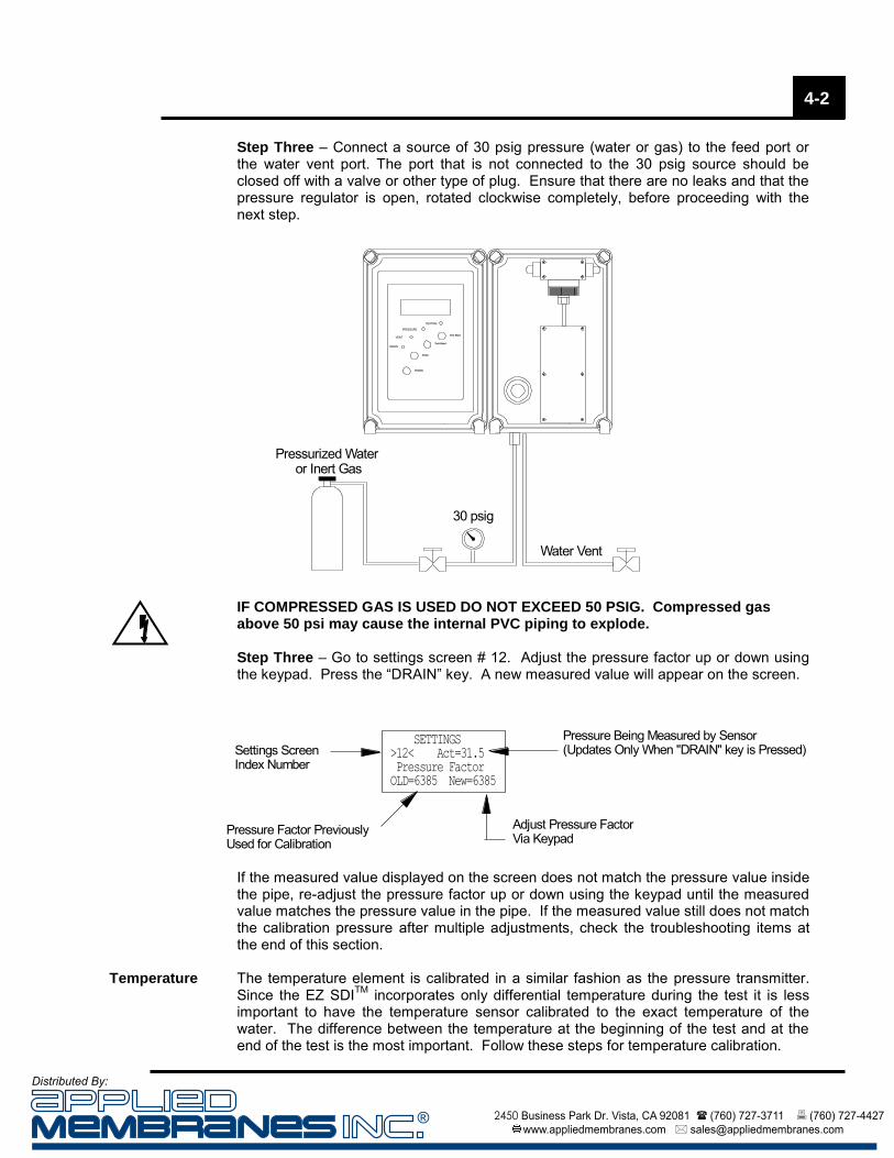
Step Three – Connect a source of 30 psig pressure (water or gas) to the feed port or the water vent port. The port that is not connected to the 30 psig source should be closed off with a valve or other type of plug. Ensure that there are no leaks and that the pressure regulator is open, rotated clockwise completely, before proceeding with the next step.
Water Vent
Test Start
Test Abort
Drain
Display
TESTING
PRESSURE
VENT
DRAIN
30 psig
Pressurized Water or Inert Gas
IF COMPRESSED GAS IS USED DO NOT EXCEED 50 PSIG. Compressed gas above 50 psi may cause the internal PVC piping to explode. Step Three – Go to settings screen # 12. Adjust the pressure factor up or down using the keypad. Press the “DRAIN” key. A new measured value will appear on the screen.
If the measured value displayed on the screen does not match the pressure value inside the pipe, re-adjust the pressure factor up or down using the keypad until the measured value matches the pressure value in the pipe. If the measured value still does not match the calibration pressure after multiple adjustments, check the troubleshooting items at the end of this section.
Temperature The temperature element is calibrated in a similar fashion as the pressure transmitter. Since the EZ SDITM incorporates only differential temperature during the test it is less important to have the temperature sensor calibrated to the exact temperature of the water. The difference between the temperature at the beginning of the test and at the end of the test is the most important. Follow these steps for temperature calibration.
SETTINGS >12< Act=31.5 Pressure Factor OLD=6385 New=6385
Pressure Being Measured by Sensor(Updates Only When "DRAIN" key is Pressed)Settings Screen
Index Number
Pressure Factor PreviouslyUsed for Calibration
Adjust Pressure FactorVia Keypad
4-2
® 2450 Business Park Dr. Vista, CA 92081 (760) 727-3711 (760) 727-4427 www.appliedmembranes.com [email protected]
Distributed By:

Step One – Remove the temperature sensor from the internal piping
TemperatureSensor
EnclosureDoor
Tubing
RegulatorPressure
Transmitter
Step Two – Place the temperature sensor in an ice bath. Allow the sensor to equalize for a few minutes
Step Three – Go to the settings screen # 9. The following screen will appear:
The screen will display the raw analog value being measured from the temperature sensor at zero degrees Celsius (usually a value between 750 and 850). Use the “up” or “down” arrow key to make the “New” value match the "Raw" value and press the “DRAIN” key. The value shown near the top of the screen should match the value entered. If not, wait a minute longer and re-enter the number. Step Four – Place the temperature sensor in a water sample at approximately the same temperature as that being monitored in the process. Measure the temperature with a laboratory grade thermometer. Allow the sensor to equalize to the water temperature for a few minutes before proceeding with the next step.
SETTINGS>9< Raw=837 Temperature Zero OLD=819 New=837
Raw Value Being Measured by Sensor(Updates Only When "DRAIN" key is Pressed)Settings Screen
Index Number
Raw Value PreviouslyUsed for Calibration
Enter Raw Value BeingMeasured
4-3
® 2450 Business Park Dr. Vista, CA 92081 (760) 727-3711 (760) 727-4427 www.appliedmembranes.com [email protected]
Distributed By:

Step Five – Go to settings screen # 10. Adjust the temperature factor up or down using the keypad. Press the “DRAIN” key. A new measured value will appear on the screen.
If the measured value displayed on the screen does not match the temperature value of the water, re-adjust the temperature factor up or down using the keypad until the measured value matches the temperature value of the water. If the measured value still does not match the water temperature after multiple adjustments, refer to the calibration troubleshooting information at the end of this section.
Troubleshooting If problems occur during calibration, please check the following:
Ensure that the settings screen corresponds to the sensor being calibrated. Check the condition of the sensor. Make sure that the electrode surfaces are not
damaged, corroded, or fouled. Check the condition of the sensor wiring and that the sensor leads are properly
connected to the EZ SDITM terminals. Refer to the Troubleshooting Section of the manual for more information.
SETTINGS >10< Act=21.5 Temperature Factor OLD=6385 New=6385
Temperature Being Measured by Sensor(Updates Only When "DRAIN" key is Pressed)Settings Screen
Index Number
Temperature Factor PreviouslyUsed for Calibration
Adjust Temperature FactorVia Keypad
4-4
® 2450 Business Park Dr. Vista, CA 92081 (760) 727-3711 (760) 727-4427 www.appliedmembranes.com [email protected]
Distributed By:

Troubleshooting Guide 5
The following table lists the problems commonly encountered when using the SDI. Please examine the table to identify the cause and correction of your problem. If your problem is not listed or the corrective action does not remedy the problem, call Applied Membranes Inc. at 760-727-3711 or e-mail [email protected]. Problem Probable Cause Corrective Action
Nothing appears on the display and backlight is not illuminated.
No power.
Ensure that 120 / 240 VAC is connected to the proper terminals on the terminal strip. Check condition of fuse in the EZ SDITM fuse holder.
Display does not respond to keypad entries.
Wrong screen on display. Some keypad entries only function on certain screens (i.e., Arrow keys do not function on all displays.)
Damaged keypad.
Contact Distributor
SDI test aborts before test is complete.
SDI too high.
Check pretreatment equipment for proper operation. See next section of troubleshooting guide.
Feed Pressure too low.
Verify that feed pressure to SDI unit is at least 70 PSI. A booster pump may be required if feed pressure cannot be maintained above 70 PSI during the test.
Feed Pressure too high.
Verify that the outlet pressure from the regulator is 30 psi. If regulator will not maintain 30 psi with 70 PSI feed pressure contact Distributor for replacement.
The test aborts before running a SDI15. A “TEST COMPLETE” message is displayed and the SDI5 = 20.00. This is a common problem as there are a number of items that could cause this to happen.
SDI too High. SDI5 is above 20.00. Check pretreatment equipment for proper operation.
Drain solenoid malfunction.
Ensure that the drain solenoid closes during the test. Refer to Drain Solenoid Malfunction troubleshooting elsewhere in this section.
Wrong filter material. Use only approved 0.45-micron filter papers.
Feed solenoid plugged or otherwise restricted.
Flush the feed piping by removing the filter cartridge and starting a test. A large volume of water at a high velocity will be flushed through the unit. The test will abort after about 30 seconds.
Inadequate feed flow or feed pressure to initially fill the chamber within 130 seconds.
Feed pressure drops to less than 70 psi once the test starts. Refer to the pressure troubleshooting elsewhere in this section.
® 2450 Business Park Dr. Vista, CA 92081 (760) 727-3711 (760) 727-4427 www.appliedmembranes.com [email protected]
Distributed By:

Test starts but water does not flow through filter.
Plugged pressure regulator.
Reverse the flow through the regulator. Contact your Distributor.
Malfunction of feed solenoid.
Make sure wiring connections are tight. Contact your Distributor.
Wrong filter material.
Use only approved 0.45-micron filter papers.
Feed source is turned OFF.
Make sure that the feed source is pressurized. Open the feed isolation valve (if installed).
Air gets trapped on filter surface.
Malfunction of vent solenoid valve.
Make sure wiring connections are tight. Contact your Distributor.
Vent orifice is plugged.
Reverse the flow through the air vent. Contact your Distributor.
Test stops but water continues to flow through filter
Malfunction of feed solenoid. Make sure wiring connections are tight. Contact your Distributor.
Volumetric chamber never fills.
Malfunction of drain solenoid.
Make sure wiring connections are tight. Contact your Distributor.
Debris caught in drain solenoid seat.
Disassemble drain solenoid to remove debris. Contact your Distributor.
Volumetric chamber overflows.
Malfunction of drain solenoid.
Make sure wiring connections are tight. Contact your Distributor.
Level sensor dirty, or Level sensor failure.
Clean level sensor eye with cotton swab or other soft cloth. DO NOT USE A CHEMICAL CLEANER on the eye of the sensor as permanent damage to the equipment may occur. Contact your Distributor.
Drain tube plugged or otherwise restricted.
Clean drain tube make sure it flows unrestricted to an open drain without an air lock.
Pressure reading is 50 psi constantly regardless of regulator adjustment.
Water vent tubing is plugged or otherwise restricted.
Clean water vent tube including the orifice inside the tube at origination point. When pressurized the water vent tube should flow approximately 150 mL / Min.
Filter pressure drops below 30 psi when test is started and stays below 30 psi for more than 6 seconds.
Feed pressure drops to less than 70 psi once the test starts.
Increase the feed pressure to more than 70 psi. A booster pump may be required. Move the feed source to after the RO high pressure pump.
Inline screen is plugged or otherwise restricted.
Remove the inline screen and remove any trapped debris.
Pressure regulator is plugged.
Reverse the flow through the regulator by connecting a clean pressurized water source to the water drain connection and opening the feed connection to atmosphere. DO NOT EXCEED 40 PSIG DURING BACKFLUSH!
5-2
® 2450 Business Park Dr. Vista, CA 92081 (760) 727-3711 (760) 727-4427 www.appliedmembranes.com [email protected]
Distributed By:

1
Analog Output Option A 1
Introduction The EZ SDITM is available with an optional analog output board which allows the results of the SDI test to be output as 4-20 mA analog signals. This enables the user to interface the EZ SDITM with PLCs, DCS systems, or data loggers.
Mounting The analog output board is installed at the factory and is mounted on top of the main
CPU board of the EZ SDITM. Access to the terminal blocks on the CPU board for relay outputs and discrete inputs is gained by means of access holes provided in the analog output board (see Figure A-1).
Specifications The EZ SDITM analog output board incorporates the following specifications:
Power Requirements: The board receives operating power from the CPU board. Each analog output loop must be powered with an external supply (12-36 VDC). Isolation: Each analog output is isolated from ground, the EZ SDITM power supply, and the other analog outputs.
0102
0307
0804
0506
SDI 5 Analog Out
CH1CH4
+
-+
-+
-+
-
SDI 10 Analog Out
SDI 15 Analog Out
Not Used
Analog Output Connections
Holes to Access Discrete Inputand Relay Output Terminals
Figure A-1. Overall View of Analog Output Board
® 2450 Business Park Dr. Vista, CA 92081 (760) 727-3711 (760) 727-4427 www.appliedmembranes.com [email protected]
Distributed By:

Outputs The EZ SDITM analog output board is equipped with four, 4-20 mA outputs. On the EZ SDI-1TM, three of these outputs are used to indicate the results of the SDI5, SDI10, and SDI15. The fourth output is not used.
Analog Output Channel One – Results of SDI5, 4-20 mA corresponds to 0-20 SDI units. Analog Output Channel Two – Results of SDI10, 4-20 mA corresponds to 0-10 SDI units. Analog Output Channel Three – Results of SDI15, 4-20 mA corresponds to 0-6.7 SDI units.
Operation Upon resetting the EZ SDITM (for filter replacement), all analog outputs will go to 4 mA.
Upon the conclusion of each portion of the test, the corresponding analog channel will output, and hold, the value corresponding to the test result. The value will be held until the unit is reset for the next test. Should the test fail for high SDI or any other reason, the analog output will be set to 20 mA.
Wiring The wiring diagram for the analog outputs is shown in Figure A-2. When wiring the
outputs, use shielded cable and always route the cable away from sources of interference (AC wiring, motors, etc.)
Figure A-2 illustrates the use of a common power supply. Individual power supplies may be used on each output if loop-to-loop isolation is required. Circuit protection in the analog loop(s) should be provided by the user.
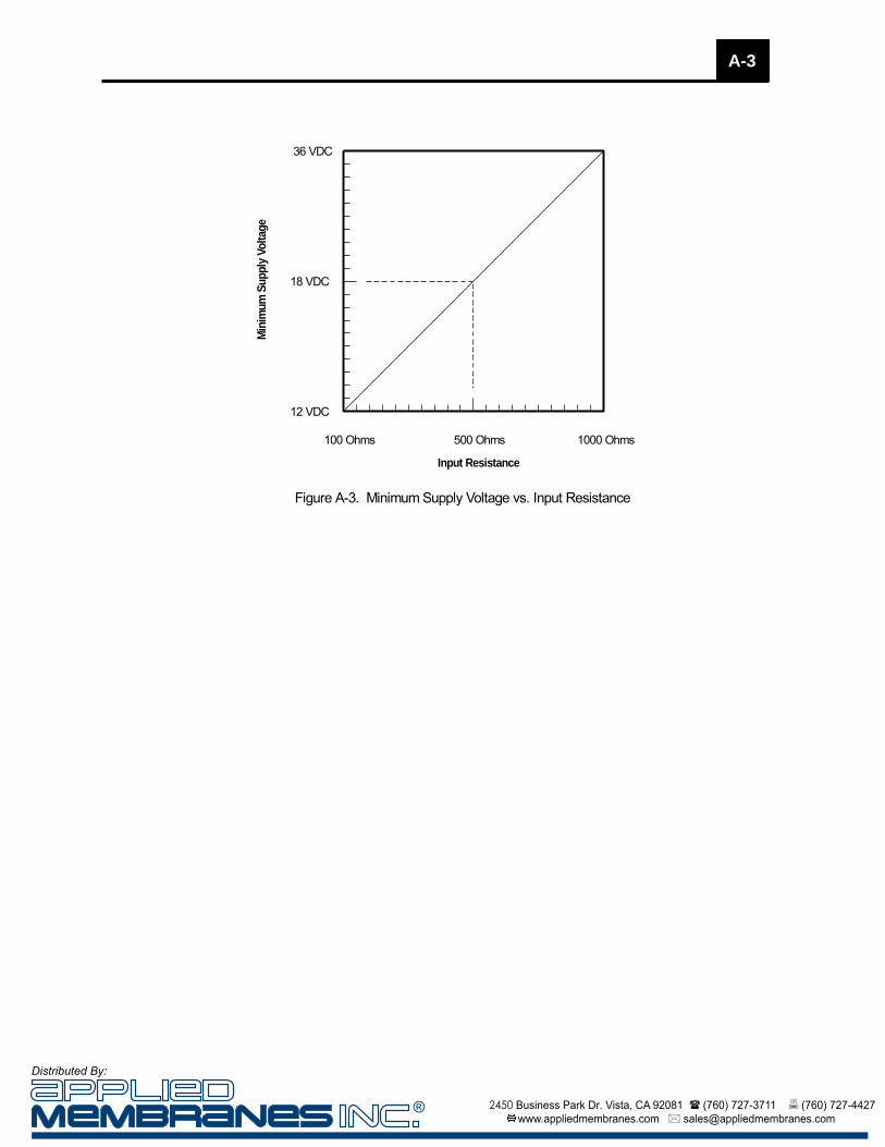
Supply Voltage The minimum supply voltage necessary for the analog output loops is a function of the resistance of the corresponding analog input. Figure A-3 illustrates the minimum voltage necessary as a function of input resistance.
IMPORTANT: Each analog output loop should have at least 100 ohms of resistance or damage to the output circuitry may occur.
0102
0307
0804
0506
SDI 5 Analog Out
CH1CH4
+
-+
-+
-+
-
SDI 10 Analog Out
SDI 15 Analog Out
Not Used
DC Supply12-36 VDC +-
4 -20 mA
4 -20 mA
4 -20 mA
100 mA
Figure A-2. Analog Loop Wiring
> 100 Ohms
> 100 Ohms
> 100 Ohms
A-2
!
® 2450 Business Park Dr. Vista, CA 92081 (760) 727-3711 (760) 727-4427 www.appliedmembranes.com [email protected]
Distributed By:
A-3
100 Ohms 500 Ohms 1000 Ohms
12 VDC
18 VDC
36 VDC
Input Resistance
Min
imu
m S
up
ply
Vo
ltag
e
Figure A-3. Minimum Supply Voltage vs. Input Resistance
® 2450 Business Park Dr. Vista, CA 92081 (760) 727-3711 (760) 727-4427 www.appliedmembranes.com [email protected]
Distributed By:

NOTES:
® 2450 Business Park Dr. Vista, CA 92081 (760) 727-3711 (760) 727-4427 www.appliedmembranes.com [email protected]
Distributed By: