Embed Size (px)
Citation preview

Silo Technology
Silo Discharge Devices

2
altmayerBTD GmbH & Co. KG is the right partner for system, bin, energy and environmental technology.
Our tradition-rich company’s product portfolio ranges from bin and reservoir technology to heating and
drinking water systems and solar technology, to storage and transport of bulk solids.
Our silos are well known wherever bulk solids are stored, processed or transported. They come in vol-
umes from 50 m³ to 5,000 m³ and in diameters from 2,500 mm to 15,000 mm. They have various designs,
are made from different materials and are adapted to the demands of the solids being stored. For a sure
and continuous discharge, there are a number of special discharge devices to choose from.
For explosive solids or special processes, our pressure-shock-resistant or pressure-tight silos are sui-
table. They meet very high safety standards and comply with the applicable European norms. Whether
factory prepared or welded on site, altmayerBTD silos offer the best possible technology, efficiency and
durability.
What do we offer?

3
Silo Technology
As a result of our experience in many different industrial sectors and the wide range of our portfolio, we
can offer the optimal solution for each application, if it is about transport, storage and handling of the most
varied kinds of bulk solids.
Whether it is factory-welded silos up to 300 m³, standard silos or silos up to 5,000 m³ welded on site,
altmayerBTD is your expert partner for design, planning construction, installation and set-up of silo sys-
tems.
altmayerBTD’s management system complies with the requirements of ISO 9001:2008. The company is
not only certified for producing pressure devices according to pressure equipment directive 97/23 EG
(modules G and B1 + F), but also holds manufacturer qualification for welding steel structures per DIN
18800-7:2002-09 class E.
Factory-Welded Silos
The company’s production capabilities allow construction of factory-welded silos of diameters from
1,800 mm to 4,400 mm and volumes from 5 m³ to 300 m³. Addition of accessory parts, such as filters,
overflow protection, discharge aids, etc., and complete electrical cabling and controls right from the fac-
tory provide decisive advantages. A system is delivered to the customer that has already undergone de-
manding tests on the manufacturer’s own premises. This reduces on-site installation work to a minimum,
so that the system can be started up shortly after delivery.
The silos come in various designs:
• Single-chambersilos
• Multiple-chambersiloswithoneortwopiecepartitions
• Siloswithoneormoreoutlets
• Placementonsteelconstructionorskirtsupport
• Siloswithconicalorflatbottom
• Silosforpressure-freeoperationorpressure-shock-resistant/pressure-tightsilos

Silos Welded on Site
Beyond a certain size, silos welded on site are used
to reduce transport and handling costs. For this,
precisely fitted segments are put together in our
factory and taken to the construction site as trans-
portable, installation-ready units. There, the parts
are assembled and welded into a whole.
In this way, even silos with diameters up to
15,000 mm and a volume of 5,000 m³ can be built
individually. In contrast to bolted silos, the welded
design ensures that the silo body is completely
sealed.
Like factory-welded silos, silos welded on site come
in various versions.
Standard Silos
Standardization of individual silo systems guaran-
tees cost effectiveness and short delivery times,
but also a high level of mature technology.
This applies especially to our 120 m³ coal dust si-
los, which have been produced in large numbers
for many years. These silos meet the highest safe-
ty standards and are transported to the installation
site as a complete unit.
Within a day, they are ready to operate and can be
connected to the other assemblies.
Despite standardization, we maintain a high de-
gree of flexibility to meet our customers’ individual
requirements.
Silo Technology
4

Explosion Resistant Silos
For storage of explosive solids, we offer special silos with an explosion-resistant design. A distinction is
made between silos that are pressure-tight (no deformation allowed) and pressure-shock-resistant (defor-
mation allowed). The silos are designed for either the solid’s maximum explosive pressure (up to 9 bar) or,
in case explosion pressure relief is used, for the reduced explosive pressure (generally 2 bar).
We make not only static calculations for pressure-shock-resistant silos, but also the calculations for the
pressurereliefsurfaceaccordingtoVDI3673orNFPA68.Ourapprovedexplosionflapsprotectourpres-
sure-relieved silos. In the event of an explosion, the explosion flap will open and allow the silo to relief
pressure. Unlike rupture disks, explosion flaps are self-closing and can be used again after an explosion.
If needed, we equip explosion flaps with underpressure safety mechanisms and electric heating.
We have decades of expertise in this field and guarantee our customers the highest quality and greatest safety.
Silo Technology
5

Complete Silo Technology from One Source
altmayerBTD discharge devices are the core of a comprehensive storage, transport and processing
programforbulksolids.Planning,productionandinstallationfromonesourceguaranteeflexibilityanda
high standard of quality. Take advantage of our company’s expertise and technical capabilities. We are
deeply involved in developing bulk solids processing technology.
Industry Solids
LINEX
Waste water treatment Sewage sludge, industrial sludge, filter cake Wood industry, fibre industry Shavings, sawdust, wood chips Wastetreatment Pasty,lumpywastesPowerplants,incinerators Sewagesludge,alternativefuelsDryingfacilities Pastematerials
ROTEX®
Cement industry Raw coal, FGD gypsum, petroleum coke, cement, clinker, gypsum, marl, clay, slag sandRocks and soils Sand, rocks Powerplants FGDgypsum,rawcoal,flyash,furnaceash,residuesSteel works, aluminium industry Blast furnace slag, raw coal, coke, ores, bauxite, iron ore pellets Lime production Limestone, raw coalWaste incineration plants Ash, slag Chemical industry Salts, soot, plastic granules Waste water treatment Sewage sludge, industrial sludge, filter cake Wood industry, fibre industry Tree bark, shavings
ROTAFLOW®
Foodindustry Milkpowder,sugar,instantpowders,flour,soyflourPowerplants Groundlimestone,hydratedlime,finecoal,coaldustRocks and soils Clay, cement, gypsum, limestone, marl, coal dust, ground slate, silica sand Chemicalindustry Pigments,fertilizers,pesticides,plasticgranules,glass fibre, oxides, sodium chlorate, sodium powder, silicic acid, lead oxide, detergent, graphite, barium, potash, chalk, titanium oxide, soot, coal dust Steel works, aluminium industry Foundry sand, binders, aggregates, fine coal, coal dust Wood industry Wood shavings, sawdust Water treatment Ground limestone, hydrated lime, flocking agent, aggre- gates, activated carbon, hard coal dust Glass industry Aggregates, sand, glass batch, pigments
Technical Solids and Applications for the Silo Discharge Devices
Silo Discharge Devices
6

Industry Solids
Agitator
Foodindustry Milkpowder,sugar,instantpowders,flour,soyflourPowerplants Groundlimestone,hydratedlime,finecoal,coaldustRocks and soils Clay, cement, gypsum, limestone, marl, coal dust, ground slate, silica sand Chemicalindustry Pigments,fertilizers,pesticides,plasticgranules,glassfibre, oxides, sodium chlorate, sodium powder, silicic acid, lead oxide, detergent, graphite, barium, potash, chalk, titanium oxide, soot, coal dust Steel works, aluminium industry Foundry sand, binders, aggregates, fine coal, coal dust Wood industry Wood shavings, sawdust Water treatment Ground limestone, hydrated lime, flocking agent, aggregates, activated carbon, hard coal dust Glass industry Aggregates, sand, glass batch, pigments
Fluidization
Foodindustry Milkpowder,sugar,instantpowders,flour,soyflourPowerplants Groundlimestone,hydratedlime,finecoal,coaldustRocks and soils Clay, cement, gypsum, limestone, coal dust, ground slate, silica sand Chemicalindustry Pigments,fertilizer,pesticide,sodiumpowder, silicic acid, lead oxide, detergent, graphite, barium, potash, chalk, titanium oxide, soot, coal dust Steel works, aluminium industry Foundry sand, binders, aggregates, fine coal, coal dust Water treatment Ground limestone, hydrated lime, flocking agent, aggregates, activated carbon, hard coal dust Glass industry Aggregates, sand, glass batch, pigments
VIBREX
Foodindustry Milkpowder,sugar,instantpowders,flour,soyflourPowerplants Groundlimestone,hydratedlime,finecoalRocks and soils Clay, cement, gypsum, limestone, ground slate, silica sand Chemicalindustry Pigments,fertilizer,pesticide,plasticgranules,glassfibres, oxides, sodium chlorate, sodium powder, silicic acid, lead oxide, detergent, graphite, barium, potash, chalk, titanium oxide, soot, coal dust Steel works, aluminium industry Foundry sand, binders, aggregates, fine coal Wood industry Wood shavings, sawdust Water treatment Ground limestone, hydrated lime, flocking agent, aggregates Glass industry Aggregates, sand, glass batch, pigments
Silo Discharge Devices
7

Silo Discharge Devices - mechanical
LINEX
Safe Silo Discharge for Bad Flowing Bulk Solids
Solids with extremely bad flow characteristics and considerable time compaction can form arches of
several metres. Very steep hopper slopes are necessary to achieve mass flow. As it is not desirable for
technical and economic reasons to build a silo with correspondingly large outlet diameters and steep
hopper walls, the LINEX silo discharge device is the suitable solution to strip the solids from the entire
diameter of the silo.
1 Slide frame2 Even discharge platform3 Drive cylinder4 Hydraulic unit5 Discharge screw
1
12
33
4
5
8

9
Benefits
• Fullactivationofthesilocrosssection
• Lessspaceconsumptionduetoalineardriveinstalleddirectlyonthesilowall
• Easymaintenancethankstoexternaldriveandsealcomponents
• Reducedsiloheight
• Easyretrofittingtoexistingsilos
• Preventionofmaterialcompactionduetohydraulicunitpressurelimits
• Safeoperationevenafterlongdowntime
Operation
The outlet diameter necessary for preventing arching or ratholing is also the input diameter of the LINEX
silo discharge device. An ovular slide frame oscillates over a level discharge platform with one or more
outlet slots. In the case of a rectangular bin, one or more rectangular slide frames are used. The slide
frame has a wedge profile. With each translational movement of the slide frame, the standing edge of the
wedgeprofile,whichisorientedtowardstheoutletslot,slidestheproductintotheoutlet.Meanwhile,the
flat side of the wedge profile on the opposite side undercuts the product. The slide frame is driven by a
hydraulic cylinder with a hydraulic unit. If the slide frame’s end positions are not reached, due to localized
material compaction or foreign objects, a pressure limit for the hydraulic drive initiates a reversal move-
ment of the slide frame. This means that even in this case, safe silo discharge is maintained. Below the
silo discharge opening there are one or more floor-mounted discharge screw conveyors. According to
requirements, the discharge can be arranged in the middle or on each face of the silo.
Technical Data
The LINEX silo discharge device is available in various designs. For both basic forms of the slide frame,
one or more cylinders can provide the drive. Discharge can be central, one-sided or two-sided using one
or more screw conveyors. The device offers a multitude of possibilities for system- and material-specific
designs.
Materials
• Standardsteel
• Standardsteel,coated
• Stainlesssteel
• Wear-resistantsteel
Silo Discharge Devices - mechanical

Silo Discharge Devices - mechanical
ROTEX®
Efficient Silo Discharging Devices for Smooth Operation
Storing and conveying bad flowing solids are sen-
sitive processes in ore processing, the chemical
industry, waste incineration, wood chip recycling,
coal loading at power plants, and removal of flue
gas gypsum or ashes, to name just a few exam-
ples.
Designing a silo for bad flowing solids sets pro-
cess engineers a most difficult task. At this, it is
important to specify the limit conditions for the silo
geometry and the abrasion behaviour of the solids towards the wall to guarantee safe discharge of the
material. As a result of the two extreme flow types in silos, mass and funnel flow, operational interruptions
are to be expected with materials that do not flow freely. With funnel flow, generally only one column of
material empties above the outlet opening, so that part of the material remains in the body of the silo. With
mass flow, a stable arch of material can form above the outlet opening, so that removal is blocked.
Benefits
• Firstin/firstoutprinciple
• Fullactivationofthesilocrosssection,evenwithdifficultproducts,throughnegativesilo
geometry
• Safeoperationevenafterlongdowntime
• Pressure-relieveddischarge
• Extremelyrobustsilodischarge
• Lowenergyrequirements
• Driveelementsfreelyaccessiblefromexterior
• Adjustmentofdischargeoutputusinganadjustingringwhenempty
• Grainsizesupto250mm
• Dischargevolumesupto2,000m3/h
10

1 Ventilation port 2 Exhaust air filter 3 Fill level measurement 4 Internal relief cone 5 Height-adjustable guide plates 6 Discharge platform of wear-resistant, high-strength steel7Piniondrive,slewbearing 8 Grease pump control — on site 9 Grease pump10 Spur-gear drive motor11 Discharge chute12 Sealing element13 Discharge arm
13 2
4
5
136
7 8
910
1112
Operation
Demand for safe, dispensed discharge of extremely bad flowing materials, combined with the advan-
tages of mass flow silos has led to the development of the ROTEX® bunker discharge device. Over a
horizontal floor with a central opening, a logarithmically formed discharge arm moves the material away
from the periphery and towards the opening. The special shape of the discharge arm prevents compac-
tion of the materials during the discharge movement. A relief cone over the discharge chute takes over a
large part of the material load. Relieving the discharge area prevents compaction of the materials in the
discharge area, even during long downtimes.
The choice of design parameters is specified according to the characteristics of the material and
guarantees discharge behaviour with the advantages of mass flow silos. Among other things, the cone
angle, the gap width between the cone and the outer cylinder, the height of the constriction ring, the
sheet metal surface characteristics, the shape of the cylindrical material and possible undercutting of
the discharge arm are considered. The constriction ring can be adjusted from underneath and allows
later adjustment of the flow behaviour to various silo materials.
11
Silo Discharge Devices - mechanical
Funnel flow Massflow

12
Technical Data
The ROTEX®bunkerdischargedevice isavailable inawidevarietyof standardsizes.Production in
intermediate sizes allows the whole silo system to be tailored to the operator’s economic and technical
requirements. Even custom designs, such as the explosion-resistant construction according to VDI 3673,
with all associated system components and pressure relief equipment can be supplied, thanks to the ex-
perience of a pioneer in this field. ROTEX® bunker discharge devices are suitable for discharging solids
with grains up to 250 mm, with a discharge volume up to 2,000 m³/h.
Certified per 94/9/EG: BVS 08 ATEX H 024 X
The experiment represented below shows the flow profile determined and confirms the exemplary behav-
iour of the ROTEX® bunker discharge device, which lowers the material surface uniformly in almost all
diameters. This prevents dead zones and segregation, keeps the material discharge constant and even
bad flowing materials are safely discharged and dosed.
Silo Discharge Devices - mechanical

Silo Discharge Devices - mechanical/pneumatic combined
ROTAFLOW®
Uniform Material Discharge with Mass Flow Behaviour for Silos with Several Outlets
When a silo is being emptied, exit problems often
occur with arching or ratholing in a functionally inap-
propriate silo design.
For solids fl owing in silos, a distinction is made
between mass fl ow and funnel fl ow. While with mass
fl ow all the material in the silo moves, it is mostly the
material above the discharge that moves with funnel
fl ow. As a result of funnel fl ow behaviour dead zones
and compaction of the material in this area arise. On
the other hand, with mass fl ow the material surface
sinks uniformly. The material is discharged without
segregation. If the discharge opening in a mass fl ow silo is too small, a stable arch of material will form
above it. In contrast, if the discharge opening is too small in a funnel fl ow silo, both arches and ratholing
can occur. In both cases, the product discharge comes to a complete standstill. With suffi ciently large exit
diameters, however, discharge mass fl ow rates often occur that are far larger than the required values. In
silos that have several independently operated outlets, these problems take on added signifi cance.
Benefi ts:
• Fullactivationoftheactivatorinflowdiameter
• Safeoperationevenafterlongdowntimeorafterdowntimeatindividualoutlets
• Noverticalactivatormovement—thusnomaterialcompaction
• Reverseswitchingtobreakupcakedmaterial
• Easyretrofittingtoexistingsilos
• Reducedsiloheight
• Simplemaintenancewithexternalandexternallyremovabledrive,bearingandsealelements
• Canbeusedwithanysilosize
13

1 Central cone 2 Revolving activator blade 3 Welding neck flange 4 Fluidizing air pipe 5 Compensator6Pneumaticslidegate 7 Fluidizing nozzles 8 Dome activator base 9 Grease pump 10 Discharge chute 11 Gear motor 12 Speed monitor 13 Bearing and coupling unit
1 2
3 4
56
7
89
10
1112
13
Operation
The outlet diameter necessary for preventing arching or shafts is also the inflow diameter of the ROTA-
FLOW® solids activator. Over the vaulted activator base, there is a centrally placed rotating activator bla-
de of wear-resistant, high-strength steel. The driveshaft is securely sealed at the silo’s exterior by several
externally removable special gaskets. A grease pump safely lubricates all bearings. In the vulnerable silo
cross section, the rotary activator blade discerns the entire column of solids and prevents inactive zones
from forming.
The solids are pulled away from the entire cross-section of the activator by the spatial effect towards the
circumferenceassociatedwiththerotationalmovement.Materialcompactionisimpossibleeveniftheout-
let diameters are closed, because the activator acts on the material only at horizontal planes. The special
dispersal nozzles built into the activator base guarantee easy activator start-up even after long downtimes.
To support subsequent metering devices, air can also be fed in dependent on the gear motor’s power
consumption. Once the constant power consumption is reached, a constant density of the material can be
assumed. The possibility to reverse the activator rotation in relation to the gear motor’s power consumption
guarantees breakup of localized material compaction after long system downtimes.
Silo Discharge Devices - mechanical/pneumatic combined
14
Technical Data
Size: DN 1800
DN 2600
Pressureshockresistance: 2bar
9 bar
Materials: Standardsteel,
Wear-resistant
steel,
Stainless steel
Certified per 94/9/EG BVS 05 ATEX
H 007 X

Silo Discharge Devices - mechanical/pneumatic combined
Agitator
Metered Material Discharge with Bad Flowing Solids for Silos with Several Outlets
When fine-grained, bad flowing solids are stored in
improperly dimensioned silos, malfunctions develop
due to arching or funnel flow.
While as a result of arching the silo discharge comes
to a complete standstill, with funnel flow complete
emptying is prevented by ratholing. This flow behav-
iour results in operational downtime, segregation
of products, grain shrinkage, dead zones, material
flooding when the funnel walls collapse, incomplete
silo emptying and non-uniform flow behaviour.
These problems become more significant if the silo
has several independently operated outlets. The
discharge mass flow rates of the individual outlets become mutually dependent, and after long outlet
downtime it becomes hard to activate the material flow again.
Benefits
The mature design of the discharge agitator with its robust, durable construction offers special benefits
in a wide range of applications.
• Safe,dispensedproductdischargewithmassflowbehaviourforbadflowingsolidsinbins
with several outlets
• Noarchingorratholing
• Pressure-relievedoutlets,trouble-freecontinuousfeedingofconveyingandmeteringsystems
• Fullactivationoftheoutletdiameter
• Safeoperationafterlongdowntimesofthesystemorofindividualoutlets
• Homogenizationofmaterialthroughanintensivemixingeffect
• Canbeusedevenathightemperatures
• Virtuallymaintenance-freeoperation
• Lowenergyrequirement
15

16
Silo Discharge Devices - mechanical/pneumatic combined
• Canbeadaptedtovariousbunkershapes
• Canberetrofittedtoexistingsilos
• Canbeusedwithanysilosize
Operation
Motivatedbyconstantly repeatedoperationalproblems insiloswithseveraloutlets,altmayerBTDhas
developed a discharge agitator integrated into the cone end of the silo. The basic shape of the hopper is
that of a wedge. The wedge-shaped hopper guarantees flow conditions significantly better than those in
conical hoppers when it comes to mass flow behaviour. Another important advantage is the fact that the
circular discharge opening’s diameter — which prevents arching — is about double the size of the narrow
side of the wedge.
The robust discharge agitator, flange mounted to the hopper outlet, has a massive agitator shaft and is
driven by a slow-running spur-gear drive motor. The shape and size of the agitator scrapers set on the
shaft are determined by the material characteristics and the discharge geometry of the individual outlets.
There are also special designs with additional horizontal activators. The special aeration nozzles built into
the cone end and the agitator trough guarantee easy start-up even after long downtimes.
To achieve high volumetric metering precision of the subsequent metering devices, air can also be fed
depending on the gear motor’s power consumption. Once the constant power consumption is reached,
a constant density of the material can be assumed. The discharge agitator meets the need for complete
activation of the silo outlet diameter while restricting the mass flow rate as needed. Subsequent metering
devices redirect the loosened mass flow. This prevents compaction and shearing of the material and
reduces the risk of the material flowing only in preferred areas by the principle of least resistance. This
allows direct installation of rotary feeders or screws.
Another possible application of the discharge agitator is in silos with pneumatic discharge equipment
for cohesive solids that are extremely difficult to fluidize. Aeration must lift these materials as a whole, or
cracks and ratholes will form. Only with mechanically supported fluidization fluidized beds do form and
guarantee trouble-free discharge. The size of the discharge agitator is determined by the number and
size of the subsequent metering devices, as well as by the need to prevent arching over the narrow side
of the agitator, and to prevent funnel flow.

17
Technical Data
Length: 1,000 to 4,500 mm
Pressureshockresistance: 2bar
9 bar
Materials: Standardsteel,wear-resistantsteel,stainlesssteel
1 Exhaust air fi lter 2 Filling dome3Positive/negativepressurevalve 4 Continuous fi ll level measurement 5 Filling pipe 6 Fluidizing air pipes 7 Fluidizing nozzles 8 Couplings 9 Spur-gear drive motor 10 Speed monitor11 Agitator shaft12 Agitator scraper13 Special gasket14Pedestalbearing
Silo Discharge Devices - mechanical/pneumatic combined
1
23
4
5
6
78 9
10 11 12 1314

Silo Discharge Devices - pneumatic
Fluidization
Uniform Material Discharge with Mass Flow Behaviour for Siloswith One or More Outlets
During storage in bins or silos, many materials tend to de-aerate or compact. Their flow characteris-
tics change, often causing operational problems when emptying. These are distinguished by arching or
ratholing. If the discharge opening is not big enough, a stable arch of material will form above it.
On the other hand, ratholing (funnel flow) results in dead zones and time compaction in these areas.
Achieving mass flow with these materials requires steep hopper slopes and large outlet diameters, which
are often undesirable for technical and economic reasons.
Benefits
altmayerBTD has many years of experience in bulk materials technology, so our customers always get
the technically and economically optimal solution. Besides laboratory investigation of the material charac-
teristics, this also includes the design of the silo geometry and choice of the necessary equipment. This
provides the customer with the following benefits:
• Safe,dispensedproductdischarge
• Noarchingorratholing
• Massflowcharacteristicsinthesilothroughreductionofwallabrasionforcesandreduction
of internal friction
• Robustdesignforlonglife
• Canbeadaptedtovariousbunkershapes
18

• Optimalsilodischarge
• Lowenergyrequirement
• Longerstorageperiodsarepossible,safedischargeevenafterlongdowntimes
• Canbeusedevenathightemperaturesorpressures
Operation
Through fluidization, flow with air or another gas, certain materials can be converted to a fluid-like state.
Air input loosens masses of fine-grained particles so that they behave like a liquid and display good flow
characteristics.
The air reduces the friction between the particles and against the hopper wall. This allows flatter hopper
slopes and smaller outlet diameters. The result is a mass flow silo without dead zones and the associated
risk of time compaction and self ignition.
For fluidization, many elements are available that allow optimal adaptation of the system to the specific
characteristics of the material and the silo geometry.
For extensive aeration, special pneumatic tissue covered flutes or boxes are used. Especially with large
silos, this allows flat hopper slopes and lower construction heights. Furthermore, it allows construction of
bins for homogenization of bulk solids. Strips or pads of porous materials — plastics or metals — allow air
introduction in applications where either purity (e.g., in the food industry) or temperatures and pressures
in the bin are important.
Aeration nozzles also guide gases into the material mass, such as for fire fighting in silos by inertization
with nitrogen or carbon dioxide.
With cohesive, very fine-grained materials, special aeration nozzles are used that pulse air against the
hopper wall to reduce wall wear and fluidize the material. The intermittent air input prevents the ratholing -
typical of cohesive solids, through which the air uselessly escapes upward or through the outlet nozzle.
Another advantage of this manner of aeration is the reduction of the amount of required air to a minimum.
After all, production and processing of compressed air is expensive. Besides this, compressed air is un-
desirable in several processes, such as with flammable or hygroscopic dusts.
19
Silo Discharge Devices - pneumatic

Silo Discharge Devices - vibration
VIBREX
Metered Material Discharge with Bad Flowing, Fine-Grained Solids
In storing, conveying and metering bad flow-
ing solids, only especially powerful bunker
discharge equipment guarantees a friction-
less metering process. For emptying silos,
the type of material flow is largely determined
by the silo geometry and the internal friction
of the material and the wall friction.
A distinction is made between mass flow and
funnel flow. With funnel flow it is mostly the
material above the outlet in the funnel that
moves. A flow funnel is formed by the sinking
of the material surface in the silo’s core area
and by subsequent flow of the material on
the surface from the sides of the centre of the
silo. This flow behaviour results in segregation of products, dead zones, material flooding when the funnel
walls collapse, incomplete silo emptying and non-uniform flow behaviour. On the other hand, with mass
flow all the material in the silo moves. The material surface sinks uniformly during discharge. This means
that the bin’s entire volume is used, and the least possible segregation is achieved, along with constant
bulk density during emptying. Thus, only a mass flow silo fulfils the basic task of discharging the stored
material trouble-free, in unchanged quality.
To prevent stable arches of material above the exit openings, their smallest dimension must exceed a min-
imum value that can be specified according to the Jenike process. With these exit diameters, however,
discharge mass flow streams often occur that are far larger than the required values.
Benefits:
The mature design of the VIBREX silo discharge device with its robust, durable design offers special
benefits in a wide range of applications:
• Safe,meteredproductdischargewithmassflowbehaviourforbadflowingsolids
• Noarchingorratholing
• Effectivereductionofwallfrictionandinternalfrictionwithinthematerial
• Pressure-relievedhopperfortrouble-freecontinuousfeedingofconveyingandmetering
systems
20

• Removal-orientedmaterialactivation,preventingadditionalcompaction
• Homogenizationofmaterialthroughanintensivemixingeffect
• Optimalsilodischarge
• Canbeusedevenathightemperatures
• Virtuallymaintenance-freeoperation
• Lowenergyrequirement
• Canbeadaptedtovariousbunkershapes
• Canberetrofittedtoexistingsiloswithoutchangingtheheightorthedownstreamconveying
and metering systems
• Canbeusedwithanysilosize
Operation
Demand for safe, metered discharge with mass flow behaviour with an outlet diameter adapted to the
design requirements has led to development of the VIBREX silo discharge device for bad flowing, fine-
grained materials.
Above the load relief dome, there is an embedded vibration frame driven by a vibration drive with con-
tinuously adjustable unbalance force. The driveshaft is securely sealed at the silo’s exterior by a special
externally removable gasket. The size and width of the side ring gap are determined by the individual
characteristics of each material. With directed horizontal vibrations, the vibration frame activates the
entire diameter of the material above the load relief dome. The flow movement extends across the entire
diameter of the bunker and displays mass flow behaviour. The solid flows into the free volume of the cone,
which is released from the solid pressure and through this release, the solid displays considerably better
flow characteristics. Additionally, the vibration arms, which are adjusted to the slope of the cone, improve
the flow behaviour in the free volume of the cone.
The material’s flow behaviour at the individual base openings creates an intense mixture effect, which
greatly contributes to the material’s homogeneity. The air which is displaced by the material flow into the
free volume of the cone is guided through a release line to the silo head area. Conversely, the vacuum
created in the bunker top during discharge is reduced by a return air stream. The vibration frame of the
load relief dome works intermittently between the two material levels determined by the level indicator in
the cone area.
Silo Discharge Devices - vibration
21
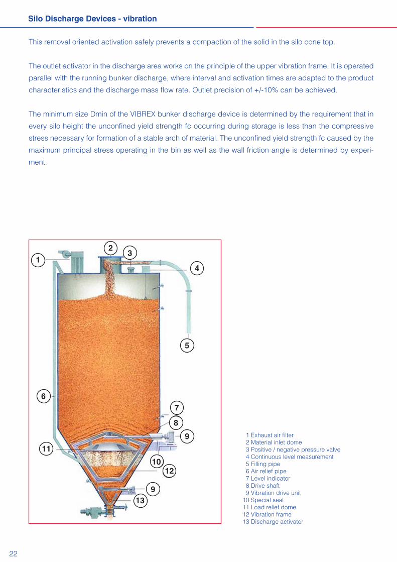
1 Exhaust air filter2Materialinletdome3Positive/negativepressurevalve 4 Continuous level measurement 5 Filling pipe 6 Air relief pipe 7 Level indicator 8 Drive shaft 9 Vibration drive unit10 Special seal11 Load relief dome12 Vibration frame13 Discharge activator
12
3
4
5
67
8
9
10
11
12
139
22
Silo Discharge Devices - vibration
This removal oriented activation safely prevents a compaction of the solid in the silo cone top.
The outlet activator in the discharge area works on the principle of the upper vibration frame. It is operated
parallel with the running bunker discharge, where interval and activation times are adapted to the product
characteristics and the discharge mass flow rate. Outlet precision of +/-10% can be achieved.
The minimum size Dmin of the VIBREX bunker discharge device is determined by the requirement that in
every silo height the unconfined yield strength fc occurring during storage is less than the compressive
stress necessary for formation of a stable arch of material. The unconfined yield strength fc caused by the
maximum principal stress operating in the bin as well as the wall friction angle is determined by experi-
ment.

subj
ect t
o ch
ange
01/
11
altmayerBTD GmbH & Co. KG
Headquarters: System technology: Representatives: Brückenstraße1 Südstraße14 SantaSanayiMamulleriTIC. DearbornMid-WestConveyorCo.72135Dettenhausen 66780Rehlingen veSan.Ltd.Sti. 4220ShawnaMissionParkwayGermany Germany Ankara/Turkey Suite 301 BTel.: +49 (0) 71 57 5 62-0 Tel.: +49 (0) 68 35 91 93-0 Tel.: +90 3 12 3 42 52 50 Fairway KS 66205/USAFax: +49 (0) 71 57 6 10 00 Fax: +49 (0) 68 35 91 93-29 Fax: +90 3 12 2 95 97 26 www.santa.com.tr [email protected] www.altmayerbtd.de
Our powerful brands
byICHERHEITS ITM YSTEMS
BTDaltmayer
AIRDOS® ROTEX® ROTAFLOW®