Embed Size (px)
Citation preview

FIORI GROUP S.p.A.Via per Ferrara, 7
41034 FINALE EMILIA (Modena Italy)Tel. +39.0535.92357 - Fax +39.0535.90960
http://www.fi origroup.com
HORIZONTAL SILO
Model HS15.0 - HS35.0
USER AND MAINTENANCE MANUAL
REF. 9301369200 ed. 00
id.: SILO HS15.0 - HS35.0 REV. 01 21/04/2016
en_UKTRANSLATION FROM ORIGINAL LANGUAGE

id.: SILO HS15.0 - HS35.0 REV. 01 21/04/2016
CAUTION
For reasons of clarity, some illustrations in this manual show the vehicle without guards.
Never use the vehicle without the guards and do not start the engine when the engine guard
is open unless expressly indicated in the maintenance operations.
CAUTION
STUDY THIS MANUAL BEFORE USING THE MACHINE!
Operators and maintenance staff must read this manual carefully before using the machine or carrying out maintenance work. In case of doubts, ask your Dealer or employer. Do not attempt to guess solutions you are uncertain of, as this can result in serious damage or injury. This handbook must be kept with the machine for reference, and must accompany the machine when it is sold on.


id.: SILO HS15.0 - HS35.0 REV. 01 21/04/2016
INDEX
INTRODUCTION
TECHNICAL FEATURES
SAFETY EQUIPMENT
INSTALLATION
OPERATION AND USE
TRANSPORT AND HANDLING
MAINTENANCE
1
0
2
3
4
5
6
7

7id.: SILO HS15.0 - HS35.0 REV. 01 21/04/2016
INDEX
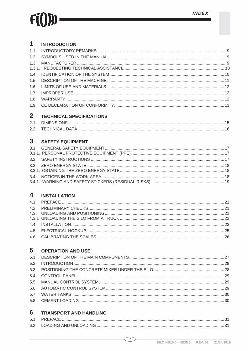
1 INTRODUCTION1.1 INTRODUCTORY REMARKS ................................................................................................................91.2 SYMBOLS USED IN THE MANUAL ......................................................................................................91.3 MANUFACTURER .................................................................................................................................91.3.1. REQUESTING TECHNICAL ASSISTANCE ...................................................................................... 101.4 IDENTIFICATION OF THE SYSTEM ...................................................................................................101.5 DESCRIPTION OF THE MACHINE .....................................................................................................111.6 LIMITS OF USE AND MATERIALS .....................................................................................................121.7 IMPROPER USE ..................................................................................................................................121.8 WARRANTY .........................................................................................................................................121.9 CE DECLARATION OF CONFORMITY ...............................................................................................13
2 TECHNICAL SPECIFICATIONS2.1. DIMENSIONS .......................................................................................................................................152.2. TECHNICAL DATA ..............................................................................................................................16
3 SAFETY EQUIPMENT3.1 GENERAL SAFETY EQUIPMENT .......................................................................................................173.1.1. PERSONAL PROTECTIVE EQUIPMENT (PPE) ................................................................................173.2 SAFETY INSTRUCTIONS ...................................................................................................................173.3 ZERO ENERGY STATE .......................................................................................................................183.3.1. OBTAINING THE ZERO ENERGY STATE ..........................................................................................183.4 NOTICES IN THE WORK AREA ..........................................................................................................183.4.1. WARNING AND SAFETY STICKERS (RESIDUAL RISKS) ...............................................................19
4 INSTALLATION4.1 PREFACE ............................................................................................................................................214.2 PRELIMINARY CHECKS .....................................................................................................................214.3 UNLOADING AND POSITIONING .......................................................................................................214.3.1 UNLOADING THE SILO FROM A TRUCK ..........................................................................................224.4 INSTALLATION ....................................................................................................................................234.5 ELECTRICAL HOOKUP .......................................................................................................................254.6 CALIBRATING THE SCALES ..............................................................................................................26
5 OPERATION AND USE5.1 DESCRIPTION OF THE MAIN COMPONENTS ..................................................................................275.2 INTRODUCTION ..................................................................................................................................285.3 POSITIONING THE CONCRETE MIXER UNDER THE SILO .............................................................285.4 CONTROL PANEL ...............................................................................................................................295.5 MANUAL CONTROL SYSTEM ............................................................................................................295.6 AUTOMATIC CONTROL SYSTEM ......................................................................................................295.7 WATER TANKS ...................................................................................................................................305.8 CEMENT LOADING .............................................................................................................................30
6 TRANSPORT AND HANDLING6.1 PREFACE ............................................................................................................................................316.2 LOADING AND UNLOADING ..............................................................................................................31
SILO HS15.0 - HS35.0 REV. 01 21/04/2016
8id.:SILO HS15.0 - HS35.0 REV. 01 21/04/2016
INDEX
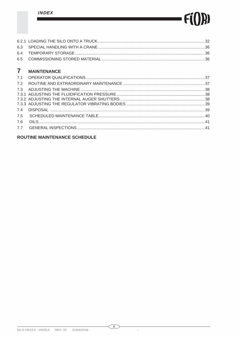
6.2.1 LOADING THE SILO ONTO A TRUCK ................................................................................................326.3 SPECIAL HANDLING WITH A CRANE ...............................................................................................366.4 TEMPORARY STORAGE ....................................................................................................................366.5 COMMISSIONING STORED MATERIAL ............................................................................................36
7 MAINTENANCE7.1 OPERATOR QUALIFICATIONS ..........................................................................................................377.2 ROUTINE AND EXTRAORDINARY MAINTENANCE .........................................................................377.3 ADJUSTING THE MACHINE ...............................................................................................................387.3.1 ADJUSTING THE FLUIDIFICATION PRESSURE ...............................................................................387.3.2 ADJUSTING THE INTERNAL AUGER SHUTTERS ............................................................................387.3.3 ADJUSTING THE REGULATOR VIBRATING BODIES ......................................................................397.4 DISPOSAL ..........................................................................................................................................397.5 SCHEDULED MAINTENANCE TABLE ...............................................................................................407.6 OILS.....................................................................................................................................................417.7 GENERAL INSPECTIONS ..................................................................................................................41
ROUTINE MAINTENANCE SCHEDULE
9id.: SILO HS15.0 - HS35.0 REV. 01 21/04/2016
INTRODUCTION
11.1 INTRODUCTORY REMARKSThis User and Maintenance Manual is an integral part of the machine.Keep the manual in good condition and make it available to anyone working on or with the machine.The manual contains the instructions for the installation, use and maintenance of the machine fabricated by POGGI S.a.s.Any modifi cations to this manual and its enclosures must be integrated into the documentation in your pos-session.
Make sure you have read and understood the manual and its enclosures before working on or with the machine.
However, reading this manual IS NO SUBSTITUTE for the experience of the operator, and constitutes SO-LELY AN AID to the comprehension of the machine's technical specifi cations and operating procedures.
The user is responsible for keeping the nameplate and all warning notices on the machine legible.Responsibilities of any kind for maintenance are voided when ownership of the machine changes.
NOTE: without prejudice to the essential characteristics of the machine, the manufacturer reserves the right to modify any components, details or accessories in the interests of improvement of the product or for constructive or commercial reasons.
1.2 SYMBOLS USED IN THE MANUAL
To provide a clearer understanding of the information contained in this manual, major information or information regarding danger is shown with the following symbols:
Indicates a situation of imminent risk that, if not avoided, may result in serious injury or even death.
CAUTION: Indicates a potential risk which, if not avoided, may result in injury of low or medium severity. It may also be used to prohibit operations involving risks and which may cause damages.
DANGER:
1.3 MANUFACTURER
The machine and any offspin models are manufactured exclusively by:
POGGI S.a.S.Via XXV Aprile, 19 - Corsalone
52010 CHIUSI DELLA VERNA (Arezzo) ItalyTel. +39.0575.51138 - Fax +39.0575.511379
http://www.poggisas.it

10id.:SILO HS15.0 - HS35.0 REV. 01 21/04/2016
INTRODUCTION
1
1.4 IDENTIFICATION OF THE SYSTEM
Every system has a nameplate bearing its general identifying data:
1 - TYPE OF SYSTEM2 - SERIAL NUMBER3 - YEAR OF MANUFACTURE4 - ELECTRICAL DATA5 - WEIGHT
1 234 5
POGGI manufacturer, type of system: OR 16F - FIORI commercial, type of system: HS 15.0 POGGI manufacturer, type of system: OR 36F - FIORI commercial, type of system: HS 35.0
1.3.1 REQUESTING TECHNICAL ASSISTANCE
Proceed as follows in case of malfunction:
- If you cannot resolve the problem, do not attempt to make makeshift repairs, but contact your closest FIORI SERVICE WORKSHOP or directly:
FIORI GROUP S.p.A.Via per Ferrara, 7
41034 FINALE EMILIA (Modena) ItalyTel. +39.0535.780250 - Fax +39.0535.90960
When contacting our Technical Assistance department, make sure you have all the machine's identifying information and full information about the problem ready to hand.- Provide all the information on the machine's nameplate.- Keep all diagrams included in the manual close to hand.- Briefl y and clearly describe the malfunction or failure.

11id.: SILO HS15.0 - HS35.0 REV. 01 21/04/2016
INTRODUCTION
1The nameplate is affi xed to the front LH side (side with external auger) in a position which is clearly visible and accessible to the operator.
1.5 DESCRIPTION OF THE MACHINE
The machine is an industrial device, hence professional and not generic, and must be operated solely by qualifi ed technical staff with the following requisites:- are of adult age (18 years or older).- are physically and psychically suited to complex technical tasks.- have been instructed in the use and maintenance of the machine.- are capable of understanding and interpreting the manual and the safety instructions.- are familiar with emergency procedures and how to run them.- have understood the manufacturer's operating procedures.- are equipped with PPE.
Unless otherwise indicated, the machine is intended for use in the following circumstances:- Altitude of no more than 2000 m above sea level.- Temperature range -5° to + 40°C with a mean temperature of around 35°C.- Relative humidity of 30 to 90%.The machine may not be used in environments which are:- Enclosed and without windows.- In explosive atmospheres.- In fi re hazard conditions.- In corrosive atmospheres.
The silo is made of suitably rated metal sheet and is designed to enable its contents to slide freely downwards. The contents are conveyed horizontally by an auger. A secondary auger conveys the material vertically.The vibrators mounted to its sides facilitate the descent of the material when the level is low. The material is fl uidifi ed by compressed air nozzles to facilitate delivery.The material is loaded pneumatically directly from the cisterns on the trucks via a pipe located at the back of the silo itself. The air blown into the silo exits it via a fi lter to prevent the material itself being dispersed. The silo's internal pressure is controlled by the safety system which prevents hazards during loading. The

12id.:SILO HS15.0 - HS35.0 REV. 01 21/04/2016
INTRODUCTION
1
1.6 LIMITS OF USE AND MATERIALS
system is composed of a mechanical safety valve mounted on the roof of the silo which vents if the pressure exceeds a given threshold. Two optional level indicators report the minimum and maximum levels in the silo, and a set of optional electrical sensors indicate when the loading pipe is to be closed. A water kit accessory is available, composed of two storage tanks which mount to the silo and a pumping system. A manhole on the silo's head provides for inspection of its interior. The entire silo is mounted to a chassis fi tted with telescopic lifters, each of which has a lifting mechanism.These mechanisms can be used to quickly unload the silo from the trailer and position it on the ground.A kit of fasteners is included with the silo for installing components delivered separately.
The machine has been designed for use in all conditions compatible with its technical specifi cations.It can contain any non-fl ammable material with granularity of 0.05 to 8mm. Since this specifi cation is generic, please contact the manufacturer for authorisation to use different materials.Since the machine has no independent lighting, the work area must be equipped to illuminate the entire machine to at least 300 lux.
1.7 IMPROPER USEThe machine can be used by a qualifi ed operator, exclusively for the purpose specifi ed in the order.Under no circumstances may it be used to store fl ammable or explosive material. NEVER modify the silo with welding, doing so can damage its electrical and electronic equipment.Do not use it to store material of a density or granularity other than that indicated in the order.
1.8 WARRANTYThe machine is fabricated as agreed by the parties and specifi ed in the contract (purchase order).Do not modify or tamper with any part of the machine.Any modifi cations not authorised in writing by FIORI void the warranty.Faults and malfunctions due to failure to observe the routine and extraordinary maintenance instructions are not covered by the warranty.The warranty does not cover all wear parts, but only parts which are found to be defective on examination.Unless otherwise agreed in the contract, the warranty runs for 12 months from the day on which the material is shipped from the FIORI plant.

13id.: SILO HS15.0 - HS35.0 REV. 01 21/04/2016
INTRODUCTION
11.9 DECLARATION OF CONFORMITYThe EC Declaration of conformity is the document undersigned by the Manufacturer which warrants and certifi es that the machine complies with all European regulatory provisions concerning the product. This document is provided with the entire documentation on machine delivery. It must be carefully kept on board and shall always accompany the machine until its end-of-life scrapping.The declaration shows the machine identifi cation data, the manufacturer's details and applicable law provisions. Below is an EC declaration facsimile:
EC DECLARATION OF CONFORMITYIn conformity with Machinery Directive 2006/42/EC, Annex II, part I, section A.
The manufacturer Company: Poggi sas di Poggi Andrea Via XXV Aprile 19 Loc. Corsalone 52010 Chiusi della Verna (AR)
Author of Company:the Technical File Poggi sas di Poggi Andrea Via XXV Aprile 19 Loc. Corsalone 52010 Chiusi della Verna (AR)
Declares, in relation to the following machine:
Model Horizontal silo
Type
Serial N.
Year of manufacture 2015
- Is in compliance with the provisions of the Machinery Directive 2006/42/EU. (Legislative decree 17/2010 )
- Is in compliance with the provisions of the Low Voltage Directive 2014/35/EU. - Is in compliance with the provisions of the Electromagnetic Compatibility Directive 2014/30/EU.He also declares that the following harmonised standards have been applied:- UNI EN ISO 12100-1:2005 Safety of machinery - Fundamental concepts, general principles of design - Part 1: Terminology, basic methodology.
- UNI EN ISO 12100-2:2005 Safety of machinery - Fundamental concepts, general principles of design- UNI EN ISO 13857:2008 Safety of machinery - Safety clearances to prevent access to danger zones with the upper limbs.
- UNI EN ISO 13850:2007 Safety of machinery - Emergency stop equipment.- UNI EN ISO 14121-1:2007 Risk analysis.- EN 60204-: 2015 Safety of machinery - Electrical equipment of machinery.- CNR National Technical Standards UNI 10011 STEEL CONSTRUCTIONS
In conformity with the indications of Annex II, part 1, section A of Directive 2006/42/EC, the manufacturer declares that this declaration applies exclusively to the machine described above, in the state and with the intended use for which it is sold, excluding any additional components and any work done by the user at a later date without the manufacturer's authorisation.
Signature and stampPlace ………………………
Date …………………………


15id.: SILO HS15.0 - HS35.0 REV. 01 21/04/2016
2TECHNICAL FEATURES
2.1 DIMENSIONS
* measurements in mm
HS 15.0 HS 35.0A 5,741 11,875B 2,293 2,293C 3,745 3,745D 4,700 4,700E 1,365 1,365F 45° 45°G 3,052 3,052H 530 530I 1,224 1,224L 694 694M 2,908 2,908N 3,439 3,439O 3,052 3,500P 2,214 2,214
16id.:SILO HS15.0 - HS35.0 REV. 01 21/04/2016
2TECHNICAL FEATURES
2.2 TECHNICAL DATA
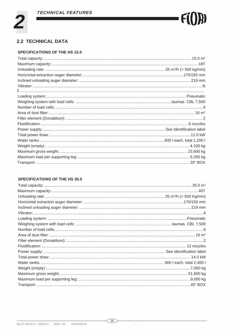
SPECIFICATIONS OF THE HS 15.0 Total capacity: ....................................................................................................................................... 15.0 m3
Maximum capacity: ..................................................................................................................................... 18T Unloading rate: .............................................................................................................25 m3/h (> 500 kg/min) Horizontal extraction auger diameter: ........................................................................................... 170/193 mm Inclined unloading auger diameter: ...................................................................................................... 219 mm Vibrator: ..........................................................................................................................................................N 2 ........................................................................................................................................................................ Loading system: ............................................................................................................................... Pneumatic Weighing system with load cells: .......................................................................................laumas CBL 7,500 Number of load cells: ...................................................................................................................................... 4 Area of dust fi lter: ..................................................................................................................................... 16 m2
Filter element (Donaldson): ............................................................................................................................ 2 Fluidifi cation: ...................................................................................................................................... 6 nozzles Power supply: ...............................................................................................................See Identifi cation label Total power draw: ................................................................................................................................ 11.0 kW Water tanks: ................................................................................................................. 600 l each, total 1,200 l Weight (empty) : ................................................................................................................................. 4.100 kg Maximum gross weight: .................................................................................................................... 23,600 kg Maximum load per supporting leg: ...................................................................................................... 6,200 kg Transport: ........................................................................................................................................... 20” BOX
SPECIFICATIONS OF THE HS 35.0 Total capacity: ...................................................................................................................................... 35.0 m3
Maximum capacity: ..................................................................................................................................... 40T Unloading rate: .............................................................................................................25 m3/h (> 500 Kg/min) Horizontal extraction auger diameter: ...........................................................................................170/193 mm Inclined unloading auger diameter: ......................................................................................................219 mm Vibrator: ...........................................................................................................................................................4 Loading system: ...............................................................................................................................Pneumatic Weighing system with load cells: ....................................................................................... laumas CBL 7,500 Number of load cells: .......................................................................................................................................6 Area of dust fi lter: .................................................................................................................................... 16 m2
Filter element (Donaldson): .............................................................................................................................2 Fluidifi cation: ................................................................................................................................... 12 nozzles Power supply: ............................................................................................................... See Identifi cation label Total power draw: ................................................................................................................................ 14.0 kW Water tanks: ................................................................................................................ 600 l each, total 2,400 l Weight (empty) : ..................................................................................................................................7,050 kg Maximum gross weight: .....................................................................................................................51,600 kg Maximum load per supporting leg: ......................................................................................................9,000 kg Transport: ............................................................................................................................................40” BOX

17id.: SILO HS15.0 - HS35.0 REV. 01 21/04/2016
3SAFETY EQUIPMENT
3.1 GENERAL SAFETY EQUIPMENT
In order to avoid damage and injury as a result of malfunction or operator error, the machine is equipped with numerous safety devices which are calibrated during fi nal testing.
The machine has electrical and mechanical guards and safety devices to ensure operator safety.The following safety devices are generally installed on the machine:- Intrusion guards.- Guards protecting moving parts.- Thermal cutouts.- Alarm lamps, fl ashers and sirens.- Ground circuit for connection to the mains (to be done by the user).
3.2 SAFETY INSTRUCTIONS
The machine is designed and fabricated to conform with the safety requirements of the Machinery Directive; however, during installation, use, cleaning, lubrication and maintenance, general and personal protective equipment must be used, both as indicated in this manual and as required by the special hazards encountered during such work.Always work with appropriate caution and diligence when transporting, assembling, starting up, using, cleaning, lubricating and servicing the machine.
CAUTION: The machine may not be used by UNAUTHORISED PERSONS. Do not allow unauthorised persons to access zones which are closed, fenced off or
marked as dangerous.
- Routine and extraordinary maintenance must be done only by trained MAINTENANCE ELECTRICIANS AND MECHANICS.
- The machine's keys must be kept by the machine's supervisor at all times.- Before doing any maintenance, make sure that the machine is stopped and in the ZERO ENERGY STATE.- After completing maintenance and repairs, make sure that no foreign matter has been left inside the area
affected by the work.- Do not place objects close to the machine.- Do not place objects in areas intended as passageways for staff.
3.1.1 PERSONAL PROTECTIVE EQUIPMENT (PPE)
Wear clothing suited to the work to be carried out on the site and do not wear loose or hanging clothes such as ties, scarves, unbuttoned jackets, unzipped garments or sleeves with wide cuffs, which may get caught up in the moving parts. Do not wear rings, wrist watches or any other jewellery.The following protective clothing is to be worn as prescribed by the site regulations:- Hardhat- Non-slip shoes- Protective goggles- Protective gloves- Anti-noise headsets (where applicable)- Refl ecting garments or vests- Raincoats in bad weather- Protective mask for cement loading
18id.:SILO HS15.0 - HS35.0 REV. 01 21/04/2016
3 SAFETY EQUIPMENT
3.3.1 OBTAINING THE ZERO ENERGY STATE
3.3 ZERO ENERGY STATEThis is the safety condition in which the machine must be set in the following situations:- Malfunction, anomalies or unexpected running noise.- Normal stop, emergency stop and prolonged shutdown.- When cleaning or lubricating the machine.- When running routine or extraordinary maintenance.
1 - Press the EMERGENCY STOP button. A red manual re-arm button is located on the control panel and, depending on the type of machine, may
also be located in other positions of the machine, such as next to the lifters.2 - Disconnect electrical power. Shut off power to the enclosures with the MASTER POWER SWITCH and padlock it in position.3 - Close the pneumatic circuit shut-off valves. To depressurise the pneumatic circuit, open the condensate drain cocks below the main tank. Once the machine is in the ZERO ENERGY STATE, do the scheduled work.To restore normal operation, proceed in the reverse order from the above procedure, from step 3 to step 1
DANGER:
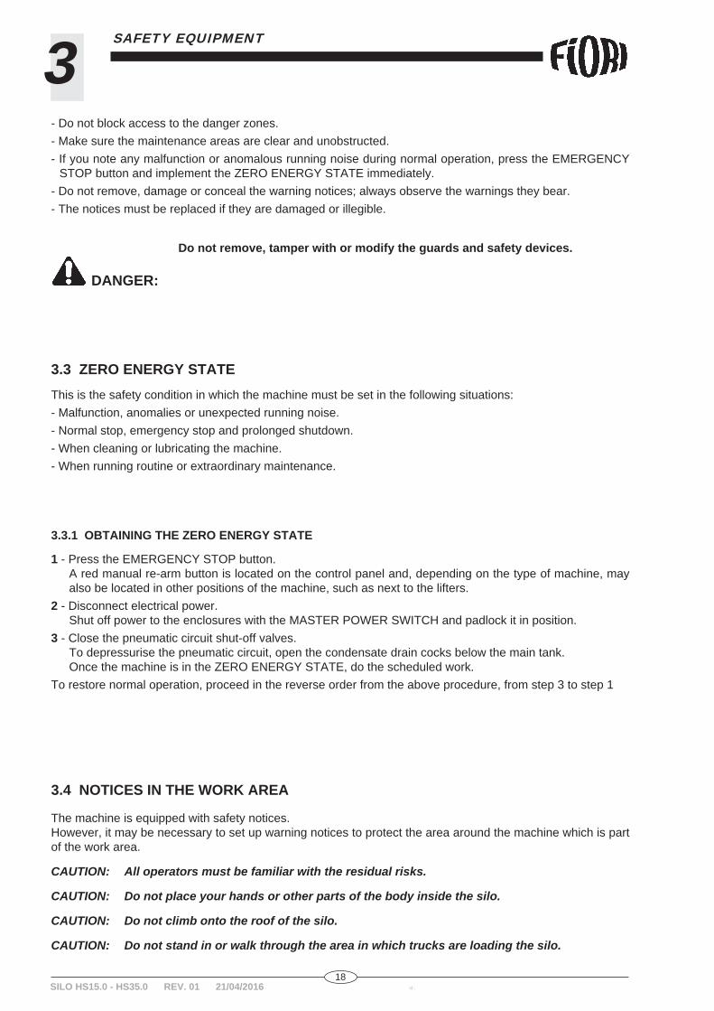
- Do not block access to the danger zones.- Make sure the maintenance areas are clear and unobstructed.- If you note any malfunction or anomalous running noise during normal operation, press the EMERGENCY
STOP button and implement the ZERO ENERGY STATE immediately.- Do not remove, damage or conceal the warning notices; always observe the warnings they bear.- The notices must be replaced if they are damaged or illegible.
Do not remove, tamper with or modify the guards and safety devices.
3.4 NOTICES IN THE WORK AREA
The machine is equipped with safety notices.However, it may be necessary to set up warning notices to protect the area around the machine which is part of the work area.
CAUTION: All operators must be familiar with the residual risks.
CAUTION: Do not place your hands or other parts of the body inside the silo.
CAUTION: Do not climb onto the roof of the silo.
CAUTION: Do not stand in or walk through the area in which trucks are loading the silo.

19id.: SILO HS15.0 - HS35.0 REV. 01 21/04/2016
3SAFETY EQUIPMENT
CAUTION: Do not service or tamper in any way with live electrical equipment without fi rst having set the system to the ZERO ENERGY STATE.
CAUTION: Do not start the fi lter with the inspection hatch open.
CAUTION: DO NOT start the machine unless ALL GUARDS AND PROTECTIVE EQUIPMENT ARE INSTALLED AND OPERATIONAL.
Do not tamper with or partially/fully disable the safety devices; doing so relieves the manufacturer of any responsibility for the consequences.
CAUTION: Check the condition of the safety equipment regularly.
The warning and safety stickers on the machine are guides for your safety and that of anyone working with you. A label is positioned at each part of the vehicle that may be a source of residual risk. Therefore, walk around the vehicle with this manual in hand and familiarise yourself with where the various labels are positioned and read them.However, it may be necessary to set up warning notices to protect the area around the machine which is part of the work area.Go over them with all operating staff and keep them legible; a set of replacement stickers can be requested from our Spare Parts Department if they become illegible.Always keep the labels clean. Use detergent and water to clean the labels. Do not use organic solvents or petrol as they may damage the labels.1 - Wash the stickers with soap and water and dry them off with a soft cloth.2 - Replace any damaged or missing stickers with original replacements.3 - If you have to replace any part bearing stickers, make sure the replacement part bears the same stickers.4 - When replacing the stickers, make sure the surface is clean, dry and free of oil or grease.
CAUTION: The manufacturer declines all responsibility for personal injury or property damage if the rules of conduct indicated on the labels are not observed or the labels are not kept in perfect conditions.
3.4.1 WARNING AND SAFETY STICKERS (RESIDUAL RISKS)
DANGER: Highlights the presence of live electrical equipment.
DANGER: Highlights the presence of components which pose a hazard for the fi ngers and hands.

20id.:SILO HS15.0 - HS35.0 REV. 01 21/04/2016
3 SAFETY EQUIPMENT
For lifting, tying and towing the vehicle, use only the special couplings marked with this symbol.
Read the manual carefully before using or servicing the machine.
Earth connection, indicates where the earth cable is secured to the frame.

21id.: SILO HS15.0 - HS35.0 REV. 01 21/04/2016
4INSTALLATION
SILO HS15.0 - HS35.0 REV. 01 21/04/2016
4.1 PREFACEThe silo is designed to be easy to install and put into operation. Do not install the machine unless you have CAREFULLY AND THOROUGHLY read this manual and under-stood how the machine works as a whole.
CAUTION: The unloading staff must be equipped with all safety and protective equipment required for the task, in particular: helmet, safety boots, protective gloves.
4.2 PRELIMINARY CHECKSBefore installing the machine, run the following checks with the client's technicians:- Check that the clearances, overall dimensions, passageways, gaps (overall envelope) etc. provide for free
movement.- Check that the assembly and installation equipment is present and correct.- Check that the lifting equipment is suited to the job.- Check that the installation staff is suited to the job and adequately experienced.- Check that the air, water and electrical power connections required for the installation are available.- Check that the concrete slab is rated to bear the weight of the silo when full (80 kg/cm2) and is not sloping
more than 2%. If the slab cannot be improved, use accessories to increase the supporting surface.
4.3 UNLOADING AND POSITIONINGWhen the truck arrives on site, the user must prepare an area for installing the silo and unloading all parts, as well as providing the lifting equipment for unloading and positioning it. Loading and unloading must always be done on level ground able to bear the weight of the silo. The maximum permitted slope in any direction is 3%.If the documents required for these tasks are not available, contact the FIORI assistance department for new copies.
CAUTION: The unloading staff must be equipped with all safety and protective equipment required for the task, in particular: helmet, safety boots, protective gloves.
Keep all unauthorised persons out of the unloading area, including the areas required to position the silo and the range of the crane and lifting equipment being used.
Danger of impact and crushing for the operators.
CAUTION: Do not lift parts weighing more than 25 kg by hand; use proper mechanical equipment to do so. Failure to observe this precaution can result in back injury.
CAUTION: Make sure you have suffi cient chains, hooks and straps of the right load rating and length
CAUTION: Do not unload the equipment on sloping or loose ground.
CAUTION: ALWAYS USE ONLY the attachment points specifi ed by the manufacturer.
DANGER:
22id.:SILO HS15.0 - HS35.0 REV. 01 21/04/2016
4 INSTALLATION
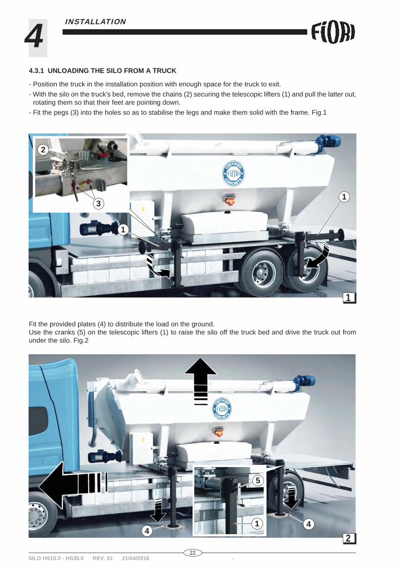
4.3.1 UNLOADING THE SILO FROM A TRUCK
- Position the truck in the installation position with enough space for the truck to exit.- With the silo on the truck's bed, remove the chains (2) securing the telescopic lifters (1) and pull the latter out,
rotating them so that their feet are pointing down.- Fit the pegs (3) into the holes so as to stabilise the legs and make them solid with the frame. Fig.1
Fit the provided plates (4) to distribute the load on the ground.Use the cranks (5) on the telescopic lifters (1) to raise the silo off the truck bed and drive the truck out from under the silo. Fig.2
1
2
2
3
1
1
5
1 44
23id.: SILO HS15.0 - HS35.0 REV. 01 21/04/2016
4INSTALLATION
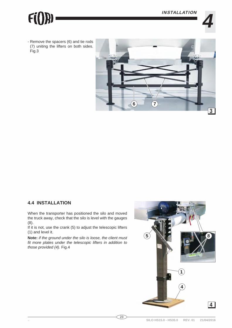
- Remove the spacers (6) and tie rods (7) uniting the lifters on both sides. Fig.3
4.4 INSTALLATION
When the transporter has positioned the silo and moved the truck away, check that the silo is level with the gauges (8).If it is not, use the crank (5) to adjust the telescopic lifters (1) and level it.Note: if the ground under the silo is loose, the client must fi t more plates under the telescopic lifters in addition to those provided (4). Fig.4
8
36 7
5
1
4
4

24id.:SILO HS15.0 - HS35.0 REV. 01 21/04/2016
4 INSTALLATION
SILO HS15.0 - HS35.0 REV. 01 21/04/2016
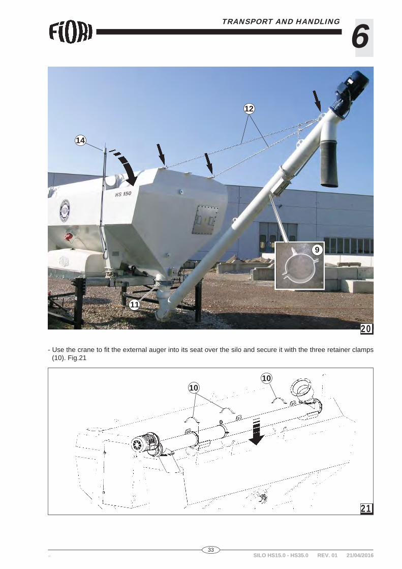
The silo is now ready for the auger to be installed.- Move the movable collar (9) to the sticker with the two arrows indicating the centre of gravity of the assembled
auger. Unbolt and remove the three retaining collars (10) from the auger and use a crane to lift and unload it from the silo. Fig.5
- Fit the rubber boot (15) and secure it with the metal clamp to the auger's cement outlet terminal. Fig.7
- Tilt the auger by around 40° and move it under the butterfl y valve (11).
- Apply a bead of silicone around the auger's fl ange to prevent water entering it and couple it with the butterfl y valve; install and tighten down the provided fasteners. Fig.6
- Position the auger at the height required for unloading, fi x the two chains (12) to the silo, and attach the other two ends of the chain to the auger's eyebolt. Use the turnbuckles (13) to fi nely adjust the height.
- Position the radio modem (14) by rotating its bracket through 90°. Fig.7
9
6
7
15
11
1213
14
5
10
10

25id.: SILO HS15.0 - HS35.0 REV. 01 21/04/2016
4INSTALLATION
- Slacken off the safety nuts (16) so that the top presses (A) against the load cells (17).
After slackening all safety nuts, check manually that the load cell (17) does not move.
If it does move, raise the telescopic lifters until the load cell is locked in place (16). Fig.8
4.5 ELECTRICAL HOOKUP
The electrical connection between the machine's enclosure and the mains power supply must be completed by a qualifi ed electrician, and is to be done by the client.The client must also, and at his own expense, provide a ground circuit in compliance with local regulations.Each machine is tested at the factory and its direction of rotation is marked with arrows. Once the machine has been connected to the mains power supply, check its rotation again.
CAUTION: Not doing so can result in damage to the machine.
The power voltage (1), frequency (2) and maximum power rating (3) are given on the nameplate. Fig.9They may vary within the following limits:+- 10% for Vn+- 1% for f
exceeding this tolerance can damage the machine; the manufacturer is not liable for damage or injury caused by non-observance of this requirement.Characteristics of the power cable:The cross section of the power cable and the protection of the electrical equipment (differential thermal cutout) are the responsibility of the client and must suit the power draw and short circuit current at the point of instal-lation.
16
17
A
8
1 2 93

26id.:SILO HS15.0 - HS35.0 REV. 01 21/04/2016
4 INSTALLATION
Route the three-phase cable through the cable gland in the electrical enclosure wall. Connect the three wires to the fi rst three terminal clamps (1 - U) (2 - V) (3 - W), with the earth wire (yellow-green) connected to the earth terminal clamp (18). Fig.10
4.6 CALIBRATING THE SCALES
The silo is delivered with its scales tested and calibrated with samples. The client is responsible for having the scales properly calibrated by a local qualifi ed agency. To correct defects in the weighing, refer to the user and maintenance manual for the weighing equipment, enclosed with this manual.
CAUTION: This job must be done under the supervision of a FIORI qualifi ed or delegated technician.
18
10

27id.: SILO HS15.0 - HS35.0 REV. 01 21/04/2016
5OPERATION AND USE
5.1 DESCRIPTION OF THE MAIN COMPONENTS Fig.11
12
3
4
4
5
5
5
5
6
6
77
7 7
7
7
8
9
9
10
11
11
12
13
14
15 16
17
18
18
1 - Silo frame2 - Vibrator3 - Control panel4 - Water tank5 - Load cell6 - Lower frame7 - Telescopic lifter8 - Filters9 - Pressure vent valve10 - Inspection hatch
11 - External auger12 - Radio modem13 - Internal auger14 - Rear door15 - Compressor16 - Air tank17 - Butterfl y valve18 - Material loading tube
2
11
28id.:SILO HS15.0 - HS35.0 REV. 01 21/04/2016
5 OPERATION AND USE
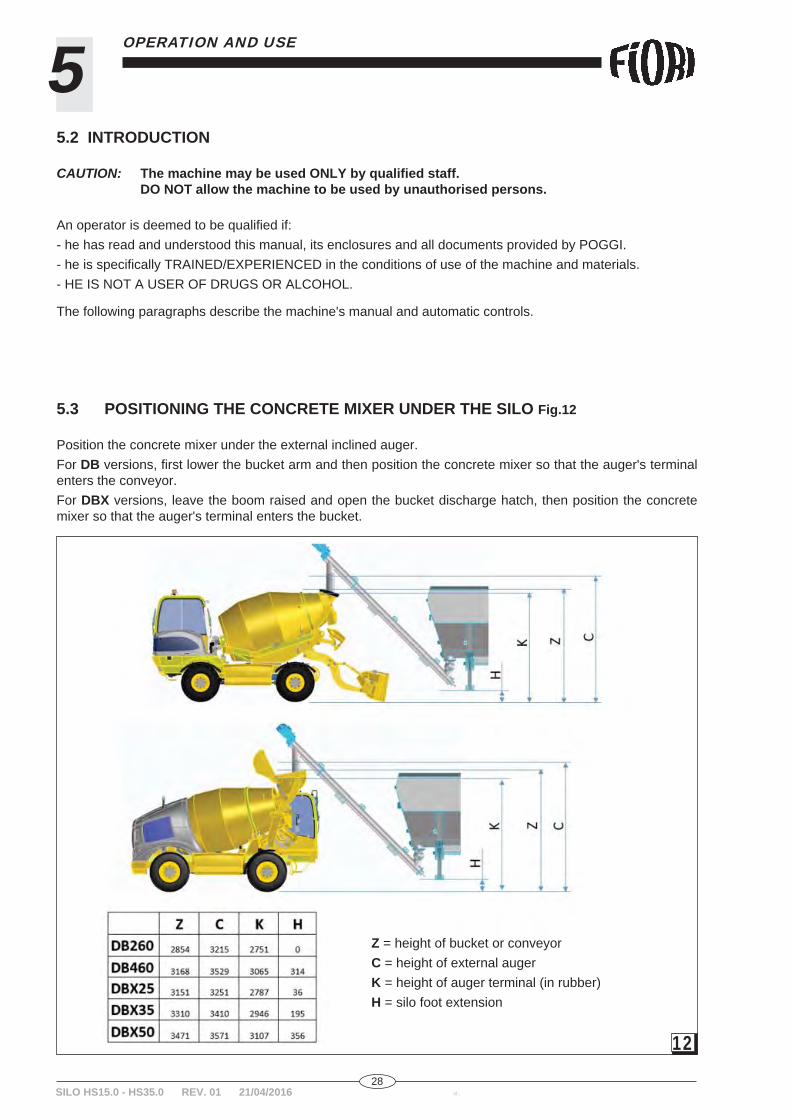
5.3 POSITIONING THE CONCRETE MIXER UNDER THE SILO Fig.12
Position the concrete mixer under the external inclined auger.For DB versions, fi rst lower the bucket arm and then position the concrete mixer so that the auger's terminal enters the conveyor.For DBX versions, leave the boom raised and open the bucket discharge hatch, then position the concrete mixer so that the auger's terminal enters the bucket.
Z = height of bucket or conveyorC = height of external augerK = height of auger terminal (in rubber)H = silo foot extension
5.2 INTRODUCTION
CAUTION: The machine may be used ONLY by qualifi ed staff. DO NOT allow the machine to be used by unauthorised persons.
An operator is deemed to be qualifi ed if:- he has read and understood this manual, its enclosures and all documents provided by POGGI.- he is specifi cally TRAINED/EXPERIENCED in the conditions of use of the machine and materials.- HE IS NOT A USER OF DRUGS OR ALCOHOL.
The following paragraphs describe the machine's manual and automatic controls.
12

29id.: SILO HS15.0 - HS35.0 REV. 01 21/04/2016
5OPERATION AND USE
5.6 AUTOMATIC CONTROL SYSTEM
Turn key switch 3 to AUTO to disable the front panel buttons and enable the remote controls. This means that all controls on the front panel are ignored, except for the vibrator and fi lter cleaning controls. The silo has a switch which sets the RF frequency of communications with the remote control (radio modem).
CAUTION: When the silo is working in automatic mode, it is essential that you maintain a safe distan-ce from it and the machinery working with it.
5.5 MANUAL CONTROL SYSTEM
Turn key switch 3 to MAN to enable the front panel buttons and disable the remote controls. In this mode, all remote controls are ignored. The switch's key must be kept by the machine supervisor and not be made avai-lable to other persons.Use button (5) to start and stop material being unloaded from inside the silo. All operations are controlled di-rectly by the operator. The weighing system displays the weight as it reduces.Button (6) starts the vibrator which helps the material to descend when the silo is almost empty. Excessive use of the vibrator can render the material less fl uid and jam the silo.Switch (7) starts the fi lter cleaning cycle. The fi lter must run throughout the pneumatic loading cycle and runs 5 supplementary cleaning cycles after the switch has been turned to OFF.Lamp (8) indicates that a thermal cutout has tripped to protect the machine. When this happens, check the component which caused the cutout to trip and restore the initial conditions. Resolve the problem and only then press button (9) to re-enable the safety circuit.Button (9) resets all safety devices; if the green lamp is on, the button must be pressed before the panel is ready to operate.There is also an hour meter (10) which indicates how long the silo has been running. This is critical for routine maintenance.
5.4 CONTROL PANEL Fig.13
1 - Master switch 2 - Weighing unit 3 - Manual - automatic 4 - Clean auger 5 - Start - stop 6 - Vibrator 7 - Filter 8 - Thermal cutout 9 - Reset safeties10 - Hour meter11 - Frequency selector
1
3
4
8
9
5 6 2 7
10
11
13
30id.:SILO HS15.0 - HS35.0 REV. 01 21/04/2016
5 OPERATION AND USE
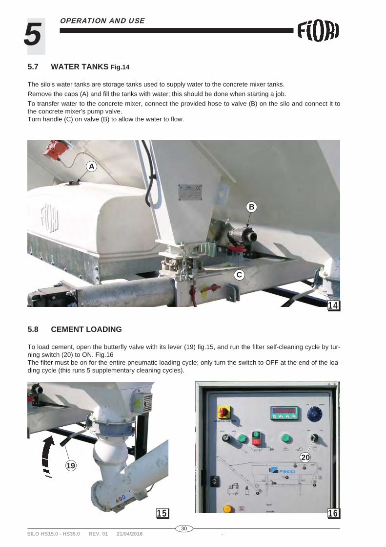
5.7 WATER TANKS Fig.14
The silo's water tanks are storage tanks used to supply water to the concrete mixer tanks.Remove the caps (A) and fi ll the tanks with water; this should be done when starting a job. To transfer water to the concrete mixer, connect the provided hose to valve (B) on the silo and connect it to the concrete mixer's pump valve.Turn handle (C) on valve (B) to allow the water to fl ow.
A
B
C
5.8 CEMENT LOADING
To load cement, open the butterfl y valve with its lever (19) fi g.15, and run the fi lter self-cleaning cycle by tur-ning switch (20) to ON. Fig.16The fi lter must be on for the entire pneumatic loading cycle; only turn the switch to OFF at the end of the loa-ding cycle (this runs 5 supplementary cleaning cycles).
14
19
1615
20

31id.: SILO HS15.0 - HS35.0 REV. 01 21/04/2016
6TRANSPORT AND HANDLING
6.1 TRANSPORT
The machine is assembled and tested by the manufacturer, including its accessories, if any; it is possible that some of these assemblies are removed for transport and require re-assembly on site. The silo is intended to be moved on a truck, and its supports are designed specifi cally for this form of transport; this practical solution enables it to be moved to the work site very quickly.It is very easy to load/unload the silo onto and off the truck bed with the provided lifters.
CAUTION: The silo cannot be moved unless it is completely empty.
6.2 LOADING AND UNLOADING
When the truck arrives on site, the user must prepare an area for installing the silo and unloading all parts, as well as providing the lifting equipment for unloading and positioning it. The truck must be rated for the load and long enough to support the entire silo with its accessories removed.Loading and unloading must always be done on level ground able to bear the weight of the silo. The maximum permitted slope in any direction is 3%.Before loading the silo onto the trailer, remove the inclined auger (if present), completely empty out the silo and disconnect its electrical and other power supplies.If the documents required for these tasks are not available, contact the FIORI assistance department for new copies.
CAUTION: The unloading staff must be equipped with all safety and protective equipment required for the task, in particular: helmet, safety boots, protective gloves.
Keep all unauthorised persons out of the unloading area, including the areas required to position the silo and the range of the crane and lifting equipment being used.
Danger of impact and crushing for the operators.
CAUTION: Do not lift parts weighing more than 25 kg by hand; use proper mechanical equipment to do so. Failure to observe this precaution can result in back injury.
CAUTION: Make sure you have suffi cient chains, hooks and straps of the right load rating and length
CAUTION: Do not unload the equipment on sloping or loose ground.
CAUTION: ALWAYS USE ONLY the attachment points specifi ed by the manufacturer.
DANGER:

32id.:SILO HS15.0 - HS35.0 REV. 01 21/04/2016
6 TRANSPORT AND HANDLING
6.2.1 LOADING THE SILO ONTO A TRUCK
- Drain all the water out of the tanks and empty all cement out of the silo.
Note the instrument panel display (21) will show around 1000 kg, which is the load measured by the cement load cells inside the silo, which cannot be extracted with the au-ger. Fig.17
Disconnect the three wires from the fi rst three terminal clamps (1 - U) (2 - V) (3 - W), and the earth wire (yellow-green) from the earth terminal clamp (18). Extract the three-phase cable from the control enclosure cable gland. Fig.18
- Tighten down the safety nuts (16) so that when it lifts, the top is no longer in contact (A) with the load cells (17). Fig.19
- Position the movable collar (9) around the external auger, hook the crane's chain/rope to the mobile clamp eye bolt.
- Undo all bolts uniting the auger to the butterfl y valve (11).- Release the chains (12) securing the auger to the silo.- Close the radio modem by rotating it through 90° (14). Fig.20
A
18
18
17
19
1617
21
33id.: SILO HS15.0 - HS35.0 REV. 01 21/04/2016
6TRANSPORT AND HANDLING
9
- Use the crane to fi t the external auger into its seat over the silo and secure it with the three retainer clamps (10). Fig.21
12
14
11
20
21
1010
34id.:SILO HS15.0 - HS35.0 REV. 01 21/04/2016
6 TRANSPORT AND HANDLING
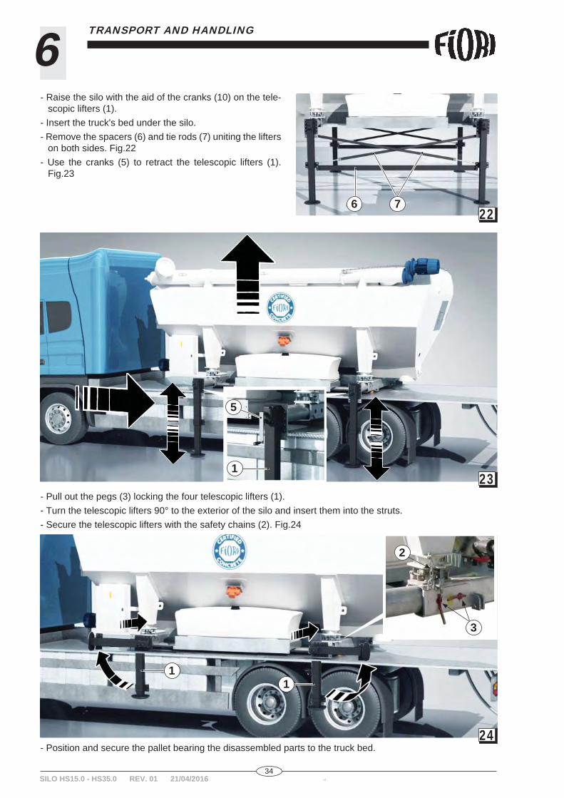
- Raise the silo with the aid of the cranks (10) on the tele-scopic lifters (1).
- Insert the truck's bed under the silo.- Remove the spacers (6) and tie rods (7) uniting the lifters
on both sides. Fig.22- Use the cranks (5) to retract the telescopic lifters (1).
Fig.23
- Pull out the pegs (3) locking the four telescopic lifters (1).- Turn the telescopic lifters 90° to the exterior of the silo and insert them into the struts.- Secure the telescopic lifters with the safety chains (2). Fig.24
- Position and secure the pallet bearing the disassembled parts to the truck bed.
23
24
11
2
3
1
5
2276

35id.: SILO HS15.0 - HS35.0 REV. 01 21/04/2016
6TRANSPORT AND HANDLING
6.3 SPECIAL HANDLING WITH A CRANE
Use a crane capable of bearing the empty weight of the load, see chapter 2.2 TECHNICAL DATA of both silos, and add 1000 kg to allow for any cement remaining inside.To lift the silo, harness it at both attachment points, so that the main hook is attached to both ropes.
25
- Proceed as indicated in par. 6.2.1: empty out the water from the tanks, completely empty out all cement from the silo, disconnect the electrical equipment and release the load cells.
- When you next position the silo, restore the above equipment.

36id.:SILO HS15.0 - HS35.0 REV. 01 21/04/2016
6 TRANSPORT AND HANDLING
6.4 TEMPORARY STORAGE
CAUTION: The silo can be stored only when empty and thoroughly cleaned.
- Protect its parts with polythene sheeting, leaving space for ventilation (the polythene must be of the additivi-sed type, rated to bear changing temperatures, humidity and light without degradation).
- Check the condition of the protection weekly, making sure that the ventilation/drainage opening are not obscured by accidental movement.
- Check the interior of the packaging of material packed in boxes, cages or crates (sheeting, bag, barrier, etc.) and proceed as indicated in the previous point.
- Take special care that the electrical equipment is protected against all forms of humidity.
6.5 COMMISSIONING STORED MATERIAL
After storage, run the following checks before using the material:- Remove the protection and packaging (as applicable), then visually inspect all parts and restore the general
conditions as required;- Check the level of the oil in the gear units and parts protected by grease (bearings, passive supports, etc.)
top up and fi ll with oil and grease as required.
- Hook the crane's chains/ropes to the anchor points on the silo, lift and move it. When placing it on the ground, remember to fi t the plates (4) under the telescopic lifters. Fig.26
26
4
37id.: SILO HS15.0 - HS35.0 REV. 01 21/04/2016
7MAINTENANCE
7.1 OPERATOR QUALIFICATIONS
CAUTION: The machine may be cleaned, lubricated and serviced ONLY by qualifi ed service staff. NEVER allow unauthorised persons to do these jobs.
A maintenance technician is considered to be qualifi ed when he possesses the requisites indicated in par. 6.2.The maintenance technician must also have REAL TRAINING/EXPERIENCE with the machine and its mainte-nance procedures to be able to check the operation of the machine and take corrective action when necessary.
In particular, the maintenance technician must be familiar with:- The mechanical and electrical safety devices- The electrical equipment and circuits- The safety devices and their alarms.- The adjustment, calibration and troubleshooting procedures, to restore normal operation.
Maintenance staff must also be able to:- Check and adjust mechanisms and components.- Check the operation of the movements and adjust the safety devices.- Replace mechanical and electrical components and the machine's safety devices.- Work on the electrical equipment with reference to the hookup diagram.- Replace mechanical and electrical components as part of extraordinary maintenance.- Do mechanical adjustments, calibrate and test the machine.- Check the condition of the bolted and welded couplings.- Check the condition and level of lubricants, in awareness of their polluting nature and hazardousness.- Draw up a maintenance and test report in the calibration logbook.
The machine's supervisor is responsible for identifying and qualifying the MAINTENANCE TECHNICIAN char-ged with cleaning, lubricating and servicing the machine.Given the working conditions and the abrasive and corrosive nature of the materials, the machine must be CLEANED, LUBRICATED AND SERVICED at the times and in the manner indicated in this chapter to ensure a long, effi cient working life.We advise using a log sheet to log these jobs.The silo is not generally prone to malfunction, however should any operational defects arise, contact FIORI assistance, not a third party service contractor.
7.2 ROUTINE AND EXTRAORDINARY MAINTENANCE
To keep the silo in excellent working order, run the scheduled checks and service work given in the ROUTINE MAINTENANCE SCHEDULE in Chapter 7.5; along with the following supplementary checks:
Routine maintenance:To keep the silo in excellent working order, run the scheduled checks and service work given below:- Regularly check the silo's housing for CRACKS.- Once a year, check that all bolts on the housing are tight and torque them if necessary.
- Check that all documents and the notices on the silo and its vicinity are legible.
Every 5 years, open all the silo's hatches to air out its interior and then, wearing the PPE indicated in par. 3.1.1 and required by local regulations, with the silo made safe as indicated in Chapters 3.2 and 3.3, clean and check all its rotating internal parts.

38id.:SILO HS15.0 - HS35.0 REV. 01 21/04/2016
7 MAINTENANCE
NEVER ENTER THE SILO IF IT IS NOT COMPLETELY EMPTY OR WITHOUT THE REGULATORY PPE!!!.
Any repairs to the silo must be done by specialised technicians using original spare parts supplied by POGGI.
Extraordinary maintenance:Extraordinary maintenance includes all work needing to be done in response to:- Faults caused by failure to do routine maintenance properly and as scheduled.- Faults caused by failure to clean, lubricate and grease the machine properly.- Work to be done at relatively long intervals, corresponding to the service life of major assemblies or compo-
nents.- Work requiring a long period of downtime (more than one working day).
DANGER:
7.3 ADJUSTING THE MACHINE
The silo is delivered already adjusted for the product specifi ed in the order, however it can be adjusted by a qualifi ed technician, following a safety shutdown in observance of all the rules mentioned above.
- Check that the silo is always aligned or level; loose ground under it may cause it to slip out of level, as can rain.
- The silo must be set to the zero energy state.- If you have to enter the silo, it must be completely empty and well ventilated.- Wear all appropriate and regulatory PPE.- All further safety devices required by the circumstances.
7.3.1 ADJUSTING THE FLUIDIFICATION PRESSUREFig.27
- Remove the plate supply line and cap it.- Press the red button on the solenoid valve to enable the air fl ow.- Read the pressure off the pressure gauge; the optimum setting is 0.9
bar, but it can be increased to as much as 1.3 bar if necessary.
If this adjustment does not improve performance as expected, contact FIORI assistance immediately for fur-ther instructions.
SILO HS15.0 - HS35.0 REV. 01 21/04/2016
27

39id.: SILO HS15.0 - HS35.0 REV. 01 21/04/2016
7MAINTENANCE
7.3.2 ADJUSTING THE INTERNAL AUGER SHUTTERS Fig.28
CAUTION: This must be done only by experienced and properly qualifi ed staff.
CAUTION: Before entering the silo, make sure that all local regulations governing the situation have been observed.
- Open the silo's rear door (22) and the hatches (23) on the channel to provide proper internal ventilation. - Lower the shutters (24) in areas where the material is running too fast and creating air gaps.- Raise the shutters if there are areas in which the silo is unable to unload the product and deposits are forming.- Fully tighten down the fasteners on the shutters.- Clean the door closing area thoroughly. Apply a uniform bead of silicone around the edge of the door (14)
making sure to run it close to the fasteners. We advise replacing the nuts and washers to avoid problems. Tighten all nuts fully down.
7.3.3 ADJUSTING THE REGULATOR VIBRATING BODIES Fig.29
CAUTION: All vibrators are supplied properly adjusted by the manufacturer. This must be done only by experienced and properly qualifi ed staff.
- Slacken off the bolts securing the vibrator side covers.- Slacken off the central nut on both sides.- Rotate the moving body around the fi xed body on side of the vibrator
and tighten it fully down.- Locate the second mobile body in the same position as the fi rst and
tighten it fully down.- Restore the side covers.
7.4 DISPOSAL
The product and its components must be sorted by type of material or waste for disposal, as required by EC regulations if disposed of within the EU or local regulations if disposed of elsewhere.
2224
23
24
28
29
40id.:SILO HS15.0 - HS35.0 REV. 01 21/04/2016
7 MAINTENANCE
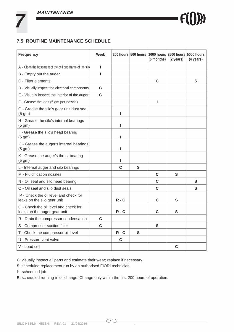
7.5 ROUTINE MAINTENANCE SCHEDULE
Frequency Week 200 hours 500 hours 1000 hours 2500 hours 5000 hours (6 months) (2 years) (4 years)
A - Clean the basement of the cell and frame of the silo I
B - Empty out the auger I
C - Filter elements C S
D - Visually inspect the electrical components C
E - Visually inspect the interior of the auger C
F - Grease the legs (5 gm per nozzle) I
G - Grease the silo's gear unit dust seal (5 gm) I
H - Grease the silo's internal bearings (5 gm) I
I - Grease the silo's head bearing (5 gm) I
J - Grease the auger's internal bearings (5 gm) I
K - Grease the auger's thrust bearing (5 gm) I
L - Internal auger and silo bearings C S
M - Fluidifi cation nozzles C S
N - Oil seal and silo head bearing C S
O - Oil seal and silo dust seals C S
P - Check the oil level and check for leaks on the silo gear unit R - C C S
Q - Check the oil level and check for leaks on the auger gear unit R - C C S
R - Drain the compressor condensation C
S - Compressor suction fi lter C S
T - Check the compressor oil level R - C S
U - Pressure vent valve C
V - Load cell C
C: visually inspect all parts and estimate their wear; replace if necessary.S: scheduled replacement run by an authorised FIORI technician. I: scheduled job.R: scheduled running-in oil change. Change only within the fi rst 200 hours of operation.
SILO HS15.0 - HS35.0 REV. 01 21/04/2016
41id.: SILO HS15.0 - HS35.0 REV. 01 21/04/2016
7MAINTENANCE
7.6 OILS
SILO GEAR UNIT AUGER GEAR UNIT COMPRESSOR
TYPE QUANTITY TYPE QUANTITY TYPE
Fuchs Renolin 1.1 litres Fuchs Renolin 1.0 litres BP Visco 500 5W-30 unysyn CKL 150 CKC 220 Acea A3/BA API SL/CF
The mean air consumption for the fi lter is 5Nm3/h. Any modifi cation can seriously damage the fi lter system and compressor and void the warranty.
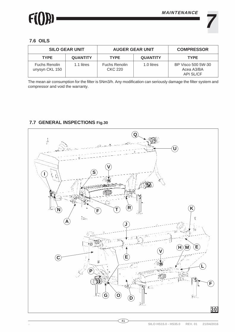
7.7 GENERAL INSPECTIONS Fig.30
C
A
D
L
F
F
G
H M
I
E
E
J
KN
O
P
Q
RT
S
U
V
V
30
42id.:SILO HS15.0 - HS35.0 REV. 01 21/04/2016
7 MAINTENANCE
A - Clean the basement of the cell and frame of the siloClean the silo's entire frame, with special attention to the load cells.
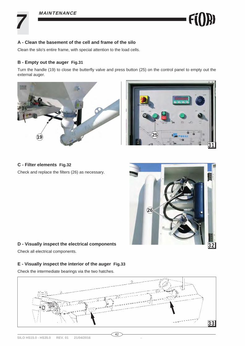
B - Empty out the auger Fig.31
Turn the handle (19) to close the butterfl y valve and press button (25) on the control panel to empty out the external auger.
C - Filter elements Fig.32
Check and replace the fi lters (26) as necessary.
D - Visually inspect the electrical componentsCheck all electrical components.
E - Visually inspect the interior of the auger Fig.33
Check the intermediate bearings via the two hatches.
31
32
33
19
26
25

43id.: SILO HS15.0 - HS35.0 REV. 01 21/04/2016
7MAINTENANCE
F - Grease the legs Fig.34
G - Grease the silo's gear unit dust seal Fig.35
H - Grease the silo's internal bearings Fig.36
I - Grease the silo's head bearing Fig.37
34
35
36
37

44id.:SILO HS15.0 - HS35.0 REV. 01 21/04/2016
7 MAINTENANCE
J - Grease the auger's internal bearings Fig.38
K - Grease the auger's thrust bearing Fig.39
L - Auger and silo internal bearings Fig.40
Open the hatch to check the bearings.
M - Fluidifi cation nozzles Fig.41
38
39
40
41
45id.: SILO HS15.0 - HS35.0 REV. 01 21/04/2016
7MAINTENANCE
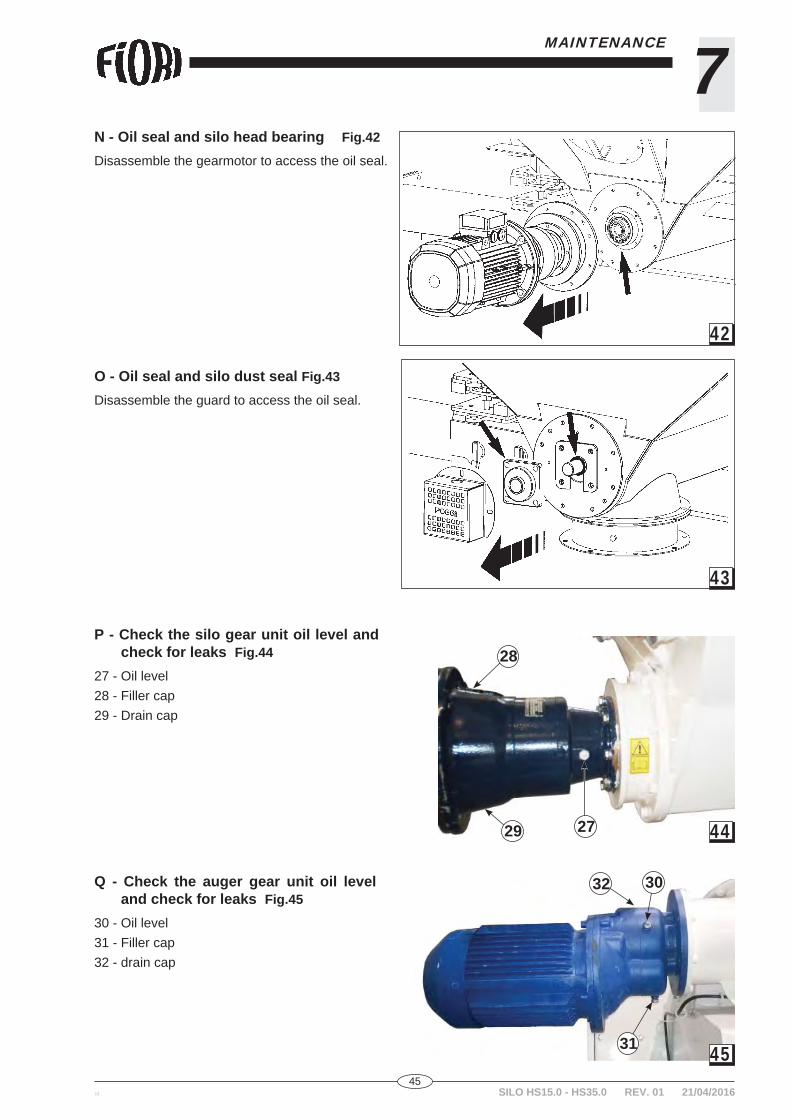
N - Oil seal and silo head bearing Fig.42
Disassemble the gearmotor to access the oil seal.
O - Oil seal and silo dust seal Fig.43
Disassemble the guard to access the oil seal.
P - Check the silo gear unit oil level and check for leaks Fig.44
27 - Oil level28 - Filler cap29 - Drain cap
Q - Check the auger gear unit oil level and check for leaks Fig.45
30 - Oil level31 - Filler cap32 - drain cap
42
43
44
45
27
28
29
30
31
32
46id.:SILO HS15.0 - HS35.0 REV. 01 21/04/2016
7 MAINTENANCE
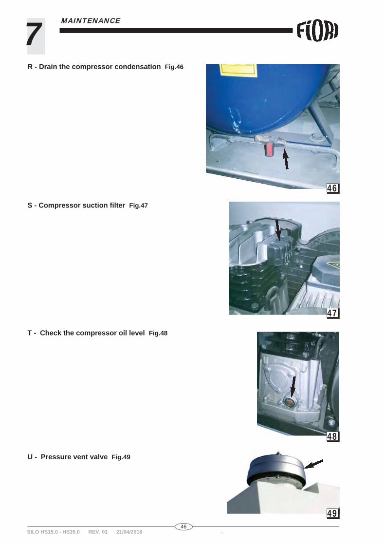
R - Drain the compressor condensation Fig.46
S - Compressor suction fi lter Fig.47
T - Check the compressor oil level Fig.48
U - Pressure vent valve Fig.49
46
47
48
49
47id.: SILO HS15.0 - HS35.0 REV. 01 21/04/2016
7MAINTENANCE
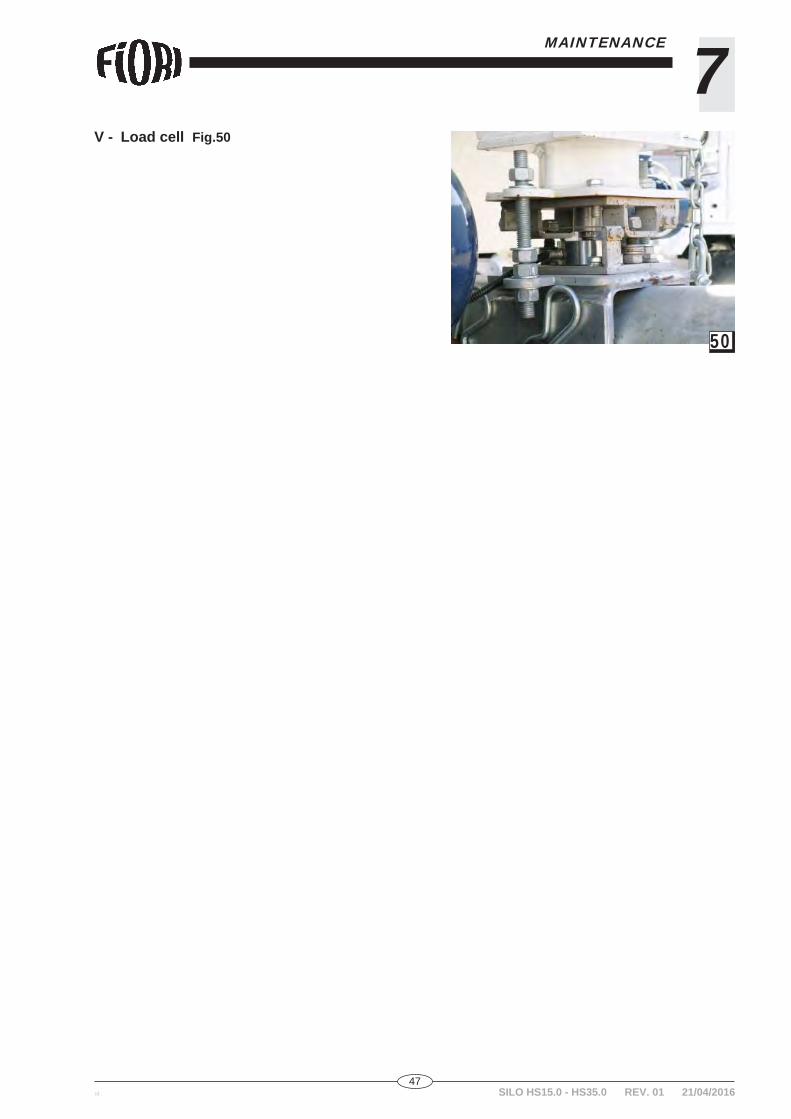
V - Load cell Fig.50
50


RO
UTI
NE
MA
INTE
NA
NC
E
JOB
H
OU
RS:
da
te:
HO
UR
S:
date
: H
OU
RS:
da
te:
O
pera
tor:
O
pera
tor:
O
pera
tor:
R
ESU
LT
RES
ULT
R
ESU
LT- C
lean
the
base
men
t of t
he c
ell a
nd fr
ame
of th
e si
loE
mpt
y ou
t the
aug
er
Fi
lter e
lem
ents
V
isua
lly in
spec
t the
ele
ctric
al c
ompo
nent
s
Vis
ually
insp
ect t
he in
terio
r of t
he a
uger
G
reas
e th
e le
gs (5
gm
per
noz
zle)
G
reas
e th
e si
lo's
gea
r uni
t dus
t sea
l
Gre
ase
the
silo
's in
tern
al b
earin
gs
Gre
ase
the
silo
's h
ead
bear
ing
Gre
ase
the
auge
r's in
tern
al b
earin
gs
G
reas
e th
e au
ger's
thru
st b
earin
g
In
tern
al a
uger
and
silo
bea
rings
Fl
uidi
fi cat
ion
nozz
les
S
ilo o
il se
al a
nd h
ead
bear
ing
Silo
oil
seal
and
gea
r uni
t dus
t sea
l C
heck
the
silo
gea
r uni
t oil
leve
l and
che
ck fo
r lea
ks
Che
ck th
e au
ger g
ear u
nit o
il le
vel a
nd c
heck
for l
eaks
D
rain
the
com
pres
sor c
onde
nsat
ion
Com
pres
sor s
uctio
n fi l
ter
- C
heck
the
com
pres
sor o
il le
vel
- Pre
ssur
e ve
nt v
alve
Load
cel
l
N
ext s
ched
uled
tim
e:
Nex
t sch
edul
ed ti
me:
N
ext s
ched
uled
tim
e:
Not
es:
Not
es:
Not
es:
Not
es:
o
k
n
o
ok
no
o
k
n
o
ok
no
o
k
n
o
ok
no
o
k
n
o
ok
no
o
k
n
o
ok
no
o
k
n
o
ok
no
o
k
n
o
ok
no
o
k
n
o
ok
no
o
k
n
o
ok
no
o
k
n
o
ok
no
o
k
n
o
ok
no
o
k
n
o
ok
no
o
k
n
o
o
k
n
o
ok
no
o
k
n
o
ok
no
o
k
n
o
ok
no
o
k
n
o
ok
no
o
k
n
o
ok
no
o
k
n
o
ok
no
o
k
n
o
ok
no
o
k
n
o
ok
no
o
k
n
o
ok
no
o
k
n
o
ok
no
o
k
n
o
ok
no
o
k
n
o
ok
no
o
k
n
o
o
k
n
o
ok
no
o
k
n
o
ok
no
o
k
n
o
ok
no
o
k
n
o
ok
no
o
k
n
o
ok
no
o
k
n
o
ok
no
o
k
n
o
ok
no
o
k
n
o
ok
no
o
k
n
o
ok
no
o
k
n
o
ok
no
o
k
n
o
ok
no
o
k
n
o
ok
no
o
k
n
o


![Bloodlust [Rev01]](https://img.pdfslide.us/doc/110x75/577cc6021a28aba7119d7bc9/bloodlust-rev01.jpg)