Embed Size (px)
Citation preview

HUBBELL
Silicon ControlledRectifier
4922c Instruction Manual
Publication 189 SCRMarch 1995
JPS-395-0M © 1995Printed in U.S.A.
HubbellIndustrial
Controls, Inc.a subsidiary of Hubbell Inc.4301 Cheyenne DriveArchdale, NC 27282
(336) 434-2800Fax (336) 434-2803
HUBBELLGeneral Description 22
Silicon Controlled RectifiersSection Contents
GeneralDescription .............. 2
GeneralComponents ............ 3
Troubleshooting ........ 4
Silicon Controlled Rectifiers – SCRs
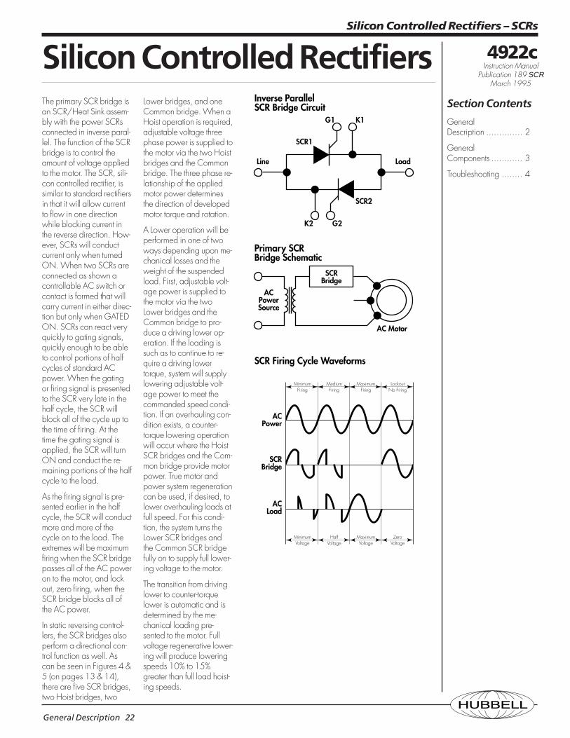
The primary SCR bridge isan SCR/Heat Sink assem-bly with the power SCRsconnected in inverse paral-lel. The function of the SCRbridge is to control theamount of voltage appliedto the motor. The SCR, sili-con controlled rectifier, issimilar to standard rectifiersin that it will allow currentto flow in one directionwhile blocking current inthe reverse direction. How-ever, SCRs will conductcurrent only when turnedON. When two SCRs areconnected as shown acontrollable AC switch orcontact is formed that willcarry current in either direc-tion but only when GATEDON. SCRs can react veryquickly to gating signals,quickly enough to be ableto control portions of halfcycles of standard ACpower. When the gatingor firing signal is presentedto the SCR very late in thehalf cycle, the SCR willblock all of the cycle up tothe time of firing. At thetime the gating signal isapplied, the SCR will turnON and conduct the re-maining portions of the halfcycle to the load.
As the firing signal is pre-sented earlier in the halfcycle, the SCR will conductmore and more of thecycle on to the load. Theextremes will be maximumfiring when the SCR bridgepasses all of the AC poweron to the motor, and lockout, zero firing, when theSCR bridge blocks all ofthe AC power.
In static reversing control-lers, the SCR bridges alsoperform a directional con-trol function as well. Ascan be seen in Figures 4 &5 (on pages 13 & 14),there are five SCR bridges,two Hoist bridges, two
Lower bridges, and oneCommon bridge. When aHoist operation is required,adjustable voltage threephase power is supplied tothe motor via the two Hoistbridges and the Commonbridge. The three phase re-lationship of the appliedmotor power determinesthe direction of developedmotor torque and rotation.
A Lower operation will beperformed in one of twoways depending upon me-chanical losses and theweight of the suspendedload. First, adjustable volt-age power is supplied tothe motor via the twoLower bridges and theCommon bridge to pro-duce a driving lower op-eration. If the loading issuch as to continue to re-quire a driving lowertorque, system will supplylowering adjustable volt-age power to meet thecommanded speed condi-tion. If an overhauling con-dition exists, a counter-torque lowering operationwill occur where the HoistSCR bridges and the Com-mon bridge provide motorpower. True motor andpower system regenerationcan be used, if desired, tolower overhauling loads atfull speed. For this condi-tion, the system turns theLower SCR bridges andthe Common SCR bridgefully on to supply full lower-ing voltage to the motor.
The transition from drivinglower to counter-torquelower is automatic and isdetermined by the me-chanical loading pre-sented to the motor. Fullvoltage regenerative lower-ing will produce loweringspeeds 10% to 15%greater than full load hoist-ing speeds.
SCR1
Line Load
SCRBridge
ACPowerSource
AC Motor
Inverse ParallelSCR Bridge Circuit
Primary SCRBridge Schematic
SCR2
K1G1
K2 G2
ACPower
SCRBridge
ACLoad
SCR Firing Cycle Waveforms
MinimumFiring
MediumFiring
MaximumFiring
LockoutNo Firing
MinimumVoltage
HalfVoltage
MaximumVoltage
ZeroVoltage
4922c Instruction Manual
Publication 189 SCRMarch 1995
HUBBELLMajor Components 23
Silicon Controlled Rectifiers – SCRs
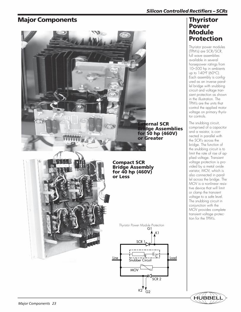
ThyristorPowerModuleProtectionThyristor power modules(TPM’s) are SCR/SCR,full wave assembliesavailable in severalhorsepower ratings from10–500 hp in ambientsup to 140°F (60°C).Each assembly is config-ured as an inverse paral-lel bridge with snubbingcircuit and voltage tran-sient protection as shownin the illustration. TheTPM’s are the units thatcontrol the applied motorvoltage on primary thyris-tor controls.
The snubbing circuit,comprised of a capacitorand a resistor, is con-nected in parallel withthe SCR’s across thebridge. The function ofthe snubbing circuit is tolimit the rate of rise of ap-plied voltage. Transientvoltage protection is pro-vided by a metal oxidevaristor, MOV, which isalso connected in paral-lel across the bridge. TheMOV is a nonlinear resis-tive device that will limitor clamp the transientvoltage to a safe level.The snubbing circuit inconjunction with theMOV provides completetransient voltage protec-tion for the TPM’s.
Major Components
Compact SCRBridge Assemblyfor 40 hp (460V)or Less
Thyristor Power Module Protection
SCR 2
MOV
RSnubber Circuit
C
G2K2
SCR 1
G1K1
Line Load
External SCRBridge Assembliesfor 50 hp (460V)or Greater
HUBBELLTroubleshooting 24
Silicon Controlled Rectifiers – SCRs
TroubleshootingInverse parallel SCRbridges control ACpower by providing amethod of adjusting ap-plied voltage as in thecase of Primary MotorControl. The AC Power ishandled on a half cyclebasis by one of twoSCR’s. Refer to the Pri-mary SCR Bridge figureprovided. SCR1 can con-duct power on the firsthalf of the cycle andSCR2 can conduct duringthe remaining half of thecycle thereby providingbalanced currents. Am-meter readings of motorprimary currents at lowmotor speeds should pro-duce balanced readings.
If one of the SCR’s fails toconduct, the controlledpower becomes unbal-anced with a DC compo-nent which can saturatecommon motor loads andlead to higher than nor-mal operating currents. Ifone of the SCR’s be-comes shorted, the SCRBridge supplies full con-duction for that phase re-sulting in unbalancedphase voltages and cur-rents in Primary Control.
The operating conditionof an inverse parallel SCRBridge can be deter-mined easily with a digi-tal DVM. A simple conti-nuity test can beperformed with the powerremoved from the motorcircuit. In most PrimaryControl systems, when thepower is removed andthe directional or maincontactor is open, theSCR Bridge is isolatedand continuity measure-ments can be made di-rectly at the bridge. Ashorted SCR will result ina very low or “Zero”
ohmmeter reading. Agood SCR Bridge will re-sult in a ohmmeter read-ing of 200K to 300Kohms.
An open or nonconduct-ing SCR as well as ashorted SCR can also belocated by taking a set ofAC and DC readingsacross each SCR Bridgeand comparing the val-ues. Again, normal read-ings will be balancedfrom phase to phase withthe “odd” reading indi-cating a problem. Bylooking at the SCR Bridgewaveforms on the figuressupplied, normal opera-tion is indicated by equalperiods of positive andnegative voltage. Withthe motor operating atminimum speed, approxi-mately 50% voltage willbe supported acrosseach SCR Bridge, and anAC measurement acrosseach bridge should yieldbalanced voltages. A“Zero” or very low ACvoltage reading indicatesa shorted SCR. With theDVM set to read DC, volt-age measurements acrosseach bridge should yielda low DC value indicat-ing equal periods of posi-tive and negative volt-age. A typical DCvoltage encountered inthis measurement will beless than 10 volts. Areading substantiallyhigher than 10 volts indi-cates unbalanced firing.The unbalanced condi-tion will affect the read-ings on the remaining twophases, therefore, thehighest unbalanced volt-age when compared tothe remaining readings,indicates the problemphase.
AC Power
SCR Bridge
AC Load
SCR Firing Cycle Waveforms
MinimumFiring
MediumFiring
MaximumFiring
LockoutNo Firing
MinimumVoltage
HalfVoltage
MaximumVoltage
ZeroVoltage
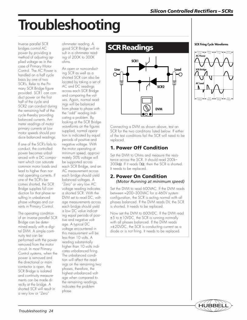
SCR Readings
SCR1
Line Load
SCR2
DVM
Connecting a DVM as shown above, test anSCR for the two conditions listed below. If eitherof the test conditions fail the SCR will need to bereplaced.
1. Power Off ConditionSet the DVM to Ohms and measure the resis-tance across the SCR. It should read 200k–300kΩ. If it reads 0Ω, then the SCR is shorted.It needs to be replaced.
2. Power On Condition (Motor Running at minimum speed)
Set the DVM to read 600VAC. If the DVM readsbetween ≈200–300VAC for a 460V systemconfiguration, the SCR is acting normal with allphases balanced. If the DVM reads 0V, the SCRis shorted. It needs to be replaced.
Now set the DVM to 600VDC. If the DVM read±5 to ±10VDC, the SCR is running normallywith all phases balanced. If the DVM reads>±20VDC, the SCR is conducting current as adiode or is not firing. It needs to be replaced.