Embed Size (px)
Citation preview
Silent conveying chains
FOR IMP ROV ED HANDL ING AND P E R FORMANCE
Ramsey ProductsCorporation
Silent Conveying Chains
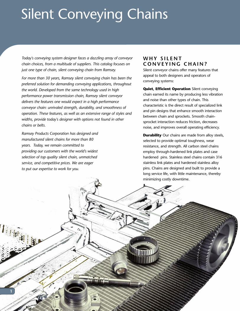
WHY S I L ENT CONVEY ING CHA IN ? Silent conveyor chains offer many features thatappeal to both designers and operators ofconveying systems:
Quiet, Efficient Operation Silent conveyingchain earned its name by producing less vibrationand noise than other types of chain. Thischaracteristic is the direct result of specialized linkand pin designs that enhance smooth interactionbetween chain and sprockets. Smooth chain-sprocket interaction reduces friction, decreasesnoise, and improves overall operating efficiency.
Durability Our chains are made from alloy steels,selected to provide optimal toughness, wearresistance, and strength. All carbon steel chainsemploy through-hardened link plates and casehardened pins. Stainless steel chains contain 316stainless link plates and hardened stainless alloypins. Chains are designed and built to provide along service life, with little maintenance, therebyminimizing costly downtime.
Today's conveying system designer faces a dazzling array of conveyor
chain choices, from a multitude of suppliers. This catalog focuses on
just one type of chain, silent conveying chain from Ramsey.
For more than 30 years, Ramsey silent conveying chain has been the
preferred solution for demanding conveying applications, throughout
the world. Developed from the same technology used in high
performance power transmission chain, Ramsey silent conveyor
delivers the features one would expect in a high performance
conveyor chain: unrivaled strength, durability, and smoothness of
operation. These features, as well as an extensive range of styles and
widths, provide today's designer with options not found in other
chains or belts.
Ramsey Products Corporation has designed and
manufactured silent chains for more than 80
years. Today, we remain committed to
providing our customers with the world's widest
selection of top quality silent chain, unmatched
service, and competitive prices. We are eager
to put our expertise to work for you.
1
2
CONTENTS
A Flat, Uniform Conveying Surface The pinsand links used in Ramsey chains are manufacturedto exacting tolerances. This ensures that conveyorchains have a uniform height and a flat conveyingsurface. Consistent conveyor height enhances thesmooth transport of articles on and off theconveyor, and minimizes tipping.
Nearly constant surface velocity. Throughoutthe production process, we carefully control thepitch of all conveying chains. Controlling the pitchensures consistent surface velocity in each chain.Uniform surface velocity reduces the occurrence ofirregular article spacing, misfeeds, and associatedproblems. Also, since batch-to-batch variations areheld to a minimum, chain from differentproduction batches can be connected withoutsignificant speed variation.
Open, Laced, construction . Silent conveyorchains are typically composed of multiple rows ofstacked, alternating, link plates. The spacebetween alternating rows of links allows air andother fluids to pass through the chain, therebypromoting product drying or cooling. Interlinkspaces also prevent surface debris accumulation byallowing small objects to fall through the chain.Spacers are often used between rows of links tofurther increase the open area and reduce overallchain weight.
Economical, Low Maintenance, Operation.Ramsey silent conveyor chain will often run foryears with little or no lubrication andmaintenance. Extended life and reducedmaintenance translates into reduced downtime andlower life cycle cost.
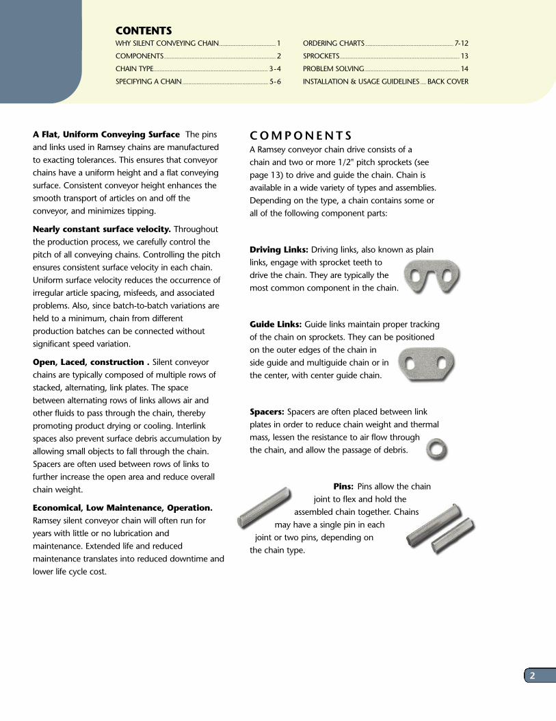
COMPONENTS A Ramsey conveyor chain drive consists of achain and two or more 1/2" pitch sprockets (seepage 13) to drive and guide the chain. Chain isavailable in a wide variety of types and assemblies.Depending on the type, a chain contains some orall of the following component parts:
Driving Links: Driving links, also known as plainlinks, engage with sprocket teeth todrive the chain. They are typically themost common component in the chain.
Guide Links: Guide links maintain proper trackingof the chain on sprockets. They can be positionedon the outer edges of the chain inside guide and multiguide chain or inthe center, with center guide chain.
Spacers: Spacers are often placed between linkplates in order to reduce chain weight and thermalmass, lessen the resistance to air flow throughthe chain, and allow the passage of debris.
Pins: Pins allow the chainjoint to flex and hold the
assembled chain together. Chainsmay have a single pin in each
joint or two pins, depending onthe chain type.
WHY SILENT CONVEYING CHAIN................................................ 1
COMPONENTS............................................................................................... 2
CHAIN TYPE................................................................................................. 3-4
SPECIFYING A CHAIN......................................................................... 5-6
ORDERING CHARTS........................................................................... 7-12
SPROCKETS...................................................................................................... 13
PROBLEM SOLVING................................................................................. 14
INSTALLATION & USAGE GUIDELINES..... BACK COVER
3
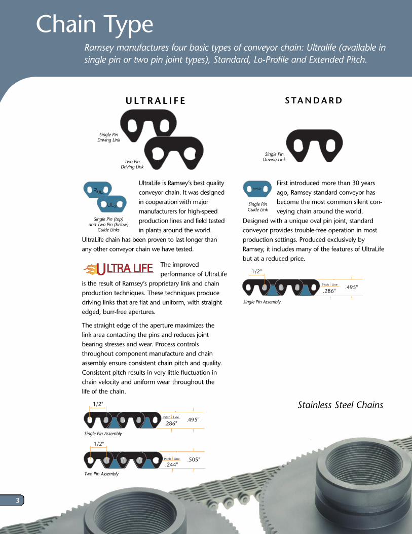
First introduced more than 30 yearsago, Ramsey standard conveyor hasbecome the most common silent con-veying chain around the world.
Designed with a unique oval pin joint, standardconveyor provides trouble-free operation in mostproduction settings. Produced exclusively byRamsey, it includes many of the features of UltraLifebut at a reduced price.
L
1/2"
Pitch Line
.286".495"
UltraLife is Ramsey’s best qualityconveyor chain. It was designedin cooperation with majormanufacturers for high-speed production lines and field tested in plants around the world.
UltraLife chain has been proven to last longer thanany other conveyor chain we have tested.
The improvedperformance of UltraLife
is the result of Ramsey’s proprietary link and chainproduction techniques. These techniques producedriving links that are flat and uniform, with straight-edged, burr-free apertures.
The straight edge of the aperture maximizes the link area contacting the pins and reduces jointbearing stresses and wear. Process controlsthroughout component manufacture and chainassembly ensure consistent chain pitch and quality.Consistent pitch results in very little fluctuation inchain velocity and uniform wear throughout the life of the chain.
1/2"
Pitch Line
.286".495"
Ramsey manufactures four basic types of conveyor chain: Ultralife (available insingle pin or two pin joint types), Standard, Lo-Profile and Extended Pitch.
Chain Type
STANDARD U LTRA L I F E
Single Pin Driving Link
Single Pin Guide Link
Single Pin Driving LinkTwo Pin
Driving Link
Single Pin Assembly
Two Pin Assembly
Single Pin Assembly
Single Pin (top) and Two Pin (below)
Guide Links
1/2"
Pitch Line
.244".505"
Stainless Steel Chains
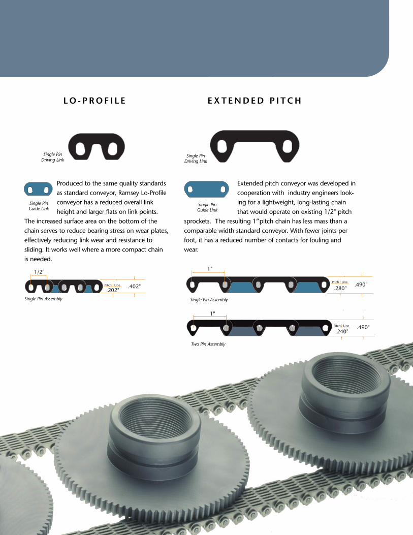
Produced to the same quality standardsas standard conveyor, Ramsey Lo-Profileconveyor has a reduced overall linkheight and larger flats on link points.
The increased surface area on the bottom of thechain serves to reduce bearing stress on wear plates,effectively reducing link wear and resistance to sliding. It works well where a more compact chainis needed.
1/2"
Pitch Line
.202".402"
Extended pitch conveyor was developed incooperation with industry engineers look-ing for a lightweight, long-lasting chainthat would operate on existing 1/2" pitch
sprockets. The resulting 1” pitch chain has less mass than acomparable width standard conveyor. With fewer joints perfoot, it has a reduced number of contacts for fouling andwear.
L
LO - PROF I L E EXT ENDED P I TCH
Single Pin Guide Link
Single Pin Guide Link
Single Pin Driving Link
Single Pin Driving Link
Single Pin Assembly
1"
Pitch Line
.280".490"
Single Pin Assembly
Two Pin Assembly
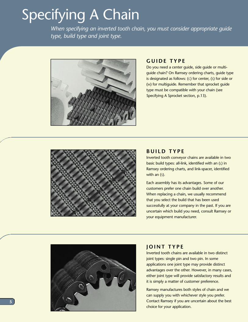
GU IDE T YP E Do you need a center guide, side guide or multi-guide chain? On Ramsey ordering charts, guide typeis designated as follows: (C) for center, (S) for side or(M) for multiguide. Remember that sprocket guidetype must be compatible with your chain (seeSpecifying A Sprocket section, p.13).
BU I LD TYP EInverted tooth conveyor chains are available in twobasic build types: all-link, identified with an (L) inRamsey ordering charts, and link-spacer, identifiedwith an (S).
Each assembly has its advantages. Some of ourcustomers prefer one chain build over another.When replacing a chain, we usually recommendthat you select the build that has been usedsuccessfully at your company in the past. If you areuncertain which build you need, consult Ramsey oryour equipment manufacturer.
J O INT TYP EInverted tooth chains are available in two distinctjoint types: single pin and two pin. In someapplications one joint type may provide distinctadvantages over the other. However, in many cases,either joint type will provide satisfactory results andit is simply a matter of customer preference.
Ramsey manufactures both styles of chain and wecan supply you with whichever style you prefer.Contact Ramsey if you are uncertain about the bestchoice for your application.
Specifying A Chain When specifying an inverted tooth chain, you must consider appropriate guidetype, build type and joint type.
5
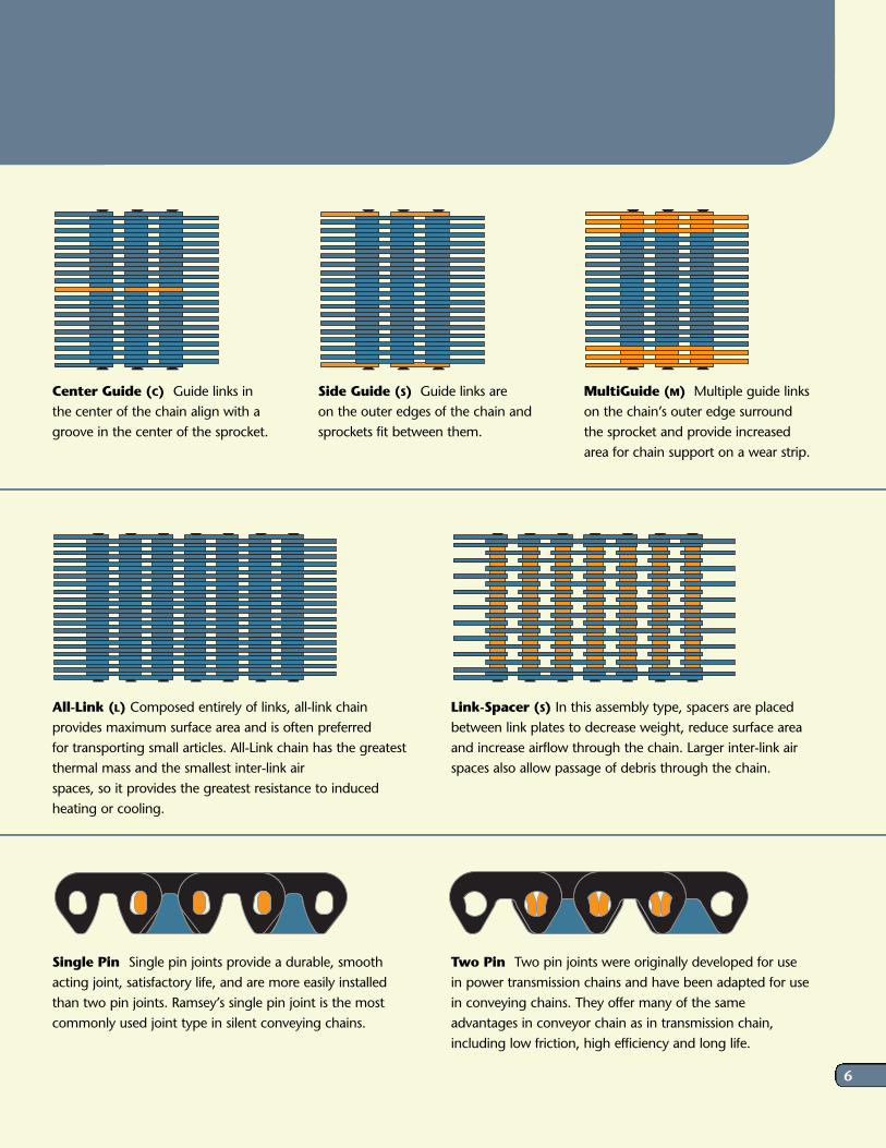
Center Guide (C) Guide links in the center of the chain align with agroove in the center of the sprocket.
Side Guide (S) Guide links are on the outer edges of the chain andsprockets fit between them.
MultiGuide (M) Multiple guide linkson the chain’s outer edge surroundthe sprocket and provide increasedarea for chain support on a wear strip.
All-Link (L) Composed entirely of links, all-link chainprovides maximum surface area and is often preferred for transporting small articles. All-Link chain has the greatestthermal mass and the smallest inter-link air spaces, so it provides the greatest resistance to inducedheating or cooling.
Link-Spacer (S) In this assembly type, spacers are placedbetween link plates to decrease weight, reduce surface areaand increase airflow through the chain. Larger inter-link airspaces also allow passage of debris through the chain.
Single Pin Single pin joints provide a durable, smoothacting joint, satisfactory life, and are more easily installedthan two pin joints. Ramsey’s single pin joint is the mostcommonly used joint type in silent conveying chains.
Two Pin Two pin joints were originally developed for usein power transmission chains and have been adapted for usein conveying chains. They offer many of the sameadvantages in conveyor chain as in transmission chain,including low friction, high efficiency and long life.
6
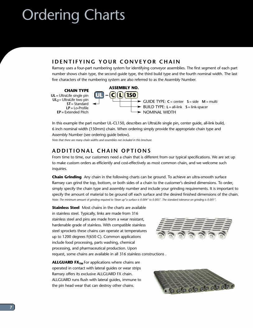
I D ENT I F Y ING YOUR CONVEYOR CHA INRamsey uses a four-part numbering system for identifying conveyor assemblies. The first segment of each partnumber shows chain type, the second guide type, the third build type and the fourth nominal width. The lastfive characters of the numbering system are also referred to as the Assembly Number.
In this example the part number UL-CL150, describes an UltraLife single pin, center guide, all-link build, 6 inch nominal width (150mm) chain. When ordering simply provide the appropriate chain type and Assembly Number (see ordering guide below). Note that there are many chain widths and assemblies not included in this brochure.
ADD I T IONAL CHA IN OPT IONS From time to time, our customers need a chain that is different from our typical specifications. We are set upto make custom orders as efficiently and cost-effectively as most common chain, and we welcome suchinquiries.
Chain Grinding Any chain in the following charts can be ground. To achieve an ultra-smooth surfaceRamsey can grind the top, bottom, or both sides of a chain to the customer’s desired dimensions. To order,simply specify the chain type and assembly number and include your grinding requirements. It is important tospecify the amount of material to be ground off each surface and the desired finished dimensions of the chain. Note: The minimum amount of grinding required to “clean up” a surface is 0.004" to 0.005". The standard tolerance on grinding is 0.001".
Stainless Steel Most chains in the charts are availablein stainless steel. Typically, links are made from 316stainless steel and pins are made from a wear resistant,hardenable grade of stainless. With compatible stainlesssteel sprockets these chains can operate at temperaturesup to 1200 degrees F(650 C). Common applicationsinclude food processing, parts washing, chemicalprocessing, and pharmaceutical production. Uponrequest, some chains are available in all 316 stainless constructions .
ALLGUARD FXTM For applications where chains areoperated in contact with lateral guides or wear stripsRamsey offers its exclusive ALLGUARD FX chain.ALLGUARD runs flush with lateral guides, immune tothe pin head wear that can destroy other chains.
UL= UltraLife single pinUL2= UltraLife two pin
ST= StandardLP= Lo-Profile
EP= Extended Pitch
Ordering Charts
CHAIN TYPEASSEMBLY NO.
GUIDE TYPE: C= center S= side M =multiBUILD TYPE: L= all-link S= link-spacerNOMINAL WIDTH
UL – C L 150
7
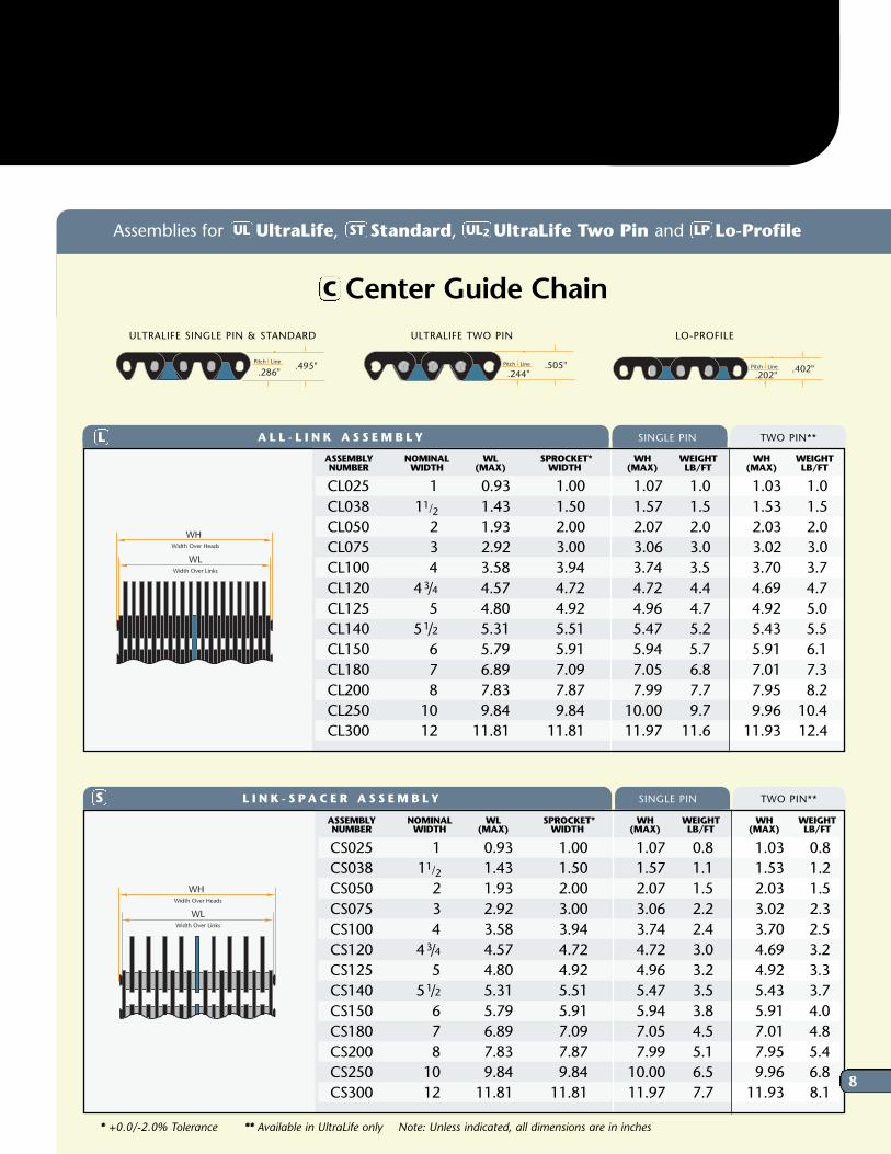
Center Guide ChainC
LO-PROFILEULTRALIFE TWO PIN
Pitch Line
.286".495"
Line
.
Pitch Line
.244".505"
Pitch Line
.202".402"
Line
.
Line
.
Line
.
Line
.
Assemblies for UltraLife, Standard, UltraLife Two Pin and Lo-ProfileUL UL2 LPST
A L L - L I N K A S S E M B L Y SINGLE PIN TWO PIN**L
* +0.0/-2.0% Tolerance ** Available in UltraLife only Note: Unless indicated, all dimensions are in inches
ASSEMBLY NOMINAL WL SPROCKET* WH WEIGHT WH WEIGHTNUMBER WIDTH (MAX) WIDTH (MAX) LB/FT (MAX) LB/FT
CL025 1 0.93 1.00 1.07 1.0 1.03 1.0CL038 11/2 1.43 1.50 1.57 1.5 1.53 1.5CL050 2 1.93 2.00 2.07 2.0 2.03 2.0CL075 3 2.92 3.00 3.06 3.0 3.02 3.0CL100 4 3.58 3.94 3.74 3.5 3.70 3.7 CL120 43/4 4.57 4.72 4.72 4.4 4.69 4.7 CL125 5 4.80 4.92 4.96 4.7 4.92 5.0 CL140 51/2 5.31 5.51 5.47 5.2 5.43 5.5 CL150 6 5.79 5.91 5.94 5.7 5.91 6.1 CL180 7 6.89 7.09 7.05 6.8 7.01 7.3 CL200 8 7.83 7.87 7.99 7.7 7.95 8.2 CL250 10 9.84 9.84 10.00 9.7 9.96 10.4 CL300 12 11.81 11.81 11.97 11.6 11.93 12.4
L I N K - S PA C E R A S S E M B L Y SINGLE PIN TWO PIN**S
ASSEMBLY NOMINAL WL SPROCKET* WH WEIGHT WH WEIGHT NUMBER WIDTH (MAX) WIDTH (MAX) LB/FT (MAX) LB/FT
CS025 1 0.93 1.00 1.07 0.8 1.03 0.8CS038 11/2 1.43 1.50 1.57 1.1 1.53 1.2CS050 2 1.93 2.00 2.07 1.5 2.03 1.5CS075 3 2.92 3.00 3.06 2.2 3.02 2.3CS100 4 3.58 3.94 3.74 2.4 3.70 2.5 CS120 43/4 4.57 4.72 4.72 3.0 4.69 3.2 CS125 5 4.80 4.92 4.96 3.2 4.92 3.3 CS140 51/2 5.31 5.51 5.47 3.5 5.43 3.7 CS150 6 5.79 5.91 5.94 3.8 5.91 4.0 CS180 7 6.89 7.09 7.05 4.5 7.01 4.8 CS200 8 7.83 7.87 7.99 5.1 7.95 5.4 CS250 10 9.84 9.84 10.00 6.5 9.96 6.8 CS300 12 11.81 11.81 11.97 7.7 11.93 8.1
Width Over Heads
WH
WLWidth Over Links
Width Over Heads
WH
WLWidth Over Links
ULTRALIFE SINGLE PIN & STANDARD
8
Ordering Charts
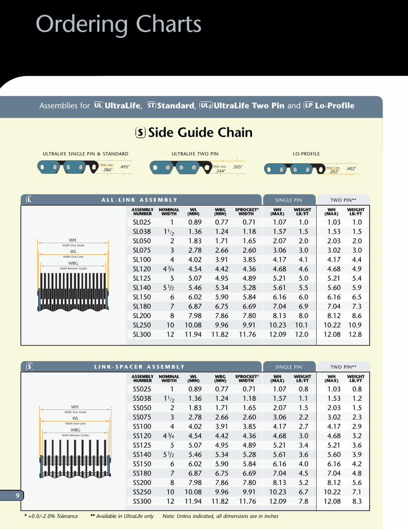
A L L - L I N K A S S E M B L Y SINGLE PIN TWO PIN**LASSEMBLY NOMINAL WL WBG SPROCKET* WH WEIGHT WH WEIGHTNUMBER WIDTH (MIN) (MIN) WIDTH (MAX) LB/FT (MAX) LB/FT
SL025 1 0.89 0.77 0.71 1.07 1.0 1.03 1.0SL038 11/2 1.36 1.24 1.18 1.57 1.5 1.53 1.5SL050 2 1.83 1.71 1.65 2.07 2.0 2.03 2.0SL075 3 2.78 2.66 2.60 3.06 3.0 3.02 3.0SL100 4 4.02 3.91 3.85 4.17 4.1 4.17 4.4 SL120 43/4 4.54 4.42 4.36 4.68 4.6 4.68 4.9 SL125 5 5.07 4.95 4.89 5.21 5.0 5.21 5.4 SL140 51/2 5.46 5.34 5.28 5.61 5.5 5.60 5.9 SL150 6 6.02 5.90 5.84 6.16 6.0 6.16 6.5 SL180 7 6.87 6.75 6.69 7.04 6.9 7.04 7.3 SL200 8 7.98 7.86 7.80 8.13 8.0 8.12 8.6 SL250 10 10.08 9.96 9.91 10.23 10.1 10.22 10.9 SL300 12 11.94 11.82 11.76 12.09 12.0 12.08 12.8
L I N K - S PA C E R A S S E M B L Y SINGLE PIN TWO PIN**S
Width Over Heads
WH
WLWidth Over Links
WBGWidth Between Guides
W
Width Over Heads
WH
WLWidth Over Links
WBGWidth Between Guides
* +0.0/-2.0% Tolerance ** Available in UltraLife only Note: Unless indicated, all dimensions are in inches
Pitch Line
.286".495"
Pitch Line
.244".505"
Line
2
Line
.
Pitch Line
.202".402"
LO-PROFILEULTRALIFE TWO PIN ULTRALIFE SINGLE PIN & STANDARD
Side Guide ChainS
Assemblies for UltraLife, Standard, UltraLife Two Pin and Lo-ProfileUL UL2 LPST
9
ASSEMBLY NOMINAL WL WBG SPROCKET* WH WEIGHT WH WEIGHTNUMBER WIDTH (MIN) (MIN) WIDTH (MAX) LB/FT (MAX) LB/FT
SS025 1 0.89 0.77 0.71 1.07 0.8 1.03 0.8SS038 11/2 1.36 1.24 1.18 1.57 1.1 1.53 1.2SS050 2 1.83 1.71 1.65 2.07 1.5 2.03 1.5SS075 3 2.78 2.66 2.60 3.06 2.2 3.02 2.3SS100 4 4.02 3.91 3.85 4.17 2.7 4.17 2.9 SS120 43/4 4.54 4.42 4.36 4.68 3.0 4.68 3.2 SS125 5 5.07 4.95 4.89 5.21 3.4 5.21 3.6 SS140 51/2 5.46 5.34 5.28 5.61 3.6 5.60 3.9 SS150 6 6.02 5.90 5.84 6.16 4.0 6.16 4.2 SS180 7 6.87 6.75 6.69 7.04 4.5 7.04 4.8 SS200 8 7.98 7.86 7.80 8.13 5.2 8.12 5.6 SS250 10 10.08 9.96 9.91 10.23 6.7 10.22 7.1 SS300 12 11.94 11.82 11.76 12.09 7.8 12.08 8.3
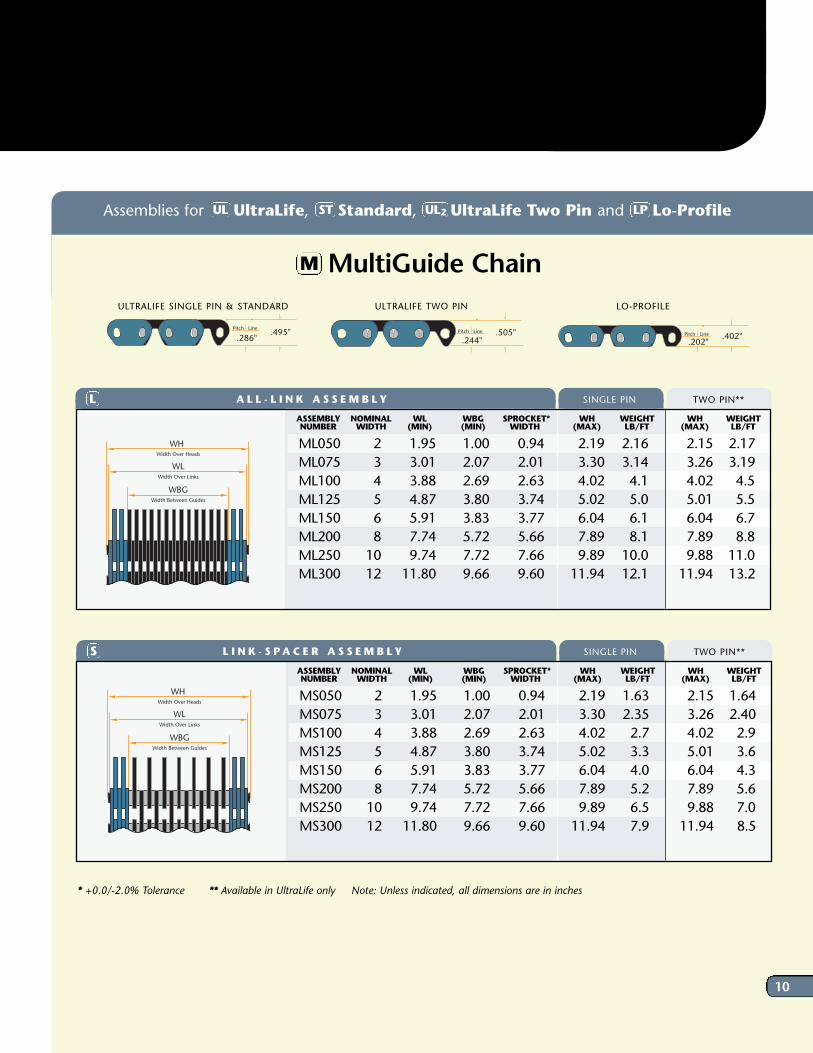
MultiGuide ChainM
* +0.0/-2.0% Tolerance ** Available in UltraLife only Note: Unless indicated, all dimensions are in inches
Pitch Line
.286".495"
Pitch Line
.244".505"
Line
2
Line
.
Line
.
Line
.
Pitch Line
.202".402"
Line
.
LO-PROFILEULTRALIFE TWO PIN ULTRALIFE SINGLE PIN & STANDARD
A L L - L I N K A S S E M B L Y SINGLE PIN TWO PIN**LASSEMBLY NOMINAL WL WBG SPROCKET* WH WEIGHT WH WEIGHTNUMBER WIDTH (MIN) (MIN) WIDTH (MAX) LB/FT (MAX) LB/FT
ML050 2 1.95 1.00 0.94 2.19 2.16 2.15 2.17ML075 3 3.01 2.07 2.01 3.30 3.14 3.26 3.19ML100 4 3.88 2.69 2.63 4.02 4.1 4.02 4.5 ML125 5 4.87 3.80 3.74 5.02 5.0 5.01 5.5 ML150 6 5.91 3.83 3.77 6.04 6.1 6.04 6.7 ML200 8 7.74 5.72 5.66 7.89 8.1 7.89 8.8 ML250 10 9.74 7.72 7.66 9.89 10.0 9.88 11.0 ML300 12 11.80 9.66 9.60 11.94 12.1 11.94 13.2
Width Over Heads
WH
WLWidth Over Links
WBGWidth Between Guides
W
L I N K - S PA C E R A S S E M B L Y SINGLE PIN TWO PIN**SASSEMBLY NOMINAL WL WBG SPROCKET* WH WEIGHT WH WEIGHTNUMBER WIDTH (MIN) (MIN) WIDTH (MAX) LB/FT (MAX) LB/FT
MS050 2 1.95 1.00 0.94 2.19 1.63 2.15 1.64MS075 3 3.01 2.07 2.01 3.30 2.35 3.26 2.40MS100 4 3.88 2.69 2.63 4.02 2.7 4.02 2.9 MS125 5 4.87 3.80 3.74 5.02 3.3 5.01 3.6 MS150 6 5.91 3.83 3.77 6.04 4.0 6.04 4.3 MS200 8 7.74 5.72 5.66 7.89 5.2 7.89 5.6 MS250 10 9.74 7.72 7.66 9.89 6.5 9.88 7.0 MS300 12 11.80 9.66 9.60 11.94 7.9 11.94 8.5
Width Over Heads
WH
WLWidth Over Links
WBGWidth Between Guides
Assemblies for UltraLife, Standard, UltraLife Two Pin and Lo-ProfileUL UL2 LPST
10
Ordering Charts
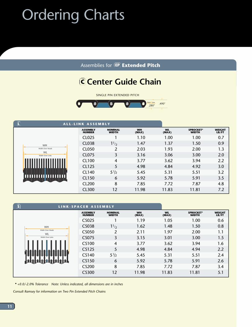
Assemblies for Extended Pitch
* +0.0/-2.0% Tolerance Note: Unless indicated, all dimensions are in inches
EP
Center Guide ChainC
Pitch Line
.280".490"
SINGLE PIN EXTENDED PITCH
A L L - L I N K A S S E M B L YLASSEMBLY NOMINAL WH WL SPROCKET* WEIGHTNUMBER WIDTH (MAX) (MAX) WIDTH LB/FT
CL025 1 1.10 1.00 1.00 0.7CL038 11/2 1.47 1.37 1.50 0.9CL050 2 2.03 1.93 2.00 1.3CL075 3 3.16 3.06 3.00 2.0CL100 4 3.77 3.62 3.94 2.2 CL125 5 4.98 4.84 4.92 3.0 CL140 51/2 5.45 5.31 5.51 3.2 CL150 6 5.92 5.78 5.91 3.5 CL200 8 7.85 7.72 7.87 4.8 CL300 12 11.98 11.83 11.81 7.2
Width Over Heads
WH
WLWidth Over Links
L I N K - S PA C E R A S S E M B L YSASSEMBLY NOMINAL WH WL SPROCKET* WEIGHTNUMBER WIDTH (MAX) (MAX) WIDTH LB/FT
CS025 1 1.19 1.05 1.00 0.6CS038 11/2 1.62 1.48 1.50 0.8CS050 2 2.11 1.97 2.00 1.1CS075 3 3.15 3.01 3.00 1.5CS100 4 3.77 3.62 3.94 1.6 CS125 5 4.98 4.84 4.94 2.2 CS140 51/2 5.45 5.31 5.51 2.4CS150 6 5.92 5.78 5.91 2.6 CS200 8 7.85 7.72 7.87 3.4 CS300 12 11.98 11.83 11.81 5.1
Width Over Heads
WH
WLWidth Over Links
11
Consult Ramsey for information on Two Pin Extended Pitch Chains
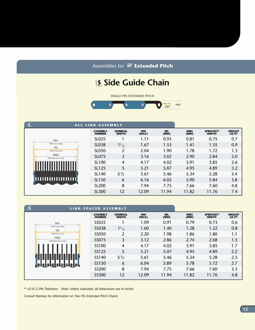
Side Guide ChainS
Assemblies for Extended Pitch
A L L - L I N K A S S E M B L YLASSEMBLY NOMINAL WH WL WBG SPROCKET* WEIGHTNUMBER WIDTH (MAX) (MIN) (MIN) WIDTH LB/FT
SL025 1 1.11 0.93 0.81 0.75 0.7SL038 11/2 1.67 1.53 1.41 1.35 0.9SL050 2 2.04 1.90 1.78 1.72 1.3SL075 3 3.16 3.02 2.90 2.84 2.0SL100 4 4.17 4.02 3.91 3.85 2.6SL125 5 5.21 5.07 4.95 4.89 3.2SL140 51/2 5.61 5.46 5.34 5.28 3.4 SL150 6 6.16 6.02 5.90 5.84 3.8 SL200 8 7.94 7.75 7.66 7.60 4.8 SL300 12 12.09 11.94 11.82 11.76 7.4
L I N K - S PA C E R A S S E M B L YSASSEMBLY NOMINAL WH WL WBG SPROCKET* WEIGHTNUMBER WIDTH (MAX) (MIN) (MIN) WIDTH LB/FT
SS025 1 1.09 0.91 0.79 0.73 0.6SS038 11/2 1.60 1.40 1.28 1.22 0.8SS050 2 2.20 1.98 1.86 1.80 1.1SS075 3 3.12 2.86 2.74 2.68 1.5SS100 4 4.17 4.02 3.91 3.85 1.7 SS125 5 5.21 5.07 4.95 4.89 2.2 SS140 51/2 5.61 5.46 5.34 5.28 2.3 SS150 6 6.04 5.89 5.78 5.72 2.7 SS200 8 7.94 7.75 7.66 7.60 3.3 SS300 12 12.09 11.94 11.82 11.76 4.8
Width Over Heads
WH
WLWidth Over Links
WBGWidth Between Guides
W
Width Over Heads
WH
WLWidth Over Links
WBGWidth Between Guides
Pitch Line
.280".490"
EP
SINGLE PIN EXTENDED PITCH
* +0.0/-2.0% Tolerance Note: Unless indicated, all dimensions are in inches
12
Consult Ramsey for information on Two Pin Extended Pitch Chains
All Ramsey conveyor chains operate on 1/2" pitchRamsey sprockets. Our sprockets are typicallymanufactured from C-1141 steel and are heattreated to provide hardened tooth surfaces.
Sprockets can be fully machined with finished boreand setscrews, or you can ask that they be suppliedwith an unfinished bore to allow further machining.
Specialized machining is available to accommodatea customer’s exact specifications. Materials, otherthan steel, are available upon request.
P ER FORMANCEGU IDE L INE SIn general, larger sprocket diameters will providefor smoother chain operation and less vibration, so it is best to avoid very small sprockets inapplications that require smooth transport. In most cases, sprockets for UltraLife, Standard, andLo-Profile chains should have a minimum of 21teeth. Sprockets for Extended Pitch Chains shouldhave at least 26 teeth.
Sprocket Tooth profiles are cut to establishedstandards to assure proper meshing of the sprocketand chain. Chain and sprocket dimensions must be
compatible for proper operation. Werecommend purchasing chain and
sprockets from the same source.
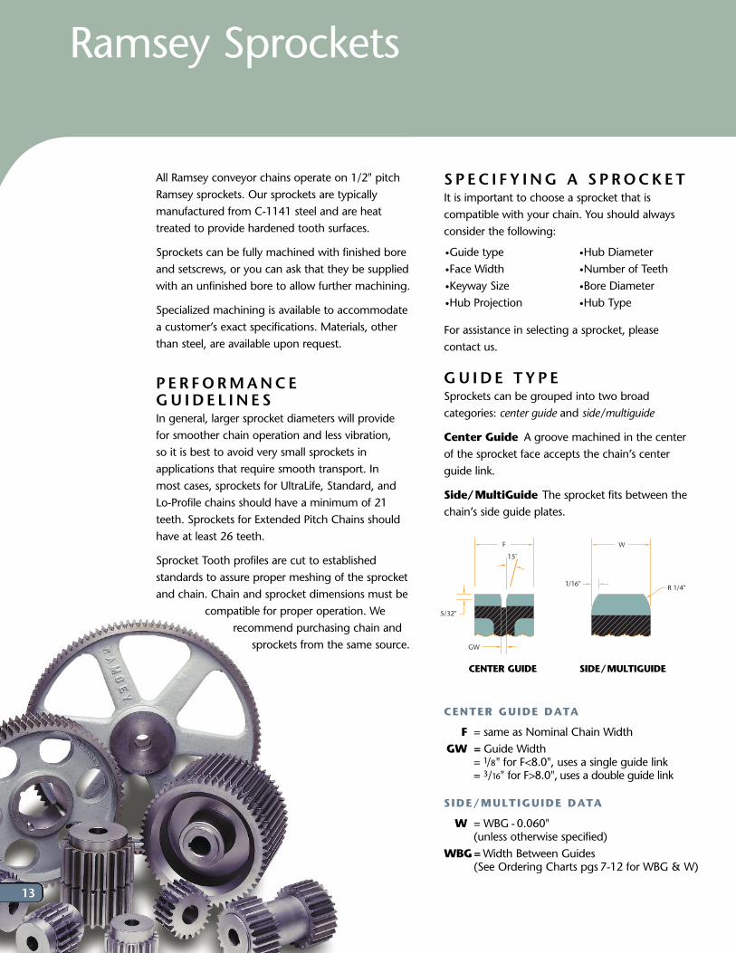
SP EC I F Y ING A S PROCKET It is important to choose a sprocket that iscompatible with your chain. You should alwaysconsider the following:
For assistance in selecting a sprocket, please contact us.
GU IDE T YP ESprockets can be grouped into two broadcategories: center guide and side/multiguide
Center Guide A groove machined in the center of the sprocket face accepts the chain’s centerguide link.
Side/MultiGuide The sprocket fits between thechain’s side guide plates.
CENTER GUIDE DATA
F = same as Nominal Chain WidthGW = Guide Width
= 1/8" for F<8.0", uses a single guide link= 3/16" for F>8.0", uses a double guide link
SIDE/MULTIGUIDE DATA
W = WBG -0.060"(unless otherwise specified)
WBG=Width Between Guides(See Ordering Charts pgs 7-12 for WBG & W)
• Guide type • Face Width• Keyway Size• Hub Projection
• Hub Diameter• Number of Teeth• Bore Diameter• Hub Type
Ramsey Sprockets
F
15˚
5/32"
GW
W
1/16"R 1/4"
S
CENTER GUIDE SIDE/MULTIGUIDE
13
14
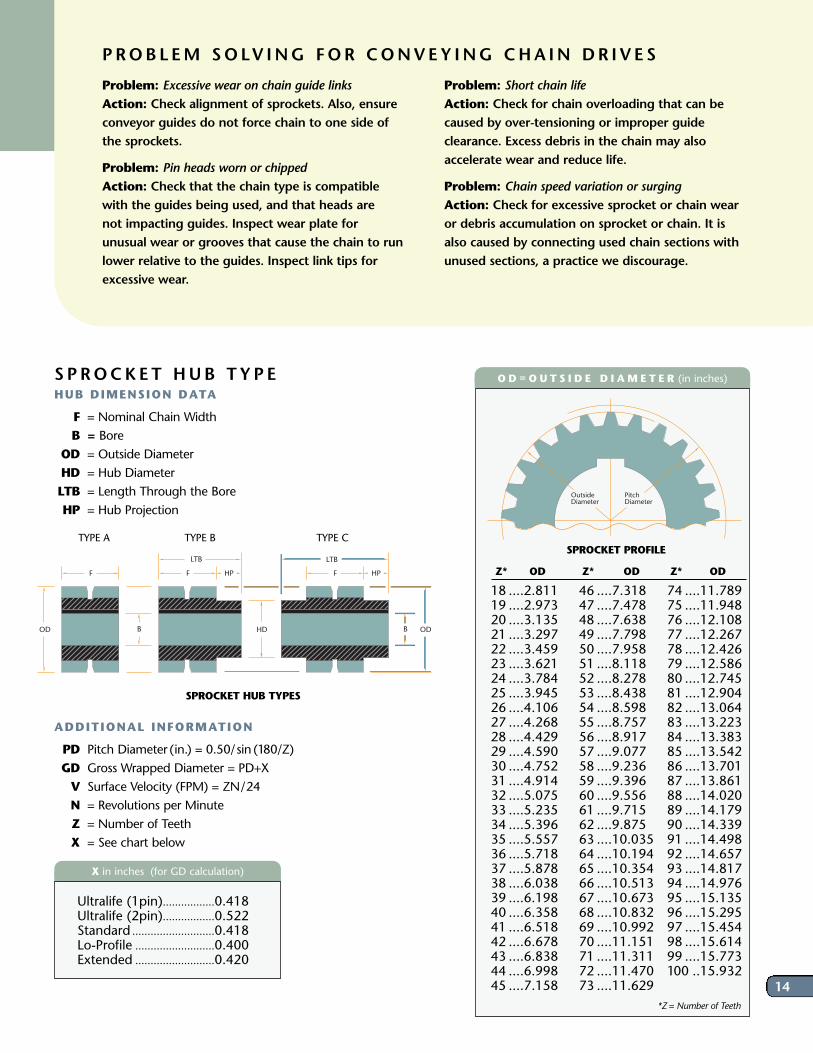
O D = O U T S I D E D I A M E T E R (in inches)
Z* OD
18 ....2.81119 ....2.97320 ....3.13521 ....3.29722 ....3.45923 ....3.62124 ....3.78425 ....3.94526 ....4.10627 ....4.26828 ....4.42929 ....4.59030 ....4.75231 ....4.91432 ....5.07533 ....5.23534 ....5.39635 ....5.55736 ....5.71837 ....5.87838 ....6.03839 ....6.19840 ....6.35841 ....6.51842 ....6.67843 ....6.83844 ....6.99845 ....7.158
Z* OD
46 ....7.31847 ....7.47848 ....7.63849 ....7.79850 ....7.95851 ....8.11852 ....8.27853 ....8.43854 ....8.59855 ....8.75756 ....8.91757 ....9.07758 ....9.23659 ....9.39660 ....9.55661 ....9.71562 ....9.87563 ....10.03564 ....10.19465 ....10.35466 ....10.51367 ....10.67368 ....10.83269 ....10.99270 ....11.15171 ....11.31172 ....11.47073 ....11.629
Z* OD
74 ....11.78975 ....11.94876 ....12.10877 ....12.26778 ....12.42679 ....12.58680 ....12.74581 ....12.90482 ....13.06483 ....13.22384 ....13.38385 ....13.54286 ....13.70187 ....13.86188 ....14.02089 ....14.17990 ....14.33991 ....14.49892 ....14.65793 ....14.81794 ....14.97695 ....15.13596 ....15.29597 ....15.45498 ....15.61499 ....15.773100 ..15.932
Pitch Diameter
Outside Diameter
SPROCKET PROFILE
*Z= Number of Teeth
PROBL EM SOLV ING FOR CONVEY ING CHA IN DR I V E S
Problem: Excessive wear on chain guide linksAction: Check alignment of sprockets. Also, ensureconveyor guides do not force chain to one side ofthe sprockets.
Problem: Pin heads worn or chippedAction: Check that the chain type is compatiblewith the guides being used, and that heads are not impacting guides. Inspect wear plate for unusual wear or grooves that cause the chain to runlower relative to the guides. Inspect link tips forexcessive wear.
Problem: Short chain lifeAction: Check for chain overloading that can becaused by over-tensioning or improper guideclearance. Excess debris in the chain may alsoaccelerate wear and reduce life.
Problem: Chain speed variation or surgingAction: Check for excessive sprocket or chain wearor debris accumulation on sprocket or chain. It isalso caused by connecting used chain sections withunused sections, a practice we discourage.
S P ROCKET HUB TYP EHUB DIMENSION DATA
F = Nominal Chain WidthB = Bore
OD = Outside DiameterHD = Hub DiameterLTB = Length Through the BoreHP = Hub Projection
ADDITIONAL INFORMATION
PD Pitch Diameter (in.) = 0.50/sin (180/Z)GD Gross Wrapped Diameter = PD+XV Surface Velocity (FPM) = ZN/24N = Revolutions per MinuteZ = Number of TeethX = See chart below
X in inches (for GD calculation)
Ultralife (1pin).................0.418Ultralife (2pin).................0.522Standard ...........................0.418Lo-Profile ..........................0.400Extended ..........................0.420
F F HP HPF
HD ODOD
LTB LTB
BB
TYPE A TYPE B TYPE C
SPROCKET HUB TYPES
Ramsey Products EuropeOldenkotsedijk 217481 VA HaaksbergenThe NetherlandsPh +31 (0)53 4306135Fax +31 (0)53 [email protected]
For over 40 years, Ramsey has been supplying chain to the international market. Our goal is to provide the widest range of top quality Inverted tooth
chains, unmatched service and competitive prices. Please contact Ramsey and let us show you how we can help enhance your growth and success.
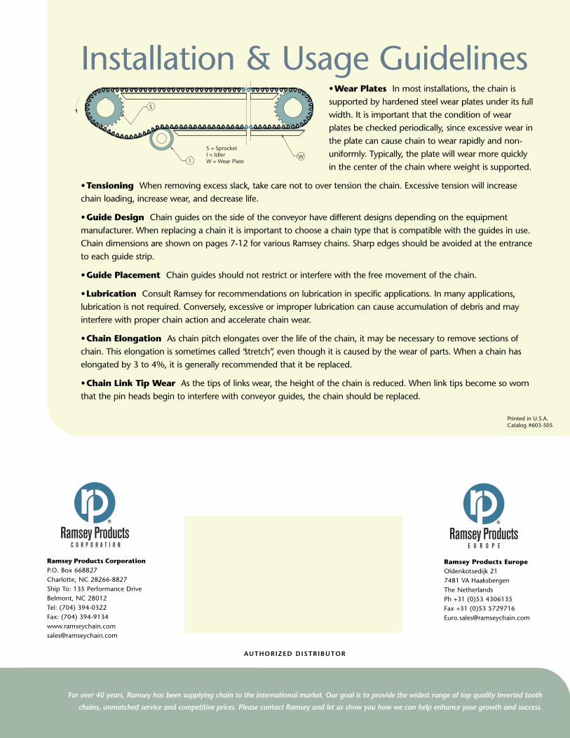
• Wear Plates In most installations, the chain issupported by hardened steel wear plates under its fullwidth. It is important that the condition of wearplates be checked periodically, since excessive wear inthe plate can cause chain to wear rapidly and non-uniformly. Typically, the plate will wear more quicklyin the center of the chain where weight is supported.
• Tensioning When removing excess slack, take care not to over tension the chain. Excessive tension will increasechain loading, increase wear, and decrease life.
• Guide Design Chain guides on the side of the conveyor have different designs depending on the equipmentmanufacturer. When replacing a chain it is important to choose a chain type that is compatible with the guides in use.Chain dimensions are shown on pages 7-12 for various Ramsey chains. Sharp edges should be avoided at the entranceto each guide strip.
• Guide Placement Chain guides should not restrict or interfere with the free movement of the chain.
• Lubrication Consult Ramsey for recommendations on lubrication in specific applications. In many applications,lubrication is not required. Conversely, excessive or improper lubrication can cause accumulation of debris and mayinterfere with proper chain action and accelerate chain wear.
• Chain Elongation As chain pitch elongates over the life of the chain, it may be necessary to remove sections ofchain. This elongation is sometimes called “stretch”, even though it is caused by the wear of parts. When a chain haselongated by 3 to 4%, it is generally recommended that it be replaced.
• Chain Link Tip Wear As the tips of links wear, the height of the chain is reduced. When link tips become so wornthat the pin heads begin to interfere with conveyor guides, the chain should be replaced.
S
IW
S = SprocketI = Idler W = Wear Plate
Installation & Usage Guidelines
Printed in U.S.A.Catalog #603-505
AUTHORIZED DISTRIBUTOR
Ramsey Products CorporationP.O. Box 668827Charlotte, NC 28266-8827Ship To: 135 Performance DriveBelmont, NC 28012Tel: (704) 394-0322Fax: (704) [email protected]