Embed Size (px)
DESCRIPTION
plumbing valve
Citation preview
www.valmatic.com
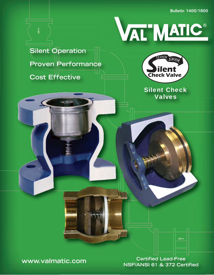
Silent Operation
Proven Performance
Cost Effective
Certified Lead-FreeNSF/ANSI 61 & 372 Certified
Silent CheckValves
ilentCheck Valve
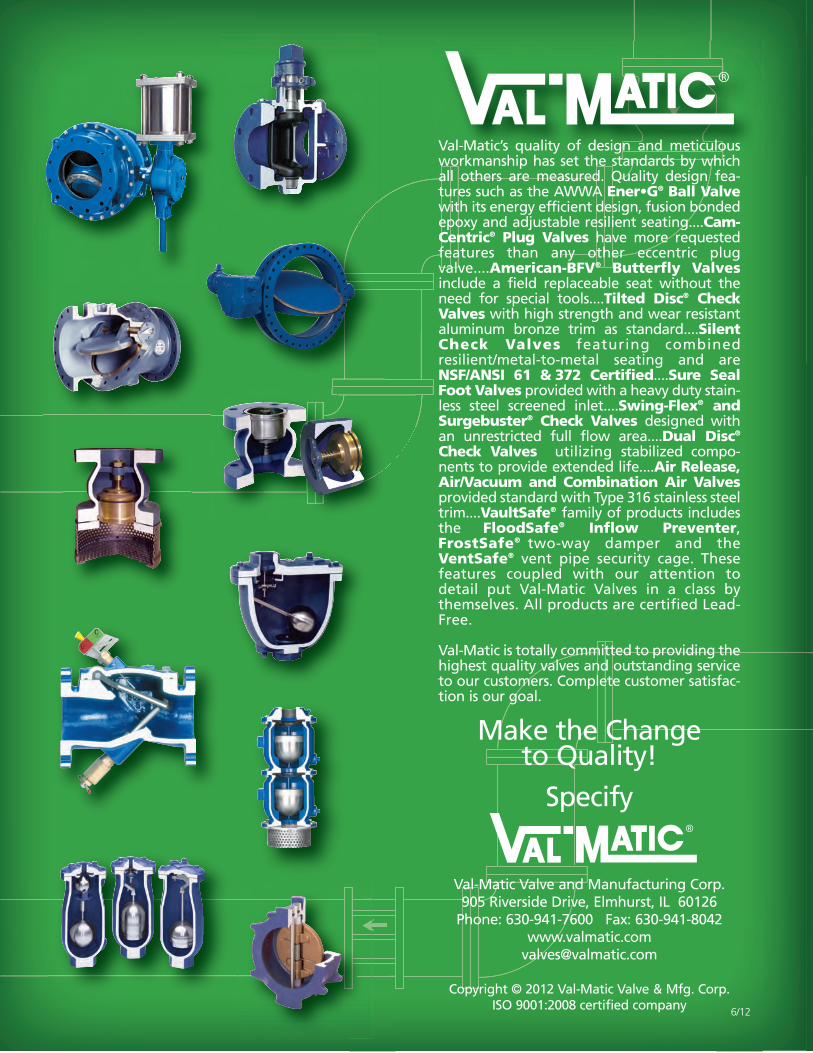
Val-Matic’s quality of design and meticulousworkmanship has set the standards by whichall others are measured. Quality design fea-tures such as the AWWA Ener•G® Ball Valvewith its energy efficient design, fusion bondedepoxy and adjustable resilient seating....Cam-Centric® Plug Valves have more requestedfeatures than any other eccentric plugvalve....American-BFV® Butterfly Valvesinclude a field replaceable seat without theneed for special tools....Tilted Disc® CheckValves with high strength and wear resistantaluminum bronze trim as standard....SilentCheck Valves featuring combinedresilient/metal-to-metal seating and areNSF/ANSI 61 & 372 Certified....Sure SealFoot Valves provided with a heavy duty stain-less steel screened inlet....Swing-Flex® andSurgebuster® Check Valves designed withan unrestricted full flow area....Dual Disc®
Check Valves utiliting stabilized compo-nents to provide extended life....Air Release,Air/Vacuum and Combination Air Valvesprovided standard with Type 316 stainless steeltrim....VaultSafe® family of products includesthe FloodSafe® Inflow Preventer,FrostSafe® two-way damper and theVentSafe® vent pipe security cage. Thesefeatures coupled with our attention todetail put Val-Matic Valves in a class bythemselves. All products are certified Lead-Free.
Val-Matic is totally committed to providing thehighest quality valves and outstanding serviceto our customers. Complete customer satisfac-tion is our goal.
Make the Change to Quality!
Specify
Val-Matic Valve and Manufacturing Corp.905 Riverside Drive, Elmhurst, IL 60126
Phone: 630-941-7600 Fax: 630-941-8042www.valmatic.com
Copyright © 2012 Val-Matic Valve & Mfg. Corp.ISO 9001:2008 certified company 6/12
Bulletin 1400/1800
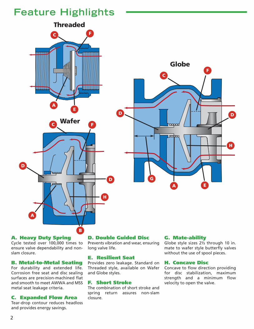
A. Heavy Duty SpringCycle tested over 100,000 times toensure valve dependability and non-slam closure.
B. Metal-to-Metal SeatingFor durability and extended life.Corrosion free seat and disc sealingsurfaces are precision-machined flatand smooth to meet AWWA and MSSmetal seat leakage criteria.
C. Expanded Flow AreaTear-drop contour reduces headlossand provides energy savings.
D. Double Guided DiscPrevents vibration and wear, ensuringlong valve life.
E. Resilient SeatProvides zero leakage. Standard onThreaded style, available on Waferand Globe styles.
F. Short StrokeThe combination of short stroke andspring return assures non-slamclosure.
G. Mate-abilityGlobe style sizes 2½ through 10 in.mate to wafer style butterfly valveswithout the use of spool pieces.
H. Concave DiscConcave to flow direction providingfor disc stabilization, maximumstrength and a minimum flowvelocity to open the valve.
Feature Highlights
A
B
C
2
A
A
C
C
D
D
EG
Threaded
Globe
Wafer
E
F
F
D
F
H
H
D

3
Features & BenefitsThe Val-Matic Silent Check Valve has been the preferredchoice by users for over 46 years. Its silent operation, lowcost and proven performance in clean water applicationshas made it a favorite by design engineers and systemoperators.
Silent OperationThe Silent Check Valve is preferred over other types ofvalves because of its silent operation which reducesshock and water hammer. The Silent Check Valve is thefastest closing check valve because of its short stroke andspring-assisted closure. When flow occurs, the disc islifted off the seat to allow forward flow. When thepump is stopped, the spring in the valve forces the discclosed before flow reverses, providing silent closure.Dynamic check valve tests show that surge pressure issignificantly reduced when a silent check valve is used.(See Figures 1 & 2)
Optional Resilient SeatThe Val-Matic Wafer and Globe Silent Check Valvesincorporate an optional disc/seat design that provideszero leakage and reduces the potential for o-ring sealdamage. The unique seating action begins with theinitial contact between the metal valve disc and the
resilient o-ring providing a low pressure seal (See Figure3). As pressure increases, the resilient seal is compressedwhich allows the disc to make contact with the metalportion of the valve seat (See Figure 4). This combinedwith excess area in the o-ring groove prevents overcompression of the synthetic seal. The design alsoprovides disc seal overlap of the resilient seal to preventindentation ridges that can cause leakage and sealdamage.
Installation VersatilityAll three styles of Silent Check Valves can be installed ineither horizontal or vertical lines with the flow up ordown.* The operation of the valve is not affected by itsinstallation position. Sizes 2 - 6 in. are dual rated to fitbetween both ANSI Class 125 and 250 flanges. Inapplications where space is limited, the compact waferstyle is the preferred choice. Globe Style Silent CheckValves in sizes 2½ - 10 in. are able to mate to wafer stylebutterfly valves without the use of spool pieces or anyother adaptors. (See Illustration on page 5.)
Product CertificationsVal-Matic Silent Check Valves are NSF/ANSI 372 certifiedLead-Free and are NSF/ANSI 61 certified for drinkingwater. Wafer style (2-10 in.) and Globe style (2½-12 in.)Silent Check Valves are Factory Mutual approved for usein fire protection systems. All Val-Matic Valves aremanufactured under a certified ISO 9001 qualitymanagement system.
180
160
140
120
100
80
60
40
20
00.2 0.4 0.6 0.8 1 1.2
Time (sec.)
Pres
sure
(p
si)
4” Silent Check Valve
Valve Closed
Pump StoppedSurge
Pressure(20 psi)
180
160
140
120
100
80
60
40
20
00.2 0.4 0.6 0.8 1 1.2
Time (sec.)
Pres
sure
(p
si)
4” Cushioned Swing Check Valve
Valve Closed
Pump Stopped
SurgePressure(130 psi)
RESILIENTSEAT
Figure 2 - Silent Check Valve Dynamic Test Results
DISC SEALOVERLAP
Figure 3 - Resilient Seating Detail at Low Pressure
Figure 4 - Resilient Seating Detail at High Pressure
Figure 1 - Cushioned Swing Check Valve Dynamic Test Results
*Note: Valves 14” and larger require a heavy duty spring for flow down applications.
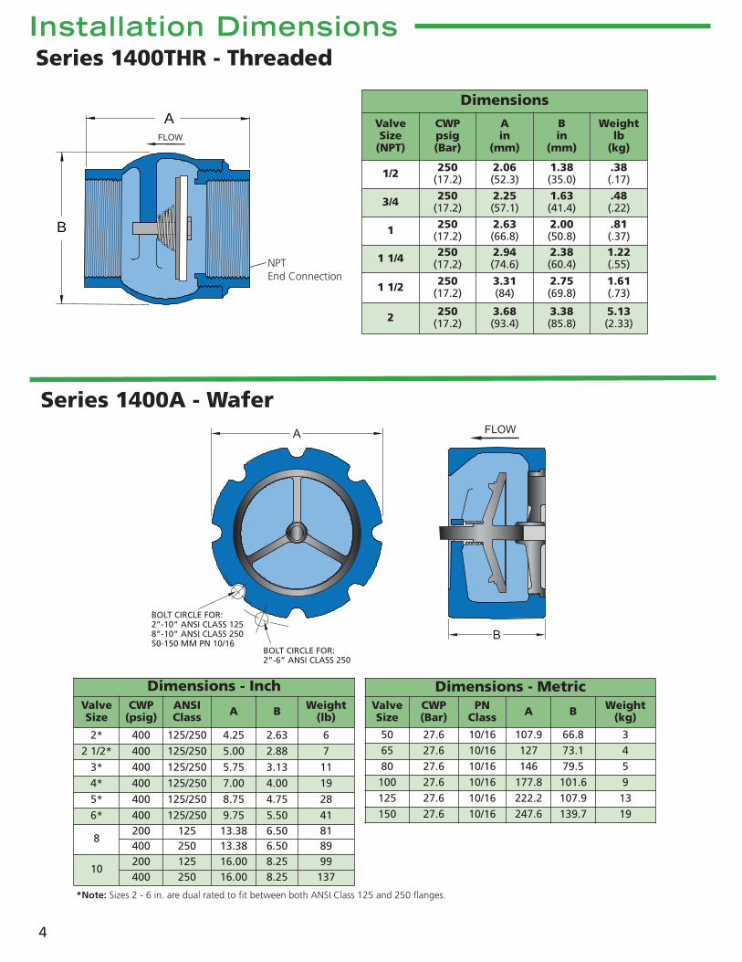
Installation Dimensions
A
B
NPTEnd Connection
BOLT CIRCLE FOR:2”-10” ANSI CLASS 1258”-10” ANSI CLASS 25050-150 MM PN 10/16
BOLT CIRCLE FOR:2”-6” ANSI CLASS 250
4
Series 1400A - Wafer
Series 1400THR - Threaded
Dimensions - InchValveSize
CWP(psig)
ANSIClass A B Weight
(lb)
2* 400 125/250 4.25 2.63 62 1/2* 400 125/250 5.00 2.88 7
3* 400 125/250 5.75 3.13 114* 400 125/250 7.00 4.00 195* 400 125/250 8.75 4.75 286* 400 125/250 9.75 5.50 41
8200 125 13.38 6.50 81400 250 13.38 6.50 89
10200 125 16.00 8.25 99400 250 16.00 8.25 137
Dimensions
ValveSize
(NPT)
CWPpsig(Bar)
Ain
(mm)
Bin
(mm)
Weightlb
(kg)
1/2 250(17.2)
2.06(52.3)
1.38(35.0)
.38(.17)
3/4 250(17.2)
2.25(57.1)
1.63(41.4)
.48(.22)
1 250(17.2)
2.63(66.8)
2.00(50.8)
.81(.37)
1 1/4 250(17.2)
2.94(74.6)
2.38(60.4)
1.22(.55)
1 1/2 250(17.2)
3.31(84)
2.75(69.8)
1.61(.73)
2 250(17.2)
3.68(93.4)
3.38(85.8)
5.13(2.33)
Dimensions - MetricValveSize
CWP(Bar)
PNClass A B Weight
(kg)
50 27.6 10/16 107.9 66.8 365 27.6 10/16 127 73.1 480 27.6 10/16 146 79.5 5100 27.6 10/16 177.8 101.6 9125 27.6 10/16 222.2 107.9 13150 27.6 10/16 247.6 139.7 19
*Note: Sizes 2 - 6 in. are dual rated to fit between both ANSI Class 125 and 250 flanges.

Installation Dimensions
5
A
C
B
D
Flanges conform toANSI B16.1 Class 125 or 250or ISO 7005 PN10 or PN16
Note: Valves 2½ (65 mm) - 10 in. (250mm)mate to wafer style butterfly valveswithout the use of spool pieces.
Butterfly Disc
Series 1800 - Globe
Dimensions - InchValveSize
CWP(psig)
ANSIClass A B C D Weight
(lb)
2 1/2200 125 7.00 5.50 5.50 0.69 19400 250 7.50 5.50 5.88 1.00 30
3200 125 7.50 6.00 6.00 0.94 28400 250 8.25 6.00 6.63 1.13 36
4200 125 9.00 7.25 7.50 0.94 43400 250 10.00 7.25 7.88 1.25 59
5200 125 10.00 8.50 8.50 0.94 55400 250 11.00 8.50 9.75 1.38 78
6200 125 11.00 9.75 9.50 1.00 78400 250 12.50 9.75 10.63 1.44 103
8200 125 13.50 12.50 11.75 1.13 102400 250 15.00 12.50 13.00 1.63 179
10200 125 16.00 15.50 14.25 1.19 208
400 250 17.50 15.50 15.25 1.88 253
12200 125 19.00 14.25 17.00 1.25 294400 250 20.50 14.25 17.75 2.00 401
14150 125 21.00 15.75 18.75 1.38 380300 250 23.00 15.75 20.25 2.13 511
16150 125 23.50 17.63 21.25 1.44 501300 250 25.50 17.63 22.50 2.25 697
18150 125 25.00 18.75 22.75 1.56 724
300 250 28.00 18.75 24.75 2.38 959
20150 125 27.50 20.63 25.00 1.69 890300 250 30.50 20.63 27.00 2.50 1,180
24150 125 32.00 24.00 29.50 1.88 1,220300 250 36.00 24.00 32.00 2.75 1,680
30150 125 38.75 29.25 36.00 2.13 2,100300 250 43.00 29.25 39.25 3.00 2,700
36150 125 46.00 45.00 42.75 2.38 4,400300 250 50.00 46.00 46.00 3.38 5,100
42150 125 53.00 50.00 49.50 2.63 7,200300 250 57.00 50.00 52.75 3.69 7,900
Dimensions - MetricValveSize
CWP(Bar)
PNClass A B C D Weight
(kg)
65 16 10/16 178 140 145 18 9
80 16 10/16 192 152 160 24 13
100 16 10/16 220 184 180 24 20
125 16 10/16 250 216 210 24 25
150 16 10/16 285 248 240 25 35
20016 10 340 318 295 29 4616 16 340 318 295 29 81
25016 10 395 362 350 30 94
16 16 405 362 355 30 114
30016 10 445 394 400 32 13316 16 460 394 410 32 181
35010 10 505 400 460 35 17216 16 520 400 470 35 231
40010 10 565 448 515 37 22716 16 580 448 525 37 316
45010 10 615 476 565 40 328
16 16 640 476 585 40 434
50010 10 670 524 620 43 40316 16 715 524 650 43 535
60010 10 780 610 725 48 55316 16 840 610 770 48 762
6
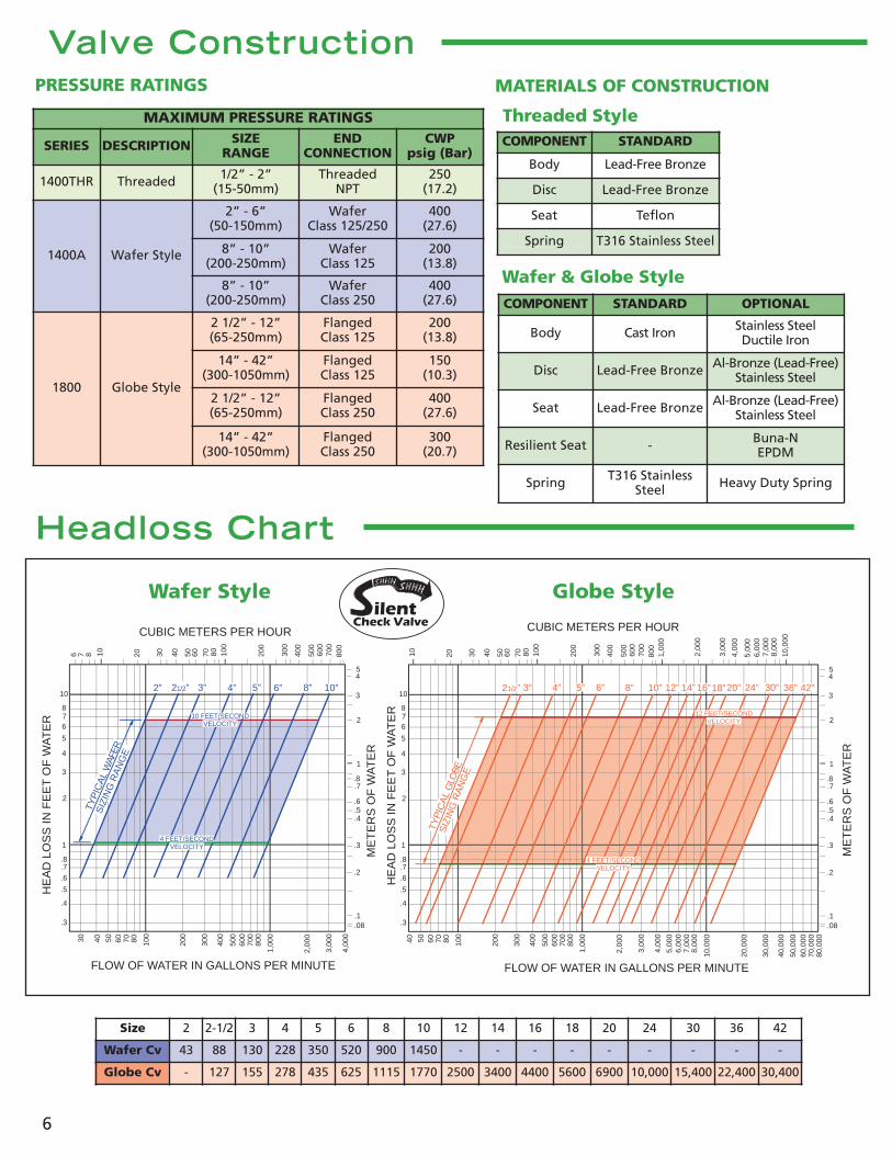
Valve ConstructionPRESSURE RATINGS MATERIALS OF CONSTRUCTION
MAXIMUM PRESSURE RATINGS
SERIES DESCRIPTION SIZERANGE
ENDCONNECTION
CWPpsig (Bar)
1400THR Threaded 1/2” - 2”(15-50mm)
ThreadedNPT
250(17.2)
1400A Wafer Style
2” - 6”(50-150mm)
WaferClass 125/250
400(27.6)
8” - 10”(200-250mm)
WaferClass 125
200(13.8)
8” - 10”(200-250mm)
WaferClass 250
400(27.6)
1800 Globe Style
2 1/2” - 12”(65-250mm)
FlangedClass 125
200(13.8)
14” - 42”(300-1050mm)
FlangedClass 125
150(10.3)
2 1/2” - 12”(65-250mm)
FlangedClass 250
400(27.6)
14” - 42”(300-1050mm)
FlangedClass 250
300(20.7)
COMPONENT STANDARD OPTIONAL
Body Cast Iron Stainless SteelDuctile Iron
Disc Lead-Free Bronze Al-Bronze (Lead-Free)Stainless Steel
Seat Lead-Free Bronze Al-Bronze (Lead-Free)Stainless Steel
Resilient Seat - Buna-NEPDM
Spring T316 StainlessSteel Heavy Duty Spring
Headloss Chart
COMPONENT STANDARD
Body Lead-Free Bronze
Disc Lead-Free Bronze
Seat Teflon
Spring T316 Stainless Steel
Threaded Style
Wafer & Globe Style
Size 2 2-1/2 3 4 5 6 8 10 12 14 16 18 20 24 30 36 42
Wafer Cv 43 88 130 228 350 520 900 1450 - - - - - - - - -
Globe Cv - 127 155 278 435 625 1115 1770 2500 3400 4400 5600 6900 10,000 15,400 22,400 30,400
10
876
5
4
3
2
1
.8
.7
.6
.5
.4
.3
10 20 30 40 50 60 70 80 100
200
300
400
500
600
700
800
1,00
0
2,00
0
3,00
0
4,00
0
5,00
06,
000
7,00
08,
000
10,0
00
40 50 60 70 80 100
200
300
400
500
600
700
800
1,00
0
2,00
0
3,00
0
4,00
0
5,00
06,
000
7,00
08,
000
10,0
00
20,0
00
30,0
00
40,0
00
50,0
0060
,000
70,0
0080
,000
.08
.1
.2
.3
.4
.5
.6
.7.8
1
2
3
45
HE
AD
LO
SS
IN F
EE
T O
F W
AT
ER
FLOW OF WATER IN GALLONS PER MINUTE
CUBIC METERS PER HOUR
ME
TE
RS
OF
WA
TE
RDNOCES/TEEF 4
YTICOLEV
12 FEET/SECONDVELOCITY
18” 42”36”30”24”20”16”14”12”10”4”3” 5” 6” 8”21/2”
TYP
ICA
L G
LOBE
SIZ
ING
RA
NG
E
10
876
5
4
3
2
1
.8
.7
.6
.5
.4
.3
6 7 8 10 20 30 40 50 60 70 80 100
200
300
400
500
600
700
800
30 40 50 60 70 80 100
200
300
400
500
600
700
800
1,00
0
2,00
0
3,00
0
4,00
0
.08
.1
.2
.3
.4
.5
.6
.7.8
1
2
3
45
HE
AD
LO
SS
IN F
EE
T O
F W
AT
ER
FLOW OF WATER IN GALLONS PER MINUTE
CUBIC METERS PER HOUR
ME
TE
RS
OF
WA
TE
R
TYP
ICA
L W
AFER
SIZ
ING
RA
NG
E
DNOCES/TEEF 4YTICOLEV
10 FEET/SECONDVELOCITY
2” 6”1/2”2 3” 4” 5” 8” 10”
Wafer Style Globe Styleilent
Check Valve

7
SpecificationsSCOPE1.1 This specification covers the design, manufacture,
and testing of 1/2 in. (15 mm) through 2 in. (50 mm)Bronze Threaded Silent Check Valves, 2 in. (50 mm)through 10 in. (250 mm) Wafer Silent Check Valvesand 2 1/2 in. (65 mm) through 42 in. (1050 mm)Globe Silent Check Valves suitable for pressures upto 500 psig (3450 kPa) water service.
1.2 The Check Valve shall be of the silent operating typethat begins to close as the forward flow diminishesand fully closes at zero velocity preventing flowreversal and resultant water hammer. The dynamiccharacteristics of the valve shall be published andverified by independent laboratory test data.
STANDARDS AND APPROVALS2.1 The valves for use in fire protection systems shall be
Factory Mutual approved in Wafer Style sizes 2 in.-6 in Class 125/250, 8 in.- 10 in. Class 125 and GlobeStyle 2 1/2 in.- 10 in. Class 125/250, 12 in. Class 125.
2.2 Stainless steel valves shall meet the requirements ofASME B16.34 and MSS SP-126.
2.3 The valves used in potable water service shall becertified to NSF/ANSI 61, Drinking Water SystemComponents – Health Effects, and certified to beLead-Free in accordance with NSF/ANSI 372.
2.4 Manufacturer shall have a quality managementsystem that is certified to ISO 9001 by an accredited,certifying body.
CONNECTIONS3.1 Threaded Style valves shall be provided in sizes ½ in.
(15mm) through 2 in. (50mm) and have a two-piecebody with female threaded NPT ends.
3.2 Globe style valves shall be provided in sizes 2 1/2 in.(65 mm) through 42 in. (1050 mm) and have flatfaced flanges in accordance with ASME B16.1 forClass 125 or Class 250 iron flanges or in sizes 65 mmto 600 mm in accordance with ISO 7005 PN10 orPN16. Sizes 10 in. (250 mm) and smaller flangedvalves shall be capable of mating directly to a waferbutterfly valve without disc interference.
3.3 Wafer style valves shall be provided in sizes 2 in. (50mm) through 10 in. (250 mm) for installationbetween ASME B16.1 Class 125 or Class 250 ironflanges or sizes 50 mm to 100 mm in accordance withISO 7005 PN10 or PN16. Stainless steel wafer stylevalves shall include raised faces for installationbetween ASME B16.5 Class 150 flanges.
DESIGN4.1 The valve design shall incorporate a center guided,
spring loaded disc and have a short linear strokethat generates a flow area equal to the nominalvalve size.
4.2 The operation of the valve shall not be affected bythe position of installation. The valve shall becapable of operating in the horizontal or verticalpositions with the flow up or down. Heavy dutysprings for vertical flow down installations shall beprovided when specified on 14 in. and larger valves.
4.3 All component parts shall be field replaceablewithout the need of special tools. Wafer and Globestyles shall be provided with a replaceable guidebushing held in position by the spring. The springshall be designed to withstand 100,000 cycleswithout failure and provide a cracking pressure of0.5 psi.
4.4 The wafer and globe disc shall be concave to theflow direction providing for disc stabilization,maximum strength, and a minimum flow velocity toopen the valve.
4.5 The valve disc and seat shall have a seating surfacefinish of 16 micro-inch or better to ensure positiveseating at all pressures. The leakage rate shall notexceed the allowable rate for metal seated valvesallowed by AWWA C508 and MSS SP-125 or 1 fl oz(30 ml) per hour per inch of nominal size.
4.6 Wafer-style valve seats shall be fully retained withfull size threads, and sealed with an o-ring. Globestyle valve seats shall be contained with a machinedcounterbore and restrained by the mating flangeand gasket.
MATERIALS5.1 The threaded valve body and disc shall be ASTM
B584 copper alloy C87600 lead-free bronze. The seatshall be TFE. The spring shall be Type 316 stainlesssteel.
5.2 Globe and wafer valve bodies shall be constructed ofASTM A126 Class B cast iron for Class 125 and Class250 valves and ASTM A351 Grade CF8M for Class 150stainless steel valves. Optional body materialincludes ASTM A536 Grade 65-45-12 ductile iron.
5.3 Globe and wafer seat and disc shall be ASTM B584Alloy C83600 cast bronze or ASTM B148 Alloy C95200aluminum bronze. Optional trim material includesASTM B584 copper alloy C87600 lead-free bronze orASTM A351 Grade CF8M stainless steel.
5.4 Globe and wafer compression spring shall be ASTMA313 Type 316 stainless steel with ground ends.
OPTIONS6.1 A resilient seal shall be provided on the seat when
specified to provide zero leakage at both high andlow pressures without overloading or damaging theseal. The seal design shall provide both a metal-to-metal and a metal-to-resilient seal.
6.2 Valve interiors and exteriors shall be coated with anNSF/ANSI 61 certified fusion bonded epoxy inaccordance with AWWA C550 when specified.
MANUFACTURE7.1 The valves shall be hydrostatically tested at 1.5 times
their rated cold working pressure and seat tested atthe valve CWP. When requested, the manufacturershall provide test certificates, dimensional drawings,parts list drawings, and operation and maintenancemanuals.
7.2 The exterior of the valve shall be coated with auniversal alkyd primer.
7.3 Silent Check Valves shall be Series #1400THR.1(Threaded Style), Series #1400A (Wafer Style) or 1800(Globe Style) as manufactured by Val-Matic® Valve& Mfg. Corporation, Elmhurst, IL. USA or approvedequal.
www.valmatic.com
Silent Operation
Proven Performance
Cost Effective
Certified Lead-FreeNSF/ANSI 61 & 372 Certified
Silent CheckValves
ilentCheck Valve
Val-Matic’s quality of design and meticulousworkmanship has set the standards by whichall others are measured. Quality design fea-tures such as the AWWA Ener•G® Ball Valvewith its energy efficient design, fusion bondedepoxy and adjustable resilient seating....Cam-Centric® Plug Valves have more requestedfeatures than any other eccentric plugvalve....American-BFV® Butterfly Valvesinclude a field replaceable seat without theneed for special tools....Tilted Disc® CheckValves with high strength and wear resistantaluminum bronze trim as standard....SilentCheck Valves featuring combinedresilient/metal-to-metal seating and areNSF/ANSI 61 & 372 Certified....Sure SealFoot Valves provided with a heavy duty stain-less steel screened inlet....Swing-Flex® andSurgebuster® Check Valves designed withan unrestricted full flow area....Dual Disc®
Check Valves utilizing stabilized compo-nents to provide extended life....Air Release,Air/Vacuum and Combination Air Valvesprovided standard with Type 316 stainless steeltrim....VaultSafe® family of products includesthe FloodSafe® Inflow Preventer,FrostSafe® two-way damper and theVentSafe® vent pipe security cage. Thesefeatures coupled with our attention todetail put Val-Matic Valves in a class bythemselves. All products are certified Lead-Free.
Val-Matic is totally committed to providing thehighest quality valves and outstanding serviceto our customers. Complete customer satisfac-tion is our goal.
Make the Change to Quality!
Specify
Val-Matic Valve and Manufacturing Corp.905 Riverside Drive, Elmhurst, IL 60126
Phone: 630-941-7600 Fax: 630-941-8042www.valmatic.com
Copyright © 2012 Val-Matic Valve & Mfg. Corp.ISO 9001:2008 certified company 6/12
Bulletin 1400/1800