Embed Size (px)
Citation preview

N. Lior
K. Koal Department of Mechanical Engineering
and Applied Mechanics, University of Pennsylvania,
Philadelphia, Pa 19104
Silar-Powered/Fuel-Assisted Rankine-Cycle Power and Cooiing-
tem: Simulation Method and sasonaS Performance
The subject of this analysis is a solar cooling system based on a novel hybrid steam Rankine cycle. Steam is generated by the use of solar energy collected at about 100" C, and it is then superheated to about 600° C in a fossil-fuel-fired superheater. The addition of about 20-26 percent of fuel doubles the power cycle's efficiency as compared to organic Rankine cycles operating at similar collector temperatures. A comprehensive computer program was developed to analyze the operation and performance of the entire power/cooling system. Transient simulation was performed on an hourly basis over a cooling season in two representative climatic regions ( Washington, D.C. and Phoenix, Ariz.). One of the conclusions is that the seasonal system COP is 0.82 for the design configuration and that the use of water-cooled condensers and flat-plate collectors of higher efficiency increases this value to 1.35.
1 Introduction
As compared to most of the other Rankine-cycle concepts for generating power from low-temperature (<150°C) solar energy sources, which are characterized by using organic working fluids and powered by solar energy alone (see reviews in [1-5]), the concept described here uses steam in a hybrid solar/fossil-powered cycle. The principle of this concept is the elevation of the top cycle temperature by superheating the steam to improve cycle efficiency, and use of energy from two different temperature levels to provide better thermodynamic matching with the energy sinks in the cycle. Since the boiling of the water is accomplished at relatively low temperatures (around 100°C), about 80 percent of the heat can be supplied by solar collectors at this relatively low temperature, and the remaining 20 percent needed for superheating (up to about 600°C) can be supplied by fossil fuel (see analyses in [1, 5-7]). These analyses have shown that at the same time the efficiency of the Rankine cycle is essentially doubled when compared to that of organic fluid Rankine cycles that operate at similar solar collector temperatures, from about 9 to about 18 percent. Since the solar collectors account for a major fraction of the total system's cost (typically more than a half), of most significance is the fact that this hybrid cycle, named SSPRE (Solar Steam Powered Rankine Engine, pronouned 'espree'), was found in the aformentioned studies to require only about half the collector area as compared to cycles using organic fluids, and to operate at a lower collector temperature at that. At present collector and fuel prices, the SSPRE concept has a major economic advantage. Rising fuel costs and possibly declining collectors costs may change this situation, but at
such time solar concentrators are expected to become sufficiently economical so that they may replace fossil-fuel superheating, for an all-solar operation. Here again, the principle of matching energy sources and sinks of similar temperature allows the use of low-temperature, low-cost collectors to supply the major portion of the energy (latent heat), and the use of a small quantity of high-temperature higher-cost concentrators to supply the superheat.
The SSPRE system with application to solar cooling has been under analytical and hardware development at the University of Pennsylvania for a number of years, (testing is due to start soon) and its flow diagram is shown in Fig. 1. Heat recovery within the cycle is obtained by a regenerator
Rankine Cycle
Contributed by the Solar Energy Division for publication in the JOURNAL OF SOLAR ENERGY ENGINEERING, Manuscript received by the Solar Energy Division June 25, 1982.
Chilled Water
Fig. 1 The solar-powered/fuel-superheated steam Rankine cycle (SSPRE) driving a vapor-compression chiller
142/Vol. 106, May 1984 Transactions of the ASME Copyright © 1984 by ASME
Downloaded 05 Mar 2012 to 158.130.78.155. Redistribution subject to ASME license or copyright; see http://www.asme.org/terms/Terms_Use.cfm
g-
N. Lim
K. Koai Department of Mechanical Engineering
and Applied Mechanics, University of Pennsylvania,
Philadelphia, Pa 19104
The subject of this analysis is a solar cooling system based on a novel hybrid steam Rankine cycle. Steam is generated by the use of solar energy collected at about 100° C, and it is then superheated to about 600° C in a fossil-fuel-fired superheater. The addition of about 20-26 percent of fuel doubles the power cycle's efficiency as compared to organic Rankine cycles operating at similar collector temperatures. A comprehensive computer program was developed to analyze the operation and performance of the entire power/cooling system, Transient simulation was performed on an hourly basis over a cooling season in two representative climatic regions ( Washington, D.C. and Phoenix, Ariz.). One of the conclusions is that the seasonal system COP is 0.82 for the design configuration and that the use of watercooled condensers and flat-plate collectors of higher efficiency increases this value to 1.35.
1 Introduction As compared to most of the other Rankine-cycle concepts
for generating power from low-temperature « 150°C) solar energy sources, which are characterized by using organic working fluids and powered by solar energy alone (see reviews in [1-5]), the concept described here uses steam in a hybrid solar/fossil-powered cycle. The principle of this concept is the elevation of the top cycle temperature by superheating the steam to improve cycle efficiency, and use of energy from two different temperature levels to provide better thermodynamic matching with the energy sinks in the cycle. Since the boiling of the water is accomplished at relatively low temperatures (around lOO°C), about 80 percent of the heat can be supplied by solar collectors at this relatively low temperature, and the remaining 20 percent needed for superheating (up to about 600°C) can be supplied by fossil fuel (see analyses in [1,5-7]). These analyses have shown that at the same time the efficiency of the Rankine cycle is essentially doubled when compared to that of organic fluid Rankine cycles that operate at similar solar collector temperatures, from about 9 to about 18 percent. Since the solar collectors account for a major fraction of the total system's cost (typically more than a half), of most significance is the fact that this hybrid cycle, named SSPRE (Solar Steam Powered Rankine Engine, pronouned 'espree'), was found in the aformentioned studies to require only about half the collector area as compared to cycles using organic fluids, and to operate at a lower collector temperature at that. At present collector and fuel prices, the SSPRE concept has a major economic advantage. Rising fuel costs and possibly declining collectors costs may change this situation, but at
Contributed by the Solar Energy Division for publication in the JOURNAL OF SOLAR ENERGY ENGINEERING. Manuscript received by the Solar Energy Division June 25, 1982.
142/Vol.106, May 1984
such time solar concentrators are expected to become sufficiently economical so that they may replace fossil-fuel superheating, for an all-solar operation. Here again, the principle of matching energy sources and sinks of similar temperature allows the use of low-temperature, low-cost collectors to supply the major portion of the energy (latent heat), and the use of a small quantity of high-temperature higher-cost concentrators to supply the superheat.
The SSPRE system with application to solar cooling has been under analytical and hardware development at the University of Pennsylvania for a number of years, (testing is due to start soon) and its flow diagram is shown in Fig. 1. Heat recovery within the cycle is obtained by a regenerator
Rankine Chiller
Solar CQllector
Air 01 Waler Cooting
Fig. 1 The solar·poweredlluel·superheated steam Rankine cycle (SSPRE) driving II vapor·compression chiller
Transactions of the ASME

I " N P " U T " COOLING LOAD & WEATHER
A 'S_ERTM
M A I N PROGRAM
TR_NSYS_ _ J T,p£ T COUECTOH TTPE2 PiXpOWfWlliH Tr?E3 PLUP TYPE9 [>WREK£» T>PE 13 RELIEF V.LvE TYPE ]6R*DwiCTfticcEssc*! Tvre24 IHTEMMTOB TVPE25 Ppi.TiR T„ E 26 ftolIfP TOT28SUITO«OES
TYPE 29 SSPRE
SYSTEM
CONTROL
INTERFACE
TRNSYS
•I L « LLE-^
' U R B IF
- p^LcH PATCP
- EL3 1 ER
- - b Pi. = HcMTr-
LJ <DE JJCH
b K ° A l E L
[ -j kH^SbURc DRO»
- - , r t- , -
COMPONENT SUBROUTINES
— 3 y i s r -
=>0_Nb 1—
r *-? "!-] L SKT U U Pb « . sL— T ]
T L H j-i
SL.
LS ^
-_ I " j -J b ;
I , t
SLOCK
DATA
T 3 _ r J
THERMAL PROPERTY PACKAGE OF STEAM, WATER, A IR
Fig. 2 Structure ofthe SSPRE program
and economizer. At present, its power output of 30 hp (at design) is intended to drive a commercial open-compressor, 25-ton (nominal) vapor compression chiller. Since low-horsepower commercial steam turbines operate at low efficiency, typically below 50 percent, a novel 30-hp, radial-flow, 10-stage turbine with 25-cm-dia counterrotating rotors, which utilizes reaction blading, was designed and built [8].
This type of hybrid cycle is not confined to solar energy or solar cooling, but retains its advantages when used with any low-temperature energy sources, such as waste heat or geothermal heat (see [9-12]), and can be designed to produce power at rates up to those of conventional utility power plants.
A comprehensive computer program was developed for transient analysis of the operation and performance of the entire power/cooling system and simulations were performed on an hourly basis for a 4-month cooling season in two representative climatic regions, for a number of system configurations. The computer program and the results of the analysis are described below.
2 System Modeling
2.1 The General Method. Each system component was described by a separate subroutine to compute its performance from basic principles, and special attention was given to the parasitic losses, including pumps, fans, and
- . N o m e n c l a t u r e —
pressure drops in the piping and heat exchangers, and to the description of off-design performance of the components. The needed thermophysical and transport properties of the fluids used here were also described as a function of the independent parameters, in separate subroutines. The input to the program consists of the system's configurational and operational parameters, such as geometry and materials of components, temperature bounds, and hourly cooling load and weather and insolation data. The output consists of the values of state parameters of the system, the status of all components (say off or on), and the various performance criteria (such as efficiencies and coefficients of performance). These values are obtained for each time increment, and also integrated for a desired period. As constructed, the program allows the examination of the system's performance for practically arbitrary configurations, loads, and climatic regions.
New subroutines were developed to calculate the performance of all Rankine cycle components, the thermal storage, the chiller, the control strategy, and the fluid properties and were combined into program "SSPRE." The program TRNSYS [13] was used to determine the performance of the solar loop (collectors, pump, controls, etc.) as well as for some utility functions, and was linked to "SSPRE." The structure of the overall program is shown in Fig. 2.
Ax = surface area of thermal storage tank Ax = free surface area of water in flash-tank PWMOT
storage QCON B = coefficient of evaporation rate, from [21]
FUEL = fuel mass flow rate to superheater, (kg/hr) QEC h = enthalpy
HFUEL = total heat value of fuel supplied to QLOSS superheater, (FUEL)«(Lower Heating Value), (kJ/hr) QOVER
HLOAD = cooling load, (kJ/hr) QREG HPFAN = fan power for air-cooled condenser in
Rankine cycle, (hp) QSUP / = insolation, k.I/hr°m2
MLOAD = total cooling load handled by the back-up RAD electric motor, (kJ)
ms = steam flow rate in Rankine cycle, kg/hr RLOAD N = number of operating hours of the back-up
electric motor t P = pressure T
POWER = turbine power output, (hp) TC1N
PWMAX = power output from ideal turbine with 100 Tcl
percent efficiency, (hp)
back-up electric motor power, (hp) heat transfer in condenser, ms(hg—hw), (kJ/hr) heat transfer in economizer, ms{h7 -hs), (kJ/hr) heat loss through thermal storage tank insulation to ambient, (kJ/hr) total energy discarded by the relief value, (kJ) heat transfer in regenerator, ms(h6-h1), (kJ/hr) heat transferred to steam in superheater, ms{hs~~h4), (kJ/hr) solar radiation flux incident on the collector surface, kJ/m2 hr total cooling load handled by the Rankine engine, (kJ) time temperature temperature of water at inlet to collectors temperature of water at outlet from collectors
Journal of Solar Energy Engineering MAY 1984, Vol. 106/143
Downloaded 05 Mar 2012 to 158.130.78.155. Redistribution subject to ASME license or copyright; see http://www.asme.org/terms/Terms_Use.cfm
M41N PROGRAM
BLOCK
DATA
I /0 INTERFACE HITH TRNSYS
COI'IPONENT SIIR- THERMAL ROUTINES PROPERTY
PACKAGE OF ,'IATER,
Fig.2 Structure 01 the SSPRE program
and economizer. At present, its power output of 30 hp (at design) is intended to drive a commercial open-compressor, 25-ton (nominal) vapor compression chiller. Since lowhorsepower commercial steam turbines operate at low efficiency, typically below 50 percent, a novel 30-hp, radialflow, IO-stage turbine with 25-cm-dia counterrotating rotors, which utilizes reaction blading, was designed and built [8].
This type of hybrid cycle is not confined to solar energy or solar cooling, but retains its advantages when used with any low-temperature energy sources, such as waste heat or geothermal heat (see [9-12]), and can be designed to produce power at rates up to those of conventional utility power plants.
A comprehensive computer program was developed for transient analysis of the operation and performance of the entire power/cooling system and simulations were performed on an hourly basis for a 4-month cooling season in two representative climatic regions, for a number of system configurations. The computer program and the results of the analysis are described below.
2 System Modeling 2.1 The General Method. Each system component was
described by a separate subroutine to compute its performance from basic principles, and special attention was given to the parasitic losses, including pumps, fans, and
____ Nomenclature
B FUEL
h HFUEL
HLOAD HPFAN
J MLOAD
ms N
P POWER
PWMAX
surface area of thermal storage tank free surface area of water in flash-tank storage coefficient of evaporation rate, from [21] fuel mass flow rate to superheater, (kg/hr) enthalpy total heat value of fuel supplied to superheater, (FUEL). (Lower Heating Value), (kJ/hr) cooling load, (kJ/hr) fan power for air-cooled condenser in Rankine cycle, (hp) insolation, kJ/hr·m2
total cooling load handled by the back-Up electric motor, (kJ) steam flow rate in Rankine cycle, kg/hr number of operating hours of the back-up electric motor pressure turbine power output, (hp) power output from ideal turbine with 100 percent efficiency. (hp)
Journal of Solar Energy Engineering
pressure drops in the piping and heat exchangers, and to the description of off-design performance of the components. The needed thermophysical and transport properties of the fluids used here were also described as a function of the independent parameters, in separate subroutines. The input to the program consists of the system's configurational and operational parameters, such as geometry and materials of components, temperature bounds, and hourly cooling load and weather and insolation data. The output consists of the values of state parameters of the system, the status of all components (say off or on), and the various performance criteria (such as efficiencies and coefficients of performance). These values are obtained for each time increment, and also integrated for a desired period. As constructed, the program allows the examination of the system's performance for practically arbitrary configurations, loads, and climatic regions.
New subroutines were developed to calculate the performance of all Rankine cycle components, the thermal storage, the chiller, the control strategy, and the fluid properties and were combined into program "SSPRE." The program TRNSYS [13] was used to determine the performance of the solar loop (collectors, pump, controls, etc.) as well as for some utility functions, and was linked to "SSPRE." The structure of the overall program is shown in Fig. 2.
PWMOT QCON
QEC
QLOSS
QOVER QREG
QSUP
RAD
RLOAD
t T
TCIN
Tel.
back-up electric motor power, (hp) heat transfer in condenser, ms (h8 -h lO ),
(kJ/hr) heat transfer in economizer, ms (h7 17 8 ),
(kJ/hr) heat loss through thermal storage tank insulation to ambient, (kJ/hr) total energy discarded by the relief value, (kJ) heat transfer in regenerator, flls (h 6 -h 7 ),
(kJ/hr) heat transferred to steam in superheater, ms (h5 -17 4 ), (kJ/hr) solar radiation flux incident on the collector surface, kJ/m 2 hr total cooling load handled by the Rankine engine, (kJ) time temperature temperature of water at inlet to collectors temperature of water at outlet from collectors
MAY 1984, Vol. 106/143

The new subroutines are briefly described below. More detail is provided in [14]. Since the turbine, superheater, and regenerator have been described elsewhere [7, 8], their description would not be repeated here. All the subroutines were validated, both by a manual calculation and by comparing to manufacturers' data.
2.2 Component Modeling.
2.2.1 The Rankine-Cycle Condenser. An air-cooled, fin-tube condenser was modeled to include two sections in series: a desuperheating section occupying a fraction Fx of the total tube length, followed by a condensing section. The procedure is conventional, following [15, 16], to calculate the condenser effectiveness, total heat transfer rate, and condensation temperature and pressure, as a function of steam and air-mass flows and inlet conditions, and of the condenser's configuration.
The air-side heat transfer coefficients were obtained from [17]. Pure convection heat transfer coefficients for the internal steam flow in the desuperheater section are provided for both laminar and turbulent regimes, to allow proper calculation for any combination of independent variables. The internal condensation heat transfer coefficient is calculated following [18],
The solution is iterative: (0 the air-side heat transfer coefficients are calculated for the airflow, air temperature and pressure, and condenser geometry; (//) the weighted fin efficiency is then obtained; (Hi) the steam-side heat transfer coefficient is calculated for the desuperheater section; (iv) the condensing temperature, and after assuming Fx also the overall heat transfer coefficients, effectiveness, and heat transfer rates, are calculated for both the desuperheating and condensing section; (v) the quality of the fluid at desuperheater exit is calculated, and if it is higher than a given value (2.5 percent used here), a corrected value of Fx is assumed and steps (iv) and (v) repeated till convergence.
2.2.2 The Economizer. After transferring some of its heat in the regenerator and before it comes to the condenser, the turbine exhaust steam transfers more heat to preheat the condensate. The latter process takes place in the economizer, which is a shell and tube (multipass) heat exchanger, with longitudinal fins on the tubes' exterior where the steam flows. Both here and in the regenerator, the effectiveness, total heat transfer rate, outlet temperatures, and internal pressure drops
C O L L E U W TO TANK Q t i i
T A N K TO COLLECTOR Q ^
D ^ ^ I J S l»!ER>
EwEflGY
QIH CONDENSER TO
WATER rac« COLLECTOR ( a > E n e r 9 y B a l a n c e C h a r t
FLCW RATE rhw
TEMPEFWTURE Tct rh STEAM GENERATION R'TE PRE5SURE p «—"1 I
------MODE2. ONLT >
HEAT EXCHANGER AHGA A
HEAT TRANSFER COEFFICIENT u„
WATER TO COLLECTC
FLOW RATE rhw
TEMPERATURE TCIN
^ ' EQUILIBRIUM ^ TEMPERATURE^
SATURATION
/-' TEMPERATURE >sy
\ MASS of WATER
' . . JN T H E T A N N M
A M B I E N T
TEMPERATURE
T.
CONDENSATE WATER
R\ FLOW RAT::
TfifN TcMPERATuRe PREN PRESSURE
{b) Flow Diagram
Fig. 3 Thermal energy storage tank schematic
of both streams are calculated as a function of the steam and water mass flows and inlet states, and of the heat exchanger's configuration. The calculation is conventional [15, 16], but somewhat more complex than in the regenerator, because of the different phase of each stream and of the existence of fins.
2.2.3 Thermal Storage. The thermal storage proposed for the SSPRE cycle consists of water heated by circulation through the solar collectors (Fig. ]). The hot water in the storage tank is allowed to flash into steam by reducing the pressure there. The flashed steam drives the turbine and recirculates into the tank after it is condensed. The method allows the use of the same fluid, water, for the storage and the power cycle, and minimizes heat exchanger penalties associated with most other storage methods. It has been widely used in Europe in the past (mostly in a process plants and steam locomotives) [19], and some renewed interest was expressed in the last decade (see [20]).
The analysis was developed for two alternative methods of supplying solar heat to the tank: a direct one, where the tank-water is circulated through the collectors (Mode 1), and one which separates the tank's water from that circulating through the collectors by a heat exchanger (Mode 2). The
Nomenclature (cont.)
TFUEL, THFUEL, THLOAD, THPFAN, TQCON, TQEC, TQLOSS, TQOVER, TQREG, TQSOP, TPOWER, TP-WMAX, TPWMOT, TRAD, TYAUX, TYCHIL, TYMOT, TYPOWER, TYPUMP, TYSOL, TYTANK = The first letter T in all these variables indicates the total integrated value, over the time period considered, of the parameter defined by the remaining letters following the T.
TOTAL = total power applied to chiller's compressor = TPOWER + TPWMOT
U = overall heat transfer coefficient YAUX = Rankine cycle parasitic energy (kJ/hr),
containing the energy consumption by two pumps (one in collector loop, the other in Rankine loop) and two fans (one in superheater, the other in condenser).
YCHIL = energy consumption by the condenser fan in the chiller, (kJ/hr)
YMOT = back-up electric motor power, (k J/kr) YPUMP = power demand by Rankine cycle pump,
(kJ/hr) YSOL = net solar energy gain by the water in the
collectors, (kJ/hr)
YTANK = energy supplied to cycle from storage tank, ms(hi-h2), (kJ/hr)
Greek
AP = pressure drop condenser effectiveness economizer effectiveness regenerator effectiveness electric energy generation and transmission efficiency efficiency of electric motor
Subscripts
Eq final equilibrium vapor pressure in thermal storage flash tank
REN = return of water from power cycle to thermal storage tank
SA = saturation conditions in thermal storage tank 1-10 = refer to cycle states as described in Fig. 1
144/Vol. 106, May 1984 Transactions of the ASME
Downloaded 05 Mar 2012 to 158.130.78.155. Redistribution subject to ASME license or copyright; see http://www.asme.org/terms/Terms_Use.cfm
The new subroutines are briefly described below. More detail is provided in [14J. Since the turbine, superheater, and regenerator have been described elsewhere [7, 8], their description would not be repeated here. All the subroutines were validated, both by a manual calculation and by comparing to manufacturers' data.
2.2 Component Modeling.
2.2.1 The Rankine-Cycle Condenser. An air-cooled, fintube condenser was modeled to include two sections in series: a desuperheating section occupying a fraction F, of the total tube length, followed by a condensing section. The procedure is conventional, following [15, 16], to calculate the condenser effectiveness, total heat transfer rate, and condensation temperature and pressure, as a function of steam and air-mass flows and inlet conditions, and of the condenser's configuration.
The air-side heat transfer coefficients were obtained from [17J. Pure convection heat transfer coefficients for the internal steam flow in the desuperheater section are provided for both laminar and turbulent regimes, to allow proper calculation for any combination of independent variables. The internal condensation heat transfer coefficient is calculated following [18].
The solution is iterative: (I) the air-side heat transfer coefficients are calculated for the airflow, air temperature and pressure, and condenser geometry; (ii) the weighted fin efficiency is then obtained; (iii) the steam-side heat transfer coefficient is calculated for the desuperheater section; (iu) the condensing temperature, and after assuming Fx also the overall heat transfer coefficients, effectiveness, and heat transfer rates, are calculated for both the desuperheating and condensing section; (u) the quality of the fluid at desuperheater exit is calculated, and if it is higher than a given value (2.5 percent used here), a corrected value of F, is assumed and steps (iu) and (u) repeated till convergence.
2.2.2 The Economizer. After transferring some of its heat in the regenerator and before it comes to the condenser, the turbine exhaust steam transfers more heat to preheat the condensate. The latter process takes place in the economizer, which is a shell and tube (multipass) heat exchanger, with longitudinal fins on the tubes' exterior where the steam flows. Both here and in the regenerator, the effectiveness, total heat transfer rate, outlet temperatures, and internal pressure drops
____ Nomenclature (cont.)
TFUEL,THFUEL,THLOAD,THPFAN,TQCON,TQEC, TQLOSS, TQOVER, TQREG, TQSOP, TPOWER, TPWMAX, TPWMOT, TRAD, TYAUX, TYCHIL, TYMOT, TYPOWER, TYPUMP, TYSOL, TYTANK = The first letter T in all these variables indicates the total integrated value, over the time period considered, of the parameter defined by the remaining letters following the T.
TOTAL total power applied to chiller's compressor = TPOWER + TPWMOT
U YAUX
YCHIL
YMOT YPUMP
YSOL
overall heat transfer coefficient Rankine cycle parasitic energy (kJ/hr), containing the energy consumption by two pumps (one in collector loop, the other in Rankine loop) and two fans (one in superheater, the other in condenser). energy consumption by the condenser fan in the chiller, (kJ Ihr) back-up electric motor power, (kJ/kr) power demand by Rankine cycle pump, (kJ/hr) net solar energy gain by the water in the collectors, (kJ/hr)
1441 Vol. 106, May 1984
COLLEOOf{ TO TANK
TANK TO COLLECTOR.
WATER FR:>N CoLLECTOR
FLO .... RATE mw T EMPfFI.ATlJ~E Tel PRESSURE Pel
------ MoDE 2 ONLY ____
HE.l.T ExCHANGER. AREA Au, HE ..... T TRAiJSff/\
COEFFlCIENT VEX
WATER TO COLLECTOR
~ ~:f:~:f~E ~c~ N
CO"lOE,..-sER 1'0
(a) Energy Balance Chart
EQUILlSll:IUM
TEMPERATURE ~9
S/lTUR4TIOO
TEI.IPERATUIl.€ ~A
MASS OF WATER
IN THET,o,NI<; M
A"'SIENT TEMPERATuRE
T.
CONDENSATE WillER
ri\ FLOW FI .... T:
TRW T!MPERATuRt
PflEN PRESSURE
(b) FloV! Diasram
Fig. 3 Thermal energy storage tank schematic
of both streams are calculated as a function of the steam and water mass flows and inlet states, and of the heat exchanger's configuration. The calculation is conventional [15, 16), but somewhat more complex than in the regenerator, because of the different phase of each stream and of the existence of fins.
2.2.3 Thermal Storage. The thermal storage proposed for the SSPRE cycle consists of water heated by circulation through the solar collectors (Fig. 1). The hot water in the storage tank is allowed to flash into steam by reducing the pressure there. The flashed steam drives the turbine and recirculates into the tank after it is condensed. The method allows the use of the same fluid, water, for the storage and the power cycle, and minimizes heat exchanger penalties associated with most other storage methods. It has been widely used in Europe in the past (mostly in a process plants and steam locomotives) [19J, and some renewed interest was expressed in the last decade (see [20]).
The analysis was developed for two alternative methods of supplying solar heat to the tank: a direct one, where the tankwater is circulated through the collectors (Mode 1), and one which separates the tank's water from that circulating through the collectors by a heat exchanger (Mode 2). The
YTANK energy supplied to cycle from storage tank, rhs (h3 -h2 ), (kJ/hr)
Greek
f1P == pressure drop Ec condenser effectiveness Ee economizer effectiveness Er == regenerator effectiveness 'fie =:: electric energy generation and transmission
efficiency 'fImotor efficiency of electric motor
Subscripts
Eq final equilibrium vapor pressure in thermal storage flash tank
REN
SA 1-10
return of water from power cycle to thermal storage tank saturation conditions in thermal storage tank refer to cycle states as described in Fig. 1
Transactions of the ASME
The new subroutines are briefly described below. More detail is provided in [14J. Since the turbine, superheater, and regenerator have been described elsewhere [7, 8], their description would not be repeated here. All the subroutines were validated, both by a manual calculation and by comparing to manufacturers' data.
2.2 Component Modeling.
2.2.1 The Rankine-Cycle Condenser. An air-cooled, fintube condenser was modeled to include two sections in series: a desuperheating section occupying a fraction F, of the total tube length, followed by a condensing section. The procedure is conventional, following [15, 16], to calculate the condenser effectiveness, total heat transfer rate, and condensation temperature and pressure, as a function of steam and air-mass flows and inlet conditions, and of the condenser's configuration.
The air-side heat transfer coefficients were obtained from [17J. Pure convection heat transfer coefficients for the internal steam flow in the desuperheater section are provided for both laminar and turbulent regimes, to allow proper calculation for any combination of independent variables. The internal condensation heat transfer coefficient is calculated following [18].
The solution is iterative: (I) the air-side heat transfer coefficients are calculated for the airflow, air temperature and pressure, and condenser geometry; (ii) the weighted fin efficiency is then obtained; (iii) the steam-side heat transfer coefficient is calculated for the desuperheater section; (iu) the condensing temperature, and after assuming Fx also the overall heat transfer coefficients, effectiveness, and heat transfer rates, are calculated for both the desuperheating and condensing section; (u) the quality of the fluid at desuperheater exit is calculated, and if it is higher than a given value (2.5 percent used here), a corrected value of F, is assumed and steps (iu) and (u) repeated till convergence.
2.2.2 The Economizer. After transferring some of its heat in the regenerator and before it comes to the condenser, the turbine exhaust steam transfers more heat to preheat the condensate. The latter process takes place in the economizer, which is a shell and tube (multipass) heat exchanger, with longitudinal fins on the tubes' exterior where the steam flows. Both here and in the regenerator, the effectiveness, total heat transfer rate, outlet temperatures, and internal pressure drops
____ Nomenclature (cont.)
TFUEL,THFUEL,THLOAD,THPFAN,TQCON,TQEC, TQLOSS, TQOVER, TQREG, TQSOP, TPOWER, TPWMAX, TPWMOT, TRAD, TYAUX, TYCHIL, TYMOT, TYPOWER, TYPUMP, TYSOL, TYTANK = The first letter T in all these variables indicates the total integrated value, over the time period considered, of the parameter defined by the remaining letters following the T.
TOTAL total power applied to chiller's compressor = TPOWER + TPWMOT
U YAUX
YCHIL
YMOT YPUMP
YSOL
overall heat transfer coefficient Rankine cycle parasitic energy (kJ/hr), containing the energy consumption by two pumps (one in collector loop, the other in Rankine loop) and two fans (one in superheater, the other in condenser). energy consumption by the condenser fan in the chiller, (kJ Ihr) back-up electric motor power, (kJ/kr) power demand by Rankine cycle pump, (kJ/hr) net solar energy gain by the water in the collectors, (kJ/hr)
1441 Vol. 106, May 1984
COLLEOOf{ TO TANK
TANK TO COLLECTOR.
WATER FR:>N CoLLECTOR
FLO .... RATE mw T EMPfFI.ATlJ~E Tel PRESSURE Pel
------ MoDE 2 ONLY ____
HE.l.T ExCHANGER. AREA Au, HE ..... T TRAiJSff/\
COEFFlCIENT VEX
WATER TO COLLECTOR
~ ~:f:~:f~E ~c~ N
CO"lOE,..-sER 1'0
(a) Energy Balance Chart
r--:--__ ~m_s ,S"'" GENE"""" R.Tl
EQUILlSll:IUM
TEMPERATURE ~9
S/lTUR4TIOO
TEI.IPERATUIl.€ ~A
MASS OF WATER
IN THET,o,NI<; M
A"'SIENT TEMPERATuRE
T.
CONDENSATE WillER
ri\ FLOW FI .... T:
TRW T!MPERATuRt
PflEN PRESSURE
(b) FloV! Diasram
Fig. 3 Thermal energy storage tank schematic
of both streams are calculated as a function of the steam and water mass flows and inlet states, and of the heat exchanger's configuration. The calculation is conventional [15, 16), but somewhat more complex than in the regenerator, because of the different phase of each stream and of the existence of fins.
2.2.3 Thermal Storage. The thermal storage proposed for the SSPRE cycle consists of water heated by circulation through the solar collectors (Fig. 1). The hot water in the storage tank is allowed to flash into steam by reducing the pressure there. The flashed steam drives the turbine and recirculates into the tank after it is condensed. The method allows the use of the same fluid, water, for the storage and the power cycle, and minimizes heat exchanger penalties associated with most other storage methods. It has been widely used in Europe in the past (mostly in a process plants and steam locomotives) [19J, and some renewed interest was expressed in the last decade (see [20]).
The analysis was developed for two alternative methods of supplying solar heat to the tank: a direct one, where the tankwater is circulated through the collectors (Mode 1), and one which separates the tank's water from that circulating through the collectors by a heat exchanger (Mode 2). The
YTANK energy supplied to cycle from storage tank, rhs (h3 -h2 ), (kJ/hr)
Greek
f1P == pressure drop Ec condenser effectiveness Ee economizer effectiveness Er == regenerator effectiveness 'fie =:: electric energy generation and transmission
efficiency 'fImotor efficiency of electric motor
Subscripts
Eq final equilibrium vapor pressure in thermal storage flash tank
REN
SA 1-10
return of water from power cycle to thermal storage tank saturation conditions in thermal storage tank refer to cycle states as described in Fig. 1
Transactions of the ASME
70
65
60
55
50
iS
40
35
-
-
-
-
-§/ 3y
-
<£
i* i/
i
? ^ £/
f 65°
X75
8C
1
Ton nbCFI
i95°
\ l 05°
>I1S°
J
-
Q_
< o a
PA
CIT
Y,
<
AT
ING
rx LU -
a: LL UJ
cc -
.
-kBTUj hr.
350
325
150
(TON)
29.17
12.5 10 15 20 25 30 35
COMPRESSOR POWER DEMAND, COMPKW (kW)
Fig. 4 Chiller performance. Chilled water in: 54°F (12.2°C); chilled waterout:44°F(6.7°C);cylinderloading fraction = 100percent.
calculation provides the transient steam generation rate rhs, and water and steam temperatures and pressures (7*SA, PSA) as a function of tank and heat exchanger geometry, rate of heat input from the solar collectors (collector loop mass flow rate m „ inlet and outlet temperatures TR 7CIN). and heat loss rate from the tank wall to the ambient (at ambient temperature TA).
The basic configuration of this thermal storage system is shown in Fig. 3. The analysis uses in Mode 1 the transient heat balance equation
M ^ =mAhcL~hSA)-UA1(Ts/K-TA)+h/l (1) dt
The left-side term expresses the rate of heat storage in the tank that contains a mass of water M, and the terms on the right-hand side express the heat added from the collector loop, the heat loss through the tank's insulation, and the heat hf, carried away with the evolving steam respectively.
hf, = ms(hv - ^ S A ) (2)
where, by using the correlation from [21], the mass flow rate of steam w, is
ms=BAxT\ Eq 6CPSA-^E q) (3)
In Mode 2, the first term on the right-hand side of equation (1) is replaced by the term t / E x / l E s [ ( r c l + 7" c l N)/2- TSA] where l/Ex and A Ex are the overall heat transfer coefficent and area of the internal heat exchanger, respectively.
The first-order differential equation in either mode is solved by a modified-Euler method (first-order predictor-corrector algorithm), with the initial value given.
2.2.4 Pressure Drop. Pressure drops are calculated both in the heat exchangers and in the interconnecting pipes, as a function of the flow channel geometry and roughness, and fluid flow rate, temperature, and pressure. The conventional equations (see [22]) are used for laminar or turbulent flow. Additionally, it is possible to substitute a manufacturer's pressure drop versus flow rate relationship into subroutines which compute the pressure drops in heat exchangers. This is particularly useful for units with complex flow geometries.
2.2.5 Pump and Fan Power. Based on the predetermined pressure drop, fluid flow rate, and device efficiency, the power demand of the pumps in the Rankine cycle and the collector loop, of the combustion air blower in the
SETPQINTS
•TUR9INE INLET TEMP \
•CONDENSING TEMP T,,
-CONVERGENCE TOLERANCE
W A T E R , HLOAQ
TA TSA /
•COMPRESSOR u APR PM
-CHILLED WATER ' t h P
- */. CVLINDER ^ AD ". J
-COMPRESSOR SPEED
CALCULATE: I fJ .yAL •TURBINE INLET PRESSURE P^= !
-TURBINE EXIT TEMP T6
3
CALCULATE j
REGENERATOR EXIT TEM
HEAT TRANSFER QRE£
PRSSURE DROPS
^_ECO_N
T TEMP T,,Te
CALCULATE
•FUEL
• SUPE
°SUP
FLOW RATE
R H E A T E R HEA1
PRESSURE
! CJUS1_|
TRANSFER j
DROPS
CALCULATE
• PRESSURE
t DROPS
6
IN
IQP
PIP
PES NG
/
CALCU
OF FA
OUTPUTS
,0
LATE: j
ARY POWER -IS, PUMPS
t •
/
AUX
CALCULATE- [VALVE_
STEAM GENERATING RATE
TIME DERIVATIVE OF
TRANSIENT WATER
TEMP- IN STORAGE
CONTROL PRESSURE DROP
CALCULATE
• TURBINE INL PRESSURE
WITH PRESSURE DROP
COMPENSATION P l n )
CALCULATE:
CONOENSER I
[ A I R S
AT TRAN5-
• PRESSURE DROP
- AIR FLOW RATE
Fig. 5 Logic flow diagram of the SSPRE system program
superheater, and of the Rankine cycle condenser fans is computed.
2.2.6 Chiller. Since an air-cooled commercial chiller was planned for use with the SSPRE cycle, the manufacturer's data [23] were converted to a subroutine which computes its performance (refrigerating capacity QCAP, chilled water flow rate, and compressor power demand COMPKW) as a function of the ambient temperature Tamb, compressor rotation speed, cylinder loading fraction (%), and chilled water inlet/outlet temperatures. The chiller's capacity may be controlled by varying the compressor's speed (1200-2000 rpm; 1750 rpm nominal) and by unloading cylinders (up to three of the five cylinders may be unloaded). A typical performance chart for 100 percent loading is shown in Fig. 4.
2.2.7 The Control Strategy. Knowing the hourly cooling load and ambient conditions (input), the chiller subroutine is called to determine the compressor-speed/unloading combination that demands the least amount of power from the SSPRE cycle. Keeping the inlet temperature to the turbine constant at the maximum of 600°C, the turbine subroutine is called to determine the required steam inlet pressure and flow rate to provide the desired power. This could be obtained in practice by modulating the steam valve at the exit from the storage flash-tank. Work is being done at present to extend this scheme to seek the optimal (energy or economic) turbine inlet pressure-temperature combination which supplies the desired shaft power.
Once the steam flow rate and conditions are thus known, the superheater subroutine is called to determine the fuel flow rate, and the condenser subroutine is called to determine the cooling fan power needed to condense the steam. Whenever
Journal of Solar Energy Engineering MAY 1984, Vol. 106/145
Downloaded 05 Mar 2012 to 158.130.78.155. Redistribution subject to ASME license or copyright; see http://www.asme.org/terms/Terms_Use.cfm
(TON)
350 29.17
325 27.08 -:>: (L (L <l ':' u 300 25.00 Cl
w
'" '" 275 22.92 3: S LL
115° '"
<.0 250 20.83 w
'" '" ~
3: <l
'" 0 ~ 225 18.75 w ;:;: --' --' LL I W u '" 200 16.67
175 14.58
12.5
COMPRESSOR POWER DEMAND, COMPKW (kV!)
Fig. 4 Chiller performance. Chilled water in: S4'F (12.2'C); chilled water out: 44' F (6.7'C); cylinder loading fraction = 100 percent.
calculation provides the transient steam generation rate Ins, and water and steam temperatures and pressures (TSA , P SA )
as a function of tank and heat exchanger geometry, rate of heat input from the solar collectors (collector loop mass flow rate In.,., inlet and outlet temperatures TREN , TCl , TCIN ), and heat loss rate from the tank wall to the ambient (at ambient temperature TA)'
The basic configuration of this thermal storage system is shown in Fig. 3. The analysis uses in Mode I the transient heat balance equation
dhsA . Mdt =m.,.(hCl -h5A)- UAI(TsA - T 4 ) +hjl (I)
The left -side term expresses the rate of heat storage in the tank that contains a mass of water M, and the terms on the righthand side express the heat added from the collector loop, the heat loss through the tank's insulation, and the heat h fi carried away with the evolving steam respectively.
(2)
where, by using the correlation from [21], the mass flow rate of steam nls is
(3)
In Mode 2, the first term on the right-hand side of equation (I) is replaced by the term UExAEJ(TCl+TcIN)I2-TsA] where U E.\ and A Ex are the overall heat transfer coefficent and area of the internal heat exchanger, respectively.
The first-order differential equation in either mode is solved by a modified-Euler method (first-order predictorcorrector algorithm), with the initial value given.
2.2.4 Pressure Drop. Pressure drops are calculated both in the heat exchangers and in the interconnecting pipes, as a function of the flow channel geometry and roughness, and fluid flow rate, temperature, and pressure. The conventional equations (see [22]) are used for laminar or turbulent flow. Additionally, it is possible to substitute a manufacturer's pressure drop versus flow rate relationship into subroutines which compute the pressure drops in heat exchangers. This is particularly useful for units with complex flow geometries.
2.2.5 Pump and Fan Power. Based on the predetermined pressure drop, fluid flow rate, and device efficiency, the power demand of the pumps in the Rankine cycle and the collector loop, of the combustion air blower in the
Journal of Solar Energy Engineering
Fig. 5 Logic flow diagram of the SSPRE system program
superheater, and of the Rankine cycle condenser fans is computed.
2.2.6 Chiller. Since an air-cooled commercial chiller was planned for use with the SSPRE cycle, the manufacturer's data [23] were converted to a subroutine which computes its performance (refrigerating capacity QCAP, chilled water flow rate, and compressor power demand COMPKW) as a function of the ambient temperature Tamb , compressor rotation speed, cylinder loading fraction (070), and chilled water inlet/outlet temperatures. The chiller's capacity may be controlled by varying the compressor's speed (1200-2000 rpm; 1750 rpm nominal) and by unloading cylinders (up to three of the five cylinders may be unloaded). A typical performance chart for 100 percent loading is shown in Fig. 4.
2.2.7 The Control Strategy. Knowing the hourly cooling load and ambient conditions (input), the chiller subroutine is called to determine the compressor-speed/unloading combination that demands the least amount of power from the SSPRE cycle. Keeping the inlet temperature to the turbine constant at the maximum of 600°C, the turbine subroutine is called to determine the required steam inlet pressure and flow rate to provide the desired power. This could be obtained in practice by modulating the steam valve at the exit from the storage flash-tank. Work is being done at present to extend this scheme to seek the optimal (energy or economic) turbine inlet pressure-temperature combination which supplies the desired shaft power.
Once the steam flow rate and conditions are thus known, the superheater subroutine is called to determine the fuel flow rate, and the condenser subroutine is called to determine the cooling fan power needed to condense the steam. Whenever
MAY 1984, Vol. 1061145
(TON)
70 350 29.17
65 ';01'" 27.08 - Tamb (oF) :>:
85° ~ (L
':' 60 g 300 25.00
w 9So ?:~
'" u
'" 55 <l 275 22.92 3: (L
S <l LL
U
'" 50 115° <.0 250 20.83 w
'" '" ~
3: <l
'" 0 45 ~ 225 18.75 w ;:;: --' --' LL I 40 u
w
'" 200 16.67
35 175 14.58
30 150 12.5 10 15 20 25 30 35
COMPRESSOR POWER DEMAND, COMPKW (kV!)
Fig. 4 Chiller performance. Chilled water in: S4'F (12.2'C); chilled water out: 44' F (6.7'C); cylinder loading fraction = 100 percent.
calculation provides the transient steam generation rate Ins, and water and steam temperatures and pressures (TSA , P SA )
as a function of tank and heat exchanger geometry, rate of heat input from the solar collectors (collector loop mass flow rate In.,., inlet and outlet temperatures TREN , TCl , TCIN ), and heat loss rate from the tank wall to the ambient (at ambient temperature TA)'
The basic configuration of this thermal storage system is shown in Fig. 3. The analysis uses in Mode I the transient heat balance equation
dhsA . Mdt =m.,.(hCl -h5A)- UAI(TsA - T 4 ) +hjl (I)
The left -side term expresses the rate of heat storage in the tank that contains a mass of water M, and the terms on the righthand side express the heat added from the collector loop, the heat loss through the tank's insulation, and the heat h fi carried away with the evolving steam respectively.
(2)
where, by using the correlation from [21], the mass flow rate of steam nls is
(3)
In Mode 2, the first term on the right-hand side of equation (I) is replaced by the term UExAEJ(TCl+TcIN)I2-TsA] where U E.\ and A Ex are the overall heat transfer coefficent and area of the internal heat exchanger, respectively.
The first-order differential equation in either mode is solved by a modified-Euler method (first-order predictorcorrector algorithm), with the initial value given.
2.2.4 Pressure Drop. Pressure drops are calculated both in the heat exchangers and in the interconnecting pipes, as a function of the flow channel geometry and roughness, and fluid flow rate, temperature, and pressure. The conventional equations (see [22]) are used for laminar or turbulent flow. Additionally, it is possible to substitute a manufacturer's pressure drop versus flow rate relationship into subroutines which compute the pressure drops in heat exchangers. This is particularly useful for units with complex flow geometries.
2.2.5 Pump and Fan Power. Based on the predetermined pressure drop, fluid flow rate, and device efficiency, the power demand of the pumps in the Rankine cycle and the collector loop, of the combustion air blower in the
Journal of Solar Energy Engineering
Fig. 5 Logic flow diagram of the SSPRE system program
superheater, and of the Rankine cycle condenser fans is computed.
2.2.6 Chiller. Since an air-cooled commercial chiller was planned for use with the SSPRE cycle, the manufacturer's data [23] were converted to a subroutine which computes its performance (refrigerating capacity QCAP, chilled water flow rate, and compressor power demand COMPKW) as a function of the ambient temperature Tamb , compressor rotation speed, cylinder loading fraction (070), and chilled water inlet/outlet temperatures. The chiller's capacity may be controlled by varying the compressor's speed (1200-2000 rpm; 1750 rpm nominal) and by unloading cylinders (up to three of the five cylinders may be unloaded). A typical performance chart for 100 percent loading is shown in Fig. 4.
2.2.7 The Control Strategy. Knowing the hourly cooling load and ambient conditions (input), the chiller subroutine is called to determine the compressor-speed/unloading combination that demands the least amount of power from the SSPRE cycle. Keeping the inlet temperature to the turbine constant at the maximum of 600°C, the turbine subroutine is called to determine the required steam inlet pressure and flow rate to provide the desired power. This could be obtained in practice by modulating the steam valve at the exit from the storage flash-tank. Work is being done at present to extend this scheme to seek the optimal (energy or economic) turbine inlet pressure-temperature combination which supplies the desired shaft power.
Once the steam flow rate and conditions are thus known, the superheater subroutine is called to determine the fuel flow rate, and the condenser subroutine is called to determine the cooling fan power needed to condense the steam. Whenever
MAY 1984, Vol. 1061145

the Rankine cycle/storage system is unable to supply the power needed by the chiller's compressor, or when resource energy saving cannot be attained, the back-up electric motor is turned on to drive the compressor, and steam flow to the turbine is stopped.
2.3 Computation Logic. The sequence of computation and it logic, based on the subroutines and control strategy described above, is displayed in Fig. 5. Energy balances are performed both on individual components and on the whole system, as an added measure to ensure that the results are correct.
2.4 Major Performance Parameters. Apart from computing the hourly and integrated values of the various energy inputs and outputs in the system, a number of energy fractions and performance criteria are determined, as described below.
Energy fractions1:
• Solar Energy: ZSOL = YSOL/SOTIN (4)
where SOTIN is the total resource energy used:
SOTIN = YSOL + HFUEL + El r)e (5)
and E is total electric energy used:
£"=YAUX + YCHIL + YMOT (6)
• Fuel energy: ZFUEL = HFUEL/SOTIN (7)
• Electric energy: Z £ = —/SOTIN
Further, ZE can be split into
YAl JX • RC parasitic: ZAUX= /SOTIN
Ve
(8)
(9)
YCHIL 0
Chiller parasitic: ZCHIL= /SOTIN (10)
ZMOT Backup motor: ZMOT = /SOTIN ( ID
The percentile contribution of the Rankine engine: In terms of total cooling load2:
[ Total cooling load handled by the Rankine engine | <%CL =
Total cooling load of the building
RLOAD
THLOAD
In terms of total power demand by the compressor:
Total power supplied by the turbine
(12)
%RC = Total power demand by the compressor
YPOWER
YPOWER + YMOT
Efficiencies:
Collector:
. ^co l l=TYSOL/TRAD
Thermal efficiency of the Rankine cycle
Turbine work output
(13)
(14)
ZRANK = Net energy gain in Rankine cycle
TYPOWER
- XTJSUPTTYTANKTTOPTJMP
Terms undefined in the text are defined in the Nomenclature. 'The prefix T indicates the total integrated value, over the specified period,
of the parameter HLOAD. This convention is used throughout the paper.
\ms(hs-h6)dt
All subscripts of enthalpies refer to Figs. 1 and 6. Overall Rankine cycle efficiency:
Turbine work output
(15)
OZRANK= (Total energy input including parasitic energy ]
TYPOWER
TYTANK + THFUEL + TYAUX
Rankine cycle resource efficiency:
TYPOWER OZRANR =
(16)
(17) TYTANK + THFUEL + TYAUX/r/,
Coefficients of Performance (several definitions are used, because of the mix of energy inputs):
Chiller COP excluding parasitic power to fan:
Total cooling load • COPNF=
(Total power demand by the compressor 1
THLOAD
TYPOWER + TYMOT
Chiller COP, including parasitic power to fan:
Total cooling load
(18)
COP = ("Total power demand by the compressor] [_ and the parasitic power of the chiller j
= ™ ^ (19) TYPOWER + TYMOT + TYCHIL
Overall system COP based on total energy input, including all parasitic energy:
Total cooling load OCOPP=
Total energy input
THLOAD
TYSOL + THFUEL + TYAUX + TYCHIL + TYMOT
Overall system COP based on resource energy input:
Total cooling load (THLOAD)
(20)
OCOPP = Total resource energy input (SOTIN)
THLOAD
TYSOL + THFUEL + (TYAUX + TYCHIL + TYMOT)/??,
(21)
Overall system COP based on total energy energy conversion excluding all parasitic energy:
OCOPS= Total cooling load
Total net energy conversion
THLOAD
TYTANK + TQSUP + TYPUMP + TYMOT
Overall system COP based on total thermal energy input:
Cooling load handled by Rankine engine
(22)
OCOPT= Total thermal energy input
RLOAD (23)
TYTANK + TQSUP The percentile resource energy saving:
Here total energy saving is evaluated as compared with the same chiller driven entirely by an electric motor. Normalized by the total energy consumption of the electric chiller system, the percentile resource energy saving is computed as follows:
148/Vol. 106, May 1984 Transactions of the ASME
Downloaded 05 Mar 2012 to 158.130.78.155. Redistribution subject to ASME license or copyright; see http://www.asme.org/terms/Terms_Use.cfm
the Rankine cycle/storage system is unable to supply the power needed by the chiller's compressor, or when reSOurce energy saving cannot be attained, the back-up electric motor is turned on to drive the compressor, and steam flow to the turbine is stopped.
2.3 Computation Logic. The sequence of computation and it logic, based on the subroutines and control strategy described above, is displayed in Fig. 5. Energy balances are performed both on individual components and on the whole system, as an added measure to ensure that the results are correct.
2.4 Major Performance Parameters. Apart from computing the hourly and integrated values of the various energy inputs and outputs in the system, a number of energy fractions and performance criteria are determined, as described below.
Energy fractions I :
" Solar Energy: ZSOL = YSOL/SOTIN
where SOTIN is the total resource energy used:
SO TIN = YSOL + HFUEL + E/Tle
and E is total electric energy used:
E = Y AUX + YCHIL + YMOT
.. Fuel energy: ZFUEL = HFUELISOTIN
. E/ " ElectrIc energy: ZE= - SOTIN Tie
Further, ZE can be split into
YAUX .. RC parasitic: ZAUX = ---/SOTIN
Tie
(4)
(5)
(6) (7)
(8)
(9)
YCHIL .. Chiller parasitic: ZCHIL = /SOTIN (10)
Tie
ZMOT " Backup motor: ZMOT = --/SOTIN
Tie
The percentile contribution of the Rankine engine: In terms of total cooling load 2:
(11 )
[Total cooling load handled by the Rankine engine I " %CL= ----~--~~~~~~~~~~----~~
Total cooling load of the building
RLOAD
THLOAD
In terms of total power demand by the compressor:
Total power supplied by the turbine til % R C = -----.-:~---'-'-----=------
Total power demand by the compressor
YPOWER
YPOWER + YMOT
Efficiencies:
Collector:
.. iicoll = TYSOL/TRAD
Thermal efficiency of the Rankine cycle
Turbine work .. ZRANK = ------------~--
Net energy gain in Rankine cycle
TYPOWER = ------------------
TQSUP + TYTANK +TYPUMP
j Terms undefined in the text are defined in the Nomenclature.
(12)
(13)
(14)
2 The prefix T indicates the total integrated value, over the specified period, of the parameter HLOAD. This convention is used throughout the paper.
146/VoI.106, May 1984
jms[(h s -h4)+(h3 -hz)+(h l -hlO)]dt
All subscripts of enthalpies refer to Figs. 1 and 6. Overall Rankine cycle efficiency:
(15)
.. OZRANK = Turbine work output (Total energy input including parasitic energy I
TYPOWER
TYTANK + THFUEL+ TYAUX
Rankine cycle resource efficiency:
TYPOWER " OZRANR = ,--=-------=-----
TYT ANK + THFUEL + TY AUX/7Je
(16)
(17)
Coefficients of Performance (several definitions are used, because of the mix of energy inputs):
Chiller COP excluding parasitic power to fan:
Total cooling load .. COPNF= -------------------
I Total power demand by the compressor I
THLOAD
TYPOWER + TYMOT
Chiller COP, including parasitic power to fan:
" COP = _________ T_o_ta_l_c_o_o_li_n-=c::g_lo_a_d _______ _
[Total power demand by the compressor]
and the parasitic power of the chiller
THLOAD
TYPOWER + TYMOT + TYCHlL
(18)
(19)
Overall system COP based on total energy input, including all parasitic energy:
.. OCOPP = Total cooling load Total energy input
THLOAD TYSOL + THFUEL + TY AUX + TYCHIL + TYMOT (20)
Overall system COP based on resource energy input:
" OCO PP == _T_ot_a_l c_o_o_li_n=-g_lo_a_d-.-:(_T_H_L_O_A_D-.:.-) _ Total resource energy input (SOTIN)
THLOAD ===::-:-::--::-=--==--=----c::-:::----=-------------TYSOL + THFUEL + (TYAUX + TYCHIL + TYMOT)/7Je
(21)
Overall system COP based on total version excluding all parasitic energy:
energy energy con-
Total cooling load €I OCOPS== ------~--
Total net energy conversion
THLOAD TYT ANK + TQSUP + TYPUMP + TYMOT (22)
Overall system COP based on total thermal energy input:
II OCO PT = Cooling load handled by Rankine engine thermal energy input
RLOAD = -------------TYT ANK + TQSUP
The percentile resource energy saving:
(23)
Here total energy saving is evaluated as compared with the same chiller driven entirely by an electric motor. Normalized by the total energy consumption of the electric chiller system, the percentile resource energy saving is computed as follows:
Transactions of the ASME

ZSAV =(100%)-
r TYPOWER + TYMOT + TYCHIL -) C TYMOT + TYCHIL + TYAUX [ — J - ! — +THFUEL 0.37in
f TYPOWER + TYMOT + TYCHIL
I 0 3r? '-'•-' '/motor
= (100%) [ TYPOWER - TYAUX - 0.3ijmotorTHFUEL 1
TYPOWER + TYMOT + TYCHIL (24)
The electric energy saving: For an economic analysis, which compares the energy cost
of an electrically driven chiller with that operated by the SSPRE system, only the electric energy saving (EES) needs to be evaluated against the fuel consumption in the superheater (THFUEL),
EES = Total electric energy used by motor-driven chiller system
Total electric energy used by SSPRE system
-[ TYPOWER + TYMOT + TYCHIL
Vmotor
TYMOT + TYCHIL + TYAUX
^ V motor
TYPOWER-TYAUX
V motor (25)
3 Results
3.1 Conditions and Configuration for the Runs. Hourly weather, insolation, and cooling load data for a small office building with a 25-ton nominal cooling load were obtained from a SERI tape [24] and runs were performed for a 4-month (May-August) cooling season for two different climatic regions. Washington D.C. was selected to represent a Northeastern city which has moderate sunshine (64 percent summer sunshine) and moderate cooling load (1080 annual cooling hrs). The Phoenix commerical load represents the high end for a Southwestern city, with the highest percentage of summer sunshine (84 percent) and the largest number of cooling hours (2750 annually).
The "base-case" system configuration consisted of 37 m3
water for storage, a regenerator having a heat transfer area of 14.9 m2, an economizer with a finned area of 17.6 m2, and an air-cooled condenser with a finned area of 763 m2 (31.8 m2
for the tubes alone). 200 m2 of solar collectors characterized by the equation3
= 0.391-4.579 ( ^ ) (26)
where the slope is in (kJ/hr m2 °C), were used. The collector has the following incidence angle modifier Kar
Angle of incidence deg
0 15 30 45
K
1.000 1.070 1.130 1.104
The superheater is gas-fired and has a heat transfer area of
0.73 m2 in a parallel-flow furnace section, and 4.23 m2 in a counterflow convection section4.
The chiller was described in Section 2.2.6. A relief-valve subroutine in TRNSYS was used to limit the
temperature in the storage tank to a maximum of 130°C.
3.2 Transient Performance. To demonstrate a typical set of operating conditions, the temperatures, pressures, and pressure-drops for one of the runs are shown in Fig. 6. It is noteworthy that the pressure drops reduce the available steam pressure ratio across the turbine by 9.3 percent, and thus reduce the power output by a similar percentage. This effect was seldom, if ever, considered in past analyses but, as shown here, should not be ignored.
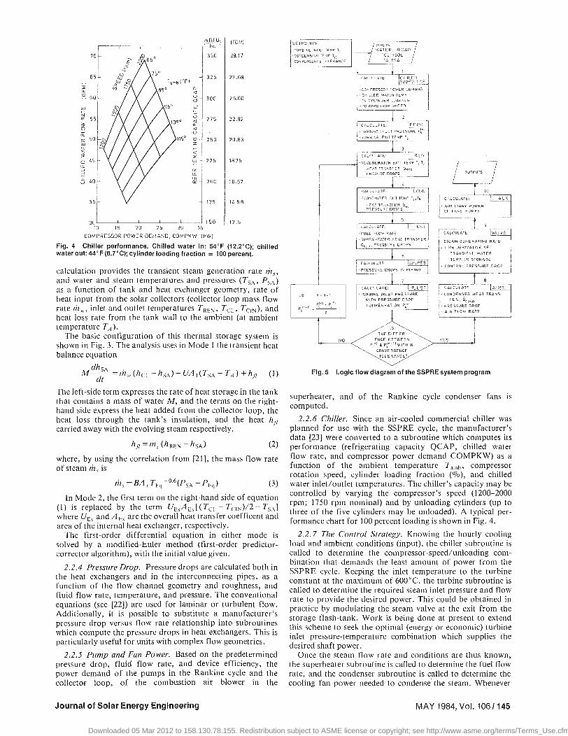
To attain basic understanding of the process, the transient energy interactions and temperatures were examined. Figure 7(a) shows the hourly values for a typical day in Washington, D . C , and Fig. 1(b) is for Phoenix, Arizona. The shown hourly cooling load and sum of energy flows from the fuel, the storage tank and the parasitic and backup electric energy, also allow the easy determination of the hourly or averaged overall system COP. Figure 1(b) shows that the backup motor was engaged between 13:00 and 15:00.
Figure 8(a,b) shows the variations of the temperature and total energy in the storage tank on a typical day. The decrease of stored thermal energy corresponds to the heat extraction from the storage during the system's normal operation. In Fig. 8(b) it can be seen that the tank restores its temperature and total energy between 13:00 and 15:00, when the backup motor is in operation.
Figures 9(a,b) and I0(a,b) show the daily results for a typical week and reflect the fact that there is no cooling load in the office building on weekends, during which time the thermal storage is recharged by continuing collection of solar energy.
The seasonal energy inputs and load are shown, month by
f ^ H t . 0 6 1 BAR
T 5 = 1 0 2 ° C
d r V 0.002 BAH
3 — •
7
U"" 2
REGENERATOR
AftrO.OOaEttR
dpt = O.0O2 BAR
ECONOMIZER
ARi»0-pO2&«
AfV*0\008BAR
Tz = 1l'<.
T4
4
8
l
P, = J
F
1
•LOSS &*R =» 2 5 6 eC
Suf^ f lMEATEn
flPgjp=O.Oj3B^
\ A A A V
5
Pg » 0.14 2 BAR
T e E 3 3 6 C
d f c * 0.O24- BAR
7 5 = 6 0 0 ^
£%>. 0-0044 8 AR
TURBINE
6
PUMP
\ + 05 BAR / TC J
" o = 4 6 °C
0
v w v
• t
Ffeao.i'4 » A "
£Ffc= 0-0)3 BAR
CONDENSER
R = a 3 5 hchmrER
Fig. 6 Typical steam temperature, pressure, and pressure-drop (through the heat-exchangers and a total 3 m equivalent length of 2.5-in.-i.d. pipe)
Sun Master DEC8A, all data according to [25] A unit like this was built to the University of Pennsylvania specifications by
Trane Thermal Co., Conshohocken, Pa.
Journal of Solar Energy Engineering MAY 1984, Vol. 106/147
Downloaded 05 Mar 2012 to 158.130.78.155. Redistribution subject to ASME license or copyright; see http://www.asme.org/terms/Terms_Use.cfm
TYPOWER+TYMOT+TYCHIL [TYMOT+TYCHIL+TYAUX J - +THFUEL
0.31] 0.31]mo,Of .. ZSAV =(100070)------------------"-----------
TYPOWER + TYMOT + TYCHIL
0.31]mo,or
[TYPOWER - TYAUX -- 0.31]010tor THFUEL I =(100070) TYPOWER+TYMOT+TYCHIL (24)
The electric energy saving: For an economic analysis, which compares the energy cost
of an electrically driven chiller with that operated by the SSPRE system, only the electric energy saving (EES) needs to be evaluated against the fuel consumption in the superheater (THFUEL).
.. EES = used by motor-driven [
Total electric energy J
3 Results
chiller system
[
Total electric energy 1 - used by SSPRE
system
TYPOWER + TYMOT + TYCHIL
YJmowr
TYMOT + TYCHIL + TYAUX
YJmotor
TYPOWER - TY AUX
l1motor
(25)
3.1 Conditions and Configuration for the Runs. Hourly weather, insolation, and cooling load data for a small office building with a 25-ton nominal cooling load were obtained from a SERI tape [24] and runs were performed for a 4-month (May-August) cooling season for two different climatic regions. Washington D.C. was selected to represent a Northeastern city which has moderate sunshine (64 percent summer sunshine) and moderate cooling load (1080 annual cooling hrs). The Phoenix commerical load represents the high end for a Southwestern city, with the highest percentage of summer sunshine (84 percent) and the largest number of cooling hours (2750 annually).
The "base-case" system configuration consisted of 37 m3
water for storage, a regenerator having a heat transfer area of 14.9 m2 , an economizer with a finned area of 17.6 m2 , and an air-cooled condenser with a finned area of 763 m2 (31.8 m 2
for the tubes alone). 200 m2 of solar collectors characterized by the equation 3
1]coll = 0.391 4.579 ( T; ~ Ta ) (26)
where the slope is in (kJ/hr m2 0c), were used. The collector has the following incidence angle modifier KaT
Angle of incidence deg
o 15 30 45
1.000 1.070 1.130 1.104
The superheater is gas-fired and has a heat transfer area of
Master DEC8A. all data according to [25]
Journal of Solar Energy Engineering
0.73 m 2 in a parallel-flow furnace section, and 4.23 m2 in a counterflow convection section4
•
The chiller was described in Section 2.2.6. A relief-valve subroutine in TRNSYS was used to limit the
temperature in the storage tank to a maximum of 130°C.
3.2 Transient Performance. To demonstrate a typical set of operating conditions, the temperatures, pressures, and pressure-drops for one of the runs are shown in Fig. 6. It is noteworthy that the pressure drops reduce the available steam pressure ratio across the turbine by 9.3 percent, and thus reduce the power output by a similar percentage. This effect was seldom, if ever, considered in past analyses but, as shown here, should not be ignored.
To attain basic understanding of the process, the transient energy interactions and temperatures were examined. Figure 7(a) shows the hourly values for a typical day in Washington, D.C., and Fig. 7(b) is for Phoenix, Arizona. The shown hourly cooling load and sum of energy flows from the fuel, the storage tank and the parasitic and backup electric energy, also allow the easy determination of the hourly or averaged overall system COP. Figure 7(b) shows that the backup motor was engaged between 13:00 and 15:00.
Figure 8(a,b) shows the variations of the temperature and total energy in the storage tank on a typical day. The decrease of stored thermal energy corresponds to the heat extraction from the storage during the system's normal operation. In Fig. 8(b) it can be seen that the tank restores its temperature and total energy between 13:00 and 15:00, when the backup motor is in operation.
Figures 9(a,b) and lO(a,b) show the daily results for a typical week and reflect the fact that there is no cooling load in the office building on weekends, during which time the thermal storage is recharged by continuing collection of solar energy.
The seasonal energy inputs and load are shown, month by
1', "1.061 BAR T5 =102. gc
.6 f1l; .. 0.002 8M
-,~~~-+~-F~,~A/ Ps-=-1-0133 BAR
T,=600't A~Do.00+4BAR
P7=O.06f3AA
T,~ 162'c llPy :::0.017 BAR
Pz = 1.02
T2=~L'G
ECONOMIZER
% .. 0.14 2. BAR T6"~36 C LIp!, ... o.o~4 BAR
TURBINE
CO"",""R
Fig. 6 Typical steam temperature. pressure, and pressure·drop (through the heat-exchangers and a total 3 m equivalent length of 2.5· in.-Ld. pipe)
unit like this was built to the University of Pennsylvania specifications by TraneThcrmal Co., Conshohocken. Pa.
MAY 1984, Vol. 106/147
TYPOWER+TYMOT+TYCHIL [TYMOT+TYCHIL+TYAUX J - +THFUEL
0.31] 0.31]mo,Of e ZSAV =(100%)---------------------------------------~-----------------
TYPOWER + TYMOT + TYCHIL
0.31]mo,or
[TYPOWER - TYAUX -- 0.31]010tor THFUEL I =(100070) TYPOWER+TYMOT+TYCHIL (24)
The electric energy saving: For an economic analysis, which compares the energy cost
of an electrically driven chiller with that operated by the SSPRE system, only the electric energy saving (EES) needs to be evaluated against the fuel consumption in the superheater (THFUEL).
.. EES = used by motor-driven [
Total electric energy J
3 Results
chiller system
[
Total electric energy 1 - used by SSPRE
system
TYPOWER + TYMOT + TYCHIL
YJmowr
TYMOT + TYCHIL + TYAUX
YJmotor
TYPOWER - TY AUX
l1motor
(25)
3.1 Conditions and Configuration for the Runs. Hourly weather, insolation, and cooling load data for a small office building with a 25-ton nominal cooling load were obtained from a SERI tape [24] and runs were performed for a 4-month (May-August) cooling season for two different climatic regions. Washington D.C. was selected to represent a Northeastern city which has moderate sunshine (64 percent summer sunshine) and moderate cooling load (1080 annual cooling hrs). The Phoenix commerical load represents the high end for a Southwestern city, with the highest percentage of summer sunshine (84 percent) and the largest number of cooling hours (2750 annually).
The "base-case" system configuration consisted of 37 m3
water for storage, a regenerator having a heat transfer area of 14.9 m2 , an economizer with a finned area of 17.6 m2 , and an air-cooled condenser with a finned area of 763 m2 (31.8 m 2
for the tubes alone). 200 m2 of solar collectors characterized by the equation 3
1]coll = 0.391 4.579 ( T; ~ Ta ) (26)
where the slope is in (kJ/hr m2 0c), were used. The collector has the following incidence angle modifier KaT
Angle of incidence deg
o 15 30 45
1.000 1.070 1.130 1.104
The superheater is gas-fired and has a heat transfer area of
Master DEC8A. all data according to [25]
Journal of Solar Energy Engineering
0.73 m 2 in a parallel-flow furnace section, and 4.23 m2 in a counterflow convection section4
•
The chiller was described in Section 2.2.6. A relief-valve subroutine in TRNSYS was used to limit the
temperature in the storage tank to a maximum of 130°C.
3.2 Transient Performance. To demonstrate a typical set of operating conditions, the temperatures, pressures, and pressure-drops for one of the runs are shown in Fig. 6. It is noteworthy that the pressure drops reduce the available steam pressure ratio across the turbine by 9.3 percent, and thus reduce the power output by a similar percentage. This effect was seldom, if ever, considered in past analyses but, as shown here, should not be ignored.
To attain basic understanding of the process, the transient energy interactions and temperatures were examined. Figure 7(a) shows the hourly values for a typical day in Washington, D.C., and Fig. 7(b) is for Phoenix, Arizona. The shown hourly cooling load and sum of energy flows from the fuel, the storage tank and the parasitic and backup electric energy, also allow the easy determination of the hourly or averaged overall system COP. Figure 7(b) shows that the backup motor was engaged between 13:00 and 15:00.
Figure 8(a,b) shows the variations of the temperature and total energy in the storage tank on a typical day. The decrease of stored thermal energy corresponds to the heat extraction from the storage during the system's normal operation. In Fig. 8(b) it can be seen that the tank restores its temperature and total energy between 13:00 and 15:00, when the backup motor is in operation.
Figures 9(a,b) and lO(a,b) show the daily results for a typical week and reflect the fact that there is no cooling load in the office building on weekends, during which time the thermal storage is recharged by continuing collection of solar energy.
The seasonal energy inputs and load are shown, month by
1', "1.061 BAR T5 =102. gc
.6 f1l; .. 0.002 8M
P7=O.06f3AA
T,~ 162'c llPy :::0.017 BAR
Pz = 1.02
T2=~L'G
ECONOMIZER
% .. 0.14 2. BAR T6"~36 C LIp!, ... o.o~4 BAR
Ps-=-1-0133 BAR
T,=600't A~Do.00+4BAR
TURBINE
CO"",""R
Fig. 6 Typical steam temperature. pressure, and pressure·drop (through the heat-exchangers and a total 3 m equivalent length of 2.5· in.-Ld. pipe)
unit like this was built to the University of Pennsylvania specifications by TraneThcrmal Co., Conshohocken. Pa.
MAY 1984, Vol. 106/147
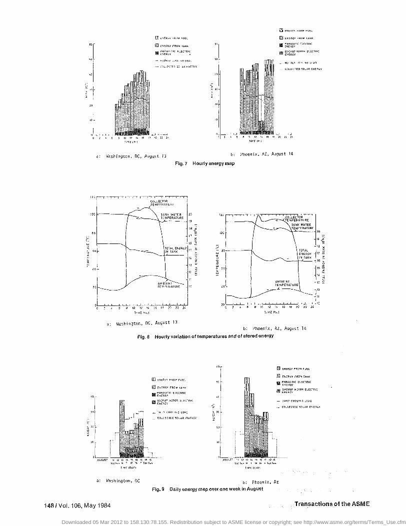
H EM ERGY FROM FUEL
I ENERGY FROM I
I ENERGY FROM TANK
HOURLY COOLING LOAD
• COllECIEO SOLAR ENERGY HOURLY COOLING LOAD
COLLECTED SOLAR ENERGY
S 20 22 2i 2 i 6 3 20 22 24 TIME (ht.)
Washington. DC, August 13 b- Phoenix, AZ, August 14
Fig. 7 Hourly energy map
80
60
40
20
•••» | i T - ' 1' ' 1 ' I ' 1 ' i ' 1 ' 1 ' 1 ' 1 ' 1
COLLECTOR .TEMPERATURE
"!*"", S ^v
' "" " " — ^ L _ \ I^HK YVAIfcK -/ ^ r r r _ _ \ TEMPERATURE
-
-
\
\ ITOTAL ENERGY ^~~—-=~_^_^ UN TANK
1
— f AMBIENT^--—, ' TEMPERATURE
2 4 S 8 19 !2 H 1& 18 20 22 24
TIME |hr.)
a: Washington, DC, August 13
100
°~ 80 or 3
o:
o. 60
-40
• t • i • i ' A ' ' COLLECTOR ' / V _ ^ - =^=»<TEMPERATURE
/C \ TANK WAFER / ^ ~\\TEMPERATURE i *^~-
'
\ TOTAL \ I ENERGY -
AMBIENT TEMPERATURE
™
" .
' "̂ J~~~"^
iO n K 36 Jfl 20 22 24
TIME (hr.)
b: Phoenix, AZ, August 14
Fig. 8 Hourly variation of temperatures and of stored energy
I ENERGY FROM FUEL
j ENERGY FROM
. DAILY COOLING LOAD
. COLLECTED SOLAR ENERGY
~1
I ENERGY FROM FUEL
I ENERGY FROM JAN
DAILY COOLING LOAD
COLLECTED SOLAR ENERGY
!S 19 T W Th F Sol Sun
ME (DAYI
a: Washington, DC b . p h o e n i x , Az
Fig. 9 Daily energy map over one week in August
148/Vol. 106, May 1984 Transactions of the ASME
Downloaded 05 Mar 2012 to 158.130.78.155. Redistribution subject to ASME license or copyright; see http://www.asme.org/terms/Terms_Use.cfm
50
20
10
'20
'00
ao u
w
'" ~ ~
60
w ~
:> ~
'0
20
0
40
30
'0
iillfI ENERGY FROM FUEL
UIJJ ENERGY FROM FUEL rn ENERGY FROM TANK
t&.J ENERGY FROM TANK II ~~:~g~71c ELECTRIC
II ~~~:g~TIC ElECTRI~ III ~~~~~~ MOTOR ELECTRIC
- HOURLY COOLING LOAO
••• COllECTED SOLAR ENERGY
e 10 12 " 16 182022 2L flME /lui TIME In,1
a: Washington, DC, August 13
COLLECTOR ;TEMPERATURE
b: Phoenix, AZ, August 14
Fig. 7 Hourly energy map
20 '20
,9
,a 0 '00 20
,1
" z '6 :;
19 w~
;~T~~N~NERGY IS u
" r
" w
" '" '" W ~
z
~ 13 w
:; 12 :>
"' ~ 11
'0
80
60
'0
AMBIENT TEMPERATURE
'a TOTAL ENERGY 17 IN TANK
16
15
" 13
12
11
20 ~~~~~~~~~~~~~J-~~LJ'O
0
a:
8 '0 " " '6 " 2D 22 " 0 8 10 12 I' 16 18 20 22 2'
TIME \lu.\ T!ME {h!.\
Washington, DC, August 13 b: Phoenix, AZ, August 14
Fig. 8 Hourly variation of temperatures and of stored energy
I!I!!I ENERGY FROM FUEL
~ ENERGY FROM lANK
II ~~~~~IJIC ELECTRIC
Ii! ~~~~~~ MOTOR ELECTRIC
_ DAILY COOLING LOAD
•.• COllECTED SOLAR ENERGY
60
50
~ 30
rnn ENERGY FROM FUEL
rn ENERGY FROM lANK
fiI ~~~AR~I~IC ELECTRIC
IS ~~~~~~ MOTOR ELECTRIC
_ DAilY COOliNG LOAD
COllECTED SOLAR ENERGY
AUGUST 11 12 13 '4 15 16 17 18 19 Sal Sun M T W Til F Sal Sun
AUGUST 11 11 1) 14 15 Hi !1 18 19 Sat Sun M T W Th F Sal Sun
TIME (DAY I TIME (OAYI
a: Washington, DC b: Phoenix, Az Fig.9 Oally energy map over one week in August
" z ;0
'" >
~ z w
;t §
1481 Vol. 106, May 1984 Transactions of the ASME
- JO
. 20
10
0 0
'20
'00
ao u
w
'" ~ ~
60
w ~
:> ~
'0
20
0
4Q
JO
10
iillfI ENERGY fROM FUEL
UIJJ ENERGY FROM FUEL rn ENERGY FROM TANK
t&.J ENERGY FROM TANK II ~~:~g~71c ELECTRIC
II ~~~:g~TIC ELECTRI~ III ~~~~~~ MOTOR ELECTRIC
- HOURLY COOLING LOAD
_.- COlLECTED SOLAR ENERGY
e 10 12 " 16 182022 lL
flME /lui
so
~ lO
10
B 10 12 I' 16 18 M 22 2' TIME In,1
a: Washington, DC, August 13 b: Phoenix, AZ, August 14
Fig. 7 Hourly energy map
COLLECTOR ;TEMPERATURE
20 '20
,9
,a 0 '00 20
,1
" z '6 :;
19 w~
0
a:
AUGUST
;~T~~N~NERGY 15
" 13
12
11 AMBIENT TEMPERATURE '0
8 '0 " " '6 " 2D 22 " TIME \lu.\
Washington, DC, August 13
.u
" 80 r
" w
'" '" W ~
z
~ w
:; 60 :>
"' ~
'0
20
AMBIENT TEMPERATURE
TOTAL ENERGY IN TANK
'a 17
16
15
" 13
12
11
L...c--!-'-'-~!-'---'8:-'-""O~'':-2 -'---'''~''''6~'8LLc'2D~2.:':2~2LJ, '0 0
1!ME {h!.\
b: Phoenix, AZ, August 14
Fig. 8 Hourly variation of temperatures and of stored energy
TIME (DAY I
I!I!!I ENERGY FROM FUEL
~ ENERGY FROM lANK
II ~~~~~IJIC ELECTRIC
Ii! ~~~~~~ MOTOR ElECTRIC
_ DAILY COOLING LOAQ
•.• COllECTED SOLAR ENERGY
FSatSVfl
60
so
La
~ 30
Sut Sun M T W Th F SuiSun
TIME (DAY I
rnn ENERGY FROM FUEL
rn ENERGY FROM lANK
fiI ~~~AR~I~IC ELECTRIC
IS ~~~~~~ MOTOR ELECTRIC
_ DAilY COOLING LOAD
COllECTED SOLAR ENERGY
a: Washington, DC b: Phoenix, Az Fig.9 Oally energy map over one week in August
" z ;0
'" >
~ z w
;t §
1481 Vol. 106, May 1984 Transactions of the ASME

_ J TOTAL ENERGV J l N TANK AT THE
" E N D OF THE DAY
r—' HIGHEST J A M 8 I E N T TEMPERATURE
IN THE DAY
AUGUST 11 12 13 H 15 16 17 16 19 Sat Sun M T W Th F Sal Sun
TANK WATER TEMPERATURE AT THE END OF THE DAY
TOTAL ENERGY IN TANK AT THE END OF THE DAY
HIGHEST AMBIENT TEMPERATURE IN THE DAY
AUGUST it 12 13 K 15 16 17 16 19 Sat Sun M T W Th F Sat Sun
a: Washington, DC b: Phoenix, AZ
Fig. 10 Daily variaton in storage tank temperature and energy at the end of the day, and in peak daily ambient temperature, for one week in August
I ENERGY FROM FUEL
I ENERGY FROM TANK
MONTHLY COOLING LOAD
. COLLECTED SOLAR ENERGY
r i
I ENERGY FROM FUEL
I ENERGY FROM TANK
-*. MONTHLY COOLING LOAO
. . . COLLECTED SOLAR ENERGY
a: Washington, DC
TIME (MONTH)
b: Phoenix, AZ
Fig. 11 Monthly energy map for a cooling season
AUG. SEASONAL 66.6V.RANKINE ENGINE CONTRIBUTION
. MONTHLY COOLING LOAD
*6 S i 92 52 • 8ACKUP MOTOR OPERATING HOURS
_m AVG. SEASONAL | 72.7 V. RANK (HE
ENGINE CONTRIBUTION
22 66 50 53'. BACKUP MOTOR OPERATING HOURS
TIME IMONIHI
a: Washington, DC b: Phoenix, AZ
Fig, 12 Monthly cooling load satisfied by the SSPRE, for a cooling season
Journal of Solar Energy Engineering MAY 1984, Vol, 106/149
Downloaded 05 Mar 2012 to 158.130.78.155. Redistribution subject to ASME license or copyright; see http://www.asme.org/terms/Terms_Use.cfm
50
50
"
~ 30
20
10
so
o . 330
" z
o o
~ 20
r
z o >:
'0
120
100
80 u
w ~
=>
~ 50
>: !"
"
20
~
l' ~R ~ WJ~~~A~~~~ AT THE END OF THE DAY
~l~~ ~ AM8IE'N'T TE MPERATURE
IN THE DAY
AUGUST 11 12 13 14 15 16 17 18 19 Sat Sun M T W Th F Sat Sun
TIME (DAY I
~ 20 ~
19 ~
18 ~
17 ~
16 4.
IS ~ ~o
" -~ z
13 ~
12 t: i';
11 ~ 10
w
'" =>
'40 r--------------,
120
100
~ w r
~ o
20 ~
19 * 18 ';.i
~ 80 17"h 16 i
w n.
~ 60
~ !5~
HIGHEST AMBIENT lEMPERA1URE 14 ~ IN THE DAY 13 ~
20 LA:CU-::GCCUC::5':--'-:'-:-' L,-=-, L,-=-, ':,-:-. '-:'-=-5 '-:,::, '-:'::7 .L,::,'-:,::,-'---' '0 Sat Sun M T W Th F Sa! Sun
II ME (DAY!
a: Washington. DC b: Phoenix. AZ
Fig. 10 Daily variaton in storage tank temperature and energy at the end of the day, and in peak daily ambient temperature, for one week in August
(J]] ENEROY FROM FUEL
~ ENERGY FROM TANK
1'1 PARASitiC ELECTRIC ENERGY
mI BACKUP MOTOR ELECTRIC ENE ROY
_ MONTHLY COOLING LOAD
.~_ COt.lEC1ED SOLAR EHERGY
"
70
60
so
40
30
20
'0
MAY JUN JUL AUO
TIME (MONTH!
IDIII ENERGY FROM FUEL
g] ENERGY FROM TANK
&I ~~~~~~TIC ELECTRIC
II ::~=~~ MOTOR ELECTRIC
__ MONTHLY COOLING LOAD
___ COLLECTED SOLAR ENERGY
a: Washington, DC b: Phoenix, AZ
Fig. 11 Monthly energy map for a cooling season
70
_ MONTHLY COOUNG LOAD
M~'( JUH JUl AUG MAY jUt{ JUl tl.UG
AVO, SE A50NAl
~ ~~'~~~ER~~~;~;8UlION
__ MONTHLY COOLING
LOAD
45 54 92 52: BACKUP MOTOR OPERATING HOURS 22 55 50 53: BACKUP MOTOR OPERATiNG HOURS
a: Washington,
Fig. 12 season
TIME (MOtHH!
DC b: Phoenix, AZ
Monthly cooling load satisfied by the SSPRE, for a cooling
Journal of Solar Energy Engineering MAY 1984, Vol. 1061149
50
20
10
so
" ~ 330
" z
g ~ 20
r
z o >:
120
100
80 u
w ~
=>
~ 50
>: !"
"
20
~
l' ~R ~ WJ~~~A~~~~ AT THE END OF THE DAY
~l~~ ~ AM8IE'N'T TE MPERATURE
IN THE DAY
AUGUST 11 12 13 14 15 16 17 18 19 Sat Sun M T W Th F Sat Sun
TIME (DAY I
~ 20 ~
19 ~
18 ~
17 ~
16 4.
IS ~ ~o
" -~ z
13 ~
12 t: i';
11 ~ to
w
'" =>
'40 r--------------,
120
100
~ 80
w n.
~ 60
HIGHEST AMBIENT lEMPERA1URE IN THE DAY
~ w r
~ o
20 ~
19 * 18 ';.i
17"h 16 i
~ !5~
14 ~
13 ~
12 ;t S
11 ~
20 LA-CUC:GCCUS"'T=-'-C':-" -12~I3~"~'S::-'-c"~'-::-7 L,CC, ~'-:-9 <----l,0
Sat Sun M T W Th F Sa! Sun
II ME (DAY!
a: Washington. DC b: Phoenix. AZ
Fig. 10 Daily variaton in storage tank temperature and energy at the end of the day, and in peak daily ambient temperature, for one week in August
(J]] ENEROY FROM FUEL
~ ENERGY FROM TANK
II ~~~~sd~'C ELECTRIC
lit ~~~~~~ MOTOR ELECTRIC
_ MONTHLY COOUNG LOAD
.~_ COt.lEC1ED SOLAR EHERGY
"
70
60
so
40
30
20
'0
MAY JUN JUL AUG
TIME (MONTH!
IDIII ENERGY FROM FUEL
g] ENERGY FROM TANK
&I ~~~~~~TIC ELECTRIC
II ::~=~~ MOTOR ELECTRIC
__ MONTHLY COOLING LOAD
___ COLLECTED SOLAR ENERGY
a: Washington, DC b: Phoenix, AZ
Fig. 11 Monthly energy map for a cooling season
_ MONTHLY COOUNG LOAD
M~'( JUH JUl AUG
50
" ~ 40
~ z
o o u
~ , 20
"
MAY JUN JUL AUG
AVG, SE ASONAL
~ ~~'~~~ER~~~;~;8UlION
__ MONTHLY COOLING
LOAD
46 54 92 52: BACKUP MOTOR OPERATING HOURS 22 66 50 53: BACKUP MOTOR OPERATiNG HOURS
a: Washington,
Fig. 12 season
TIME (MOtHHj
DC b: Phoenix, AZ
Monthly cooling load satisfied by the SSPRE, for a cooling
Journal of Solar Energy Engineering MAY 1984, Vol. 1061149

Table 1 Detailed simulation results for the base-case SSPRE/cooling system for a four-month cooling season
Parameter
TFUEL
THFUEL
TVAOX
TYCHIL
THPFAli
TPOWER
Twzm
TOTAL
TVPOMER
TrKOT
TV50L
TRAD
THLOAD
RLOAD
NLOAO
TPWKAX
7YTAUK
TQSUP
TQREG
TQEC
TQCOK
TQIOSS
TQOVER
e r
cc
RC
CL
fi
U n i t s
kg
10 6kJ
[ < A j
10 6 kJ
h p - h r
h p - h r
h p - h r
h p - h r
106k0
N>6|cJ
30 6kJ
106k0
1 0 ' k J
10 6kJ
106kJ
h p - h r
10 6kJ
106kJ
} 0 6 k J
left,) l e f t J
10 6kJ
10 6kJ
% %
May
189.9
9.517
0.781
3.437
224.9
2103
1321
3424
5.648
3.548
25.95
102.74
16.56
13.24
3.325
2860
26.19
7.402
4 .500
1.714
28 .45
0 .876
0
76 .9
67 .2
70 .0
61 .42
79.92
46
Washing
June
199.3
9.981
0.631
3.762
160.4
2180
1067
3247
5.855
2.866
29 .72
119.60
33.38
23.58
9.797
2996
29.02
7.835
5.460
1.907
31 .56
0.823
0
78.2
68 .0
72 .0
67 .39
70.55
54
t o n , OC
J » J r _
257.1
3.752
0.635
3.762
159.6
1869
1890
3759
5.020
5.076
25.71
100.00
45 .03
23.65
21.380
2581
24.88
6.812
4 .592
1.689
27.17
0.788
0
76.7
67 .3
70.7
49.72
52.23
92
August
233.8
11.710
1.004
3.762
301.8
2479
1387
3866
6.658
3.725
31 .17
111.30
45 .52
33.02
12.500
3423
32.83
9.066
5.971
2.250
35.87
0.829
0
76 .0
66 .9
69 .8
64.12
72.54
52
T o t a l
830 .1
39.960
3.051
14.720
846.7
8631
5665
14296
23.180
15.210
112.55
433.60
140.50
93 .49
47.000
11860
112.90
31.120
20.520
7.560
123.06
3.316
0
76 .9
67 .3
70.6
60.37
66 .55
244
May
313.7
15.72
0.562
3.728
31 .90
2956
797.1
3753
7.939
2.141
47 .89
161.7
40.99
36.03
4 .96
4053
44 .12
11.83
8.576
3.264
48.41
0.908
0
74 .0
65 .4
72.7
78.76
87 .90
22
Phoeni*
June
316.0
15.83
0.617
3.762
77.75
2836
2576
5412
7.616
6.918
42 .57
148.3
55.69
38.79
16.90
3878
39.84
11.43
6.856
3.088
44 .03
0.910
0.108
69 .3
6 2 . 6
70.7
52.40
69 .65
66
, A7
J u l y
254.0
12.73
0.589
3.728
89 .32
2222
3375
5597
5.967
9.064
40 .36
144.0
61.46
47 .95
13.51
3032
30 .80
9.03
5.070
2.430
34.06
0 .946
3.828
67 .3
61 .3
6 9 . 0
39 .70
78.02
50
August
341.2
17.10
0.724
3.762
120.80
3016
2728
5744
8.100
7.326
46 .20
158.2
61.32
36.89
24.43
4114
41.11
12.14
6.650
3.221
45.43
0.932
0.892
67 .2
61 .2
69 .0
52.51
60 .16
53
T o t a l
1224.5
61 .38
2.492
14.980
319.77
11030
9476.1
20506
29.620
25.450
177.02
612.2
219.50
159.66
59.80
15077
155.87
44.70
27.152
12.000
171.93
3.696
4.823
69.8
62.7
70.5
53.79
72.73
191
month, in Fig. \l(a,b), and the cooling load satisfied by the SSPRE is shown in Fig. \2{a,b). 66.6 percent of the total seasonal cooling load is satisfied by the SSPRE in Washington, D.C. and 72.7 percent in Phoenix, Arizona. Listed below the monthly bars in Fig. 1 \(a,b) are the monthly operating hours of the backup motor.
3.3 Seasonal Performance. The seasonal performance of the system in the "base-case" configuration is summarized in Tables 1 and 2. Several observations are noteworthy:
• As expected, when the electric energy used by the backup motor is included in the definition of the system COP, the fact that the efficiency of conversion of electric energy to cooling is higher than that of thermal energy to cooling make the COP increase with the fraction of the total energy supplied by this motor and may thus be misleading for evaluating solar-powered systems.
• The seasonal efficiency of the power cycle remains about double that of organic fluid cycles operating at similar solar collector temperatures.
• The COP of this base-case configuration is similar to or better than other solar cooling systems operating with the same collectors, chiller, and air-cooling (see [26, 27]).
• Although the needed collector investment in the SSPRE/cooling system is significantly lower than that for other solar cooling systems, the savings in electric energy consumption (and cost) in this "base-case" configuration are rather modest and reflect the economic weakness characteristic to existing solar cooling system in general.
3.4 Improved System Configurations. To examine the potential improvement of the system's performance, simulation runs were made for the month of August in Phoenix, Arizona, where the "base-case" configuration was altered by replacing the evacuated collectors with higher efficiency flat-plate ones, and the air-cooled power-cycle condenser by a water-cooled one.
Three cases with following configurations were studied:
• Case 1: The "base-case" evacuated-tube collector (see section 3.1) with a water-cooled power-cycle condenser.
Table 2 Major results for the four-month simulation (May-August) of the base-case SSPRE/cooling system
Tota l Resource Energy used, (10 k J ) :
So la r Energy
Fuel Energy
E l e c t r i c Energy
Energy F rac t ions
So la r Energy
Fuel Energy
E l e c t r i c Energy
To ta l
ZE:
RC p a r a s i t i c
C h i l l e r p a r a s i t i c
Back-up motor
% C o n t r i b u t i o n o f Rankine Cycle
To To ta l Cool ing Load
To To ta l Power Demand
C o l l e c t o r E f f i c i e n c y
Thermal E f f i c i e n c y o f
Rankine Cycle
Overa l l Rankine Cycle
E f f i c i e n c y
Rankine Cycle Resource
E f f i c i e n c y
C h i l l e r COP exc lud ing
Condenser Fan
C h i l l e r COP w i t h
Condenser Fan
Overa l l System COP based on
Tota l energy i n p u t
Resource energy i npu t
Net energy convers ion
Thermal energy i n p u t
% Resource Energy Saving
E l e c t r i c Energy Saving (10 kJ} (kW-hr)
TYS0L
THFUEL
E/oe
ZS0L
ZFUEL
ZE
ZAUX
ZCHIL
ZH0T
iSCL
SRC
" c o l l
ZRANK
0ZRANK
0ZRANR
C0PNF
COP
0C0PP
0C0PR
0C0PS
0C0PT
ZSAV
EES
Washington, DC
112.6
39.96
32 .98 /0 .3
42.9%
15.2%
41.9?
100%
3 . 9 *
18.7%
19.3%
66.5% 60.4%
0.260
0.158
0.149
0.142
3.66
2.65
0.757
0.627
0.877
0.649
22.1%
28.76
(7989)
Phoenix, AZ
177.02
61.38
4 2 . 9 J / 0 . -
46.4%
16.1%
37.516
100%
2.2%
13. n
22.2%
72. 7%
53.8%
0.289
0.146
0.135
0.131
3.99
3.13
0.780
0.575
0.967
0.796
20.35;
38.75
(10764)
• Case 2: Higher-efficiency flat plate collector, with the "base-case" air-cooled power-cycle condenser.
• Case 3: Higher-efficiency flat-plate collector with a water-cooled power-cycle condenser.
To simplify the analysis, and since only an upper bound was sought for the improvements, it was assumed that the
150/Vol. 106, May 1984 Transactions of the ASME
Downloaded 05 Mar 2012 to 158.130.78.155. Redistribution subject to ASME license or copyright; see http://www.asme.org/terms/Terms_Use.cfm
Table 1 Detailed simulation results for the base·case SSPRE/cooling system for a four· month cooling season
Washington, DC Phoenix.
1 __ ~~~~~~,~~+~M~'~~J"~ne. __ ~~~l~~A~"~"~st~T~o~t'~l~.~L-.~~ ___ ~CL-~~~_~~ __ ~ 1:;g 189.9 199.3 257.1 233.8 880.1 313.7 316.0
THFUEL 106
kJ 9.517 9.981 3.752 11.710 39.960 15.72 15.83
HAUX l06kJ 0.781 0.631 0.635 1.004 3.051 0.5620.617
TYCHIL 106kJ 3.437 3.762 3.762 3.762 14.720 3.728 3.762
THPFAr! hp-hr 224.9 160.4 159.6 301.8 846.7 31.90 77,75
TPOWER
TPwr-',or
TOTAL
TYPOWER
TY/I.oT
TYSOL
TRAD THlOAD
RlOAQ
!>',lOAD
TPWt-lAX
TYTANK
TQSUP
TQREG
TQEC
TQCON
TQlOSS
TQOVER
hp-hr 2103 2180
tJp-hr 132'1 1067
hp-hr 3424 3247
106kJ 5.648 5.855
3,548 2,866
25.95 29.72
102.74 119.60
16.56 33.38
13.24 23.58
3.325 9.797
2860 2996
26.19 29.02
7.402 7.835
4,500 5.460
1. 714 1.907
28.46 31.56
0.876 0.823
76.9 78.2
67.2 68.Cl
70.0 72.0
61.42 67.19
79.92 70,1)5
46 54
1869 2479 8631 2956 2836
J890 1387 5665 797. J 2576
3759 3866 14296 3753 5412
5.020 6.65823.180 7.9397.616
5.076
25,71
100.00
45.03
23.65
2).380
2581
24.88
6.812
4.592
1.689
27.17
0,788
76.7
3.725 15.210
31. 17 112.55
111.30 433.60
45.52 140.50
33.02 93.49
12,500 47.000
3423 11860
32,83 112,90
9.066 31.120
5.971 20.520
2.250 7.560
35.87 123.06
0.B29 3,316
o 0
76.0 76.9
2.141 6.918
47,89 42.57
161,7 148.3 144,0
40.99 55.69 61.46
36.03 38.79 47.95
4.% 16,90 13.51
4053 3878 3032
44.1( 39.84 30.80
11.83 11.43 9.03
8.516 6.856 5.070
3.2M 3.088 2.430
48.41 44.03 34.06
a.908 0.910 0.946
0.108 3.828
74.0 69.3 67.3
46.20
158.2
61.32
36.89
24.43
4114
41.11
12.14
6.650
3.221
45.43
0.932
0.892
67.2
67.3 66.9 67,3 65.4 62.5 61.3 61.2
70,7 69,8 70.6 72.7 70.7 69.0 69.0
49,72 64.12 60.37 78.76 52.40 39.70 52.51
52.23 72.54 66.55 87.90 69.65 78.02 60.16
92 52 244 22 66 50 53
177.D2
612.2
119.50
159.66
59.80
15077
155.87
44.70
27.152
12.000
171. 93
3.696
4.328
69.8
62.7
70.5
53.79
72.73
191
month, in Fig. ll(a,b), and the cooling load satisfied by the SSPRE is shown in Fig. 12(a,b). 66.6 percent of the total seasonal cooling load is satisfied by the SSPRE in Washington, D.C. and 72.7 percent in Phoenix, Arizona. Listed below the monthly bars in Fig. II (a,b) are the monthly operating hours of the backup motor.
Table 2 Major results for the four·month simulation (May·August) of the base·case SSPRE/cooling system
3.3 Seasonal Performance. The seasonal performance of the system in the "base-case" configuration is summarized in Tables I and 2. Several observations are noteworthy:
$ As expected, when the electric energy used by the backup motor is included in the definition of the system COP, the fact that the efficiency of conversion of electric energy to cooling is higher than that of thermal energy to cooling make the COP increase with the fraction of the total energy supplied by this motor and may thus be misleading for evaluating solarpowered systems.
.. The seasonal efficiency of the power cycle remains about double that of organic fluid cycles operating at similar solar collector temperatures.
.. The COP of this base-case configuration is similar to or better than other solar cooling systems operating with the same collectors, chiller, and air-cooling (see [26,27]).
"Although the needed collector investment in the SSPRE/cooling system is significantly lower than that for other solar cooling systems, the savings in electric energy consumption (and cost) in this "base-case" configuration are rather modest and reflect the economic weakness characteristic to existing solar cooling system in general.
3.4 Improved System Configurations. To examine the potential improvement of the system's performance, simulation runs were made for the month of August in Phoenix, Arizona, where the "base-case" configuration was altered by replacing the evacuated collectors with higher efficiency flat-plate ones, and the air-cooled power-cycle condenser by a water-cooled one.
Three cases with following configurations were studied:
.. Case 1: The "base-case" evacuated-tube collector (see section 3.1) with a water-cooled power-cycle condenser.
150 I Vol. 106, May 1984
• Total Resource Energy used. (1 06kJ ):
Solar Energy Fue 1 Energy Electric Energy
Energy Fractions
Solar Energy Fue 1 Energy Electric Energy
Total
ZE: RC paras iti c Chiller parasitic Back-up motor
Contribution of Rankine Cycle
To Total Cool ing Load To Tota 1 Power Demand
Collector Efficiency
Thermal Efficiency of Rankine Cycle
• Overall Rankine Cycle Efficiency
Rankine Cycle Resource Efficiency
Chiller COP excluding Condenser Fan
Ch iller COP with Condenser Fan
Overall System COP based on
Total energy input Resource energy ; nput Net energy conversion Therma 1 energy input
• % Resource Energy Saving
Electric Energy Saving (106kJ ) (kW-hr)
TYSOL THFUEL E/oe
ZSOL ZFUEL ZE
ZAUX ZCHIL ZMOT
%Cl %RC
f"lcoll
ZRANK
OZRANK
OZRANR
COPNF
COP
OCOPP OCOPR OCOPS OCOPT
ZSAV
EES
Washington, DC
112.6 39.96 32.98/0.3
42.9% 15.2% 41. 9%
100%
3.9% 18.7% 19.3%
66.5% 60.4%
0.260
D. J58
0.149
0.142
3.66
2.65
0.757 0.627 0.877 0.649
22.1%
28.76 (7989)
Phoenix~ AZ
177 .02 61.3a 42.92/0.3
46.4% 16.1% 37.5%
100%
2.2% 13.1% 22.2%
72.7Z 53.8%
0.289
0.146
0.135
0.131
3.99
3.13
0.780 0.575 0.967 0.796
20.3%
38.75 (10764)
" Case 2: Higher-efficiency flat plate collector, with the "base-case" air-cooled power-cycle condenser.
.. Case 3: Higher-efficiency flat-plate collector with a water-cooled power-cycle condenser.
To simplify the analysis, and since only an upper bound was sought for the improvements, it was assumed that the
Transactions of the ASME

steam condensation temperature in the water-cooled condenser is the ambient dry-bulb temperature as read on an hourly basis from the meteorological data for Phoenix in August. For a similar reason, the incidence angle modifier of the higher-efficiency collector KaT, was assumed to be unity. The collector's efficiency equation was5
i j c o „ = 0 . 7 8 - 1 4 . 1 9 ( ^ ^ ) (27)
where the slope is in (kJ/hr m2 °C). It is noteworthy that the peak efficiency of this collector is twice as high as that of the one described by equation (26), but its slope is about three times higher.
The major results of the runs are compared to those for the "basecase" in Table 3. By reducing the turbine back-pressure, water cooling (Case 1) increases the power cycle efficiency by 23.3 percent, which results also in an increase in the power cycle's contribution for satisfying the cooling load, and in significant increases in the resource energy saving ZSAV (56 percent), and electric energy saving EES (32.4 percent). The observed decreases in the coefficients of performance OCOPS and OCOPP are due to a decrease in the use of the electric backup motor, as explained in section 3.3 above.
In Case 2, the collector's average efficiency is 15.4 percent higher. The Rankine cycle's efficiency, however, remains essentially unchanged, because the top cycle temperature is kept the same (600 °C). Since the thermal storage obtains more energy with these collectors, the Rankine cycle's contribution to driving the compressor increases, and so does the electric energy saving (+18.8 percent).
Combining both water-cooling and the higher-efficiency collectors in Case 3, results in an 85.5 percent increase in resource energy saving (ZSAV) due to the significantly higher contribution of the Rankine cycle, and a 56 percent increase in electric energy saving. The corresponding increase in fuel consumption for the superheater (THFUEL) is only 25.3 percent.
The results in Table 3 also demonstrate that the combined use of water cooling and higher-efficiency collectors provide performance which is better than that obtained by increasing the collector area by 50 percent. For example, the electric energy saving is larger by 15 percent, and the fuel consumption is reduced at the same time by 9 percent.
Further improvements in system performance can be obtained by using a chiller with a higher COP, by reducing the parasitic fan power, and by an optimal system control strategy. The latter is the subject of continuing research at the University of Pennsylvania. The impact of the two former methods can, however, be approximately assessed as follows:
1 Fan power use in the chiller's air-cooled condenser is significant and is calculated by the assumption that all fans are in operation whenever the chiller is on. Normally, however, the fan power would be lower, either by adjusting the fan power to the condensing need, or by better condenser or fan design. If all fan power was eliminated, the chiller performance would have increased by a factor of (COPNF/COP). Seasonally, this is 1.380 for Washington and 1.275 for Phoenix. If, as observed in many commercial installations, only half of the fans are in operation (on the average), the potential improvement factor is 1.19 for Washington and 1.14 for Phoenix, or 1.165 average.
2 In an analysis of a similarly sized chiller by Carrier [26], it was stated that the type of chiller used in the simulation had a seasonal COPNF of 4.7 (when averaged between New York and Phoenix). The chiller simulated here had an average COPNF of 3.8. Using the higher-performance chiller would have thus improved the COPNF by a factor of (4.7/3.8) = 1.24.
5 Corresponding to an Ametek Co. flat-plate collector
Table 3 Relative changes of performance due to the introduction of a higher-efficiency collector and water-cooling of the power-cycle condenser
Col lector Area:
Parameter
%RC
SCL
ncoll
OZRANK
OCOPS
OCOPP
ZSAV
THFUEL
EES
1
+ 25.9
* 20.2
+ 1.6
+ 23.3
- 2.6
+ 0.6
+ 56.2
+ 7.3
+ 32.4
Base-Case Va ,ue' Acoll
Parameter Change,
2
* 17.1
+ 12.2
* 15.4
+ 0
- 12.4
- 10.5
+ 19.6
+ 17.9
+ 18.8
,b
n % fo r Case Number
3
+ 46.5
* 33.5
* 18.6
* 23.3
- 13.2
- 10.3
* 85.5
+ 25.3
+ 56.0
'•5AC0H,i,
3
+ 7.8
+ 6.8
+ 21.5
+ 19.7
• 10.6
+ 19.7
* 38.6
- 9.0
+ 15.0
For the month of August, the overall base-case system COP, including all losses, OCOPP, was 0.85 (as averaged between Phoenix and Washington). Consequently, by a reduction of chiller fan power, and by using a better chiller, the OCOPP may rise to (0.85)(1.165)(1.24) = 1.23.
The use of a water-cooled chiller will result in an additional improvement of — 10 percent, as shown above and in [23]. This may boost the OCOPP to 1.35.
4 Conclusions
• A comuter program was successfully developed for the transient simulation of hybrid solar-powered/fuel assisted power/cooling systems, based on comprehensive modeling of all of the system's components. The program allows easy change of component configuration to evaluate the system's performance sensitivity.
• Based on transient simulation, the seasonal thermal efficiency of the proposed Rankine system with the evacuated tube collector and air-cooled condenser (the base-case) is 15.8 percent in Washington, D.C. and 14.6 percent in Phoenix, Arizona. The thermal efficiency of the Rankine system with the water-cooled condenser (Case 2), is 17.9 percent for the month of August in Phoenix, for both types of collectors considered, as compared to 15.0 percent for the same month with the base-case configuration.
• The overall Rankine cycle seasonal efficiency based on total energy input, including the parasitic power, is 14.9 percent in Washington, D.C. and 13.5 percent in Phoenix for the basecase. By using the water-cooled condenser (Case 2), this value is elevated to 16.5 percent for August in Phoenix (as compared to 13.4 percent for the same month, base case). Again, it is the same for both types of collectors
• The overall system COP based on total net energy conversion, excluding parasitic energy, the seasonal (OCOPS), was found to be 0.88 in Washington, D.C. and 0.97 in Phoenix for the base case (air-cooled condenser, evacuated tube collectors, and a chiller with a seasonal COP = 3.7).
• The overall system COP based on total energy input, OCOPP, in Phoenix is 0.816 for the basecase, 0.82 for Case 1, and 0.73 for Cases 2 and 3. Reduction of the chiller condenser's fan power to the practical value of 1/2 of that assumed in the simulation, the use of a higher performance chiller (COPNF = 4.7 as in [26]), and water cooling can increase the OCOPP to 1.35 (average value between Washington and Phoenix for August). Implementation of a water-cooled condenser and high-quality flat-plate collectors create a performance improvement which is superior to that created hy adding 50 percent more of the evacuated collector area to the base case.
Journal of Solar Energy Engineering MAY 1984, Vol. 106/151
Downloaded 05 Mar 2012 to 158.130.78.155. Redistribution subject to ASME license or copyright; see http://www.asme.org/terms/Terms_Use.cfm
steam condensation temperature in the water-cooled condenser is the ambient dry-bulb temperature as read on an hourly basis from the meteorological data for Phoenix in August. For a similar reason, the incidence angle modifier of the higher-efficiency collector K<n' was assumed to be unity. The collector's efficiency equation wass
1)coll =0.78 ) (27)
where the slope is in (kJ/hr m2 0C). It is noteworthy that the peak efficiency of this collector is twice as high as that of the one described by equation (26), but its slope is about three times higher.
The major results of the runs are compared to those for the "basecase" in Table 3. By reducing the turbine back-pressure, water cooling (Case 1) increases the power cycle efficiency by 23.3 percent, which results also in an increase in the power cycle's contribution for satisfying the cooling load, and in significant increases in the resource energy saving ZSA V (56 percent), and electric energy saving EES (32.4 percent). The observed decreases in the coefficients of performance OCOPS and OCOPP are due to a decrease in the use of the electric backup motor, as explained in section 3.3 above.
In Case 2, the collector's average efficiency is 15.4 percent higher. The Rankine cycle's efficiency, however, remains essentially unchanged, because the top cycle temperature is kept the same (600°C). Since the thermal storage obtains more energy with these collectors, the Rankine cycle's contribution to driving the compressor increases, and so does the electric energy saving ( + 18.8 percent).
Combining both water-cooling and the higher-efficiency collectors in Case 3, results in an 85.5 percent increase in resource energy saving (ZSA V) due to the significantly higher contribution of the Rankine cycle, and a 56 percent increase in electric energy saving. The corresponding increase in fuel consumption for the superheater (THFUEL) is only 25.3 percent.
The re'sults in Table 3 also demonstrate that the combined use of water cooling and higher-efficiency collectors provide performance which is better than that obtained by increasing the collector area by 50 percent. For example, the electric energy saving is larger by 15 percent, and the fuel consumption is reduced at the same time by 9 percent.
Further improvements in system performance can be obtained by using a chiller with a higher COP, by reducing the parasitic fan power, and by an optimal system control strategy. The latter is the subject of continuing research at the University of Pennsylvania. The impact of the two former methods can, however, be approximately assessed as follows:
1 Fan power use in the chiller's air-cooled condenser is significant and is calculated by the assumption that all fans are in operation whenever the chiller is on. Normally, however, the fan power would be lower, either by adjusting the fan power to the condensing need, or by better condenser or fan design. If all fan power was eliminated, the chiller performance would have increased by a factor of (COPNF /COP). Seasonally, this is 1.380 for Washington and 1.275 for Phoenix. If, as observed in many commercial installations, only half of the fans are in operation (on the average), the potential improvement factor is 1.19 for Washington and 1.14 for Phoenix, or 1.165 average.
2 In an analysis of a similarly sized chiller by Carrier [26], it was stated that the type of chiller used in the simulation had a seasonal COPNF of 4.7 (when averaged between New York and Phoenix). The chiller simulated here had an average COPNF of 3.8. Using the higher-performance chiller would have thus improved the COPNF by a factor of (4.7/3.8) 1.24.
S Corresponding to an Ametek Co. flat-plate collector
Journal of Solar Energy Engineering
Table 3 Relative changes of performance due to the introduction 01 a higher-efficiency collector and water-cooling 01 the power·cycle condenser
Collector Base-Case Value. Acoll •b 1.5 Acoll,b Area:
Parameter Parameter Change. ;n
%RC + 25.9 + 17.1 + 46.5 + 7.8
tel + 20.2 + 12.2 + 33.5 + 6.8
r'lcoll + 1.6 + 15.4 + 18.6 + 21.5
OZRANK + 23.3 + 0 + 23.3 + 19.7
OeO?, 2.6 - 12.4 - 13.2 + 10.6
OCOPP + 0.6 - 10.5 - 10.3 + 19.7
ZSAV + 56.2 + 19.6 + 85.5 + 38.6
THFUEL + 7.3 + 17.9 + 25.3 9.0
EES + 32.4 + 18.8 + 56.0 + 15.0
For the month of August, the overall base-case system COP, including all losses, OCOPP, was 0.85 (as averaged between Phoenix and Washington). Consequently, by a reduction of chiller fan power, and by using a better chiller, the OCOPP may rise to (0.85)(1.165)(1.24) = 1.23.
The use of a water-cooled chiller will result in an additional improvement of - 10 percent, as shown above and in [23]. This may boost the OCOPP to 1.35.
4 Conclusions
• A comuter program was successfully developed for the transient simulation of hybrid solar-powered/fuel assisted power/cooling systems, based on comprehensive modeling of all of the system's components. The program allows easy change of component configuration to evaluate the system's performance sensitivity.
.. Based on transient simulation, the seasonal thermal efficiency of the proposed Rankine system with the evacuated tube collector and air-cooled condenser (the base-case) is 15.8 percent in Washington, D.C. and 14.6 percent in Phoenix, Arizona. The thermal efficiency of the Rankine system with the water-cooled condenser (Case 2), is 17.9 percent for the month of August in Phoenix, for both types of collectors considered, as compared to 15.0 percent for the same month with the base-case configuration .
.. The overall Rankine cycle seasonal efficiency based on total energy input, inc/uding the parasitic power, is 14.9 percent in Washington, D.C. and 13.5 percent in Phoenix for the basecase. By using the water-cooled condenser (Case 2), this value is elevated to 16.5 percent for August in Phoenix (as compared to 13.4 percent for the same month, base case). Again, it is the same for both types of collectors
.. The overall system COP based on total net energy conversion, excluding parasitiC energy, the seasonal (OCOPS), was found to be 0.88 in Washington, D.C. and 0.97 in Phoenix for the base case (air-cooled condenser, evacuated tube collectors, and a chiller with a seasonal COP "" 3.7).
• The overall system COP based on total energy input, OCOPP, in Phoenix is 0.816 for the basecase, 0.82 for Case 1, and 0.73 for Cases 2 and 3. Reduction of the chiller condenser's fan power to the practical value of 1/2 of that assumed in the simulation, the use of a higher performance chiller (COPNF = 4.7 as in [26]), and water cooling can increase the OCOPP to 1.35 (average value between Washington and Phoenix for August). Implementation of a water-cooled condenser and high-quality flat-plate collectors create a performance improvement which is superior to that created hy adding 50 percent more of the evacuated collector area to the base case.
MAY 1984, Vol. 106/151

5 Acknowledgment
The University of Pennsylvania graduate students, Stuart Bassler, Albert Lenng, Lee Ng, S. Subbiah, and Y. Tar-takovski, and Professors H. Yeh, R. Kroon, and C. A. Meyer made important contributions to this work. The analysis of the chiller was based on information provided by the Trane Company under the supervision of Messrs. Dan Meeker and Monte Holman. The authors also wish to gratefully acknowledge the assistance and cooperation of Philadelphia Gear Corporation, The Trane Company, and United Engineers and Constructors, Inc., which were subcontractors to the University of Pennsylvania. This project was supported by the USDOE Solar Heating and Cooling Research and Development Branch.
6 References 1 Curran, H. M., "Assessment of Solar-Powered Cooling of Buildings,"
Hittman Associates, Final Report HIT-600, (NTiS:C00/2522-l), Apr. 1975. 2 Lior, N., "Solar Energy and the Steam Rankine Cycle for Driving and
Assisting Heat Pumps in Heating and Cooling Modes," Energy Conversion, Vol. 16, 1977,pp. 111-123.
3 Merriam, R., "Solar Air Conditioning Study," NTIS Document No. AD/A-043-951, 1977.
4 Lior, N., Yeh, H., and Zinnes, I., "Solar Cooling Via Vapor Compression Cycles," Proc. 1980 Annual Meeting, International Solar Energy Society, American Section, Phoenix, Ariz., Vol. 3.1, 1980, pp. 210-214.
5 Lior, N., "Methods for Improving the Energy Performance of Heat Pumps," presented at the 9th Intersociety Energy Conversion Engineering Conf., San Francisco, Calif., Aug. 1974; also University of Pennsylvania MEAM Report No. 74-4, 1974.
6 Curran, H. M., and Miller, M., "Evaluation of Solar-Assisted Rankine Cycle Concept for the Cooling of Buildings," Paper No. 759203, Proc. 10th IECEC, 1975, pp. 1391-1398.
7 Koai, K., Lior, N., and Yeh, H., "Analysis of a Solar Powered/Fuel-Assisted Rankine Cycle for Cooling," pt. 1, Proc. 1982 Annual Meeting, American Solar Energy Society, Houston, Texas, 1982, pp. 573-578.
8 Kroon, R. P., Meyer, C. A., Lior, N., and Yeh, H., "Design of a 30 HP Solar Steam Powered Turbine," Topical Report DOE/ET/20110-3 (DE82007236), May 1980.
9 Martin, C. G., and Swenson, P. F., "Method for Converting Low Grade
(Contents continued)
239 The Characteristics of the Thermal Energy Storge in a Two-Compartment Water Tank
Sui Lin, J. C. Y. Wang, and C. C. K. Kwok
ANNOUNCEMENTS
242 Mandatory excess-page charge notice
245 Call for Papers: The Solar Energy Conference - 1985
247 Change of address form for subscribers
248 Information for authors
Heat Energy to Useful Mechanical Power," U.S. Patent No. 3,950,949 (for Energy Technology, Inc.), 1976.
10 DiPippo, R., Khalifa, H. E., Correia, R. J., and Kestin, J., "Fossii Superheating in Geothermal Steam Power Plants," Proc. 13th IECEC, Vol. 2, 1978, pp. 1095-1101.
11 Kestin, J., DiPippo, R., and Khalifa, H. E,, "Hybrid Geothermal-Fossil Power Plants," Mechanical Engineering, Vol. 100, No. 12, 1978, pp. 28-35.
12 DiPippo, R., Kestin, .(., Avelar, E. M., and Khalifa, H. E., "Compound Hybrid Geothermal-Fossil Power Plants: Thermodynamic Analyses and Site-Specific Applications," ASME Paper No. 80-Pet-83, 1980.
13 Klein, S. A., et a!., "TRNSYS: A Transient System Simulation Program," Solar Energy Lab., University of Wisconsin, Madison, Version 10.1, June 1979.
14 Lior, N., Koai, K., and Yeh, H., "Analysis of the Solar-Powered/Fuel-Assisted Rankine Cycle Cooling System," Report SAN/20110-5, submitted to the USDOE, Dec. 1981.
15 Kern, D. Q., and Kraus, A. D., Extended Surface Heat Transfer, McGraw-Hill, New York, 1972.
16 Kern, D. Q., Process Heat Transfer, McGraw-Hill, New York, 1950. 17 Webb, R. L., "Air-Side Heat Transfer in Finned Tube Heat Ex
changers," Heat Transfer Engineering, Vol. 1, No. 3, 1980, pp. 33-49. 18 Rohsenow, W. M., and Hartnett, J., eds., Handbook of Heat Transfer,
McGraw-Hill, New York, 1973, pp. 12-19. 19 Goldstern, W., Steam Storage Accumulators, Pergamon Press, London,
1970. 20 Talaat, M. E., "A Pressurized-Liquid Concept for Solar-Thermal Energy
Storage," AIAA J. Energy, Vol. 2, 3, 1978, pp. 136-141. 21 Miyatake, O., Murakomi, K., Kawata, Y., and Fujii, T., "Fundamental
Experiments with Flash Evaporation," Heat Transfer, Japanese Research, Vol. 2,4, 1973, pp. 89-100.
22 Swamee, P. K., and Jain, A. K., "Explicit Equations for Pipe-Flow Problems," J. of the Hydraulics Div., Proc. ASCE, Vol. 102, 5, 1976, pp. 657-667.
23 The Trane Company, La Crosse, WS, "Chiller Performance Data for Model 1-CAUA-C25-B, 1-CCOA-C255-C," SSPRE Project subcontractor correspondence, Sept. 1979.
24 Leboeuf, C , "Standard Assumptions and Methods for Solar Heating and Cooling Systems Analysis," SERi/TR-351-402, Solar Energy Research Institute, Jan. 1980.
25 Wyle Laboratories, "Indoor Test for Thermal Performance of the Sunmaster Evacuated Tube (Liquid) Solar Collector," DOE/NASA Contractor Report CR-161306, Sept. 1979.
26 English, R. A., "Development of a High-Temperature Solar Powered Water Chiller," Report SAN-1590-1, U.S. Department of Energy, June 1978.
27 United Technologies Research Center, "Design, Development and Testing of a Solar-Powered Multi-Family Residential Prototype Tur-bocompressor Heat Pump," Final Technical Report No. R79-953050-1 to U.S. Department of Energy, Sept. 1979.
152/Vol. 106, May 1984 Transactions of the ASME
Downloaded 05 Mar 2012 to 158.130.78.155. Redistribution subject to ASME license or copyright; see http://www.asme.org/terms/Terms_Use.cfm
5 Acknowledgment
The University of Pennsylvania graduate students, Stuart Bassler, Albert Lenng, Lee Ng, S. Subbiah, and Y. Tartakovski, and Professors H. Yeh, R. Kroon, and C. A. Meyer made important contributions to this work. The analysis of the chiller was based on information provided by the Trane Company under the supervision of Messrs. Dan Meeker and Monte Holman. The authors also wish to gratefully acknowledge the assistanee and cooperation of Philadelphia Gear Corporation, The Trane Company, and United Engineers and Constructors, Inc., which were subcontractors to the University of Pennsylvania. This project was supported by the USDOE Solar Heating and Cooling Research and Development Branch.
6 References
1 Curran, H. M., "Assessment of Solar-Powered Cooling of Buildings," Hittman Associates, Final Report HIT-600, (NTIS:C00/2522-1), Apr. 1975.
2 Liar, N., "Solar Energy and the Steam Rankine Cycle for Driving and Assisting Heat Pumps in Heating and Cooling Modes," Energy Conversion, Vol. 16, 1977,pp. 111-123.
3 Merriam, R., "Solar Air Conditioning Study," NTIS Document No. AD/ A-043-951, 1977.
4 Liar, N., Yeh, H., and Zinnes, I., "Solar Cooling Via Vapor Compression Cycles," Proe. 1980 Annllal Meeting, International Solar Energy Society, American Section, Phoenix, Ariz., Vol. 3.1, 1980, pp. 210-214.
5 Lior, N., "Methods for Improving the Energy Performance of Heat Pumps," presented at the 9th Intersociety Energy Conversion Engineering Conf., San Francisco, Calif., Aug. 1974; also University of Pennsylvania MEAM Report No. 74-4, 1974.
6 Curran, H. M., and Miller, M., "Evaluation of Solar-Assisted Rankine Cycle Concept for the Cooling of Buildings," Paper No. 759203, Proc. 10th 1ECEC, 1975, pp. 139l-1398.
7 Koai, K., Liar, N., and Yeh, H., "Analysis of a Solar Powered/FuelAssisted Rankine Cycle for Cooling," pt. I, Proc. 1982 Annllal Meeting, American Solar Energy Society, Houston, Texas, 1982, pp. 573-578.
8 Kroon, R. P., Meyer, C. A., Liar, N., and Yeh, H., "Design of a 30 HP Solar Steam Powered Turbine," Topical Report DOE/ET /20110-3 (DE82007236), May 1980.
9 Martin, C. G., and Swenson, P. F., "Method for Converting Low Grade
152/VoI.106, May 1984
Heat Energy to Useful Mechanical Power," U.S. Patent No. 3,950,949 (for Energy Technology, Inc.), 1976.
10 DiPippo, R., Khalifa, H. E., Correia, R. 1., and Kestin, J., "Fossil Superheating in Geothermal Steam Power Plants," Proc. 13th IECEC, Vol. 2, 1978,pp.1095-1101.
II Kestin, J., DiPippo, R., and Khalifa, H. E" "Hybrid Geothermal-Fossil Power Plants," Mechanical Engineering, Vol. 100, No. 12, 1978, pp. 28-35.
12 DiPippo, R., Kestin, J., Avelar, E. M., and Khalifa, H. E., "Compound Hybrid Geothermal-Fossil Power Plants: Thermodynamic Analyses and SiteSpecific Applications," ASME Paper No. 80-Pet-S3, 1980.
13 Klein, S. A., et aI., "TRNSYS: A Transient System Simulation Program," Solar Energy Lab., University of Wisconsin, Madison, Version 10.1, June 1979.
14 Liar, N., Koai, K., and Yeh, H., "Analysis of the Solar-Powered/FuelAssisted Rankine Cycle Cooling System," Report SAN/20110-5, submitted to theUSDOE, Dec. 1981.
15 Kern, D. Q., and Kraus, A. D., Extended Surface Heat Transfer, McGraw-Hill, New York, 1972.
16 Kern, D. Q., Process Heat Transfer, McGraw-Hill, New York, 1950. 17 Webb, R. L., "Air-Side Heat Transfer in Finned Tube Heat Ex
changers," Heat Transfer Engineering, Vol. I, No.3, 1980, pp. 33-49. 18 Rohsenow, W, M., and Hartnett, J., eds., Handbook of Heat Transfer,
McGraw-Hill, New York, 1973, pp. 12-19. 19 Goldstern, W., Stealll Storage Acculllulators, Pergamon Press, London,
1970. 20 Talaat, M. E., "A Pressurized-Liquid Concept for Solar-Thermal Energy
Storage," AIAA J. Energy, Vol. 2, 3,1978, pp. 136-141. 21 Miyatake, 0., Murakami, K., Kawata, Y., and Fujii, T., "Fundamental
Experiments with Flash Evaporation," Heat Tram/er, Japanese Research, Vol. 2,4, 1973,pp. 89-100.
22 Swamee, P. K., and Jain, A. K., "Explicit Equations for Pipe-Flow Problems," J. of the Hydraulics Div., Pmc. ASCE, Vol. 102, 5, 1976, pp. 657-667.
23 The Trane Company, La Crosse, WS, "Chiller Performance Data for Model I-CAUA-C25-B, I-CCOA-C255-C," SSPRE Project subcontractor correspondence, Sept. 1979.
24 Leboeuf, c., "Standard Assumptions and Methods for Solar Heating and Cooling Systems Analysis," SERIITR-35I-402, Solar Energy Research Institute, Jan. 1980.
25 Wyle Laboratories, "Indoor Test for Thermal Performance of the Sunmaster Evacuated Tube (Liquid) Solar Collector," DOE/NASA Contractor Report CR-1613D6, Sept. 1979.
26 English, R. A., "Development of a High-Temperature Solar Powered Water Chiller," Report SAN-1590-1, U.S. Department of Energy, June 1978.
27 United Technologies Research Center, "Design, Development and Testing of a Solar-Powered Multi-Family Residential Prototype Turbocompressor Heat Pump," Final Technical Report No. R79-953050-1 to U.S. Department of Energy, Sept. 1979.
Transactions of the ASME