Embed Size (px)
Citation preview

COMMERCIAL INFORMATION FOR THE CONSUMER
TECHNICAL INFORMATION
TYPE: FSLA-FSLB-FSLC-FSLD
INSTALLATION, USE AND MAINTENANCE INSTRUCTION
SIL - EM4

2

3
The symbol on the product or on its packaging indicates that this product may not be treated as household waste. Instead it shall be handed over to the applicable collection point for the recycling of electrical and electronic equipment. By ensuring this product is disposed of correctly, you will help prevent potential negative consequences for the environment and human health, which could otherwise be caused by inappropriate waste handling of this product. For more detailed information about recycling of this product, please contact your local city office, your household waste disposal service or the shop where you purchased the product. This appliance is marked according to the European directive 2002/96/EC on waste electrical and electronic equipment (WEEE).
GB

CONTENTS
Warnings
Uses
Installation
Working
Maintenance
4
GB

5
If the appliance is not provided with a non-separable flexible cable and plug, or with another device ensuring omnipolar discon-nections from the grid, with an opening di-stance between the contacts of at least 3 mm, then such disconnecting devices must be supplied within the fixed installation.
If the appliance is endowed with a supply cord and a plug, the appliance has to be put in a place where the plug can be reached easily.
* The use of materials which can burst into flames should be avoided in close proxi-mity of the appliance. When frying, please pay particular attention to fire risk due to oil grease. Being highly inflammable, fried oil is especially dangerous. Do not use un-covered electric grills. In order to avoid possible fire risk, all instructions for grea-se-filter cleaning and for removing even-tual grease deposits should be strictly fol-lowed.
* Do not flambè under the range hood.
In order to avoid possible fire risk, all in-structions for grase-filter cleaning and for removing eventual grease deposits should be strictly followed.
CAUTION: Accessible parts may become hot when used with cooking appliances.
WARNINGS
* The appliance is not intended for use by young children or infirm persons without supervision. Young children should be su-pervised to ensure they do not play with the appliance.
* The cooker surface and the inferior part of the cooker hood must be at a minimun distance of 65 cm.
* The air sucked can’t be conveyed throu-gh or into a duct used to let out fumes from appliances fed by energy other than electric power (eg. centralized heating, ra-diators, water-heaters, etc.).
* To evacuate the air outlet, please comply with the pertaining rules given by compe-tent authorities.
* Provide the room with an adequate aeration when a cooker hood and appliances fed by energy other than electric power (gas-, oil-, or coal- stoves, etc.) are used simultaneously. The cooker hood, when evacuating the sucked air, could generate a negative pressure in the room- which can’t exceed the limit of 0.04 mbar, in order to avoid the suck of exhausts deriving from the heat-source. Therefore the room should be provided with air-intakes to allow a costant flow of fresh air.
If the rating lable in the cooker-hood shows the symbol , the appliance is built in class II° and it does not need any earth connection.
If the rating lable in the cooker-hood does not show the symbol , the appliance is built in class I° and it needs the earth con-nection.
* When performing the electrical connections on the appliance, please make sure that the current-tap is provided with earth connection and that voltage values correspond to those indicated on the label placed inside the appliance itself.
* Before carrying out any cleaning or main-taining operations, the appliance needs to be removed from the electric grid.
USES
The appliance is already arranged both for filtering and for suction performances.
* In its filtering version (Fig. 1), the air and fumes conveyed by the appliance are depured both by a grease filter and by an active coal filter, and put again into circulation through the side-grids of the chimney. For this ver-sion an air deflector placed on the superior part of the pipe and allowing air-recycling is necessary (Fig.1).
* In its sucking version (Fig. 2), fumes are directly conveyed outside, through an eva-cuation duct connected with the superior part of the wall or the ceiling. Both coal filter and air deflector are not necessary in this case.

6
INSTALLATION
* Before installing the appliance, in order not to damage the appliance itself, the metal grease filter should be removed. Such filter can be removed by pushing the special fil-ter handle toward the back side of the cooker hood and turning it downwards so to unfa-sten it from its slot (Fig. 4A).
Attention: at least two people are needed to perform the installation.
Before fixing the hood, place the electric fee-ding properly into the ornamental pipe and place a hole for air evacuation in case of a sucking version.
* Suction modelPlace the upper plate (Fig.5.1) on the ceiling. Drill 4 holes, 8 mm each, just next to the slots.Insert the plastic dowels into the holes (Fig.5.1-A) and screw up the plate on the cei-ling (Fig. 5.1-B). Then fasten the lower struc-ture (Fig. 7.2) on the hood by making its ho-les and the metric-thread screws welded on the fan support coincide (Fig. 7.1). Insert the washers and nuts provided (Fig. 7.2-A) and screw with an appropriate tool. Connect the drainpipe to the power unit noz-zle and fix securely with a hose clamp.Insert the upper structure (Fig. 7.3) into the lowest one and adjust its height as required by matching it with the cooking top’s mini-mum height. Tighten the two structures se-curely with the screws provided (Fig. 7.3-B). Insert the two extension tubes (Fig. 7.4 & Fig. 7.5) from above the two structures by making them come down to the appropriate hood seat. Lift the hood together with the structu-re and the extension tubes to make the four springs (Fig. 7.6-E) hook to the slots (Fig. 7.3-C). Then tighten the two elements secu-rely (Fig. 6.1 & Fig. 6.2) with the safety screws (Fig. 6.2-A) and connect the hood tube to the drain hole. Make the electrical connections. (For versions with display only) Lift the lower pipe until the cable strap coming out of the sucking unit is uncovered and connect it to the display cable strap. Put down the lower pipe while paying attention it is being properly introduced into the hood.
Lift the upper tube (Fig. 7.5) up to the ceiling and insert the two self-tapping screws (Fig. 7.5-D).
*Filtering modelPlace the upper plate (Fig.5.1) on the cei-ling. Drill 4 holes, 8 mm each, just next to the slots. Insert the plastic dowels into the holes (Fig.5.1-A). Fix the baffle (Fig. 5.2) to the upper bracket (Fig.5.3) with the four self-tapping screws provided (Fig. 5.3 A). Screw up the plate together with the baffle (Fig.5.1 B). Then fasten the lower structure (Fig. 7.2) on the hood by making its holes and the me-tric-thread screws welded on the fan support coincide (Fig. 7.1). Insert the washers and nuts provided (Fig. 7.2-A) and screw with an appropriate tool. Connect the drainpipe to the power unit nozzle and fix securely with a hose clamp. Insert the upper structure (Fig. 7.3) into the lowest one and adjust its hei-ght as required by matching it with the coo-king top’s minimum height. Tighten the two structures securely with the screws provided (Fig. 7.3-B). Insert the two extension tubes (Fig. 7.4 & Fig. 7.5) from above the two struc-tures by making them come down to the ap-propriate hood seat.Lift the hood together with the structure and the extension tubes to make the four sprin-gs (Fig. 7.6-E) hook to the slots (Fig. 7.3-C). Then tighten the two elements securely (Fig. 6.1 & Fig. 6.2) with the safety screws (Fig. 6.2-A) and connect the hood tube to the baf-fle’s lower hole.Make the electrical connections. (For versions with display only) Lift the lower pipe until the cable strap coming out of the sucking unit is uncovered and connect it to the display cable strap. Put down the lower pipe while paying attention it is being properly introduced into the hood. Lift the upper tube (Fig. 7.5) up to the ceiling and insert the two self-tapping screws (Fig. 7.5-D).
Warning! Before connecting the flexible exhausting pipe to the motor, make sure the stop valve, which is on the air outlet of the motor, can swing.

7
WORKING
Mod. SIL-Module luxury version (Fig. 10)A: Light switch on/offB: Motor switch on/off (1st rate level)C: 2nd rate level switchD: 3rd rate level switchE: 4th rate level switchF: 10 - minutes timer
Mod. SIL TC - Touch Control version (Dis.16)A: Light switch On/OffB: Reduce speedC: Luminous telltaleD: Incrase speedE: 10 - minute timer
The touch control key allows the function de-sired by touching the relative key. The lumi-nous telltales (C) positioned at the center of the keyboard indicate the suction speed set. In case of an active timer, the upper telltale (C) flashes.If the push button console malfunctions, re-move the grease filters and press the red but-ton inside the appliance twice.If the electrical power supply to the product SILTC is cut, 15 seconds are needed for self-diagnostics after the functions are restored. In the meanwhile, its operation may be in-correct.
8
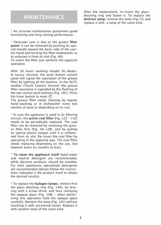
MAINTENANCEAfter the replacement, re-insert the glass-blocking ring and fasten it. To replace the dichroic lamp, remove the lamp (Fig.15) and replace it with a lamp of the same kind.
* An accurate maintenance guarantees good functioning and long-lasting performance.
* Particular care is due to the grease filter panel. It can be removed by pushing its spe-cial handle toward the back-side of the coo-ker hood and turning the filter downwards so to unfasten it from its slot (Fig. 4A). To insert the filter just perform the opposite operation.
After 30 hours working (model SIL-Modu-le luxury version), the push button control panel will signal the saturation of the grease filter by lighting all the buttons. In the SILTC models (Touch Control Version) the grease filter saturation is signalled by the flashing of the two central push buttons (Fig. 16C). Press the timer button to reset .The grease filter needs cleaning by regular hand-washing or in dishwasher every two months at least or depending on its use.
* In case the appliance is used in its filtering version, the active coal filter (Fig. 12Z - 13Z) needs to be periodically replaced. The coal filter can be removed by removing the grea-se filter first (Fig. 4A-12B), and by pulling its special plastic tongue until it is unfaste-ned from its slot. Re-insert the coal filter by operating in the opposite way. The coal filter needs replacing depending on the use, but however every six months at least.
* To clean the appliance itself tepid water and neutral detergent are recommended, while abrasive products should be avoided. For steel appliances specialized detergents are recommended (please follow the instruc-tions indicated o the product itself to obtain the desired results).
* To replace the halogen lamps, remove first the glass-blocking ring (Fig. 14A), by leve-ring with a screw-driver and thus removing the opaque glass (Fig. 14B) - when perfor-ming this operation hold the opaque glass carefully. Remove the lamp (Fig. 14C) without touching it with uncovered hands. Replace it with another lamp of the same kind.

9

10
1 2
3 4

11
5
76
Fig. 6.2
Fig. 6.1
Fig. 5.3
Fig. 5.2
Fig. 5.1
Fig. 7.6
Fig. 7.5
Fig. 7.4
Fig. 7.3
Fig. 7.2
Fig. 7.1

12
10
12
13
1415
16

13

14

15

90046104019 - GM 08/12