Embed Size (px)
Citation preview
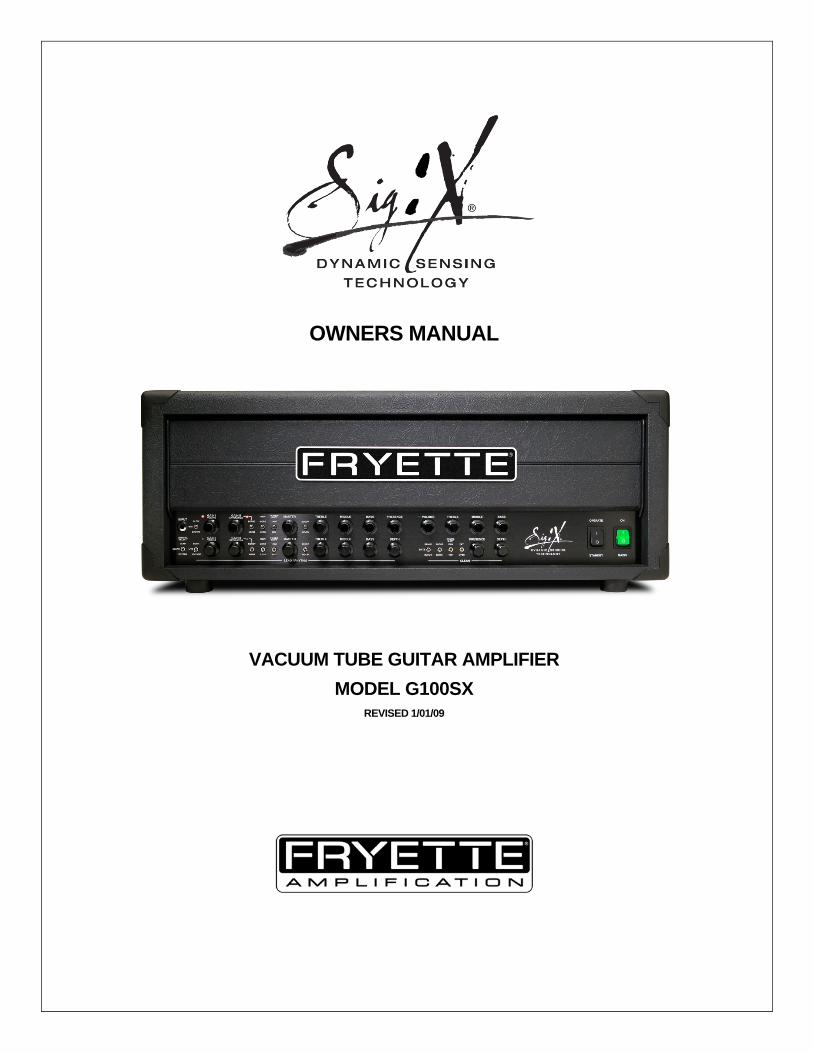
OWNERS MANUAL
VACUUM TUBE GUITAR AMPLIFIER MODEL G100SX
REVISED 1/01/09

X
Welcome to the family! Congratulations and thank you for choosing the FRYETTE SIG:X Guitar Amplifier!
We know you are constantly searching for new sounds and new ways to improve your existing sound. We understand the constantly evolving nature of artistic creativity and the search for the perfect sound to complement your ever-widening musical vision. Providing the tools to help you create your own sonic signature is our primary mission.
The SIG:X amplifier represents a new generation of tube amplifier design, offering players effortless and intuitive control over different types of amplifier behavior and a wide range of highly refined tonal qualities previously unavailable from a single amplifier. In 1980, design engineer Steven Fryette began developing advanced channel switching technology to allow guitarists the ability to make seamless transitions between channels and gain modes. In 1989 Steven introduced the first true three-channel tube amplifier – The Pittbull Classic. The SIG:X builds on this technology and establishes a new standard for channel switching amplifiers that blends vintage and modern character with outstanding tonal flexibility. As with all FRYETTE amplifiers, the SIG:X amplifier beautifully accentuates the inherent qualities of any instrument. It breathes and dynamically responds to your playing technique exactly the way a great guitar amp should. And as stomp boxes have gained more widespread appeal, you will find the SIG:X to be pedal friendly and ultra-responsive to the many colors pedal effects produce. Getting familiar with the SIG:X amplifier is easy, so don’t be terribly surprised when you find yourself up and running in no time. First hand experience and real world application will yield the ultimate satisfaction of finding your own path to comprehension and self-expression.
…YOUR SIGNATURE HERE
TABLE OF CONTENTS
1) INTRODUCTION 2) IMPORTANT SAFETY INSTRUCTIONS 3) FRONT PANEL OVERVIEW 4) A UNIQUE APPROACH TO TONE AND FEEL – THE LEAD CHANNEL 5) THE RHYTHM CHANNEL 6) THE CLEAN CHANNEL 7) UNDERSTANDING VOICING AND GAIN 8) SAMPLE SETTINGS – CLEAN CHANNEL SETTINGS 9) RHYTHM CHANNEL SETTINGS 10) LEAD CHANNEL SETTINGS 11) REAR PANEL FEATURES AND FUNCTIONS - SPEAKER OUTPUT CONNECTIONS
I. GROUND SWITCH, AC MAINS AND FUSES 12) EFFECTS LOOP CONNECTIONS 13) TUBE FUNCTION AND LOCATION CHART 14) TROUBLESHOOTING GUIDE
I. SPECIFICATIONS 15) WARRANTY
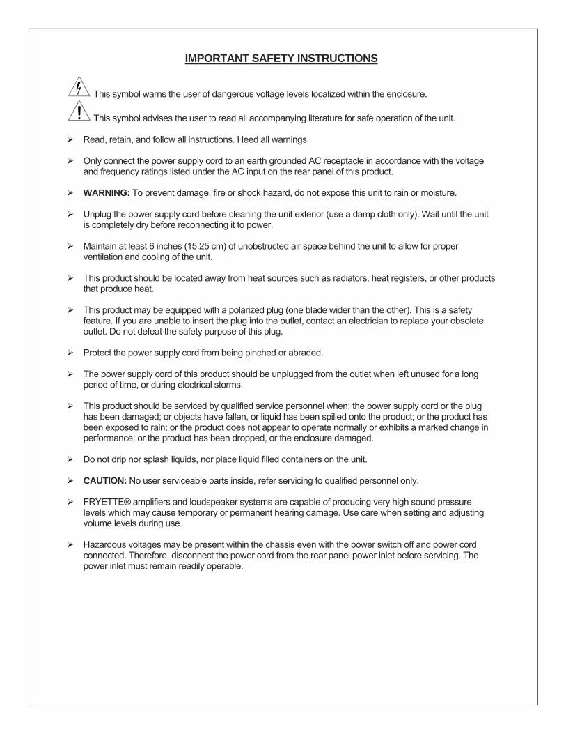
IMPORTANT SAFETY INSTRUCTIONS
This symbol warns the user of dangerous voltage levels localized within the enclosure.
This symbol advises the user to read all accompanying literature for safe operation of the unit.
Read, retain, and follow all instructions. Heed all warnings.
Only connect the power supply cord to an earth grounded AC receptacle in accordance with the voltage and frequency ratings listed under the AC input on the rear panel of this product.
WARNING: To prevent damage, fire or shock hazard, do not expose this unit to rain or moisture.
Unplug the power supply cord before cleaning the unit exterior (use a damp cloth only). Wait until the unit
is completely dry before reconnecting it to power.
Maintain at least 6 inches (15.25 cm) of unobstructed air space behind the unit to allow for proper ventilation and cooling of the unit.
This product should be located away from heat sources such as radiators, heat registers, or other products
that produce heat.
This product may be equipped with a polarized plug (one blade wider than the other). This is a safety feature. If you are unable to insert the plug into the outlet, contact an electrician to replace your obsolete outlet. Do not defeat the safety purpose of this plug.
Protect the power supply cord from being pinched or abraded.
The power supply cord of this product should be unplugged from the outlet when left unused for a long
period of time, or during electrical storms.
This product should be serviced by qualified service personnel when: the power supply cord or the plug has been damaged; or objects have fallen, or liquid has been spilled onto the product; or the product has been exposed to rain; or the product does not appear to operate normally or exhibits a marked change in performance; or the product has been dropped, or the enclosure damaged.
Do not drip nor splash liquids, nor place liquid filled containers on the unit.
CAUTION: No user serviceable parts inside, refer servicing to qualified personnel only.
FRYETTE® amplifiers and loudspeaker systems are capable of producing very high sound pressure
levels which may cause temporary or permanent hearing damage. Use care when setting and adjusting volume levels during use.
Hazardous voltages may be present within the chassis even with the power switch off and power cord
connected. Therefore, disconnect the power cord from the rear panel power inlet before servicing. The power inlet must remain readily operable.
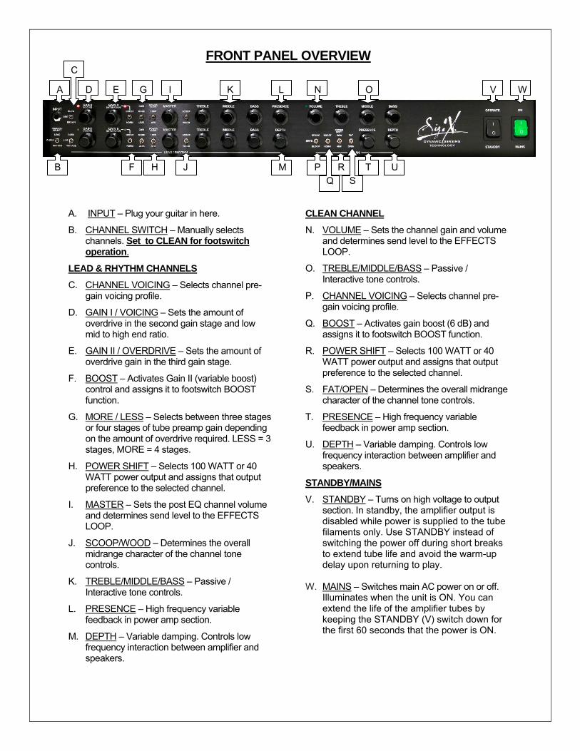
FRONT PANEL OVERVIEW
A. INPUT – Plug your guitar in here.
B. CHANNEL SWITCH – Manually selects channels. Set to CLEAN for footswitch operation.
LEAD & RHYTHM CHANNELS
C. CHANNEL VOICING – Selects channel pre-gain voicing profile.
D. GAIN I / VOICING – Sets the amount of overdrive in the second gain stage and low mid to high end ratio.
E. GAIN II / OVERDRIVE – Sets the amount of overdrive gain in the third gain stage.
F. BOOST – Activates Gain II (variable boost) control and assigns it to footswitch BOOST function.
G. MORE / LESS – Selects between three stages or four stages of tube preamp gain depending on the amount of overdrive required. LESS = 3 stages, MORE = 4 stages.
H. POWER SHIFT – Selects 100 WATT or 40 WATT power output and assigns that output preference to the selected channel.
I. MASTER – Sets the post EQ channel volume and determines send level to the EFFECTS LOOP.
J. SCOOP/WOOD – Determines the overall midrange character of the channel tone controls.
K. TREBLE/MIDDLE/BASS – Passive / Interactive tone controls.
L. PRESENCE – High frequency variable feedback in power amp section.
M. DEPTH – Variable damping. Controls low frequency interaction between amplifier and speakers.
CLEAN CHANNEL
N. VOLUME – Sets the channel gain and volume and determines send level to the EFFECTS LOOP.
O. TREBLE/MIDDLE/BASS – Passive / Interactive tone controls.
P. CHANNEL VOICING – Selects channel pre-gain voicing profile.
Q. BOOST – Activates gain boost (6 dB) and assigns it to footswitch BOOST function.
R. POWER SHIFT – Selects 100 WATT or 40 WATT power output and assigns that output preference to the selected channel.
S. FAT/OPEN – Determines the overall midrange character of the channel tone controls.
T. PRESENCE – High frequency variable feedback in power amp section.
U. DEPTH – Variable damping. Controls low frequency interaction between amplifier and speakers.
STANDBY/MAINS
V. STANDBY – Turns on high voltage to output section. In standby, the amplifier output is disabled while power is supplied to the tube filaments only. Use STANDBY instead of switching the power off during short breaks to extend tube life and avoid the warm-up delay upon returning to play.
W. MAINS – Switches main AC power on or off.
Illuminates when the unit is ON. You can extend the life of the amplifier tubes by keeping the STANDBY (V) switch down for the first 60 seconds that the power is ON.
A
B
D E
C
G
F H
I K L N O
T UP RQ S
V W
J M
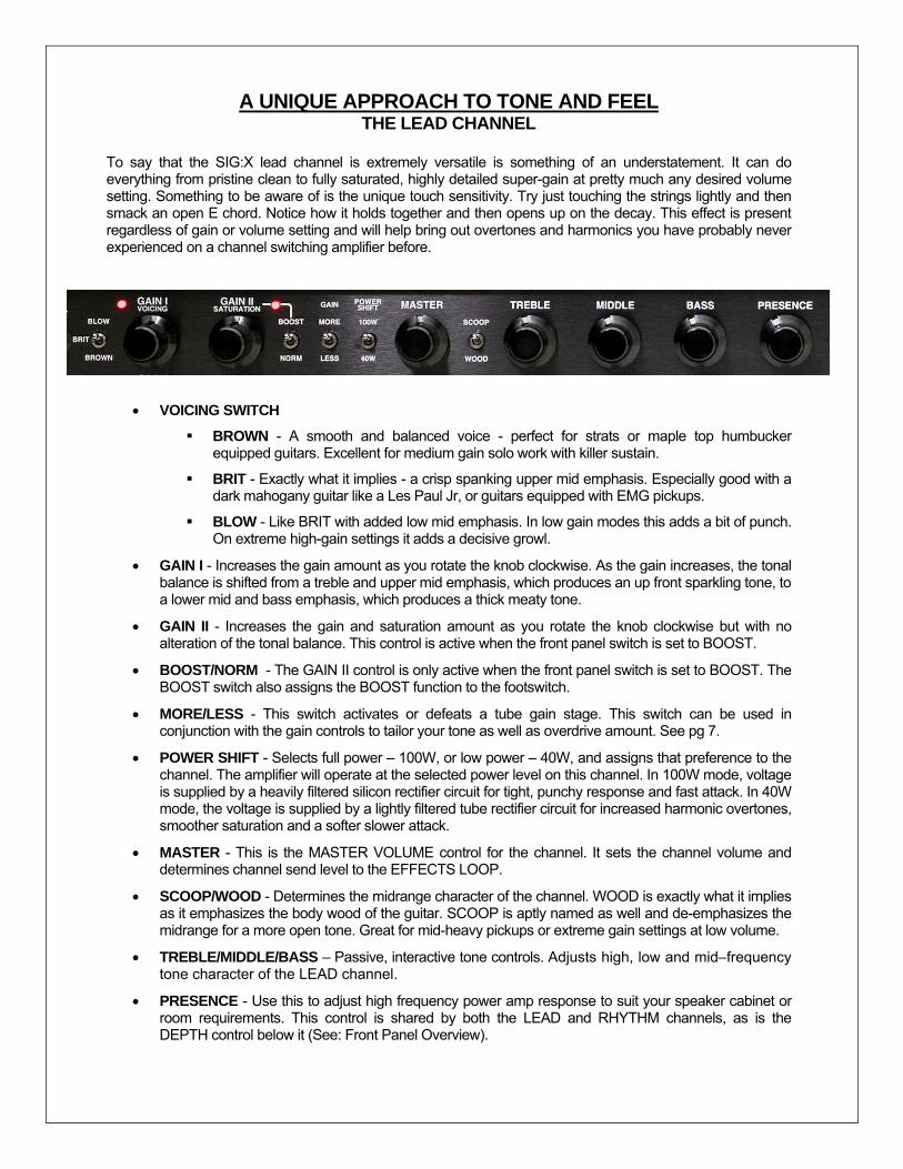
A UNIQUE APPROACH TO TONE AND FEEL THE LEAD CHANNEL
To say that the SIG:X lead channel is extremely versatile is something of an understatement. It can do everything from pristine clean to fully saturated, highly detailed super-gain at pretty much any desired volume setting. Something to be aware of is the unique touch sensitivity. Try just touching the strings lightly and then smack an open E chord. Notice how it holds together and then opens up on the decay. This effect is present regardless of gain or volume setting and will help bring out overtones and harmonics you have probably never experienced on a channel switching amplifier before.
• VOICING SWITCH
BROWN - A smooth and balanced voice - perfect for strats or maple top humbucker equipped guitars. Excellent for medium gain solo work with killer sustain.
BRIT - Exactly what it implies - a crisp spanking upper mid emphasis. Especially good with a dark mahogany guitar like a Les Paul Jr, or guitars equipped with EMG pickups.
BLOW - Like BRIT with added low mid emphasis. In low gain modes this adds a bit of punch. On extreme high-gain settings it adds a decisive growl.
• GAIN I - Increases the gain amount as you rotate the knob clockwise. As the gain increases, the tonal balance is shifted from a treble and upper mid emphasis, which produces an up front sparkling tone, to a lower mid and bass emphasis, which produces a thick meaty tone.
• GAIN II - Increases the gain and saturation amount as you rotate the knob clockwise but with no alteration of the tonal balance. This control is active when the front panel switch is set to BOOST.
• BOOST/NORM - The GAIN II control is only active when the front panel switch is set to BOOST. The BOOST switch also assigns the BOOST function to the footswitch.
• MORE/LESS - This switch activates or defeats a tube gain stage. This switch can be used in conjunction with the gain controls to tailor your tone as well as overdrive amount. See pg 7.
• POWER SHIFT - Selects full power – 100W, or low power – 40W, and assigns that preference to the channel. The amplifier will operate at the selected power level on this channel. In 100W mode, voltage is supplied by a heavily filtered silicon rectifier circuit for tight, punchy response and fast attack. In 40W mode, the voltage is supplied by a lightly filtered tube rectifier circuit for increased harmonic overtones, smoother saturation and a softer slower attack.
• MASTER - This is the MASTER VOLUME control for the channel. It sets the channel volume and determines channel send level to the EFFECTS LOOP.
• SCOOP/WOOD - Determines the midrange character of the channel. WOOD is exactly what it implies as it emphasizes the body wood of the guitar. SCOOP is aptly named as well and de-emphasizes the midrange for a more open tone. Great for mid-heavy pickups or extreme gain settings at low volume.
• TREBLE/MIDDLE/BASS – Passive, interactive tone controls. Adjusts high, low and mid–frequency tone character of the LEAD channel.
• PRESENCE - Use this to adjust high frequency power amp response to suit your speaker cabinet or room requirements. This control is shared by both the LEAD and RHYTHM channels, as is the DEPTH control below it (See: Front Panel Overview).

THE RHYTHM CHANNEL
This is probably the most versatile channel on the amplifier and produces what many consider to be the signature FRYETTE sound. Much more flexible than your average medium gain channel, it is capable of producing some brilliant cleans as well as pretty devastating solo settings. The RHYTHM channel differs from the LEAD channel only in VOICING switch nomenclature and internal tone shaping.
• VOICING SWITCH
VINTAGE - A round and warm voice - perfect for strats, teles or maple top humbucker equipped guitars. This is a great setting for low to medium gain action. In 40W mode you can achieve killer old-school EL34 sounds.
LIVE - Exactly what it implies - a lively feel added to the VINTAGE voice. This is a really cool setting when using RHYTHM for a slightly gritty clean sound. Also great for mid-gain blues work.
BURN - The LIVE voicing with added low mid emphasis. In low gain modes this adds a bit of 6L6 flavor. On high-gain settings it adds fundamental emphasis for killer rhythms and thick solos.
• GAIN I - Increases the gain amount as you rotate the knob clockwise. As the gain increases, the tonal balance is shifted from a treble and upper mid emphasis, which produces an up-front sparkling tone, to a lower mid and bass emphasis, which produces a thick meaty tone.
• GAIN II - Increases the gain and saturation amount as you rotate the knob clockwise but with no alteration of the tonal balance. This control is active when the front panel switch is set to BOOST.
• BOOST/NORM - The GAIN II control is only active when the front panel switch is set to BOOST. The BOOST switch also assigns the BOOST function to the footswitch.
• MORE/LESS - This switch activates or defeats a tube gain stage. This switch can be used in conjunction with the gain controls to tailor your tone as well as overdrive amount. See pg 7.
• POWER SHIFT - Selects full power – 100W, or low power – 40W, and assigns that preference to the channel. The amplifier will operate at the selected power level on this channel. In 100W mode, voltage is supplied by a heavily filtered silicon rectifier circuit for tight, punchy response and fast attack. In 40W mode, the voltage is supplied by a lightly filtered tube rectifier circuit for increased harmonic overtones, smoother saturation and a softer slower attack.
• MASTER - This is the MASTER VOLUME control for the channel. It sets the channel volume and determines channel send level to the EFFECTS LOOP.
• SCOOP/WOOD - Determines the midrange character of the channel. WOOD is exactly what it implies as it emphasizes the body wood of the guitar. SCOOP is aptly named as well and de-emphasizes the midrange for a more open, scooped out tone.
• TREBLE/MIDDLE/BASS - Passive and interactive tone controls for fine-tuning the channel to taste.
• DEPTH - Use this to adjust power amp low frequency behavior and interaction with the speaker. This control is shared by both the LEAD and RHYTHM channels, as is the PRESENCE control above it (See: Front Panel Overview).
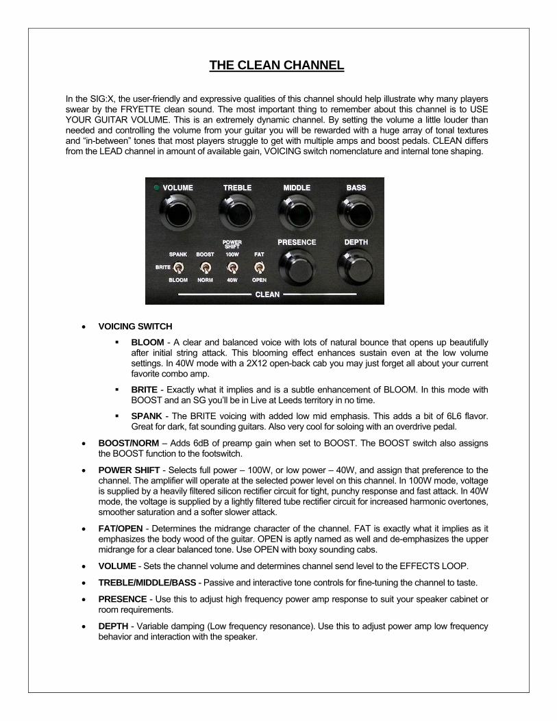
THE CLEAN CHANNEL
In the SIG:X, the user-friendly and expressive qualities of this channel should help illustrate why many players swear by the FRYETTE clean sound. The most important thing to remember about this channel is to USE YOUR GUITAR VOLUME. This is an extremely dynamic channel. By setting the volume a little louder than needed and controlling the volume from your guitar you will be rewarded with a huge array of tonal textures and “in-between” tones that most players struggle to get with multiple amps and boost pedals. CLEAN differs from the LEAD channel in amount of available gain, VOICING switch nomenclature and internal tone shaping.
• VOICING SWITCH
BLOOM - A clear and balanced voice with lots of natural bounce that opens up beautifully after initial string attack. This blooming effect enhances sustain even at the low volume settings. In 40W mode with a 2X12 open-back cab you may just forget all about your current favorite combo amp.
BRITE - Exactly what it implies and is a subtle enhancement of BLOOM. In this mode with BOOST and an SG you’ll be in Live at Leeds territory in no time.
SPANK - The BRITE voicing with added low mid emphasis. This adds a bit of 6L6 flavor. Great for dark, fat sounding guitars. Also very cool for soloing with an overdrive pedal.
• BOOST/NORM – Adds 6dB of preamp gain when set to BOOST. The BOOST switch also assigns the BOOST function to the footswitch.
• POWER SHIFT - Selects full power – 100W, or low power – 40W, and assign that preference to the channel. The amplifier will operate at the selected power level on this channel. In 100W mode, voltage is supplied by a heavily filtered silicon rectifier circuit for tight, punchy response and fast attack. In 40W mode, the voltage is supplied by a lightly filtered tube rectifier circuit for increased harmonic overtones, smoother saturation and a softer slower attack.
• FAT/OPEN - Determines the midrange character of the channel. FAT is exactly what it implies as it emphasizes the body wood of the guitar. OPEN is aptly named as well and de-emphasizes the upper midrange for a clear balanced tone. Use OPEN with boxy sounding cabs.
• VOLUME - Sets the channel volume and determines channel send level to the EFFECTS LOOP.
• TREBLE/MIDDLE/BASS - Passive and interactive tone controls for fine-tuning the channel to taste.
• PRESENCE - Use this to adjust high frequency power amp response to suit your speaker cabinet or room requirements.
• DEPTH - Variable damping (Low frequency resonance). Use this to adjust power amp low frequency behavior and interaction with the speaker.
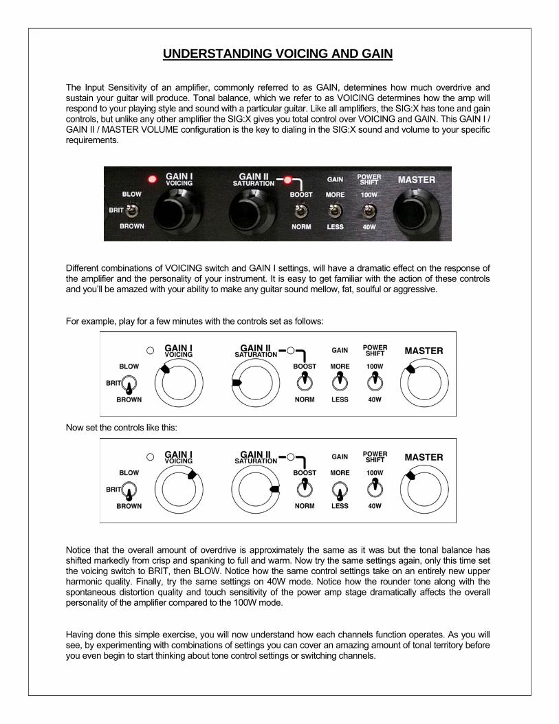
UNDERSTANDING VOICING AND GAIN
The Input Sensitivity of an amplifier, commonly referred to as GAIN, determines how much overdrive and sustain your guitar will produce. Tonal balance, which we refer to as VOICING determines how the amp will respond to your playing style and sound with a particular guitar. Like all amplifiers, the SIG:X has tone and gain controls, but unlike any other amplifier the SIG:X gives you total control over VOICING and GAIN. This GAIN I / GAIN II / MASTER VOLUME configuration is the key to dialing in the SIG:X sound and volume to your specific requirements.
Different combinations of VOICING switch and GAIN I settings, will have a dramatic effect on the response of the amplifier and the personality of your instrument. It is easy to get familiar with the action of these controls and you’ll be amazed with your ability to make any guitar sound mellow, fat, soulful or aggressive.
For example, play for a few minutes with the controls set as follows:
Now set the controls like this:
Notice that the overall amount of overdrive is approximately the same as it was but the tonal balance has shifted markedly from crisp and spanking to full and warm. Now try the same settings again, only this time set the voicing switch to BRIT, then BLOW. Notice how the same control settings take on an entirely new upper harmonic quality. Finally, try the same settings on 40W mode. Notice how the rounder tone along with the spontaneous distortion quality and touch sensitivity of the power amp stage dramatically affects the overall personality of the amplifier compared to the 100W mode.
Having done this simple exercise, you will now understand how each channels function operates. As you will see, by experimenting with combinations of settings you can cover an amazing amount of tonal territory before you even begin to start thinking about tone control settings or switching channels.
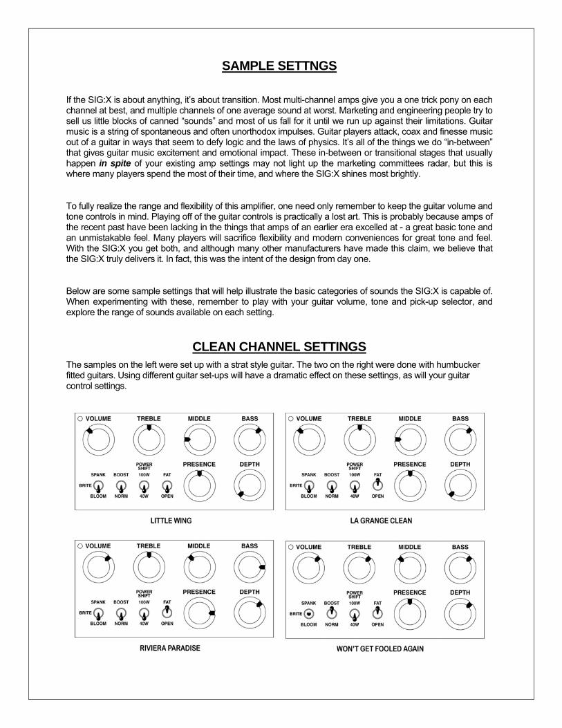
SAMPLE SETTNGS
If the SIG:X is about anything, it’s about transition. Most multi-channel amps give you a one trick pony on each channel at best, and multiple channels of one average sound at worst. Marketing and engineering people try to sell us little blocks of canned “sounds” and most of us fall for it until we run up against their limitations. Guitar music is a string of spontaneous and often unorthodox impulses. Guitar players attack, coax and finesse music out of a guitar in ways that seem to defy logic and the laws of physics. It’s all of the things we do “in-between” that gives guitar music excitement and emotional impact. These in-between or transitional stages that usually happen in spite of your existing amp settings may not light up the marketing committees radar, but this is where many players spend the most of their time, and where the SIG:X shines most brightly.
To fully realize the range and flexibility of this amplifier, one need only remember to keep the guitar volume and tone controls in mind. Playing off of the guitar controls is practically a lost art. This is probably because amps of the recent past have been lacking in the things that amps of an earlier era excelled at - a great basic tone and an unmistakable feel. Many players will sacrifice flexibility and modern conveniences for great tone and feel. With the SIG:X you get both, and although many other manufacturers have made this claim, we believe that the SIG:X truly delivers it. In fact, this was the intent of the design from day one.
Below are some sample settings that will help illustrate the basic categories of sounds the SIG:X is capable of. When experimenting with these, remember to play with your guitar volume, tone and pick-up selector, and explore the range of sounds available on each setting.
CLEAN CHANNEL SETTINGS The samples on the left were set up with a strat style guitar. The two on the right were done with humbucker fitted guitars. Using different guitar set-ups will have a dramatic effect on these settings, as will your guitar control settings.
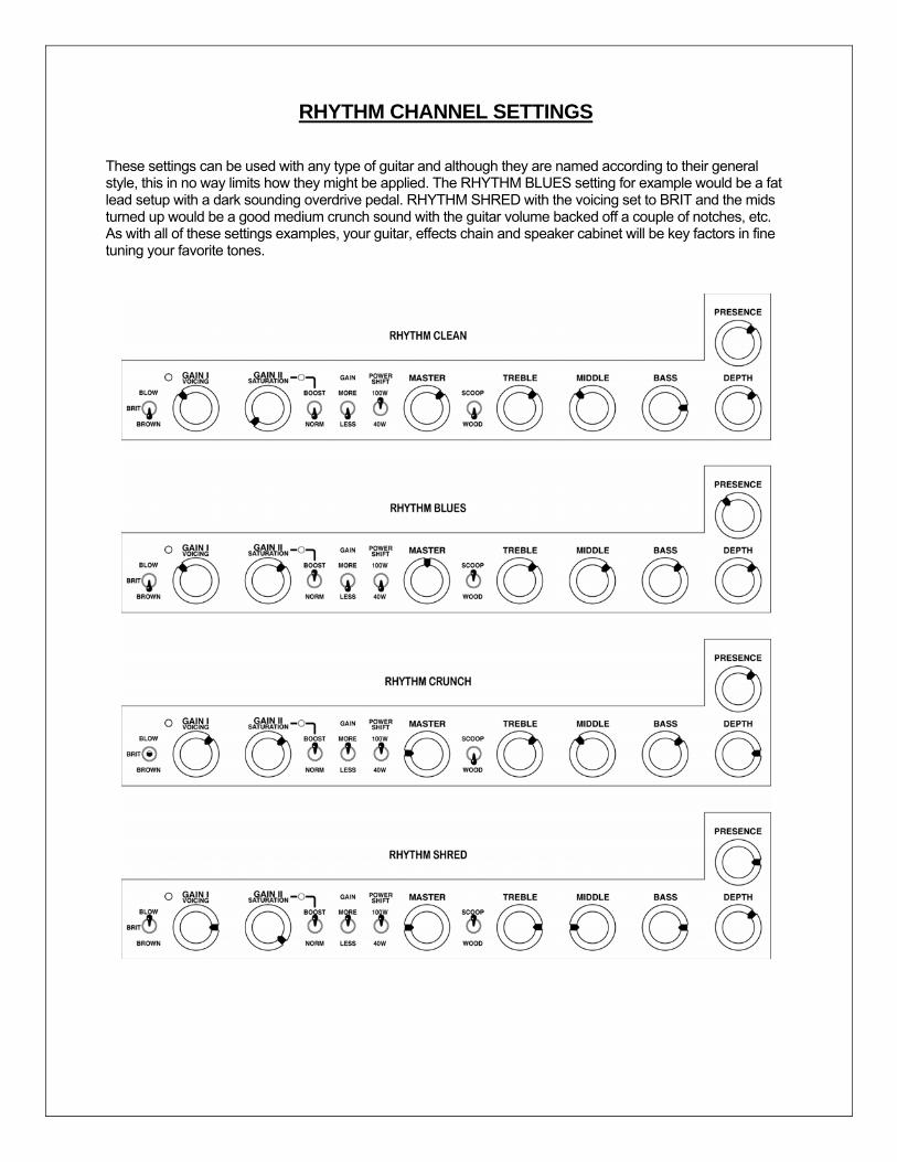
RHYTHM CHANNEL SETTINGS
These settings can be used with any type of guitar and although they are named according to their general style, this in no way limits how they might be applied. The RHYTHM BLUES setting for example would be a fat lead setup with a dark sounding overdrive pedal. RHYTHM SHRED with the voicing set to BRIT and the mids turned up would be a good medium crunch sound with the guitar volume backed off a couple of notches, etc. As with all of these settings examples, your guitar, effects chain and speaker cabinet will be key factors in fine tuning your favorite tones.
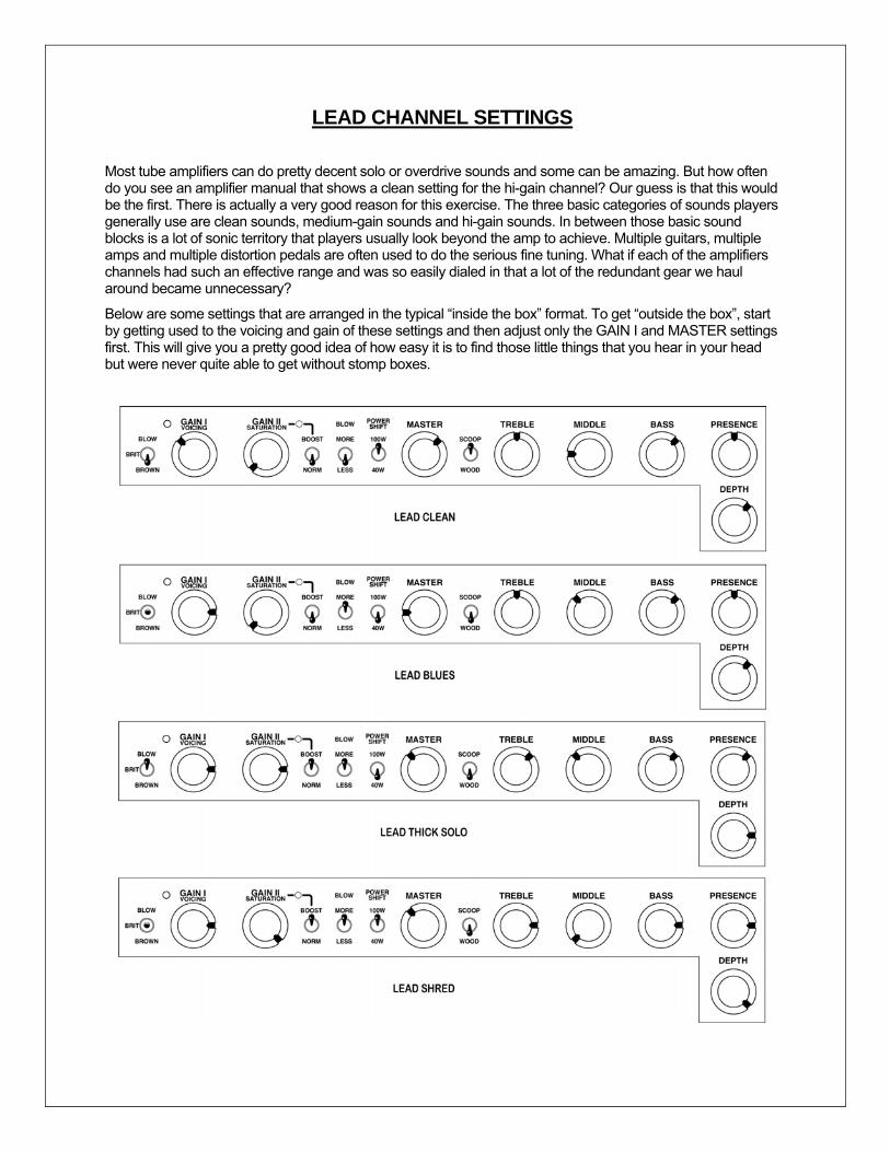
LEAD CHANNEL SETTINGS
Most tube amplifiers can do pretty decent solo or overdrive sounds and some can be amazing. But how often do you see an amplifier manual that shows a clean setting for the hi-gain channel? Our guess is that this would be the first. There is actually a very good reason for this exercise. The three basic categories of sounds players generally use are clean sounds, medium-gain sounds and hi-gain sounds. In between those basic sound blocks is a lot of sonic territory that players usually look beyond the amp to achieve. Multiple guitars, multiple amps and multiple distortion pedals are often used to do the serious fine tuning. What if each of the amplifiers channels had such an effective range and was so easily dialed in that a lot of the redundant gear we haul around became unnecessary?
Below are some settings that are arranged in the typical “inside the box” format. To get “outside the box”, start by getting used to the voicing and gain of these settings and then adjust only the GAIN I and MASTER settings first. This will give you a pretty good idea of how easy it is to find those little things that you hear in your head but were never quite able to get without stomp boxes.
REAR PANEL FEATURES AND FUNCTIONS
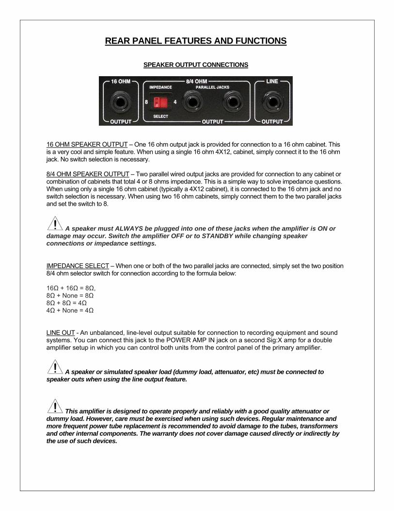
SPEAKER OUTPUT CONNECTIONS
16 OHM SPEAKER OUTPUT – One 16 ohm output jack is provided for connection to a 16 ohm cabinet. This is a very cool and simple feature. When using a single 16 ohm 4X12, cabinet, simply connect it to the 16 ohm jack. No switch selection is necessary. 8/4 OHM SPEAKER OUTPUT – Two parallel wired output jacks are provided for connection to any cabinet or combination of cabinets that total 4 or 8 ohms impedance. This is a simple way to solve impedance questions. When using only a single 16 ohm cabinet (typically a 4X12 cabinet), it is connected to the 16 ohm jack and no switch selection is necessary. When using two 16 ohm cabinets, simply connect them to the two parallel jacks and set the switch to 8.
A speaker must ALWAYS be plugged into one of these jacks when the amplifier is ON or damage may occur. Switch the amplifier OFF or to STANDBY while changing speaker connections or impedance settings.
IMPEDANCE SELECT – When one or both of the two parallel jacks are connected, simply set the two position 8/4 ohm selector switch for connection according to the formula below: 16Ω + 16Ω = 8Ω, 8Ω + None = 8Ω 8Ω + 8Ω = 4Ω 4Ω + None = 4Ω LINE OUT - An unbalanced, line-level output suitable for connection to recording equipment and sound systems. You can connect this jack to the POWER AMP IN jack on a second Sig:X amp for a double amplifier setup in which you can control both units from the control panel of the primary amplifier.
A speaker or simulated speaker load (dummy load, attenuator, etc) must be connected to speaker outs when using the line output feature.
This amplifier is designed to operate properly and reliably with a good quality attenuator or dummy load. However, care must be exercised when using such devices. Regular maintenance and more frequent power tube replacement is recommended to avoid damage to the tubes, transformers and other internal components. The warranty does not cover damage caused directly or indirectly by the use of such devices.
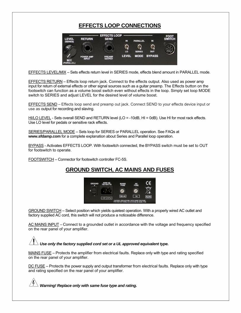
EFFECTS LOOP CONNECTIONS
EFFECTS LEVEL/MIX – Sets effects return level in SERIES mode, effects blend amount in PARALLEL mode.
EFFECTS RETURN – Effects loop return jack. Connect to the effects output. Also used as power amp input for return of external effects or other signal sources such as a guitar preamp. The Effects button on the footswitch can function as a volume boost switch even without effects in the loop. Simply set loop MODE switch to SERIES and adjust LEVEL for the desired level of volume boost. EFFECTS SEND – Effects loop send and preamp out jack. Connect SEND to your effects device input or use as output for recording and slaving. HI/LO LEVEL - Sets overall SEND and RETURN level (LO = -10dB, HI = 0dB). Use HI for most rack effects. Use LO level for pedals or sensitive rack effects.
SERIES/PARALLEL MODE – Sets loop for SERIES or PARALLEL operation. See FAQs at www.sfdamp.com for a complete explanation about Series and Parallel loop operation.
BYPASS - Activates EFFECTS LOOP. With footswitch connected, the BYPASS switch must be set to OUT for footswitch to operate.
FOOTSWITCH – Connector for footswitch controller FC-5S.
GROUND SWITCH, AC MAINS AND FUSES
GROUND SWITCH – Select position which yields quietest operation. With a properly wired AC outlet and factory supplied AC cord, this switch will not produce a noticeable difference.
AC MAINS INPUT – Connect to a grounded outlet in accordance with the voltage and frequency specified on the rear panel of your amplifier.
Use only the factory supplied cord set or a UL approved equivalent type. MAINS FUSE – Protects the amplifier from electrical faults. Replace only with type and rating specified on the rear panel of your amplifier. DC FUSE – Protects the power supply and output transformer from electrical faults. Replace only with type and rating specified on the rear panel of your amplifier.
Warning! Replace only with same fuse type and rating.
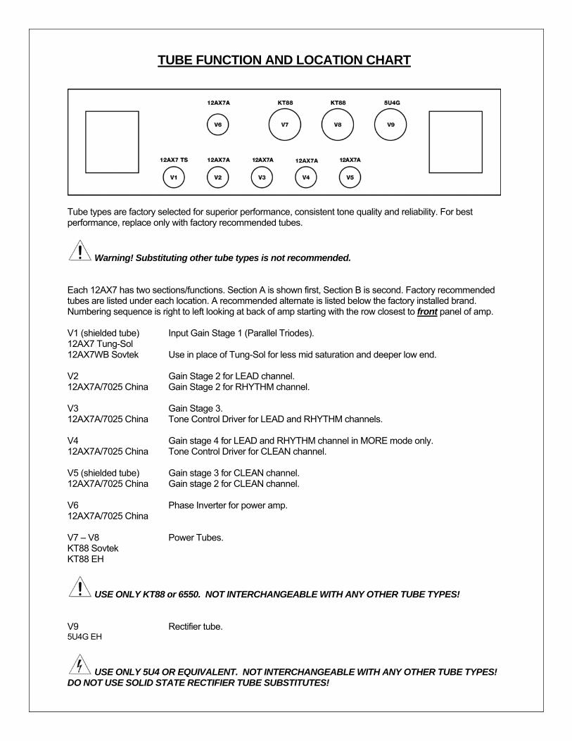
TUBE FUNCTION AND LOCATION CHART
Tube types are factory selected for superior performance, consistent tone quality and reliability. For best performance, replace only with factory recommended tubes.
Warning! Substituting other tube types is not recommended. Each 12AX7 has two sections/functions. Section A is shown first, Section B is second. Factory recommended tubes are listed under each location. A recommended alternate is listed below the factory installed brand. Numbering sequence is right to left looking at back of amp starting with the row closest to front panel of amp. V1 (shielded tube) Input Gain Stage 1 (Parallel Triodes). 12AX7 Tung-Sol 12AX7WB Sovtek Use in place of Tung-Sol for less mid saturation and deeper low end. V2 Gain Stage 2 for LEAD channel. 12AX7A/7025 China Gain Stage 2 for RHYTHM channel. V3 Gain Stage 3. 12AX7A/7025 China Tone Control Driver for LEAD and RHYTHM channels. V4 Gain stage 4 for LEAD and RHYTHM channel in MORE mode only. 12AX7A/7025 China Tone Control Driver for CLEAN channel. V5 (shielded tube) Gain stage 3 for CLEAN channel. 12AX7A/7025 China Gain stage 2 for CLEAN channel. V6 Phase Inverter for power amp. 12AX7A/7025 China V7 – V8 Power Tubes. KT88 Sovtek KT88 EH
USE ONLY KT88 or 6550. NOT INTERCHANGEABLE WITH ANY OTHER TUBE TYPES! V9 Rectifier tube. 5U4G EH
USE ONLY 5U4 OR EQUIVALENT. NOT INTERCHANGEABLE WITH ANY OTHER TUBE TYPES! DO NOT USE SOLID STATE RECTIFIER TUBE SUBSTITUTES!
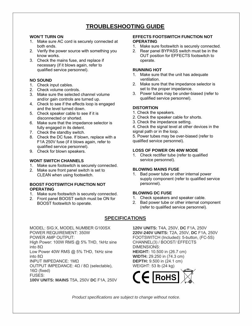
TROUBLESHOOTING GUIDE
WON’T TURN ON 1. Make sure AC cord is securely connected at
both ends. 2. Verify the power source with something you
know works. 3. Check the mains fuse, and replace if
necessary (if it blows again, refer to qualified service personnel).
NO SOUND 1. Check input cables. 2. Check volume controls. 3. Make sure the selected channel volume
and/or gain controls are turned up. 4. Check to see if the effects loop is engaged
and the level turned down. 5. Check speaker cable to see if it is
disconnected or shorted. 6. Make sure that the impedance selector is
fully engaged in its detent. 7. Check the standby switch. 8. Check the DC fuse. If blown, replace with a
F1A 250V fuse (if it blows again, refer to qualified service personnel).
9. Check for blown speakers. WONT SWITCH CHANNELS 1. Make sure footswitch is securely connected. 2. Make sure front panel switch is set to
CLEAN when using footswitch. BOOST FOOTSWITCH FUNCTION NOT OPERATING 1. Make sure footswitch is securely connected. 2. Front panel BOOST switch must be ON for
BOOST footswitch to operate.
EFFECTS FOOTSWITCH FUNCTION NOT OPERATING 1. Make sure footswitch is securely connected. 2. Rear panel BYPASS switch must be in the
OUT position for EFFECTS footswitch to operate.
RUNNING HOT 1. Make sure that the unit has adequate
ventilation. 2. Make sure that the impedance selector is
set to the proper impedance. 3. Power tubes may be under-biased (refer to
qualified service personnel).
DISTORTION 1. Check the speakers. 2. Check the speaker cable for shorts. 3. Check the impedance setting. 4. Check the signal level at other devices in the signal path or in the loop. 5. Power tubes may be over-biased (refer to qualified service personnel). LOSS OF POWER ON 40W MODE 1. Check rectifier tube (refer to qualified
service personnel). BLOWING MAINS FUSE 1. Bad power tube or other internal power
supply component (refer to qualified service personnel).
BLOWING DC FUSE 1. Check speakers and speaker cable. 2. Bad power tube or other internal component
(refer to qualified service personnel).
SPECIFICATIONS MODEL: SIG:X, MODEL NUMBER G100SX POWER REQUIREMENT: 350W POWER AMP OUTPUT: High Power: 100W RMS @ 5% THD, 1kHz sine into 8Ω Low Power 40W RMS @ 5% THD, 1kHz sine into 8Ω INPUT IMPEDANCE: 1MΩ OUTPUT IMPEDANCE: 4Ω / 8Ω (selectable), 16Ω (fixed) FUSES: 100V UNITS: MAINS T5A, 250V DC F1A, 250V
120V UNITS: T4A, 250V, DC F1A, 250V 220V-240V UNITS: T2A, 250V, DC F1A, 250V FOOTSWITCH (Included): 5-button, (FC-5S) CHANNEL(3) / BOOST/ EFFECTS DIMENSIONS: HEIGHT: 10.500 in (26.7 cm) WIDTH: 29.250 in (74.3 cm) DEPTH: 9.500 in (24.1 cm) WEIGHT: 53 lb (24 kg)
Product specifications are subject to change without notice.

Certificate of Compliance
Restriction of the use of Hazardous Substances (RoHS)
We certify that all of our products (exceptions see listed below) are compliant with the European Union Directive 2002/95/EC for the Restriction of the use of certain Hazardous Substances in Electrical and Electronic Equipment (RoHS). No Lead (Pb), Cadmium (Cd), Mercury (Hg), Hexavalent Chromium (Cr+6), PBB or PBDE is intentionally added to these devices. Any trace impurities of these substances contained in the parts are below the RoHS specified threshold levels. All information provided in this Certificate of Compliance is accurate to the best of our knowledge as of the date this Certification was issued.
Certificate of Compliance Registration, Evaluation, Authorization and Restriction of chemicals (REACh)
We declare that all of our products are compliant with European Union Directive EC1907/206 for the Registration, Evaluation, Authorization and Restriction of chemicals (REACh), and contain none or less than 0.1% of the chemicals listed as hazardous chemicals in the REACh regulation. All information provided in this Certificate of Compliance is accurate to the best of our knowledge as of the date this Certification was issued.
Declaration of Conformity EMC and Low Voltage Directive (CE)
Product Name: SIG:X Amplifier Model Number: G-100-SX This is to certify that the product listed above complies with the following European Union Council Directives and Standards relating to electromagnetic compatibility (EMC Directive 89/336/EEC) and the low voltage Directive (73/23/EEC). This declaration of conformity of the European Communities is the result of an examination carried out by Electromagnetic Engineering Services, Inc. in accordance with European Standards EN 50081-1, EN 50082-1 and EN 60065 for low voltage, as laid down in Article 10 of the EMC Directive. Steven Fryette Design, Inc 1201 South Flower Street Burbank, CA 91502 USA
1201 South Flower StreetBURBANK, CA 91502
LIMITED WARRANTY
Subject to the obligations and exclusions found below, this product is warranted by Steven Fryette Design, Inc., (herein SFD) against manufacturing defects in materials and workmanship for the period of Five (5) Years from the date of purchase, with the exception of the tubes, fuses and speakers where applicable, which carry a 90 day warranty.
The warranty period commences on the date of purchase by the original user. Performance under this warranty must be obtained at one of the following: an SFD Authorized Service Station, by returning the unit to the SFD factory with prior written authorization, or (in countries outside of the United States) by a representative SFD distributor.
Obligations
1. This warranty will be honored only on the presentation of the original proof of purchase. 2. Transportation of the product to and from an authorized SFD service outlet is the responsibility of the user. Units sent directly to
the SFD factory for warranty repairs must be authorized by SFD and shipped prepaid.
Exclusions
1. This warranty shall not cover adjustment of consumer-operated controls as explained in the appropriate instruction manual, or products that have been altered or have missing, or defaced serial numbers.
2. This warranty shall not apply to the appearance of accessory items including but not limited to, cabinets, cabinet parts, or knobs. 3. This warranty does not apply to uncrating, setup, installation, or the removal and reinstallation of products for repair. 4. This warranty shall not apply to repair or replacements necessitated by any cause beyond the control of SFD including, but not
limited to, any malfunction, defects, or failure caused by or resulting from unauthorized service or parts, damaged or broken tubes, incorrect line voltage, improper maintenance, modification or repair by the user, abuse misuse, neglect, accident, fire, flood, or other Acts of God.
5. Responsibility for the repair of any SFD product sold outside of U.S. boundaries is borne by the SFD representative in that particular country or territory. Also, the warranty term and conditions may be different from those stated above. Please contact the SFD distributor or dealer in your country for more information.
The foregoing is in lieu of all other expressed warranties, and SFD does not authorize any party to assume for it any other obligation or liability. In no event shall SFD be liable for special or consequential damages arising from the use of this product, or for any delay in the performance of this warranty due to causes beyond our control. Some states do not allow limitations on how long an implied warranty lasts and/or do not allow the exclusion or limitation of consequential damages, so the above limitations on implied warranty and consequential damages may not apply to you. This warranty gives you specific legal rights. You may have other rights that vary from state to state.
WARRANTY REGISTRATION
U.S. and Canadian residents may register their Fryette product(s) online at www.sfdamp.com/support_form.aspx by selecting and completing the Warranty Registration form. All other international residents please contact the authorized distributor your Fryette product was purchased from. For a list of international distributors please visit www.sfdamp.com/dealers.html
STEVEN FRYETTE DESIGN, INC.
1201 S. FLOWER STREET BURBANK, CA 91502
TEL (818) 846-4000 FAX (818) 846-4040 www.sfdamp.com
Copyright 2009 Steven Fryette Design, Inc.