Embed Size (px)
Citation preview
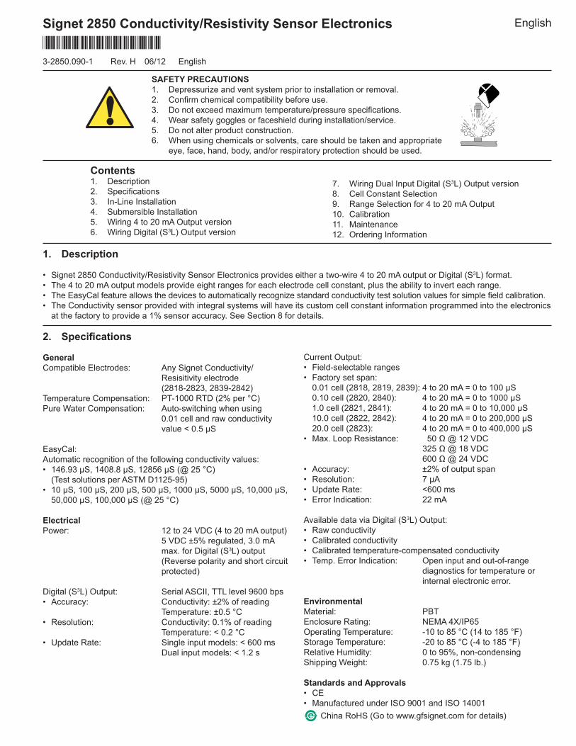
Signet 2850 Conductivity/Resistivity Sensor Electronics English
1. Description
• Signet 2850 Conductivity/Resistivity Sensor Electronics provides either a two-wire 4 to 20 mA output or Digital (S3L) format.• The 4 to 20 mA output models provide eight ranges for each electrode cell constant, plus the ability to invert each range.• The EasyCal feature allows the devices to automatically recognize standard conductivity test solution values for simple fi eld calibration.• The Conductivity sensor provided with integral systems will have its custom cell constant information programmed into the electronics
at the factory to provide a 1% sensor accuracy. See Section 8 for details.
SAFETY PRECAUTIONS1. Depressurize and vent system prior to installation or removal.2. Confi rm chemical compatibility before use.3. Do not exceed maximum temperature/pressure specifi cations.4. Wear safety goggles or faceshield during installation/service.5. Do not alter product construction.6. When using chemicals or solvents, care should be taken and appropriate
eye, face, hand, body, and/or respiratory protection should be used.
2. Specifi cations
GeneralCompatible Electrodes: Any Signet Conductivity/
Resisitivity electrode (2818-2823, 2839-2842)Temperature Compensation: PT-1000 RTD (2% per °C)Pure Water Compensation: Auto-switching when using
0.01 cell and raw conductivity value < 0.5 μS
EasyCal:Automatic recognition of the following conductivity values:• 146.93 μS, 1408.8 μS, 12856 μS (@ 25 °C) (Test solutions per ASTM D1125-95)• 10 μS, 100 μS, 200 μS, 500 μS, 1000 μS, 5000 μS, 10,000 μS,
50,000 μS, 100,000 μS (@ 25 °C)
ElectricalPower: 12 to 24 VDC (4 to 20 mA output) 5 VDC ±5% regulated, 3.0 mA
max. for Digital (S3L) output (Reverse polarity and short circuit protected)
Digital (S3L) Output: Serial ASCII, TTL level 9600 bps• Accuracy: Conductivity: ±2% of reading Temperature: ±0.5 °C• Resolution: Conductivity: 0.1% of reading Temperature: < 0.2 °C• Update Rate: Single input models: < 600 ms Dual input models: < 1.2 s
Current Output:• Field-selectable ranges• Factory set span: 0.01 cell (2818, 2819, 2839): 4 to 20 mA = 0 to 100 μS 0.10 cell (2820, 2840): 4 to 20 mA = 0 to 1000 μS 1.0 cell (2821, 2841): 4 to 20 mA = 0 to 10,000 μS 10.0 cell (2822, 2842): 4 to 20 mA = 0 to 200,000 μS 20.0 cell (2823): 4 to 20 mA = 0 to 400,000 μS• Max. Loop Resistance: 50 Ω @ 12 VDC 325 Ω @ 18 VDC 600 Ω @ 24 VDC• Accuracy: ±2% of output span• Resolution: 7 μA• Update Rate: <600 ms• Error Indication: 22 mA
Available data via Digital (S3L) Output:• Raw conductivity• Calibrated conductivity• Calibrated temperature-compensated conductivity• Temp. Error Indication: Open input and out-of-range
diagnostics for temperature or internal electronic error.
EnvironmentalMaterial: PBTEnclosure Rating: NEMA 4X/IP65Operating Temperature: -10 to 85 °C (14 to 185 °F)Storage Temperature: -20 to 85 °C (-4 to 185 °F)Relative Humidity: 0 to 95%, non-condensingShipping Weight: 0.75 kg (1.75 lb.)
Standards and Approvals• CE• Manufactured under ISO 9001 and ISO 14001
3-2850.090-1 Rev. H 06/12 English
*3-2850.090-1*
Contents1. Description2. Specifi cations3. In-Line Installation4. Submersible Installation5. Wiring 4 to 20 mA Output version6. Wiring Digital (S3L) Output version
7. Wiring Dual Input Digital (S3L) Output version8. Cell Constant Selection9. Range Selection for 4 to 20 mA Output10. Calibration11. Maintenance12. Ordering Information
China RoHS (Go to www.gfsignet.com for details)
2 2850 Conductivity/Resistivity Sensor Electronics
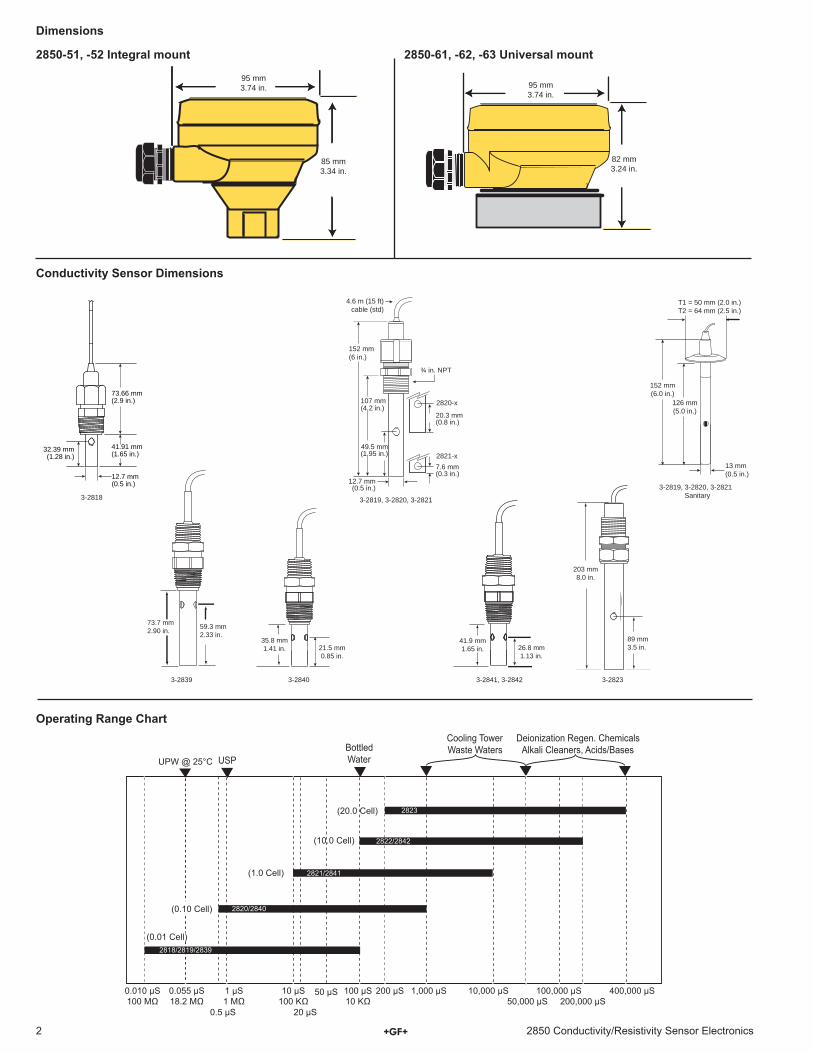
Dimensions
2850-51, -52 Integral mount 2850-61, -62, -63 Universal mount
Operating Range Chart
Conductivity Sensor Dimensions
1 μS 10 μS 1,000 μS 10,000 μS 50,000 μS
50 μS
0.5 μS 20 μS 200,000 μS
100 μS 400,000 μS 200 μS 100,000 μS 0.055 μS 0.010 μS
2818/2819/2839
2820/2840
2821/2841
2822/2842
2823
Bottled Water UPW @ 25°C USP
Cooling Tower Waste Waters
Deionization Regen. Chemicals Alkali Cleaners, Acids/Bases
(0.01 Cell)
(0.10 Cell)
(1.0 Cell)
(10.0 Cell)
(20.0 Cell)
85 mm3.34 in.
82 mm3.24 in.
95 mm3.74 in. 95 mm
3.74 in.
3-28233-2841, 3-2842
26.8 mm1.13 in.
41.9 mm1.65 in.
203 mm8.0 in.
89 mm3.5 in.
3-2839 3-2840
59.3 mm2.33 in.
73.7 mm2.90 in.
21.5 mm0.85 in.
35.8 mm1.41 in.
3-2819, 3-2820, 3-2821Sanitary
13 mm(0.5 in.)
152 mm(6.0 in.)
126 mm(5.0 in.)
T1 = 50 mm (2.0 in.)T2 = 64 mm (2.5 in.)
3-2819, 3-2820, 3-2821
2821-x
2820-x
152 mm(6 in.)
107 mm(4.2 in.)
¾ in. NPT
4.6 m (15 ft)cable (std)
12.7 mm(0.5 in.)
20.3 mm(0.8 in.)
7.6 mm(0.3 in.)
49.5 mm(1.95 in.)
3-2818
32.39 mm(1.28 in.)
12.7 mm(0.5 in.)
73.66 mm(2.9 in.)
41.91 mm(1.65 in.)
32850 Conductivity/Resistivity Sensor Electronics
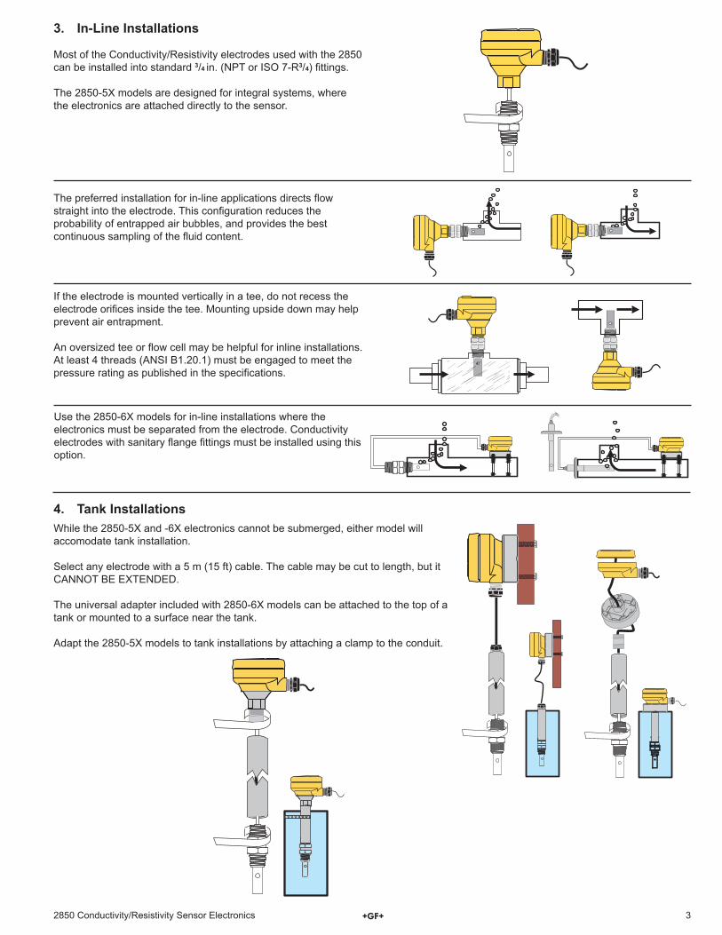
3. In-Line Installations
Most of the Conductivity/Resistivity electrodes used with the 2850 can be installed into standard 3/4 in. (NPT or ISO 7-R3/4) fi ttings.
The 2850-5X models are designed for integral systems, where the electronics are attached directly to the sensor.
The preferred installation for in-line applications directs fl ow straight into the electrode. This confi guration reduces the probability of entrapped air bubbles, and provides the best continuous sampling of the fl uid content.
Use the 2850-6X models for in-line installations where the electronics must be separated from the electrode. Conductivity electrodes with sanitary fl ange fi ttings must be installed using this option.
4. Tank InstallationsWhile the 2850-5X and -6X electronics cannot be submerged, either model will accomodate tank installation.
Select any electrode with a 5 m (15 ft) cable. The cable may be cut to length, but it CANNOT BE EXTENDED.
The universal adapter included with 2850-6X models can be attached to the top of a tank or mounted to a surface near the tank.
Adapt the 2850-5X models to tank installations by attaching a clamp to the conduit.
If the electrode is mounted vertically in a tee, do not recess the electrode orifi ces inside the tee. Mounting upside down may help prevent air entrapment.
An oversized tee or fl ow cell may be helpful for inline installations.At least 4 threads (ANSI B1.20.1) must be engaged to meet the pressure rating as published in the specifi cations.
4 2850 Conductivity/Resistivity Sensor Electronics
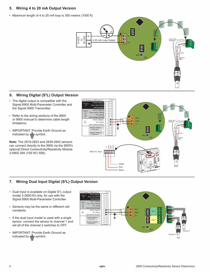
5. Wiring 4 to 20 mA Output Version
6. Wiring Digital (S3L) Output Version
7. Wiring Dual Input Digital (S3L) Output Version
• Dual input is available on Digital S3L output model 3-2850-63 only, for use with the Signet 8900 Multi-Parameter Controller.
• Sensors may be the same or different cell constants.
• If the dual input model is used with a single sensor, connect the sensor to channel 1 and set all of the channel 2 switches to OFF.
• IMPORTANT: Provide Earth Ground as indicated by symbol.
• The digital output is compatible with the Signet 8900 Multi-Parameter Controller and the Signet 9900 Transmitter.
• Refer to the wiring sections of the 8900 or 9900 manual to determine cable length limitations.
• IMPORTANT: Provide Earth Ground as indicated by symbol.
• Maximum length of 4 to 20 mA loop is 300 meters (1000 ft)
SW1 D3
1
2
3
1 2
3 4
ON
C
TS
1 2
3 4
ON
C
TS
4 20
V-
V+
Temp. IN (WHITE)
Sensr Gnd (SHIELD)
Signal IN (RED)
Signal RTN (BLK)
9 V
DC
to
26 V
DC
4-20 mA Loop Output
SW1 D3
1
2
3
1 2
3 4
ON
C
TS
3-8900.621C I/O Module 3-8900.401-X 1
2
3
4
5
6
7
8
9
10
11
12
13
14
+5VDC (Black) Freq. Input (Red)
GND (Shield) +5VDC (Black)
Freq. Input 2 (Red) S L (Red)
GND (White/Shield) +5VDC (Black)
S L (Red) GND (White/Shield)
3
3
Analog Output 1
Analog Output 2
(if applicable)
(if applicable)
Frequency Input
1
Frequency Input 2
OR S3L Input
2
S3L Input
1
+ -
+ -
V+
DATA
GN
DS
HLD
V+
DC Power
Loop Voltage
3-9900.395
H COMM Module
Gnd
Data
Temp. IN(WHITE)
Sensr Gnd(SHIELD)
Signal IN(RED)
Signal RTN(BLK)
BlackRedWhite
9900 S3L Input
SW1 D3
1
2
3
1 2
3 4
ON
C
TS
1 2
3 4
ON
C
TS
V+
3-8900.621C I/O Module 3-8900.401-X 1
2
3
4
5
6
7
8
9
10
11
12
13
14
+5VDC (Black) Freq. Input (Red)
GND (Shield) +5VDC (Black)
Freq. Input 2 (Red) S L (Red)
GND (White/Shield) +5VDC (Black)
S L (Red) GND (White/Shield)
3
3
Analog Output 1
Analog Output 2
(if applicable)
(if applicable)
Frequency Input
1
Frequency Input 2
OR S3L Input
2
S3L Input
1
+ -
+ -
Gnd
Data
Ch 1
Ch 2
Sensor 1
Sensor 2
Note: The 2819-2823 and 2839-2842 sensors can connect directly to the 9900 via the 9900's optional Direct Conductivity/Resistivity Module 3-9900.394 (159 001 699).
52850 Conductivity/Resistivity Sensor Electronics
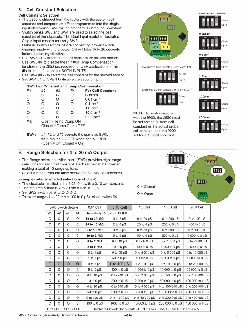
• The Range selection switch bank (SW2) provides eight range selections for each cell constant. Each range can be inverted, making a total of 16 range options.
• Select a range from the table below and set SW2 as indicated.
O = Open
C = Closed
Example (refer to shaded selections of chart):• The electrode installed is the 3-2840-1, with a 0.10 cell constant.• The required output is 4 to 20 mA = 0 to 100 μS.• Set SW2 switch bank to C-C-O-O.• To invert range (4 to 20 mA = 100 to 0 μS), close switch #4.
1 2 3 4
ON CTS
1 2 3
SW
1
SW3 SW4
D3
1 2 3 4
ON CTS
1 2 3 4
ON CTS
1 2 3 4
ON CTS
1 2 3 4
ON CTS
1 2 3 4
ON CTS1 2 3 4
ON CTS
1 2 3 4
ON CTS
1 2 3 4
ON CTS
1 2 3 4
ON CTS
Ch 1 Ch 2
1 2 3 4
ON CTS
0.01/cm-1
0.1/cm-1
1.0/cm-1
10.0/cm-1
20.0/cm-1
Open
Closed
Open
Closed
Closed
Open
Closed
Open
Closed
Open
Closed
Open
Closed
Open
Example: 1.0 cell constant, temp comp ON
Example: 1.0 cell constant, temp comp OFF
Closed
Open
Custom Cell Constant8. Cell Constant SelectionCell Constant Selection• The 2850 is shipped from the factory with the custom cell
constant and temperature offset programmed into the single-input electronics. SW3 will be preset to "Custom cell constant".
• Switch banks SW3 and SW4 are used to select the cell constant of the electrode. The Dual Input model is illustrated. Single input models use only SW3.
• Make all switch settings before connecting power. Switch changes made with the power ON will take 15 to 20 seconds before becoming effective.
• Use SW3 #1-3 to select the cell constant for the fi rst sensor.• Use SW3 #4 to disable the PT1000 Temp Compensation
function in the 2850 (as required for USP applications.) This disables the function for BOTH INPUTS.
• Use SW4 #1-3 to select the cell constant for the second sensor.• Set SW4 #4 to OPEN to disable the second input.
SW
1
SW2
SW2
SW
3 D3
1 2 3 4
ON CTS
1 2 3 4
ON CTS
1 3 2
1 2 3 4
ON CTS
SW3 Cell Constant and Temp Compensation#1 #2 #3 #4 For Cell ConstantC C C O CustomC O O O 0.01 cm-1
O C O O 0.1 cm-1
C C O O 1.0 cm-1
O O C O 10.0 cm-1
C O C O 20.0 cm-1
#4: Open = Temp Comp ON Closed = Temp Comp OFF
SW4: #1, #2 and #3 operate the same as SW3. #4 turns input 2 OFF when set to OPEN. (Open = Off, Closed = On)
9. Range Selection for 4 to 20 mA Output
SW2 Switch Setting 0.01 Cell 0.10 Cell 1.0 Cell 10.0 Cell 20.0 Cell
#1 #2 #3 #4 Resistivity Ranges in BOLDC C C O 10 to 20 MΩ 0 to 2 μS 0 to 20 μS 0 to 200 μS 0 to 400 μS
C C C C 20 to 10 MΩ 2 to 0 μS 20 to 0 μS 200 to 0 μS 400 to 0 μS
O C C O 2 to 10 MΩ 0 to 5 μS 0 to 50 μS 0 to 500 μS 0 to 1000 μS
O C C C 10 to 2 MΩ 5 to 0 μS 50 to 0 μS 500 to 0 μS 1 000 to 0 μS
C O C O 0 to 2 MΩ 0 to 10 μS 0 to 100 μS 0 to 1 000 μS 0 to 2 000 μS
C O C C 2 to 0 MΩ 10 to 0 μS 100 to 0 μS 1 000 to 0 μS 2 000 to 0 μS
O O C O 0 to 1 μS 0 to 50 μS 0 to 5 000 μS 0 to 5 000 μS 0 to 10 000 μS
O O C C 1 to 0 μS 50 to 0 μS 500 to 0 μS 5 000 to 0 μS 10 000 to 0 μS
C C O O 0 to 5 μS 0 to 100 μS 0 to 1 000 μS 0 to 10 000 μS 0 to 20 000 μS
C C O C 5 to 0 μS 100 to 0 μS 1 000 to 0 μS 10 000 to 0 μS 20 000 to 0 μS
O C O O 0 to 10 μS 0 to 200 μS 0 to 2 000 μS 0 to 50 000 μS 0 to 100 000 μS
O C O C 10 to 0 μS 200 to 0 μS 2 000 to 0 μS 50 000 to 0 μS 100 000 to 0 μS
C O O O 0 to 50 μS 0 to 500 μS 0 to 5 000 μS 0 to 100 000 μS 0 to 200 000 μS
C O O C 50 to 0 μS 500 to 0 μS 5 000 to 0 μS 100 000 to 0 μS 200 000 to 0 μS
O O O O 0 to 100 μS 0 to 1 000 μS 0 to 10 000 μS 0 to 200 000 μS 0 to 400 000 μS
O O O C 100 to 0 μS 1000 to 0 μS 10 000 to 0 μS 200 000 to 0 μS 400 000 to 0 μS
C = CLOSED O = OPEN Switch #4 inverts the output: OPEN = 4 to 20 mA, CLOSED = 20 to 4 mA
NOTE: To work correctly with the 9900, the 2850 must be set for the custom cell constant or the actual probe cell constant and the 9900 set for a 1.0 cell constant.
6 2850 Conductivity/Resistivity Sensor Electronics
10. Calibration
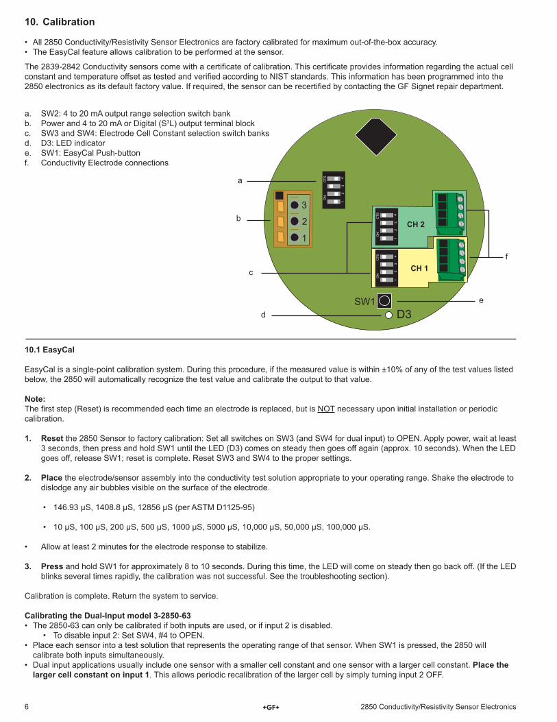
• All 2850 Conductivity/Resistivity Sensor Electronics are factory calibrated for maximum out-of-the-box accuracy.• The EasyCal feature allows calibration to be performed at the sensor.
10.1 EasyCal
EasyCal is a single-point calibration system. During this procedure, if the measured value is within ±10% of any of the test values listed below, the 2850 will automatically recognize the test value and calibrate the output to that value.
Note:The fi rst step (Reset) is recommended each time an electrode is replaced, but is NOT necessary upon initial installation or periodic calibration.
1. Reset the 2850 Sensor to factory calibration: Set all switches on SW3 (and SW4 for dual input) to OPEN. Apply power, wait at least 3 seconds, then press and hold SW1 until the LED (D3) comes on steady then goes off again (approx. 10 seconds). When the LED goes off, release SW1; reset is complete. Reset SW3 and SW4 to the proper settings.
2. Place the electrode/sensor assembly into the conductivity test solution appropriate to your operating range. Shake the electrode to dislodge any air bubbles visible on the surface of the electrode.
• 146.93 μS, 1408.8 μS, 12856 μS (per ASTM D1125-95)
• 10 μS, 100 μS, 200 μS, 500 μS, 1000 μS, 5000 μS, 10,000 μS, 50,000 μS, 100,000 μS.
• Allow at least 2 minutes for the electrode response to stabilize.
3. Press and hold SW1 for approximately 8 to 10 seconds. During this time, the LED will come on steady then go back off. (If the LED blinks several times rapidly, the calibration was not successful. See the troubleshooting section).
Calibration is complete. Return the system to service.
Calibrating the Dual-Input model 3-2850-63• The 2850-63 can only be calibrated if both inputs are used, or if input 2 is disabled.
• To disable input 2: Set SW4, #4 to OPEN.• Place each sensor into a test solution that represents the operating range of that sensor. When SW1 is pressed, the 2850 will
calibrate both inputs simultaneously.• Dual input applications usually include one sensor with a smaller cell constant and one sensor with a larger cell constant. Place the
larger cell constant on input 1. This allows periodic recalibration of the larger cell by simply turning input 2 OFF.
a. SW2: 4 to 20 mA output range selection switch bankb. Power and 4 to 20 mA or Digital (S3L) output terminal blockc. SW3 and SW4: Electrode Cell Constant selection switch banksd. D3: LED indicatore. SW1: EasyCal Push-buttonf. Conductivity Electrode connections
SW1 D3
1
2
3 1 2
3 4
ON
C
TS
1 2
3 4
ON
C
TS
1 2
3 4
ON
C
TS
CH 1
CH 2 b
c
d
e
a
f
The 2839-2842 Conductivity sensors come with a certifi cate of calibration. This certifi cate provides information regarding the actual cell constant and temperature offset as tested and verifi ed according to NIST standards. This information has been programmed into the 2850 electronics as its default factory value. If required, the sensor can be recertifi ed by contacting the GF Signet repair department.
72850 Conductivity/Resistivity Sensor Electronics
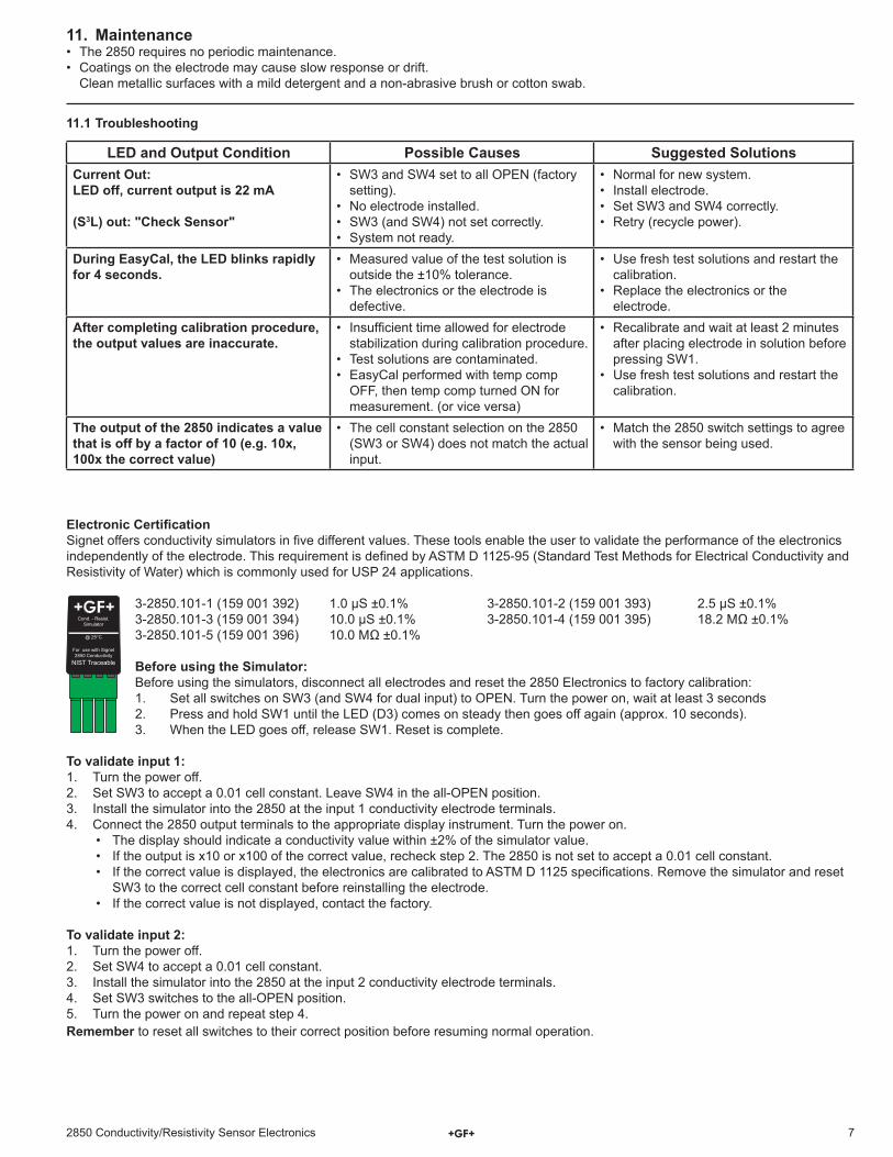
Electronic Certifi cationSignet offers conductivity simulators in fi ve different values. These tools enable the user to validate the performance of the electronics independently of the electrode. This requirement is defi ned by ASTM D 1125-95 (Standard Test Methods for Electrical Conductivity and Resistivity of Water) which is commonly used for USP 24 applications.
3-2850.101-1 (159 001 392) 1.0 μS ±0.1% 3-2850.101-2 (159 001 393) 2.5 μS ±0.1%3-2850.101-3 (159 001 394) 10.0 μS ±0.1% 3-2850.101-4 (159 001 395) 18.2 MΩ ±0.1%3-2850.101-5 (159 001 396) 10.0 MΩ ±0.1%
Before using the Simulator:Before using the simulators, disconnect all electrodes and reset the 2850 Electronics to factory calibration:1. Set all switches on SW3 (and SW4 for dual input) to OPEN. Turn the power on, wait at least 3 seconds2. Press and hold SW1 until the LED (D3) comes on steady then goes off again (approx. 10 seconds).3. When the LED goes off, release SW1. Reset is complete.
To validate input 1:1. Turn the power off.2. Set SW3 to accept a 0.01 cell constant. Leave SW4 in the all-OPEN position.3. Install the simulator into the 2850 at the input 1 conductivity electrode terminals.4. Connect the 2850 output terminals to the appropriate display instrument. Turn the power on.
• The display should indicate a conductivity value within ±2% of the simulator value.• If the output is x10 or x100 of the correct value, recheck step 2. The 2850 is not set to accept a 0.01 cell constant.• If the correct value is displayed, the electronics are calibrated to ASTM D 1125 specifi cations. Remove the simulator and reset
SW3 to the correct cell constant before reinstalling the electrode.• If the correct value is not displayed, contact the factory.
To validate input 2:1. Turn the power off.2. Set SW4 to accept a 0.01 cell constant.3. Install the simulator into the 2850 at the input 2 conductivity electrode terminals.4. Set SW3 switches to the all-OPEN position.5. Turn the power on and repeat step 4.Remember to reset all switches to their correct position before resuming normal operation.
11.1 Troubleshooting
11. Maintenance• The 2850 requires no periodic maintenance.• Coatings on the electrode may cause slow response or drift.
Clean metallic surfaces with a mild detergent and a non-abrasive brush or cotton swab.
Cond. - Resist.Simulator
@ 25°C
For use with Signet 2850 Conductivity
NIST Traceable
LED and Output Condition Possible Causes Suggested SolutionsCurrent Out:LED off, current output is 22 mA
(S3L) out: "Check Sensor"
• SW3 and SW4 set to all OPEN (factory setting).
• No electrode installed.• SW3 (and SW4) not set correctly.• System not ready.
• Normal for new system.• Install electrode.• Set SW3 and SW4 correctly.• Retry (recycle power).
During EasyCal, the LED blinks rapidly for 4 seconds.
• Measured value of the test solution is outside the ±10% tolerance.
• The electronics or the electrode is defective.
• Use fresh test solutions and restart the calibration.
• Replace the electronics or the electrode.
After completing calibration procedure, the output values are inaccurate.
• Insuffi cient time allowed for electrode stabilization during calibration procedure.
• Test solutions are contaminated.• EasyCal performed with temp comp
OFF, then temp comp turned ON for measurement. (or vice versa)
• Recalibrate and wait at least 2 minutes after placing electrode in solution before pressing SW1.
• Use fresh test solutions and restart the calibration.
The output of the 2850 indicates a value that is off by a factor of 10 (e.g. 10x, 100x the correct value)
• The cell constant selection on the 2850 (SW3 or SW4) does not match the actual input.
• Match the 2850 switch settings to agree with the sensor being used.
Georg Fischer Signet LLC, 3401 Aerojet Avenue, El Monte, CA 91731-2882 U.S.A. • Tel. (626) 571-2770 • Fax (626) 573-2057For Worldwide Sales and Service, visit our website: www.gfsignet.com • Or call (in the U.S.): (800) 854-4090For the most up-to-date information, please refer to our website at www.gfsignet.com
3-2850.090-1 Rev. H 06/12 English © Georg Fischer Signet LLC 2012
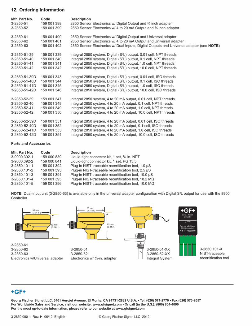
12. Ordering Information
Mfr. Part No. Code Description3-2850-51 159 001 398 2850 Sensor Electronics w/ Digital Output and ¾ inch adapter3-2850-52 159 001 399 2850 Sensor Electronics w/ 4 to 20 mA Output and ¾ inch adapter
3-2850-61 159 001 400 2850 Sensor Electronics w/ Digital Output and Universal adapter3-2850-62 159 001 401 2850 Sensor Electronics w/ 4 to 20 mA Output and Universal adapter3-2850-63 159 001 402 2850 Sensor Electronics w/ Dual Inputs, Digital Outputs and Universal adapter (see NOTE)
3-2850-51-39 159 001 339 Integral 2850 system, Digital (S3L) output, 0.01 cell, NPT threads3-2850-51-40 159 001 340 Integral 2850 system, Digital (S3L) output, 0.1 cell, NPT threads3-2850-51-41 159 001 341 Integral 2850 system, Digital (S3L) output, 1.0 cell, NPT threads3-2850-51-42 159 001 342 Integral 2850 system, Digital (S3L) output, 10.0 cell, NPT threads
3-2850-51-39D 159 001 343 Integral 2850 system, Digital (S3L) output, 0.01 cell, ISO threads3-2850-51-40D 159 001 344 Integral 2850 system, Digital (S3L) output, 0.1 cell, ISO threads3-2850-51-41D 159 001 345 Integral 2850 system, Digital (S3L) output, 1.0 cell, ISO threads3-2850-51-42D 159 001 346 Integral 2850 system, Digital (S3L) output, 10.0 cell, ISO threads
3-2850-52-39 159 001 347 Integral 2850 system, 4 to 20 mA output, 0.01 cell, NPT threads3-2850-52-40 159 001 348 Integral 2850 system, 4 to 20 mA output, 0.1 cell, NPT threads3-2850-52-41 159 001 349 Integral 2850 system, 4 to 20 mA output, 1.0 cell, NPT threads3-2850-52-42 159 001 350 Integral 2850 system, 4 to 20 mA output, 10.0 cell, NPT threads
3-2850-52-39D 159 001 351 Integral 2850 system, 4 to 20 mA output, 0.01 cell, ISO threads3-2850-52-40D 159 001 352 Integral 2850 system, 4 to 20 mA output, 0.1 cell, ISO threads3-2850-52-41D 159 001 353 Integral 2850 system, 4 to 20 mA output, 1.0 cell, ISO threads3-2850-52-42D 159 001 354 Integral 2850 system, 4 to 20 mA output, 10.0 cell, ISO threads
Parts and Accessories
Mfr. Part No. Code Description3-9000.392-1 159 000 839 Liquid-tight connector kit, 1 set, 1/2 in. NPT3-9000.392-2 159 000 841 Liquid-tight connector kit, 1 set, PG 13.53-2850.101-1 159 001 392 Plug-in NIST-traceable recertifi cation tool, 1.0 μS3-2850.101-2 159 001 393 Plug-in NIST-traceable recertifi cation tool, 2.5 μS3-2850.101-3 159 001 394 Plug-in NIST-traceable recertifi cation tool, 10.0 μS3-2850.101-4 159 001 395 Plug-in NIST-traceable recertifi cation tool, 18.2 MΩ3-2850.101-5 159 001 396 Plug-in NIST-traceable recertifi cation tool, 10.0 MΩ
82 mm(3.24 in.)
95 mm(3.74 in.)
85 mm(3.34 in.)
95 mm(3.74 in.)
3-2850-613-2850-623-2850-63Electronics w/Universal adapter
3-2850-513-2850-52Electronics w/ ¾-in. adapter
3-2850-51-XX3-2850-52-XXIntegral System
Cond. - Resist.Simulator
@ 25°C
For use with Signet 2850 Conductivity
NIST Traceable
3-2850.101-XNIST-traceable recertifi cation tool
NOTE: Dual-input unit (3-2850-63) is available only in the universal adapter confi guration with Digital S3L output for use with the 8900 Controller.