Embed Size (px)
Citation preview
SIGNATURE STRUCTURE
FOR THE WOODROW
WILSON MEMORIAL
BRIDGE
Nicholas Edwards, PE
Ahmad Khashan, PE
Greg Shafer, PE
BIOGRAPHY Nicholas Edwards is a Project Engineer for the New York office of Parsons. He has 5 years of experience, and he holds a Masters of Science in Engineering from Princeton University and a Bachelor of Science from Carnegie Mellon University. He is currently the Project Engineer for the Seismic Assessment and Retrofitting of the Brooklyn Bridge. Ahmad Khashan is a Principal Structural Engineer with Parsons. He has over 20 years of experience in the design and rehabilitation design of transportation infrastructures. Mr. Khashan holds a Bachelor Degree in Civil Engineering and a Master Degree of Science from George Washington University. He is currently the Project Manager on several bridge projects in the District of Columbia. Greg Shafer is Senior Engineering Manager for the southeast region of Parsons’ Bridge and Tunnel Division. He has been working in the field of bridge design and construction for 20 years and is currently serving as Project Manager for the design team on the replacement of the Woodrow Wilson Memorial Bridge. Greg graduated from the University of Delaware with a Bachelor of Science in Civil Engineering degree and has also earned a Master of Science Degree from the University of Colorado.
SUMMARY As the winner of a design competition held in 1998, PARSONS was selected to design a replacement bridge for the Potomac crossing on the I-95 / I-495 Capital Beltway. The new 6075 foot-long bridge will carry 12 lanes of traffic and will have 35 spans crossing the river. The signature bridge is an elegant, horizontally curved, haunched plate girder bridge supported by V-shaped piers. The combination of the V-piers and the girder haunches highlights the architectural motif of arches desired by the public. The steel plate girder/ diaphragm/ substringer framing system was adapted to a previously designed substructure with only minimal changes to the substructure design. The project includes two parallel bridges each consisting of 8 plate girders and 3 to 4 substringers to accommodate widths of up to 148 feet. A double-leaf bascule structure (eight leafs total) spans the navigation channel and will become the largest moveable span in the United States. The outer loop structure of the new Woodrow Wilson Bridge is scheduled to be opened for traffic in August, 2006. After demolition of the existing bridge, the inner loop structure will be completed (scheduled for 2008). It is anticipated that the structural systems used for this monumental new bridge will serve the public well for the next 100 years.
SIGNATURE STRUCTURE FOR THE WOODROW WILSON MEMORIAL BRIDGE
by Nicholas Edwards, Ahmad Khashan, and Greg Shafer
INTRODUCTION The aging Woodrow Wilson Bridge carries almost 200,000 vehicles per day across the Potomac River on the I-95 / I-495 Capital Beltway. In response to projected increases of volume to 300,000 vehicles per day and rapidly deteriorating conditions of the existing bridge, the Federal Highway Administration, Virginia, Maryland, and the District of Columbia began to study the replacement of the bridge in 1988. Because of strong local opposition during the original selection process, heavy public involvement including a design competition was incorporated into the selection process. As the winner of the design competition in 1998, PARSONS was selected to design the signature bridge. The new 6075 foot-long bridge will carry 12 lanes of traffic and will have 35 spans crossing the Potomac River. The Woodrow Wilson Bridge project includes a
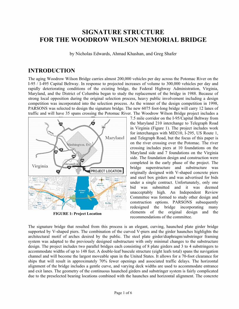
7.5 mile corridor on the I-95/Capital Beltway from the Maryland 210 interchange to Telegraph Road in Virginia (Figure 1). The project includes work for interchanges with MD210, I-295, US Route 1, and Telegraph Road, but the focus of this paper is on the river crossing over the Potomac. The river crossing includes piers at 10 foundations on the Maryland side and 7 foundations on the Virginia side. The foundation design and construction were completed in the early phase of the project. The bridge superstructure and substructure was originally designed with V-shaped concrete piers and steel box girders and was advertised for bids under a single contract. Unfortunately, only one bid was submitted and it was deemed unacceptably high. An Independent Review Committee was formed to study other design and construction options. PARSONS subsequently redesigned the bridge incorporating many elements of the original design and the recommendations of the committee.
FIGURE 1: Project Location
The signature bridge that resulted from this process is an elegant, curving, haunched plate girder bridge supported by V-shaped piers. The combination of the curved V-piers and the girder haunches highlights the architectural motif of arches desired by the public. The steel plate girder/diaphragm/substringer framing system was adapted to the previously designed substructure with only minimal changes to the substructure design. The project includes two parallel bridges each consisting of 8 plate girders and 3 to 4 substringers to accommodate widths of up to 148 feet. A double-leaf bascule structure (eight leafs total) spans the navigation channel and will become the largest moveable span in the United States. It allows for a 70-foot clearance for ships that will result in approximately 70% fewer openings and associated traffic delays. The horizontal alignment of the bridge includes a gentle curve, and varying deck widths are used to accommodate entrance and exit lanes. The geometry of the continuous haunched girders and substringer system is fairly complicated due to the preselected bearing locations combined with the haunches and horizontal alignment. The concrete
Page 1 of 6
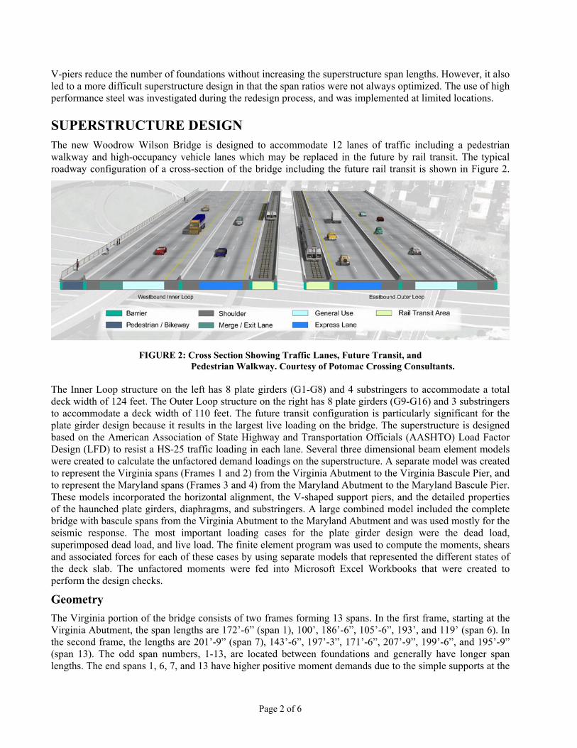
V-piers reduce the number of foundations without increasing the superstructure span lengths. However, it also led to a more difficult superstructure design in that the span ratios were not always optimized. The use of high performance steel was investigated during the redesign process, and was implemented at limited locations. SUPERSTRUCTURE DESIGN The new Woodrow Wilson Bridge is designed to accommodate 12 lanes of traffic including a pedestrian walkway and high-occupancy vehicle lanes which may be replaced in the future by rail transit. The typical roadway configuration of a cross-section of the bridge including the future rail transit is shown in Figure 2.
The Inner Loop structure on the left has 8 plate girders (G1-G8) and 4 substringers to accommodate a total deck width of 124 feet. The Outer Loop structure on the right has 8 plate girders (G9-G16) and 3 substringers to accommodate a deck width of 110 feet. The future transit configuration is particularly significant for the plate girder design because it results in the largest live loading on the bridge. The superstructure is designed based on the American Association of State Highway and Transportation Officials (AASHTO) Load Factor Design (LFD) to resist a HS-25 traffic loading in each lane. Several three dimensional beam element models were created to calculate the unfactored demand loadings on the superstructure. A separate model was created to represent the Virginia spans (Frames 1 and 2) from the Virginia Abutment to the Virginia Bascule Pier, and to represent the Maryland spans (Frames 3 and 4) from the Maryland Abutment to the Maryland Bascule Pier. These models incorporated the horizontal alignment, the V-shaped support piers, and the detailed properties of the haunched plate girders, diaphragms, and substringers. A large combined model included the complete bridge with bascule spans from the Virginia Abutment to the Maryland Abutment and was used mostly for the seismic response. The most important loading cases for the plate girder design were the dead load, superimposed dead load, and live load. The finite element program was used to compute the moments, shears and associated forces for each of these cases by using separate models that represented the different states of the deck slab. The unfactored moments were fed into Microsoft Excel Workbooks that were created to perform the design checks.
FIGURE 2: Cross Section Showing Traffic Lanes, Future Transit, and Pedestrian Walkway. Courtesy of Potomac Crossing Consultants.
Geometry The Virginia portion of the bridge consists of two frames forming 13 spans. In the first frame, starting at the Virginia Abutment, the span lengths are 172’-6” (span 1), 100’, 186’-6”, 105’-6”, 193’, and 119’ (span 6). In the second frame, the lengths are 201’-9” (span 7), 143’-6”, 197’-3”, 171’-6”, 207’-9”, 199’-6”, and 195’-9” (span 13). The odd span numbers, 1-13, are located between foundations and generally have longer span lengths. The end spans 1, 6, 7, and 13 have higher positive moment demands due to the simple supports at the
Page 2 of 6

expansion joints. On the Maryland side, there are also two frames which form spans 17 through 35. Starting from the bascule pier, frame 3 has span lengths of 196’-6” (span 17), 199’-6”, 209’, 188’6”, 199’-9”, 178’, 197’-6”, 166’, and 199’-9” (span 25). Frame 4 has span lengths of 154’-3” (span 26), 189’, 142’-9”, 191’-3”, 130’-6, 191’-9”, 118’, 186’-6”, 105’, and 175’ (span 35) ending at the Maryland Abutment. Again, the longer spans are the odd numbered spans which fall between foundations, and there are four end spans (17, 25, 26, and 35) which have higher positive moment demands due to the simple supports. The haunched plate girders have maximum depths of 11’-9” webs at the bearing locations and 6’-10” webs at the midspan locations. The consistent choice of these web depths throughout all spans of the bridge leads to a consistent visual impact and also it influences the possible design parameters. With the girder depths pre-assigned the remaining design was based on optimizing the plate thicknesses in a cost-effective manner. Microsoft Excel Spreadsheets were created to calculate the three-dimensional geometry of the plate girder and substringer lines. This geometry was formatted into the appropriate syntax of the finite element program and used as input. Typically, the calculation started at the baseline of the bridge and then added horizontal offsets to reach the appropriate girder lines. The analytical geometry was also cross-checked with the corresponding work that was done for the CADD drawings by exporting the data from excel into Microstation.
Plate Girder Design The plate girders are in negative bending at the bearing locations and are designed as non-composite sections. For the longer spans, the midspan locations are in positive dead load bending and are designed as composite sections for live load and service dead loads. Since the bottom flange demands were highest and the shear demands were low, HPS70w was selected for the bottom flange at most of these locations. For the shorter spans (above the piers), the girders are completely in negative bending and are designed as noncomposite sections. The plate girders are continuous over the bearings except at the 6 expansion joints at the abutments, the bascule piers, and two intermediate locations. The field splices were located based on the constraints of roughly 115 feet shipping lengths and minimum design loads. Within each shipping piece the flange widths were held constant and the flange thicknesses were changed with welded shop splices. Thickness transitions were initially determined based on demand requirements and were then modified based on cost efficiencies. When the cost of the additional material of steel did not offset the estimated cost of the welded transition, the thicker plate was extended. The plate girders were braced by intermediate and pier diaphragms which were spaced at a maximum of 25 feet. The sections were classified as non-compact because minimum web thicknesses were chosen to save a maximum amount of material in the webs. The limiting depth to thickness ratios of the web was determined so that no sections would require longitudinal stiffeners. A 7/8” thickness web was determined for the largest depth locations at the bearings and a reduced 5/8” web was utilized at locations where the depth was less than at least 100”. This resulted in a web that satisfied a depth to thickness ratio of roughly 163. The plate girder bending design was generally governed by either a dead load combination which considered the unbraced top flange construction condition or the maximum group I loading considering 1.3 (DL + SDL + 1.67 LL). The allowable compression flange stresses were determined based on the lateral torsional buckling of the flange and the spacing of the diaphragms, and they were generally above 40 ksi. When the allowable stresses were too low, an increase in the flange width was made to improve the lateral buckling of the flange. The size of the top flanges in the longer positive moment spans was dictated by the constructability requirements of AASHTO to insure that lateral-torsional buckling would not occur during construction. The analysis of these critical positive bending moments was determined by incorporating the pouring sequence of the bridge. To minimize cracking in the deck the positive moment portions of the bridge are poured first followed by the negative moment regions. This results, in some cases, in a temporary increase of the positive moment during construction. The unbraced top flange of the plate girders was designed to accommodate these worst case positive moments which occur before the deck has hardened. An additional complication for the design of the fascia girders was large deck overhangs that could result in large torsional demands depending on how the contractor decided to support the deck. The fascia girders were checked with the combination of the pouring sequence positive moment pours and the torsional demands of the large cantilever overhangs to insure that the bridge would be constructable. Additional temporary bracing was required in some cases and laid out in the specifications.
Page 3 of 6

The shear design of the plate girders was predominantly dictated by the minimum web thickness requirement to avoid longitudinal stiffeners in the web as previously described. For the most part, due to the fairly large depth of the webs (11’-9” at the bearings), the shear capacity of the webs was sufficient to avoid any kind of interaction between shear capacity and bending. That is to say the shear demand did not exceed 0.6 of the shear capacity in almost all cases. The use of high performance steel was avoided in the regions of high shear demand (at the bearings) because of the significant penalty in shear capacity with hybrid designs. This penalty is the removal of the tension-field action from the shear capacity which often accounts for a large portion of the capacity.
The fatigue design of the plate girders was checked based on a fatigue category C which was present due to the weld of the toe of transverse stiffeners and connection plates to the plate girders. This resulted in allowable stresses of 21 ksi of 500,000 cycles of HS20 lane loading, 13 ksi for 2,000,000 cycles of HS20 truck loading, and 12 ksi for over 2,000,000 cycles of a single HS20 truck. Separate load cases were setup and run in the finite element program to represent the different fatigue cases. Generally, it was found that the 2,000,000 cycles of HS20 truck loading was controlling, and in some cases it influenced the allowable size of plates near the dead load inflection points.
Diaphragms
The term diaphragms will be used here to refer to the intermediate and pier diaphragms which also act as floor beams to support the sub-stringers between adjacent girders. The diaphragms are spaced at a maximum of 25 ft which is in accordance with standard AASHTO requirement for similar bridges. Typically diaphragms for straight bridges are considered secondary members and are designed to carry wind loads and provide bracing against lateral buckling of the girder’s flanges prior to hardening of the concrete deck. The capacity of the diaphragms to distribute loads transversely between girders is often ignored by bridge designers. For the Woodrow Wilson Bridge, the intermediate diaphragms are primary load carrying members. They are designed to carry the loads from the sub-stringers in addition to carrying wind load and bracing the flanges against lateral buckling. In the negative moment region where the bottom flange of the main girders are in compression, the connection plates between the intermediate diaphragms and the girder web are used to provide the restraint against lateral buckling of the bottom flange. One other important owner requirement is that the bridge be designed for future redecking. This requirement was later turned out to be the controlling load case for the design of the intermediate diaphragms. In order to understand the behavior of the diaphragms under the different load cases and make use of their full capacities, all diaphragms were included in the bridge structural model.
After studying several options, plate diaphragms were chosen as the most adaptable means to support the sub-stringers and provide the necessary framing component for the bridge. The top of the diaphragms was set in the same plane as the top of the longitudinal girders and sub-stringers. This approach served two primary purposes. One is to provide the necessary continuity for the top flange of the diaphragm and the sub-stringers as will be discussed later. The second purpose is to provide rigid horizontal connections between the deck slab and all major longitudinal and transverse load carrying members of the framing system. The two way composite behavior also helps to carry the horizontal loads through the deck back into the piers. The web of the intermediate diaphragms was set at 5’-3” constant depth across the width of the bridge. This dimension was controlled by the presence of the longitudinal concrete tie beams between the interior girders that connect both legs of the V-shaped piers. The pier diaphragms were full girder depth except for those diaphragms that straddle over the concrete pier knuckle. The lengths of the diaphragms which are controlled by the girder spacing varies from 9’-6” at the typical girder spacing to as much as 40’-6” at the Virginia abutment. The longer diaphragms in the wider girder spacing section of the bridge are designed to carry two sub-stringers between two adjacent girders.
In order to effectively distribute loads between girders and resist the imposed forces from the different load cases, the diaphragms had to be designed and constructed continuous across the width of the bridge. Providing continuity for the diaphragms across the width of the bridge required connecting the top and bottom
Page 4 of 6
flanges of the diaphragms on both sides of the interior plate girders. This was accomplished by using a strap plate to connect the top flanges of the diaphragms on both sides of the girder. The strap plate was stitched to the top flange of the girder to provide full contact and prevent moisture entrapment. The bottom flanges of the diaphragms were connected on both sides of the main girder web by a built up tee sections. The stems of the tees are connected with high strength bolts in single shear to the bottom flanges of the diaphragms. The flanges of the tee sections are connected back to back with high strength bolts which pass thru the web of the main girders. At the fascia girders the diaphragms were connected by a partial moment connection through the web only.
Sub-Stringers
One of the Independent Review Committee recommendations is to use steel plate girders in lieu of box girders without significant modifications to the pier design. This recommendation resulted in an unusually challenging girder spacing that varies from 9’-6” to 40’-6”. The required concrete deck slab thickness and the associated selfweight would be prohibitive for the larger girder spacing. In order to address the large girder spacing, several other options were looked into before choosing the sub-stringer diaphragm as the most adequately adaptable framing system. There are four and three sub-stringers in the Inner and Outer Loops of the Woodrow Wilson Bridge respectively. The spacing of the sub-stringers is approximately 9’-6” except for the section of the bridge adjacent to the Virginia abutment where the spacing reaches a maximum of 13’-6”. Not only did the sub-stringers provide the needed support for the deck slab and reduced the required deck slab thickness, it also reduced the overall weight of the structure which was critical since the foundation was completed. The girder-diaphragm–sub-stringer proved also to be an economical bridge framing system.
The typical sub-stringer section consists of a 27 in deep wide flange beam designed to act composite with the deck slab. Although the sub-stringers are supported at the diaphragms which are spaced at approximately 25
foot on center, the actual structural behavior of the sub-stringers mimic and governed by the global behavior of the main girders in the bridge. The neutral axis of the sub-stringers is located above and at variable distance from the neutral axis of the main girders. As such, the sub-stringers are subjected to large axial forces in addition to bending and shear. In the negative moment region over the piers and over the short pier spans, the sub-stringers are subjected to tension forces which are designed to be carried by the steel section only. In the positive moment region, the force in the sub-stringer reverses to compression and therefore was designed to be carried by the composite section of the steel and concrete deck.
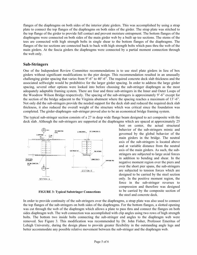
In order to provide continuity of the sub-stringers over the diaphragms, a strap plate was also used to connect the top flanges of the sub-stringers on both sides of the diaphragms. For the bottom flanges, a slotted opening was cut through the web of the diaphragm which allows a plate to pass thru and connect the flanges on both sides diaphragm web. The web connection was accomplished with clip angles using two rows of high strength bolts. The bottom two inside bolts connecting the sub-stringer end angles to the diaphragm web were removed. See Figure 3. This modification was recommended by Dr. John Fisher, Professor Emeritus of Lehigh University, during the design phase to provide greater flexibility in the outstanding angle legs and better accommodate any possible relative movement between the sub-stringer and the diaphragm web.
FIGURE 3: Typical Substringer Connections
Page 5 of 6
Page 6 o
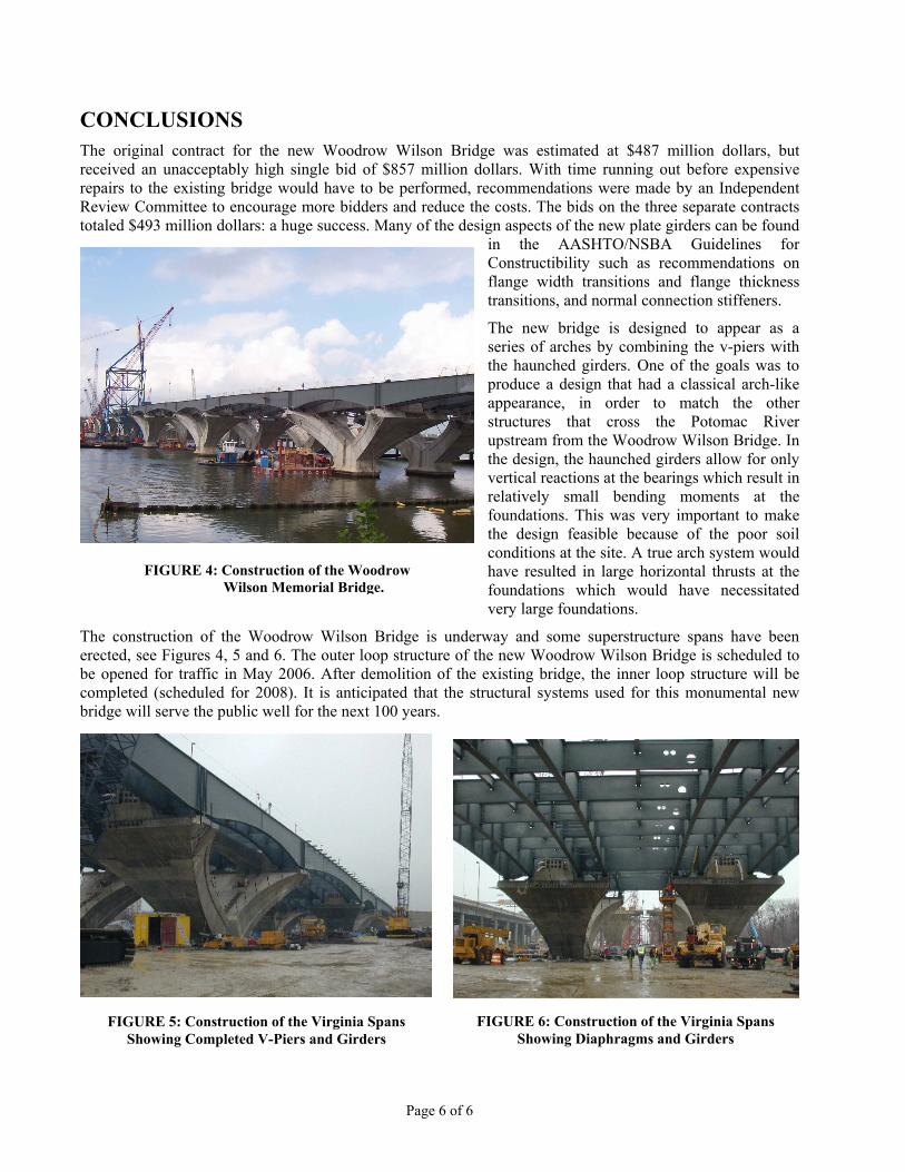
CONCLUSIONS The original contract for the new Woodrow Wilson Bridge was estimated at $487 million dollars, but received an unacceptably high single bid of $857 million dollars. With time running out before expensive repairs to the existing bridge would have to be performed, recommendations were made by an Independent Review Committee to encourage more bidders and reduce the costs. The bids on the three separate contracts totaled $493 million dollars: a huge success. Many of the design aspects of the new plate girders can be found
in the AASHTO/NSBA Guidelines for Constructibility such as recommendations on flange width transitions and flange thickness transitions, and normal connection stiffeners.
FIGURE 4: Construction of the Woodrow Wilson Memorial Bridge.
The new bridge is designed to appear as a series of arches by combining the v-piers with the haunched girders. One of the goals was to produce a design that had a classical arch-like appearance, in order to match the other structures that cross the Potomac River upstream from the Woodrow Wilson Bridge. In the design, the haunched girders allow for only vertical reactions at the bearings which result in relatively small bending moments at the foundations. This was very important to make the design feasible because of the poor soil conditions at the site. A true arch system would have resulted in large horizontal thrusts at the foundations which would have necessitated very large foundations.
f 6
The construction of the Woodrow Wilson Bridge is underway and some superstructure spans have been erected, see Figures 4, 5 and 6. The outer loop structure of the new Woodrow Wilson Bridge is scheduled to be opened for traffic in May 2006. After demolition of the existing bridge, the inner loop structure will be completed (scheduled for 2008). It is anticipated that the structural systems used for this monumental new bridge will serve the public well for the next 100 years.
FIGURE 5: Construction of the Virginia Spans Showing Completed V-Piers and Girders
FIGURE 6: Construction of the Virginia Spans Showing Diaphragms and Girders

Courtesy of National Steel Bridge Alliance; paper presented at 2005 World Steel Bridge Symposium & Workshop.
![Distortional analysis of simply supported box girders with ......lar conclusions can be drawn for straight multi-cell box girders with diaphragms [18,19]. For horizontally curved bridges,](https://img.pdfslide.us/doc/110x75/6145e3178f9ff812541fe9b9/distortional-analysis-of-simply-supported-box-girders-with-lar-conclusions.jpg)