Embed Size (px)
Citation preview
2SIGNALS AND THE PHYSICAL LAYER
2.1 INTRODUCTION
Physical layer is the lowest layer in the OSI reference model. Information can be transmitted or received using cables. The main purpose of the physical layer is to transmit information (data or text or even animated pictures) from a source to a destination. Any form of such information cannot be transmitted as it is, just as in a postal service. Information is transmitted from a source computer to a destination computer in the form of electromagnetic signals using the transmission medium. For example, if you want to transmit a pho-tograph from a source computer to a destination computer, it is rst encoded as a stream of bits 0s and 1s. Then this stream is reconverted as energy in the form of electromagnetic signals. Then only these electromagnetic signals can be transmitted over the network, through a transmission medium. The destination computer receives these signals. They are encoded to the original form. As such signals play a very important role in transmitting information. In view of this, we rst pay our attention to the study of signals and the termi-nology used with respect to signals.
2.2 ANALOG AND DIGITAL SIGNALS
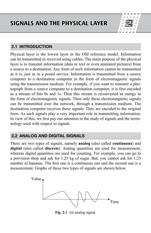
There are two types of signals, namely analog (also called continuous) and digital (also called discrete). Analog quantities are used for measurement, whereas digital quantities are used for counting. For example, you can go to a provision shop and ask for 1.25 kg of sugar. But, you cannot ask for 1.25 number of bananas. The rst one is a continuous one and the second one is a measurement. Graphs of these two types of signals are shown below.
Value
Time
Fig. 2.1 An analog signal.
Chapter 02.indd 33 10/28/2010 11:35:05 AM
Signals and the Physical Layer ♦ 35
Value
Time
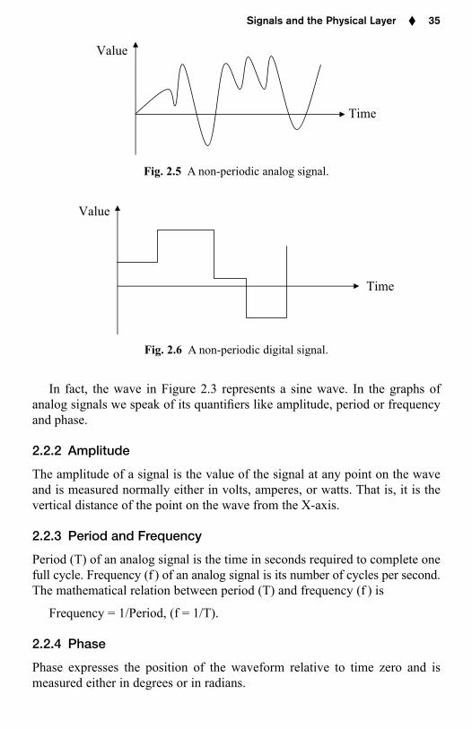
Fig. 2.5 A non-periodic analog signal.
Value
Time
Fig. 2.6 A non-periodic digital signal.
In fact, the wave in Figure 2.3 represents a sine wave. In the graphs of analog signals we speak of its quanti ers like amplitude, period or frequency and phase.
2.2.2 Amplitude
The amplitude of a signal is the value of the signal at any point on the wave and is measured normally either in volts, amperes, or watts. That is, it is the vertical distance of the point on the wave from the X-axis.
2.2.3 Period and Frequency
Period (T) of an analog signal is the time in seconds required to complete one full cycle. Frequency (f ) of an analog signal is its number of cycles per second. The mathematical relation between period (T) and frequency (f ) is
Frequency = 1/Period, (f = 1/T).
2.2.4 Phase
Phase expresses the position of the waveform relative to time zero and is measured either in degrees or in radians.
Chapter 02.indd 35 10/28/2010 11:35:07 AM
Signals and the Physical Layer ♦ 37
The main issues in transmitting data are:
1. Line con guration: The line con guration is concerned about the mode of connecting devices, about the number of devices that use the transmis-sion line, about the problem whether the lines to be shared or limited just to two devices and also whether line is available for transmission or not.
2. Data transmission mode: The transmission mode whether it is one-way or two-way is to be speci ed.
3. Topology: The topology and path used in arranging network devices is to be made clear.
4. Signals: The type of signals used is to be speci ed.5. Encoding: This aspect is about the encoding methods used.6. Interface: Issues regarding the controls to be imposed on what infor-
mation and its amount that can be shared and the method of sharing information by two nearby devices have to be resolved.
7. Medium: The type of the physical medium used is to be decided.
2.3.1 Guided Media
Guided media is the physical connection (cables) between two devices. Mag-netic media, twisted pair of cables, coaxial cables, bre-optic cables come under this category.
2.3.1.1 Magnetic Media
Magnetic media in the form of magnetic tapes or oppy disks is the simplest and widely used transmission technique. One carries these physically from the source to destination. This method is not safe. Also this method is not a good one and the cost involved is prohibitively high, particularly when high bandwidth is used. The density of data transported is less.
2.3.1.2 Twisted Pair of Cables
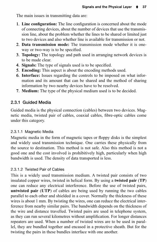
This is a widely used transmission medium. A twisted pair consists of two insulated copper wires, twisted in helical form. By using a twisted pair (TP) one can reduce any electrical interference. Before the use of twisted pairs, untwisted pair (UTP) of cables are being used by running the two cables parallel to each other and shielded in a cover. Normally the thickness of these wires is about 1 mm. By twisting the wires, one can reduce the electrical inter-ference from nearby similar pairs. The bandwidth depends on the thickness of the wire and distance travelled. Twisted pairs are used in telephone system, as they can run several kilometres without ampli cation. For longer distances repeaters are used. When a number of twisted wires are to be used in paral-lel, they are bundled together and encased in a protective sheath. But for the twisting the pairs in these bundles interface with one another.
Chapter 02.indd 37 10/28/2010 11:35:08 AM
38 ♦ Fundamentals of Computer Networks
Color-nodeinsulation
Plasticencasement
Copperconductor
Fig. 2.9 An unshielded four-pair cable.
Color-codeinsulation
ShieldingPlastic
encasementCopper
conductor
Fig. 2.10 Shielded twisted pair.
2.3.1.3 Baseband Coaxial Cables
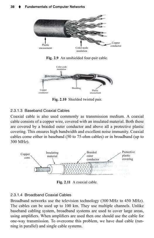
Coaxial cable is also used commonly as transmission medium. A coaxial cable consists of a copper wire, covered with an insulated material. Both these are covered by a braided outer conductor and above all a protective plastic covering. This ensures high bandwidth and excellent noise immunity. Coaxial cables come either in baseband (50 to 75-ohm cables) or in broadband (up to 300 MHz).
Coppercore
Insulatingmaterial
Braidedouterconductor
Protectiveplasticcovering
Fig. 2.11 A coaxial cable.
2.3.1.4 Broadband Coaxial Cables
Broadband networks use the television technology (300 MHz to 450 MHz). The cables can be used up to 100 km. They use multiple channels. Unlike baseband cabling system, broadband systems are used to cover large areas, using ampli ers. When ampli ers are used then one should use the cable for one-way transmission. To overcome this problem, we have dual cable (run-ning in parallel) and single cable systems.
Chapter 02.indd 38 10/28/2010 11:35:08 AM
Signals and the Physical Layer ♦ 39
2.3.1.5 Fibre Optic Cables
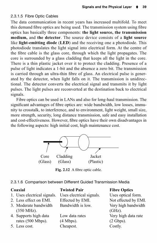
The data communication in recent years has increased multifold. To meet this demand bre optics are being used. The transmission system using bre optics has basically three components: the light source, the transmission medium, and the detector. The source device consists of a light source like light-emitting diode (LED) and the receiving one a photodiode. This photodiode translates the light signal into electrical form. At the centre of the bre cable is the glass core, through which the light propagates. The core is surrounded by a glass cladding that keeps all the light in the core. There is a thin plastic jacket over it to protect the cladding. Presence of a pulse of light indicates a 1-bit and the absence a zero bit. The transmission is carried through an ultra-thin bre of glass. An electrical pulse is gener-ated by the detector, when light falls on it. The transmission is unidirec-tional. The detector converts the electrical signal and transmits it by light pulses. The light pulses are reconverted at the destination back to electrical signals.
Fibre optics can be used in LANs and also for long-haul transmission. The signi cant advantages of bre optics are: wide bandwidth, low losses, immu-nity to crosstalk, to interference, and to environment, light weight, small size, more strength, security, long distance transmission, safe and easy installation and cost-effectiveness. However, bre optics have their own disadvantages in the following aspects: high initial cost, high maintenance cost.
Core(Glass)
Cladding(Glass)
Jacket(Plastic)
Fig. 2.12 A bre optic cable.
2.3.1.6 Comparison between Different Guided Transmission Media
Coaxial Twisted Pair Fibre Optics1. Uses electrical signals. Uses electrical signals. Uses optical form.2. Less effect on EMI. Effected by EMI. Not effected by EMI.3. Moderate bandwidth Bandwidth is low. Very high bandwidth
(350 MHz). (GHz).4. Supports high data Low data rates Very high data rate
rates (500 Mbps). (4 Mbps). (2 Gbps).5. Less cost. Cheapest. Costly.
Chapter 02.indd 39 10/28/2010 11:35:09 AM
40 ♦ Fundamentals of Computer Networks
Coaxial Twisted Pair Fibre Optics6. Repeater spacing is Repeater spacing Spacing between
1–10 km. 2–10 km. 10–100 km.7. Supports all radio Supports all radio Range 902 MHz to
frequencies. frequencies. 928 MHz
2.3.2 Unguided Media
We now consider the unguided transmission media. All the above said types of guided transmission media are not well suited to meet the present-day trans-mission requirements, more particularly of the mobile users and in view of the heavy amount of information that is being exchanged between a number of users either within a network or in between networks. To meet this nat-ural demand, we use the unguided or otherwise called wireless media. In unguided transmission media, no physical conductor (cable) is used. Informa-tion in the form of electromagnetic energy is being transmitted either through air or through water.
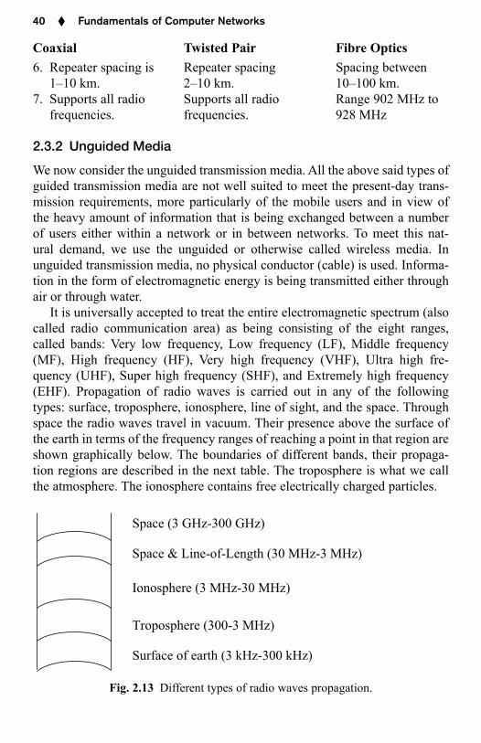
It is universally accepted to treat the entire electromagnetic spectrum (also called radio communication area) as being consisting of the eight ranges, called bands: Very low frequency, Low frequency (LF), Middle frequency (MF), High frequency (HF), Very high frequency (VHF), Ultra high fre-quency (UHF), Super high frequency (SHF), and Extremely high frequency (EHF). Propagation of radio waves is carried out in any of the following types: surface, troposphere, ionosphere, line of sight, and the space. Through space the radio waves travel in vacuum. Their presence above the surface of the earth in terms of the frequency ranges of reaching a point in that region are shown graphically below. The boundaries of different bands, their propaga-tion regions are described in the next table. The troposphere is what we call the atmosphere. The ionosphere contains free electrically charged particles.
Space (3 GHz-300 GHz)
Space & Line-of-Length (30 MHz-3 MHz)
Ionosphere (3 MHz-30 MHz)
Troposphere (300-3 MHz)
Surface of earth (3 kHz-300 kHz)
Fig. 2.13 Different types of radio waves propagation.
Chapter 02.indd 40 10/28/2010 11:35:09 AM
Signals and the Physical Layer ♦ 41
Type of the band Frequency Type of propagation
Very low frequency (VLF) 3 kHz–30 kHz Surface
Low frequency (LF) 30 kHz–300 kHz Surface
Middle frequency (MF) 300 kHz–3 MHz Tropospheric
High frequency (HF) 3 MHz–30 MHz Ionospheric
Very high frequency (VHF) 30 MHz–300 MHz Space & line-of-length
Ultra high frequency (UHF) 300 MHz–3GHz Space & line-of-length
Super high frequency (SHF) 3 GHz–30 GHz Space
Extremely high frequency (EHF) 30 GHz–300 GHz Space
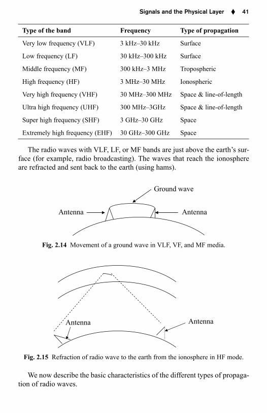
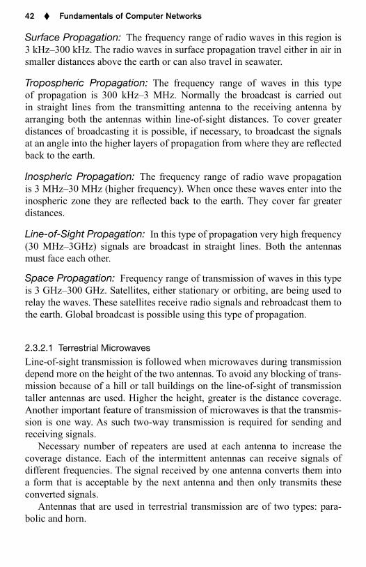
The radio waves with VLF, LF, or MF bands are just above the earth’s sur-face (for example, radio broadcasting). The waves that reach the ionosphere are refracted and sent back to the earth (using hams).
Antenna Antenna
Ground wave
Fig. 2.14 Movement of a ground wave in VLF, VF, and MF media.
Antenna Antenna
Fig. 2.15 Refraction of radio wave to the earth from the ionosphere in HF mode.
We now describe the basic characteristics of the different types of propaga-tion of radio waves.
Chapter 02.indd 41 10/28/2010 11:35:10 AM
42 ♦ Fundamentals of Computer Networks
Surface Propagation: The frequency range of radio waves in this region is 3 kHz–300 kHz. The radio waves in surface propagation travel either in air in smaller distances above the earth or can also travel in seawater.
Tropospheric Propagation: The frequency range of waves in this type of propagation is 300 kHz–3 MHz. Normally the broadcast is carried out in straight lines from the transmitting antenna to the receiving antenna by arranging both the antennas within line-of-sight distances. To cover greater distances of broadcasting it is possible, if necessary, to broadcast the signals at an angle into the higher layers of propagation from where they are re ected back to the earth.
Inospheric Propagation: The frequency range of radio wave propagation is 3 MHz–30 MHz (higher frequency). When once these waves enter into the inospheric zone they are re ected back to the earth. They cover far greater distances.
Line-of-Sight Propagation: In this type of propagation very high frequency (30 MHz–3GHz) signals are broadcast in straight lines. Both the antennas must face each other.
Space Propagation: Frequency range of transmission of waves in this type is 3 GHz–300 GHz. Satellites, either stationary or orbiting, are being used to relay the waves. These satellites receive radio signals and rebroadcast them to the earth. Global broadcast is possible using this type of propagation.
2.3.2.1 Terrestrial Microwaves
Line-of-sight transmission is followed when microwaves during transmission depend more on the height of the two antennas. To avoid any blocking of trans-mission because of a hill or tall buildings on the line-of-sight of transmission taller antennas are used. Higher the height, greater is the distance coverage. Another important feature of transmission of microwaves is that the transmis-sion is one way. As such two-way transmission is required for sending and receiving signals.
Necessary number of repeaters are used at each antenna to increase the coverage distance. Each of the intermittent antennas can receive signals of different frequencies. The signal received by one antenna converts them into a form that is acceptable by the next antenna and then only transmits these converted signals.
Antennas that are used in terrestrial transmission are of two types: para-bolic and horn.
Chapter 02.indd 42 10/28/2010 11:35:10 AM
Signals and the Physical Layer ♦ 43
2.3.2.2 Cellular Phones
The number of persons using cellular phones has been increasing at a rapid rate. Both the moving users may want to communicate with each other or one moving user wants to communicate with a landline telephone. A central serv-ice unit called the server is put to use that identi es the address of the caller and assigns a channel and transmits that call on that channel. As the caller moves, the server transfers the signal from one channel to another channel. For accomplishing this process of changing channels, a geographic region is divided into a number of cells. Each cell has its own frequency range. Each cell that contains an antenna is controlled by an of ce called the cell of ce, which in turn is controlled by a switching of ce. This switching of ce is called a mobile telephone switching of ce (MTSO). The main function of an MSTO is to coordinate communications between all cell of ces.
2.4 THE TELEPHONE SYSTEM
Two computers can be connected by a cable for their communication needs, if they are located close to each other and owned by the same organization. But if the distance between them is large, connecting them by cables poses some problems, mostly legal, as they may have to cross private lands, government roads, etc. The “Public Switched Telephone Network (PSTN)” system is then used. But, their use in the present day is minimal.
The telephone system consists of two parts: the switching of ce and the switches. From the beginning and till recently analog signalling is being used by the telephone systems. But analog signalling is subjected to lot of distortion due to the electrical voltage uctuations. Also time duration to rep-resent different information streams is not uniform. Problems creep in analog transmission due to transmission failures. These problems are identi ed as follows:
Attenuation: This tells the loss of energy (decibels/km) as the signal moves forward. This factor depends on the frequency in signalling. Less the attenuation, better is the signal transmission. Ampli ers can be used to lessen attenuation.
Delay distortion: This is caused because of varied speeds of different components of signals.
Noise: There is noise in transmission because of wasted energy from exter-nal sources. These phenomena cannot be avoided. It may occur due to random motion of electrons, or due to crosstalk across the line.
Because of these problems, wide range of frequencies cannot be accom-modated in signals. The signal’s amplitude, frequency, phase is modulated for a better transmission. In this context one distinguishes between ampli-tude modulation (modulation of voltage levels), frequency modulation
Chapter 02.indd 43 10/28/2010 11:35:10 AM
44 ♦ Fundamentals of Computer Networks
(modulation of different frequency levels of signals) and phase modulation (phase shift). The device used to generate a modulated carrier as output from a signal is called a modem (modulator demodulator). The technology of modems has improved a lot. One can send 9600 bps over a 2400-baud based line. The device used is called quadrature amplitude modulator (QAM).
Nowadays digital signalling is used. Digital signalling has lot of advantages. By using digital regenerators, losses in signals can be avoided and the signals can travel long distances. Voice, data, music and images can be transmitted very effectively using digital signalling. It is much cheaper and is easy to maintain.
2.5 TRANSMISSION MEDIA: SELECTION CRITERIA
There are a number of factors that nally decide the type of transmission media. The main factors are: (1) Attenuation, (2) Electromagnetic interfer-ence, (3) Security, (4) Speed, and (4) Cost. Attenuation means the possibility of a signal to become weak or distorted during transmission. This is to be avoided. The other factors are self-explanatory.
2.6 SWITCHING
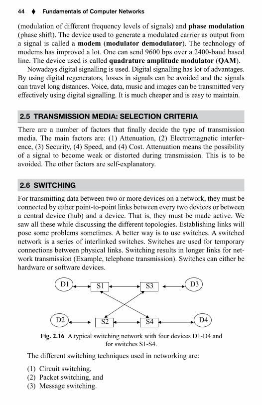
For transmitting data between two or more devices on a network, they must be connected by either point-to-point links between every two devices or between a central device (hub) and a device. That is, they must be made active. We saw all these while discussing the different topologies. Establishing links will pose some problems sometimes. A better way is to use switches. A switched network is a series of interlinked switches. Switches are used for temporary connections between physical links. Switching results in longer links for net-work transmission (Example, telephone transmission). Switches can either be hardware or software devices.
S1 S3
S2 S4
D1
D2
D3
D4
Fig. 2.16 A typical switching network with four devices D1-D4 and for switches S1-S4.
The different switching techniques used in networking are:
(1) Circuit switching,(2) Packet switching, and(3) Message switching.
Chapter 02.indd 44 10/28/2010 11:35:10 AM
Signals and the Physical Layer ♦ 45
2.6.1 Circuit Switching
This technique of circuit switching uses a dedicated line (connection/path) established for transferring data from one device in the network to another. Best example of this type of switching is “telephone”. When you want to talk to your friend using your telephone, you lift the cradle of your tele-phone and press the necessary numbered keys. Then a dedicated path is established between you (source device) and your friend (destination device). When your friend responds (in other words, the receiving device must be ready to receive data from this source device), then you talk to your friend (transfer of data) and then put down the cradle on your phone (disconnect).
The following are the three steps involved in the communication between two devices:
(1) Setting up a connection,(2) Transfer of data, and(3) Terminating the connection.
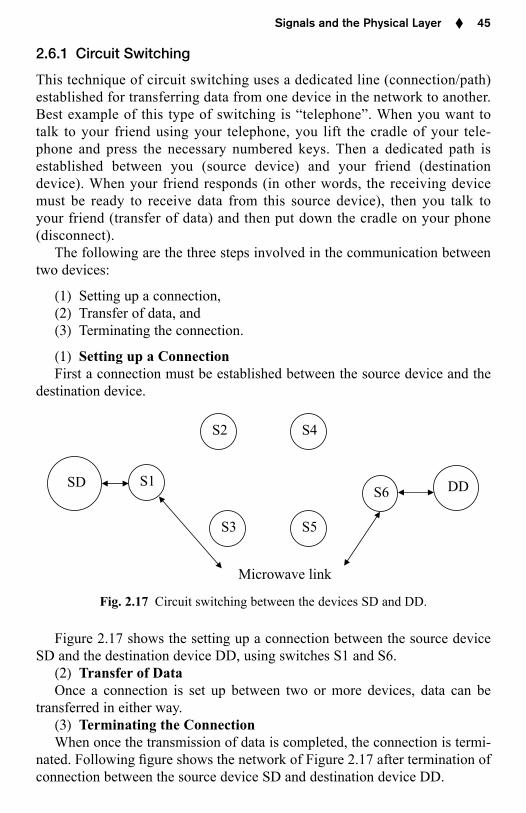
(1) Setting up a ConnectionFirst a connection must be established between the source device and the
destination device.
Microwave link
S1
S2
S3
S4
S5
S6SD DD
Fig. 2.17 Circuit switching between the devices SD and DD.
Figure 2.17 shows the setting up a connection between the source device SD and the destination device DD, using switches S1 and S6.
(2) Transfer of DataOnce a connection is set up between two or more devices, data can be
transferred in either way.(3) Terminating the ConnectionWhen once the transmission of data is completed, the connection is termi-
nated. Following gure shows the network of Figure 2.17 after termination of connection between the source device SD and destination device DD.
Chapter 02.indd 45 10/28/2010 11:35:11 AM
46 ♦ Fundamentals of Computer Networks
Microwave link
S1
S3 S5
S6SD DD
S2 S$
Fig. 2.18 Network after terminating the connection between SD and DD.
Circuit switching is done using either of the following two methods:
(1) Space-division circuit switching, and(2) Time-division circuit switching.
2.6.1.1 Space-Division Circuit Switching
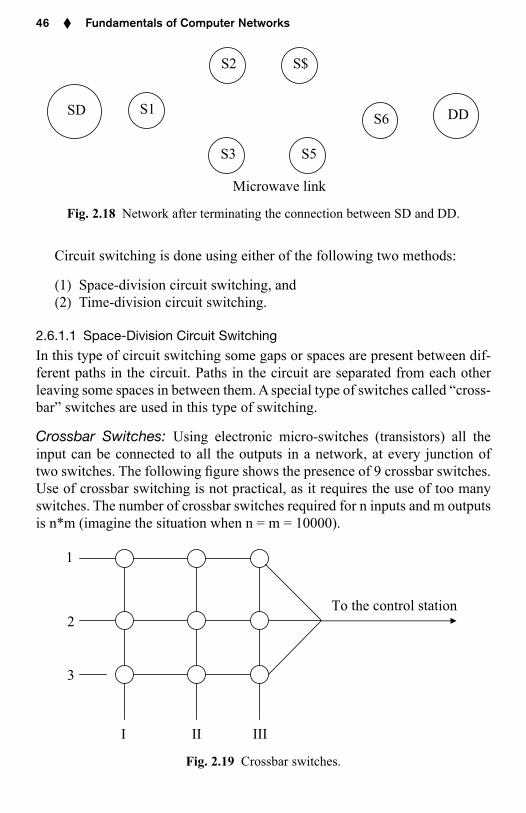
In this type of circuit switching some gaps or spaces are present between dif-ferent paths in the circuit. Paths in the circuit are separated from each other leaving some spaces in between them. A special type of switches called “cross-bar” switches are used in this type of switching.
Crossbar Switches: Using electronic micro-switches (transistors) all the input can be connected to all the outputs in a network, at every junction of two switches. The following gure shows the presence of 9 crossbar switches. Use of crossbar switching is not practical, as it requires the use of too many switches. The number of crossbar switches required for n inputs and m outputs is n*m (imagine the situation when n = m = 10000).
1
To the control station 2
3
I II III
Fig. 2.19 Crossbar switches.
Chapter 02.indd 46 10/28/2010 11:35:11 AM
48 ♦ Fundamentals of Computer Networks
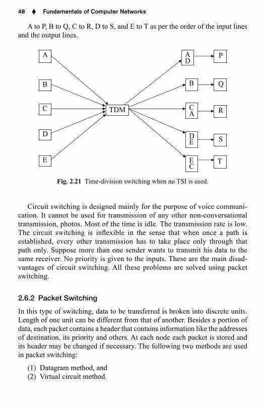
A to P, B to Q, C to R, D to S, and E to T as per the order of the input lines and the output lines.
B
C
D
E
A A P
B Q
C R
D S
E T
TDM
D
A
E
C
Fig. 2.21 Time-division switching when no TSI is used.
Circuit switching is designed mainly for the purpose of voice communi-cation. It cannot be used for transmission of any other non-conversational transmission, photos. Most of the time is idle. The transmission rate is low. The circuit switching is in exible in the sense that when once a path is established, every other transmission has to take place only through that path only. Suppose more than one sender wants to transmit his data to the same receiver. No priority is given to the inputs. These are the main disad-vantages of circuit switching. All these problems are solved using packet switching.
2.6.2 Packet Switching
In this type of switching, data to be transferred is broken into discrete units. Length of one unit can be different from that of another. Besides a portion of data, each packet contains a header that contains information like the addresses of destination, its priority and others. At each node each packet is stored and its header may be changed if necessary. The following two methods are used in packet switching:
(1) Datagram method, and(2) Virtual circuit method.
Chapter 02.indd 48 10/28/2010 11:35:11 AM
Signals and the Physical Layer ♦ 49
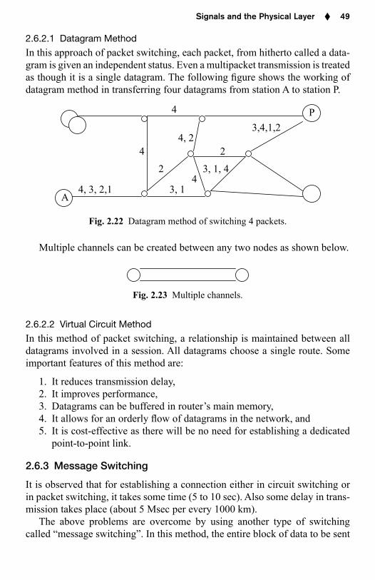
2.6.2.1 Datagram Method
In this approach of packet switching, each packet, from hitherto called a data-gram is given an independent status. Even a multipacket transmission is treated as though it is a single datagram. The following gure shows the working of datagram method in transferring four datagrams from station A to station P.
4
3,4,1,2 4, 2
4 2
2 3, 1, 4 4
4, 3, 2,1 3, 1 A
P
Fig. 2.22 Datagram method of switching 4 packets.
Multiple channels can be created between any two nodes as shown below.
Fig. 2.23 Multiple channels.
2.6.2.2 Virtual Circuit Method
In this method of packet switching, a relationship is maintained between all datagrams involved in a session. All datagrams choose a single route. Some important features of this method are:
1. It reduces transmission delay,2. It improves performance,3. Datagrams can be buffered in router’s main memory,4. It allows for an orderly ow of datagrams in the network, and5. It is cost-effective as there will be no need for establishing a dedicated
point-to-point link.
2.6.3 Message Switching
It is observed that for establishing a connection either in circuit switching or in packet switching, it takes some time (5 to 10 sec). Also some delay in trans-mission takes place (about 5 Msec per every 1000 km).
The above problems are overcome by using another type of switching called “message switching”. In this method, the entire block of data to be sent
Chapter 02.indd 49 10/28/2010 11:35:12 AM
50 ♦ Fundamentals of Computer Networks
by the sender is rst stored in the switching of ce (equivalent of a router) and is then transmitted block by block with one hop at a time. This is called store-and-forward technique.
2.6.4 Comparison between Circuit and Packet Types of Switching
Basis Circuit switching Packet switching1. Transmission Through a
dedicated lineNo dedicated line but through a routing mechanism
2. Bandwidth Fixed Dynamic3. Movement
of dataEntire data is treated as a single unit
Data is divided into smaller units called packets
4. Route followed One single route Different routes if necessary for different packets
5. Call setup Necessary Not necessary6. Occurrence of
congestionAt setup time Whenever a packet
is transmitted7. Transfer rate Fixed Can vary from
packet to packet8. Cost Per unit of time Per packet
2.7 ENCODING ASYNCHRONOUS COMMUNICATIONS
The word encoding means transforming information into signals. The infor-mation is encoded based on a number of factors like its original format and the format used by the communication hardware. The following are the differ-ent types of encoding:
(i) digital-to-digital,(ii) analog-to-digital.(iii) digital-to-analog, and(iv) analog-to-analog.
We now consider these encoding methods.
2.7.1 Digital-to-Digital Encoding
In this type the information is digital and the signal is also digital. Transmitting information from a computer to a printer comes under this type. Information within the computer in 0’s and 1’s is digital and the data transmitted is also digital. Again the different types of digital-to-digital encoding are:
Chapter 02.indd 50 10/28/2010 11:35:12 AM
52 ♦ Fundamentals of Computer Networks
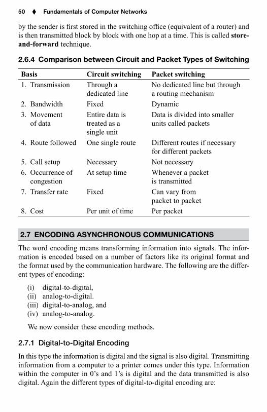
2.7.2 Analog-to-Digital Encoding
Here the information (x-axis) is in analog mode and the signal (y-axis) in digital mode. The process of recording your Professor’s lecture on CD comes under this type. That is, a wave signal is represented as a digital signal.
Fig. 2.24 Analog-to-digital encoding.
It is to be observed that a wave signal is an in nite number of values and a digital signal is a discrete number of values. As such, the analog-to-digital encoding represents an in nite number of values to a discrete number of val-ues. This representation is carried out in the following two phases.
Pulse Amplitude Modulation (PAM): The rst phase, called PAM (Pulse Amplitude Modulation) considers the portions of the wave in equal intervals. Then it records the amplitude of the signal at these selected equal intervals. It divides the wave into a selected list of amplitude values of the wave signal at equal intervals. Such a collection of values is called sampling.
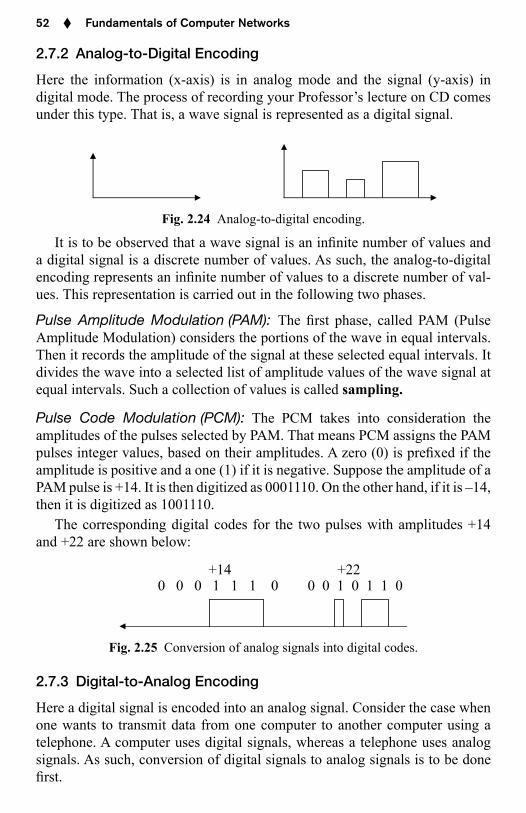
Pulse Code Modulation (PCM): The PCM takes into consideration the amplitudes of the pulses selected by PAM. That means PCM assigns the PAM pulses integer values, based on their amplitudes. A zero (0) is pre xed if the amplitude is positive and a one (1) if it is negative. Suppose the amplitude of a PAM pulse is +14. It is then digitized as 0001110. On the other hand, if it is –14, then it is digitized as 1001110.
The corresponding digital codes for the two pulses with amplitudes +14 and +22 are shown below:
+14 +22 0 0 0 1 1 1 0 0 0 1 0 1 1 0
Fig. 2.25 Conversion of analog signals into digital codes.
2.7.3 Digital-to-Analog Encoding
Here a digital signal is encoded into an analog signal. Consider the case when one wants to transmit data from one computer to another computer using a tele phone. A computer uses digital signals, whereas a telephone uses analog signals. As such, conversion of digital signals to analog signals is to be done rst.
Chapter 02.indd 52 10/28/2010 11:35:12 AM
Signals and the Physical Layer ♦ 53
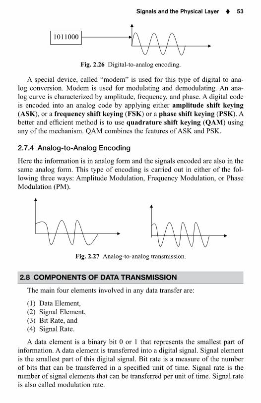
1011000
Fig. 2.26 Digital-to-analog encoding.
A special device, called “modem” is used for this type of digital to ana-log conversion. Modem is used for modulating and demodulating. An ana-log curve is characterized by amplitude, frequency, and phase. A digital code is encoded into an analog code by applying either amplitude shift keying (ASK), or a frequency shift keying (FSK) or a phase shift keying (PSK). A better and ef cient method is to use quadrature shift keying (QAM) using any of the mechanism. QAM combines the features of ASK and PSK.
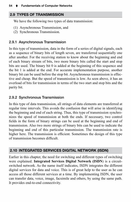
2.7.4 Analog-to-Analog Encoding
Here the information is in analog form and the signals encoded are also in the same analog form. This type of encoding is carried out in either of the fol-lowing three ways: Amplitude Modulation, Frequency Modulation, or Phase Modulation (PM).
Fig. 2.27 Analog-to-analog transmission.
2.8 COMPONENTS OF DATA TRANSMISSION
The main four elements involved in any data transfer are:
(1) Data Element,(2) Signal Element,(3) Bit Rate, and(4) Signal Rate.
A data element is a binary bit 0 or 1 that represents the smallest part of information. A data element is transferred into a digital signal. Signal element is the smallest part of this digital signal. Bit rate is a measure of the number of bits that can be transferred in a speci ed unit of time. Signal rate is the number of signal elements that can be transferred per unit of time. Signal rate is also called modulation rate.
Chapter 02.indd 53 10/28/2010 11:35:13 AM
54 ♦ Fundamentals of Computer Networks
2.9 TYPES OF TRANSMISSION
We have the following two types of data transmission:
(1) Asynchronous Transmission, and(2) Synchronous Transmission.
2.9.1 Asynchronous Transmission
In this type of transmission, data in the form of a series of digital signals, each as a sequence of binary bits of length seven, are transferred sequentially one after another. For the receiving station to know about the beginning and end of each binary stream of bits, two more binary bits called the start and stop bits are used. The binary bit 0 is added at the beginning of this sequence and the bit 1 is added at the end. For accurate implementation purpose, another binary bit can be used before the stop bit. Asynchronous transmission is effec-tive and cheap. But the speed of transmission is low. As seen above, it has an overload of bits for transmission in terms of the two start and stop bits and the parity bit.
2.9.2 Synchronous Transmission
In this type of data transmission, all strings of data elements are transferred at regular time intervals. This avoids the confusion that will arise in identifying the beginning and end of each string. Thus, this type of transmission synchro-nizes the speed of transmission at both the ends. If necessary, two control elds in the form of binary strings can be used at the beginning and end of transmission. Also two more strings of binary bits can be used to indicate the beginning and end of this particular transmission. The transmission rate is higher here. The transmission is ef cient. Sometimes the design of this type of transmission becomes dif cult.
2.10 INTEGRATED SERVICES DIGITAL NETWORK (ISDN)
Earlier in this chapter, the need for switching and different types of switching were explained. Integrated Services Digital Network (ISDN) is a circuit-switched network. As the name itself indicates, ISDN integrates the different digital services for data and voice. This is of great help to the user as he can access all those different services at a time. By implementing ISDN, the user can transfer data, voice, image, facsimile and others, by using the same path. It provides end-to-end connectivity.
Chapter 02.indd 54 10/28/2010 11:35:13 AM
Signals and the Physical Layer ♦ 55
2.10.1 Services Provided by ISDN
The services provided by ISDN are classi ed as:
(1) Bearer services,(2) Teleservices, and(3) Supplementary services.
2.10.1.1 Bearer Services
The basic services demanded by almost all users in a network are transfer of data, voice, and video. Such services are called bearer services as they don’t allow the network to intervene with the information that is being transferred. No processing of the information is carried out. The contents of the infor-mation are not altered. Bearer services can be made available in the physi-cal layer, data link layer, network layer by using circuit-switched circuits (for either voice or data) and packet-switched connections (for data) in increments of 64 kbits/s, frame-relay, or cell-relay networks. A signi cant application of ISDN is Internet access. This application provides a maximum access of 128 kbits/s in both the directions (upward or downward).
2.10.1.2 Teleservices
In bearer ISDN services there is rigidity in transferring data in the sense that the network will not interfere with the data that is transferred and do not change it before or during transmission. In teleservicing the network can mod-ify or apply any process to the information that is transmitted. Some exam-ples of teleservices are: telephony, telex, teleconferencing, telefax, teletex, and videotex.
2.10.1.3 Supplementary Services
These are the services provided by ISDN other than the bearer services and video services. Some of the ISDN supplementary services are: message han-dling, call waiting, and reverse charging.
2.10.2 Subscriber Access to the ISDN and User Interfaces
To meet the heavy demand for data transmission, a number of channels are provided between users and the ISDN. The ISDN standard de nes three chan-nels, each of different transmission rates. They are:
(1) B-Channels,(2) D-Channels, and(3) H-Channels.
Chapter 02.indd 55 10/28/2010 11:35:13 AM
58 ♦ Fundamentals of Computer Networks
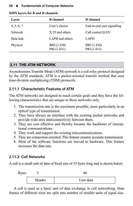
ISDN layers for B and D channels
Layer B channel D channel
4, 5, 6, 7 User’s choice End-to-end user signalling
Network X.25 and others Call control Q.931
Data link LAPB and others LAPD
Physical BRI (1.430)PRI (1.431)
BRI (1.430)PRI (1.431)
2.11 THE ATM NETWORK
Asynchronous Transfer Mode (ATM) network is a cell relay protocol designed by the ATM standards. ATM is a packet-oriented transfer method that uses time-division multiplexing (TDM) protocols.
2.11.1 Characteristic Features of ATM
The ATM networks are designed to reach certain goals and they have the fol-lowing characteristics that are unique to these networks only.
1. The transmission rate is the maximum possible, more particularly in an optical type of transmission.
2. They have always an interface with the existing packet networks and provide wide area interconnectivity between them.
3. They are cost effective and thereby became the backbone of interna-tional communications.
4. They work and support the existing telecommunications.5. They are connection-oriented. This feature ensures accurate transmission.6. Most of the software functions are moved to hardware. This feature
increases the data rate.
2.11.2 Cell Networks
A cell is a small unit of data of xed size of 53 bytes long and is shown below.
Bytes 5 48
Header User data
A cell is used as a basic unit of data exchange in cell networking. Data frames of different sizes are split into number of smaller units of equal size.
Chapter 02.indd 58 10/28/2010 11:35:14 AM
Signals and the Physical Layer ♦ 59
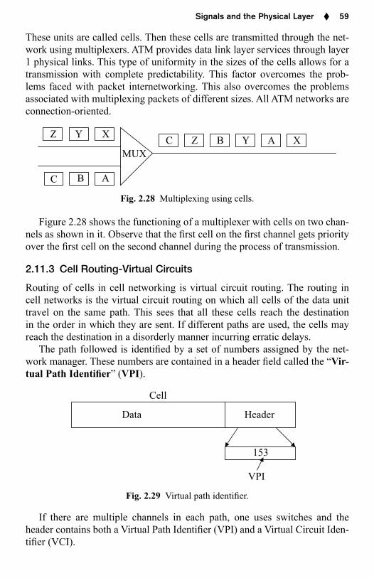
These units are called cells. Then these cells are transmitted through the net-work using multiplexers. ATM provides data link layer services through layer 1 physical links. This type of uniformity in the sizes of the cells allows for a transmission with complete predictability. This factor overcomes the prob-lems faced with packet internetworking. This also overcomes the problems associated with multiplexing packets of different sizes. All ATM networks are connection-oriented.
MUX
Z Y X
C B A
C Z B Y A X
Fig. 2.28 Multiplexing using cells.
Figure 2.28 shows the functioning of a multiplexer with cells on two chan-nels as shown in it. Observe that the rst cell on the rst channel gets priority over the rst cell on the second channel during the process of transmission.
2.11.3 Cell Routing-Virtual Circuits
Routing of cells in cell networking is virtual circuit routing. The routing in cell networks is the virtual circuit routing on which all cells of the data unit travel on the same path. This sees that all these cells reach the destination in the order in which they are sent. If different paths are used, the cells may reach the destination in a disorderly manner incurring erratic delays.
The path followed is identi ed by a set of numbers assigned by the net-work manager. These numbers are contained in a header eld called the “Vir-tual Path Identi er” (VPI).
Cell
Data Header
153
VPI
Fig. 2.29 Virtual path identi er.
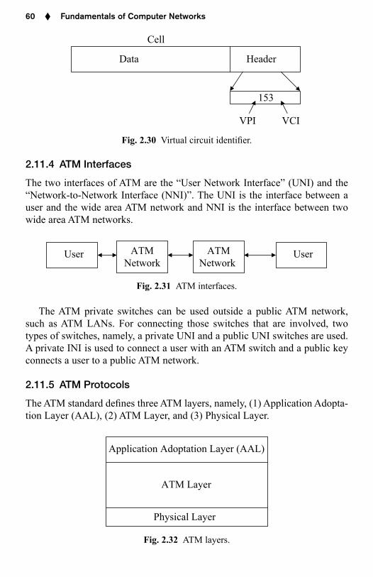
If there are multiple channels in each path, one uses switches and the header contains both a Virtual Path Identi er (VPI) and a Virtual Circuit Iden-ti er (VCI).
Chapter 02.indd 59 10/28/2010 11:35:14 AM
60 ♦ Fundamentals of Computer Networks
Cell
Data Header
153
VPI VCI
Fig. 2.30 Virtual circuit identi er.
2.11.4 ATM Interfaces
The two interfaces of ATM are the “User Network Interface” (UNI) and the “Network-to-Network Interface (NNI)”. The UNI is the interface between a user and the wide area ATM network and NNI is the interface between two wide area ATM networks.
UserUser ATMNetwork
ATMNetwork
Fig. 2.31 ATM interfaces.
The ATM private switches can be used outside a public ATM network, such as ATM LANs. For connecting those switches that are involved, two types of switches, namely, a private UNI and a public UNI switches are used. A private INI is used to connect a user with an ATM switch and a public key connects a user to a public ATM network.
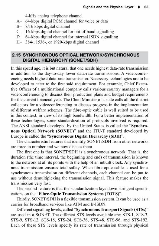
2.11.5 ATM Protocols
The ATM standard de nes three ATM layers, namely, (1) Application Adopta-tion Layer (AAL), (2) ATM Layer, and (3) Physical Layer.
Application Adoptation Layer (AAL)
ATM Layer
Physical Layer
Fig. 2.32 ATM layers.
Chapter 02.indd 60 10/28/2010 11:35:15 AM
Signals and the Physical Layer ♦ 63
4-kHz analog telephone channelA– 64-kbps digital PCM channel for voice or dataB– 8/16 kbps digital channelC– 16-kbps digital channel for out-of-band signallingD– 64-kbps digital channel for internal ISDN signallingH– 384-, 1536-, or 1920-kbps digital channel
2.15 SYNCHRONOUS OPTICAL NETWORK/SYNCHRONOUS DIGITAL HIERARCHY (SONET/SDH)
In this speed age, it is but natural that one needs highest data-rate transmission in addition to the day-to-day lower data-rate transmissions. A videoconfer-encing needs highest data-rate transmission. Necessary technologies are to be developed to cater to the rst said requirement. For example, Chief Execu-tive Of cer of a multinational company calls various country managers for a video conferencing to discuss their production plans and budget requirements for the current nancial year. The Chief Minister of a state calls all the district collectors for a videoconferencing to discuss progress in the implementation of different welfare schemes. The bre-optic cable is well suited to be used in this context, in view of its high bandwidth. For a better implementation of these technologies, some standardization of protocols involved is required. The ANSI standard developed by the United States is called the “Synchro-nous Optical Network (SONET)” and the ITU-T standard developed by Europe is called the “Synchronous Digital Hierarchy (SDH)”.
The characteristic features that identify SONET/SDH from other networks are three in number and we now discuss them.
The rst one is that SONET/SDH is a synchronous network. That is, the duration (the time interval, the beginning and end) of transmission is known to the network at all its points with the help of an inbuilt clock. Any synchro-nous transmission ensures total safety. When bre-optic cable is used for a synchronous transmission on different channels, each channel can be put to use without demultiplexing the transmission signal. This feature makes the transmission very fast.
The second feature is that the standardization lays down stringent speci -cations on the “Fibre-Optic Transmission Systems (FOTS)”.
Thirdly, SONET/SDH is a exible transmission system. It can be used as a carrier for broadband services like ATM and B-ISDN.
Different signalling levels, called “Synchronous Transport Signals (STSs)” are used in a SONET. The different STS levels available are: STS-1, STS-3, STS-9, STS-12, STS-18, STS-24, STS-36, STS-48, STS-96, and STS-192. Each of these STS levels specify its rate of transmission through physical
Chapter 02.indd 63 10/28/2010 11:35:16 AM
Signals and the Physical Layer ♦ 65
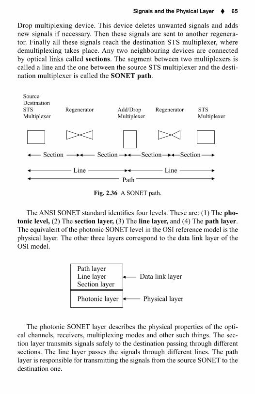
Drop multiplexing device. This device deletes unwanted signals and adds new signals if necessary. Then these signals are sent to another regenera-tor. Finally all these signals reach the destination STS multiplexer, where demultiplexing takes place. Any two neighbouring devices are connected by optical links called sections. The segment between two multiplexers is called a line and the one between the source STS multiplexer and the desti-nation multiplexer is called the SONET path.
Source Destination STS Regenerator Add/Drop Regenerator STS Multiplexer Multiplexer Multiplexer
Section Section Section Section
Line LinePath
Fig. 2.36 A SONET path.
The ANSI SONET standard identi es four levels. These are: (1) The pho-tonic level, (2) The section layer, (3) The line layer, and (4) The path layer. The equivalent of the photonic SONET level in the OSI reference model is the physical layer. The other three layers correspond to the data link layer of the OSI model.
Path layer Line layer Data link layer Section layer
Photonic layer Physical layer
The photonic SONET layer describes the physical properties of the opti-cal channels, receivers, multiplexing modes and other such things. The sec-tion layer transmits signals safely to the destination passing through different sections. The line layer passes the signals through different lines. The path layer is responsible for transmitting the signals from the source SONET to the destination one.
Chapter 02.indd 65 10/28/2010 11:35:16 AM