Embed Size (px)
Citation preview

Signaling Manager User Guide
DESCRIPTION
1553-CNA 403 0874/1 Uen H4

Copyright
© Telefonaktiebolaget LM Ericsson 2005-2010 All Rights Reserved. No part ofthis document may be reproduced in any form without the written permission ofthe copyright owner.
Disclaimer
The contents of this document are subject to revision without notice due tocontinued progress in methodology, design, and manufacturing. Ericssonshall have no liability for any error or damages of any kind resulting from theuse of this document.
1553-CNA 403 0874/1 Uen H4 | 2010-05-18

Contents
Contents
1 Overview 1
2 History 3
3 Introduction 5
3.1 Start up of Signaling Manager 5
3.2 Standards in Signaling Manager 6
3.3 File Versions in Signaling Manager 7
3.4 Multi File System Support (MFS) 7
3.5 Alarm support 7
3.6 Audit Log 8
3.7 Statistics 8
4 Using Signaling Manager Help 9
4.1 Options in Help Menu 9
4.2 Description Tab 9
5 The User Interface 11
5.1 Main Signaling Manager Window 11
5.2 Signaling Manager Navigation Pane 13
5.3 Signaling Manager Operation Pane 16
5.4 Signaling Manager Information Pane 27
5.5 Signaling Manager Status Bar 29
5.6 Menu Bar 30
6 Shortcuts 39
6.1 Alt - Mnemonic Options 39
6.2 Ctrl - Shortcuts Options 39
6.3 Function Keys (F1-F12) 40
6.4 Desktop Specific Keys 40
7 Command Line Interface (CLI) 41
7.1 Overview 41
7.2 Starting the CLI 41
7.3 Notations and Features 42
7.4 CLI Naming Conventions 44
1553-CNA 403 0874/1 Uen H4 | 2010-05-18
Signaling Manager User Guide
7.5 Standard Value in CLI 44
8 Process Handling 45
8.1 Adding a Process 47
8.2 Removing a Process 50
8.3 Configuring a Stack 50
8.4 Setting Active ECM 51
9 Export and Apply Configuration 53
9.1 Offline Configuration 53
9.2 Online Configuration: Initial 53
9.3 Online Configuration: Runtime Reconfiguration 55
10 Signaling Manager, General Operations 57
10.1 Way of Working Recommendations 57
10.2 Assign Reference 57
10.3 Add Element 58
11 Migration 59
11.1 Supported Modules 59
11.2 Import CNF 59
11.3 Migrating .cim Files 61
11.4 Migrating CLI Commands 62
12 Signaling Manager, Terms and Abbreviations 63
12.1 Combobox 63
12.2 Editable Combobox 63
12.3 Radio Button 63
12.4 Checkbox 63
12.5 Input Text Field 63
12.6 Disabled Field 64
12.7 Read Only Field 64
12.8 Element 64
12.9 Group-Element 64
12.10 Sub-Element 64
12.11 MO 64
12.12 Property 65
12.13 Reference Property 65
12.14 CLI 65
1553-CNA 403 0874/1 Uen H4 | 2010-05-18
Signaling Manager User Guide
12.15 MML 66
12.16 Signaling 66
12.17 Signaling Stack 66
12.18 Signaling System 66
12.19 Signaling Protocol Layer 66
12.20 BE 66
12.21 NMP 66
12.22 FE 67
12.23 Standard 67
12.24 MFS 67
13 References 69
14 Appendix 1: Syntax for Find Elements 71
1553-CNA 403 0874/1 Uen H4 | 2010-05-18

Signaling Manager User Guide
1553-CNA 403 0874/1 Uen H4 | 2010-05-18

Overview
1 Overview
The information in this document applies to the Signaling Manager product,CNA 403 0874. Signaling Manager is a node management tool that is usedto configure and control Signaling Nodes to enable the signaling traffic from/toother signaling nodes in the telecommunication networks.
11553-CNA 403 0874/1 Uen H4 | 2010-05-18

Signaling Manager User Guide
2 1553-CNA 403 0874/1 Uen H4 | 2010-05-18
History
2 History
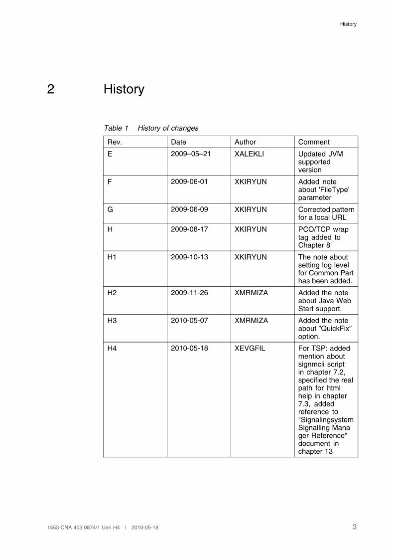
Table 1 History of changes
Rev. Date Author Comment
E 2009–05–21 XALEKLI Updated JVMsupportedversion
F 2009-06-01 XKIRYUN Added noteabout 'FileType'parameter
G 2009-06-09 XKIRYUN Corrected patternfor a local URL
H 2009-08-17 XKIRYUN PCO/TCP wraptag added toChapter 8
H1 2009-10-13 XKIRYUN The note aboutsetting log levelfor Common Parthas been added.
H2 2009-11-26 XMRMIZA Added the noteabout Java WebStart support.
H3 2010-05-07 XMRMIZA Added the noteabout ”QuickFix”option.
H4 2010-05-18 XEVGFIL For TSP: addedmention aboutsignmcli scriptin chapter 7.2,specified the realpath for htmlhelp in chapter7.3, addedreference to"SignalingsystemSignalling Manager Reference"document inchapter 13
31553-CNA 403 0874/1 Uen H4 | 2010-05-18

Signaling Manager User Guide
4 1553-CNA 403 0874/1 Uen H4 | 2010-05-18
Introduction
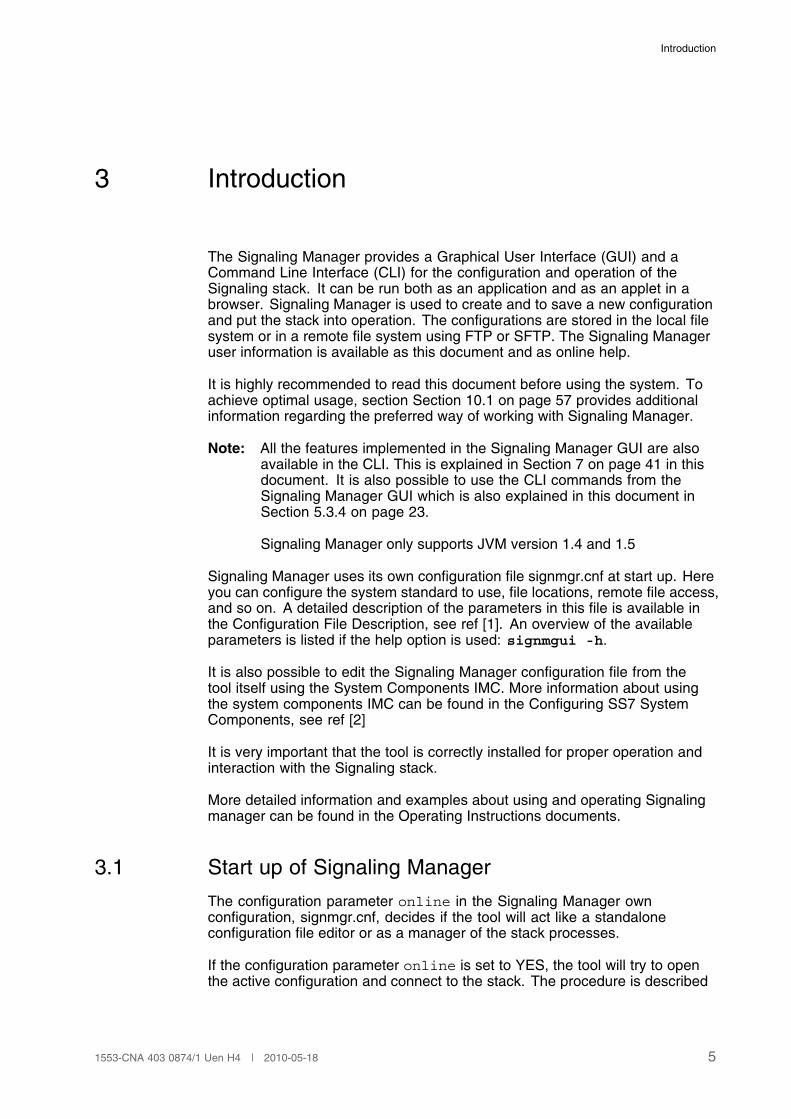
3 Introduction
The Signaling Manager provides a Graphical User Interface (GUI) and aCommand Line Interface (CLI) for the configuration and operation of theSignaling stack. It can be run both as an application and as an applet in abrowser. Signaling Manager is used to create and to save a new configurationand put the stack into operation. The configurations are stored in the local filesystem or in a remote file system using FTP or SFTP. The Signaling Manageruser information is available as this document and as online help.
It is highly recommended to read this document before using the system. Toachieve optimal usage, section Section 10.1 on page 57 provides additionalinformation regarding the preferred way of working with Signaling Manager.
Note: All the features implemented in the Signaling Manager GUI are alsoavailable in the CLI. This is explained in Section 7 on page 41 in thisdocument. It is also possible to use the CLI commands from theSignaling Manager GUI which is also explained in this document inSection 5.3.4 on page 23.
Signaling Manager only supports JVM version 1.4 and 1.5
Signaling Manager uses its own configuration file signmgr.cnf at start up. Hereyou can configure the system standard to use, file locations, remote file access,and so on. A detailed description of the parameters in this file is available inthe Configuration File Description, see ref [1]. An overview of the availableparameters is listed if the help option is used: signmgui -h.
It is also possible to edit the Signaling Manager configuration file from thetool itself using the System Components IMC. More information about usingthe system components IMC can be found in the Configuring SS7 SystemComponents, see ref [2]
It is very important that the tool is correctly installed for proper operation andinteraction with the Signaling stack.
More detailed information and examples about using and operating Signalingmanager can be found in the Operating Instructions documents.
3.1 Start up of Signaling Manager
The configuration parameter online in the Signaling Manager ownconfiguration, signmgr.cnf, decides if the tool will act like a standaloneconfiguration file editor or as a manager of the stack processes.
If the configuration parameter online is set to YES, the tool will try to openthe active configuration and connect to the stack. The procedure is described
51553-CNA 403 0874/1 Uen H4 | 2010-05-18
Signaling Manager User Guide
below. In this description the files planned.om.cim and active.om.cim ismentioned. Both files is of type .cim which is the file type that Signaling Manageruses to store the configuration. The definition of planned is a configuration thathas been saved but is not set on the current running stack. The active fileconsists of the configuration that the current running stack is using.
1. Searches for planned.om.cim file in the config location directoryspecified as config.location in the signmgr.cnf file and loads it if found.
2. If planned.om.cim is not found, it will search for active.om.cim in thesame directory and load it.
3. If either of the above files are found, Signaling Manager will try to establisha connection to the Signaling Stack. The name of the loaded file will beshown in the title bar.
4. If none of the above files are found, the ”New” dialogue will be displayedwithout trying to establish any connection to the stack.
If the configuration parameter online is set to NO, none of the above will bedone and a blank Signaling Manager will be opened. When operating in thismode it is not possible to connect to the stack.
Note: You may launch and start Signaling Manager from a web page. Thishas been supported by using the Java Web Start technology. It is alsopossible to run Signaling Manager as applet. For more informationsee ref [2].
3.2 Standards in Signaling Manager
The behavior of Signaling Manager is in several different aspects dependenton a standard setting. Example values are ITU or ANSI. The complete set ofvalues is found in Configuration File Description, see ref [1].
An overall system standard is set in Signaling Manager configuration includedin signmgr.cnf or as a command line option. However, elements on differentstack configuration levels such as network level, can be assigned specificstandards overriding the system standard. The default value is though areference to the system standard value.
If standard is not applicable on system level, for example in a gatewayconfiguration between networks of different standards, the standard insignmgr.cnf can be assigned a NA value. This value is applicable forsystem standard only, not for standard parameters on other configurationlevels. If system standard is set to NA, standard values must be set (possible inserveral places) on a more detailed configuration level to provide all parts of theconfiguration with a valid standard value.
Changing the value of any occurrence of standard will change the operatingconditions for Signaling Manager in the scope of the standard value. In somecases, the user interface is not affected, but in other cases the user is able tosee a difference apart from the actual standard value. For example, default
6 1553-CNA 403 0874/1 Uen H4 | 2010-05-18
Introduction
values might be changed as well as contents of various lists and descriptions.More specific changes to the behavior depending on standard are described incoming sections.
3.3 File Versions in Signaling Manager
For some modules, Signaling Manager has support for generation (export)of more than one CNF file version. When this is the case the appropriatefile version that correspond to the module version has been configured inthe settings for Signaling Manager. The properties or relations that are notapplicable to the selected file version is automatically hidden in the GUI and CLI.It is however not possible to hide information about these in the documentationthat is included with Signaling Manager, so if the documents mentions elementsthat are not visible then they are not applicable for your Signaling Stack.
3.4 Multi File System Support (MFS)
To be able to use Signaling Manager in an MFS environment the parameterrio.host.name in the Signaling Manager configuration file needs to be set tothe names of all used hosts. Hosts that should be used in an MFS environmenttogether with Signaling Manager needs to use the same port, protocol, installroot, username and password. If you specify the initial hostnames with help ofthe Signaling Manager IMC, you need to restart Signaling Manager for changesto apply. After starting Signaling Manager in MFS mode you can add, removeand temporary inactivate them in runtime. A host can temporary be inactivatedby prefix the hostname with a ‘‘!’’.
When you run Signaling Manager in MFS mode, write fileoperations are madeagainst all specified hosts, but read operations are made only from the firstspecified host. No automatic consistency check is made of the filesystem. Aftera change in the host list, like activating a host after it has been inactivatedor after adding a host, it is important to do a validation and (eventually) asynchronization of the filesystems to be sure they are consistent. A filesystemvalidation shall also be made if a file operation fails for some reason.
3.5 Alarm support
Signaling Manager will listen to incoming alarms from the stack processes.Which alarms Signaling Manager will listen to are set in OAM. More informationabout setting the alarm mask in OAM can be found in the Configuring SS7System Components, see ref [2]. Alarms are, except from being logged to theUI, also being logged to a file called “sm.alarm.log”. To turn this logging off,you can set alarm.log.quantity to 0 (zero) .
Note: Signaling Manager subscribes, by default, to all ECM alarms. Thesecan be enabled or disabled by setting the “Ecm Alarm Enabled”property in the Signaling Manager configuration. The stack does notneed to be restarted in order to activate this modification.
71553-CNA 403 0874/1 Uen H4 | 2010-05-18
Signaling Manager User Guide
3.6 Audit Log
Signaling Manager has the ability to log certain user operations to file. A logentry is consists of a time stamp, type of entry and specific information for thisentry. The following operations are logged:
• Orders. Both the request and response.
• Stack operations:
� New process added.
� Process removed.
� Process restarted.
� Stack restarted.
� Active ECM set.
Logging is executed if the parameter audit.log.quantity is set to anon-zero value, the value indicates how many log files which should be rotated.The parameter audit.log.size determines the max size of each log file. Toset the location for the log file the parameter audit.log.location is used.The parameters are found in Signaling Manager IMC.
3.7 Statistics
Performance statistics can be received using the Statistics tab. It works verysimilar to the Actions except that it receives performance statistics and alarmcounters for a module instead of an action result.
8 1553-CNA 403 0874/1 Uen H4 | 2010-05-18
Using Signaling Manager Help
4 Using Signaling Manager Help
4.1 Options in Help Menu
The Signaling Manager help menu contains general help options:
• Contents – Brings up the Signaling Manager help information including theinformation in this document in a Web browser.
• About Signaling Manager – Brings up release and license information forSignaling Manager.
4.2 Description Tab
A short description of a property, element, action, parameter or an MO, currentlyhaving focus, is displayed in the Description tab of the Information pane.A property gains focus when its input field in the Properties tab is selected.Elements and MOs gains focus when selected in the Navigation pane.
91553-CNA 403 0874/1 Uen H4 | 2010-05-18

Signaling Manager User Guide
10 1553-CNA 403 0874/1 Uen H4 | 2010-05-18
The User Interface
5 The User Interface
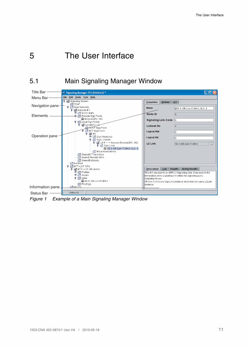
5.1 Main Signaling Manager Window
Menu Bar
Navigation pane
Elements
Operation pane
Information pane
Status Bar
Title Bar
Figure 1 Example of a Main Signaling Manager Window
111553-CNA 403 0874/1 Uen H4 | 2010-05-18
Signaling Manager User Guide
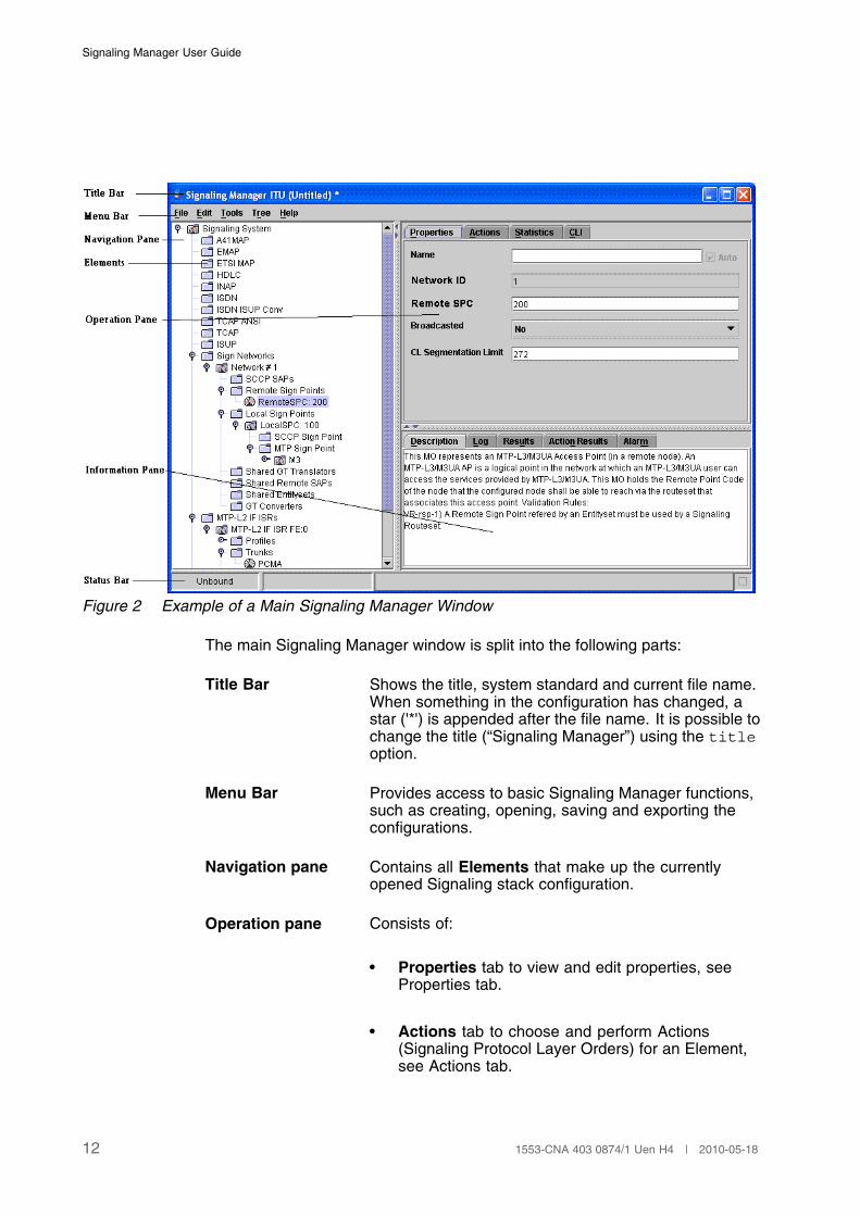
Figure 2 Example of a Main Signaling Manager Window
The main Signaling Manager window is split into the following parts:
Title Bar Shows the title, system standard and current file name.When something in the configuration has changed, astar ('*') is appended after the file name. It is possible tochange the title (“Signaling Manager”) using the titleoption.
Menu Bar Provides access to basic Signaling Manager functions,such as creating, opening, saving and exporting theconfigurations.
Navigation pane Contains all Elements that make up the currentlyopened Signaling stack configuration.
Operation pane Consists of:
• Properties tab to view and edit properties, seeProperties tab.
• Actions tab to choose and perform Actions(Signaling Protocol Layer Orders) for an Element,see Actions tab.
12 1553-CNA 403 0874/1 Uen H4 | 2010-05-18
The User Interface
• Statisticstab to choose and retrieve counters andstatistical information from the stack, see Statisticstab.
• CLI tab to perform MML commands, see CLI tab.
Information paneConsists of:
• Description tab for viewing the description of aselected property
• Log tab for logging information when debug isenabled
• Results tab for viewing the result of a validationor search
• Action Results for viewing the result of theperformed action
• Alarm for viewing current alarms and alarmnotifications
Status Bar Displays status information about stack connection andvarious process operations.
5.2 Signaling Manager Navigation Pane
The left hand side of the Signaling Manager main window contains the SignalingManager Navigation pane. It uses a tree like view to show the structure, asa set of Elements, of the Signaling System currently loaded into SignalingManager. The entire configuration of a Signaling Stack is performed by usingthe Navigation pane to add, delete and select Elements that make up thestack configuration.
In Signaling Manager, the Signaling System is a representation of the completeSignaling Stack. The elements in the tree represent the configuration of all theSignaling Protocol Layers. The required elements are added automaticallywhile the other must be added manually.
131553-CNA 403 0874/1 Uen H4 | 2010-05-18
Signaling Manager User Guide
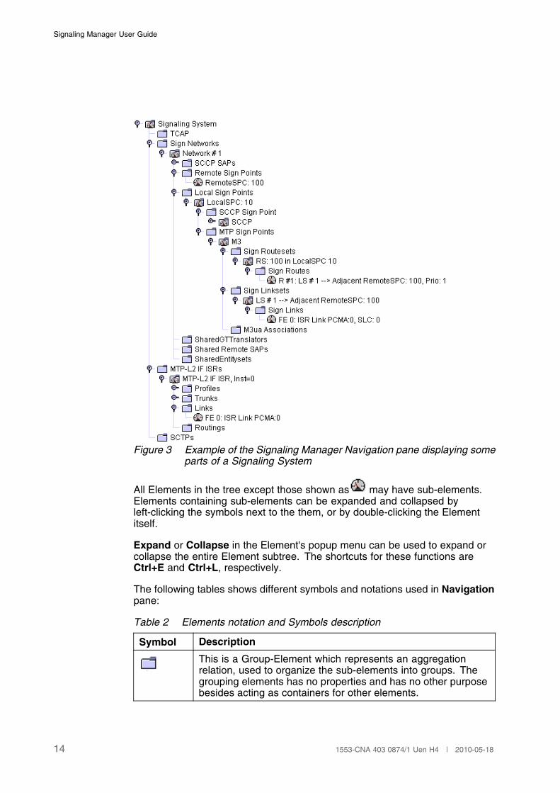
Figure 3 Example of the Signaling Manager Navigation pane displaying someparts of a Signaling System
All Elements in the tree except those shown as may have sub-elements.Elements containing sub-elements can be expanded and collapsed byleft-clicking the symbols next to the them, or by double-clicking the Elementitself.
Expand or Collapse in the Element's popup menu can be used to expand orcollapse the entire Element subtree. The shortcuts for these functions areCtrl+E and Ctrl+L, respectively.
The following tables shows different symbols and notations used in Navigationpane:
Table 2 Elements notation and Symbols description
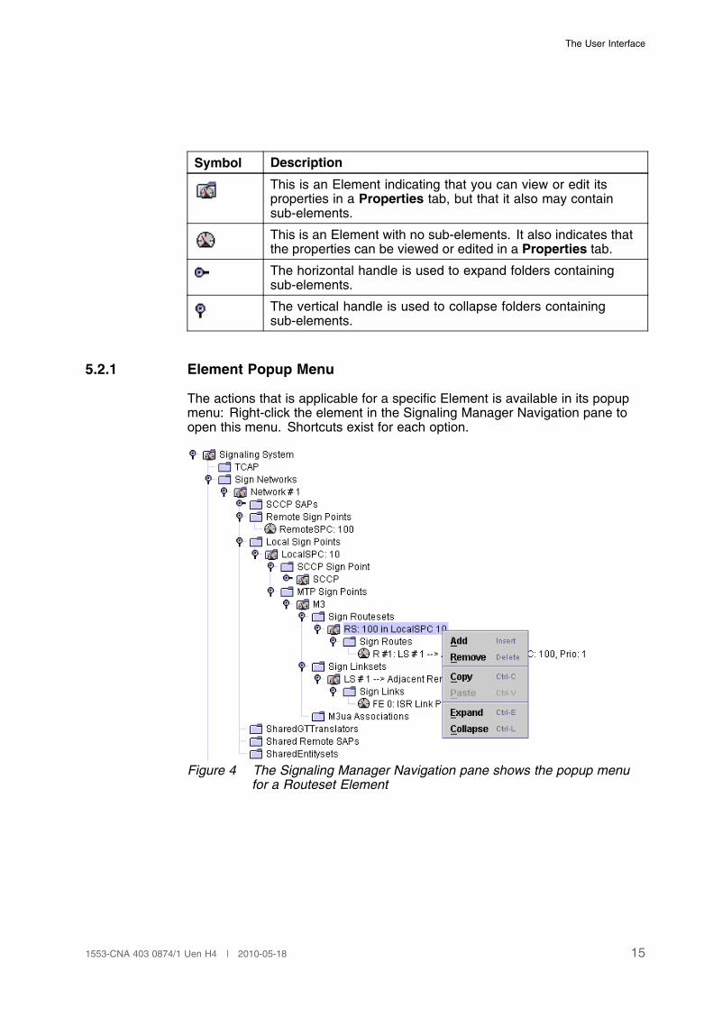
Symbol Description
This is a Group-Element which represents an aggregationrelation, used to organize the sub-elements into groups. Thegrouping elements has no properties and has no other purposebesides acting as containers for other elements.
14 1553-CNA 403 0874/1 Uen H4 | 2010-05-18
The User Interface
Symbol Description
This is an Element indicating that you can view or edit itsproperties in a Properties tab, but that it also may containsub-elements.
This is an Element with no sub-elements. It also indicates thatthe properties can be viewed or edited in a Properties tab.
The horizontal handle is used to expand folders containingsub-elements.
The vertical handle is used to collapse folders containingsub-elements.
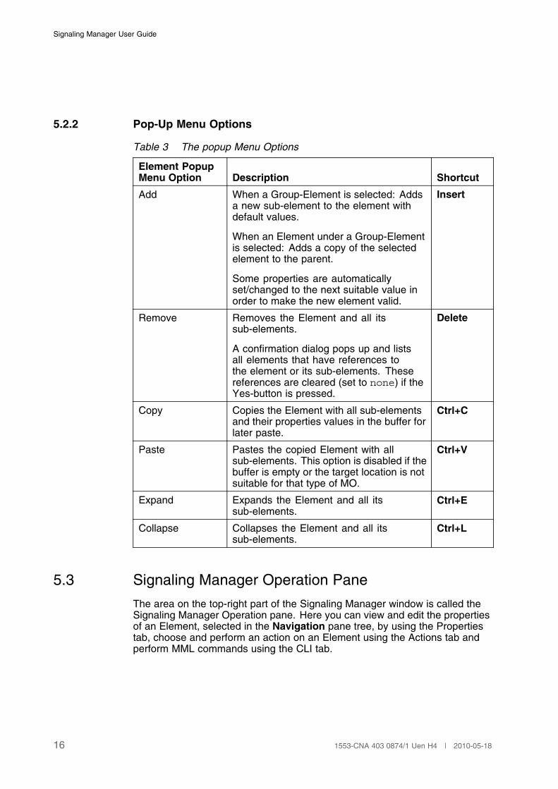
5.2.1 Element Popup Menu
The actions that is applicable for a specific Element is available in its popupmenu: Right-click the element in the Signaling Manager Navigation pane toopen this menu. Shortcuts exist for each option.
Figure 4 The Signaling Manager Navigation pane shows the popup menufor a Routeset Element
151553-CNA 403 0874/1 Uen H4 | 2010-05-18
Signaling Manager User Guide
5.2.2 Pop-Up Menu Options
Table 3 The popup Menu Options
Element PopupMenu Option Description Shortcut
Add When a Group-Element is selected: Addsa new sub-element to the element withdefault values.
When an Element under a Group-Elementis selected: Adds a copy of the selectedelement to the parent.
Some properties are automaticallyset/changed to the next suitable value inorder to make the new element valid.
Insert
Remove Removes the Element and all itssub-elements.
A confirmation dialog pops up and listsall elements that have references tothe element or its sub-elements. Thesereferences are cleared (set to none) if theYes-button is pressed.
Delete
Copy Copies the Element with all sub-elementsand their properties values in the buffer forlater paste.
Ctrl+C
Paste Pastes the copied Element with allsub-elements. This option is disabled if thebuffer is empty or the target location is notsuitable for that type of MO.
Ctrl+V
Expand Expands the Element and all itssub-elements.
Ctrl+E
Collapse Collapses the Element and all itssub-elements.
Ctrl+L
5.3 Signaling Manager Operation Pane
The area on the top-right part of the Signaling Manager window is called theSignaling Manager Operation pane. Here you can view and edit the propertiesof an Element, selected in the Navigation pane tree, by using the Propertiestab, choose and perform an action on an Element using the Actions tab andperform MML commands using the CLI tab.
16 1553-CNA 403 0874/1 Uen H4 | 2010-05-18
The User Interface
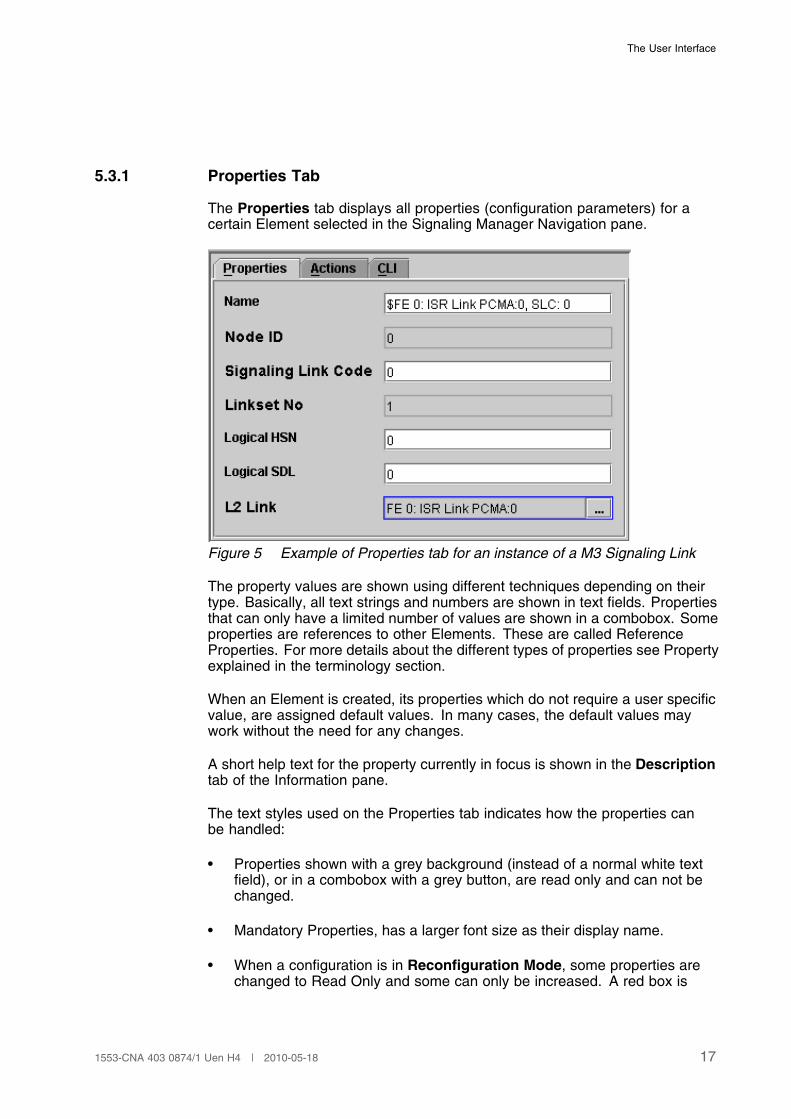
5.3.1 Properties Tab
The Properties tab displays all properties (configuration parameters) for acertain Element selected in the Signaling Manager Navigation pane.
Figure 5 Example of Properties tab for an instance of a M3 Signaling Link
The property values are shown using different techniques depending on theirtype. Basically, all text strings and numbers are shown in text fields. Propertiesthat can only have a limited number of values are shown in a combobox. Someproperties are references to other Elements. These are called ReferenceProperties. For more details about the different types of properties see Propertyexplained in the terminology section.
When an Element is created, its properties which do not require a user specificvalue, are assigned default values. In many cases, the default values maywork without the need for any changes.
A short help text for the property currently in focus is shown in the Descriptiontab of the Information pane.
The text styles used on the Properties tab indicates how the properties canbe handled:
• Properties shown with a grey background (instead of a normal white textfield), or in a combobox with a grey button, are read only and can not bechanged.
• Mandatory Properties, has a larger font size as their display name.
• When a configuration is in Reconfiguration Mode, some properties arechanged to Read Only and some can only be increased. A red box is
171553-CNA 403 0874/1 Uen H4 | 2010-05-18
Signaling Manager User Guide
drawn around the property input field to alert the user when it only canbe increased.
Note: Properties defined as expert are visible in the Properties tab if and onlyif the Expert Mode is activated from Tools menu
Note: Some properties are standard-dependent. If these properties have notbeen set and thus contain a default value, their value might changeupon changing the standard since different standards sometimes havedifferent default values. Aspects of standard for a specific property arealso displayed in the Description tab of the Information pane.
By default, the name property is empty and the checkbox to the right is marked.This default behavior gives the element an auto-generated name based on thevalues entered in the element. In order to give the element an own uniquename it is possible to edit the name field. This has the effect that this name isadded to the auto-generated name and they are shown in the GUI. To removethe autogenerated name uncheck the checkbox.
5.3.2 Actions Tab
The Actions tab displays all actions available for different Signaling ProtocolModules. In addition, a number of actions apply to the entire signaling system.
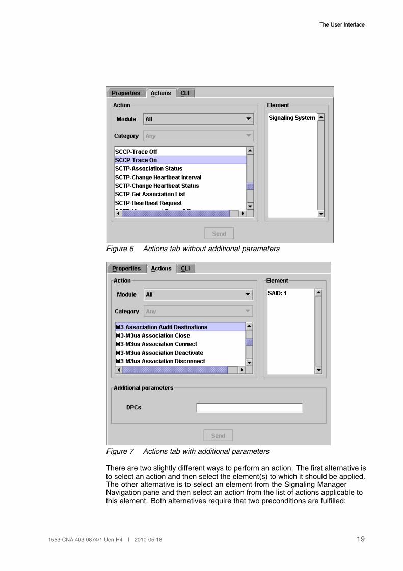
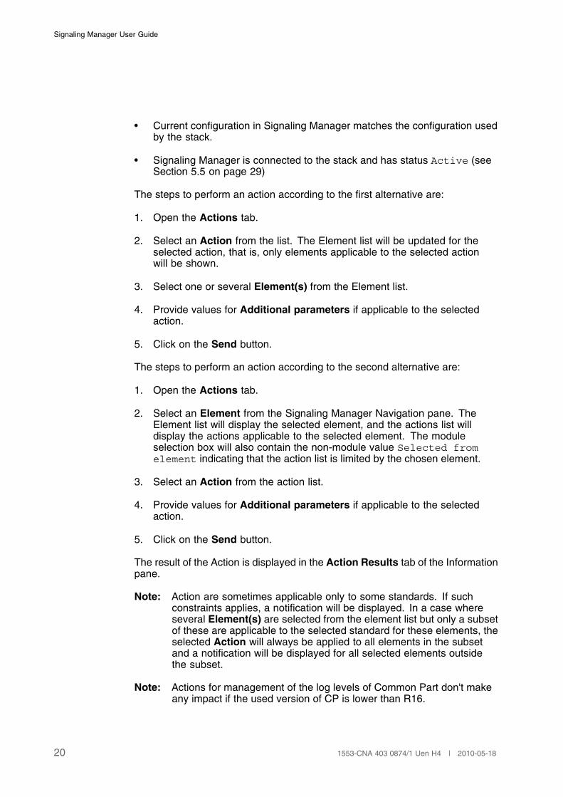
The tab consists of four parts: action area, element list, additional parametersand the Send button. From the Action area, the action is selected. The list ofactions can be limited by selecting a specific module. From the Element list,the element(s) to which the action is to be applied is selected. The visibility ofthe third part, the application parameters, depends on the action definition. Ifapplicable, this part is used for specifying additional action parameter valuesother than the ones defined by the selected element. Finally, the Send buttonperforms the action towards the stack.
Information about actions, additional parameters and possible standardconstraints are displayed in the Description tab of the Information pane whenan action or parameter is selected.
18 1553-CNA 403 0874/1 Uen H4 | 2010-05-18
The User Interface
Figure 6 Actions tab without additional parameters
Figure 7 Actions tab with additional parameters
There are two slightly different ways to perform an action. The first alternative isto select an action and then select the element(s) to which it should be applied.The other alternative is to select an element from the Signaling ManagerNavigation pane and then select an action from the list of actions applicable tothis element. Both alternatives require that two preconditions are fulfilled:
191553-CNA 403 0874/1 Uen H4 | 2010-05-18
Signaling Manager User Guide
• Current configuration in Signaling Manager matches the configuration usedby the stack.
• Signaling Manager is connected to the stack and has status Active (seeSection 5.5 on page 29)
The steps to perform an action according to the first alternative are:
1. Open the Actions tab.
2. Select an Action from the list. The Element list will be updated for theselected action, that is, only elements applicable to the selected actionwill be shown.
3. Select one or several Element(s) from the Element list.
4. Provide values for Additional parameters if applicable to the selectedaction.
5. Click on the Send button.
The steps to perform an action according to the second alternative are:
1. Open the Actions tab.
2. Select an Element from the Signaling Manager Navigation pane. TheElement list will display the selected element, and the actions list willdisplay the actions applicable to the selected element. The moduleselection box will also contain the non-module value Selected fromelement indicating that the action list is limited by the chosen element.
3. Select an Action from the action list.
4. Provide values for Additional parameters if applicable to the selectedaction.
5. Click on the Send button.
The result of the Action is displayed in the Action Results tab of the Informationpane.
Note: Action are sometimes applicable only to some standards. If suchconstraints applies, a notification will be displayed. In a case whereseveral Element(s) are selected from the element list but only a subsetof these are applicable to the selected standard for these elements, theselected Action will always be applied to all elements in the subsetand a notification will be displayed for all selected elements outsidethe subset.
Note: Actions for management of the log levels of Common Part don't makeany impact if the used version of CP is lower than R16.
20 1553-CNA 403 0874/1 Uen H4 | 2010-05-18
The User Interface
5.3.3 Statistics tab
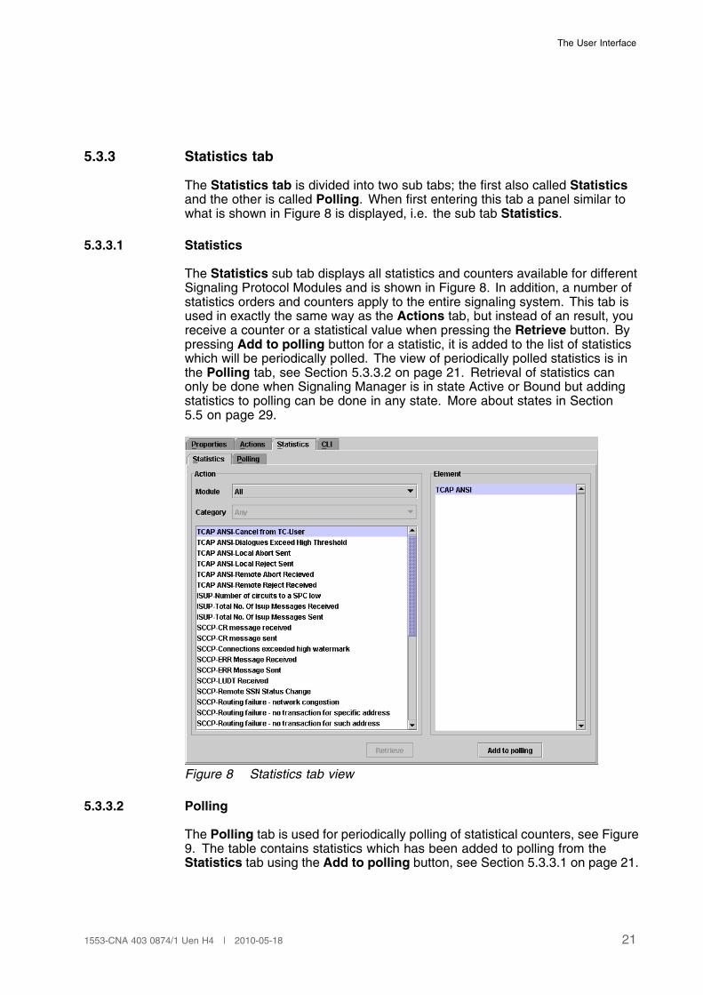
The Statistics tab is divided into two sub tabs; the first also called Statisticsand the other is called Polling. When first entering this tab a panel similar towhat is shown in Figure 8 is displayed, i.e. the sub tab Statistics.
5.3.3.1 Statistics
The Statistics sub tab displays all statistics and counters available for differentSignaling Protocol Modules and is shown in Figure 8. In addition, a number ofstatistics orders and counters apply to the entire signaling system. This tab isused in exactly the same way as the Actions tab, but instead of an result, youreceive a counter or a statistical value when pressing the Retrieve button. Bypressing Add to polling button for a statistic, it is added to the list of statisticswhich will be periodically polled. The view of periodically polled statistics is inthe Polling tab, see Section 5.3.3.2 on page 21. Retrieval of statistics canonly be done when Signaling Manager is in state Active or Bound but addingstatistics to polling can be done in any state. More about states in Section5.5 on page 29.
Figure 8 Statistics tab view
5.3.3.2 Polling
The Polling tab is used for periodically polling of statistical counters, see Figure9. The table contains statistics which has been added to polling from theStatistics tab using the Add to polling button, see Section 5.3.3.1 on page 21.
211553-CNA 403 0874/1 Uen H4 | 2010-05-18
Signaling Manager User Guide
Each row in the table shows both the counter value as well as the rate. Therate is calculate on the basis of how much the counter have been increasedper second during the last interval.
The polling interval and the last update is shown in the top of the panel.The polling interval can be changed in runtime through Signaling Managerconfiguration inside System Components, see ref [1]. Also note that the pollingis stopped when the interval is changed.
Pressing Start button, which is enabled in Active or Bound state, will startthe polling and the statistical counters will be updated periodically with thespecified interval. When the Start button has been pressed and the pollinghas started the button will change text to Stop and pressing it in this state willstop the polling.
Information about what statistic counters that are polled is included in the cimfile and are loaded when the cim file is opened. The polling will though neverbe active at startup and must be started manually to avoid that the system isloaded by a lot of statistic requests by mistake.
Note: Polling will be stopped automatically if state is changed from Activeor Bound, e.g. if disconnected.
If a row in the polling table is selected and then right-clicked a popup-menuappears with the possibility to remove the selected statistic from the set ofpolled statistics.
Note: If an element is removed from the tree in the navigation pane, allstatistics which depends on that instance will be removed from thepolling set.
22 1553-CNA 403 0874/1 Uen H4 | 2010-05-18

The User Interface
Figure 9 Polling tab view
5.3.4 CLI Tab
This tab displays a command field where you can type the Signaling Managercommands. The result of the commands is displayed in the area below theCommand field. Signaling Manager Navigation pane is also updated if thetyped command affects the tree structure.
Figure 10 CLI tab
In order to execute one of the available CLI commands within SignalingManager GUI, you may perform the following steps:
231553-CNA 403 0874/1 Uen H4 | 2010-05-18
Signaling Manager User Guide
1. Open the CLI tab
2. Type the specific command in the Command field using a syntax as<command>:<arg_1>=<value>,<arg_2>=<value>, where arg_n is anargument to the command.
Note: By typing help:cmd=<command> you can get detailed information fora command. See Notation and Features in Section 7 on page 41, toget more information on how a command can be performed. When CLIis used in Signaling Manager GUI, Ctrl+Space is used instead of Tabkey for completion feature explained in Section 7 on page 41.
A right-click in the Command field trigger a popup menu that consist of threealternatives: Clear, Abort and Load batch. Clear erases all earlier commandsfrom the history field below, Abort stops the current CLI-command, and Loadbatch starts a new batch job. It is important to use Load batch from thismenu because the CLI command “loadbatch” may not be executed from thecommand-line in the GUI.
5.3.5 System Overview tab
The system overview gives a table-based view of the objects in the configurationtree together with their status. The system overview is divided in categoriesand groups. Categories is visualized as tabs and groups as tables inside thecategories. Each row in a group table correspond to an element in the tree(MO Instance). Below is a list of all categories and their groups:
• Applications Server
� Local AS
� Remote AS
• Application Server Process
� Remote SGP
� Remote SP
• SSN
� Remote SSN
• Signaling Link
� Link
• Signaling Routeset
� Routeset
By default the system overview is disabled. It is enabled through theproperty System Overview Enabled in the Signaling Manger MO System
24 1553-CNA 403 0874/1 Uen H4 | 2010-05-18
The User Interface
Components->Signaling Manager. Inside the same MO the property SystemOverview Order Timer is located, which default value is set to 50. This timer isused to not overload the stack, it sets the number of milliseconds the SystemOverview should wait when sending orders to initially update all status fields.
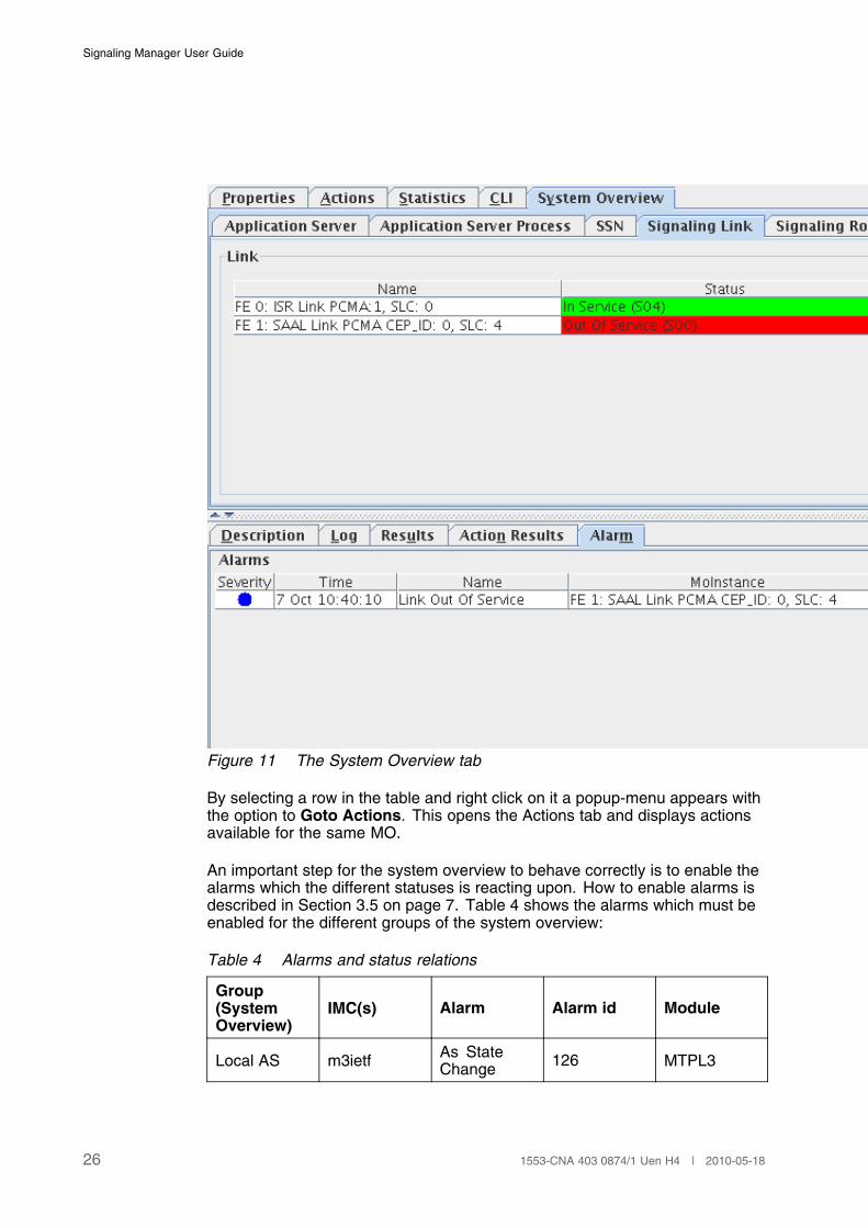
The status is updated using orders and alarms. Orders is used to retrieve theinitial status for all entries when Signaling Manager is started or when systemoverview is first enabled. The orders is used to update the status, e.g. an orderis received that a certain link is “Out of service” and the status for that particularlink is updated. When the alarm has ceased or been updated with anotherstatus the system overview will too. The status column for a MO can have threedifferent colors depending on the meaning of the status:
Green Everything is working fine.
Yellow Partially working.
Red Not working.
Consider the links in Figure 11, the one “In service” is green and the one “Outof service” is red, also note the active alarm which is informing about the linkout of service.
251553-CNA 403 0874/1 Uen H4 | 2010-05-18
Signaling Manager User Guide
Figure 11 The System Overview tab
By selecting a row in the table and right click on it a popup-menu appears withthe option to Goto Actions. This opens the Actions tab and displays actionsavailable for the same MO.
An important step for the system overview to behave correctly is to enable thealarms which the different statuses is reacting upon. How to enable alarms isdescribed in Section 3.5 on page 7. Table 4 shows the alarms which must beenabled for the different groups of the system overview:
Table 4 Alarms and status relations
Group(SystemOverview)
IMC(s) Alarm Alarm id Module
Local AS m3ietf As StateChange 126 MTPL3
26 1553-CNA 403 0874/1 Uen H4 | 2010-05-18
The User Interface
Remote AS m3ietf As StateChange 126 MTPL3
Remote SGP m3ietfSignalingProcessState Change
124 MTPL3
Remote SP m3ietfSignalingProcessState Change
124 MTPL3
Remote SSN sccpRemoteSSN StatusChange
42 SCCP
Link InService 3 MTPL3
Link m3ietfLink Out OfService 4 MTPL3
Route SetFailure 111 MTPL3
Routeset m3ietf, m3Route SetRecovery 112 MTPL3
If an alarm is not enabled the status related to that alarm will not be updated.This means that if only a subset of the statuses is interesting only the alarmsassociated to those need to be enabled, the rest will simply never get updated.
5.4 Signaling Manager Information Pane
The space on the bottom— right part of the Signaling Manager window is calledthe Signaling Manager Information pane.
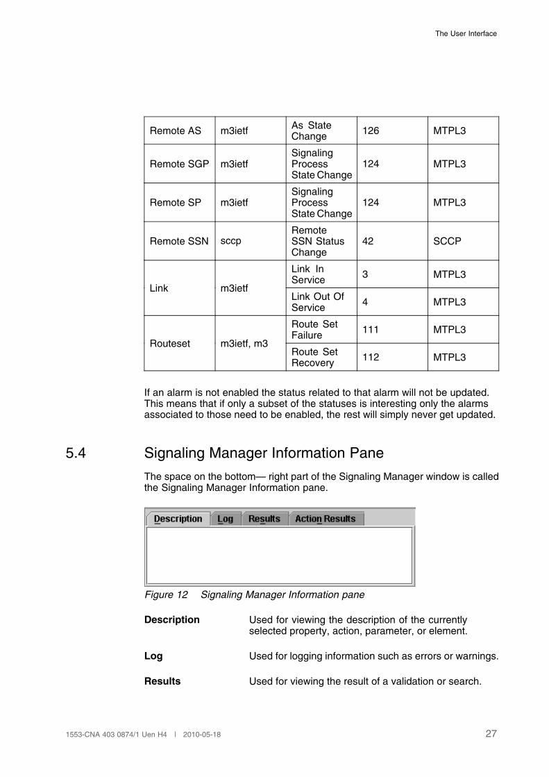
Figure 12 Signaling Manager Information pane
Description Used for viewing the description of the currentlyselected property, action, parameter, or element.
Log Used for logging information such as errors or warnings.
Results Used for viewing the result of a validation or search.
271553-CNA 403 0874/1 Uen H4 | 2010-05-18
Signaling Manager User Guide
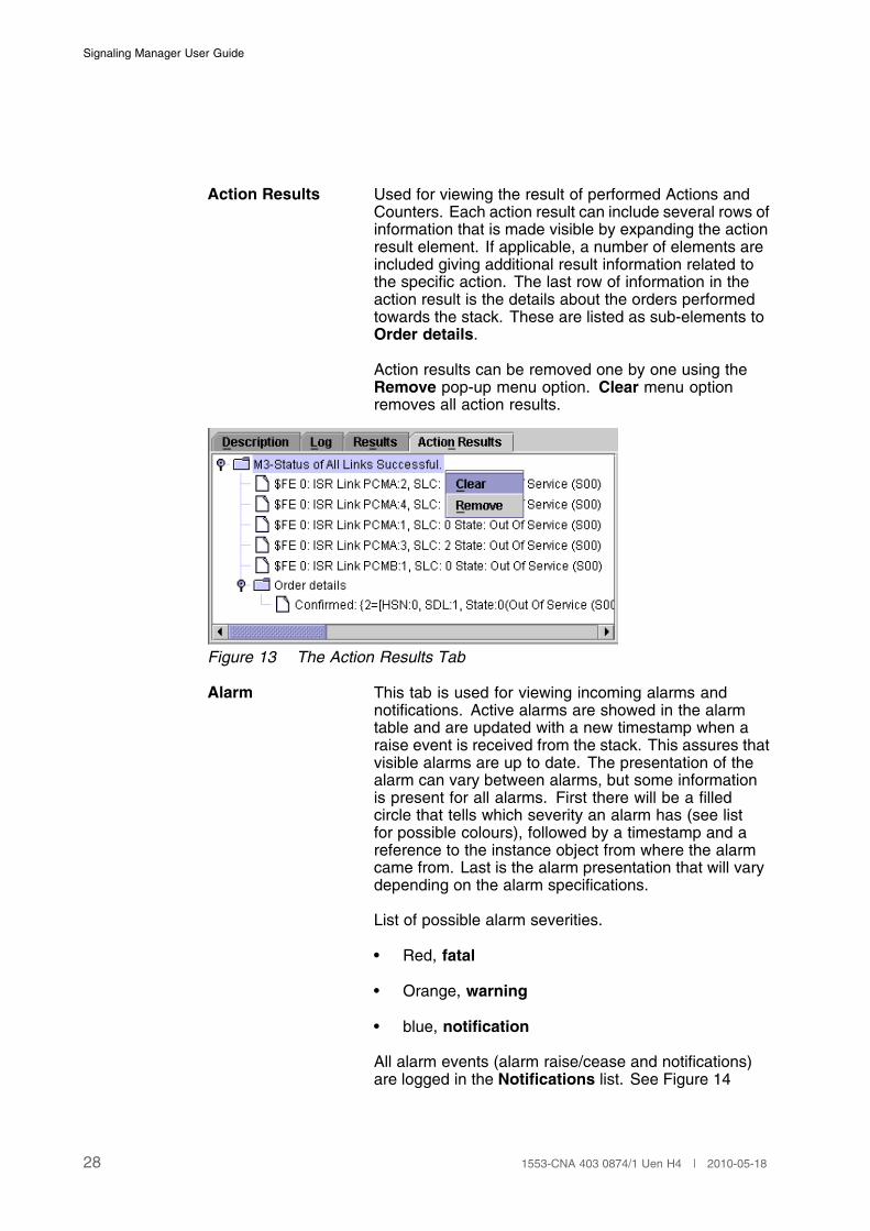
Action Results Used for viewing the result of performed Actions andCounters. Each action result can include several rows ofinformation that is made visible by expanding the actionresult element. If applicable, a number of elements areincluded giving additional result information related tothe specific action. The last row of information in theaction result is the details about the orders performedtowards the stack. These are listed as sub-elements toOrder details.
Action results can be removed one by one using theRemove pop-up menu option. Clear menu optionremoves all action results.
Figure 13 The Action Results Tab
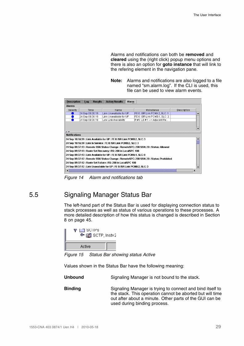
Alarm This tab is used for viewing incoming alarms andnotifications. Active alarms are showed in the alarmtable and are updated with a new timestamp when araise event is received from the stack. This assures thatvisible alarms are up to date. The presentation of thealarm can vary between alarms, but some informationis present for all alarms. First there will be a filledcircle that tells which severity an alarm has (see listfor possible colours), followed by a timestamp and areference to the instance object from where the alarmcame from. Last is the alarm presentation that will varydepending on the alarm specifications.
List of possible alarm severities.
• Red, fatal
• Orange, warning
• blue, notification
All alarm events (alarm raise/cease and notifications)are logged in the Notifications list. See Figure 14
28 1553-CNA 403 0874/1 Uen H4 | 2010-05-18
The User Interface
Alarms and notifications can both be removed andcleared using the (right click) popup menu options andthere is also an option for goto instance that will link tothe refering element in the navigation pane.
Note: Alarms and notifications are also logged to a filenamed “sm.alarm.log”. If the CLI is used, thisfile can be used to view alarm events.
Figure 14 Alarm and notifications tab
5.5 Signaling Manager Status Bar
The left-hand part of the Status Bar is used for displaying connection status tostack processes as well as status of various operations to these processes. Amore detailed description of how this status is changed is described in Section8 on page 45.
Figure 15 Status Bar showing status Active
Values shown in the Status Bar have the following meaning:
Unbound Signaling Manager is not bound to the stack.
Binding Signaling Manager is trying to connect and bind itself tothe stack. This operation cannot be aborted but will timeout after about a minute. Other parts of the GUI can beused during binding process.
291553-CNA 403 0874/1 Uen H4 | 2010-05-18
Signaling Manager User Guide
Bound Signaling Manager is connected and bound to the stackbut some stack processes are not in state Running.
Activating / ReactivatingSignaling Manager is activating the stack processeswith the configuration present in the stack file system.
Active All processes are in state Running.
Restarting SystemThe entire stack is restarted.
Restarting ProcessA single stack process is restarted.
Adding Process A new stack process is added.
Removing ProcessA stack process is removed.
Setting Active EcmThe stack is started on a new host.
5.6 Menu Bar
5.6.1 File Menu
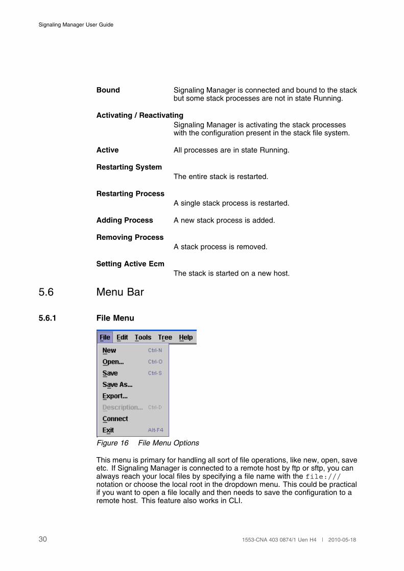
Figure 16 File Menu Options
This menu is primary for handling all sort of file operations, like new, open, saveetc. If Signaling Manager is connected to a remote host by ftp or sftp, you canalways reach your local files by specifying a file name with the file:///notation or choose the local root in the dropdown menu. This could be practicalif you want to open a file locally and then needs to save the configuration to aremote host. This feature also works in CLI.
30 1553-CNA 403 0874/1 Uen H4 | 2010-05-18
The User Interface
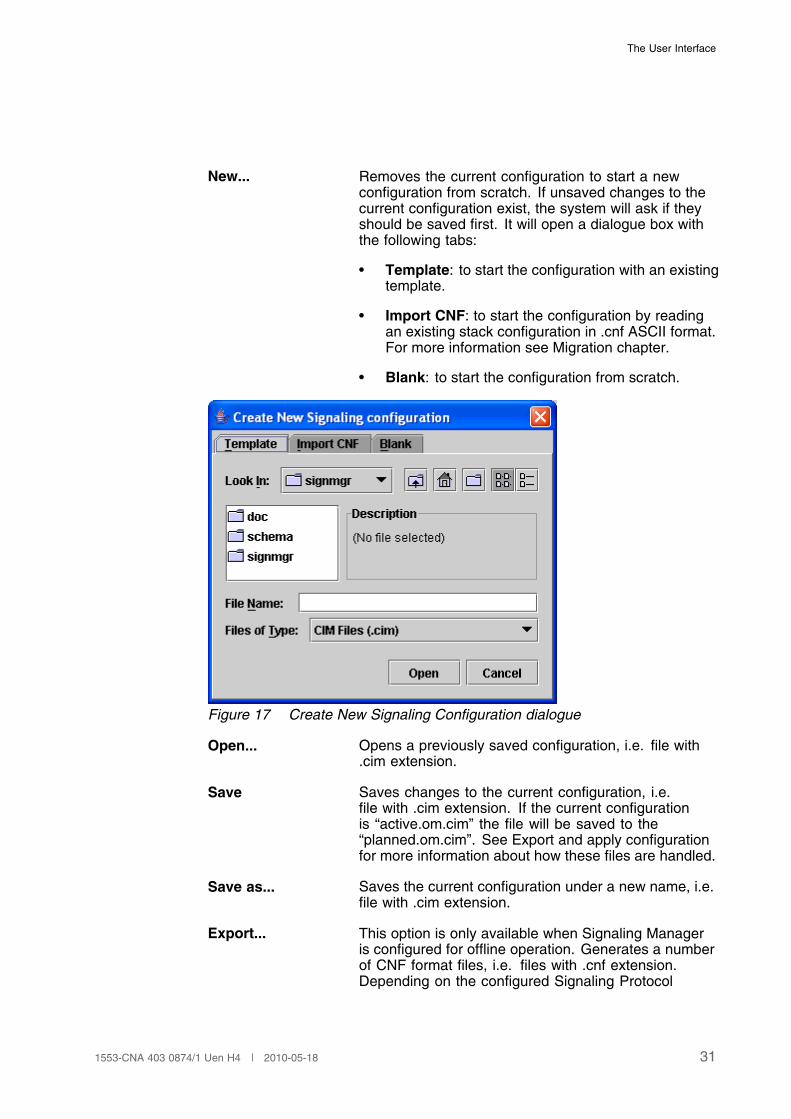
New... Removes the current configuration to start a newconfiguration from scratch. If unsaved changes to thecurrent configuration exist, the system will ask if theyshould be saved first. It will open a dialogue box withthe following tabs:
• Template: to start the configuration with an existingtemplate.
• Import CNF: to start the configuration by readingan existing stack configuration in .cnf ASCII format.For more information see Migration chapter.
• Blank: to start the configuration from scratch.
Figure 17 Create New Signaling Configuration dialogue
Open... Opens a previously saved configuration, i.e. file with.cim extension.
Save Saves changes to the current configuration, i.e.file with .cim extension. If the current configurationis “active.om.cim” the file will be saved to the“planned.om.cim”. See Export and apply configurationfor more information about how these files are handled.
Save as... Saves the current configuration under a new name, i.e.file with .cim extension.
Export... This option is only available when Signaling Manageris configured for offline operation. Generates a numberof CNF format files, i.e. files with .cnf extension.Depending on the configured Signaling Protocol
311553-CNA 403 0874/1 Uen H4 | 2010-05-18
Signaling Manager User Guide
Modules, one or more cnf files will be generated. Thisoption opens the Export dialogue box where you mayselect a directory to store all generated CNF files. CNFfiles are the files being used by the Signaling Protocolmodules during the initiation/reinitiation process.
Note: When using Signaling Manager online theConfigure button in the Process View is usedfor applying the configuration.
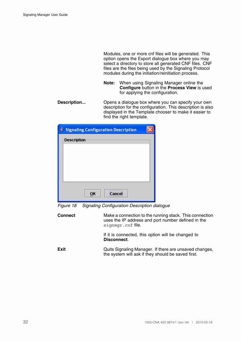
Description... Opens a dialogue box where you can specify your owndescription for the configuration. This description is alsodisplayed in the Template chooser to make it easier tofind the right template.
Figure 18 Signaling Configuration Description dialogue
Connect Make a connection to the running stack. This connectionuses the IP address and port number defined in thesignmgr.cnf file.
If it is connected, this option will be changed toDisconnect.
Exit Quits Signaling Manager. If there are unsaved changes,the system will ask if they should be saved first.
32 1553-CNA 403 0874/1 Uen H4 | 2010-05-18
The User Interface
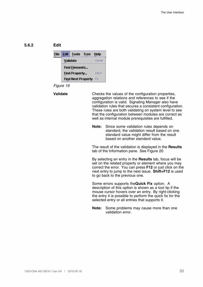
5.6.2 Edit
Figure 19
Validate Checks the values of the configuration properties,aggregation relations and references to see if theconfiguration is valid. Signaling Manager also havevalidation rules that secures a consistent configuration.These rules are both validating on system level to seethat the configuration between modules are correct aswell as internal module prerequisites are fulfilled.
Note: Since some validation rules depends onstandard, the validation result based on onestandard value might differ from the resultbased on another standard value.
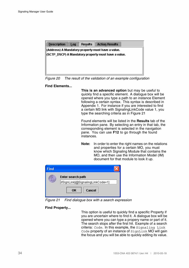
The result of the validation is displayed in the Resultstab of the Information pane. See Figure 20
By selecting an entry in the Results tab, focus will beset on the related property or element where you maycorrect the error. You can press F12 or just click on thenext entry to jump to the next issue. Shift+F12 is usedto go back to the previous one.
Some errors supports theQuick Fix option. Adescription of this option is shown as a tool tip if themouse cursor hovers over an entry. By right-clickingthe entry it is possible to perform the quick fix for theselected entry or all entries that supports it.
Note: Some problems may cause more than onevalidation error.
331553-CNA 403 0874/1 Uen H4 | 2010-05-18
Signaling Manager User Guide
Figure 20 The result of the validation of an example configuration
Find Elements...This is an advanced option but may be useful toquickly find a specific element. A dialogue box will beopened where you type a path to an instance Elementfollowing a certain syntax. This syntax is described inAppendix 1. For instance if you are interested to finda certain M3 link with SignalingLinkCode value 1, youtype the searching criteria as in Figure 21
Found elements will be listed in the Results tab of theInformation pane. By selecting an entry in that tab, thecorresponding element is selected in the navigationpane. You can use F12 to go through the foundinstances.
Note: In order to enter the right names on the relationsand properties for a certain MO, you mustknow which Signaling Module that contains theMO, and then use the Information Model (IM)document for that module to look it up.
Figure 21 Find dialogue box with a search expression
Find Property...This option is useful to quickly find a specific Property ifyou are uncertain where to find it. A dialogue box will beopened where you can type a propery name or part of it.The search stops after the first hit. Example of a searchcriteria: Code. In this example, the Signaling LinkCode property of an instance of SignLink MO will gainthe focus and you will be able to quickly editing its value.
34 1553-CNA 403 0874/1 Uen H4 | 2010-05-18
The User Interface
Find Next PropertyPress F3 or Find Next Property in the menu tojump to the next property that matches the searchcriteria. Example: Logical as search criteria willfind both Logical HSN and Logical SDL in theSignalingLink MO.
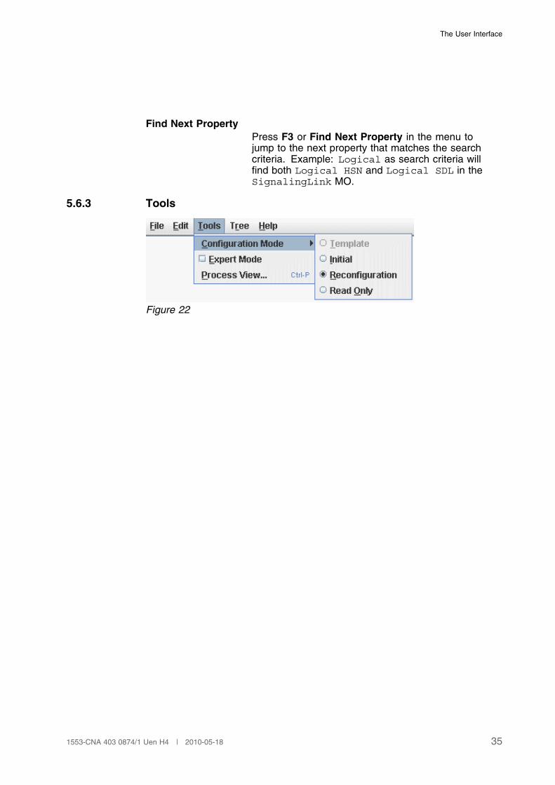
5.6.3 Tools
Figure 22
351553-CNA 403 0874/1 Uen H4 | 2010-05-18
Signaling Manager User Guide
Configuration ModeUsed to set the configuration in Initial, Reconfigurationor Read Only mode.
• Template: Turns off input field validation to allowany text to be entered as property value. Thisoption is only available when the Signaling Manageris in offline mode. The mode is useful for creatingtemplate configuration files. Property values, thatmust be defined before applying the configuration tothe stack, should be set to a text instruction aboutwhat value to fill in.
• Initial: Used when making changes that requiresthe stack to be restarted.
• Reconfiguration: Only the reconfigurableproperties are enabled for modification and therest are visible but disabled. Properties thatare configurable but may only be increased ordecreased, will be identified by an additional redbox around their input field. The “increase only”properties cannot be decreased from their currentvalue. If you accidently increase a value you mustchange to Initial mode to change it back, but only ifyou haven't configured the stack with the increasedvalue yet. The “decrease only” properties doesnot have any validation for them and it is up to theuser to keep in mind the previous value used bysignaling stack before any changes.
• Read Only: All the properties are locked forchanges. Useful when monitoring the stack usingActions, to avoid making changes by accident.
Note: Changing to or from Initial mode will bringup a dialog, warning about the possible risksassociated entering or leaving this mode;Changes to non-runtime reconfigurableproperties is allowed in Initial mode but arestart of the stack may be necessary for themto take effect.
Note: The Configuration Mode also controls thelock-file. When in Read Only mode no lock-fileis created, the other two modes require thata lock-file exists. See also the read.onlyparameter that controls whether to start asRead Only by default or not.
36 1553-CNA 403 0874/1 Uen H4 | 2010-05-18
The User Interface
Expert Mode To hide or view the expert properties for anymodification. Expert properties are properties whichnormally a regular user does not need to edit.
Process View Opens Signaling Stack Process View dialogue boxwhere you can perform various process handlingoperations. See Process Handling Section 8 on page45 for more details.
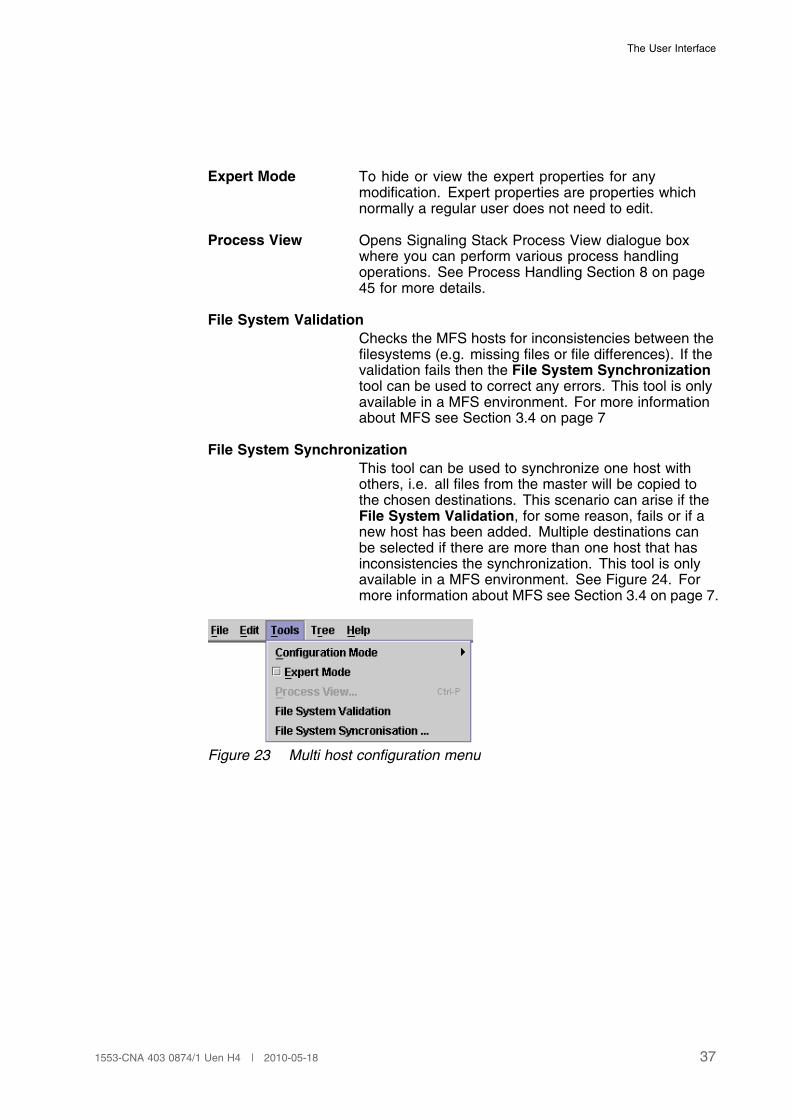
File System ValidationChecks the MFS hosts for inconsistencies between thefilesystems (e.g. missing files or file differences). If thevalidation fails then the File System Synchronizationtool can be used to correct any errors. This tool is onlyavailable in a MFS environment. For more informationabout MFS see Section 3.4 on page 7
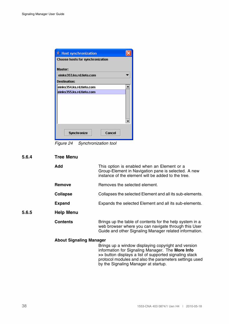
File System SynchronizationThis tool can be used to synchronize one host withothers, i.e. all files from the master will be copied tothe chosen destinations. This scenario can arise if theFile System Validation, for some reason, fails or if anew host has been added. Multiple destinations canbe selected if there are more than one host that hasinconsistencies the synchronization. This tool is onlyavailable in a MFS environment. See Figure 24. Formore information about MFS see Section 3.4 on page 7.
Figure 23 Multi host configuration menu
371553-CNA 403 0874/1 Uen H4 | 2010-05-18
Signaling Manager User Guide
Figure 24 Synchronization tool
5.6.4 Tree Menu
Add This option is enabled when an Element or aGroup-Element in Navigation pane is selected. A newinstance of the element will be added to the tree.
Remove Removes the selected element.
Collapse Collapses the selected Element and all its sub-elements.
Expand Expands the selected Element and all its sub-elements.
5.6.5 Help Menu
Contents Brings up the table of contents for the help system in aweb browser where you can navigate through this UserGuide and other Signaling Manager related information.
About Signaling ManagerBrings up a window displaying copyright and versioninformation for Signaling Manager. The More Info>> button displays a list of supported signaling stackprotocol modules and also the parameters settings usedby the Signaling Manager at startup.
38 1553-CNA 403 0874/1 Uen H4 | 2010-05-18
Shortcuts
6 Shortcuts
6.1 Alt - Mnemonic Options
Underlined Mnemonic characters is used to access functions without using themouse. The character is used as a short-cut together with the Alt key. Theseunderlined characters are visible in the labels in menus, tabs and buttons.Examples of these are:
• Alt+F: File
• Alt+F: File; Alt+E: File->Export...
• Alt+E: Edit
• Alt+E; Alt+E: Edit->Find Element...
• Alt+P, Alt+A, Alt+D. Alt+L, Alt+U, Alt+N, Alt-C, Alt-R: Used to swap betweenthe tabs of the Operation pane and the tabs of the Information pane.
Note: Mnemonic options are applicable only if the focus is in an appropriatecontext for the function.
6.2 Ctrl - Shortcuts Options
Some functions are available regardless where the focus is in SignalingManager. Ctrl key and the mnemonic character identified in the options in GUIare used for these functions. Example of some of these are:
• Ctrl+N: File->New...
• Ctrl+O: File->Open...
• Ctrl+S: File->Save
• Ctrl+D: File->Description...
• Ctrl+W: Edit->Validate
• Ctrl+F: Edit->Find Property...
• Ctrl+P: Tools->Process View...
One specially useful option is the “Rotate focus” shortcut (Ctrl+R) that movesfocus between the Signaling Manager Navigation pane and the Operation pane
391553-CNA 403 0874/1 Uen H4 | 2010-05-18
Signaling Manager User Guide
6.3 Function Keys (F1-F12)
The following Function Keys are used for specific purposes in SignalingManager:
F1 Help->Contents
F3 Edit->Find Next Property
F12 Selects the next result entry, displayed in the Resulttab of the Information pane.
Shift-F12 Selects the previous result entry.
6.4 Desktop Specific Keys
Arrows Used to navigate through the elements in the SignalingManager Navigation pane, or the properties in theProperties tab. It can also be used to navigate troughthe history in the CLI command field.
Ctrl+R Used to rotate the focus between the Signaling ManagerNavigation pane tree and the Operation pane.
Space Used to open the list of available options when aproperty using combobox or a reference property isselected in the Properties tab.
Page Up/Page DownUsed to scroll up and down the properties (fiveproperties at a hit) in the Properties tab.
40 1553-CNA 403 0874/1 Uen H4 | 2010-05-18
Command Line Interface (CLI)
7 Command Line Interface (CLI)
7.1 Overview
The CLI supports the same functionality as the Graphical User Interface. Ontop of providing a shell that accepts MML commands it is also possible to runthe tool in batch mode. In batch mode it reads a file containing a set of MMLcommands and executes them in the order they appear in the file.
All supported commands can be divided into three groups.
• Create and modify Configuration.
When configuring from the CLI, the same principle is used as from theGUI in terms of create and modify MO instances. For each MO in the treethere are create command, modify command, delete command and aprint command.
• Invoking Actions.
All actions are tied to a specific MO.
• Basic Signaling Manager functions.
Miscellaneous commands such as creating, importing, opening, savingand exporting the configurations.
Note: In order to be able to recognize the commands for a module, theystarts with the initials for that module. For example SS is the initial forSignaling System which is used for all commands defined for SignalingSystem, TC is used for TCAP, SC for SCCP, M3 for M3.
Note: When SM is started using CLI it is very important to load a proper .cimfile that contains the same configuration as is used in the running stack.If they mismatch you may get strange and misleading information frome.g. procp command. To do this, use one of the following ways:
• signmcli -om.file="file.name.cim"
• cli> open: file="file_name.cim"
7.2 Starting the CLI
The CLI is started using the signmcli script whether it shall be run in batchmode or in interactive mode. In order to start in batch mode, pipe the file withMML commands to the script.
Interactive mode: signmcli
411553-CNA 403 0874/1 Uen H4 | 2010-05-18
Signaling Manager User Guide
Batch mode: signmcli < <mml_file> or cat <mml_file> |signmcli, where <mml_file> is a file containing all the commands.
Note: It is also possible to load batch files from within the CLI using theloadbatch command.
signmcli script should be started on linux processor from the certain location:"/opt/SignallingManager/bin/signmcli".
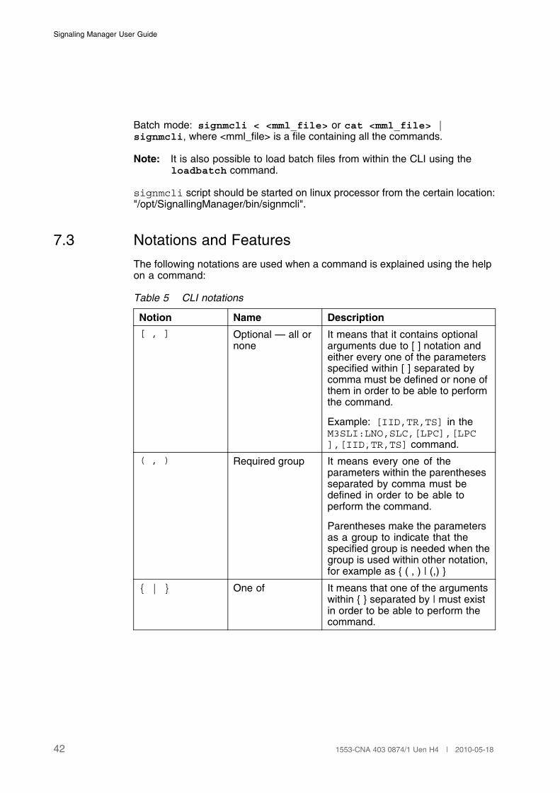
7.3 Notations and Features
The following notations are used when a command is explained using the helpon a command:
Table 5 CLI notations
Notion Name Description
[ , ] Optional — all ornone
It means that it contains optionalarguments due to [ ] notation andeither every one of the parametersspecified within [ ] separated bycomma must be defined or none ofthem in order to be able to performthe command.
Example: [IID,TR,TS] in theM3SLI:LNO,SLC,[LPC],[LPC],[IID,TR,TS] command.
( , ) Required group It means every one of theparameters within the parenthesesseparated by comma must bedefined in order to be able toperform the command.
Parentheses make the parametersas a group to indicate that thespecified group is needed when thegroup is used within other notation,for example as { ( , ) | (,) }
{ | } One of It means that one of the argumentswithin { } separated by | must existin order to be able to perform thecommand.
42 1553-CNA 403 0874/1 Uen H4 | 2010-05-18
Command Line Interface (CLI)
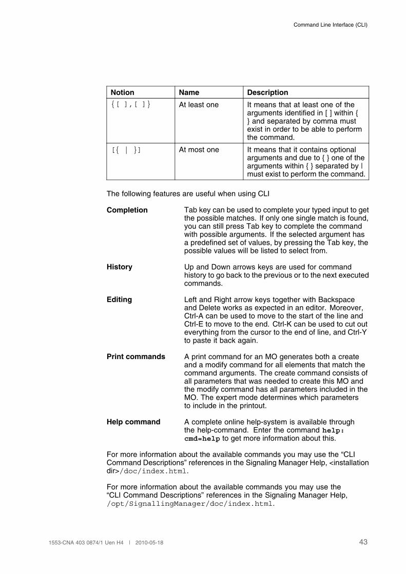
Notion Name Description
{[ ],[ ]} At least one It means that at least one of thearguments identified in [ ] within {} and separated by comma mustexist in order to be able to performthe command.
[{ | }] At most one It means that it contains optionalarguments and due to { } one of thearguments within { } separated by |must exist to perform the command.
The following features are useful when using CLI
Completion Tab key can be used to complete your typed input to getthe possible matches. If only one single match is found,you can still press Tab key to complete the commandwith possible arguments. If the selected argument hasa predefined set of values, by pressing the Tab key, thepossible values will be listed to select from.
History Up and Down arrows keys are used for commandhistory to go back to the previous or to the next executedcommands.
Editing Left and Right arrow keys together with Backspaceand Delete works as expected in an editor. Moreover,Ctrl-A can be used to move to the start of the line andCtrl-E to move to the end. Ctrl-K can be used to cut outeverything from the cursor to the end of line, and Ctrl-Yto paste it back again.
Print commands A print command for an MO generates both a createand a modify command for all elements that match thecommand arguments. The create command consists ofall parameters that was needed to create this MO andthe modify command has all parameters included in theMO. The expert mode determines which parametersto include in the printout.
Help command A complete online help-system is available throughthe help-command. Enter the command help:cmd=help to get more information about this.
For more information about the available commands you may use the “CLICommand Descriptions” references in the Signaling Manager Help, <installationdir>/doc/index.html.
For more information about the available commands you may use the“CLI Command Descriptions” references in the Signaling Manager Help,/opt/SignallingManager/doc/index.html.
431553-CNA 403 0874/1 Uen H4 | 2010-05-18
Signaling Manager User Guide
7.4 CLI Naming Conventions
The majority of Signaling Manager CLI commands consist of five characters,although exceptions from this rule exist when it comes to basic managementfunctions such as open and save configuration files. In order to understandthese five character commands, some general naming conventions apply.
• The first two characters reflects the module to which the command applies.
Examples: SS is the initial part of commands for Signaling System, TCAPcommands start with TC and SCCP commands start with SC.
• The last character reflect the operation. To achieve similarities with olderapplications related to Signaling Manager functionality, commands usedfor creating things ends with I (for initialize). The same reasons apply tomodify and delete operations. Modification commands ends with C (forchange) while delete operations ends with E (for end). Commands printinginformation generally ends with a P.
Examples:
TCAPI - creates a TCAP configuration
TCAPC - modifies an existing TCAP configuration
TCAPE - deletes an existing TCAP configuration
TCAPP - prints the current TCAP configuration
7.5 Standard Value in CLI
The standard value is used by the CLI to determine if a CLI command isapplicable or not. Applicable commands uses the standard value to determinethe set of parameters and their value ranges since some parameters and/orvalue ranges might not be applicable for a certain standard. If a CLI commandor command parameter is not applicable for the selected standard, an errormessage with the current standard constraints will be displayed.
The CLI on-line help will be given based on the system standard set insignmgr.cnf. If the system standard is set to value NA, descriptions will begiven for all standards, useful when running multi-standard configurations.
44 1553-CNA 403 0874/1 Uen H4 | 2010-05-18
Process Handling
8 Process Handling
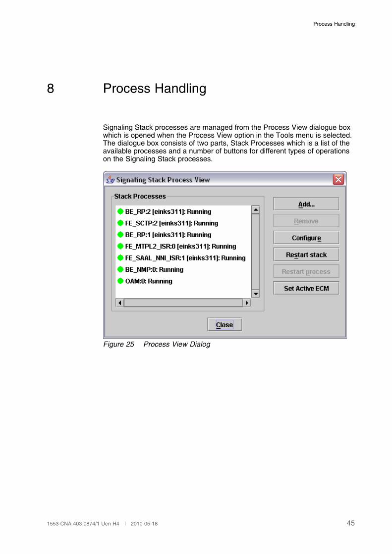
Signaling Stack processes are managed from the Process View dialogue boxwhich is opened when the Process View option in the Tools menu is selected.The dialogue box consists of two parts, Stack Processes which is a list of theavailable processes and a number of buttons for different types of operationson the Signaling Stack processes.
Figure 25 Process View Dialog
451553-CNA 403 0874/1 Uen H4 | 2010-05-18
Signaling Manager User Guide
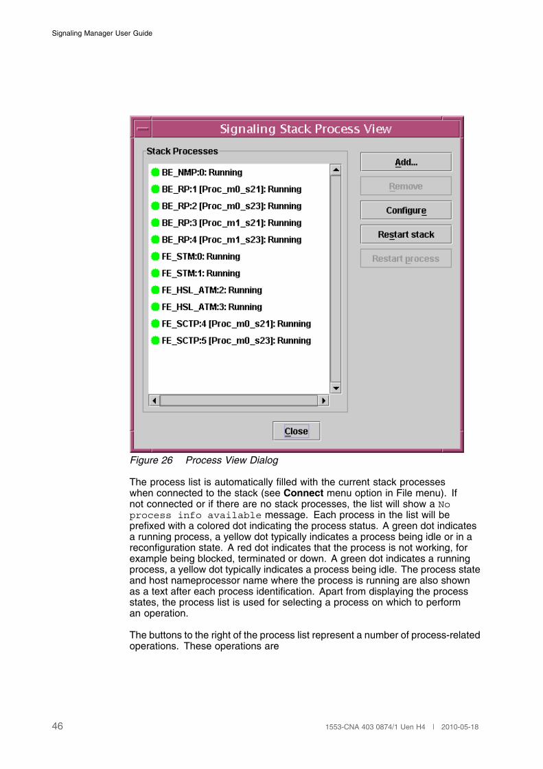
Figure 26 Process View Dialog
The process list is automatically filled with the current stack processeswhen connected to the stack (see Connect menu option in File menu). Ifnot connected or if there are no stack processes, the list will show a Noprocess info available message. Each process in the list will beprefixed with a colored dot indicating the process status. A green dot indicatesa running process, a yellow dot typically indicates a process being idle or in areconfiguration state. A red dot indicates that the process is not working, forexample being blocked, terminated or down. A green dot indicates a runningprocess, a yellow dot typically indicates a process being idle. The process stateand host nameprocessor name where the process is running are also shownas a text after each process identification. Apart from displaying the processstates, the process list is used for selecting a process on which to performan operation.
The buttons to the right of the process list represent a number of process-relatedoperations. These operations are
46 1553-CNA 403 0874/1 Uen H4 | 2010-05-18
Process Handling
Add... Adds a new BE or FE process to the system. SeeSection 8.1 on page 47 for details.
Remove Removes the selected BE or FE process from the setof running processes. See Section 8.2 on page 50 fordetails.
Configure Apply the configuration to the stack including allprocesses using the current configuration in SignalingManager. See Section 8.3 on page 50 for details.
Restart stack Stops and restarts all stack processes including ECMand automatically reconnects to the stack
Restart stack Stops and restarts all stack processes except forprocess monitoring PCF processes.
Note: The Restart stack operation will requirea manual connect to the restarted stackprocesses using Connect menu option in Filemenu.
Restart processStops and restarts the process selected in the processlist.
Set Active ECM Switch the host on which the active ECM, OAM andNMP processes are running. See Section 8.4 on page51 for details.
Note: The Set Active ECM operation will requirea manual connect to the restarted stackprocesses using Connect menu option in Filemenu.
All operations except for Configure requires that the application is in statusActive (see Section 5.5 on page 29 ). Remove and Restart Process alsorequire that a single process is selected in the process list.
8.1 Adding a Process
Adding a new process to the signaling system is done from a separate dialogdisplayed after pressing the Add... button.
471553-CNA 403 0874/1 Uen H4 | 2010-05-18

Signaling Manager User Guide
Figure 27 Add process dialogue box for a front end process
To add any new stack process, some pieces of information must be provided.Common to all new signaling processes are:
Host ID Name of the host ID on which the process shall start.The host must be predefined in the ecm.xml file.This file is located in the same directory as the stackconfiguration files. If the ECM IMC is loaded and usedfor configuring ECM, the Host ID is choosen from acombo box where the values are taken from the ECMconfiguration.
Start sequence groupName of a start sequence group also predefined in theecm.xml file. If the ECM IMC is loaded and used forconfiguring ECM, the Start sequnce group is choosenfrom a combo box where the values are taken from theECM configuration.
48 1553-CNA 403 0874/1 Uen H4 | 2010-05-18
Process Handling
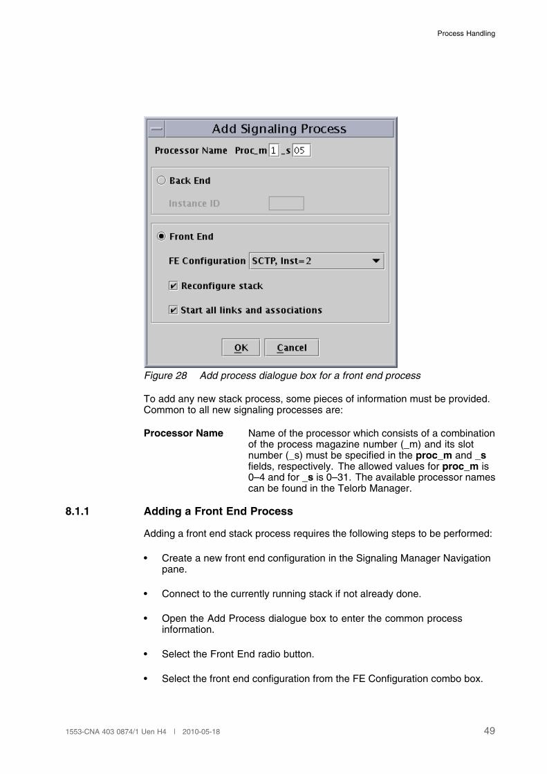
Figure 28 Add process dialogue box for a front end process
To add any new stack process, some pieces of information must be provided.Common to all new signaling processes are:
Processor Name Name of the processor which consists of a combinationof the process magazine number (_m) and its slotnumber (_s) must be specified in the proc_m and _sfields, respectively. The allowed values for proc_m is0–4 and for _s is 0–31. The available processor namescan be found in the Telorb Manager.
8.1.1 Adding a Front End Process
Adding a front end stack process requires the following steps to be performed:
• Create a new front end configuration in the Signaling Manager Navigationpane.
• Connect to the currently running stack if not already done.
• Open the Add Process dialogue box to enter the common processinformation.
• Select the Front End radio button.
• Select the front end configuration from the FE Configuration combo box.
491553-CNA 403 0874/1 Uen H4 | 2010-05-18
Signaling Manager User Guide
• Optionally uncheck the Reconfigure stack checkbox to avoid that theentire stack is reconfigured with the configuration currently present inSignaling Manager. Instead only the front end configuration used by thenew process will be exported and the new process started.
Note: It is important that a full reconfiguration is performed later tomake the configuration in Signaling Manager consistent with theconfiguration in the stack.
• Optionally uncheck the Start all links and associations checkbox if thelinks and associations shall be manually started later. For example afterthe new front end has been verified to work properly. This option is onlyavailable if the Reconfigure stack checkbox is checked.
• Press OK to add the new process.
8.1.2 Adding a Back End Process
Adding a back end stack process requires the following steps to be performed:
• Connect to the currently running stack if not already connected.
• Open the Add Process dialogue box to enter common process information.
• Select the Back End radio button.
• Possibly update the instance id. The first free id is suggested by SignalingManager.
• Press OK to add the new process.
8.2 Removing a Process
Removing a process is performed by selecting the process from the processlist and press the Remove button. The processes are neither reconfigured orrestarted as a consequence of this operation.
Note: It is strongly recommended to remove an FE from the configuration andthen verify before removing the process. If the configuration still isconsistent after the configuration changes, then remove the process.This is important to avoid traffic disturbances since links defined inBE processes usually is affected.
Note: It is not possible to remove the NMM process nor adding it.
8.3 Configuring a Stack
Pressing the Configure button will use the entire Signaling Managerconfiguration and generate new stack configuration files (cnf format) in thelocation where the stack processes reads their configuration information from.
50 1553-CNA 403 0874/1 Uen H4 | 2010-05-18
Process Handling
For details regarding the configuration file export, see Section 9 Export andApply Configuration on page 53.
8.4 Setting Active ECM
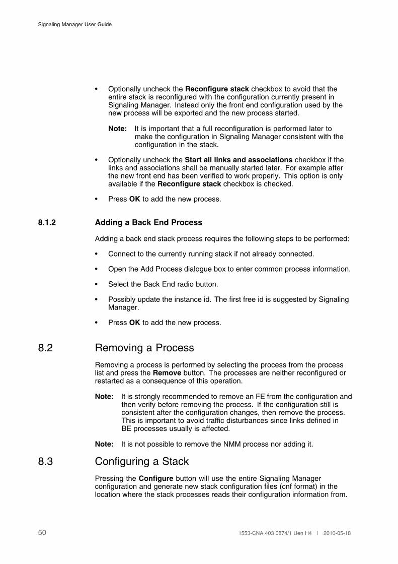
If the ECM and all stack processes must be moved to another host, the move isperformed by setting the active ECM host to another value.
Figure 29 Host ID dialogue used when setting new active ECM.
Setting a new host for ECM and stack processes requires the following stepsto be performed:
• Press the Set Active ECM button in Process View dialog to display theSet Active ECM dialog.
• Enter the name of the host on which the stack shall start.
• Press OK to perform the move.
All processes will now be terminated and new processes will be startedon the new host.
• Manually connect to the new stack using the Connect menu option inFile menu.
Note: To be able to connect to the stack on the new host, the IP addressmust be present in the list of CP Manager IP addresses in SignalingManager configuration file.
Note: Signaling Manager assumes that the old and new hosts use thesame file system location for configuration files. No implicit exportor reconfiguration operations are performed by Signaling Managerwhen setting a new active ECM.
511553-CNA 403 0874/1 Uen H4 | 2010-05-18

Signaling Manager User Guide
52 1553-CNA 403 0874/1 Uen H4 | 2010-05-18
Export and Apply Configuration
9 Export and Apply Configuration
This chapter describes how to apply the configuration changes in the SignalingManager to the stack processes.
9.1 Offline Configuration
The purpose of offline configuration is mainly for editing templates or preparingconfigurations for new installations. The tool behaves as a normal editor.Creating reconfigurations in this mode should be avoided, since this makes itharder for the tool to guarantee that the configuration updates are acceptedby the stack. It is not possible to apply a configuration to the stack while inthis mode.
To avoid that the stack configuration is changed by mistake, theexport.location directory is protected from use in offline mode. The onlypurpose of the Export menu item is for use by advanced users that want toreview the generated CNF-files.
Note: If you are using the CLI it is possible to do a initial configuration with thecommand: configure: INITIAL;
9.2 Online Configuration: Initial
An initial configuration of a stack is done when installing, upgrading or whenit is necessary to restart the stack processes for any other reason, like whenchanging properties that are not runtime reconfigurable. The configuration maybe prepared by using a predefined template, by importing it from the CNF-filesof a previous release or by creating it from scratch.
Note: After a configure is performed Signaling Manager automaticallychanges to Reconfig mode.
When performing an initial configuration, the Signaling Manager generates theconfiguration in CNF format (.cnf files) and puts it in the prespecified locationthat the stack has access to. The initial configuration requires the stack to bestarted or restarted to make the stack to load the configuration.
In order to apply the prepared configuration, perform the following steps:
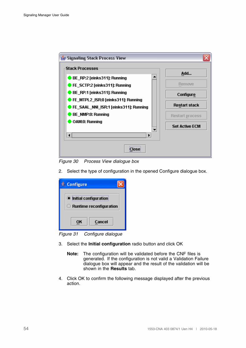
1. Click the Configure button in the Process View dialogue box.
531553-CNA 403 0874/1 Uen H4 | 2010-05-18
Signaling Manager User Guide
Figure 30 Process View dialogue box
2. Select the type of configuration in the opened Configure dialogue box.
Figure 31 Configure dialogue
3. Select the Initial configuration radio button and click OK
Note: The configuration will be validated before the CNF files isgenerated. If the configuration is not valid a Validation Failuredialogue box will appear and the result of the validation will beshown in the Results tab.
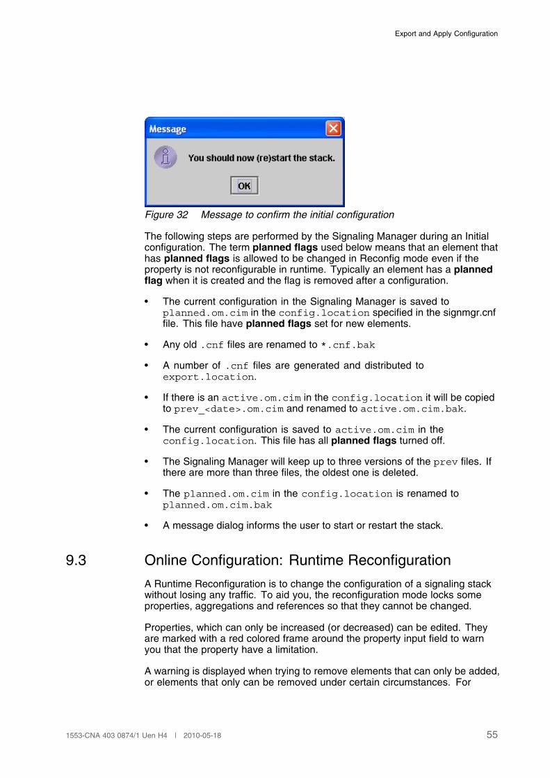
4. Click OK to confirm the following message displayed after the previousaction.
54 1553-CNA 403 0874/1 Uen H4 | 2010-05-18
Export and Apply Configuration
Figure 32 Message to confirm the initial configuration
The following steps are performed by the Signaling Manager during an Initialconfiguration. The term planned flags used below means that an element thathas planned flags is allowed to be changed in Reconfig mode even if theproperty is not reconfigurable in runtime. Typically an element has a plannedflag when it is created and the flag is removed after a configuration.
• The current configuration in the Signaling Manager is saved toplanned.om.cim in the config.location specified in the signmgr.cnffile. This file have planned flags set for new elements.
• Any old .cnf files are renamed to *.cnf.bak
• A number of .cnf files are generated and distributed toexport.location.
• If there is an active.om.cim in the config.location it will be copiedto prev_<date>.om.cim and renamed to active.om.cim.bak.
• The current configuration is saved to active.om.cim in theconfig.location. This file has all planned flags turned off.
• The Signaling Manager will keep up to three versions of the prev files. Ifthere are more than three files, the oldest one is deleted.
• The planned.om.cim in the config.location is renamed toplanned.om.cim.bak
• A message dialog informs the user to start or restart the stack.
9.3 Online Configuration: Runtime Reconfiguration
A Runtime Reconfiguration is to change the configuration of a signaling stackwithout losing any traffic. To aid you, the reconfiguration mode locks someproperties, aggregations and references so that they cannot be changed.
Properties, which can only be increased (or decreased) can be edited. Theyare marked with a red colored frame around the property input field to warnyou that the property have a limitation.
A warning is displayed when trying to remove elements that can only be added,or elements that only can be removed under certain circumstances. For
551553-CNA 403 0874/1 Uen H4 | 2010-05-18
Signaling Manager User Guide
instance in the case when you try to remove a Link which might be in use bythe running stack. A link can be removed but it must be stopped first.
Care must be taken to only use the configuration that is currently in use by thestack to do the changes. During normal online operation the right configurationis automatically loaded at startup. Unless open or new has been used it shouldbe OK to do the reconfiguration changes in runtime.
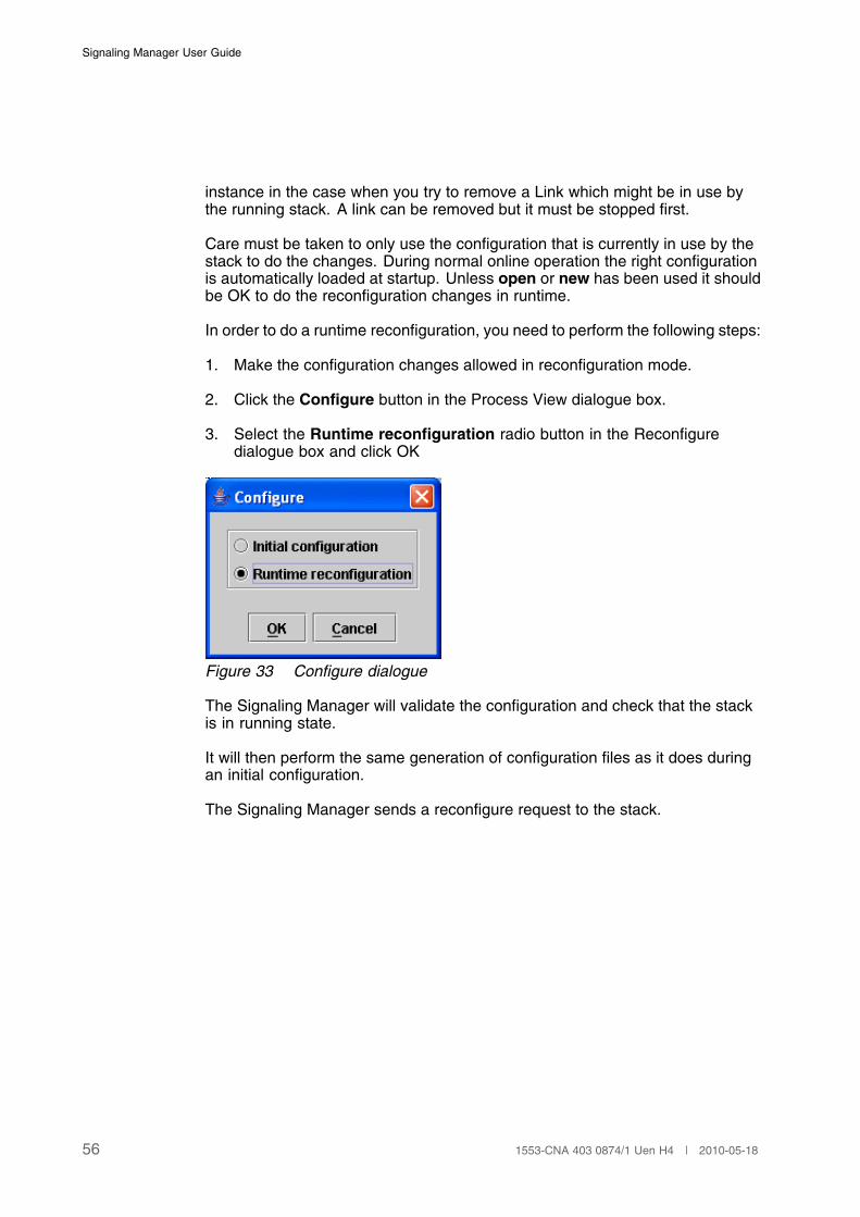
In order to do a runtime reconfiguration, you need to perform the following steps:
1. Make the configuration changes allowed in reconfiguration mode.
2. Click the Configure button in the Process View dialogue box.
3. Select the Runtime reconfiguration radio button in the Reconfiguredialogue box and click OK
Figure 33 Configure dialogue
The Signaling Manager will validate the configuration and check that the stackis in running state.
It will then perform the same generation of configuration files as it does duringan initial configuration.
The Signaling Manager sends a reconfigure request to the stack.
56 1553-CNA 403 0874/1 Uen H4 | 2010-05-18

Signaling Manager, General Operations
10 Signaling Manager, General Operations
10.1 Way of Working Recommendations
10.1.1 Introduction
A consequence of providing all necessary functions in Signaling Manager isthat some tasks can be performed in several different ways. Recommendationin this section selects the preferred way of working for each of these tasks.
10.1.2 Save Configuration in .cim File Format
It is recommended to use the .cim file format as the only format for storingstack configuration.
Although possible, it is not recommended to only save a configuration in.cnf format. This format is only used by the stack modules and has severaldrawbacks. For example, the information is stored in multiple files, loadingconfiguration into Signaling Manager requires several steps and migrationbecomes more difficult.
In the same way, it is not recommended to save configuration only as a filecontaining a set of CLI commands. If done, this makes validation of entireconfiguration hard and automatic migration is not supported.
10.1.3 Consider Automatic Naming
The automatic name of several elements reflects the configuration values forthe specific element. If the value of such an element is changed, the namechange accordingly. Therefore, always consider the automatic naming beforechanging to a specific name of an element. It is also possible to combinethese two labels. Select the alternative that provides most readability and iseasiest to understand.
10.2 Assign Reference
Means that an element is being selected and assigned to the current element.The procedure is:
1. Select an Element in Signaling Manager Navigation pane. Its propertieswill be listed in the Properties tab.
571553-CNA 403 0874/1 Uen H4 | 2010-05-18
Signaling Manager User Guide
2. Press Space key or click on the ... button for a Reference Property in theProperties tab of the selected Element in order to open the Select dialoguebox.
3. Select an element from the list of valid elements presented in the Selectdialogue box, if there is any, otherwise you need to add the requiredelements before being able to proceed.
4. Click on the OK button. The input field for the reference property in theProperties tab will be updated with the name of the referenced element.
Note: For some Reference Properties the cardinality is one to many. In thiscase it is possible to assign several elements to the same property.This is achieved by keeping the Ctrl button pressed while selectingthe desired elements. For a Reference Property that has one to onecardinality it is only possible to choose one element and in that casethe Ctrl button can not be used.
10.3 Add Element
Means that an element of a certain MO will be added to a Group-Element inthe Signaling Manager. You may make a copy of an existing Element or add anew Element using its default settings.
Note: It is recommended to use the copy variant described below, in order touse automation values for some properties.
10.3.1 Using Copy
The procedure for making a copy of an existing Element is:
1. Select an existing Element in Signaling Manager Navigation pane.
2. Press Insert key or Right-Click the Element to open its popup menuand select Add. A copy of the selected Element will be added to theGroup-Element containing that Element in Signaling Manager Navigation.
Some of the properties in the copy may have been automatically changed. Thisis done for properties that must be changed to make a valid configuration andwhere an automated change is likely to be correct.
10.3.2 Using New
The procedure for making a new Element is:
1. Select an Group-Element in Signaling Manager Navigation tree.
2. Press Insert key or Right-Click the Group-Element to open its popup menuand select Add. An instance of an MO will be added to the Group-Elementin Signaling Manager Navigation.
58 1553-CNA 403 0874/1 Uen H4 | 2010-05-18
Migration
11 Migration
11.1 Supported Modules
Signaling Manager supports a number of versions of the signaling stackprotocol modules. These can be viewed by selecting the More Info>> button inthe About Signaling Manager dialogue box.
11.2 Import CNF
11.2.1 General
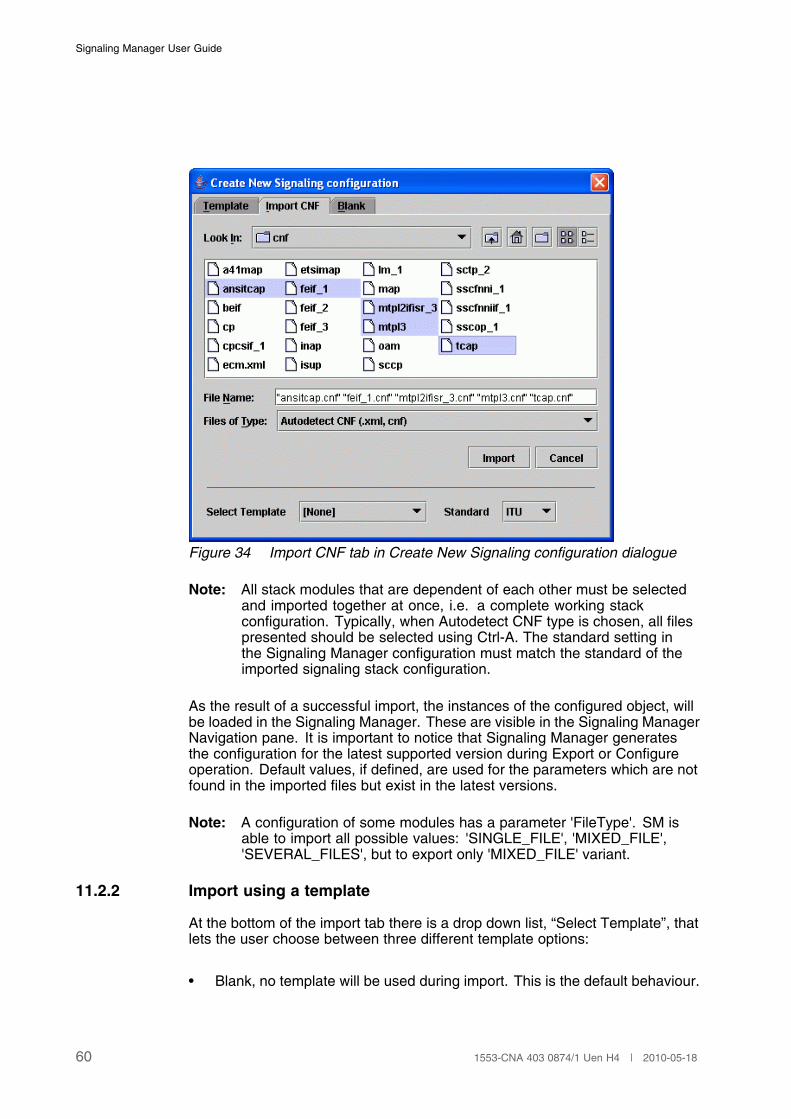
Signaling Manager provides the possibility to import an existing stackconfiguration in cnf format. This is done in the Import CNF tab from the New...menu. Signaling Manager automatically detects what module version the cnffiles is configured for and if the version is older than the current version it ismigrated to fit this format. This also implies that when configuring the stack orexporting the stack configuration the .cnf files will always be in the format ofthe current version for that module. The “Files of Type..” option shall be set toAutodetect CNF in order to filter so only supported cnf files are visible.
If you are importing an non HD configuration the cp.cnf should not beimported. For more information about how to configure CP in SignalingManager can be found in Configuring SS7 System Components, see ref [2].
When importing the “EINSS7_ECMclasses.xml” configuration file it will berenamed to “EINSS7_ECMclasses.xml.old” because it should not be usedanymore after the import is performed. When exporting the configuration theinformation in this file will be included in the “ecm.xml” file.
Note: It is possible to export a configuration in an older module version formatby setting the module.versions parameter. For more informationabout this see Section 3.3 on page 7
591553-CNA 403 0874/1 Uen H4 | 2010-05-18
Signaling Manager User Guide
Figure 34 Import CNF tab in Create New Signaling configuration dialogue
Note: All stack modules that are dependent of each other must be selectedand imported together at once, i.e. a complete working stackconfiguration. Typically, when Autodetect CNF type is chosen, all filespresented should be selected using Ctrl-A. The standard setting inthe Signaling Manager configuration must match the standard of theimported signaling stack configuration.
As the result of a successful import, the instances of the configured object, willbe loaded in the Signaling Manager. These are visible in the Signaling ManagerNavigation pane. It is important to notice that Signaling Manager generatesthe configuration for the latest supported version during Export or Configureoperation. Default values, if defined, are used for the parameters which are notfound in the imported files but exist in the latest versions.
Note: A configuration of some modules has a parameter 'FileType'. SM isable to import all possible values: 'SINGLE_FILE', 'MIXED_FILE','SEVERAL_FILES', but to export only 'MIXED_FILE' variant.
11.2.2 Import using a template
At the bottom of the import tab there is a drop down list, “Select Template”, thatlets the user choose between three different template options:
• Blank, no template will be used during import. This is the default behaviour.
60 1553-CNA 403 0874/1 Uen H4 | 2010-05-18
Migration
• Keep current model. Selecting this option assumes that a configuration isalready loaded. If Signaling Manager is run in online mode the configurationloaded will probably be an active.om.cim. The modules chosen to beimported from cnf will be “added” to the existing configuration as opposedto the default import scenario where any previous configuration is cleared.
• The third and last option is to select a specific template file from the oneslisted in the drop down list. All CIM files that exists in the template directorywill be listed here. The chosen template will be loaded prior to importingthe selected cnf files.
Note: If a module chosen to be imported already has been loaded by thetemplate file it will be discarded, no duplicates will be imported. Thelog for Signaling Manager will show each such duplicate found asa warning.
11.2.3 Standard Dependency during Import
When importing older cnf files that do not include standard information, thesystem standard set in signmgr.cnf will be used to select proper parse andvalidation rules. If a file cannot be properly parsed using this standard (becauseit was written/generated for a different standard), an error will be displayed andthe file will not be imported.
Note: Since system standard is used as fallback standard, value NA is not avalid value for system standard during import.
11.3 Migrating .cim Files
Signaling Manager supports opening of .cim files generated by olderSignaling Manager versions. Differences might occur between versions dueto parameters being added or removed, parameters becoming mandatory orparameters being moved from one configured object to another. Normally, themigration is made automatically and silent but the log will indicate that migrationhas been performed. However, effects of a migrated .cim file might be seen inone or several of the following ways depending on the reason for migration:
• Properties occur in the properties set of a different element than in theolder version.
• Validation fails because an added mandatory property without default valuehas not been set.
• The resulting .cnf files differ from the files generated by the older version.
Saving a converted .cim file is always done in the new format.
Note: Signaling Manager supports migration of complete and valid CIM filesonly.
611553-CNA 403 0874/1 Uen H4 | 2010-05-18

Signaling Manager User Guide
11.4 Migrating CLI Commands
11.4.1 General
There is no automatic migration function for CLI commands. If deviations aredetected, these must be adjusted manually by editing the file containing thecommand set.
Differences in parameters between different Signaling Manager versions forreasons described in Section 11.3 on page 61 also affect the CLI if the modifiedparameters are used in any CLI command. Thus, batch files containing setsof CLI commands must be migrated to reflect the new parameter set for eachaffected command.
If a single CLI command does not fulfill the new required syntax, an errormessage will be returned and the command will not be executed. In caseseveral commands are run in a batch, the entire set of commands will beanalyzed for migration changes prior to execution of the first command. Thisis to avoid inconsistency caused by failed commands late in the commandsequence.
11.4.2 Command Analyzer
To be able to verify the syntax of old files containing sets of CLI commandswhen migrating from one Signaling Manager version to another, the CLICommand Analyzer can be invoked without actually executing the commands.If there are deviations, the output is a list of all deviations in the provided set ofcommands.
The Command Analyzer is invoked separately by starting the CLI with theconfiguration parameters online=NO and batch.analysis=YES. SeeConfiguration File Description (ref [1]) for configuration parameter details.
A single command set file is analyzed by running the CLI in batch mode. Ifseveral files are to be tested or if the environment puts restrictions on commandline options and redirection, an alternative is to start the CLI once in interactivemode and execute the loadbatch CLI command for each file. Starting the CLIin different modes is described in Section 7.2 on page 41.
62 1553-CNA 403 0874/1 Uen H4 | 2010-05-18
Signaling Manager, Terms and Abbreviations
12 Signaling Manager, Terms andAbbreviations
12.1 Combobox
A combobox list is used for selecting a value in a list of available values. Itlooks like a button with a small triangular arrow on the right hand side. Click it,and a list showing the allowed values pops up. Select value, and the list closesagain. The Space key can be used to drop down the list when the comboboxfield is selected.
12.2 Editable Combobox
This works as a Combobox with the difference that the user is free to add a newvalue instead of choosing one of the predefined.
12.3 Radio Button
A radio button is a circular on or off button with a text describing the state to theright. Click the circle to make the radio button selected.
Radio buttons always appear in groups of two or more. Selecting one radiobutton automatically deselects the others in that group.
12.4 Checkbox
A checkbox is a square on or off button with a text describing the on state to theright. Click the box once to put it in the selected state (a checkmark appears inthe box). Clicking a second time deselects the checkbox again.
Checkboxes are always independent of one another. Checking one box doesnot affect the state of any other. Although selecting a checkbox may enableother buttons, text fields, and so on, that are only relevant when the checkboxis selected.
12.5 Input Text Field
This is used for typing a value for a property in its Properties tab. Someproperties are using default values but they can be modified within their rangewhich is displayed in the Description field of the Information pane. If you havechanged a default value, you may reset to the default value by just removingall the types value and press Enter.
631553-CNA 403 0874/1 Uen H4 | 2010-05-18
Signaling Manager User Guide
12.6 Disabled Field
Some properties depend on the value on some other properties. In this case,the properties, which are not valid during certain circumstances, are disabled.I.e. the input field are locked from any changes and grayed out.
12.7 Read Only Field
If a property is not allowed to be modified it will be shown as a Disabled Fieldin the Properties tab. Some properties are Read Only by default and somedepend on the Configuration Mode.
12.8 Element
A Signaling Manager element is any object that appears in the SignalingManager navigation tree view, i.e. a component providing a part of a signalingstack configuration. It is an instance of a certain MO in the Signaling ManagerNavigation pane. There are two types of elements:
Elements which can contain other elements, i.e. anelement with aggregation relation.
Elements which can not contain any other element assub-element, i.e. an element without any aggregationrelation.
Note: See also Group Element.
12.9 Group-Element
A special Signaling Manager element with no properties.It can only hold other Element of the same type. It isa notation for an aggregation relation in the SignalingManager navigation tree.
12.10 Sub-Element
An element appearing beneath another element in the Signaling ManagerNavigation pane hierarchy is said to be a sub-element to the element above.
12.11 MO
Managed Object is the base object for an Element in the Information Model.An Element represents an instance of a certain MO in the Signaling ManagerNavigation pane.
64 1553-CNA 403 0874/1 Uen H4 | 2010-05-18
Signaling Manager, Terms and Abbreviations
12.12 Property
A parameter defined for an MO is called a Property. The value of the propertyis set for each instance of an MO which is presented by an Element in theSignaling Manager Navigation pane. Properties are seen in Properties tabof an Element. Depending on the type of a property, the following fields areused in Properties tab:
• Input Text Field where you type the value.
• Combobox where you select a value.
• Editable Combobox where you select a value.
• Disabled Field where you are not allowed to set any value.
• Read Only Field where the value either is already set by default or will becalculated and be set automatically.
Note: See also Reference Property.
12.13 Reference Property
A parameter defined for an MO which uses another Element as value is calledReference Property. The ... notation next to the input field in the Properties tabrepresents such properties. The following figure shows an L2 Link PropertyReference assigned to FE 0: ISR Link PCMA:0, SLC: 0 link Element.
Figure 35 L2 Link Reference Property of an instance of Sign Link TPs
Note: For some Reference Properties the cardinality is one to many. In thiscase it is possible to assign several elements to the same property.This is achieved by keeping the Ctrl button pressed while selectingthe desired elements. For a Reference Property that has one to onecardinality it is only possible to choose one element and in that casethe Ctrl buttoncan not be used.
Note: If right-clicking on a Reference Property that has an assigned elementand choose goto element in the popup menu, the referred element willgetting focus in the Navigation Pane.
12.14 CLI
Command Line Interface. The CLI supports the same functionality as theSignaling Manager Graphical User Interface (GUI). The CLI is also availablewithin Signaling Manager GUI from the CLI tab in the Signaling ManagerOperation pane.
651553-CNA 403 0874/1 Uen H4 | 2010-05-18
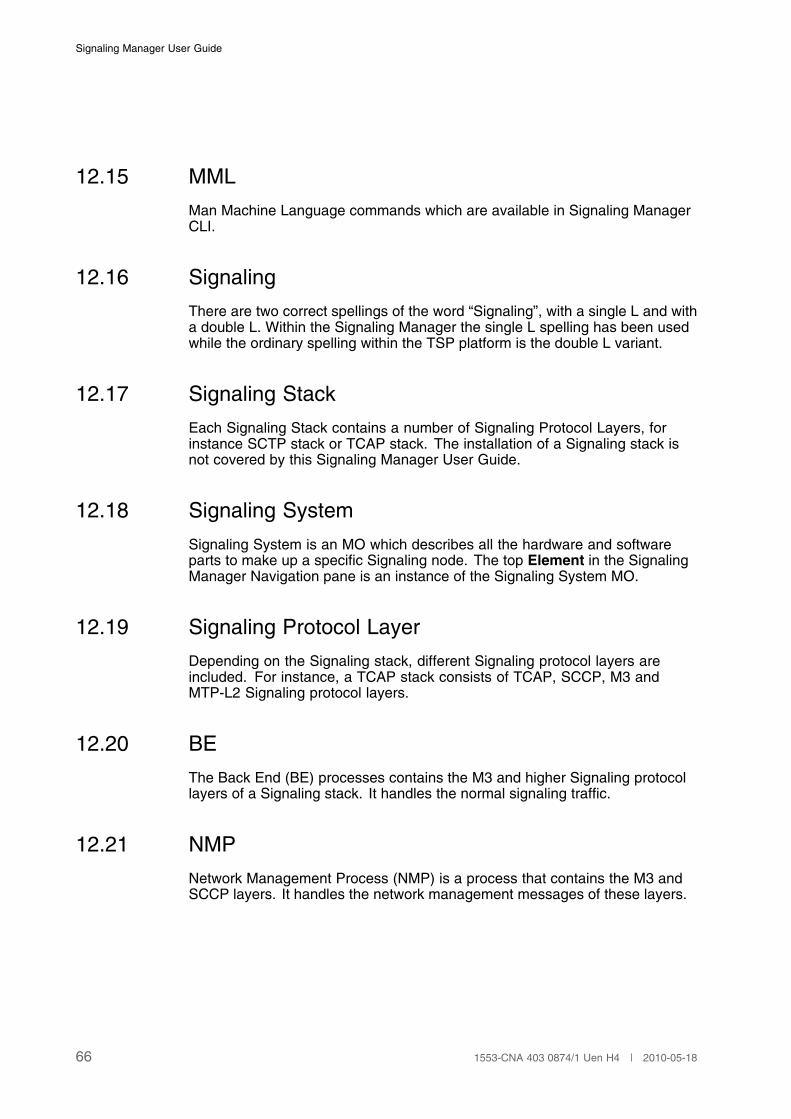
Signaling Manager User Guide
12.15 MML
Man Machine Language commands which are available in Signaling ManagerCLI.
12.16 Signaling
There are two correct spellings of the word “Signaling”, with a single L and witha double L. Within the Signaling Manager the single L spelling has been usedwhile the ordinary spelling within the TSP platform is the double L variant.
12.17 Signaling Stack
Each Signaling Stack contains a number of Signaling Protocol Layers, forinstance SCTP stack or TCAP stack. The installation of a Signaling stack isnot covered by this Signaling Manager User Guide.
12.18 Signaling System
Signaling System is an MO which describes all the hardware and softwareparts to make up a specific Signaling node. The top Element in the SignalingManager Navigation pane is an instance of the Signaling System MO.
12.19 Signaling Protocol Layer
Depending on the Signaling stack, different Signaling protocol layers areincluded. For instance, a TCAP stack consists of TCAP, SCCP, M3 andMTP-L2 Signaling protocol layers.
12.20 BE
The Back End (BE) processes contains the M3 and higher Signaling protocollayers of a Signaling stack. It handles the normal signaling traffic.
12.21 NMP
Network Management Process (NMP) is a process that contains the M3 andSCCP layers. It handles the network management messages of these layers.
66 1553-CNA 403 0874/1 Uen H4 | 2010-05-18
Signaling Manager, Terms and Abbreviations
12.22 FE
A Front End (FE) process contains a Signaling link layer that interfaces thehardware.
The type of FE used depends on the type of board providing the physicalconnection towards to the Signaling network.
12.23 Standard
Standard is a value set on system levels as well as on various configurationlevel such as Signaling System, TCAP, Signaling Network or FE. The standarddetermines available operations in Signaling Manager as well as value rangesand other validation rules. See Section 3.2 on page 6 for further details.
12.24 MFS
Multiple File System. Used for distributing an SS7 configuration to multiplehosts.
671553-CNA 403 0874/1 Uen H4 | 2010-05-18

Signaling Manager User Guide
68 1553-CNA 403 0874/1 Uen H4 | 2010-05-18
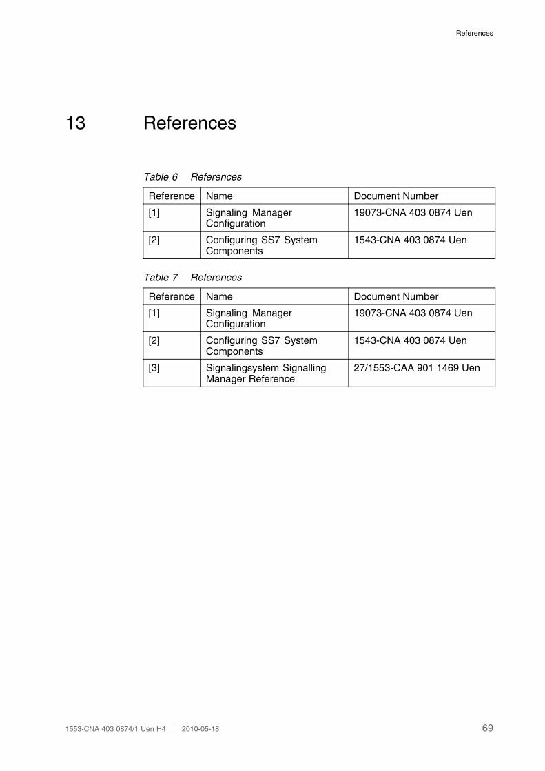
References
13 References
Table 6 References
Reference Name Document Number
[1] Signaling ManagerConfiguration
19073-CNA 403 0874 Uen
[2] Configuring SS7 SystemComponents
1543-CNA 403 0874 Uen
Table 7 References
Reference Name Document Number
[1] Signaling ManagerConfiguration
19073-CNA 403 0874 Uen
[2] Configuring SS7 SystemComponents
1543-CNA 403 0874 Uen
[3] Signalingsystem SignallingManager Reference
27/1553-CAA 901 1469 Uen
691553-CNA 403 0874/1 Uen H4 | 2010-05-18

Signaling Manager User Guide
70 1553-CNA 403 0874/1 Uen H4 | 2010-05-18
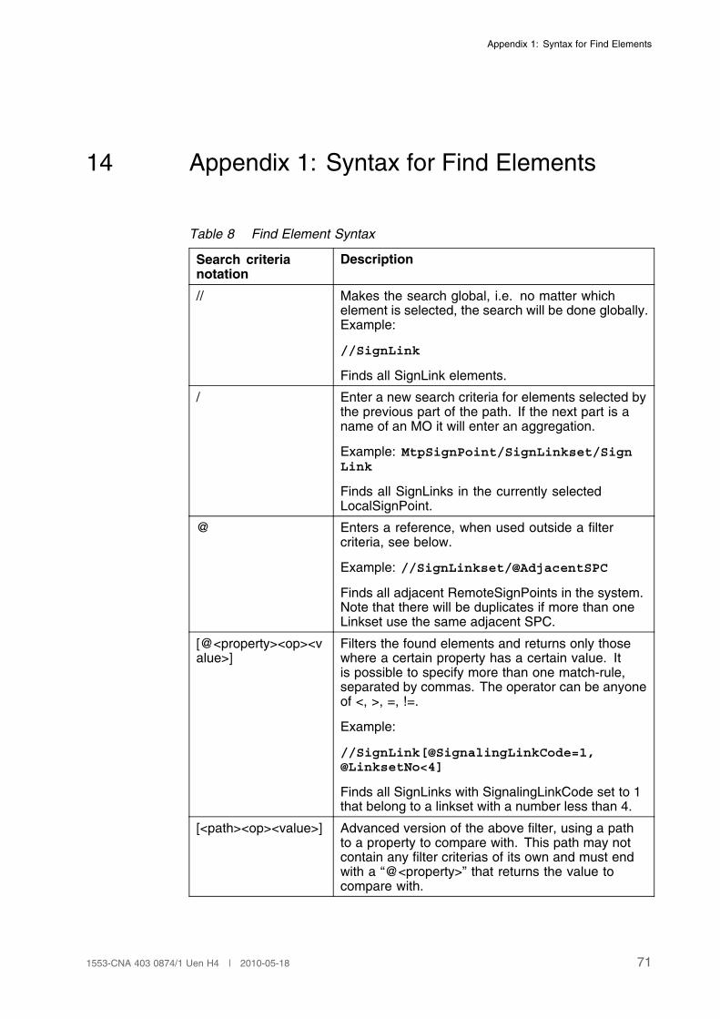
Appendix 1: Syntax for Find Elements
14 Appendix 1: Syntax for Find Elements
Table 8 Find Element Syntax
Search criterianotation
Description
// Makes the search global, i.e. no matter whichelement is selected, the search will be done globally.Example:
//SignLink
Finds all SignLink elements.
/ Enter a new search criteria for elements selected bythe previous part of the path. If the next part is aname of an MO it will enter an aggregation.
Example: MtpSignPoint/SignLinkset/SignLink
Finds all SignLinks in the currently selectedLocalSignPoint.
@ Enters a reference, when used outside a filtercriteria, see below.
Example: //SignLinkset/@AdjacentSPC
Finds all adjacent RemoteSignPoints in the system.Note that there will be duplicates if more than oneLinkset use the same adjacent SPC.
[@<property><op><value>]
Filters the found elements and returns only thosewhere a certain property has a certain value. Itis possible to specify more than one match-rule,separated by commas. The operator can be anyoneof <, >, =, !=.
Example:
//SignLink[@SignalingLinkCode=1,@LinksetNo<4]
Finds all SignLinks with SignalingLinkCode set to 1that belong to a linkset with a number less than 4.
[<path><op><value>] Advanced version of the above filter, using a pathto a property to compare with. This path may notcontain any filter criterias of its own and must endwith a “@<property>” that returns the value tocompare with.
711553-CNA 403 0874/1 Uen H4 | 2010-05-18
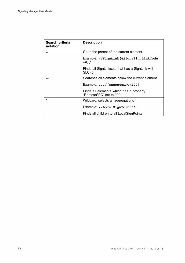
Signaling Manager User Guide
Search criterianotation
Description
.. Go to the parent of the current element.
Example: //SignLink[@SignalingLinkCode=0]/..
Finds all SignLinksets that has a SignLink withSLC=0.
... Searches all elements below the current element.
Example: .../[@RemoteSPC=200]
Finds all elements which has a property“RemoteSPC” set to 200.
* Wildcard, selects all aggregations
Example: //LocalSignPoint/*
Finds all children to all LocalSignPoints.
72 1553-CNA 403 0874/1 Uen H4 | 2010-05-18