Embed Size (px)
Citation preview

Tunnels Study Center
Signalling and support measures for self-evacuation
of users from road tunnels
www.cetu.developpement-durable.gouv.fr
Information documents
september 2010

2
DISCLAIMERThe objective of information documents is to provide information on a technique or a new problem not sufficiently dealt with elsewhere. The reader can find in these documents leads that can help him in his activity. The contents and any conclusions that may be presented should not be considered as recommendations of the CETU. Even though maximum care has been taken to ensure the reliability of the sources used, CETU or the authors of the document shall not be liable in any way.

3
Information documents
Signalling and support measures for self-evacuation of users from road tunnels
september 2010
Tunnels Study Center25, avenue François MitterrandCase n°169674 BRON - FRANCEPhone. 33 (0)4 72 14 34 00Fax. 33 (0)4 72 14 34 30
cetu@developpement-durable.gouv.frwww.cetu.developpement-durable.gouv.fr

4
The summary chapter (chapter 8) proposes a direct reading of the entire model. It uses the following outline:
• Regulatory measures: These may be requirements applicable to all the tunnels (requirements specified in the order dated 24 November 1967, modified, relating to the signalling on roads and highways and the inter-ministerial instruction, modified, on road signs), or specifically to those for which the technical instruction enclosed with the circular n° 2000-63 dated 25 August 2000 is applicable;
• Support measures meant for ensuring overall coherence in the territory, with a particular lighting of monitored tunnels of degrees D3 and D4;
• Additional measures under experimentation that may be considered for sensitive tunnels, that is, urban tunnels with dense traffic or where traffic congestion makes it difficult for user to perceive real crisis situations.
Signalling meant for intervention and rescue services is not within the scope of this document.
Over the last few years, major works have been completed or are in progress for improving the safety of users in case of fire situation in road tunnels. Feedback from such situations shows a significant gap between the expected behaviour of users and their real behaviour.
Based on this evidence, CETU undertook in 2005 an ambitious research programme for studying human and organisational factors with a view to improving the safety. This research activity has produced significant advances in our knowledge of this subject. The objective of this document is to put to good use the conclusions drawn from this research in order to show how it is possible to develop systems dedicated to self-evacuation of users. It is meant for road tunnel project managers, tunnel operating bodies, main contractors and more generally, all the players involved in the safety of road tunnels.
The chapter 1 of this document reviews current knowledge regarding the behaviour of users and their expectations in crisis situation. It presents notably a proposal of evacuation model, extending from a learning phase for the user to his return to the vehicle at the end of event.
The chapters 2 to 7 describe the measures relating to each phase of this model.
INTRODUCTION
5
1. Knowledge regarding behaviour of users and their expectations in crisis situation 6 1.1 Context of safety in a road tunnel 6 1.2 Recent research and studies 6 1.3 Main lessons learned 7 1.4 Adapting safety equipment to user needs 10
2 Learning phase or normal crossing situation 12 2.1 Regulatory measures 12 2.2 Other measures 14
3 Event detection phase and tunnel operating body alarm phase 17
4 General user alarm phase 18 4.1 Regulatory measures 18 4.2 Other measures 18
5 Tunnel evacuation phase 21 5.1 Regulatory measures 21 5.2 Other measures 21
6 Evacuation phase in emergency exit and waiting for rescue services 22 6.1 Regulatory measures 22 6.2 Other measures 22
7 Phase of return to vehicle and end of event 26 7.1 Regulatory measures 26 7.2 Other measures 26
8 Summary of different measures 27 8.1 Regulatory measures 28 8.2 Support measures 29 8.3 Additional measures applicable to sensitive tunnels 30
9 Conclusion and elements for the deployment of equipment in road tunnels 31
Appendices 32 Appendix A: Reminder of regulations on road signs 32 Appendix B: Examples of signals according to standard NF X 08-003-3 34 Appendix C: Recommendations for the layout of visual messages installed in emergency exits and to the exterior 35 Appendix D: Regulation on translation of messages 37 Appendix E: Results of experiment conducted in the Moulin tunnel (A86) 38 Appendix F: Experimental procedure for innovative devices 39 Appendix G: Example of alarm devices activation scenario 40
CONTENTS

6
• Fire behaviour of structures • Communication and transport of information • Organisation of surveillance, interventions and operations.
Regarding the second point, the instruction emphasises the means offered to users for their protection as well as evacuation, with special attention to actions before the arrival of rescue. During this period, critical for survival, the users have to rely on their own initiatives.
The most significant developments on this point have led to an increase in the number of emergency exits, reinforcement of equipment for communicating with the users and a special effort on signalling. In this context, in the event of crisis, the users are expected to quit their vehicles and proceed on foot to the emergency exits. Now, an analysis of various events, in new or refurbished tunnels, shows that very often do not behave as described in regulatory measures. They prefer wai-ting in their vehicles or evacuating the structure by making a U-turn or driving in reverse gear – rather than leaving the vehicle and reaching the emergency exit on foot.
Whether or not it is the result of an accident, the consequen-ces of a vehicle catching fire in a road tunnel can assume catastrophic proportions in terms of human lives lost. This was seen during three major fires that took place in Europe between 1999 and 2001 leading to a total of 62 deaths. The fire in Mont-Blanc tunnel had a severe impact on the public opinion and mobilised the attention of public authorities on the question of safety in road tunnels.
Since 1999, a certain number of texts have progressively specified the procedures and technical measures to be followed in tunnels longer than 300 m. Among these texts, the technical instruction of 2000 (Appendix 2 of the circular 2000-63) forms a reference base of all technical measures used by all project owners: civil engineering requirements, safety equipment, fire behaviour and operational aspect are explained. Among the-se points that have to be studied carefully while implementing safety measures in a tunnel, we mention in particular:
• Prevention by controlling traffic conditions • Measures for assisting the evacuation of persons • Provision for ventilation and smoke extraction
• Thesis on feedback
The CETU, the Société Française du Tunnel Routier du Fréjus and the École des Mines de Paris centre for risk studies have created a partnership for preparing a thesis for developing the feedback from road tunnels into a tool for studying human behaviour. Research work by a doctorate level psychologist was conducted from 2006 to 2009. It allowed; among others, to collecting recollections from persons having lived through events in road tunnels or during exercises involving persons not among the tunnel operating body’s service personnel.
Our knowledge of behaviour is based on different research pro-jects and studies:
• Project ACTEURS1
From 2003 to 2006, several concessionaires of highways2, the CETU and Dédale, company specialising in the study of human factors in risk situations, came together for a joint project: the ACTEURS project. Its objective was to better understand and improve the interaction between users, tunnel operating body and tunnels.
KNOWLEDGE REGARDING BEHAVIOUR OF USERS AND THEIR EXPECTATIONS IN CRISIS SITUATION
1
CONTEXT OF SAFETY IN A ROAD TUNNEL 1.1
RECENT RESEARCH AND STUDIES1.2
1: ACTEURS Project for improving the link between Tunnel, Tunnel operating body and User in order to strengthen safety / 2: SFTRF, APRR, AREA, ATMB, COFIROUTE, GEIE-TMB and ESCOTA.

7
KNOWLEDGE REGARDING BEHAVIOUR OF USERS AND THEIR EXPECTATIONS IN CRISIS SITUATION
The additional systems described below are based notably on the results of evaluation of equipment tested on this mock-up.
• CETU’s priority research orientation
During the period 2004 to 2008, CETU has developed a priority research orientation that integrates human factors in the safety of road tunnels. With regard to inputs on the behaviour of users, the work of CETU is based on the projects presented above as well studies and research on road safety in open air and on various crisis situations in different domains (fire in buildings, natural catastrophes, etc.).
• DIRIF3 study
In order to meet the objectives relating to the self-evacuation users in tunnels in Paris Region not-conceded by the govern-ment, an interactive method of working has allowed developing the self-evacuation support system in stages. To start with, creativity sessions with the participation of specialists have allowed proposing different systems that were tested on paper with a first panel of users. Based on this evaluation, the proposals were progressively refined. A real-scale experi-ment was conducted at the site of Moulin tunnel on A86 hi-ghway. The system was tested by a panel of volunteer users.
directly outdoors or to the other tube of the tunnel (whereas these tunnels have only one tube). More than an anecdote, this reveals mainly that the users do not project themselves into the functioning of the system. Thus, in case of crisis, they do not consider evacuating on foot via the emergency exits but they prefer to get out in their vehicles, from the entrance.
In addition to improving our knowledge concerning the beha-viour of users in normal tunnel crossing situation, this project has allowed the development of a first psycho-sociological model of evacuation5 based on a bibliographic study of published works on crises in confined environment. In this model, the evacuation process is described as a succession of stages corresponding to interactions of users with the environment and it is structured around four phases:
• Initiation of the event • Perception and recognition of alert signals • Decision to evacuate • Movement towards emergency exits.
Each phase is studied in detail with identification of factors likely to improve or delay the evacuation process for ensuring the safety of users. These factors consist principally of: the characteristics of users (prior knowledge of tunnels or crisis situations with their associated risks, etc.), characteristics of the tunnel (type of surveillance, training of personnel, type of exits, etc.) and contextual events (distance from the event, dynamics of fire growth, etc.). This model could be supported during the project only by a few interviews with persons having faced events in tunnel.
The studies make efforts to explain the gap between the expected behaviour and the real behaviour of users in a serious incident occurring inside a road tunnel. The main purpose of these studies is to adapt the safety equipment to the users. Of course, other support actions have to be applied for training the users in the principles of evacuation and to make them aware of the functioning of structure.
1.3.1 Knowledge of evacuation behaviour
• ACTEURS project model
This project has notably provided elements allowing the understanding of user behaviour in normal situation as well as in crisis situation.
Thus, the results of a large survey4 covering 619 users of the Rhône-Alpes highway network indicate that 71% of drivers consider the tunnel crossing time indifferent, for 8% even restful (night lighting, no rain, fog or snow). Only 20% declare that they found crossing of tunnel stressing. One can measure from this a first gap between representation of these structures by the users and that of the tunnel specialists who consider them complex industrial systems involving risks. A second lesson of this survey is that the users are not aware of the safety equipment provided for them in the tunnels or with the associated evacuation strategies. In fact, 10 to 20 % of Fréjus and Mont-Blanc tunnel users feel that the exits lead
MAIN LESSONS LEARNED1.3
3: DIRIF: Inter-departmental Directorate of Roads, Paris Region. / 4: Survey conducted in 2004, as part of the ACTEURS project / Reference ACTEURS - Lot 1 – Research Report no. 2: Behaviour of users in normal tunnel crossing situation p. 93. / 5: Reference ACTEURS - Lot 1 – Research Report no. 2: Behaviour of users in normal tunnel crossing situation.
8
1
• Research at TNO6
A study conducted by TNO in Holland7 indicates that users of road tunnels are not conscious of inherent dangers during a fire in tunnel. During a series of seven tests, a group of 40 drivers enters a road tunnel behind a truck. In the middle of the struc-ture, the heavy vehicle stops across the road pavement and smoke starts escaping from it. The observation of drivers’ behaviour allows establishing the length of response time of the users (more than 6 minutes) and an effective evacuation only in case a spoken message informs the users of a risk of explosion. In one of the tests, the users remained in their vehi-cles entirely surrounded by smoke.
• Lessons from other domains
Besides these projects focussing on knowledge of behaviour in tunnel, studies conducted by North American researchers8 on behaviour observed during fire in various places show that the users find it very difficult to interrupt their activity in progress: shopping in a store, visiting a museum, doing normal work, watching a movie or a sports event, etc. In these contexts, the simple activation of a siren is not sufficient to initiate the evacuation. Only a radical change of the environment makes them aware of a change in the situation and the need for evacuation (stopping of music in a store, lights coming on in a cinema hall and interruption of the film, stopping of the match, etc.). It is therefore necessary to send a strong message so that the person becomes conscious of the obligation to evacuate. This message can be all the more efficacious when it combines and sequences visual and audio communication modes. Lastly, these studies highlight that in a public place (store, museum, stadium, etc.), the persons expect to be taken charge of by an authority and that their lack of initial reaction is explained also by the fear of having an inappropriate and disproportionate reaction with regard to a situation that may finally prove to be not at all catastrophic.
1.3.2 Mental representations For B. de Vanssay9, the analysis and management of crisis situations requires working on the representations of each of players for establishing efficacious prevention plans. This allows understanding approaches of different players in crisis management that may be contradictory at times. In fact, a subject or a group deals with a given situation based on a set of pre-conceived ideas, pre-established thought processes and interpretative schemas. This results in a reconstitution of the reality that is in face by attributing to it a specific significance that in turn allows the interpretation of events, anticipation of possible ways in which the situation may develop – in order to decide on the behaviour to be adopted.
The question that is then posed concerns the representation of the “tunnel object” and its associated risks by different players. For answering this, a work on the representations was one of the principal aspects of a thesis10 whose objective was to collatethe feedback from road tunnels in order to create a tool for studying human behaviour.
• Vocabulary and spatial representations by drawing techniques
A first approach consists in understanding how the different players involved in the safety of the tunnel “see” the structure and the vocabulary used by them. The experimental proto-col is based on the use of drawings for illustrating the mental representations of the tunnel object. The following instruction is given: “Draw a tunnel using the elements that are the most important for you.” About a hundred persons participated in this experiment.
The results obtained show that in general, all the tunnel operating body and designers base their drawing on the technical elements that are important for their activity and on the equipment necessary for the safety of users. However, it may be noted that the designers and the tunnel operating bodies do not always use the same terms for designating a given element. From their side, the users draw the elements essential for driving a vehicle inside a tunnel, these being: lighting and police signalling. In most cases, the terms used are not the same as those used by the operating personnel and the designers. When tunnel specialists make a distinction between “direct communications with the exterior, shelters, inter-tube, emergency stations, fire recess,” the user evokes “things for safety,” mixing up all these devices. Another important variation in the representations of different players is the angle of sight. In fact, when the tunnel operating bodies represent the tunnel in supervision view (as in the control rooms), the user represents a hole in a mountain in front view. For the driver of a vehicle, the tunnel is a covered portion of his route.
This work on representations illustrates the differences in the level of representation between the tunnel operating bodies, designers and users. This difference in representation may lead to difficulties of communication and understanding between these players, notably in crisis situations, between an tunnel operator at the control station and a user. That is why, for example, the message “Go in Shelter” is often not understood while “Go to the Shelter” produces the expected reaction.
• Vocabulary and representation by collecting accounts
A second approach to the work on representations consists in collecting accounts of experiences undergone by users during
6: TNO is a Dutch organisation for applied scientific research / 7: Boer, L.C. (2002). Behaviour by motorists on evacuation of a tunnel. Centre for tunnel safety, TNO Human Factors http://www.minvenw.nl/rws/bwd/home/pdf/ tunnel tno/tnorep.pdf / 8: Reference: Articles "How to make sure the occupants react to fire alarms" - IRC / CNRC and "Some false ideas on the behaviour of persons during fire” by Guilène Proulx. / 9: B. de VANSSAY. "Incredulity faced with risks. Contribution of social and environmental psychology.” International seminar on human behaviour when faced with fire and other danger situations, University of Cergy-Pontoise, 12 October 2006. / 10: The CETU, the Société Française du Tunnel Routier du Fréjus and the risk studies centre of the École des Mines de Paris have set up a partnership for the preparation of this thesis.

9
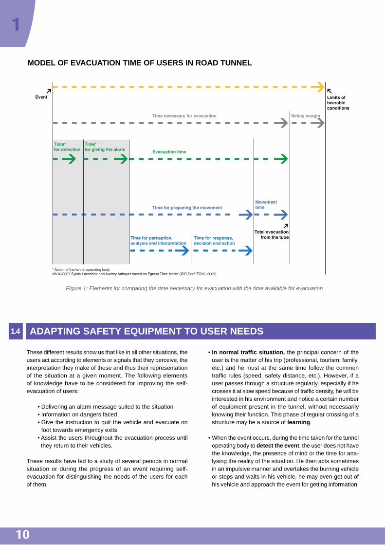
1.3.3 Model of evacuation timeThe first elements of feedback based on case-studies and the recollections of protagonists have allowed confirming that a model distributing the evacuation time of users was identical to the model used by Canadian researchers while studying fires of individual houses11 (cf. Figure 1).
This model illustrates the fact that contrary to what one may desire, the evacuation behaviour does not start with the fire. This model shows that it is necessary to break down the time available in principle for the evacuation12, this time is divided into several steps:
• A time for detecting the event and a time for giving the alarm
• A time when the user prepares himself for moving in the tunnel (time when he analyses the situation and decides how he should act)
• The time when the user moves on foot in the tunnel towards the emergency exits.
We can thus see that the time during which the users are on foot inside the tunnel is very short compared with the time when the conditions are bearable; we can also see that this time is situated during the period when conditions inside the structure are already degraded.
Consequently, it is necessary to act so that the time for analysis and decision is efficacious, so that information and pedagogy are effective in making this time for reflection lead rapidly to a self-evacuation on foot.
crisis situations in road tunnel. This allows refining our unders-tanding of the ways in which the users represent the situation during different phases of the event, thereby better analysing their behaviour.
These are some of the recurrent recollections:
• “We do not know what happens.” The users do not understand the nature of the event; this leads them to wait in their vehicle or to go see what has happened by approaching the incident.
• “I thought it was an exercise.” The human being always tends to minimise the situation and the dangers, He tries to reassure himself and thinks that such events only happen to others.
• “I did not think that it was serious, one needs to be frightened. ” These statements reveal a lack of know- ledge about the consequences of fire in a tunnel.
• “We did not know what to do.” Higher the service level as perceived by the user, greater the tendency to expect that he should be told what to do and looked after. On the other hand, in a public place, persons are often afraid of showing an exaggerated reaction and because of this, they look at what others are doing and wait for someone to take a decision so that they can copy the behaviour.
• “One wonders how long it is going to last,” and “We do not know if we can find our car again.” When the users eva-cuate on foot and wait in a shelter or outside the tunnel, they always need information and ask to know what is happening in the tunnel. The waiting time seems unbea-rable and if they do not obtain information in real time, they do not hesitate to return inside the tunnel for finding out how the situation is developing and the condition of their vehicle.
In addition, personal imperatives, concern for continuing their travel as well as their reluctance in leaving the comfort of their car are other elements that obstruct the users from taking the decision to leave the vehicle. They often wish to escape on board their vehicles.
11: Research report: -IRC-RR-209 - Egress times from single family houses - July 12, 2006 - Proulx, Cavan and Tonikian. / 12: Time available in principle for the evacuation = time during which bearable conditions for the human organism are available.
10
1
• In normal traffic situation, the principal concern of the user is the matter of his trip (professional, tourism, family, etc.) and he must at the same time follow the common traffic rules (speed, safety distance, etc.). However, if a user passes through a structure regularly, especially if he crosses it at slow speed because of traffic density, he will be interested in his environment and notice a certain number of equipment present in the tunnel, without necessarily knowing their function. This phase of regular crossing of a structure may be a source of learning.
• When the event occurs, during the time taken for the tunnel operating body to detect the event, the user does not have the knowledge, the presence of mind or the time for ana-lysing the reality of the situation. He then acts sometimes in an impulsive manner and overtakes the burning vehicle or stops and waits in his vehicle, he may even get out of his vehicle and approach the event for getting information.
These different results show us that like in all other situations, the users act according to elements or signals that they perceive, the interpretation they make of these and thus their representation of the situation at a given moment. The following elements of knowledge have to be considered for improving the self- evacuation of users:
• Delivering an alarm message suited to the situation • Information on dangers faced • Give the instruction to quit the vehicle and evacuate on
foot towards emergency exits • Assist the users throughout the evacuation process until
they return to their vehicles.
These results have led to a study of several periods in normal situation or during the progress of an event requiring self- evacuation for distinguishing the needs of the users for each of them.
ADAPTING SAFETY EQUIPMENT TO USER NEEDS1.4
Figure 1: Elements for comparing the time necessary for evacuation with the time available for evacuation
Event
Temps disponible pour l'évacuation
Time necessary for evacuation Safety margin
Time for preparing the movement
Time for perception,analysis and interpretation
Time for response,decision and action
Movementtime
Evacuation time
Limits ofbearableconditions
Time*for detection
Time*for giving the alarm
Total evacuationfrom the tube
* Action of the tunnel operating body08/10/2007 Sylvie Lavedrine and Audrey Auboyer based on Egress Time Model (ISO Draft TC92, 2005)
MODEL OF EVACUATION TIME OF USERS IN ROAD TUNNEL

11
13: Cf. Chapter 13 for the definition of terms “alert” and “alarm”
Consequently, in the absence of alarm signal13, it is gene-rally difficult for him to understand the situation for reacting to it (nature of event, danger involved, instructions to be followed). The importance for him is to understand that the situation is no longer normal, that it has changed to a crisis situation and that it is not possible for him to continue his journey; at this stage, if the danger is not clearly identified, it is the need for continuing his journey that will remain his principal concern. During this phase, it is also necessary to consider the diversity of users and expect a wide variety of reactions (single person, several adults, professionals of the road, family with children, persons of reduced mobility though not on wheelchairs, etc.).
• Once the user has quit his vehicle, it is desirable to guide him to an exit, even if the conditions are highly degraded and to continue informing him of the danger. In case of doubt regarding the conduct to be followed, there will be a strong temptation to return to the vehicle.
• When the user is in the exit, it is desirable to give him clear instructions on what he should do (wait, move outdoors) and to stress that he is safe in the exit (resistance to fire, fresh air, etc.). Here again, it is necessary to keep in mind that the diversity of users does not make things easier (different rates of movement in the tunnel and in the exit, persons going back to get something or find someone, persons carrying baggage, etc.). Moreover, when the users are alone in the exit or outdoors, the waiting time appears unbearable beyond 10 minutes. We can then observe persons who return to the tunnel to see what is happening or saturating the control station with calls from the emer-gency phone network. It is therefore desirable to quickly take charge of persons who are waiting. At this stage, the users are asking how long it is going to take, if they can recover their vehicle, whether someone is coming to collect them, etc.
• Lastly, the difficulty of evacuating the users on foot to the exits should not distract from the need for assisting them during the return to normal. It is desirable to give a signal at the end of the event, inform what has happened and to give clear instructions leaving no room for interpretation.
The measures described in the following chapters are meant for informing and assisting the users during each of these periods.
Based on the elements described above, the question arises, firstly the best way of using regulatory safety equipment presently available and secondly, the advantage of setting up additional measures that can help in the evacuation of persons present in the tunnel when the rescue services have not yet arrived.
In order to be effective, the solutions retained have to take into account the following principles:
• Give information coherent with what can be observed in the structure focussing on the reality of events taking place and the associated dangers
• Give this information in good time by adapting it in the tunnel depending on the location
• Multiply the communication modes as much as possible, for example, by combining visual and sound messages.
We must not forget that less one is familiar with a situation, more one needs to understand and to be helped, because each person always tries to hold on to a personal experience.
As indicated in the preamble, the following part of this document gives indications for guiding the decision maker in the choice of priorities for applying these measures. The summary chapter (chapter 8) proposes a direct reading of measures according to typology of the structure.

12
Studies have shown the critical importance of learning the safety measures by the user. This learning should be nourished by observation in normal situation of tunnel crossing. It is for this reason that the safety measures, notably signalling, meant for drawing attention to the safety equipment provided to the users are described in this chapter.
REGULATORY MEASURES 2.1
2.1.1 Signalling of emergency exits
The article 78-26 §1 of the fifth part of inter-ministerial instruction on road signs stipulates the following points:
• Signalling of emergency exits leading to open air, in a tunnel or a parallel gallery or in a local safeguarding the users, is obligatory. It should be provided using panels of type CE30. A CE30a panel and a CE30b panel should be installed in front of the emergency exit, one of them visible from the direction of traffic and the other in the opposite direction.
The decoration of CE30 type panel should also be placed on the access door of the emergency exit. It should be placed so that it is coherent with the door opening direction.
• It is obligatory to install distance markers to the emergency exits for pedestrians. Panels of type Dp2a and Dp2b should be used for this purpose.
A Dp2a panel and a Dp2b panel are installed in pairs, parallel to the road direction, every 25 m.
2.1.2 Signalling of emergency stations
Inter-ministerial instruction on road signs specifies that the emergency stations are not indicated as such but rather, according to the equipment they contain, such as emergency telephone or fire-fighting equipment for the tunnel users.
• Signalling of emergency telephones
The article 78-1 of the fifth part of inter-ministerial instruction on road signs specifies that two CE2a panels should be installed in front of the emergency telephone, one of them visible from the direction of traffic and the other in the opposite direction.
Note: The distance has to be marked appropriately in each panel.
CE30b panel CE30a panel
CE2a panel
LEARNING PHASE OR NORMAL CROSSING SITUATION
2
Dp2a panel
Generally in tunnels, the CE2a panel are not installed as advance signs. However, in case of insufficient or late visibility of CE2a panel in position, it can be installed as advance signs. It should then be completed by M1 panel indicating the distance to the emergency telephone (cf. § 2.1.3).
• Signalling of fire-fighting equipment
The article 78-25 of the fifth part of inter-ministerial instruction on road signs specifies that the signalling of fire-fighting equipment meant for tunnel users is obligatory inside tunnels. The CE29 panel should be used for this purpose. If the fire-fighting equipment is installed at the location of a lay-by, the signalling should be provided by means of a C8 panel, completed by M9 panel (cf. § 2.1.3).
Dp2b panel

13
The C8 is generally not installed as advance signs because of the reduced distance between equipment to be signalled inside the tunnels. However, in case of insufficient or late visibility conditions of the C8 position panels or if the C8 position panel is replaced by a CE30 type panel, the C8 panel can be installed as advance sign. It should then be completed by the Ml panel.
2.1.4 Installation and lighting of regulatory panels
• Lighting of panels
The article 76-2 of the fifth part of inter-ministerial instruction on road signs specifies that in tunnel:
• The CE29, CE30a and CE30b panels should be luminous and retroreflective
• The CE2a panels should be retroreflective • The Dp2a and Dp2b panels should be retroreflective
or luminous (the Dp2 photo-luminescent panels are described in §2.2.1).
It may be noted that the article 3.7.1 of the technical instruction 2000 specifies that the signalling panels of safety facilities accessible to the users must be luminous. In practice, the CE2a panels are not only retroreflective but also luminous because of their installation near CE29, Dp2a and Dp2b panels which are very often only retroreflective.
• Size of panels
It may be noted that as a general rule, the panels should be of standard size (700 mm x 700 mm) and that panels of small size (500 x 500) should be used only in existing structures where sufficient width is not available for installing the standard size panels. The miniature size (350x350) should be used only in exceptional cases because it does not allow easy identification of useful equipment in case of incident.
• Position of panels
The CE30, CE29 and CE2a panels should be installed in front of the equipment signalled by them, perpendicular to the wall.
LEARNING PHASE OR NORMAL CROSSING SITUATION
Two CE29 panels should be installed in position, in front of the equipment: one of them visible in the traffic direction and the other in the opposite direction. The CE29 panel is generally not installed as advance sign.
2.1.3 Signalling of lay-bysThe article 70-6 of the fifth part of inter-ministerial instruction on road signs specifies that in tunnels, the signalling of lay-bys is obligatory. It should be provided by means of C8 panel that should be installed as signalling of position.
The signalling described in § 2.1.1 and 2.1.2 should also be applied if the lay-by has an emergency exit and/or the equipment of an emergency station.
If lay-by has an emergency exit, the C8 panel should be accompanied by a CE30 type panel. If technical reasons do not allow the installation of two panels, only the CE30 type is installed. The C8 panel should be completed by the M9e panel if the lay-by included an emergency telephone. It should be completed by the M9f panel if the lay-by includes an emergency telephone as well as fire-fighting equipment accessible to road users.
CE29 panel
Example of M1 panel
C8 panel
M9f panelM9e panel
14
2
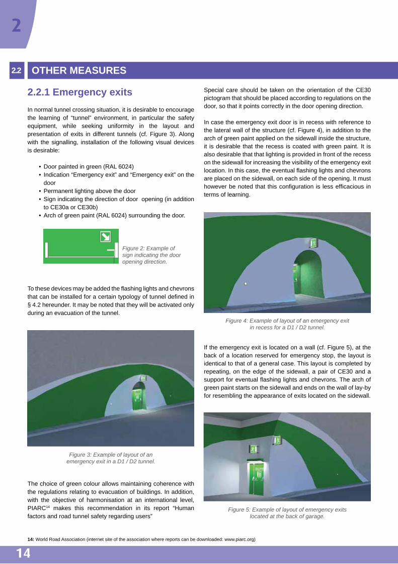
2.2.1 Emergency exitsIn normal tunnel crossing situation, it is desirable to encourage the learning of “tunnel” environment, in particular the safety equipment, while seeking uniformity in the layout and presentation of exits in different tunnels (cf. Figure 3). Along with the signalling, installation of the following visual devices is desirable:
• Door painted in green (RAL 6024) • Indication “Emergency exit” and “Emergency exit” on the
door • Permanent lighting above the door • Sign indicating the direction of door opening (in addition
to CE30a or CE30b) • Arch of green paint (RAL 6024) surrounding the door.
To these devices may be added the flashing lights and chevrons that can be installed for a certain typology of tunnel defined in § 4.2 hereunder. It may be noted that they will be activated only during an evacuation of the tunnel.
The choice of green colour allows maintaining coherence with the regulations relating to evacuation of buildings. In addition, with the objective of harmonisation at an international level, PIARC14 makes this recommendation in its report “Human factors and road tunnel safety regarding users”
OTHER MEASURES2.2
14: World Road Association (internet site of the association where reports can be downloaded: www.piarc.org)
Special care should be taken on the orientation of the CE30 pictogram that should be placed according to regulations on the door, so that it points correctly in the door opening direction.
In case the emergency exit door is in recess with reference to the lateral wall of the structure (cf. Figure 4), in addition to the arch of green paint applied on the sidewall inside the structure, it is desirable that the recess is coated with green paint. It is also desirable that that lighting is provided in front of the recess on the sidewall for increasing the visibility of the emergency exit location. In this case, the eventual flashing lights and chevrons are placed on the sidewall, on each side of the opening. It must however be noted that this configuration is less efficacious in terms of learning.
If the emergency exit is located on a wall (cf. Figure 5), at the back of a location reserved for emergency stop, the layout is identical to that of a general case. This layout is completed by repeating, on the edge of the sidewall, a pair of CE30 and a support for eventual flashing lights and chevrons. The arch of green paint starts on the sidewall and ends on the wall of lay-by for resembling the appearance of exits located on the sidewall.
Figure 4: Example of layout of an emergency exit in recess for a D1 / D2 tunnel.
Figure 3: Example of layout of an emergency exit in a D1 / D2 tunnel.
Figure 2: Example of sign indicating the door opening direction.
Figure 5: Example of layout of emergency exits located at the back of garage.

15
• Pedestrian distance markers for emergency exits
If the exits are all positioned on the same side of the tube, the Dp2 type panels should be installed only on the wall where the exits are located, with distance markers in the same way for the exits that form the tunnel heads.
It is also worth trying to indicate the exit for the user in evacuation along the opposite wall. In the absence of precise evaluation of equipment that can be considered, the following layout can be proposed: CE30 + M3b panel to be installed on the sidewall in front of the exit (cf. Figure 6). This equipment should be lit continuously and should be positioned perpendicular to the sidewall, at about 1.5 m height in order not to disappear completely in the smoke. However, the optimum installation of this panel should be adjusted for each case in order to avoid that it creates an obstacle on the pavement. The installation of this type of equipment requires an application for experimentation to be submitted to the DSCR because it is not currently provided under road signs regulations.
This equipment can also be replaced by the panel shown below (reference: AFNOR 50040 Rev) if there is enough place.
If there are exits located on each side of the tube, a detailed study is necessary for selecting the most effective location of the Dp2 for a proper understanding by the users. The conclusions of this study depend on the specific configuration of exits. For tunnels longer than 300 m without emergency exit, it is good to indicate distances to the heads on at least one of the sidewalls using Dp2.The Dp2 panels are positioned at a height of about 1.5 m.
15: RAL 2009 is also suited. However, RAL 2008 tends to turn towards yellow under high-pressure sodium lighting.
It may be noted that the retroreflective Dp2 disappear very quickly when the lighting on top part of the tunnel is filled with smoke, depriving the users of precious guidance to the emergency exits. An alternative to the lighting of these panels (that may be quite costly) is photoluminescence. However, at present, the installation of photoluminescent Dp2a and Dp2b panels requires permission for experimentation from the DSCR because it is not compliant with regulatory specifications (cf. article 76-2 of the fifth part of inter-ministerial instruction on road signs).
2.2.2. Emergency stations In order to favour the perception of emergency exits by the users, it is preferable not to enhance the visibility of emergency stations. It is recommended to close the emergency stations with glass doors and apply a discreet orange surround (RAL 200415) as shown in the following example. The glass doors allow seeing the PAU from the outside and avoid giving a feeling of security in case of fire.
The technical instruction 2000 (§ 2.4) requires that all measures should be taken for informing the users that the emergency stations are not meant for protecting them in case of fire. The order dated 8 November 2006 modified imposes that tunnels longer than 500 m in the Trans-European network should have sign indicating that in case of fire, it is dangerous to remain in the emergency stations separated from the tunnel by a door (cf. article 2.j or the order). It is desirable to place such a sign in all the tunnels, irrespective of their status or length when the emergency stations are closed by a door. This sign may be inspired by the standard NF X 08-003-1 with notably black letters on yellow background as in the following example.
Figure 6: CE30b panel and M3b panel Figure 7: Example of layout of an emergency station.

1616: The procedure to be followed is described in Appendix F.w
2
Examples are given in Appendices C and D for drafting and translating the messages. The warning message should be translated in at least two languages except for binational tunnels where a single language may be sufficient (that of neighbouring country).
2.2.3 Trihedral panelsConsiderations of maintenance and/or availability of space may lead to installing the CE30, CE2a and CE29 panels at an angle larger than 90° with reference to the sidewall. This installation that is not according to regulations requires permission for experimentation from the DSCR16. This experimentation shouldbe aimed at showing that the use of such a panel is not prejudicial to the perception by users. In this context, a detailed evaluation, with notably in situ trials of evacuation, can validate this principle and examine the possibilities of optimising the angle of inclination of the panel.
2.2.4 Cohabitation of different types of signalling and different functions
In order to strengthen the perception of safety facilities, it is desirable to avoid installing traditional signalling (speed limits, safety distance, etc.) near emergency exits and emergency stations.
Care must also be taken so that the panels indicating dangers relating to the infrastructure (dangerous curves, for example) are not lost in all the signalling associated with the structure. Depending on the tunnel configuration, these danger signals may be luminous for increasing the visibility for users.
In addition, as far as possible, it is desirable to avoid a cohabitation of safety equipment meant for the users (emer-gency exits, emergency stations, etc.) with those meant for the tunnel operating body or the rescue services (fire recess, service rooms, etc.). For preventing any confusion, it is desirable that the premises meant for various intervention services are not closed by glass doors or doors painted in green or orange; they should either be open (fire recess, etc.) or closed with doors merging as far as possible in the wall (service rooms, etc.).

17
EVENT DETECTION PHASE AND TUNNEL OPERATING BODY ALARM PHASE
The first receiver of an alarm17 in tunnels, depending on the tunnel, is a rescue and fire-fighting public service, police forces, the tunnel operating body or other service. This service retransmits the alert18 to other concerned services.
The alarm may be given directly by the users using mobile phones or emergency phones. The alarm may also be forwarded by tunnel operating body services through operational tools (DAI19, video-surveillance, opacimeter, etc.).
During this phase, the tunnel operating body receives the alarm, he then confirms the event and decides on the response scenario. During the phase preceding this triggering, no means
of direct communication with the users is yet operational for assisting the users. Only training and information can lead them suspect a possible crisis situation in view of events taking place in the structure.
Feedback shows that with increasing frequency, the user uses his mobile telephone for reporting an event in the tunnel. In order to facilitate its location by the duty operator, it may be useful to study the possibility of installing positioning systems in the structure. These systems can also facilitate communication between the tunnel operating body and the intervention services in case of crisis.
17: Sound and/or visual signal alerting the personnel on duty. / 18: Action of demanding the intervention of a service concerned by a significant event. /19: DAI: Automatic Incident Detection.
3
Example of capturing a DAI Opacimeter

18
GENERAL USER ALARM PHASE
REGULATORY MEASURES4.1
The importance of this phase is to make the user understand that the situation is no longer normal, that it has changed to a crisis situation and that it is no longer possible for him to continue his journey. All approaches allowing assisting the user in taking the decision to evacuate merit being explored.
When the level of operation of the tunnel allows it, it is desirable to try and inform the user of the situation inside the tunnel and the dangers faced and if possible, to give him an evacuation instruction comparable to provisions of ERP20 and IGH21. During this phase, the sequencing of different sound and visual messages can allow clearing all ambiguity in the mind of the users regarding what is happening and to make them aware of a changeover to crisis situation. The following working approaches are under experimentation in several tunnels:
• Installation of sirens for giving the alarm • Installation of sonic beacons giving warning of danger and
giving the instruction to leave the tunnel via the exits • Activation of flashing lights and dynamic chevrons placed
on each side of the entrance of the exit • Definition of appropriate radio messages explaining the
situation and the dangers involved and giving instructions to be followed
• Association of a barrier closing access to the running section with a stop light and associated Variable Message Sign.
These measures can be considered only in tunnels with D3 or D4 surveillance, where the tunnel operating body has the capacity of triggering the process. They are particularly relevant for urban tunnels of for tunnels with recurring congestion, where the users who are habituated to slow down and stop
in the tunnel will find it hard it to distinguish between “normal” congestion situations and stoppage due to serious incidents.
• Alarm siren
The objective of the siren is not to make the users leave their vehicle immediately but rather, it is meant for making them aware that the situation has changed to a crisis situation and that they are in danger.
A system was tested during experiments in the Moulin tunnel (A86). Observation of behaviour confirms that the users remain in their vehicles during the operation of the siren. However, interviews with them show that this signal was correctly perceived as the indication of a danger, a problem in the tunnel. This led them to seeking information on what is happening and what they should do. The siren is meant for putting them in condition for action.
The siren should be oriented towards to traffic, at an angle where the reverberation phenomena do not disturb significantly the sound emitted. As far as possible, the signal emitted should be audible and understandable at any point in the structure.
It is recommended to install a siren of adjustable power (90 dB to 130 dB at 1 m22), under the intrados in front of the emergency exits.
OTHER MEASURES4.2
20: ERP – Establishment Receiving Public / 21: IGH – Very Tall Buildings. / 22: These elements are obtained from the DIRIF experiment. In any case; these references are to be studied case by case according to the acoustic environment of the structure and in situ evaluations.
At present, there is no specific regulation applicable to all the tunnels regarding alarm propagation and modalities in tunnels. However, the technical instruction 2000 provides for several measures for assisting the users in evacuating the tunnel, depending on the length and level of surveillance of structures:
• Article 3.7.2 of the technical instruction provides that inside tunnels longer than 1 000 m and with continuous D3 or D4 surveillance, lights should be placed at about every 800 m in order to stop the users driving in the
tunnel at the time the alarm is received. Each light should be associated with a variable message sign allowing informing the users of the reasons for stopping.
• Article 3.8 of the technical instruction expresses the need for retransmitting at least one frequency of a radio station broadcasting to the users, for tunnels with continuous D3 or D4 surveillance and longer than 800 m in urban and 1000 m in non-urban areas, in order to interrupt the broadcast for announcing the safety messages addressing the users.
4
19
23: These elements are obtained from the DIRIF experiment. In any case; these references are to be studied case by case according to the acoustic environment of the structure and in situ evaluations. / 24: Interview during a “User Forum” organised by the DGR in 2004.
• Sound beacons
During this phase, the purpose of sound beacons installed in front of the emergency exits is to:
• Give general alarm to the users if there is no siren • Confirm the alarm after the signal emitted by the siren by
giving information and clear instructions to the users (the message emitted “Attention - Danger – Exit here” gives them the information they need after hearing the siren)
• Help the uses locate the exit in the midst of smoke • Incite them to reach the exit.
The experiment conducted by DIRIF in the Moulin tunnel shows that the users located close to the emergency exit leave their vehicle after hearing the message announced from the beacons. The users farther from the exit leave on their turns to join those ahead who are evacuating towards the emergency exit. Interview conducted later show that this message, associated with all the measures is efficacious in triggering the evacuation decision.
The results of the DIRIF experiment lead to proposing the installation of sound beacons in front of the emergency exits above the doors (adjustable from 85 to 105 dB at 1 m23). The loudspeakers forming the beacons are arranged in pairs and oriented in each direction of the tube: one facing the vehicles and the other in the traffic direction.
It should be possible to adjust the sound level of the two beacons independently. The beacons may be preferably integrated with the horizontal support carrying the lighting in order to facilitate maintenance and cleaning, making the space around the exit quite visible.
Conforming to the provisions of Appendix D, the message emitted should be translated into only one language. It is necessary to take great care regarding the audibility of these messages. In order to facilitate the identification of two languages, it would be better to have them spoken by two different persons.
• Flashing lights
In the alarm phase, the objective of flashing lights is to provide visual information regarding the change of situation and to reinforce the sound messages. They also allow the users to identify the position of exits and to guide them in the right direction.
The experiment conducted in the Moulin tunnel shows that the flashing lights associated with the system as a whole, are determining for the evacuation decision.
For better efficacy, the flashing lights are placed in front of the entrance to emergency doors.
• Chevrons
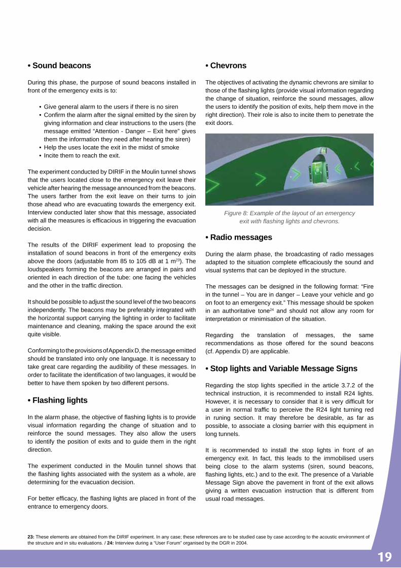
The objectives of activating the dynamic chevrons are similar to those of the flashing lights (provide visual information regarding the change of situation, reinforce the sound messages, allow the users to identify the position of exits, help them move in the right direction). Their role is also to incite them to penetrate the exit doors.
• Radio messages
During the alarm phase, the broadcasting of radio messages adapted to the situation complete efficaciously the sound and visual systems that can be deployed in the structure.
The messages can be designed in the following format: “Fire in the tunnel – You are in danger – Leave your vehicle and go on foot to an emergency exit.” This message should be spoken in an authoritative tone24 and should not allow any room for interpretation or minimisation of the situation.
Regarding the translation of messages, the same recommendations as those offered for the sound beacons (cf. Appendix D) are applicable.
• Stop lights and Variable Message Signs
Regarding the stop lights specified in the article 3.7.2 of the technical instruction, it is recommended to install R24 lights. However, it is necessary to consider that it is very difficult for a user in normal traffic to perceive the R24 light turning red in runing section. It may therefore be desirable, as far as possible, to associate a closing barrier with this equipment in long tunnels.
It is recommended to install the stop lights in front of an emergency exit. In fact, this leads to the immobilised users being close to the alarm systems (siren, sound beacons, flashing lights, etc.) and to the exit. The presence of a Variable Message Sign above the pavement in front of the exit allows giving a written evacuation instruction that is different from usual road messages.
Figure 8: Example of the layout of an emergency exit with flashing lights and chevrons.

20
4
• Police signalling
For avoiding any ambiguity, experience in the evacuation of buildings shows that it may be useful at this stage to turn off all types of luminous police signalling (speed limits, reminders of safety distances, etc.) that becomes useless when the users are waiting or are walking on foot in the tunnel, in order to increase the impact of the message that the situation has changed and that it is no longer possible to continue the voyage normally.
The application of this measure can be considered only upstream from the event, being understood that the vehicles downstream should continue progressing safely.
• Cases of using these measures
Two levels may be distinguished in the application of additional measures described above:
• 1st level: The flashing lights are already widely used in road tunnels and have proved to be efficacious in crisis situations. It is desirable to install them progressively in tunnels with D3 or D4 level surveillance.
• 2nd level: The other devices are to be tested and evaluated before their wide use. They are positive elements for improving the efficacy of self-evacuation of users in sensitive tunnels (urban tunnels with heavy traffic and/or tunnels with recurrent congestion making it difficult for users to perceive real crisis situations). They deserve to be studied in detail as is the case currently in the tunnels of Paris Region national road network. For certain urban tunnels, the national commission for evaluation of safety in road structures (CNESOR) has recommended that the tunnel managers must study the possibility of installing comparable equipment.
• Influence of these systems on behaviour of users
It is important to remember that it is the overall coherence of resources employed that makes the system efficacious.
In fact, the users are not sensitive to the same type of signals depending on situations. Interviews conducted show that certain persons react to luminous signals whereas others to not perceive them but react to sound signals.
Moreover, the starting operation of different devices with a slight shift with reference to one another leads to confirming that the situation is fast changing to a crisis situation. Each device confirms the alarm and contributes to preventing a natural behaviour of denial. A flowchart is proposed in the Appendix G. However, the precise timing should be dealt with according to an in situ evaluation trial.
Lastly, it may also be noted that during this phase, the movement of a few persons to the exits will have the consequence initiating a generalised movement of evacuation of users who are farther away from the exits. It is not therefore necessary to touch at all cost all the users at each and every place of the structure.
There is another question that is yet to be resolved completely. This is the block system (activation of measures sector-wise) for alarm equipment in long tunnels facing recurrent congestion, in order to avoid unnecessary evacuation of a too large number of persons whose safety is not at risk.

21
During this phase, the regulatory signalling described in § 2.1 helps the user locate the emergency exit.
In addition, the article 3.3 (3rd section) of the technical instruction 2000 provides that luminous markers should be placed at a height of 1 m on each sidewall and spaced at about 10 m.
They must be lit continuously, in order to provide luminous distance markings in case the smoke from fire masks the lighting placed at a height (and in case of power failure in tunnels with low traffic levels and without safety lighting).
In this phase, the objective is to guide the user in helping him find the closest exit and to move towards it, even when environmental conditions in the structure are highly degraded and in particular, when the CE30 placed above the doors are hidden by the smoke.
In addition to regulatory signalling, in the tunnels where the tunnel operating bodyhas the capacity of initiating the process, it is recommended that the additional systems that already activated during the generalised alarm phase should continue to function. They complete the system for guiding the users in the smoke and assisting them in locating the exits.
Remember: the relevant devices are the following:
• Activation of flashing lights and chevrons • Announcement of messages via the sound beacons
installed in front of the exits.
These measures also contribute to reinforcing and confirming the alarm. The experiments conducted by DIRIF in the Moulin tunnel, in a smoke filled environment, show that the last elements visible in the smoke are the flashing lights and that they are efficacious in inciting the users to move towards the exits.
REGULATORY MEASURES5.1
OTHER MEASURES5.2
TUNNEL EVACUATION PHASE
5

22
There is no specific regulation at present concerning the signalling to be installed in the emergency exits or outside the grouping areas. Only the article 3.4 of technical instruction 2000 provides that in the shelters, a loudspeaker system in addition to the emergency telephone. The article 2.o of the order dated
It is essential that the support for self-evacuation does not stop once the user has quits his vehicle and has passed through the exit door. It is desirable to guide the user to the exit and as far as possible, to provide him with information about the situation. It is also desirable that the grouping and waiting areas should offer a minimum of cleanliness and comfort (synonyms of safety for the users).
6.2.1 Installation of visual signalling
The purpose of visual signalling in this phase is to guide the user, to inform him what he should do after passing through the emergency exit: wait for the arrival of rescue services or go outdoors. The marking of evacuation path, signalling of the assembly point and the instruction panels meant for the users may be based on the standards NF X 08-003-1 and NF X 08-003-3 relating to safety signalling.
It is not possible to provide a standard schema for the signalling inside an emergency exit. In fact, the type of panels, their number, their dimensions, position and height at which they are installed can be defined only according to each case, depending on the configuration of the exit. The preparation of a signalling plan therefore requires a detailed study, followed by an in situ evaluation (if possible by persons not familiar with the site). In addition, it is essential to ensure that the instructions provided are coherent with actual organisational capacities. For example, if an emergency phone is installed for allowing the users waiting in the shelter to contact the control station, it is necessary to ensure that the organisation allows responding quickly and providing real time information.
REGULATORY MEASURES6.1
6.2 OTHER MEASURES
8 November 2006 modified (defining the minimum safety requirements applicable in tunnels more than 500 m long in the Trans-European network) extends this measure to other installations where the users may wait before being able to evacuate the tunnel.
EVACUATION PHASE IN EMERGENCY EXIT AND WAITING FOR RESCUE SERVICES
6
6.2.2 Case of direct communications with the exterior
It is desirable to install inside the emergency exit a visual signalling meant for assisting the user in his evacuation:
• By providing him, at the entrance of the exit, clear instructions for reaching outdoors (this information is given in the Appendices C and D for drafting and translating the messages).
• By marking the evacuation path; the application of a continuous green line on the floor is an efficient solution for orienting the users in the right direction. The panel reference 50099 AFNOR (below) can be placed on the door leading outdoors.

23
Designation Standardised visual safety signal Function
Direction towards the
assembly point
AFNOR reference number: 50108
Mark the path leading to an assembly point
located in a safe area after evacuation
Location of the assembly
point
AFNOR reference number: 50082
Specify the location of an assembly point
located in a safe area after evacuation
Where the exit doors lead outside, it is desirable, depending on the importance of the tunnel, to indicate an assembly point and to provide precise instructions and information on the modalities of assistance to be provided to the users. Specifications for drafting and translating the messages are given in the Appendices C and D.
6.2.3 Case of the shelters In the shelters, it is necessary to:
• Explain that the place where the users are assembled is a safe place
• Provide instructions that they must remain in this place • Explain that rescue services will be arriving soon.
An example of this message is suggested here. Refer to Appendices C and D for details on drafting and translating the messages.
Further, information regarding the fact of remaining in the shelter can be consolidated by a line painted in green on the floor, leading from the entrance to an assembly point marked on the floor (pictogram) in the centre of the shelter. Installation of benches, supply of potable water and a first-aid cabinet can make waiting in the shelter even more reassuring.
You are in SAFETY here in a secure roomventilated with fresh air. Assistance will be arriving soon.
Stay calm in this room protected from fire. You can communicate with the control station
via the emergency telephone.
Example of message
The green line on the floor effectively guides the user outside the tunnel. The bottom of the wall painted in green reinforces the efficiency of this guidance.

24
6
6.2.4 Case of safety galleries In the configuration where the evacuation takes place through a safety gallery, two strategies are possible:
• If the users are expected to reach the exterior, one may refer to treatment of direct communications with the exterior. In this case, if the path for reaching outside the tunnel is (more than 100 m), markers may be installed in the evacuation path in order to avoid the users from being surprised by the length of the path, creating doubts as to the correct path to be followed and to prevent them from going back on their tracks.
• If the users are expected to wait in the gallery for the rescue services to take charge of them, on may refer to the case of shelters. This case is exceptional.
6.2.5 Case of communications between tubes
It may be remembered that in this configuration of the emergency exit, the users must cross the inter-tube and reach the healthy tube that has to be closed immediately on confirmation of the event. The inter-tubes should not be treated as shelters where the users are to wait for the rescue services to take charge of them.
Feedback of experience shows that in the inter-tube, the users have the tendency to stop for consulting themselves and wait for eventual instructions from the tunnel operating body. After this halt, they find it difficult sometimes to orient themselves and recognise where the healthy tube is located. It will be useful to install evacuation markers clearly indicating the direction to be followed.
On the exit doors leading to the tubes, a warning sign should be placed indicating the possible presence of traffic. In fact, even if the healthy tube is immediately closed to traffic, it is possible that there are vehicles still moving behind the communicating cross door.
6.2.6 Looking after mobility impaired persons
When it is not possible for persons with reduced mobility to evacuate themselves to the exterior, it is desirable to provide inside the emergency door a specially arranged area (bench, folding chair, sufficient space so that a wheel chair does not block the passage, etc.) where they can wait for the rescue services to look after them. It is desirable to place a panel for their attention in order to:
• Explain that they can wait there safely and that help is arriving soon
• Ask them remain in that location and to make themselves known to the tunnel operating personnel using the emergency phone.
6.2.7 Marking the position of first-aid material
If first-aid material is provided to the users, a pictogram shall be placed for indicating its location.
Designation Standardised visual safety signal
First-aid material
Example of message addressing persons with impaired mobility
You are in SAFETY here in a secure room ventilated with fresh air. Assistance will be arriving soon.
Stay calm in this room protected from fire. Report your presence here to the control
station via the emergency telephone.

25
6.2.8 Signalling for emergency services
This particular subject is not among the objectives of this document; nevertheless it may be noted the plans meant for facilitating the intervention external emergency services and also the signalling required should be prepared in consultation with the concerned services. It is also necessary to examine the consequences of displaying certain elements (cf. NF S 60-303 standard). This leads to verifying, in situ, that the signalling addressing the rescue services does not create any ambiguity for the users during evacuation.
6.2.9 Installation of sound systems
In addition to regulatory measures concerning the installation of sound systems in shelters and grouping areas, such systems may also be installed at the exits or assembly points for establishing transmission and reception contact between the tunnel operating body and persons being evacuated.
However, even though this solution appears interesting in terms of continuity and instantaneity of communication, it should not be considered without particular precautions. In fact, it calls for a particular organisation and significant resources for ensuring its efficacy. Even if the announcements of pre-recorded messages is relevant during the opening of the emergency door and arrival at the grouping area, this reaches its limits very soon, because, in order to be credible, the message communicated has to be adapted to the situation. If this solution is retained, the announcement of messages in real time requires the training of operating staff who should be capable of providing information depending on the reality of the situation while managing the stress and impatience of waiting users.

26
7
No specific regulations are applicable to this phase.
The user has to be in a position where he can understand that the event that caused his evacuation has come to an end. For this, a physical accompaniment of persons by the intervention services may be considered. If this is not possible, it is desirable to provide instructions and signs marking the path for returning to the tunnel and the vehicle. In this case, the installation of an end of event signal can only help the users in returning to their vehicle. At the end of event, communicating on the incident and
REGULATORY MEASURES7.1
OTHER MEASURES7.2
the manner in which the situation was managed can help giving a meaning and credibility to the experience undergone by the users.
Particular attention is to be paid to this stage during the preparation of the emergency response plan, notably for facilitating the handling of waiting users.
PHASE OF RETURN TO VEHICLE AND END OF EVENT

27
This chapter summarises the different measures, distinguishing three levels as under:
• Regulatory measures (they may be requirements concerning all the tunnels or specific measures for tunnels where the technical instruction 2000 is applicable). This aspect is further discussed in § 8.1 below.
• Regulatory measures meant for guarantying an overall coherence over the national territory, with particular attention to tunnels with D3 or D4 surveillance. This aspect is discussed in § 8.2.
• Additional measures under experimentation that can be envisaged for sensitive tunnels, that is, urban tunnels with dense traffic and/or where recurrent congestion makes it difficult for users to perceive a real crisis situation. This aspect is discussed in § 8.3.
SUMMARY OF DIFFERENT MEASURES
8

28
Regulatory measuresReferences in this document
Objectives Details of measures
Signalling and system for stopping traffic (§ 3.7.2 of Technical Instruction)
§4.1 • Stop the users from driving in the tunnel immediately on receiving the alarm.
• Inside tunnels longer than 1000 m and with continuous D3 or D4 surveillance, stop si-gnals placed every 800 m approximately. Each stop signal should be associated with a Variable message sign allowing informing the users about the reasons for stoppage.
Retransmission des communications (§ 3.8 of Technical Instruction)
§4.1 • Interrupt regular broadcasts for announcing safety messages meant for the users.
• For tunnels with continuous D3 or D4 surveillance and a length of at least 800 m in urban tunnel and 1000 m in non-urban tunnel without low traffic, broadcasting of at least one frequency of radio station meant for road users.
8.1.2 Additional requirements for D3 and D4 tunnels
8
8.1 REGULATORY MEASURES
8.1.1 Requirements of general application
Provisions of the inter-ministerial instruction on road signs (IISR) are applicable to all the tunnels. Provisions of the
technical instruction 2000 are obligatory only for new tunnels longer than 300 m on the national road network.
Regulatory measuresReferences in this document
Objectives Details of measures
Signalling of emergency exits (IISR)
§2.1.1§5.1
• Assist the user in locating the emergency exits in crisis situa-tion.
• Allow the user to “learn how to identify the emergency exits” in normal situation.
• CE30a and CE30b panels installed in position in front of the emergency exits: one of them visible in the traffic direction and the other in the opposite direction. The panel decoration of type CE30 should also be placed on the access door of emergency exit.
• Dp2a and Dp2b panels installed jointly, parallel to the axis of the pavement, every 25 m.
Signalling of emergency stations (IISR)
§2.1.2 • Assist the user in locating the emergency stations.
• Allow the user to “learn how to identify the emergency stations and its equipment”.
• CE2a and CE29 panels installed in position in front of the emergency stations: one of them visible in the traffic direction and the other in the opposite direction.
Signalling of positions reserved for lay-by (IISR)
§2.1.3 • Assisting the user to find the location of an lay-by.
• Allow the user to “learn identi-fying the location of concerned locations in normal situation”.
• C8 panel installed as position marker, comple-ted if necessary with M9e or M9f sign if there is an emergency phone alone (M9e) or both emergency phone and fire-fighting equipment (M9f).
Installation and lighting of regulatory panels (IISR)
§2.1.4 • Provide good readability for the user.
• Lighting - CE29 and CE30 luminous and retroreflective panels - CE2a retroreflective panels, - Dp2a and Dp2b retroreflective or luminous panels• Size of panels - Normal size (700 mm x 700 mm) as general rule - Small size (500 x 500) only in existing structures without sufficient width for
installing normal size panels - Miniature size (350x350) only in exceptional cases because it does not facilitate the
identification of useful equipment in incident situation. - Dp2 always in normal size (700x200)• Position: CE30, CE29 and CE2a panels installed in front of the equipment they mark, perpendicular to the wall.
Luminous markers (§ 3.3 of Technical Instruction)
§5.1 • Provide luminous distance markers for guiding users on foot in the midst of smoke.
• Luminous distance markers at about 1 m height on each sidewall at about every 10 m. They should be lit continuously.
Sound systems (§ 3.4 of Technical Instruction)
§6.1 • Inform the waiting users that emergency services are on their way.
• For the shelters, installation of a sound system (loudspeaker) in addition to the emergency phone.
CE30a
Dp2a
CE2a
C8
M9e
M9f
CE29

29
8.2.1 Measures of general application
SUPPORT MEASURES8.2
MeasuresReferences in this document
Objectives Details of measures
Signalling of emergency exits
§2.2.1 • Ensure that emergency exits are visible and help the users locate them.
• Installation of the following visual devices: - Door painted in green (RAL 6024) - Marking "Emergency exit" and "Emergency exit" on the door - Continuous lighting of the door - Marking indicating the direction of door opening - Arch surrounding the door painted in green (RAL 6024).
§2.2.1 • Provide guidance by means of panels visi-ble longer time than retroreflective panels.
• Installation of Dp2a and Dp2b photoluminescent panels (requires permission for experimentation).
§2.2.1 • Indicate the exit from the opposite wall.
• Panel 50040 Rev (NF X 08-003-3 standard) or the set CE30 panel + M3b panel on the sidewall facing the exit (requires permission for experimentation)..
Signalling of emergency stations
§2.2.2 • Allow the user to see the emergency telephone from the tunnel.
• Avoid giving a feeling of safety in case of fire.
• Closing of emergency stations by glass doors with an orange surround• Panel in the safety indicating the danger• CE2a panel to be luminous in addition to retroreflective.
Cohabitation of different types of signalling and different function.
§2.2.4 • Avoid confusing the user.
• Avoid installing traditional police signalling (speed limit, safety distance, etc.) near emergency exits and safety,
• Avoid the cohabitation of safety devices meant for the users with those meant for the tunnel operating bodyor rescue services.
Installation of visual signalling in the emergency exits, adapted to the evacuation configuration
§6.2 • Guide the user and inform him about what he should do after passing through the emergency exit: wait for the arrival of rescue services or go outdoors.
Direct communications with the exterior: visual signalling in the emergency exit, evacuation path (markers and continuous green line on the floor) and outside the exit (signalling of assembly point).
Shelters: Information panel.
Safety galleries, two possible strategies:• Users must go outdoors -> case of direct communications with the exterior.• Users must wait in the gallery for the emergency services to look after them
-> case of shelters.
Cross-connections between tubes: On the exit doors to the tubes, panel warning of possible presence of traffic.
Looking after persons with impaired mobility
§6.2.6 • Explain what they should do to persons with impaired mobility are waiting in a spe-cially arranged area.
• Installation of a panel explaining that they can wait safely in this space, informing them that assistance will soon arrive and that they should make their presence known to the tunnel operating personnel using the emergency phone.
Information at the end of event
§7.2 • Indicate the end of event to the users and help them return to their vehicle.
• Physical support to persons by the emergency services. If this is not possible, instructions and markers leading to the tunnel and the vehicles.
8.2.2 Additional measures for D3 and D4 tunnels
MeasuresReferences in this document
Objectives Details of measures
Flashing lights § 4.2 • Provide visual informa-tion concerning changes in the situation.
• Allow the users to iden-tify the position of exits and help them proceed in the right direction.
• Activation of flashing lights on each side of the emergency exit.

30
ADDITIONAL MEASURES APPLICABLE TO SENSITIVE TUNNELS8.3
MeasuresReferences in this
documentObjectives Details of measures
Alarm siren §4.2 • Make the users aware that the situation has changed to a crisis situation and that they are in danger.
• Signal emitted oriented towards the traffic at such an angle that the reverberation phenomena do not disturb significantly the sound emitted.
• Signal audible and comprehensible at all points of the tunnel as far as possible.
Sound beacons §4.2 • Give a general alarm to the users if there is no siren.
• Confirm the alarm after the signal emitted by the siren by giving clear information and instructions to the users.
• Assist the users in locating the emergency exits in the midst of smoke.
• Incite the users to reach the exit.
• Sound beacons installed in front of the emergency exits above the doors (adjustable from 85 to 105 dB at 1 m).
• Loudspeakers oriented in each direction of the tube: one facing the vehicles and the other in the traffic direction.
• Sound level of the two beacons adjustable independently.• Beacons preferably integrated with the horizontal support of the nominal
lighting for facilitating maintenance and cleaning besides making the space around the exit quite visible.
Chevrons §4.2 • Provide visual information concerning the change of situation.
• Allow the users to identify the location of exits, help them in moving in the right direction and inciting them to pe-netrate the exit.
• Activation of dynamic chevrons on each side of the entrance to emergency exit.
Broadcasting of radio messages
§4.2 • Give clear and concise information to the users on what is happening, the dangers involved and what they should do.
• Complete the sound and visual systems that can be deployed in the structure.
• Messages designed as in the following example: “Fire in the tunnel – You are in danger – Leave your vehicle and go on foot to an emergency exit.” This message should be announced in an authoritative voice, leaving no scope for interpretation or minimisation of the situation.
Closing barriers associated with stop lights and Variable message sign in the tunnel
§4.2 • Improve the perception of closure by the user.
• Associate a closing barrier to the devices.• Install stop lights in front of an emergency exit. The presence of a
Variable message sign on the pavement in front of the exit allows providing a written instruction of evacuation that differs from usual road messages.
Police signalling §4.2 • Transmit a strong message that the situation has switched and that it is not possible to continue the journey normally.
• Turn off all police signalling (speed limit, reminder of safety distances, etc.).
Installation of sound systems.
§ 6.2.9 • Establish contact, in transmission and reception, between the tunnel operating body and the persons evacuated.
• Sound system installed in the exits or in the assembly points.
8

31
The knowledge acquired through research works on the progress of crisis situations in different domains allows understanding and explaining the gap observed between expected behaviour and observed behaviour of users in case of fire in road tunnel. While the regulations and the doctrine have until now focussed on the aspects of equipment, organisation and operation for improving the safety of users, new approaches are emerging for better adapting the structures to the behaviour of users.
In this spirit and in application of results from various research projects, the particular measures presented in this document are capable of providing responses to the objective of initiating the strategy of self-evacuation and guiding the users to the emergency exits. Major stakes are involved here for all the tunnels but this is even more important in urban tunnels with dense traffic or in tunnels where recurrent congestion makes it very difficult for the user to perceive real crisis situations.
When these new measures are implemented, it is essential to support them with means of communication necessary for learning them, through initial or refresher training or more generally, by providing appropriate information. In addition, it is desirable to continue the in situ evaluation of these new systems during their deployment, by associating volunteer users for making sure that the new signals is correctly interpreted.
Lastly, it is also necessary to draw the attention of administrators on the importance of providing sufficient resources for the real time implementation of the proposed measures as well as their maintenance by the tunnel operating body. If required, rather than trying at all cost to multiply such measures and making their management more complex, it may be more relevant to keep only a part of the measures described here, taking into consideration the context of the structure as well as availability or resources.
CONCLUSION AND ELEMENTS FOR THE DEPLOYMENT OF EQUIPMENT IN ROAD TUNNELS
9

32
APPENDIX A: REMINDER OF REGULATIONS ON ROAD SIGNS
A.1 Definition of road signs“Safety of roads and streets”25 quotes the definition of signalling proposed in 1988 by the International Commission on Lighting in its publication no. 74 “Roadsigns”: “A signalling panel is an object that conveys a visual message through its position, shape, colour or type, sometimes by means of symbols or alphanumerical characters.”
The order dated 24 November 1967 modified specifies on the other hand that “nature of signals, their conditions of location as well as all the rules regarding the establishment of road and highway signs are determined according to inter-ministerial instructions issued by the public works and home ministries.”
The use of signals of road signs is thus strictly supervised.
A.2 Principal reference documents applicable to road signs
Road signs are subjected to a very precise regulatory framework:
• Highway Code (consultable on the Légifrance website) • Order dated 24 November 1967 modified (link:
securiteroutiere.gouv.fr) • Inter-ministerial instruction on road signs (link:
securiteroutiere.gouv.fr); it was modified by the order dated 11 February 2008
• For tunnels longer than 300 m, the technical instruction relating to safety measures in new road tunnels (Appendix no. 2 of the inter-ministerial circular no. 2000-63 dated 25 August 2000).
A.3 Approval and certification of road signs
The government has stated the general principle according to which, before installing new equipment on a public road, it is necessary to verify that it has the qualities necessary for ensuring the safety of users. This prior approval of road equipment is mandatory.
The CE community marking will progressively replace national certification procedures such as the NF mark or approval for the majority of road equipment.
While waiting for these markings, the national procedures are maintained. When the CE marking is implemented for a product for which there is an existing approval or certification procedure, a period of coexistence is provided for allowing the transition.
A.4 Principal criteria of road signs efficacy
This is specified by the inter-ministerial instruction on road signs.
A.4.1 Uniformity
The uniformity “implies an interdiction to use, on all the roads, non-regulatory signals.” This principle is very essential due to the following reasons:
• Drivers learn a single language when they prepare the examination for driving licence; they do not learn a multitude of local dialects
• Drivers acquire progressively the driving “reflexes” associated with messages carried on the road signs. Any sign out of the habitual context “breaks” this learning and forces them to reflect on each occasion
• Road signs are a language of communication with the user that was designed by specialists who have taken into account various criteria such as visibility, comprehension, quality of graphics, etc.
A.4.2 Homogeneity
Homogeneity “requires that under identical conditions, the user meets signals of same value and scope, installed according to the same rules.”
Impacts of homogeneity defects on safety are of three types:
• Immediate impact to the extent that a risk of confusion between two messages can lead to a dangerous action
25: Sécurité des routes et des rues, CERTU/SETRA, 1992
APPENDICES

33
• Longer term impact to the extent that the user may feel that the signalling is “chaotic” and each person has to manage according to his own rules
• Lastly, defects of homogeneity induce difficulties in learning to drive, since certain measures cannot be explained or justified easily.
A.4.3 Simplicity and readability
Simplicity “is obtained by avoiding an excess of signals that tire the attention of the user who then tends to neglect the indications given or cannot even read, understand or register them.”
Excess of sign lengthens the time required perception and comprehension of messages and can create further ambiguities.
A.4.4 Continuity
This principle is applicable to signalling of direction. A direction indicated to the users at a place should not disappear or reappear haphazardly according to available place.
A.4.5 Principle of concentration
When it is essential that several signals are seen at the same time or almost at the same time, they should be installed in such a way that the user can perceive them at glance, night or day.
A.4.6 Coherence of rules
Even though not widely discussed in official documents, another principle participates in the respect of road signs. This relates to the coherence of rules with the usage and is very much linked to the notion of credibility. In fact, the current practice of the infrastructure by the users cannot durably diverge from the practice expected by the designer. The signalling is only a mean employed in service of general design and must reinforce the natural understanding of the infrastructure by the user.
A.5 General rules of signallingThe inter-ministerial instruction on road signs specifies the rules to be followed, for the installation as well as the nature of signals to be used. This instruction has to be followed by all those who are authorised to install road signs on roads open to public traffic.
For applying the guarantees of various orders and in particular, for obtaining compliance with regulatory standards relating to signals, products or equipment used in road signs, the orders from the transport ministry determines those that are subject to approval as well as the conditions under which this approval is granted. All other signalling materials not subject to approval must have received a favourable decision as to their usage.
In addition to the regulatory definition of the shape and colour of the panels, the article 5-3 of the first part of inter-ministerial instruction specified the dimensions and the conditions for the use of panels depending on the type of infrastructure on which they are installed. Compliance regarding the dimensions of panels is essential with regard to their visibility for the users.
As a general rule, panels or large size or normal size are used. Panels of small size are used when there are difficulties in the installation of normal size panels. Panels of miniature size are used only in exceptional cases.
Size Triangle (nominal side) Disc (diameter) Octagon (width) Square (nominal side) Dp2
Exceptional - - - 1500 -
Superior - - - 1200 -
Very large 1500 1250 1200 1050 -
Large 1250 1050 1000 900 -
Normal 1000 850 800 700 700x200
Small 700 650 600 500 -
Miniature 500 450 400 350 -
The following table indicates the dimensions of panels according to size (dimensions in mm).
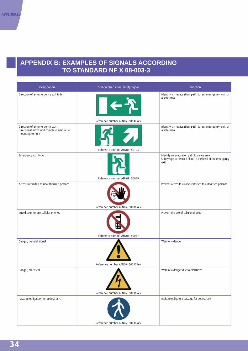
34
APPENDIX B: EXAMPLES OF SIGNALS ACCORDING TO STANDARD NF X 08-003-3
APPENDICES
Designation Standardised visual safety signal Function
Direction of an emergency exit to left
Reference number AFNOR: 50040Rev
Identify an evacuation path to an emergency exit or a safe area
Direction of an emergency exitDirectional arrow and complete silhouette mounting to right
Reference number AFNOR: 50103
Identify an evacuation path to an emergency exit or a safe area
Emergency exit to left
Reference number AFNOR: 50099
Identify an evacuation path to a safe area.Safety sign to be used alone at the level of the emergency exit
Access forbidden to unauthorised persons
Reference number AFNOR: 50006Rev
Prevent access to a zone restricted to authorised persons
Interdiction to use cellular phones
Reference number AFNOR: 50087
Prevent the use of cellular phones
Danger, general signal
Reference number AFNOR: 50017Rev
Warn of a danger
Danger, electrical
Reference number AFNOR: 50016Rev
Warn of a danger due to electricity
Passage obligatory for pedestrians
Reference number AFNOR: 50038Rev
Indicate obligatory passage for pedestrians

35
APPENDIX B: EXAMPLES OF SIGNALS ACCORDING TO STANDARD NF X 08-003-3
The following recommendations have been developed based on works conducted under the ACTEURS project.
C. 1 Information to be provided to users
When the users enter an emergency exit, it is desirable that they find messages tending to reassure them with regard to the place where they are assembled and to give them clear instructions. In the case of direct communication with the exterior, it is desirable that the continuity of information is maintained in the grouping area.
The messages can be designed according to the following priorities:
1. Reassure the users by informing them on the safety of the place where they are assembled and the manner in which the event is being handled, for example:
• The place is sheltered from smoke and fire • The place is under surveillance • Emergency services are on their way • Etc.
2. Give them clear instructions, for example
• Remain in this protected place • Move out following the arrows • Use the emergency telephone • Etc.
C.2 Information for drafting the messages
C.2.1 Use words with positive form
Words with a negative connotation are to be strictly avoided, firstly because they require a more complex cognitive processing and secondly because, in the case of persons not knowing the language (foreigner, illiterate) or persons stressed by their environment, they may be understood wrongly, the opposite of their true meaning.
For example, a person not knowing the language or under stress may not follow the negation of the following phrase “you are not in safety” and therefore believe that he is safe. The wording “you are in danger” on the other hand, is without ambiguity.
The words “do not return to the tunnel” may be replaced with “wait in this protected place”
The phrase “you are out of danger here” may be replaced with “you are safe here.”
C.2.2 Choose a simple and reassuring vocabulary
It is recommended to avoid a technical vocabulary that may not mean much to the users. Thus, it would be better to say “you are in a safe and well ventilated place protected from fire and smoke,” instead of “you are in a pressurised room.”
Simple words should be preferred against a sophisticated vocabulary. “Move out following the arrows” is better than “evacuate following the arrows.”
The indications should leave no room for interpretation. The phrase “rescue services are notified” lacks the information that an active process in progress for getting the users out. “Rescue services are on their way” is a more positive wording that indicates that an action is in progress; it is therefore more reassuring for the waiting users.
C.2.3 Give clear instruction coherent with the organisation in place
Proposing in a shelter to use the emergency phone signifies that there is an organisation in place for answering the calls from waiting users. The absence of response (due for example to an overload on the tunnel operator) may add to the stress and result in a dangerous behaviour to the extent that the persons may think that they are abandoned and forgotten. It is therefore imperative that the instructions or recommendations provided are coherent with actual capacities of the organisation.
APPENDIX C: RECOMMENDATIONS FOR THE LAYOUT OF VISUAL MESSAGES INSTALLED IN EMERGENCY EXITS AND TO THE EXTERIOR

36
C.3 Graphic layout of messages
C.3.1 Colour and shape of visual signals
The NF X 08-003-1 standard specifies the safety identification colours and basic principles for the design of visual safety signals. It thus recommends the use of:
• Yellow colour (and the contrasting black colour) for warning signals meant for drawing the attention to a risk or a danger
• Green colour (with the contrasting white colour) for designing safety signals providing indications for ensuring the safety of persons.
C.3.2 Calligraphy In a language like the French (that contains accents), writing safety messages exclusively in capitals is to be avoided because it makes the message difficult to read. It is thus that in a stressful situation, it is easier to read “You are sheltered from smoke” (“Vous êtes à l'abri des fumées”) rather than “YOU ARE SHELTERED FROM SMOKE” (“VOUS ETES À L'ABRI DES FUMEES”).
Capital letter in the beginning of a sentence and a full stop at its end are essential for a good understanding of the message. However, capitals can also be used for reinforcing the meaning of a word in a message. For example: “In case of fire, you are in DANGER.”
CETU is not in a position at present to propose typefaces to be used. Recommendations can be made only when they are based on in situ experiments remaining to be conducted.
The NF X 08-003-1 standard may be used for defining the size of characters.
APPENDICES

37
APPENDIX D: REGULATION ON TRANSLATION OF MESSAGES
The circular concerning the application, in the transport domains, of the provisions of articles 3 and 4, Law no. 94-665 dated 4 August 1994 relating to the use of French language specifies, in addition to requirements according to law, the permanent and temporary waivers to the obligation of double translation in the domain of international transport, as fixed under the decree no. 98-563 dated 1 July 1998.
The article 3 of the law states that “all inscription or announcement placed or made on the public road, in a place open to public or in a public transport vehicle and meant for the information of public should be formulated in French language.”
The article 4 of the law dated 4 August 1994 imposes on transport carriers or administrators of transport infrastructures that are corporate entities under public law or corporate entities under private law and performing a mission of public service, when they consider it useful, to translate the inscriptions and announcements mentioned in the article 3, in at least two languages.
The obligation of double translation applies to public or private corporate bodies responsible for a public service mission including a part of the activity, by virtue of competency conferred
on them by the law, exercised in transport or operation of transport infrastructures (regions, departments, municipalities and their groups, public establishments attached to them, chambers of commerce and industry, private enterprises administrators of a public transport service, etc.).
The decree dated 1 July 1998 sets out the permanent waivers in situations where the obligation of double translation is inopportune or faces major obstacles. Thus, it is possible to use only one foreign language in addition to French in the following cases:
• For inscriptions or unexpected spot announcements concerning safety or emergency. In these situations where it is essential to deliver the information rapidly, the French language is obviously required, but it is not obligatory when the translation is done to make it into two languages.
• For inscriptions or announcements placed or made on transport infrastructures located in a department close to the frontier, if the only language of translation is that of the country adjoining this department.

38
APPENDICES
APPENDIX E: RESULTS OF EXPERIMENT CONDUCTED IN THE MOULIN TUNNEL (A86)
This Appendix summarises the principal data and conclusions of the experiment conducted in the Moulin tunnel under the management of Inter-departmental Roads Directorate of
Layout diagram of the mock-up in the Moulin Tunnel
E.1 Description of mock-up device
In normal crossing situation In alarm situation
• CE 30a and CE30 b lit above the door and reminder of CE30 pictogram
on the door (regulatory)
• Door painted in green
• Mention “Sortie de secours” (emergency exit) on the door
• Nominal permanent lighting of the door
• Pictogram indicating the direction of opening of the door
• Flashing lights turned off
• Green colour tube surrounding the door
• Floor mat with reminder of CE30 pictogram
• Display of an exit number, easy to identify, for locating oneself in
case of alert via mobile phone
• Activation of alarm siren
• Activation of sound beacons “Attention - Danger – Evacuate here”
• Activation of flashing lights
• Reinforcement of lighting in front of the door
• Activation of luminous chevrons around the exit door, indicating the
direction to follow
E.2 Principal observations of the experiment
• In normal crossing situation
On the whole, the users not informed in advance participating in the experiment perceived the exit doors and recognised their function. On the other hand, the emergency stations, highlighted to a lesser extent were not so well perceived and their function was not recognised. As presented during the experiment, the equipment clearly drawing attention to the exits was well understood by the users as safe place allowing them to evacuate from the tunnel.
• In smoke-filled environment
In an environment with low level of smoke, the static and dynamic devices remain visible.
In thick smoke, the static devices are no longer perceived, the chevrons remain barely visible. The last element visible is the flashing lights that could still be perceived at a distance of 25 m. The sound systems remained audible even when the forced ventilation system was operating.
• During an evacuation in clean environment
The users were placed in a stopped position in the tunnel on board their own vehicle and were confronted with the triggering of all the alarm systems. Globally, all the users had perceived the visual and/or sound devices and had understood their role. The alarm function of the siren was well understood (it signals a danger) as also the function of evacuation induced by other devices. More precisely, the sound beacons give the instruction, the dynamic visual devices (flashing lights and chevrons) indicate where to go. The self-evacuation is initiated by all the visual and sound devices acting together.
Paris Region (DIRIF - Direction Interdépartementale des Routes d'Île-de-France)
Photo of the mock-up

39
APPENDIX F: EXPERIMENTAL PROCEDURE FOR INNOVATIVE DEVICES
More information about innovative devices can be obtained from the following link:www.equipementsdelaroute.developpement-durable.gouv.fr
Innovative devices are being developed constantly. Before use, their advantages have to be evaluated experimentally. For this, the road administrator has to apply to the road safety and traffic delegation (DSCR - Délégation à la sécurité et à la circulation routières) for permission to install the innovative device on his road network. A permission for experimentation is then granted for the selected site.
These authorisations are based on the article 14-1 of the inter-ministerial instruction on road signs for signalling equipment and on the article R119-10 of the roadways code.
The experimental results are then evaluated and if they are favourable, the equipment is authorised for use leading to its generalised installation.
F.1 Which equipment eligible for experimentation ?
When a device whose objective is to equip the roads is not covered by any official text or when it cannot satisfy the conditions of texts concerning it because waivers are required regarding certain points, it is necessary to subject it to an experiment.
F.2 What is the applicable procedure?
The procedure relating to experimentation of road equipment can be divided into six distinct and essential phases. 1. Admissibility of application for experimentation 2. Acceptability of the application for experimentation 3. Authorisation for experimentation 4. Deployment of experimentation 5. Evaluation of experimentation 6. Decision regarding follow-up of experimental results.
After each of these phases, a document is submitted, concluding the phase.
F.3 For more informationThe procedure and the content of a supporting file relating to an application for conducting an experiment and the evaluation protocol can be downloaded from the following address:www.equipementsdelaroute.developpement-durable.gouv.fr (section: experimentation).
F.4 RemarksThe applicant has to bear all financial costs of the experiment.
Details regarding industrial property rights have to be enclosed with the supporting file (certificate stating that the product does not infringe laws regarding industrial property rights and that it is free of all prior rights).

40
APPENDIX G: EXAMPLE OF ALARM DEVICES ACTIVATION SCENARIO
The following diagram proposes an example of the scenario with the activation sequence of devices employed. This chronology, based on the time required for the evacuation of users from a Evènement
Temps disponible pour l'évacuation
Safety margin1’30
T0: Scenario for closedown activated
T0: Triggering of siren + pause + siren
Time for perception,analysis, interpretation3’ minimum
Response time,time for decision foraction 2’ minimum
Time formovement2’ to 4’
Limites des conditionstenables
Time*for detection
Time*for giving alarm
DétectionEvacuation
complète
T0 = basculement
de la situation
End of eventInformation message on radio
T2: Activation of flashing lights and chevrons
T3: Activation of sound beacons in front of exits
T3: Activation of pre-recorded messages on opening of exits
T1: Activation of radio messages (two languages)
* = Operations carried out by the tunnel operating bodyThe time considered includes technological delays for data transmission and delay for human processing11/2008 - Sylvie Lavedrine and Audrey Auboyer based on Model (ISO Draft TC92, 2005)
road tunnel (cf. § 1.3.3 of this document) has to be adapted according to devices available.
APPENDICES

41
NOTES

42
NOTES

43
THE CETU THANKS ALL THOSE WHO HAD PARTICIPATED IN THE
PREPARATION OF THIS DOCUMENT
The members of the “ACTEURS” project team (in particular Frédéric Ricard - ATMB then SFTRF – Project Leader and Alain Noizet, Technical Director), the representatives of Inter-Departmental Roads Directorate of Paris Region - Direction Interdépartementale des Routes d'Île de France (in particular Laurent Baudet), Sylvie Lavedrine, Audrey Auboyer, Laurent Bigou, Marc Tesson (Safety studies - CETU) as well as members of CNESOR who had contributed to the principles retained during the meeting on 5 June 2008.

www.cetu.developpement-durable.gouv.fr
Tunnels study centre25, avenue François Mitterrand
Case n°169674 BRON - FRANCE
Tel. 33 (0)4 72 14 34 00Fax. 33 (0)4 72 14 34 30
[email protected] Desig
n: pe
mac
o - P
rint:
vass
el gr
aphi
que