Embed Size (px)
Citation preview
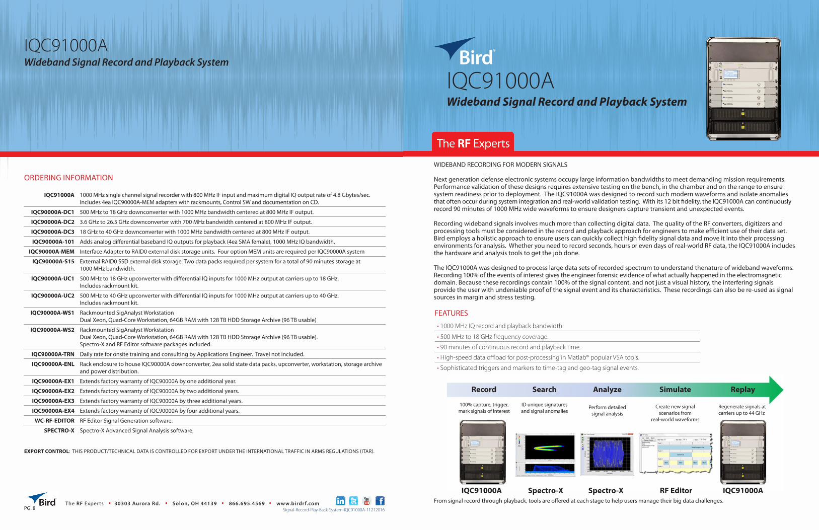
IQC91000A Wideband Signal Record and Playback System
IQC91000A 1000 MHz single channel signal recorder with 800 MHz IF input and maximum digital IQ output rate of 4.8 Gbytes/sec. Includes 4ea IQC90000A-MEM adapters with rackmounts, Control SW and documentation on CD.
IQC90000A-DC1 500 MHz to 18 GHz downconverter with 1000 MHz bandwidth centered at 800 MHz IF output.
IQC90000A-DC2 3.6 GHz to 26.5 GHz downconverter with 700 MHz bandwidth centered at 800 MHz IF output.
IQC90000A-DC3 18 GHz to 40 GHz downconverter with 1000 MHz bandwidth centered at 800 MHz IF output.
IQC90000A-101 Adds analog differential baseband IQ outputs for playback (4ea SMA female), 1000 MHz IQ bandwidth.
IQC90000A-MEM Interface Adapter to RAID0 external disk storage units. Four option MEM units are required per IQC90000A system
IQC90000A-S15 External RAID0 SSD external disk storage. Two data packs required per system for a total of 90 minutes storage at 1000 MHz bandwidth.
IQC90000A-UC1 500 MHz to 18 GHz upconverter with differential IQ inputs for 1000 MHz output at carriers up to 18 GHz. Includes rackmount kit.
IQC90000A-UC2 500 MHz to 40 GHz upconverter with differential IQ inputs for 1000 MHz output at carriers up to 40 GHz. Includes rackmount kit.
IQC90000A-WS1 Rackmounted SigAnalyst WorkstationDual Xeon, Quad-Core Workstation, 64GB RAM with 128 TB HDD Storage Archive (96 TB usable)
IQC90000A-WS2 Rackmounted SigAnalyst WorkstationDual Xeon, Quad-Core Workstation, 64GB RAM with 128 TB HDD Storage Archive (96 TB usable). Spectro-X and RF Editor software packages included.
IQC90000A-TRN Daily rate for onsite training and consulting by Applications Engineer. Travel not included.
IQC90000A-ENL Rack enclosure to house IQC90000A downconverter, 2ea solid state data packs, upconverter, workstation, storage archive and power distribution.
IQC90000A-EX1 Extends factory warranty of IQC90000A by one additional year.
IQC90000A-EX2 Extends factory warranty of IQC90000A by two additional years.
IQC90000A-EX3 Extends factory warranty of IQC90000A by three additional years.
IQC90000A-EX4 Extends factory warranty of IQC90000A by four additional years.
WC-RF-EDITOR RF Editor Signal Generation software.
SPECTRO-X Spectro-X Advanced Signal Analysis software.
ORDERING INFORMATION
The RF Experts • 30303 Aurora Rd. • Solon, OH 44139 • 866.695.4569 • www.birdrf.comSignal-Record-Play-Back-System-IQC91000A-11212016
IQC91000A ®
Wideband Signal Record and Playback System
• 1000 MHz IQ record and playback bandwidth.
• 500 MHz to 18 GHz frequency coverage.
• 90 minutes of continuous record and playback time.
• High-speed data offload for post-processing in Matlab® popular VSA tools.
• Sophisticated triggers and markers to time-tag and geo-tag signal events.
FEATURES
WIDEBAND RECORDING FOR MODERN SIGNALS
Next generation defense electronic systems occupy large information bandwidths to meet demanding mission requirements. Performance validation of these designs requires extensive testing on the bench, in the chamber and on the range to ensure system readiness prior to deployment. The IQC91000A was designed to record such modern waveforms and isolate anomalies that often occur during system integration and real-world validation testing. With its 12 bit fidelity, the IQC91000A can continuously record 90 minutes of 1000 MHz wide waveforms to ensure designers capture transient and unexpected events.
Recording wideband signals involves much more than collecting digital data. The quality of the RF converters, digitizers and processing tools must be considered in the record and playback approach for engineers to make efficient use of their data set. Bird employs a holistic approach to ensure users can quickly collect high fidelity signal data and move it into their processing environments for analysis. Whether you need to record seconds, hours or even days of real-world RF data, the IQC91000A includes the hardware and analysis tools to get the job done.
The IQC91000A was designed to process large data sets of recorded spectrum to understand thenature of wideband waveforms. Recording 100% of the events of interest gives the engineer forensic evidence of what actually happened in the electromagnetic domain. Because these recordings contain 100% of the signal content, and not just a visual history, the interfering signals provide the user with undeniable proof of the signal event and its characteristics. These recordings can also be re-used as signal sources in margin and stress testing.
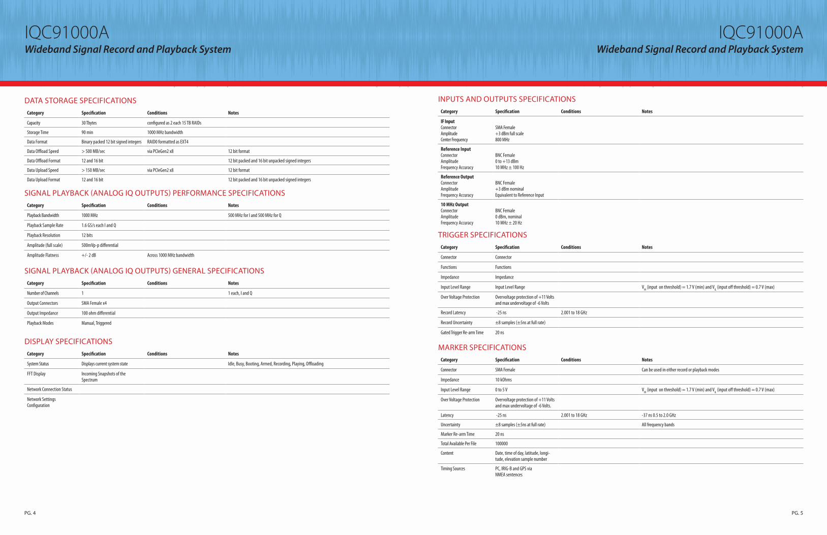
Record Search Analyze Simulate Replay
Regenerate signals at carriers up to 44 GHz
Create new signal scenarios from
real-world waveforms
Perform detailedsignal analysis
ID unique signatures and signal anomalies
100% capture, trigger, mark signals of interest
IQC91000A Spectro-X Spectro-X RF Editor IQC91000AFrom signal record through playback, tools are offered at each stage to help users manage their big data challenges.
EXPORT CONTROL: THIS PRODUCT/TECHNICAL DATA IS CONTROLLED FOR EXPORT UNDER THE INTERNATIONAL TRAFFIC IN ARMS REGULATIONS (ITAR).
PG. 8

IQC91000A Wideband Signal Record and Playback System
TURNING DATA INTO INFORMATION
IQC91000AWideband Signal Record and Playback System
Category Specification Conditions Notes
Center Frequency Tuning Range 500 MHz to18 GHz
Frequency Tuning Resolution 1 MHz
Maximum Record Bandwidth 1000 MHz at 4 dB BW Decimated record bandwidths at 500 MHz, 250 MHz and 125 MHz
Record Sample Rate 3.2 GS/s 1.6 GS/s for I and 1.6 GS/s for Q
Record Resolution 12 bits
Gain Adjustment Range 0 to 30 dB
Gain Adjustment Resolution 1.0 dB
Full-scale Amplitude +3 dBm Input signal + Gain To avoid clipping, (Input signal amplitude + gain) ≤ +3 dBm
Amplitude Limiting +10 dBm Input signal + Gain To avoid damage to the system, an internal switch will open if (Input signal amplitude + gain) ≥ +10 dBm
Input 1 dB Compression Point > 0 dBm When configured with a gain of +15 dB Note that this is above the (Input signal amplitude + gain) limiting value of +10 dBm
Third Order Intercept Point > +10 dBm When configured with a gain of +15 dB
Amplitude Flatness +/- 2.3 dB Across 1000 MHz bandwidth
Displayed Average Noise Level -158 dBm/Hz @ 1 GHz center frequency with 30 dB gain applied
Displayed Average Noise Level -160 dBm/Hz @ 4 GHz center frequency with 30 dB gain applied
Displayed Average Noise Level -155 dBm/Hz @ 10 GHz center frequency with 30 dB gain applied
Displayed Average Noise Level -155 dBm/Hz @ 16 GHz center frequency with 30 dB gain applied
Spurious Free Dynamic Range > 50 dB 500 MHz to 18 GHz with 0 dB gain applied
Noise Figure 13 dB 500 MHz to 7.9 GHz, 10.101 GHz to 17.499 GHz with 30 dB gain applied
Noise Figure 14 dB 7.901 GHz to 10.1 GHz with 30 dB gain applied
Noise Figure 16 dB 17.5 to 18.5 GHz with 30 dB gain applied
SSB Phase Noise -65 dBc/Hz @ 100 Hz offset When measured with a gain of 30 dB and an input signal level of -10 dBm. Specifications valid for all center frequency tuning ranges
SSB Phase Noise -90 dBc/Hz @ 1 kHz offset When measured with a gain of 30 dB and an input signal level of -10 dBm. Specifications valid for all center frequency tuning ranges
SSB Phase Noise -100 dBc/Hz @ 10 kHz offset When measured with a gain of 30 dB and an input signal level of -10 dBm. Specifications valid for all center frequency tuning ranges
SSB Phase Noise -105 dBc/Hz @ 100 kHz offset When measured with a gain of 30 dB and an input signal level of -10 dBm. Specifications valid for all center frequency tuning ranges
SSB Phase Noise -111 dBc/Hz @ 1 MHz offset When measured with a gain of 30 dB and an input signal level of -10 dBm. Specifications valid for all center frequency tuning ranges
SSB Phase Noise -130 dBc/Hz ≥ 10 MHz offset When measured with a gain of 30 dB and an input signal level of -10 dBm. Specifications valid for all center frequency tuning ranges
High-speed recording systems create vast amounts of IQ data. Spectro-X can accelerate your time-to-insight by rapidly characterizing emitters and generating PDWs with its built-in search tools. For MATLAB® users, our Class Definition allows you to efficiently process blocks of IQ data and metadata without having to load the entire recording into the computing environment.
100% signal capture means users can identify design issues such as LO feedthrough, image responses and switching transients as shown in this photo.
Spectro-X includes four search engines for locating and characterizing signals of interest. Shown here are the results of a Pulse Search with each of the PDWs computed along with the Spectrogram plot of each result
SYSTEM FRIENDLY INTERFACESThe complexity of modern defense systems demands that test equipment integrate well into the test environment to verify performance under all modes of operation. This is especially true during early design phases where test equipment must act as surrogate prior to actual hardware availability. The IQC91000A is designed to integrate into your test environment to record both metadata along with IQ data during system tests. This includes triggers to initiate and terminate recordings plus markers to time-tag and geo-tag signal events of interest. The PCIe Gen2 x8 interface allows rapid offload of recordings so you can begin post-processing in Matlab® and other popular VSA tools.
Monitor spectrum events while recording
Configure network and instrument settingsDifferential IQ outputs for vector
upconversion
Synchronize operation with other system events Correlate data to IRIG-Band GPS time and location
Cabled PCIe interface for high speed offload to
workstation
IF Input from X-COM or 3rd party converters
COMPATIBILITY WITH THIRD PARTY CONVERTERSThe IQC91000A comes standard with a microwave down converter to cover 500 MHz to 18 GHz, however, the system is compatible with any converter that can produce an 800 MHz IF such as the Keysight® X-Series signal analyzers for downconversion of signals up to 50 GHz. Replay of high fidelity recordings is accomplished via industry-leading microwave upconverters such as the vector signal generators from Keysight Technologies® (E8267D) and Rohde & Schwarz® (SMW200A). These products offer streaming RF upconversion via their wideband IQ inputs to replay recordings at carriers at 20 GHz and beyond.
SIGNAL RECORD PERFORMANCE SPECIFICATIONSThe following specifications pertain to the IQC91000A record and playback system. Each system consists of the following elements: 1ea IQC91000A, 1ea IQC90000A-101, 1ea IQC90000A-DC1, 4ea IQC90000A-MEM and 2ea IQC90000A-S15 units. All specifications are nominal values that are representative of expected performance. Some variation may exist from system to system.
SIGNAL RECORD GENERAL SPECIFICATIONSCategory Specification Conditions
Number of Record Channels 1 ≥ 10 MHz offset
Input Connector SMA Female x1 ≥ 10 MHz offset
Input Impedance 50 ohms ≥ 10 MHz offset
Input VSWR < 2.5 : 1 ≥ 10 MHz offset
Record Modes ManualTimedTriggeredTime Of DayGated Record
Software/API Start and Stop,Supports both sample count and time in seconds, minutes and hours2 Trigger Ports with rising or falling edge, boolean AND/OR logicStart on Time of Day (System Clock)Record only when Gate is High or Low
PG. 3PG. 2
IQC91000A Wideband Signal Record and Playback System
IQC91000AWideband Signal Record and Playback System
Category Specification Conditions Notes
Capacity 30 Tbytes configured as 2 each 15 TB RAIDs
Storage Time 90 min 1000 MHz bandwidth
Data Format Binary packed 12 bit signed integers RAID0 formatted as EXT4
Data Offload Speed > 500 MB/sec via PCIeGen2 x8 12 bit format
Data Offload Format 12 and 16 bit 12 bit packed and 16 bit unpacked signed integers
Data Upload Speed > 150 MB/sec via PCIeGen2 x8 12 bit format
Data Upload Format 12 and 16 bit 12 bit packed and 16 bit unpacked signed integers
DATA STORAGE SPECIFICATIONS
Category Specification Conditions Notes
Playback Bandwidth 1000 MHz 500 MHz for I and 500 MHz for Q
Playback Sample Rate 1.6 GS/s each I and Q
Playback Resolution 12 bits
Amplitude (full scale) 500mVp-p differential
Amplitude Flatness +/- 2 dB Across 1000 MHz bandwidth
SIGNAL PLAYBACK (ANALOG IQ OUTPUTS) PERFORMANCE SPECIFICATIONS
Category Specification Conditions Notes
Number of Channels 1 1 each, I and Q
Output Connectors SMA Female x4
Output Impedance 100 ohm differential
Playback Modes Manual, Triggered
SIGNAL PLAYBACK (ANALOG IQ OUTPUTS) GENERAL SPECIFICATIONS
Category Specification Conditions Notes
System Status Displays current system state Idle, Busy, Booting, Armed, Recording, Playing, Offloading
FFT Display Incoming Snapshots of the Spectrum
Network Connection Status
Network Settings Configuration
DISPLAY SPECIFICATIONS
Category Specification Conditions Notes
IF InputConnectorAmplitudeCenter Frequency
SMA Female+3 dBm full scale800 MHz
Reference InputConnectorAmplitudeFrequency Accuracy
BNC Female0 to +13 dBm10 MHz ± 100 Hz
Reference Output ConnectorAmplitudeFrequency Accuracy
BNC Female+3 dBm nominalEquivalent to Reference Input
10 MHz Output ConnectorAmplitudeFrequency Accuracy
BNC Female0 dBm, nominal10 MHz ± 20 Hz
INPUTS AND OUTPUTS SPECIFICATIONS
Category Specification Conditions Notes
Connector Connector
Functions Functions
Impedance Impedance
Input Level Range Input Level Range VIH (input on threshold) = 1.7 V (min) and VIL (input off threshold) = 0.7 V (max)
Over Voltage Protection Overvoltage protection of +11 Volts and max undervoltage of -6 Volts
Record Latency -25 ns 2.001 to 18 GHz
Record Uncertainty ±8 samples (±5ns at full rate)
Gated Trigger Re-arm Time 20 ns
TRIGGER SPECIFICATIONS
Category Specification Conditions Notes
Connector SMA Female Can be used in either record or playback modes
Impedance 10 kOhms
Input Level Range 0 to 5 V VIH (input on threshold) = 1.7 V (min) and VIL (input off threshold) = 0.7 V (max)
Over Voltage Protection Overvoltage protection of +11 Voltsand max undervoltage of -6 Volts.
Latency -25 ns 2.001 to 18 GHz -37 ns 0.5 to 2.0 GHz
Uncertainty ±8 samples (±5ns at full rate) All frequency bands
Marker Re-arm Time 20 ns
Total Available Per File 100000
Content Date, time of day, latitude, longi-tude, elevation sample number
Timing Sources PC, IRIG-B and GPS via NMEA sentences
MARKER SPECIFICATIONS
PG. 4 PG. 5

IQC91000A Wideband Signal Record and Playback System
IQC91000AWideband Signal Record and Playback System
Category Specification Conditions Notes
Connector BNC Female Can be used in either record or playback modes
Standard IRIG-B122
Voltage Levels Amplitude modulated, 3 Vpp, sine wave carrier
Over Voltage Protection Overvoltage protection of +11 Volts and max undervoltage of -6 Volts.
IRIG SPECIFICATIONS
Category Specification Conditions Notes
Connector 9 pin D Female Can be used in either record or playback modes
Speed 4800 and 9600 baud
Supported Sentences GPGGA, GPVTG, GPZDA
Protocol ASCII, 8-bit data, one start and one stop bit, no parity
GPS NMEA SPECIFICATIONS
Category Specification Conditions Notes
System Requirements (minimum)
Windows 7, 64 bit, 8 GB RAM
System Requirements (recommended)
Option IQC90000A-WS1: Rackmounted SigAnalyst WorkstationDual Xeon, Quad-Core Workstation, 64GB RAM with 128 TB HDD Storage Archive (96 TB usable). RAID60.
Communication Interface Standard
LAN TCP/IP Interface
Communication Interface Speed
1000Base-T
Communication Interface Connector
RJ45 Ethertwist
System Re-Arm Time 4 Seconds (without markers) from the graphical user interface
faster using API commands
SYSTEM CONTROL SPECIFICATIONS
Category Specification Conditions Notes
Trigger timing uncertainty between any two IQC91000A systems
±7.8ns Same 10 MHz reference and trigger signals must be applied to all IQC91000A systems
SYSTEM SYNCHRONIZATION SPECIFICATIONS
Category Specification Conditions Notes
System Warm Up Time 30 minutes Can be used in either record or playback modes
Operating Temperature Range 0 to 35 °C
Storage Temperature Range -20 to +70 °C
Altitude Max 2000m above sea level
Humidity Max 80% non-condensing
PHYSICAL SPECIFICATIONS
Category Specification Conditions Notes
IQC91000A 3.5" H x 16.5" W x 19.5" D Can be used in either record or playback modes
option IQC90000A-DC1 1.75" H x 16.75" W x 23" D
option IQC90000A-MEM 1.75" H x 12" W x 10.5" D
option IQC90000A-S15 3.5” H x 16.5” W x 17.75” D
option IQC90000A-UC1 7" H x 16.8" W x 20.3" D
DIMENSIONS SPECIFICATIONS
Category Specification Conditions Notes
IQC91000A 100/120 or 220/240 VAC, 50/60 Hz, 400 W maximum
option IQC90000A-DC1 100/120 or 220/240 VAC, 50/60 Hz, 150 W maximum
option IQC90000A-MEM 100/120 or 220/240 VAC, 50/60 Hz, 72 W maximum for each unit
four each option -MEM units are required per system
option IQC90000A-S15 100/120 or 220/240 VAC, 50/60 Hz, 130 W maximum
two each option -S15 units are required per system
option IQC90000A-UC1 100/120 or 220/240 VAC, 50/60 Hz, 650 W maximum
POWER SPECIFICATIONS
Category Specification Conditions Notes
IQC91000A 22 lbs.
option IQC90000A-DC1 25 lbs.
option IQC90000A-MEM 5 lbs. for each unit four each option -MEM units are required per system
option IQC90000A-S15 14 lbs. for each unit two each option -S15 units are required per system
option IQC90000A-UC1 54 lbs.
WEIGHT SPECIFICATIONS
Category Specification Conditions Notes
IQC91000A System Compliant with test methods aligned with IEC 60068-2 and have humidity, shock, vibration, altitude, and power line condition levels similar to MIL-PRF-28800F Class 3.
ENVIRONMENTAL SPECIFICATIONS
PG. 7PG. 6


![From the Observation of UHECR Radio Signal in [1-200] MHz](https://img.pdfslide.us/doc/110x75/61a67c1e24162e255125b444/from-the-observation-of-uhecr-radio-signal-in-1-200-mhz-.jpg)