Embed Size (px)
Citation preview
ARTICLE IN PRESS
Contents lists available at ScienceDirect
Signal Processing
Signal Processing 89 (2009) 1162–1175
0165-16
doi:10.1
� Cor
E-m
(H.-L. Y
journal homepage: www.elsevier.com/locate/sigpro
Multirate adaptive filtering for low complexity DS/CDMAcode acquisition
Hua-Lung Yang �, Wen-Rong Wu
Department of Communication Engineering, National Chiao-Tung University, Hsin Chu 300, Taiwan, ROC
a r t i c l e i n f o
Article history:
Received 1 June 2008
Received in revised form
27 October 2008
Accepted 27 December 2008Available online 10 January 2009
Keywords:
Code acquisition
Low complexity
Adaptive filtering
Multirate signal processing
DS/CDMA
84/$ - see front matter & 2009 Elsevier B.V. A
016/j.sigpro.2008.12.024
responding author. Tel.: +886 35731647.
ail addresses: [email protected], aquari
ang), [email protected] (W.-R. Wu).
a b s t r a c t
Code acquisition in CDMA systems is conventionally conducted with a matched-filter
based structure. However, the performance of this method degrades greatly while
multiple access interference presents. Recently, an adaptive filtering scheme was
proposed to solve this problem. It has been shown that the computational complexity of
this approach is proportional to the delay uncertainty and inversely proportional to the
required acquisition time. When propagation delay is large and the required acquisition
time is short, the computational complexity of the adaptive filtering approach will
become high. In this paper, we propose a multirate adaptive code acquisition approach
to alleviate this problem. The proposed scheme is comprised of several acquisition units
operating in different processing rates. Thanks to the decimation property in multirate
processing, the overall computational complexity can be greatly reduced. Theoretical
analysis of adaptive filters and mean acquisition time is also provided. Experimental
results show that while the proposed scheme can have comparable performance with
respect to the original adaptive acquisition scheme, its computational complexity is
much lower.
& 2009 Elsevier B.V. All rights reserved.
1. Introduction
Code-division multiple access (CDMA) is a promisingtechnique for wireless mobile communication. It is wellknown that the main performance bottleneck for a CDMAsystem is the multiple access interference (MAI). MAI notonly affects detection, but also code synchronization. Codesynchronization can be further divided into code acquisi-tion and code tracking. In this paper, we consider codeacquisition with MAI. Code acquisition has been widelystudied in the literature. The conventional approach tothis problem is the well-known matched-filter (MF) basedmethod [1–10,32,36] (and references therein). The MF canhave a serial [1], parallel [2–4], or hybrid search structure
ll rights reserved.
providing an easy trade-off between hardware complexityand acquisition time. However, the MF-based method isonly optimal for the single-user case. The acquisitionperformance degrades greatly when MAI presents, espe-cially in near–far environments [5,6]. To evaluate theperformance of an acquisition scheme, a measure calledacquisition-based capacity was defined in [7]. Thiscapacity corresponds to the maximum number of usersthat a system can serve (with certain acquisition perfor-mance). It was shown in [7,19] that the asymptoticacquisition-based capacity for the MF is L=½2 lnðLÞ�, whereL is the processing gain. The quantity is less than the bit-error-rate-based capacity [8] which is proportional toL. This implies that code acquisition may become alimiting factor for a CDMA system capacity. Anotherdiscussion on the acquisition-based capacity for the MFcan be found in [9].
Another category of the acquisition technique qem-ploys subspace- or matrix-based methods [11–18]. The
ARTICLE IN PRESS
LMS
adaptivefilter
Store results
Mc-tap
r (n)
x1 (n-qMc)
e (n)
+ -
user-1's PNsequence
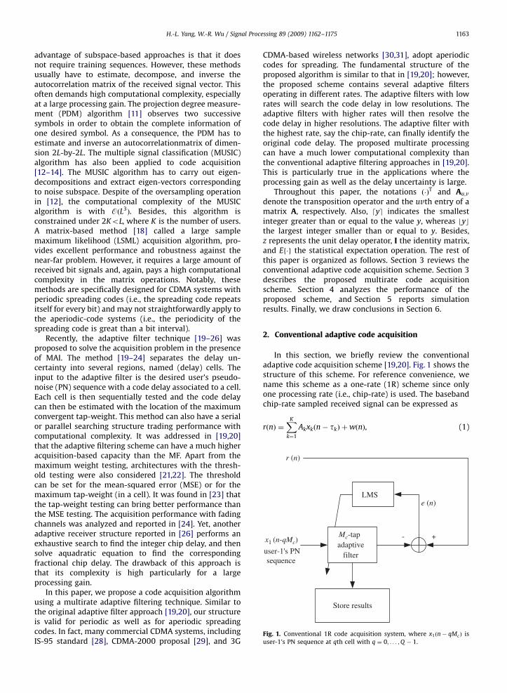
Fig. 1. Conventional 1R code acquisition system, where x1ðn� qMcÞ is
user-1’s PN sequence at qth cell with q ¼ 0; . . . ;Q � 1.
H.-L. Yang, W.-R. Wu / Signal Processing 89 (2009) 1162–1175 1163
advantage of subspace-based approaches is that it doesnot require training sequences. However, these methodsusually have to estimate, decompose, and inverse theautocorrelation matrix of the received signal vector. Thisoften demands high computational complexity, especiallyat a large processing gain. The projection degree measure-ment (PDM) algorithm [11] observes two successivesymbols in order to obtain the complete information ofone desired symbol. As a consequence, the PDM has toestimate and inverse an autocorrelationmatrix of dimen-sion 2L-by-2L. The multiple signal classification (MUSIC)algorithm has also been applied to code acquisition[12–14]. The MUSIC algorithm has to carry out eigen-decompositions and extract eigen-vectors correspondingto noise subspace. Despite of the oversampling operationin [12], the computational complexity of the MUSICalgorithm is with OðL3
Þ. Besides, this algorithm isconstrained under 2KoL, where K is the number of users.A matrix-based method [18] called a large samplemaximum likelihood (LSML) acquisition algorithm, pro-vides excellent performance and robustness against thenear-far problem. However, it requires a large amount ofreceived bit signals and, again, pays a high computationalcomplexity in the matrix operations. Notably, thesemethods are specifically designed for CDMA systems withperiodic spreading codes (i.e., the spreading code repeatsitself for every bit) and may not straightforwardly apply tothe aperiodic-code systems (i.e., the periodicity of thespreading code is great than a bit interval).
Recently, the adaptive filter technique [19–26] wasproposed to solve the acquisition problem in the presenceof MAI. The method [19–24] separates the delay un-certainty into several regions, named (delay) cells. Theinput to the adaptive filter is the desired user’s pseudo-noise (PN) sequence with a code delay associated to a cell.Each cell is then sequentially tested and the code delaycan then be estimated with the location of the maximumconvergent tap-weight. This method can also have a serialor parallel searching structure trading performance withcomputational complexity. It was addressed in [19,20]that the adaptive filtering scheme can have a much higheracquisition-based capacity than the MF. Apart from themaximum weight testing, architectures with the thresh-old testing were also considered [21,22]. The thresholdcan be set for the mean-squared error (MSE) or for themaximum tap-weight (in a cell). It was found in [23] thatthe tap-weight testing can bring better performance thanthe MSE testing. The acquisition performance with fadingchannels was analyzed and reported in [24]. Yet, anotheradaptive receiver structure reported in [26] performs anexhaustive search to find the integer chip delay, and thensolve aquadratic equation to find the correspondingfractional chip delay. The drawback of this approach isthat its complexity is high particularly for a largeprocessing gain.
In this paper, we propose a code acquisition algorithmusing a multirate adaptive filtering technique. Similar tothe original adaptive filter approach [19,20], our structureis valid for periodic as well as for aperiodic spreadingcodes. In fact, many commercial CDMA systems, includingIS-95 standard [28], CDMA-2000 proposal [29], and 3G
CDMA-based wireless networks [30,31], adopt aperiodiccodes for spreading. The fundamental structure of theproposed algorithm is similar to that in [19,20]; however,the proposed scheme contains several adaptive filtersoperating in different rates. The adaptive filters with lowrates will search the code delay in low resolutions. Theadaptive filters with higher rates will then resolve thecode delay in higher resolutions. The adaptive filter withthe highest rate, say the chip-rate, can finally identify theoriginal code delay. The proposed multirate processingcan have a much lower computational complexity thanthe conventional adaptive filtering approaches in [19,20].This is particularly true in the applications where theprocessing gain as well as the delay uncertainty is large.
Throughout this paper, the notations ð�ÞT and Au;v
denote the transposition operator and the uvth entry of amatrix A, respectively. Also, dye indicates the smallestinteger greater than or equal to the value y, whereas bycthe largest integer smaller than or equal to y. Besides,z represents the unit delay operator, I the identity matrix,and Ef�g the statistical expectation operation. The rest ofthis paper is organized as follows. Section 3 reviews theconventional adaptive code acquisition scheme. Section 3describes the proposed multirate code acquisitionscheme. Section 4 analyzes the performance of theproposed scheme, and Section 5 reports simulationresults. Finally, we draw conclusions in Section 6.
2. Conventional adaptive code acquisition
In this section, we briefly review the conventionaladaptive code acquisition scheme [19,20]. Fig. 1 shows thestructure of this scheme. For reference convenience, wename this scheme as a one-rate (1R) scheme since onlyone processing rate (i.e., chip-rate) is used. The basebandchip-rate sampled received signal can be expressed as
rðnÞ ¼XK
k¼1
Akxkðn� tkÞ þwðnÞ, (1)
ARTICLE IN PRESS
H.-L. Yang, W.-R. Wu / Signal Processing 89 (2009) 1162–11751164
where K , tk, Ak, xkðnÞ, and wðnÞ denotes the number ofuser, the code delay, the signal amplitude, the transmittedsignal of user-k, and channel noise, respectively. Thechannel noise is assumed to be additive white Gaussianand its mean is zero. The transmitted signal of user-k canbe expressed as
xkðnÞ ¼X1
j¼�1
dkðjÞXL�1
l¼0
ck;jðlÞpðn� l� jLÞ; k ¼ 1; . . . ;K , (2)
where dkðjÞ denotes the jth BPSK signal of user-k andck;jðlÞ 2 f1;�1g corresponds to the lth chip signal in dkðjÞ.Also, L denotes the processing gain and pðnÞ the chip-ratesampled pulse. Before proceed further, we list assump-tions to be used in the sequel:
(a)
User-1’s code delay is of interest and A1 ¼ 1. (b) The code delay is an integer multiples of the chip-duration and smaller than L.
(c) Carrier synchronization is established before codeacquisition.
(d) No data are modulated for user-1’s signal in the periodof code acquisition, i.e., d1ðjÞ ¼ 1.
(e) The chip-pulse is considered as a rectangular pulsewith unit amplitude.
(f) The code sequence ck;j has a period much higher thanthe processing gain such that the input to the adaptivefilter can be viewed as statistically white.
(g)
Only the additive white Gaussian noise (AWGN)channel is considered and the summation of MAIand white Gaussian noise can be modeled as anotherwhite Gaussian noise [32].The 1R scheme first divides L into Q ¼ dL=Mce cells,where Mc is the length of the adaptive filter. The adaptivefilter then serially searches the code delay in these cells.The least-mean-square (LMS) algorithm is employed tominimize the MSE between the received signal rðnÞ andthe adaptive filter output (see Fig. 1). The tap-weightupdate equations are given by
wqðnþ 1Þ ¼ wqðnÞ þ mceðnÞxqðnÞ, (3)
eðnÞ ¼ rðnÞ � ½wqðnÞ�TxqðnÞ; q 2 f0; . . . ;Q � 1g, (4)
where mc denotes the step size controlling the conver-gence of the adaptive filter, wqðnÞ ¼ ½wq
0ðnÞ;wq1ðnÞ; . . . ;
wqMc�1ðnÞ�
T the filter tap-weight vector for the qth cell,and xqðnÞ ¼ ½x1ðn� qMcÞ; x1ðn� qMc � 1Þ; . . . ; x1ðn� qMc �
Mc þ 1Þ�T the corresponding input vector. Here, q issequentially increased from zero to Q � 1. The tap-weightvector wqðnÞ for a particular q is stored after someiterations, say N1 chips. Then, an estimation of t1 can bederived with the tap-index of the maximum tap-weight(among all cells). Let the Dcth tap (0pDcoMc) of theadaptive filter in the acth cell has the maximum value.Then, we can have the delay estimation t1 ¼ acMc þ Dc .Combine wqðN1Þ, q ¼ 0;1; . . . ;Q � 1 into a big vector w,i.e., w ¼ ½½w0ðN1Þ�
T; ½w1ðN1Þ�T; . . . ; ½wQ�1ðN1Þ�
T�T. It can beshown that the probability of acquisition error is
Pe ¼ 1� PbðwcXwjÞ; caj; fc; jg 2 f0;1; . . . ; L� 1g, (5)
where wj denotes the jth element of w and wc the tap-weight corresponding to the true code delay t1 (i.e.,c ¼ t1). To evaluate (5), we need to know the stochasticproperties of the tap-weights. It has been shown in [33]that these tap-weights at convergence have Gaussiandistributions with a mean vector of
mðL�1Þ ¼ wo, (6)
and a covariance matrix of
CðL�LÞ �mc
2JminI (7)
9s2wI, (8)
where wo is the optimum solution of w solved withthe Wiener equations [34], Jmin is the correspondingminimum mean-squared error (MMSE), and s2
w is thevariance of each tap-weight. Let Rq
¼ EfxqðnÞ½xqðnÞ�Tg andpq ¼ EfxqðnÞrðnÞg. Since the input is white, Rq
¼ IMc�Mc. It is
well known that wqo ¼ ðR
qÞ�1pq. Let t1 ¼ acMc þDc ,
0pDcoMc , and pqj is the jth entry of pq (j 2 f0;1; . . . ;
Mc � 1g). It is simple to show that pqj ¼ 1 when q ¼ ac and
j ¼ Dc , and pqj ¼ 0 otherwise. This is to say that a unique
peak with value one will appear in wc , and all otherweights are zeros. Thus, we can have Jmin ¼ Efr2ðnÞg � 1.Using Eqs. (6) and (8), we can rewrite (5) as
Pe ¼ 1�
Z 1�1
1� Qwc
sw
� �� �L�1
exp �ðwc � 1Þ2
2s2w
!dwc , (9)
where Q ð�Þ denotes the Q-function [35]. It is known thatan Mc-tap adaptive filter (with the LMS algorithm)requires 2Mc multiplications per iteration. Thus, thecomputational complexity is proportional to the filter size.
3. Proposed adaptive multirate code acquisition
To understand our idea easier, we start our develop-ment with a two-rate (2R) system. Then, we will extend itto a three-rate (3R) system.
3.1. 2R scheme
Following the assumptions given in Section 2, weexpress (1) as
rðnÞ ¼XK
k¼1
Akxkðn� tkÞ þwðnÞ
¼ x1ðn� t1Þ þ vðnÞ, (10)
where
vðnÞ ¼XK
k¼2
Akxkðn� tkÞ þwðnÞ (11)
denotes the sum of MAI and white Gaussian noise. Let thevariance of vðnÞ be s2
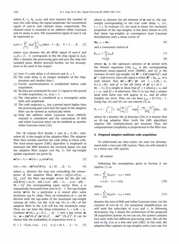
v. For notational simplification, wewill omit the subscripts of x1ðnÞ and t1 in followingderivations. Fig. 2 shows the architecture of the proposed2R acquisition system. As we can see, the system containstwo units with two different processing rates. We call theunit in Fig. 2(a) as a low-rate unit (LRU). In this unit, theadaptive filter updates its tap-weights with a low rate. For
ARTICLE IN PRESS
LMS
LMS
Find
ˆ
Find
Δ
( )LPFx n ( )L mx
ˆz−Δ
( )nx ˆDz− ( )H nw
( )L mw
( )LPFr n
( )r n
( )r n
( )H nx
adjust at every m instant
+-
- +
( )Lr mLPFPTF
DLf
D
( )nx LRAF
HRAF
LPFLf
DTF
�
�
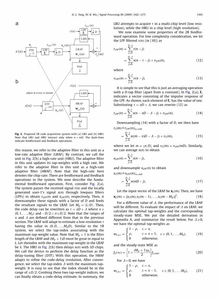
Fig. 2. Proposed 2R code acquisition system with (a) LRU and (b) HRU.
Note that LRU and HRU interact only when n ¼ mD. The dash-lines
indicate feedforward and feedback operations.
H.-L. Yang, W.-R. Wu / Signal Processing 89 (2009) 1162–1175 1165
this reason, we refer to the adaptive filter in this unit as alow-rate adaptive filter (LRAF). By contrast, we call theunit in Fig. 2(b) a high-rate unit (HRU). The adaptive filterin this unit updates its tap-weights with a high rate. Werefer to the adaptive filter in this unit as a high-rateadaptive filter (HRAF). Note that the high-rate heredenotes the chip-rate. There are feedforward and feedbackoperations in the system. We now describe the funda-mental feedforward operation. First, consider Fig. 2(a).The system passes the received signal rðnÞ and the locallygenerated user-1’s signal xðnÞ through lowpass filters(LPFs) to obtain rLPFðnÞ and xLPFðnÞ, respectively. Then, itdownsamples these signals with a factor of D and feedsthe resultant signals to the LRAF. Let Mp ¼ dL=De. Then,the code delay can be rewritten as t ¼ aDþ D where a 2f0;1; . . . ;Mpg and �D=2oDpD=2. Note that the ranges ofa and D are defined different from that in the previoussection. The LRAF will adapt to estimate a low-resolution thaving the value in f0;D; . . . ;MpDg. Similar to the 1Rsystem, we select the tap-index associating with themaximum tap-weight value. Note that Mp þ 1 is the filterlength of the LRAF and ðMp þ 1ÞD must be great or equal toL. Let theindex with the maximum tap-weight in the LRAFbe a. The HRU in Fig. 2(b) then delays xðnÞ with aD chips.We call the device to perform the delay function as thedelay-tuning filter (DTF). With this operation, the HRAFadapts to refine the code-delay resolution. After conver-gence, we select the tap-index D with the maximum tap-weight. It is easy to see that the index should be in therange of �D=2. Combing these two tap-weight indices, wecan finally obtain a code-delay estimate. In summary, the
LRU attempts to acquire t in a multi-chip level (low reso-lution), while the HRU in a chip level (high resolution).
We now examine some properties of the 2R feedfor-ward operation. For low complexity consideration, we letthe LPF filtered rðnÞ (in (10)) as
rLPF ðnÞ ¼XD�1
j¼0
rðn� jÞ
¼XD�1
j¼0
xðn� t� jÞ þ vLPFðnÞ, (12)
where
vLPFðnÞ ¼XD�1
j¼0
vðn� jÞ. (13)
It is simple to see that this is just an averaging operationwith a D-tap filter (apart from a constant). In Fig. 2(a), fL
indicates a vector consisting of the impulse response ofthe LPF. As shown, each element of fL has the value of one.Substituting t ¼ aDþD, we can rewrite (12) as
rLPF ðnÞ ¼XD�1
j¼0
xðn� aD�D� jÞ þ vLPF ðnÞ. (14)
Downsampling (14) with a factor of D, we then have
rLðmÞ9rLPFðnÞjn¼mD
¼XD�1
j¼0
xððm� aÞD� D� jÞ þ vLðmÞ, (15)
where we let m ¼ bn=Dc and vLðmÞ ¼ vLPF ðmDÞ. Similarly,we can average xðnÞ to obtain
xLPF ðnÞ ¼XD�1
j¼0
xðn� jÞ, (16)
and downsample xLPFðnÞ to obtain
xLðmÞ9xLPF ðnÞjn¼mD
¼XD�1
j¼0
xðmD� jÞ. (17)
Let the input vector of the LRAF be xLðmÞ. Then, we have
xLðmÞ ¼ ½xLðmÞ; xLðm� 1Þ; . . . ; xLðm�MpÞ�T. (18)
For a different value of D, the performance of the LRAFwill be different. To evaluate the impact of D on LRAF, wecalculate the optimal tap-weights and the correspondingsteady-state MSE. We put the detailed derivation inAppendix A, and summarize the result below. For DX0,we have the optimal tap-weights as
wL;o;� ¼
1� r; � ¼ a;r; � ¼ aþ 1;
0 otherwise;
8><>: � 2 f0;1; . . . ;Mpg, (19)
and the steady-state MSE as
JLð1Þ ¼ 1þðMp þ 1ÞmL
2
� �JL;min. (20)
For Do0, we have
wL;o;� ¼
1� r; � ¼ a;r; � ¼ a� 1;
0 otherwise;
8><>: � 2 f0;1; . . . ;Mpg, (21)
ARTICLE IN PRESS
H.-L. Yang, W.-R. Wu / Signal Processing 89 (2009) 1162–11751166
and
JLð1Þ ¼ 1þðMp þ 1ÞmL
2
� �JL;min, (22)
where r ¼ jDj=D and JL;min is defined in (A.14), respec-tively. Using (A.14) and observing 0prp1=2, we see thatwhen r gets larger, JL;min will become larger. This will alsomake the steady-state MSE in (22) larger. When D ¼ 0,r ¼ 0 and t can be divided by D. The response of the LRAFcan be seen as a perfectly downsampled version of thechannel response. If the channel has an impulse-likeresponse, so does the LRAF. When D40 (or Do0), t4aD
(or toaD). In both cases, t cannot be divided by D. Theresponse of the LRAF cannot have an impulse-likeresponse. From Eqs. (A.12) and (A.37), we see that anonzero r (D ¼ 0) will produce two nonzero weights andmake the value of the peak tap-weight smaller than one.Combining these effects, we can conclude that the largerthe r, the worse the acquisition performance. The worstcase occurs when r ¼ 1=2 yielding two nonzero equalweights. In what follows, we will develop a system thatcan null r.
Now, let us consider operations in the HRU. As Fig. 2(b)shows, the input to the HRAF is xðn� aDÞ. As mentioned,the optimal filter of the LRAF may have two nonzeroweights with the same value. Thus, the peak position canbe a or aþ 1. In other words, we need at least Dþ 1 tapsfor the HRAF. To simplify our analysis, we let a ¼ a. It issimple to see that the optimal weights of the HRAF willhave a unique peak at D. Since the analysis of HRAF isstraightforward, we only provide the results withoutdetailed derivations. Let
xHðnÞ ¼ ½xðn� aDþ D=2Þ; . . . ; xðn� aDÞ; . . . ; xðn� aD� D=2Þ�T
9½xH;�D=2ðnÞ; . . . ; xH;0ðnÞ; . . . ; xH;D=2ðnÞ�T (23)
wHðnÞ9½wH;�D=2ðnÞ; . . . ;wH;0ðnÞ; . . . ;wH;D=2ðnÞ�T, (24)
where we assume that D=2 is an integer (for notationalconvenience). Notice that RH9EfxHðnÞxT
HðnÞg ¼ I. We thenhave the optimum weights listed below:
wH;o;j ¼1; j ¼ D;0 otherwise;
((25)
where wH;o;j is the jth element of wH;o, and wH;o is theoptimal solution of wHðnÞ. We then have the MMSE andsteady-state MSE as
JH;min ¼ Ef½rðnÞ �wTHðnÞxHðnÞ�
2gjwHðnÞ¼wH;o
¼ Efr2ðnÞg � 2wTH;oEfxHðnÞrðnÞg þwT
H;oRHwH;o
¼ s2v, (26)
JHð1Þ ¼ 1þðDþ 1ÞmH
2
� �JH;min, (27)
where mH is the step size used in the HRAF.The main problem associated with the 2R scheme
described above is that sampling phases for rLPFðnÞ and
xLPFðnÞ may not be synchronized (i.e., Da0). As analyzed,the acquisition performance can be greatly affected whenD is not equal to zero. Our remedy to this problem is toadjust the sampling phase of xðnÞ during filter adaptation.This is possible if D estimated by the HRAF can befeedback to the LRAF. To realize this thought, we use adevice, namely phase-tuning filter (PTF), to tune the inputphase with D chips (see the feedback operation in Fig. 2).The PTF can advance or lag the phase of its input signal.Practically, the PTF can be implemented with a buffer anda multiple-input-to-one-output selector. With this struc-ture, the sampling phases for rLPF ðnÞ and xLPFðnÞ can besynchronized and, therefore, (A.12) can have a uniquepeak. Note that the LRU and HRU interact only whenn ¼ mD. Letting D ¼ 0 (i.e., r ¼ 0) in Eqs. (A.14) and (A.25),we have
JL;min ¼ Ds2v , (28)
Q �;�ðmÞ ¼mL
2Ds2
v; � 2 f0; . . . ;Mpg. (29)
Thus, steady-state MSEs of the LRAF and the HRAF are
JLð1Þ ¼ 1þðMp þ 1ÞmL
2
� �Ds2
v, (30)
JHð1Þ ¼ 1þðDþ 1ÞmH
2
� �s2
v. (31)
3.2. 3R scheme
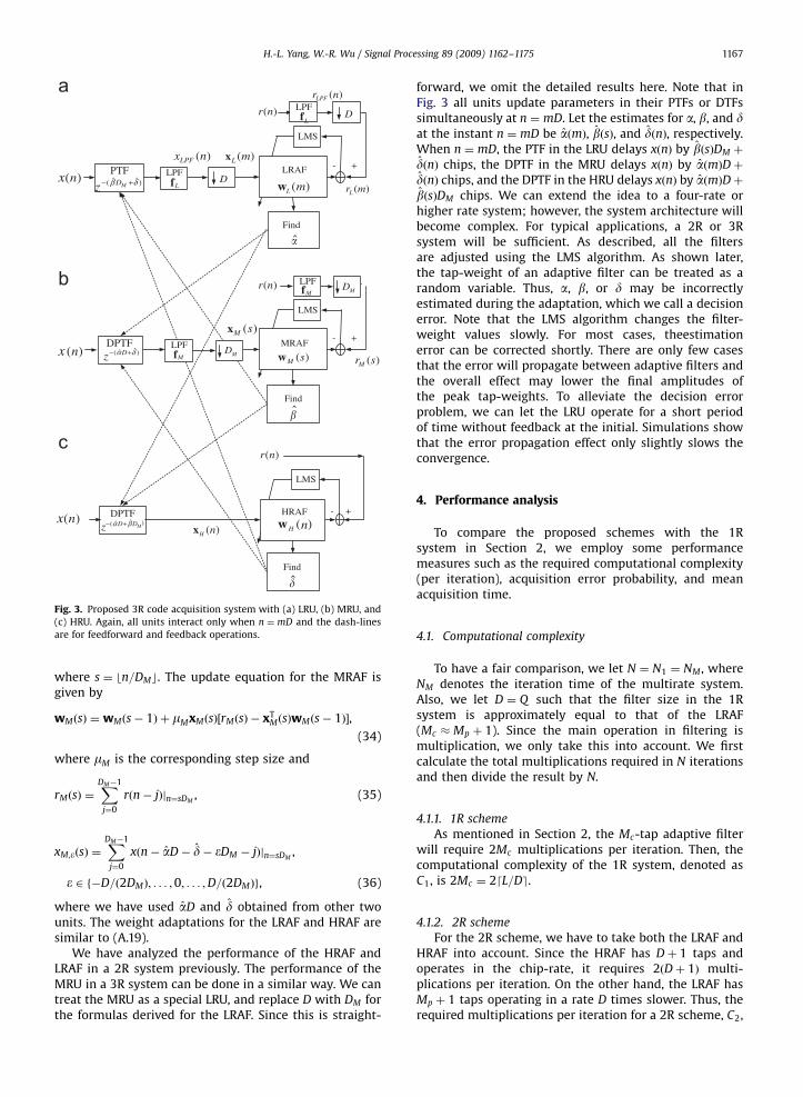
In the previous subsection, we have proposed a 2Rscheme that is able to null r. Since the HRAF operates in ahigh processing rate, it dominates the overall computa-tional complexity. This becomes an important issue whenthe tap-length Dþ 1 is large. We can solve the problem byintroducing a unit with another processing rate. We callthis unit as a medium-rate unit (MRU). This unit containsa medium-rate adaptive filter (MRAF) sharing the compu-tational loading of the HRAF. As shown in Fig. 3(b), theLPFs fM average rðnÞ and xðnÞ with a window side of DM ,and the decimators downsample the resultant signalswith a factor of DM . Let the DPTF denote the devicecascading the DTF and PTF. Here, the processing rate of theMRU is D=DM times faster than that of the LRU, but DM
times slower than that of the HRU.With the additional MRU, we have three resolutions to
work with. We can express the code delay ast ¼ aDþ bDM þ d, where a 2 f0;1; . . . ;Mpg;b 2 f�D=
ð2DMÞ; . . . ;0; . . . ;D=ð2DMÞg, and d 2 f�DM=2; . . . ;0; . . . ;DM=2g. For convenience, again, we assume that D=ð2DMÞ
and DM=2 are integers. Then, we use the LRU, MRU andHRU to estimate fa;b;dg, respectively. Note that�ðDþ DMÞ=2pbDM þ dpðDþ DMÞ=2, where DMX2. Inother words, the MRAF and HRAF can span a delay regiongreater than Dþ 1. Define the tap-weight vector and theinput vector of the MRAF as
wMðsÞ9½wM;�D=ð2DM ÞðsÞ; . . . ;wM;0ðsÞ; . . . ;wM;D=ð2DM Þ
ðsÞ�T, (32)
xMðsÞ9½xM;�D=ð2DM ÞðsÞ; . . . ; xM;0ðsÞ; . . . ; xM;D=ð2DM Þ
ðsÞ�T, (33)
ARTICLE IN PRESS
Fig. 3. Proposed 3R code acquisition system with (a) LRU, (b) MRU, and
(c) HRU. Again, all units interact only when n ¼ mD and the dash-lines
are for feedforward and feedback operations.
H.-L. Yang, W.-R. Wu / Signal Processing 89 (2009) 1162–1175 1167
where s ¼ bn=DMc. The update equation for the MRAF isgiven by
wMðsÞ ¼ wMðs� 1Þ þ mMxMðsÞ½rMðsÞ � xTMðsÞwMðs� 1Þ�,
(34)
where mM is the corresponding step size and
rMðsÞ ¼XDM�1
j¼0
rðn� jÞjn¼sDM, (35)
xM;�ðsÞ ¼XDM�1
j¼0
xðn� aD� d� �DM � jÞjn¼sDM,
� 2 f�D=ð2DMÞ; . . . ;0; . . . ;D=ð2DMÞg, (36)
where we have used aD and d obtained from other twounits. The weight adaptations for the LRAF and HRAF aresimilar to (A.19).
We have analyzed the performance of the HRAF andLRAF in a 2R system previously. The performance of theMRU in a 3R system can be done in a similar way. We cantreat the MRU as a special LRU, and replace D with DM forthe formulas derived for the LRAF. Since this is straight-
forward, we omit the detailed results here. Note that inFig. 3 all units update parameters in their PTFs or DTFssimultaneously at n ¼ mD. Let the estimates for a, b, and dat the instant n ¼ mD be aðmÞ, bðsÞ, and dðnÞ, respectively.When n ¼ mD, the PTF in the LRU delays xðnÞ by bðsÞDM þ
dðnÞ chips, the DPTF in the MRU delays xðnÞ by aðmÞDþdðnÞ chips, and the DPTF in the HRU delays xðnÞ by aðmÞDþbðsÞDM chips. We can extend the idea to a four-rate orhigher rate system; however, the system architecture willbecome complex. For typical applications, a 2R or 3Rsystem will be sufficient. As described, all the filtersare adjusted using the LMS algorithm. As shown later,the tap-weight of an adaptive filter can be treated as arandom variable. Thus, a, b, or d may be incorrectlyestimated during the adaptation, which we call a decisionerror. Note that the LMS algorithm changes the filter-weight values slowly. For most cases, theestimationerror can be corrected shortly. There are only few casesthat the error will propagate between adaptive filters andthe overall effect may lower the final amplitudes ofthe peak tap-weights. To alleviate the decision errorproblem, we can let the LRU operate for a short periodof time without feedback at the initial. Simulations showthat the error propagation effect only slightly slows theconvergence.
4. Performance analysis
To compare the proposed schemes with the 1Rsystem in Section 2, we employ some performancemeasures such as the required computational complexity(per iteration), acquisition error probability, and meanacquisition time.
4.1. Computational complexity
To have a fair comparison, we let N ¼ N1 ¼ NM , whereNM denotes the iteration time of the multirate system.Also, we let D ¼ Q such that the filter size in the 1Rsystem is approximately equal to that of the LRAF(Mc � Mp þ 1). Since the main operation in filtering ismultiplication, we only take this into account. We firstcalculate the total multiplications required in N iterationsand then divide the result by N.
4.1.1. 1R scheme
As mentioned in Section 2, the Mc-tap adaptive filterwill require 2Mc multiplications per iteration. Then, thecomputational complexity of the 1R system, denoted asC1, is 2Mc ¼ 2dL=De.
4.1.2. 2R scheme
For the 2R scheme, we have to take both the LRAF andHRAF into account. Since the HRAF has Dþ 1 taps andoperates in the chip-rate, it requires 2ðDþ 1Þ multi-plications per iteration. On the other hand, the LRAF hasMp þ 1 taps operating in a rate D times slower. Thus, therequired multiplications per iteration for a 2R scheme, C2,
ARTICLE IN PRESS
H.-L. Yang, W.-R. Wu / Signal Processing 89 (2009) 1162–11751168
is given by
C2 ¼
2ðMp þ 1ÞN
Dþ 2ðDþ 1ÞN
N(37)
¼2ðMp þ 1Þ
Dþ 2ðDþ 1Þ. (38)
4.1.3. 3R scheme
Similarly, we take the LRAF, MRAF, and HRAF intoaccount. The required multiplication per iteration for a 3Rsystem, C3, turns out to be
C3 ¼
2ðMp þ 1ÞN
Dþ 2
Dþ 1
DM
� �N
DMþ 2ðDM þ 1ÞN
N(39)
¼2ðMp þ 1Þ
Dþ
2
DM
Dþ 1
DM
� �þ 2ðDM þ 1Þ, (40)
where dðDþ 1Þ=DMe is the minimum required tap-lengthfor the MRAF.
4.2. Probability of acquisition error
For a general LMS adaptive filter with a step size mc , thetime to converge can be evaluated using d1=mce (see p. 348in [34]), which is called the time-constant. For theproposed 1R system, we have Q cells to adapt sequen-tially. To ensure that the steady state can be achievedclosely, we let the adaptation time be four time-constantsfor each cell. Therefore, the overall adaptation time for the1R system, denoted as N1, is then 4Qd1=mce. Let the stepsize for the adaptive filter in the 1R system and that in theHRAF be the same (i.e., mc ¼ mH9m). For multirate systemsdescribed in Section 3, we further let mL ¼ m=D andmM ¼ m=DM . In this way, the variances of these adaptivefilter taps are the same (see Eqs. (7) and (29)).
4.2.1. 2R scheme
An acquisition error may occur due to aaa, DaD, orboth. When the phase feedback to PTF is not correct, i.e.,DaD, the peak magnitude of wL;aðmÞ will be reduced, andthe overall acquisition performance will be affected. If weassume that there are no decision errors, the probability ofacquisition error for the time instant n, denoted as PeðnÞ,can be written as
PeðnÞ ¼ 1� PL;cðmÞPH;cðnÞ, (41)
PL;cðmÞ ¼ PðwL;cðmÞXwL;jðmÞÞ; caj; fc; jg 2 f0;1; . . . ;Mpg,
(42)
PH;cðnÞ ¼ PðwH;cðnÞXwH;jðnÞÞ,
caj; fc; jg 2 f�D=2; . . . ;0; . . . ;D=2g, (43)
where PL;cðmÞ and PH;cðnÞ denote the correct acquisitionprobabilities of the LRAF and HRAF, respectively. Also,wL;cðmÞ and wH;cðnÞ denote the taps whose tap-indicescorrespond to the actual code delay.
Using the transient analysis of LMS algorithms in [33],we have the mean weight vector of the LRAF as
EfwLðmÞg ¼ ½I� ðI� mLRLÞm�wL;o, (44)
and the ðMp þ 1Þ-by-ðMp þ 1Þ covariance matrix as
CLðmÞ ¼mLDs2
v
2½I� ðI� 2mLRLÞ
m�. (45)
Since RL ¼ DI, we can let CLðmÞ ¼ s2wLðmÞI where s2
wLðmÞ
is an equivalent variance that can be derived from (45).Here, wLðmÞ and wHðnÞ are assumed to be Gaussiandistributed. Similarly, we can have the mean weightvector and the covariance matrix of wHðnÞ as
EfwHðnÞg ¼ ½I� ðI� mHRHÞn�wH;o, (46)
and
CHðnÞ ¼mHs2
v
2½I� ðI� 2mHRHÞ
n�. (47)
Since RH ¼ I, we can let CHðnÞ ¼ s2wHðnÞI. Similarly,
s2wHðnÞ is an equivalent variance that can be derived from
(47). From Eqs. (45) and (47), we find that tap-weights areindependent and identically distributed. As mentioned,both the HRAF and LRAF are run for N chips. For notationalsimplicity, we let AL as the peak in EfwLðbN=DcÞg,s2
L ¼ s2wLðbN=DcÞ, PL ¼ PL;cðbN=DcÞ, AH as the peak in
EfwHðNÞg, s2H ¼ s2
wHðNÞ, PH ¼ PH;cðNÞ, and Pe ¼ PeðNÞ. The
probabilities in Eqs. (42) and (43) at n ¼ N turn out to be
PL ¼1ffiffiffiffiffiffiffiffiffiffiffiffi
2ps2L
q Z 1�1
1� Qw
sL
� �� �Mp
exp �ðw� ALÞ
2
2s2L
!dw,
(48)
PH ¼1ffiffiffiffiffiffiffiffiffiffiffiffi
2ps2H
q Z 1�1
1� Qw
sH
� �� �D
exp �ðw� AHÞ
2
2s2H
!dw.
(49)
Finally, we obtain
Pe ¼ 1� PLPH . (50)
As mentioned in Section 3, incorrect decisions can occurand the error propagation between the HRAF and LRAFwill lower the peak amplitudes of final tap-weights. Thus,the results in Eqs. (48)–(50) may be too optimistic.However, the exact analysis of the error propagationeffect turns out to be very difficult, if not impossible. Inwhat follows, we propose a simple approximation methodto overcome the problem. We first assume that the errorpropagation affects the mean of a tap-weight much moreserious than the variance. As a result, we only consider thevariation of mean weight vectors. For an adaptationperiod, a decision error can occur in any instant and theerror sequence can have many patterns. For simplicity, weonly investigate those affecting performance most. Con-sider the LRAF. It is simple to see that if there are kdecision errors during the adaptation period (i.e., betweenm ¼ 0 and bN=Dc), the error pattern corresponding to theworst performance will be the one when all errors occurbetween m ¼ bN=Dc � kþ 1 and bN=Dc. In other words,once a decision error occurs, the error will continue to theend of the adaptation period. This will make the peakweight value of the LRAF decrease from m ¼ bN=Dc � kþ1 monotonically. We then use this pattern to represent allpossible error patterns having k decision errors. From(44), we have AL ¼ 1� ð1� mLDÞbN=Dc. Taking the decision
ARTICLE IN PRESS
H.-L. Yang, W.-R. Wu / Signal Processing 89 (2009) 1162–1175 1169
errors into account, we may then rewrite AL as
ALðkÞ ¼ ½1� ð1� mLDÞbN=Dc�k� exp �
kZL
� �, (51)
where Z�1L ¼ mLlL and lL ¼ D is the eigenvalue of RL [34].
We may treat k as a random variable with a binomialdistribution as
pðkÞ ¼ bN=Dc
k
� �ð1� PLÞ
kPbN=Dc�kL , (52)
where PL is the correct probability in (48). We then useEqs. (51) and (52) to calculate the mean value of ALðkÞ,denoted as AL. It is given by
AL ¼XbN=Dc
k¼0
ALðkÞpðkÞ. (53)
Then, the probability of correct acquisition for the LRAF,denoted as PL, can be obtained by substituting AL into (48).Similarly, we can use the same procedure to obtain theprobability of correct acquisition for the HRAF, PH . Finally,the probability of acquisition error for a 2R system,denoted as PE, is obtained by
PE ¼ 1� PLPH . (54)
It is worth mentioning that PL and PH are thecorrect acquisition probabilities without decision errors.Thus, these values essentially correspond to two upperbounds of the correct acquisition probabilities. Usingthese values in the calculation of pðkÞ (as that in(52)) will underestimate the acquisition error probability.On the other hand, we only take the worst decisionerror patterns into consideration and this will over-estimate the acquisition error probability. Thus, (54) is aresult corresponding a compromise of these two extremecases.
N chips for
iteration ACQ
START
TpPEz
Tp+NPEz
1 − PE
ACQ
START
(1−PE) zN
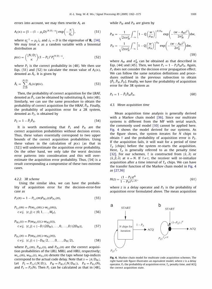
Fig. 4. Markov chain model for multirate code acquisition schemes. The
right hand side figure illustrates an equivalent model, where z is a delay
operator, PE the probability of acquisition error, Tp penalty time, and ACQ
the correct acquisition state.
4.2.2. 3R scheme
Using the similar idea, we can have the probabi-lity of acquisition error for the decision-error-freecase as
PeðnÞ ¼ 1� PL;cðmÞPM;cðsÞPH;cðnÞ, (55)
PL;cðmÞ ¼ PðwL;cðmÞXwL;jðmÞÞ,
caj; fc; jg 2 f0;1; . . . ;Mpg, (56)
PM;cðsÞ ¼ PðwM;cðsÞXwM;jðsÞÞ,
caj; fc; jg 2 f�D=ð2DMÞ; . . . ;0; . . . ;D=ð2DMÞg, (57)
PH;cðnÞ ¼ PðwH;cðnÞXwH;jðnÞÞ,
caj; fc; jg 2 f�DM=2; . . . ;0; . . . ;DM=2g, (58)
where PL;cðmÞ, PM;cðsÞ, and PH;cðnÞ are the correct acquisi-tion probabilities of the LRU, MRU, and HRU, respectively;wL;cðmÞ, wM;cðsÞ, wH;cðnÞ denote the taps whose tap-indicescorrespond to the actual code delay. Note that s ¼ bn=DMc.Let PL ¼ PL;cðbN=DcÞ, PM ¼ PM;cðbN=DMcÞ, PH ¼ PH;cðNÞ,and Pe ¼ PeðNÞ. Then PL can be calculated as that in (48),
while PM and PH are given by
PM ¼1ffiffiffiffiffiffiffiffiffiffiffiffiffi
2ps2M
q Z 1�1
1� Qw
sM
� �� �D=DM
exp �ðw� AMÞ
2
2s2M
!dw,
PH ¼1ffiffiffiffiffiffiffiffiffiffiffiffi
2ps2H
q Z 1�1
1� Qw
sH
� �� �DM
exp �ðw� AHÞ
2
2s2H
!dw,
(59)
where AM and s2M can be obtained as that described in
Eqs. (44) and (45). Then, we have Pe ¼ 1� PLPMPH . Again,Pe does not consider the decision error propagation effect.We can follow the same notation definitions and proce-dures outlined in the previous subsection to obtain{PL; PM ; PH}. Finally, we have the probability of acquisitionerror for the 3R system as
PE ¼ 1� PLPMPH . (60)
4.3. Mean acquisition time
Mean acquisition time analysis is generally derivedwith a Markov chain model [36]. Since our multiratesystems is different from the MF with serial search,the commonly used model [10] cannot be applied here.Fig. 4 shows the model derived for our systems. Asthe figure shows, the system iterates for N chips toobtain t and the probability of acquisition error is PE.If the acquisition fails, it will wait for a period of timeTp (chips) before the system re-starts the acquisition.Here, Tp is generally referred to as the penalty time[32]. For our schemes, t is constructed from fa; Dg orfa; b; dg at n ¼ N. If tat, the receiver will re-initializeacquisition after a time interval of Tp chips. We can havethe transfer function of the Markov chain model in Fig. 4as [27,36]
HðzÞ ¼ð1� PEÞz
N
1� PEzTpþN, (61)
where z is a delay operator and PE is the probability ofacquisition error formulated above. The mean acquisition
ARTICLE IN PRESS
H.-L. Yang, W.-R. Wu / Signal Processing 89 (2009) 1162–11751170
time can then be easily found as
Tacq9d
dzHðzÞjz¼1 (62)
¼ N þðTp þ NÞPE
ð1� PEÞ. (63)
Note that the unit of Tacq is chip.
5. Simulation results
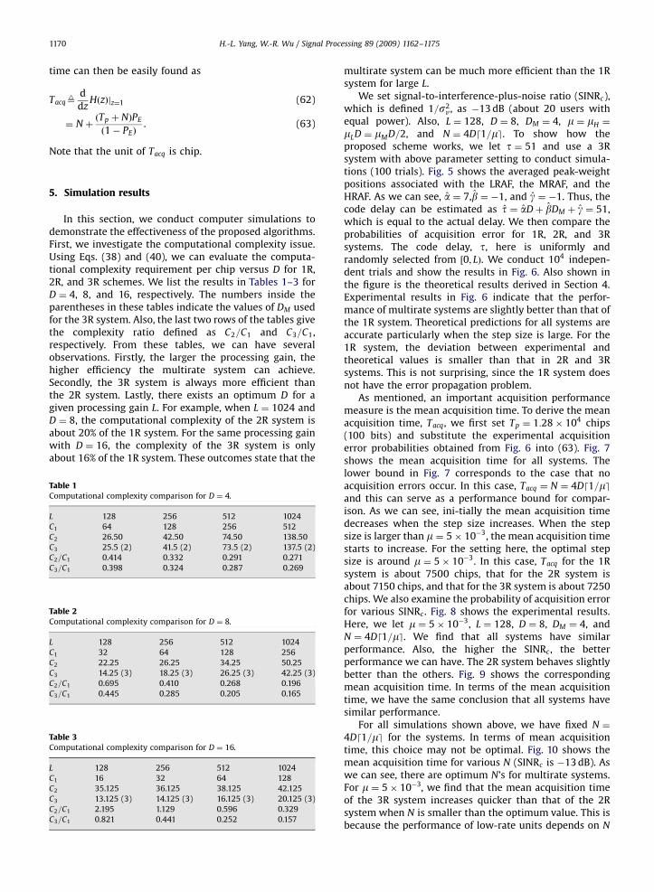
In this section, we conduct computer simulations todemonstrate the effectiveness of the proposed algorithms.First, we investigate the computational complexity issue.Using Eqs. (38) and (40), we can evaluate the computa-tional complexity requirement per chip versus D for 1R,2R, and 3R schemes. We list the results in Tables 1–3 forD ¼ 4, 8, and 16, respectively. The numbers inside theparentheses in these tables indicate the values of DM usedfor the 3R system. Also, the last two rows of the tables givethe complexity ratio defined as C2=C1 and C3=C1,respectively. From these tables, we can have severalobservations. Firstly, the larger the processing gain, thehigher efficiency the multirate system can achieve.Secondly, the 3R system is always more efficient thanthe 2R system. Lastly, there exists an optimum D for agiven processing gain L. For example, when L ¼ 1024 andD ¼ 8, the computational complexity of the 2R system isabout 20% of the 1R system. For the same processing gainwith D ¼ 16, the complexity of the 3R system is onlyabout 16% of the 1R system. These outcomes state that the
Table 1Computational complexity comparison for D ¼ 4.
L 128 256 512 1024
C1 64 128 256 512
C2 26.50 42.50 74.50 138.50
C3 25.5 (2) 41.5 (2) 73.5 (2) 137.5 (2)
C2=C1 0.414 0.332 0.291 0.271
C3=C1 0.398 0.324 0.287 0.269
Table 2Computational complexity comparison for D ¼ 8.
L 128 256 512 1024
C1 32 64 128 256
C2 22.25 26.25 34.25 50.25
C3 14.25 (3) 18.25 (3) 26.25 (3) 42.25 (3)
C2=C1 0.695 0.410 0.268 0.196
C3=C1 0.445 0.285 0.205 0.165
Table 3Computational complexity comparison for D ¼ 16.
L 128 256 512 1024
C1 16 32 64 128
C2 35.125 36.125 38.125 42.125
C3 13.125 (3) 14.125 (3) 16.125 (3) 20.125 (3)
C2=C1 2.195 1.129 0.596 0.329
C3=C1 0.821 0.441 0.252 0.157
multirate system can be much more efficient than the 1Rsystem for large L.
We set signal-to-interference-plus-noise ratio (SINRc),which is defined 1=s2
v, as �13 dB (about 20 users withequal power). Also, L ¼ 128, D ¼ 8, DM ¼ 4, m ¼ mH ¼
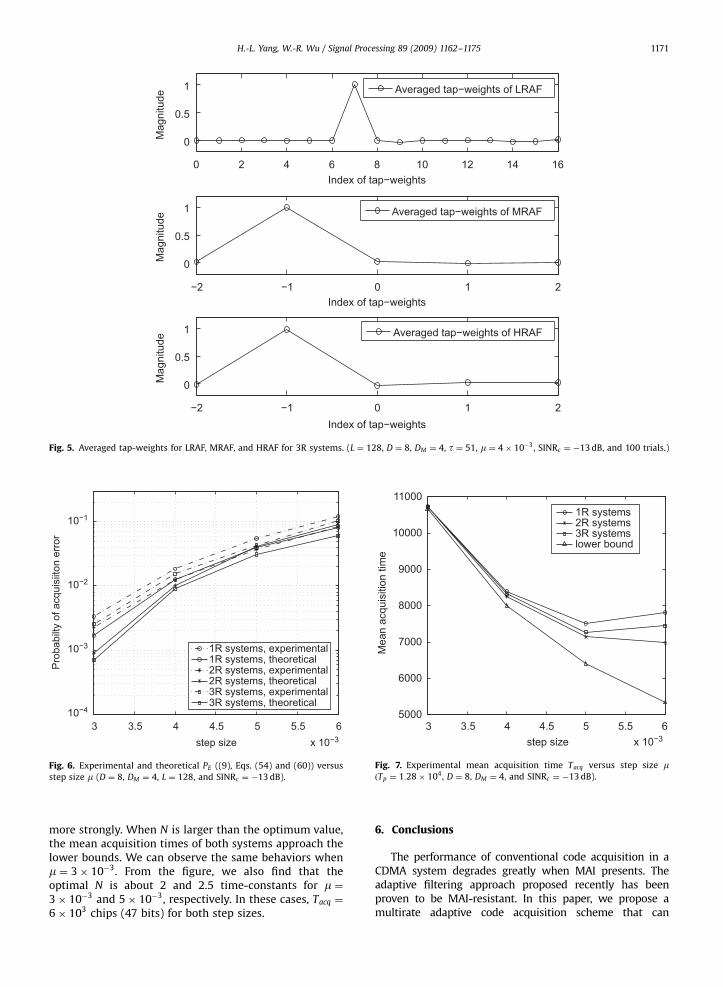
mLD ¼ mMD=2, and N ¼ 4Dd1=me. To show how theproposed scheme works, we let t ¼ 51 and use a 3Rsystem with above parameter setting to conduct simula-tions (100 trials). Fig. 5 shows the averaged peak-weightpositions associated with the LRAF, the MRAF, and theHRAF. As we can see, a ¼ 7,b ¼ �1, and g ¼ �1. Thus, thecode delay can be estimated as t ¼ aDþ bDM þ g ¼ 51,which is equal to the actual delay. We then compare theprobabilities of acquisition error for 1R, 2R, and 3Rsystems. The code delay, t, here is uniformly andrandomly selected from ½0; LÞ. We conduct 104 indepen-dent trials and show the results in Fig. 6. Also shown inthe figure is the theoretical results derived in Section 4.Experimental results in Fig. 6 indicate that the perfor-mance of multirate systems are slightly better than that ofthe 1R system. Theoretical predictions for all systems areaccurate particularly when the step size is large. For the1R system, the deviation between experimental andtheoretical values is smaller than that in 2R and 3Rsystems. This is not surprising, since the 1R system doesnot have the error propagation problem.
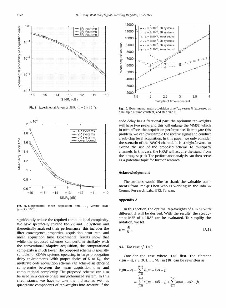
As mentioned, an important acquisition performancemeasure is the mean acquisition time. To derive the meanacquisition time, Tacq, we first set Tp ¼ 1:28� 104 chips(100 bits) and substitute the experimental acquisitionerror probabilities obtained from Fig. 6 into (63). Fig. 7shows the mean acquisition time for all systems. Thelower bound in Fig. 7 corresponds to the case that noacquisition errors occur. In this case, Tacq ¼ N ¼ 4Dd1=meand this can serve as a performance bound for compar-ison. As we can see, ini-tially the mean acquisition timedecreases when the step size increases. When the stepsize is larger than m ¼ 5� 10�3, the mean acquisition timestarts to increase. For the setting here, the optimal stepsize is around m ¼ 5� 10�3. In this case, Tacq for the 1Rsystem is about 7500 chips, that for the 2R system isabout 7150 chips, and that for the 3R system is about 7250chips. We also examine the probability of acquisition errorfor various SINRc . Fig. 8 shows the experimental results.Here, we let m ¼ 5� 10�3, L ¼ 128, D ¼ 8, DM ¼ 4, andN ¼ 4Dd1=me. We find that all systems have similarperformance. Also, the higher the SINRc , the betterperformance we can have. The 2R system behaves slightlybetter than the others. Fig. 9 shows the correspondingmean acquisition time. In terms of the mean acquisitiontime, we have the same conclusion that all systems havesimilar performance.
For all simulations shown above, we have fixed N ¼
4Dd1=me for the systems. In terms of mean acquisitiontime, this choice may not be optimal. Fig. 10 shows themean acquisition time for various N (SINRc is �13 dB). Aswe can see, there are optimum N’s for multirate systems.For m ¼ 5� 10�3, we find that the mean acquisition timeof the 3R system increases quicker than that of the 2Rsystem when N is smaller than the optimum value. This isbecause the performance of low-rate units depends on N
ARTICLE IN PRESS
3 3.5 4 4.5 5 5.5 6x 10⁻³
10−4
10−3
10−2
10−1
step size
Pro
babi
lty o
f acq
uisi
iton
erro
r
1R systems, experimental1R systems, theoretical2R systems, experimental2R systems, theoretical3R systems, experimental3R systems, theoretical
Fig. 6. Experimental and theoretical PE ((9), Eqs. (54) and (60)) versus
step size m (D ¼ 8, DM ¼ 4, L ¼ 128, and SINRc ¼ �13 dB).
0 2 4 6 8 10 12 14 16
0
0.5
1
Index of tap−weights
Mag
nitu
de
Averaged tap−weights of LRAF
−2 −1 0 1 2
0
0.5
1
Index of tap−weights
Mag
nitu
de
Averaged tap−weights of MRAF
−2 −1 0 1 2
0
0.5
1
Index of tap−weights
Mag
nitu
de
Averaged tap−weights of HRAF
Fig. 5. Averaged tap-weights for LRAF, MRAF, and HRAF for 3R systems. (L ¼ 128, D ¼ 8, DM ¼ 4, t ¼ 51, m ¼ 4� 10�3, SINRc ¼ �13 dB, and 100 trials.)
3 3.5 4 4.5 5 5.5 6x 10⁻³
5000
6000
7000
8000
9000
10000
11000
step size
Mea
n ac
quis
ition
tim
e
1R systems2R systems3R systemslower bound
Fig. 7. Experimental mean acquisition time Tacq versus step size mðTp ¼ 1:28� 104, D ¼ 8, DM ¼ 4, and SINRc ¼ �13 dB).
H.-L. Yang, W.-R. Wu / Signal Processing 89 (2009) 1162–1175 1171
more strongly. When N is larger than the optimum value,the mean acquisition times of both systems approach thelower bounds. We can observe the same behaviors whenm ¼ 3� 10�3. From the figure, we also find that theoptimal N is about 2 and 2.5 time-constants for m ¼3� 10�3 and 5� 10�3, respectively. In these cases, Tacq ¼
6� 103 chips (47 bits) for both step sizes.
6. Conclusions
The performance of conventional code acquisition in aCDMA system degrades greatly when MAI presents. Theadaptive filtering approach proposed recently has beenproven to be MAI-resistant. In this paper, we propose amultirate adaptive code acquisition scheme that can
ARTICLE IN PRESS
−16 −15 −14 −13 −12 −11 −1010−4
10−3
10−2
10−1
100
Exp
erim
enta
l pro
babi
lity
of a
cqui
sitio
n er
ror
1R systems2R systems3R systems
SINRc (dB)
Fig. 8. Experimental PE versus SINRc ðm ¼ 5� 10�3Þ.
−16 −15 −14 −13 −12 −11 −100.6
0.8
1
1.2
1.4
1.6
1.8
2x 10⁴
Mea
n ac
quis
ition
tim
e
1R systems2R systems3R systemslower bound
SINRc (dB)
Fig. 9. Experimental mean acquisition time Tacq versus SINRc
ðm ¼ 5� 10�3Þ.
1.5 2 2.5 3 3.5 42000
3000
4000
5000
6000
7000
8000
9000
10000
11000
12000
multiple of time−constant
Mea
n ac
quis
ition
tim
e
μ = 3×10⁻³, 2R systemsμ = 3×10⁻³, 3R systemsμ = 3×10⁻³, lower boundμ = 5×10⁻³, 2R systemsμ = 5×10⁻³, 3R systemsμ = 5×10⁻³, lower bound
Fig. 10. Experimental mean acquisition time Tacq versus N (expressed as
a multiple of time-constant) and step size m.
H.-L. Yang, W.-R. Wu / Signal Processing 89 (2009) 1162–11751172
significantly reduce the required computational complexity.We have specifically studied the 2R and 3R systems andtheoretically analyzed their performance; this includes thefilter convergence properties, acquisition error rate, andmean acquisition time. Experimental results show thatwhile the proposed schemes can perform similarly withthe conventional adaptive acquisition, the computationalcomplexity is much lower. The proposed scheme is speciallysuitable for CDMA systems operating in large propagationdelay environments. With proper choice of D or DM, themultirate code acquisition scheme can achieve an efficientcompromise between the mean acquisition time andcomputational complexity. The proposed scheme can alsobe used in a carrier-phase unsynchronized system. In thiscircumstance, we have to take the inphase as well asquadrature components of tap-weights into account. If the
code delay has a fractional part, the optimum tap-weightswill have two peaks and this will enlarge the MMSE, whichin turn affects the acquisition performance. To mitigate thisproblem, we can oversample the receive signal and conducta sub-chip level acquisition. In this paper, we only considerthe scenario of the AWGN channel. It is straightforward toextend the use of the proposed scheme to multipathchannels. In this case, the HRAF will acquire the signal fromthe strongest path. The performance analysis can then serveas a potential topic for further research.
Acknowledgement
The authors would like to thank the valuable com-ments from Ren-Jr Chen who is working in the Info. &Comm. Research Lab., ITRI, Taiwan.
Appendix A
In this section, the optimal tap-weights of a LRAF withdifferent D will be derived. With the results, the steady-state MSE of a LRAF can be evaluated. To simplify thenotation, we let
r ¼ jDjD
. (A.1)
A.1. The case of DX0
Consider the case where DX0 first. The elementxLðm� �Þ, � 2 f0;1; . . . ;Mpg in (18) can be rewritten as
xLðm� �Þ ¼XD�1
j¼0
xððm� �ÞD� jÞ
¼XD�1
j¼0
xððm� �ÞD� jÞ þXD�1
j¼D
xððm� �ÞD� jÞ
ARTICLE IN PRESS
H.-L. Yang, W.-R. Wu / Signal Processing 89 (2009) 1162–1175 1173
¼XD�1
j¼0
xððm� �ÞD� jÞ þXD�D�1
j¼0
xððm� �ÞD�D� jÞ
¼ffiffiffiffiffiffiffiDr
p 1ffiffiffiffiffiffiffiDr
p XD�1
j¼0
xððm� �ÞD� jÞ
8<:
9=;
þffiffiffiffiffiffiffiffiffiffiffiffiffiffiffiffiffiffiffiDð1� rÞ
p 1ffiffiffiffiffiffiffiffiffiffiffiffiffiffiffiffiffiffiffiDð1� rÞ
p(
XD�D�1
j¼0
xððm� �ÞD�D� jÞ
9=;. (A.2)
Let
yðmÞ ¼1ffiffiffiffiffiffiffiDr
p XD�1
j¼0
xðmD� jÞ, (A.3)
fðmÞ ¼1ffiffiffiffiffiffiffiffiffiffiffiffiffiffiffiffiffiffiffi
Dð1� rÞp XD�D�1
j¼0
xðmD�D� jÞ, (A.4)
HðmÞ ¼ ½yðmÞ; yðm� 1Þ; . . . ; yðm�MpÞ�T, and UðmÞ ¼
½fðmÞ; fðm� 1Þ; . . . ;fðm�MpÞ�T. Thus, (A.2) can be writ-
ten as
xLðm� �Þ ¼ffiffiffiffiffiffiffiDr
pyðm� �Þ þ
ffiffiffiffiffiffiffiffiffiffiffiffiffiffiffiffiffiffiffiDð1� rÞ
pfðm� �Þ,
� 2 f0;1; . . . ;Mpg, (A.5)
and (18) as
xLðmÞ ¼ffiffiffiffiffiffiffiDr
pHðmÞ þ
ffiffiffiffiffiffiffiffiffiffiffiffiffiffiffiffiffiffiffiDð1� rÞ
pUðmÞ. (A.6)
Note that yðmÞ, fðmÞ and vLðmÞ are zero mean, mutuallyuncorrelated, and
EfyðmÞyðm� �Þg ¼ dð�Þ,EffðmÞfðm� �Þg ¼ dð�Þ,
EfvLðmÞvLðm� �Þg ¼ Ds2vdð�Þ, (A.7)
where dð�Þ denotes a Kronecker Dirac delta function. UsingEqs. (A.3) and (A.4), we can also express (15) as
rLðmÞ ¼XD�1
j¼0
xððm� aÞD�D� jÞ þ vLðmÞ
¼XD�D�1
j¼0
xððm� aÞD�D� jÞ
þXD�1
j¼D�D
xððm� aÞD� D� jÞ þ vLðmÞ
¼XD�D�1
j¼0
xððm� aÞD�D� jÞ
þXD�1
j¼0
xððm� a� 1ÞD� jÞ þ vLðmÞ
¼ffiffiffiffiffiffiffiffiffiffiffiffiffiffiffiffiffiffiffiDð1� rÞ
pfðm� aÞ þ
ffiffiffiffiffiffiffiDr
pyðm� a� 1Þ þ vLðmÞ.
(A.8)
rLðmÞ
¼ xTL ðmÞwL;o þ vLðmÞ
�ð1� rÞffiffiffiffiffiffiffiDr
p½yðm� aÞ � yðm� a� 1Þ� þ r
ffiffiffiffiffiffiffiffiffiffiffiffiffiffiffiffiffiffiffiDð1� rÞ
p|fflfflfflfflfflfflfflfflfflfflfflfflfflfflfflfflfflfflfflfflfflfflfflfflfflfflfflfflfflfflfflfflfflfflfflfflfflfflfflfflfflfflfflfflfflfflfflfflfflfflfflfflfflfflfflfflfflfflfflfflfflfflfflfflfflfflfflfflfflfflfflfflfflfflfflfflfflfflfflfflfflfflffl{zfflfflfflfflfflfflfflfflfflfflfflfflfflfflfflfflfflfflfflfflfflfflfflfflfflfflfflffl9xðmÞ
Let the tap-weights of the LRAF bewLðmÞ ¼ ½wL;0ðmÞ;wL;1ðmÞ; . . . ;wL;Mp
ðmÞ�T. Also, let the cor-responding optimal solution be wL;o. Using the corre-sponding Wiener equations, we can have
wL;o ¼ R�1L pL, (A.9)
where pL9EfxLðmÞrLðmÞg and RL9EfxLðmÞxTL ðmÞg. From
Eqs. (A.6) and (A.7), it is simple to derive
RL ¼ DI. (A.10)
Using Eqs. (A.6) and (A.8), we can find the cross-correlation between rLðmÞ and xLðmÞ as
pL ¼ 0; . . . ;0|fflfflfflffl{zfflfflfflffl}a
;D�D;D;0; . . . ;0
24
35T
(A.11)
From (A.9), we obtain
wL;o;� ¼
1� r; � ¼ a;r; � ¼ aþ 1;
0 otherwise;
8><>: � 2 f0;1; . . . ;Mpg, (A.12)
where wL;o;� is the �th element of wL;o. Let the MSE that theWiener filter minimizes be JLðmÞ. Then,
JLðmÞ ¼ Ef½rLðmÞ �wTL ðmÞxLðmÞ�
2g
¼ Efr2L ðmÞg � 2wT
L ðmÞpL þwTL ðmÞRLwLðmÞ, (A.13)
where Efr2L ðmÞg ¼ DEfr2ðnÞg ¼ Dðs2
v þ 1Þ. Replacing wLðmÞ
with wL;o, we can obtain the corresponding MMSE, JL;min,as
JL;min ¼ DEfr2ðnÞg � D½ð1� rÞ2 þ r2�
¼ D½s2v þ 2rð1� rÞ�. (A.14)
From (A.14), we can see that a nonzero r will producean extra term in the MMSE. We now proceed to find theMSE yielded by the LMS algorithm. Using Eqs. (A.6) and(A.12), we derive
xTL ðmÞwL;o ¼ ð1� rÞf
ffiffiffiffiffiffiffiDr
pyðm� aÞ þ
ffiffiffiffiffiffiffiffiffiffiffiffiffiffiffiffiffiffiffiDð1� rÞ
pfðm� aÞg
þ rfffiffiffiffiffiffiffiDr
pyðm� a� 1Þ
þffiffiffiffiffiffiffiffiffiffiffiffiffiffiffiffiffiffiffiDð1� rÞ
pfðm� a� 1Þg (A.15)
¼ffiffiffiffiffiffiffiDr
pyðm� aÞ þ
ffiffiffiffiffiffiffiffiffiffiffiffiffiffiffiffiffiffiffiDð1� rÞ
pfðm� aÞ
� rffiffiffiffiffiffiffiDr
pyðm� aÞ � r
ffiffiffiffiffiffiffiffiffiffiffiffiffiffiffiffiffiffiffiDð1� rÞ
pfðm� aÞ
þ rffiffiffiffiffiffiffiDr
pyðm� a� 1Þ
þ rffiffiffiffiffiffiffiffiffiffiffiffiffiffiffiffiffiffiffiDð1� rÞ
pfðm� a� 1Þ. (A.16)
Substituting (A.8) into (A.16), we obtain
xTL ðmÞwL;o ¼ rLðmÞ � vLðmÞ þ ð1� rÞ
ffiffiffiffiffiffiffiDr
p�fyðm� aÞ � yðm� a� 1Þg
� rffiffiffiffiffiffiffiffiffiffiffiffiffiffiffiffiffiffiffiDð1� rÞ
pffðm� aÞ �fðm� a� 1Þg.
(A.17)
Rewriting (A.17), we have
½fðm� aÞ � fðm� a� 1Þ�fflfflfflfflfflfflfflfflfflfflfflfflfflfflfflfflfflfflfflfflfflfflfflfflfflfflfflfflfflfflfflfflfflfflfflfflfflfflfflfflfflfflfflfflfflfflfflfflfflfflfflfflfflfflffl} , (A.18)
ARTICLE IN PRESS
H.-L. Yang, W.-R. Wu / Signal Processing 89 (2009) 1162–11751174
where xðmÞ is zero mean and its variance iss2x ¼ 2Drð1� rÞ. The LMS tap-weight update equation
for the LRAF is given by
wLðmÞ ¼ wLðm� 1Þ þ mLxLðmÞ½rLðmÞ � xTL ðmÞwLðm� 1Þ�,
(A.19)
where mL is the step size. Substituting (A.18) into (A.19),we have
wLðmÞ ¼ wLðm� 1Þ þ mLxLðmÞ½xTL ðmÞwL;o þ vLðmÞ þ xðmÞ
� xTL ðmÞwLðm� 1Þ�. (A.20)
Subtracting wL;o on both sides of (A.20) and lettingDwLðmÞ ¼ wLðmÞ �wL;o, we can rewrite (A.20) as
DwLðmÞ ¼ DwLðm� 1Þ � mLxLðmÞxTL ðmÞDwLðm� 1Þ
þ mLxLðmÞvLðmÞ þ mLxLðmÞxðmÞ
¼ ½I� mLxLðmÞxTL ðmÞ�DwLðm� 1Þ
þ mLxLðmÞvLðmÞ þ mLxLðmÞxðmÞ. (A.21)
Let Q ðmÞ ¼ EfDwLðmÞDwTL ðmÞg. Then,
Q ðmÞ ¼ Ef½I� mLxLðmÞxTL ðmÞ�DwLðm� 1Þ
� DwTL ðm� 1Þ½I� mLxLðmÞx
TL ðmÞ�
Tg
þ m2L Efv2
L ðmÞxLðmÞxTL ðmÞg
þ m2L Efx2
ðmÞxLðmÞxTL ðmÞg. (A.22)
Eq. (A.22) can be written as
Q ðmÞ ¼ ðI� mLRLÞQ ðm� 1ÞðI� mLRLÞ
þ m2L Ds2
vRL þ m2Ls
2xRL. (A.23)
Note that in (A.23) we implicitly assume that x2ðmÞ and
xLðmÞxTL ðmÞ are uncorrelated. The �th entry on the main
diagonal of Q ðmÞ is
Q �;�ðmÞ ¼ ð1� mLDÞ2Q �;�ðm� 1Þ þ m2L D2s2
v þ m2L Ds2
x .
(A.24)
When m�!1, we have the asymptotic result as
Q �;�ðmÞ �mL
2ðDs2
v þ s2xÞ
¼mLD
2½s2
v þ 2rð1� rÞ� � 2 f0;1; . . . ;Mpg. (A.25)
Using Eqs. (A.14) and (A.25), we can have the MSE forthe LMS algorithm in steady-state [34] as
JLð1Þ ¼ JL;min þðMp þ 1ÞmLD
2½s2
v þ 2rð1� rÞ�
¼ 1þðMp þ 1ÞmL
2
� �JL;min. (A.26)
A.2. The case of Do0
Next, let us consider the case where Do0. We define anew set of yðmÞ and fðmÞ as
yðmÞ91ffiffiffiffiffiffiffiffiffiffiffiffiffiffiffiffiffiffiffi
Dð1� rÞp XD�jDj�1
j¼0
xðmD� jÞ, (A.27)
fðmÞ91ffiffiffiffiffiffiffiDr
p XjDj�1
j¼0
xððm� 1ÞDþ jDj � jÞ. (A.28)
Then, we can have xLðm� �Þ as
xLðm� �Þ ¼XD�1
j¼0
xððm� �ÞD� jÞ (A.29)
¼XD�jDj�1
j¼0
xððm� �ÞD� jÞ
þXD�1
j¼D�jDj
xððm� �ÞD� jÞ (A.30)
¼XD�jDj�1
j¼0
xððm� �ÞD� jÞ
þXjDj�1
j¼0
xððm� �� 1ÞDþ jDj � jÞ (A.31)
¼ffiffiffiffiffiffiffiffiffiffiffiffiffiffiffiffiffiffiffiDð1� rÞ
pyðm� �Þ þ
ffiffiffiffiffiffiffiDr
pfðm� �Þ, (A.32)
and (15) as
rLðmÞ ¼XD�1
j¼0
xððm� aÞDþ jDj � jÞ þ vLðmÞ (A.33)
¼XjDj�1
j¼0
xððm� aÞDþ jDj � jÞ þXD�1
j¼jDj
xððm� aÞD
þ jDj � jÞ þ vLðmÞ (A.34)
¼XjDj�1
j¼0
xððm� aÞDþ jDj � jÞ
þXD�jDj�1
j¼0
xððm� aÞD� jÞ þ vLðmÞ (A.35)
¼ffiffiffiffiffiffiffiDr
pfðm� aþ 1Þ þ
ffiffiffiffiffiffiffiffiffiffiffiffiffiffiffiffiffiffiffiDð1� rÞ
pyðm� aÞ þ vLðmÞ.
(A.36)
Following the similar procedure for the case that DX0,we can derive
wL;o;� ¼
1� r; � ¼ a;r; � ¼ a� 1;
0 otherwise;
8><>: � 2 f0;1; . . . ;Mpg, (A.37)
and
JLð1Þ ¼ JL;min þðMp þ 1ÞmLD
2½s2
v þ 2rð1� rÞ�
¼ 1þðMp þ 1ÞmL
2
� �JL;min. (A.38)
References
[1] A. Polydoros, C.L. Weber, A unified approach to serial search spread-spectrum code acquisition—part II: a matched-filter receiver, IEEETransactions on Communications 32 (5) (May 1984) 550–560.
[2] R.R. Rick, L.B. Milstein, Parallel acquisition in mobile DS-CDMAsystems, IEEE Transactions on Communications 45 (11) (November1997) 1466–1476.
[3] Yu T. Su, Rapid code acquisition algorithms employing PN matchedfilters, IEEE Transactions on Communications 36 (6) (June 1988)724–733.
[4] E. Sourour, S.C. Gupta, Direct-sequence spread-spectrum parallelacquisition in a fading mobile channel, IEEE Transactions onCommunications 38 (7) (1990) 992–998.
[5] T.K. Moon, R.T. Short, C.K. Rushforth, Average acquisition time forSSMA channels, in: IEEE Military Communication Conference, 1991,pp. 1042–1046.
ARTICLE IN PRESS
H.-L. Yang, W.-R. Wu / Signal Processing 89 (2009) 1162–1175 1175
[6] G.E. Corazza, V. Degli-Esposti, Acquisition-based capacity estimatesfor CDMA with imperfect power control, in: IEEE InternationalSymposium on Spread Spectrum Techniques and Applications, vol.1, July 1994, pp. 325–329.
[7] U. Madhow, M.B. Pursley, Acquisition in direct-sequence spread-spectrum communication networks: an asymptotic analysis, IEEETransactions on Information Theory 39 (3) (May 1993) 903–912.
[8] R.L. Pickholtz, L.B. Milstein, D.L. Schilling, Spread spectrum formobile communication, IEEE Transactions on Vehicular Technology40 (2) (May 1991) 313–322.
[9] A.G. Dabak, Acquisition based capacity of a synchronous directsequence spread spectrum multiple access technique, in: IEEEInternational Symposium on Information Theory, 1994, p. 141.
[10] J.K. Holmes, C.C. Chen, Acquisition time performance of PN spread-spectrum systems, IEEE Transactions on Communications 25 (8)(May 1977) 778–783.
[11] H.-C. Hwang, C.-H. Wei, A new blind adaptive interferencesuppression scheme for acquisition and MMSE demodulation ofDS/CDMA signals, IEEE Transactions on Vehicular Technology 49 (3)(May 2000) 875–884.
[12] E.G. Strom, S. Parkvall, S.L. Miller, B.E. Ottersten, Propagation delayestimation in asynchronous direct-sequence code-division multipleaccess systems, IEEE Transactions on Communications 44 (1)(January 1996) 84–93.
[13] S.E. Bensley, B. Aazhang, Subspace-based channel estimation forcode division multiple access communication systems, IEEETransactions on Communications 44 (8) (August 1996) 1009–1020.
[14] S. Kim, Improved MUSIC algorithm for the code-timing estimationof DS-CDMA multipath-fading channels in multiantenna systems,IEEE Transactions on Vehicular Technology 53 (5) (September 2004)1354–1369.
[15] P.K.P. Cheung, P.B. Rapajic, CMA-based code acquisition scheme forDS-CDMA systems, IEEE Transactions on Communications 48 (5)(May 2000) 852–862.
[16] R. Wang, H. Li, T. Li, Code-timing estimation for CDMA systems withbandlimited chip waveforms, IEEE Transactions on Wireless Com-munications 3 (4) (July 2004) 1338–1348.
[17] Y. Ma, K.H. Li, A.C. Kot, G. Ye, A blind code timing estimator and itsimplementation for DS-CDMA signals in unknown colored noise,IEEE Transactions on Vehicular Technology 51 (6) (November 2002)1600–1607.
[18] D. Zheng, J. Li, S.L. Miller, E.G. Strom, An efficient code-timingestimator for DS-CDMA signals, IEEE Transactions on SignalProcessing 45 (January 1997) 82–89.
[19] M.G. El-Tarhuni, A.U.H. Sheikh, PN code acquisition in CDMAsystems using a MMSE adaptive filter, in: IEEE Canadian Conferenceon Electrical and Computer Engineering, vol. 2, May 1998, pp.746–749.
[20] M.G. El-Tarhuni, A.U.H. Sheikh, An adaptive filtering PN codeacquisition scheme with improved acquisition based capacity in
DS/CDMA, in: Ninth IEEE International Symposium on Personal,Indoor and Mobile Radio Communications, vol. 3, September 1998,pp. 1486–1490.
[21] M.G. El-Tarhuni, A.U.H. Sheikh, Adaptive synchronization for spreadspectrum systems, in: 46th IEEE Vehicular Technology Conference,vol. 1, 1996, pp. 170–174.
[22] M.G. El-Tarhuni, Application of adaptive filtering to direct-sequencespread-spectrum code synchronization, Ph.D. Thesis proposal,Department of System and Computer Engineering, Carletonuniversity, Canada, January 1996.
[23] T. Yu, J. Kwun, H. Jeon, D. Hong, C. Kang, Noncoherent adaptivecode synchronization for DS/CDMA systems, in: IEEE GlobalTelecommunications Conference, vol. 6, November 2001,pp. 3311–3315.
[24] M.G. El-Tarhuni, A.U.H. Sheikh, Code acquisition of DS/SS signals infading channels using an LMS adaptive filter, IEEE CommunicationLetters 2 (4) (April 1998) 85–88.
[25] H.L. Yang, W.R. Wu, Multirate adaptive filtering for DS/CDMAcode acquisition, in: IEEE International Symposium on SignalProcessing and Information Technology, December 2003,pp. 363–366.
[26] R.F. Smith, S.L. Miller, Acquisition performance of an adaptivereceiver for DS-CDMA, IEEE Transactions on Communications 47 (9)(September 1999) 1416–1424.
[27] H.R. Park, B.J. Kang, On the performance of a maximum-likelihoodcode-acquisition technique for preamble search in a CDMA reverselink, IEEE Transactions on Vehicular Technology 47 (1) (February1998) 65–74.
[28] TIA/EIA/IS95, Mobile station-base station compatibility standardfor dual-mode wideband spread spectrum cellular system: Tele-communications Industry Association, July, 1993.
[29] TIA CDMA. 2000, Wideband cdmaOne radio transmission technol-ogy proposal: International Telecommunication Union, Radiocom-munication Study Groups, June 1998.
[30] E. Dahlman, et al., WCDMA—the radio interface for future mobilemultimedia communications, IEEE Transactions on VehicularTechnology 47 (November 1998) 1105–1118.
[31] P. Taaghol, et al., Satellite UMTS/IMT2000 W-CDMA air interfaces,IEEE Communications Magazine 37 (September 1999) 116–126.
[32] A.J. Viterbi, Principle of Spread Spectrum Communications, Addi-son-Wesley, New York, 1995.
[33] N.J. Bershad, L.Z. Qu, On the probability density function of the LMSadaptive filter weights, IEEE Transactions on Acoustics, Speech, andSignal Processing 37 (1) (January 1989) 43–56.
[34] S. Haykin, Adaptive Filter Theory, third ed., Prentice-Hall, Engle-wood Cliffs, NJ, 1996.
[35] J.G. Proakis, Digital Communications, fourth ed., McGraw-Hill, NewYork, 2000.
[36] J.K. Holmes, Coherent Spread Spectrum Systems, Wiley, New York,1982.