Embed Size (px)
Citation preview

19Signal Conditioning Modules and Terminal BoardsTerminal Board Selection Guide 19-2
Isolated Signal Conditioning ModulesADAM-3000 Series Isolated Signal Conditioning Modules 19-4
ADAM-3011ADAM-3013ADAM-3014
Isolated Thermocouple Input ModuleIsolated RTD Input ModuleIsolated DC Input/Output Module
19-6
ADAM-3016ADAM-3112ADAM-3114
Isolated Strain Gauge Input ModuleIsolated AC Voltage Input ModuleIsolated AC Current Input Module
19-7
Isolated Digital I/O Terminal BoardsADAM-3854ADAM-3864
4-ch Power Relay Module4-ch Solid State Digital I/O Module Carrier Backplane
19-8
I/O Wiring Terminal BoardsPCLD-782/BPCLD-785/BPCLD-885
16/24-ch Opto-Isolated Digital Input Board 16/24-ch Relay Board16-ch Power Relay Board
19-9
PCLD-8751PCLD-8761PCLD-8762
48-ch Opto-Isolated Digital Input Board24-ch Opto-Isolated DI and 24-ch Relay Output Board48-ch Relay Output Board
19-10
PCLD-786PCLD-7216
8-ch SSR I/O Module Carrier Board16-ch SSR I/O Module Carrier Board
19-11
PCLD-8710PCLD-8712
DIN-rail Wiring Terminal Board with CJC CircuitDIN-rail Wiring Terminal for PCI-1712/L
19-12
PCLD-788 16-ch Relay Multiplexer Board 19-13
PCLD-789D Amplifier and Multiplexer Board 19-14
To view all of Advantech’s Signal Conditioning Modules and Terminal Boards, please visit www.advantech.com/products.

Signal Conditioning Modules and Terminal Boards19-2
Terminal Board Selection Guide Recommended Cables, I/O Wiring Terminal Boards and Isolated Digital I/O Terminals for Connecting to PCI & USB Data Acquisition (DAQ) Products
PCI & USB Product
CableI/O Wiring
erminal BoardCable Digital I/O
Terminal
PCI-1751
PCI-1737UPCI-1739UUSB-4751/L
PCL-10168
PCL-10168
PCL-10168
PCL-10250
PCI-1755 PCL-101100
PCI-1671UP, USB-4671 PCL-10488
PCI-1758UDI/1758UDO/1758UDIO PCL-101100S
PCI-1757UP PCL-10125
PCL-10150
PCLD-8710
ADAM-3968
PCLD-8712
ADAM-3951
PCL-101100M ADAM-39100
ADAM-3950, PCLD-782BPCLD-785B, PCLD-885
PCLD-7216
PCL-10150+ADAM-3950PCLD-782BPCLD-785BPCLD-885PCLD-7216
T
PCL-10137
PCL-10137 ADAM-3937PCLD-880
ADAM-3968
PCI-1720U, PCI-1733, PCI-1734PCI-1750, PCIE-1760, PCI-1760U,
PCI-1761, USB-4702PCL-10137
PCI-1713U, PCI-1715U PCL-10137ADAM-3937PCLD-880
PCLD-881B
PCI-1784U PCI-10137H
ADAM-3937
PCI-1753 PCL-10268
PCLD-8751, PCLD-8761PCLD-8762
PCI-1724U, PCI-1762 PCL-10162 ADAM-3962
ADAM-3925
PCI-1747U, PCI-1721PCI-1723, PCI-1780U PCL-10168 ADAM-3968
ADAM-3937, PCLD-880PCLD-8115, PCLD-789D
PCL-10502+PCL-10120, PCL-10121
PCL-10503+PCL-10137, ADAM-3937
PCL-10120
ADAM-3920
PCLD-782
PCLD-782B
PCLD-785
PCLD-785B
PCLD-786
PCLD-788
PCLD-885
PCLD-7216
PCI-1710U/1710UL/1710HGU PCI-1711U/1711UL
PCI-1716/1716L PCI-1706U/UL
PCI-1741U/1742U
PCI-1712/1712L
PCI-1718HDU/HGU
PCL-10120PCL-10121PCI-1727U
PCI-1730UPCIE-1730
PCL-10901
PCL-1010B
ADAM-3909
ADAM-39100
PCI-1714U/1714UL, PCIE-1744
PCL-10120PCL-10121
PCL-10502+PCL-10120, PCL-10121
PCL-10503+PCL-10137, ADAM-3937
PCI-1735U
PCL-10120PCL-10121
ADAM-3968/50
ADAM-3968/20
PCI-1752U, PCI-1754, PCI-1756PCIE-1752, PCIE-1754, PCIE-1756

www.advantech.com/productsOnline Download 19-3
Signal Conditioning19
USB DAQ Modules20
CompactPCI Systems21
Recommended Cables, I/O Wiring Terminal Boards and Isolated Digital I/O Terminals for Connecting to PC/104 & PCI-104 Data Acquisition (DAQ) Products
PC/104 & PCI-104 Product
CableI/O Wiring
erminal BoardDigital I/OTerminalT
ADAM-3920
PCLD-780
PCLD-782
PCLD-782B
PCLD-785
PCLD-785B
PCLD-786
PCLD-788
PCLD-885
PCLD-7216
PCM-3718H/HO/HGPCM-3730
PCL-10120PCL-10121
PCM-3730I PCL-10120PCL-10121 ADAM-3920
PCM-3724PCM-3753I PCL-10150
ADAM-3950, PCLD-782BPCLD-785B, PCLD-885
PCLD-7216
PCM-3810IPCL-10150 ADAM-3950
PCL-10126 PCL-10125 ADAM-3925
PCM-3813I PCL-10141 PCL-10137 ADAM-3937
PCL-10120PCL-10121 ADAM-3920
ADAM-3950PCL-10150
PCM-3725PCM-3780PCM-3761I
Cable AccessoriesModel Description
PCL-1010B-1E BNC to BNC Wiring Cable, 1 m
PCL-101100-1E 100-pin SCSI High-Speed Cable, 1 m
PCL-101100S-1E 100-pin Mini-SCSI Cable, 1 m
PCL-101100S-2E 100-pin Mini-SCSI Cable, 2 m
PCL-101100S-3E 100-pin Mini-SCSI Cable, 3 m
PCL-101100M-3E 100-pin SCSI Shielded Cable, 3 m
PCL-10120-0.4E 20-pin Flat Cable, 0.4 m
PCL-10120-1E 20-pin Flat Cable, 1 m
PCL-10120-2E 20-pin Flat Cable, 2 m
PCL-10121-2E 20-pin Shielded Cable, 2 m
PCL-10125-1E DB25 Cable, 1 m
PCL-10125-3E DB25 Cable, 3 m
PCL-10126-0.2E IDE#2 26-pin to DB25(F) Flat CABLE, 0.2m
PCL-10137-1E DB37 Cable, 1 m
PCL-10137-2E DB37 Cable, 2 m
PCL-10137-3E DB37 Cable, 3 m
Model Description
PCL-10137H-1E DB37 High-Speed Cable, 1 m
PCL-10137H-3E DB37 High-Speed Cable, 3 m
PCL-10141-0.2E IDE#2 40-pin to DB37(F) Flat CABLE, 0.2m
PCL-10150-1.2E 50-pin Flat Cable, 1.2 m
PCL-10162-1E DB62 Cable, 1 m
PCL-10162-3E DB62 Cable, 3 m
PCL-10168-1E 68-pin SCSI Shielded Cable, 1 m
PCL-10168-2E 68-pin SCSI Shielded Cable, 2 m
PCL-10250-1E 100-pin SCSI to Two 50-pin SCSI Cable, 1 m
PCL-10250-2E 100-pin SCSI to Two 50-pin SCSI Cable, 2 m
PCL-10268-1E 100-pin SCSI to Two 68-pin SCSI Cables, 1 m
PCL-10268-2E 100-pin SCSI to Two 68-pin SCSI Cables, 2 m
PCL-10488-2 IEEE-488 Cable, 2 m
PCL-10502-AE Extender, Extend Dual 20-pin to PC Slot-Plate
PCL-10503-AE Adapter Dual 20-pin to DB37
PCL-10901-3E DB9 to PS/2 Cable, 3 m

Signal Conditioning Modules and Terminal Boards19-4
ADAM-3000 Series
IntroductionThe ADAM-3000 Series consist of the most cost-efficient, field configurable, isolation-based, signal conditioners on the market today. The modules are easily installed to protect your instruments and process signals from the harmful effects of ground loops, motor noise, and other electrical interferences.
Affordable Signal Isolation SolutionFeaturing optical isolation technology, the ADAM-3000 modules provide three-way (input/output/power) 1,000 VDC isolation. Optical isolation provides pin-point accuracy and stability over a wide range of operations at minimal power consumption.
Flexible Analog Data ConversionThe input/output range for the ADAM-3000 modules can be configured through switches located inside the module. The modules accept voltage, current, thermocouple or RTD as input, and pass voltage or current as output.
Thermocouple input is handled by the built-in input thermocouple linearization circuitry and a cold junction compensation function. These ensure accurate temperature measurement and accurate conversion of this information to the voltage or current output.
Features 1,000 VDC three-way isolation
Easy input/output range configuration
Flexible DIN-rail mounting
Linearized thermocouple/RTD measurement
Low power consumption
Wide input bandwidth
Common Specifications Isolation 1,000 VDC
Indicators Power LED indicator Power Requirement 24 VDC ± 10% Case ABS Screw Terminal Accepts 0.5 mm² ~ 2.5
mm2 1- #12 or 2- #14 ~ #22 AWG
Operating Temperature 0 ~ 70°C (32 ~ 158°F) (ADAM-3011: 0 ~ 50°C (32 ~ 122°F))
Storage Temperature -25 ~ 85°C (-13 ~ 185°F)
ConfigurationThe ADAM-3000 modules use 24 VDC power. This electrical power wiring can be acquired from adjacent modules, which greatly simplifies wiring and maintenance. The I/O configuration switches are located inside the modules. To reach the switches, simply remove the modules from the DIN-rail bracket by sliding the modules downward.
Modular Industrial DesignThe ADAM-3000 modules can be easily mounted on a DIN-rail, and signal wires can be connected through screw terminals. The screw terminals and input/output configuration switches are built inside the industrial grade plastic casing. With simple two-wire input/output cables, wiring is easy and reliable in harsh industrial environments.
Applications Signal isolation
Signal transmitters
Thermocouple/RTD/strain gauge measurements
Signal amplifiers
Noise filter

www.advantech.com/productsOnline Download 19-5
Signal Conditioning19
USB DAQ Modules20
CompactPCI Systems21
Block Diagram
+-
Voltage Output
Current Output
mV/mA
250
InstrumentationAmplifier
Gain select switch
Isolation
Low Pass Filter
Filter PowerConverter
Filter
+15 V
Power Input
+24 V DC
+15 V
ActiveLPF
Filter
PGA
Block Diagram of ADAM-3014
Unit: mm
ADAM-3000 Series Modules
Dimensions
Three-way Signal Isolation
Three-way (input/output/power) 1,000 VDC isolation.
Field Configurable I/O Range
The I/O range can be configured on site with switches inside the module.
Easy Daisy Chain Power Wiring
Power can be connected conveniently from adjacent modules.
Interfacing to DAQ Cards
A wiring adapter can connect modules to a data acquisition card.
Isolated Signal Conditioning Modules

Signal Conditioning Modules and Terminal Boards19-6
SpecificationsThermocouple Input Common Mode 115 dB min
Rejection Input Type
T/C type Temperature Range (°C)Accuracy at 25°C (°C)
J -40 ~ 760 ±2K 0 ~ 1,000 ±2T -100 ~ 400 ±2E 0 ~ 1,000 ±2S 500 ~ 1,750 ±4R 500 ~ 1,750 ±4B 500 ~ 1,800 ±4
Isolation 1,000 VDC
(Three-way) Output Impedance 0.5 Ω Stability ±2°C
(Temperature Drift) Voltage Output 0 ~ 10 V
General Connectors Screw terminal Enclosure ABS Indicators Power LED indicator Isolation 1,000 VDC
Power Consumption 1.4 W Power Input 24 VDC ± 10% Operating 0 ~ 50°C (32 ~ 122°F)
Temperature Storage -25 ~ 85°C (-13 ~ 185°F)
Temperature
Ordering Information ADAM-3011 Isolated Thermocouple
Input Module
ADAM-3011ADAM-3013ADAM-3014
SpecificationsRTD Input Accuracy ± 0.1% of full range
(voltage) or +/- 0.15°C (voltage) ± 0.2% of full range (current)
Bandwidth 4 Hz Input CMR at DC 92 dB min. Input Connections 2, 3 or 4 wires Input Type
RTD type α Temperature Range (°C)Pt 0.00385 -100 ~ 100Pt 0.00385 0 ~ 100Pt 0.00385 0 ~ 200Pt 0.00385 0 ~ 600Pt 0.00385 -100 ~ 0Pt 0.00385 -100 ~ 200Pt 0.00385 -50 ~ 50Pt 0.00385 -50 ~ 150Pt 0.00392 -100 ~ 100Pt 0.00392 0 ~ 100Pt 0.00392 0 ~ 200Pt 0.00392 0 ~ 600Ni N/A 0 ~ 100Ni N/A -80 ~ 100
Output Range 0 ~ 5 V, 0 ~ 10 V, 0 ~ 20 mA
Output Resistance < 5 Ω Temperature Drift ± 30 ppm of full range
General Connectors Screw terminal Enclosure ABS Indicators Power LED indicator Isolation 1,000 VDC
Power Consumption < 0.95 W Power Input 24 VDC ±10%
Operating 0 ~ 70°C (32 ~ 158°F) Temperature
Storage Temperature -25 ~ 85°C (-13 ~ 185°F)
Ordering Information ADAM-3013 Isolated RTD Input Module
Isolated Thermocouple Input Module
Isolated RTD Input Module
Isolated DC Input/Output Module
ADAM-3011 ADAM-3013 ADAM-3014
SpecificationsI/O Accuracy ±0.1% of full range
(typical) Common Mode > 100 dB @ 50 Hz/60 Hz
Rejection Current Input Bipolar: ±20 mA
Unipolar: 0 ~ 20 mA Input impedance: 250 Ω
Current Output 0 ~ 20 mA Stability 150 ppm (typical)
(Temperature Drift) Voltage Input Bipolar input:
±10 mV, ±50 mV, ±100 mV, ±0.5 V, ±1.0 V, ±5 V, ±10 V Unipolar input: 0 ~ 10 mV, 0 ~ 50 mV, 0 ~ 100 mV, 0 ~ 0.5 V, 0 ~ 1 V, 0 ~ 5 V, 0 ~ 10 V Input impedance: 2 MΩ Input bandwidth: 2.4 kHz (typical)
Voltage Output Bipolar: ±5 V, ±10 V Unipolar: 0 ~ 10 V Impedance: < 50 Ω Drive: 10 mA max.
General Connectors Screw terminal Enclosure ABS Indicators Power LED indicator Isolation 1,000 VDC
(Three-way) Power 0.85 W (voltage output)
Consumption 1.2 W (current output) Power Input 24 VDC ±10% Operating -10 ~ 70°C (14 ~ 158°F)
Temperature Storage -25 ~ 85°C (-13 ~ 185°F)
Temperature
Ordering Information ADAM-3014 Isolated DC Input/Output
Module

www.advantech.com/productsOnline Download 19-7
Signal Conditioning19
USB DAQ Modules20
CompactPCI Systems21
SpecificationsVoltage Input
Full Range Mode 400 V 250 V 120 V
Input Voltage
AC (VRMS)
0 ~ 400 0 ~ 250 0 ~ 120
DC (V) 0 ~ 400 0 ~ 250 0 ~ 120Input Impedance 48 k 30 k 14.4 k
Voltage Output Output Signal 0 ~ 5 VDC Accuracy < ±1.0 % for full range Output Impedance < 10 Ω @
operating frequency <60 Hz Load > 10 k Ω Ripple < 120mVp-p Temperature 400 ppm/°C
Coefficient Input Bandwidth 6 kHz
Power Consumption Supply Voltage 24 VDC ± 10 % Current Consumption 40 mA
General Isolation Protection 1,000 VDC (output to power)
2,500 VRMS (input to output, input to power)
Operating 0 ~ 60°C (32 ~ 140°F) Temperature
Storage Temperature -20 ~ 70°C (-4 ~ 158°F) Storage Humidity 5 ~ 95 %
Ordering Information ADAM-3112 Isolated AC Voltage Input
Module
ADAM-3016ADAM-3112ADAM-3114
SpecificationsCurrent Input AC Current Input 0 ~ 5 ARMS
DC Current Input 0 ~ 5 A
Voltage Output Output Signal 0 ~ 5 VDC Accuracy < ±1.0 % for full range Output Impedance <10 Ω @
operating frequency <60 Hz Load > 10 kΩ Ripple < 120 mVp-p Temperature 400 ppm/°C
Coefficient Input Bandwidth 10 kHz
Power Consumption Supply Voltage 24 VDC ± 10 % Current Consumption 40 mA
General Isolation Protection 1,000 VDC (output to power)
2,500 VRMS (input to output, input to power)
Operating 0 ~ 60°C (32 ~ 140°F) Temperature
Storage Temperature -20 ~ 70°C (-4 ~ 158°F) Storage Humidity 5 ~ 95 %
Ordering Information ADAM-3114 Isolated AC Current Input
Module
Isolated Strain Gauge Input Module
Isolated AC Voltage Input Module
Isolated AC Current Input Module
ADAM-3112 ADAM-3114
SpecificationsI/O Accuracy ±0.1% of full range Bandwidth 2.4 kHz (typical) Isolation Mode >100 dB @ 50 Hz/60 Hz
Rejection Current Output Current: 0 ~ 20 mA
Current load resistor: 0 ~ 500 Ω (Source)
Stability 150 ppm (typical) (Temperature Drift)
Voltage Electrical input: ±10 mV, Specifications ±20 mV, ±30 mV, ±100 mV Excitation voltage: 1 ~ 10 VDC (60 mA max)
Voltage Output Bipolar: ±5 V, ±10 V Unipolar: 0 ~ 10 V Impedance: < 50 Ω
General Connectors Screw terminal Enclosure ABS Indicators Power LED indicator Isolation 1,000 VDC
(Three-way) Power ≤ 1.85 W (voltage output)
Consumption ≤ 2.15 W (current output) Power Input 24 VDC ±10% Operating -10 ~ 70°C (14 ~ 158°F)
Temperature Storage -25 ~ 85°C (-13 ~ 185°F)
Temperature
Ordering Information ADAM-3016 Isolated Strain Gauge Input
Module
ADAM-3016

Signal Conditioning Modules and Terminal Boards19-8
Features 2,500 VRMS optical isolation LED status indicators Onboard fuse protection DIN-rail mounting
SpecificationsInput ModulesField Side:
Input On/Off Voltage IAC24A series: 180 ~ 280 V/80 VRMS Range IDC24B series: 3 ~ 32 V/1 VDC
Input Resistance IAC24A series: 44 kΩ IDC24B series: 1.5 kΩ
Logic Side: Breakdown Voltage 30 VDC Output Current 100 mA max. Output Voltage Drop 0.4 V max. Supply Current 12 mA max. Supply Voltage 24 VDC
Output ModulesField Side: Contact Voltage Drop 1.6 V max. Current Rating 3 A max. (@ 25°C)
Logic Side: Input Resistance 220 Ω Supply Current 12 mA max. Supply Voltage 24 V
General Dimensions (L x H x W) 118.4 x 90 x 59 mm (4.66" x 3.54" x 2.32") Mounting DIN-rail
Ordering Information ADAM-3864 4-ch Solid State Module Carrier Backplane OAC24A AC Output Module (24-280 VAC, 3 A) ODC24 DC Output Module (5-60 VDC, 3 A) PCLM-ODC5 Single Piece DC SSR Module (60 VDC, 3 A) IAC24A AC Input Module (180-280 VAC) IDC24B DC Input Module (3-32 VDC)
ADAM-3854ADAM-3864
Features High power relays can handle up to 5 A @ 250 VAC and 5 A @ 30 VDC
4 single-pole double-throw (SPDT) relays
Industrial screw terminals for easy output wiring
LED status indicators
Onboard varistor protects relay contact points
DIN-rail mounting
SpecificationsI/O Channels 4 Contact Rating 250 VAC @ 5 A
30 VDC @ 5 A Contact Resistance 100 mΩ Operation Time 15 ms max. Relay Type SPDT (Form C) Release Time 5 ms max. Life Expectancy 1.7 x 10⁵ at rated load
Varistor Clamping Voltage 760 V (10 A) Max. Applied Voltage 300 VRMS Max. Peak Current 1,200 A for 8 ms Varistor Voltage 470 V (current = 1 mA)
General Connectors Screw terminals Dimensions (L x W x H) 112.5 x 118.4 x 46 mm (4.43" x 4.66" x 1.81") LED Indicators Status displayed for each relay Mounting DIN-rail Power Consumption 2.2 W Power Input 24 VDC
Ordering Information ADAM-3854 4-ch DIN-rail Power Relay Module
ADAM-3854 ADAM-3864
4-ch Power Relay Module4-ch Solid State Digital I/O Module Carrier Backplane
www.advantech.com/productsOnline Download 19-9
Signal Conditioning19
USB DAQ Modules20
CompactPCI Systems21
SpecificationsIsolated Digital Input Channels PCLD-782: 16
PCLD-782B: 24 Input Range 0 ~ 24 VDC
Input Resistance 560 Ω Isolation Voltages 1,500 VDC min. Threshold Voltage 1.5 VDC (VR adjustable)
General DI Connectors Screw terminals
(#12 ~ 22 AWG) Controller Connector PCLD-782: 1 x 20-pin box
header (CN1) PCLD-782B: 1 x 20-pin box header (CN1) and 1 x 50-pin box header (CN2)
Dimensions (L x W) PCLD-782: 3U– 205 x 114 mm (8.1" x 4.5") PCLD-782B: 4U– 220 x 132 mm (8.7" x 5.2")
LED Indicators Indicates input logic status Mounting 4 x screw holes for flat
surface mounting
Ordering Information PCLD-782 16-ch Isolated DI Board w/
1m 20-pin Flat Cable PCLD-782B 24-ch IDI Board w/ 20-pin
& 50-pin Flat Cables
Accessories PCL-10120-1 20-pin Flat Cable, 1 m PCL-10120-2 20-pin Flat Cable, 2 m PCL-10150-1.2 50-pin Flat Cable, 1.2 m
SpecificationsRelay Channels PCLD-785: 16 (CN1, 20-
pin conn.) PCLD-785B: 16 (CN1, 20-pin conn.) 24 (CN2, 50-pin conn.)
Contact Ratings 120 VAC @ 0.5 A, 30 VDC @ 1 A
Contact Resistance < 100 mΩ Operation Time 5 ms max. Insulation Resist. 100 MΩ Life Expectancy 5 x 10⁵ @ 110 VAC /0.3 A
5 x 10⁵ @ 24 VDC /1.25 A Relay Type SPDT (Single-Pole Double-
Throw) Form C Release Time 5 ms max.
General Dimensions (L x W) PCLD-785: 114x220 mm
PCLD-785B: 132x220 mm Power Consumption 5 V @ < 100 mA; 12 V @
33 mA for each relay Power Input 20-pin connector: 5 VDC:
Jumper select PC bus or external supply 12 VDC: Jumper select PC bus or external supply 50-pin connector: external 12 V supply
Ordering Information PCLD-785 16-ch Relay Board w/ One
1m 20-pin Flat Cable PCLD-785B 24-ch Relay Board w/ 20-
pin & 50-pin Flat Cables
Accessories PCL-10120-1 20-pin Flat Cable, 1 m PCL-10120-2 20-pin Flat Cable, 2 m PCL-10150-1.2 50-pin Flat Cable, 1.2 m
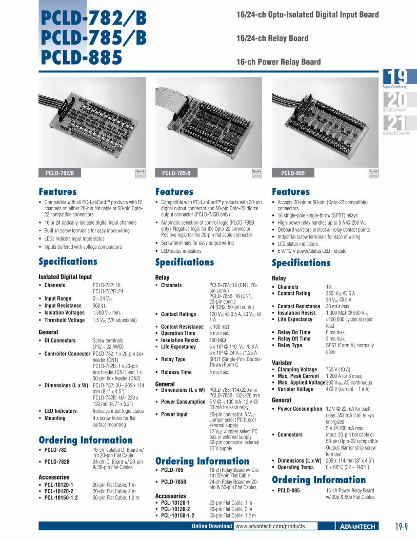
SpecificationsRelay Channels 16 Contact Rating 250 VAC @ 6 A
30 VDC @ 5 A Contact Resistance 30 mΩ max. Insulation Resist. 1,000 MΩ @ 500 VDC
Life Expectancy >100,000 cycles at rated load
Relay On Time 6 ms max. Relay Off Time 3 ms max. Relay Type SPST (Form A), normally
open
Varister Clamping Voltage 760 V (10 A) Max. Peak Current 1,200 A for 8 msec. Max. Applied Voltage 300 VRMS AC continuous Varistor Voltage 470 V (current = 1 mA)
General Power Consumption 12 V @ 22 mA for each
relay, 352 mA if all relays energized 5 V @ 200 mA max.
Connectors Input: 20-pin flat cable or 50-pin Opto-22 compatible Output: Barrier strip screw terminal
Dimensions (L x W) 205 x 114 mm (8" x 4.5") Operating Temp. 0 ~ 60°C (32 ~ 140°F)
Ordering Information PCLD-885 16-ch Power Relay Board
w/ 20p & 50p Flat Cables
16/24-ch Opto-Isolated Digital Input Board
16/24-ch Relay Board
16-ch Power Relay Board
PCLD-782/BPCLD-785/BPCLD-885
Features Compatible with all PC-LabCard™ products with DI
channels on either 20-pin flat cable or 50-pin Opto-22 compatible connectors
16 or 24 optically-isolated digital input channels
Built-in screw terminals for easy input wiring
LEDs indicate input logic status
Inputs buffered with voltage comparators
Features Compatible with PC-LabCard™ products with 20-pin
digital output connector and 50-pin Opto-22 digital output connector (PCLD-785B only)
Automatic selection of control logic (PLCD-785B only): Negative logic for the Opto-22 connector Positive logic for the 20-pin flat cable connector
Screw terminals for easy output wiring
LED status indicators
Features Accepts 20-pin or 50-pin (Opto-22 compatible)
connectors 16 single-pole single-throw (SPST) relays High-power relay handles up to 5 A @ 250 VAC
Onboard varistors protect all relay contact points Industrial screw terminals for ease of wiring LED status indicators 5 V/ 12 V power/status LED indicator
PCLD-782/B PCLD-785/B PCLD-885RoHSCOMPLIANT2002/95/EC
RoHSCOMPLIANT2002/95/EC
RoHSCOMPLIANT2002/95/EC

Signal Conditioning Modules and Terminal Boards19-10
PCLD-8751 PCLD-8761 PCLD-8762
PCLD-8751 PCLD-8761 PCLD-8762
48-ch Opto-Isolated Digital Input Board
24-ch Opto-Isolated DI and 24-ch Relay Output Board
48-ch Relay Output Board
Features 48 optically-isolated digital input channels
Built-in plug-in screw terminals for easier wiring
LEDs indicate input logic status
Input buffered with voltage comparators
Wet/Dry contact set by DIP switches
Input logic set by jumper
Wide input range from 5 to 30 V
SpecificationsDigital Input Channels 48 isolated digital inputs Contact Mode Wet contact
Dry contact (set by switch) Isolation Voltage 3,500 V Logic Modes Positive Logic
Negative Logic (set by jumper)
Signal Voltage 0 ~ 30 V VIH (MIN) : 4 V, VIL (MAX) : 1 V
General Certification CE, FCC Connectors Cable: SCSI-68 pin
Signals: Plug-in screw terminals (#14 - 24 AWG)
Dimensions 255 x 121 mm (10.04" x 4.76")
LED Indicators One for each channel to indicate logic status
Mounting DIN-rail
Ordering Information PCLD-8751 48-ch Opto-isolated Digital
Input Board
Features Built-in plug-in screw terminals for easier wiring
LED status indicators for Relay output
DIN-rail mounting
Onboard relay driver circuits
SpecificationsRelay Output Contact Rating 30 VDC @ 1 A,
120 VAC @ 0.5 A Contact Resistance < 100 W Electrical Endurance 5 x 10⁷ times at 12 V/10
mA Mechanical 108 times
Endurance Operation Time 5 ms Max Release Time 6 ms Max
General Certification CE, FCC Connectors
Cable: SCSI-68 pin Signals: Plug-in screw terminals (#14 - 24 AWG)
Dimensions 285 x 117 mm (11.22" x 4.61")
Mounting DIN-rail Power Input Unregulated 7 ~ 30 VDC
Power Consumption 7 V @ 1.8 A, 30 V @ 0.45 A (External power supply is required)
Ordering Information PCLD-8762 48-ch Relay (SPDT) Output
Board
Features Built-in plug-in screw terminals for easier wiring LED status indicators for D/I and relay output Digital inputs buffered with voltage comparators Wet/Dry contact set by DIP switches for D/I Wide input range from 5 to 30 V INT/EXT Power selection by jumper
SpecificationsDigital Input Channels 24 IDI with LED and 24 Relay
(SPDT) Form C with LED Contact Mode Wet contact and dry contact for
each IDI (set by switch) Digital Input 0 ~ 30 V VIH (MIN) : 4 V, VIL
(MAX) : 1V Isolation Voltage 3,500 V (Isolated DI), 1,500V
(Relay) Logic Mode Positive Logic
(IDI and Relay are Negative Logic independent) (set by jumper)
Relay Output Contact Rating 30 VDC @ 1 A,
120 VAC @ 0.5 A Contact Resistance < 100 W Electrical Endurance 5 x 10⁷ times at 12 V/10 mA Mechanical 108 times
Endurance Operation Time 5 ms Max Release Time 6 ms Max
General Certification CE, FCC Connectors
Cable: SCSI-68 pin Signals: Plug-in screw terminals (#14 - 24 AWG)
Dimensions 285 x 121 mm (11.22" x 4.76")
Mounting DIN-rail Power Consumption +5 V @ < 380 mA +50*n (mA)
+12 V @ < 240 mA +70*n (mA) (*n indicate the number of relays)
Power Selection PCI Bus or External power (7 ~ 30 V) by jumper
Ordering Information PCLD-8761 24-ch Opto-isolated DI and
24-ch Relay (SPDT) Output Board

www.advantech.com/productsOnline Download 19-11
Signal Conditioning19
USB DAQ Modules20
CompactPCI Systems21
PCLD-786PCLD-7216
8-ch SSR I/O Module Carrier Board
16-ch SSR I/O Module Carrier Board
Features Up to eight AC or DC solid state relay modules Photo-coupler isolated operation Eight external relay drivers LED status indicators
SpecificationsAC Solid State Relays 1 Cycle Surge 40 A Blocking Voltage ±600 V min. Off Leakage Current 8 mA max. On-state Voltage 1.6 V max. Output Rating 24 ~ 280 VAC @ 3.0 A Turn On zero volts Turn On/Turn Off Time < ½ cycle Type PCLM-OAC5A
DC Solid State Relays 1 Second Surge 5 A OFF Leakage Current 1 mA max. ON-state Voltage 1.4 V max. Output Rating 5 ~ 60 VDC @ 3.0 A Turn On/Turn Off Time 750 µs max. Type PCLM-ODC5
External Relay Drivers Channels 8 Coil Driving Voltage 5 V, 12 V from PC or external source Driver Type ULN2003, open collector type Max. Driving Current 125 mA each channel
General Dimensions (L x W) 205 x 114 mm (8.1" x 4.5")
Ordering Information PCLD-786 8-ch SSR I/O Module Board w/ 20-pin Flat Cable
Note: PCLD-786 does not include SSRs. They must be ordered by selecting single piece SSR modules according to your requirements.
PCLM-OAC5A Single Piece AC SSR Module (280 VAC, 3 A) PCLM-ODC5 Single Piece DC SSR Module (60 VDC, 3 A)
PCL-10120-1
Features Channel status reflected by onboard LED for easy monitoring Onboard fuse protection
SpecificationsModule Type Field Side Logic Side
Output Modules Part No. Output Voltage Rating
Output Current Rating
Input Logic and SSR Status
AC Output PCLM-OAC5A24 ~ 280 VAC
3.0 ATTL low (On)
12 ~ 280 VAC TTL high (Off)
DC Output PCLM-ODC5 5 ~ 60 VAC 3.0 ATTL low (On)TTL high (Off)
Input Modules Part No. Input On Voltage Input Off Voltage Output Logic and On/Off Status
AC Input PCLM-IAC5A 180 ~ 280 VAC < 80 VTTL low (On)TTL high (Off)
DC Input PCLM-IDC5B 3 ~ 32 VAC < 1 VTTL low (On)TTL high (Off)
Input ModulesField Side: Input On/Off PCLM-IAC5: 90 ~ 140 V/45 VRMS
Voltage Range PCLM-IAC5A: 180 ~ 280 V/80 VRMS PCLM-IDC5B: 3 ~ 32 V/1 VDC
Input Resistance PCLM-IAC5: 14 kΩ, PCLM-IAC5A: 44 kΩ, PCLM-IDC5B: 1.5 kΩ
Turn On/Off Time PCLM-IAC5: 20 msec. max., PCLM-IAC5A: 20 msec. max. PCLM-IDC5B: 100 msec. max.
Logic Side: Breakdown Voltage 30 VDC
Output Current 100 mA max. Output Voltage Drop 0.4 V max. Supply Current 12 mA max. Supply Voltage 4 ~ 6 V
Output ModulesField Side: Current Rating 3 A max. (@ 25°C) Contact Voltage Drop 1.6 V max. Turn On/Off Time PCLM-OAC series: ½ AC cycle max.
PCLM-ODC series: 100 µsec/750 µsec. max.Logic Side: Input Resistance 220 Ω Supply Voltage 4 ~ 6 V Supply Current 12 mA max.
General Logic Side Connectors 50-pin edge connector, Opto-22 compatible Dimensions (L x W x H) 367 x 111 x 56 mm (14.4" x 4.4" x 2.2")
Ordering Information PCLD-7216 16-ch SSR I/O Module Carrier Board
Note: PCLD-7216 does not include SSRs. They must be ordered by selecting single piece SSR modules according to your requirements.
PCLD-7216PCLD-786 PCLM-ODC5

Signal Conditioning Modules and Terminal Boards
Features
PCLD-8710 PCLD-8712
IntroductionThe PCLD-8710 is designed to match multifunction cards with 68-pin SCSI-II connectors, such as the PCI-1710U/UL, PCI-1710HGU, PCI-1711U/UL, PCI-1716/L cards. This screw-terminal board also includes cold junction sensing circuitry that allows direct measurements from thermocouple transducers. Together with software compensation and linearization, every thermocouple type can be accommodated. The PCLD-8712 Screw-terminal Board provides convenient and reliable signal wiring for the PCI-1712/L of which has a 68-pin SCSI-II connector.
Due to its special PCB layout you can install passive components to construct your own signal-conditioning circuits. The user can easily construct a low-pass filter, attenuator or current shunt converter by adding resistors and capacitors on board’s circuit pads.
ApplicationsField wiring for analog and digital I/O channels of PC-LabCard™ products.
Signal conditioning circuits can be implemented as illustrated in the following examples:
a) Straight-through connection (factory setting) RAn = 0 W (short)
RBn = none
Cn = none
c) 10 : 1 voltage attenuator: RAn = 9 KW
RBn = 1 KW
Cn = none
Attenuation =
(Assume source impedance << 10 KW)
d) 4 ~ 20 mA to 1 ~ 5 VDC signal converter: RAn = 0 W (short)
RBn = 250 W (0.1% precision resistor)
Cn = none
Ordering Information PCLD-8710 DIN-rail Wiring Terminal Board with CJC Circuit PCLD-8712 DIN-rail Wiring Terminal for PCI-1712/L PCL-10120-1 20-pin Flat Cable, 1 m PCL-10120-2 20-pin Flat Cable, 2 m PCL-10168-1 68-pin SCSI Shielded Cable, 1 m PCL-10168-2 68-pin SCSI Shielded Cable, 2 m
b) 1.6 kHz (3 dB) low pass filter RAn = 10 KW
RBn = none
Cn = 0.01 µF
f3dB =
f3dB =
19-12
PCLD-8710 PCLD-8712
DIN-rail Wiring Terminal Board with CJC Circuit
DIN-rail Wiring Terminal for PCI-1712/L
Low-cost screw-terminal with 68-pin SCSI-II connector
Onboard CJC (Cold Junction Compensation) circuits for direct thermocouple measurement (PCLD-8710)
Reserved space for signal-conditioning circuits such as low-pass filter, voltage attenuator and current shunt
Industrial-grade screw-clamp terminal blocks for heavy-duty and reliable connections
DIN-rail mounting case for easy mounting
Supports PCI-1710U/UL, PCI-1710HGU, PCI-1711U/UL, PCI-1716/L (PCLD-8710) and PCI-1712/1712L (PCLD-8712)

www.advantech.com/productsOnline Download
Features
PCLD-788 16-ch Relay Multiplexer Board
SpecificationsI/O Channel Closed Signal TTL-level pulse Cold-junction Sensor 24.4 mV/°C, 0 V at 0°C
Output Contact Rating Break-before-make with 3 msec. minimum break time Contact Resistance 200 mΩ max. Input Channels 16 isolated differential inputs Programming DO bit 0, 1, 2 and 3 for channel selection, DO bit 4, 5,
6 and 7 for board selection. Onboard DIP switches for board-address setting
Max. Input Voltage 100 VDC or 100 V peak AC Max. Switching Current 0.5 A Max. Switching Power 10 VA Operating Time 1 ms max. Relay Life Expectancy 100 million cycles min. at 10 VDC and 1 mA Release Time 1 msec. max.
General Connectors
Controller: 2 x 20-pin box header, second connector in parallel for daisy chaining I/O: Screw terminals
Dimensions (L x W) 205 x 114 mm (8" x 4.5") Mounting 4 x screw holes for flat surface mounting Power Consumption 5 V @ 380 mA max.
PCLD-788 Block Diagram
16 to 1 channel expansion
Differential and fully isolated multiplexing
Break-before-make relay control
“Channel closed” signal for precise A/D triggering
Up to 16 PCLD-788s can be cascaded for 256 channels
Easy wiring for large channel count configuration
Onboard cold-junction circuitry for thermocouple measurement
Pin Assignments
IntroductionPCLD-788 multiplexes 16 channels into a single I/O channel of an A/D converter, voltmeter or IEEE-488-based instrument. Up to 16 PCLD-788s can be cascaded for a total of 256 fully-isolated differential channels. The PCLD-788 can be controlled by any PC-LabCard™ product via a 16-bit 20-pin digital output port, found on cards such as the PCL-711B, PCL-812PG or the PCL-818 series. Channel selection (0-15) and board selection (0-15) are done by programming the high-order four bits and low order four bits of a digital output byte from the main I/O card in use.
Ordering Information PCLD-788 16-ch Relay MUX Board w/ Two 20-pin Flat Cables PCL-10120-1 20-pin Flat Cable, 1 m PCL-10120-2 20-pin Flat Cable, 2 m
19-13
Signal Conditioning19
USB DAQ Modules20
CompactPCI Systems21

Signal Conditioning Modules and Terminal Boards
Features
SpecificationsI/O Cold-junction 24.4 mV/°C, 0 V at 0°C
Compensation Input Channels 16 differential Input Conditions
Gains CMRR Nonlinearity Setting Time1,000 125 dB 0.005% FSR 75 µsec.100 115 dB 0.005% FSR 15 µsec.10 105 dB 0.007% FSR 15 µsec.1 85 dB 0.015% FSR 15 µsec.
Input Range ±10 V max. depending on the selected gain Output Range ±10 V max. Overvoltage Protection ±30 V continuous
General Connectors
Controller: 1 x DB37 male connector 2 x 20-pin box header for daisy chaining I/O: Screw terminals
Dimensions (L x W) 205 x 114 mm (8.1" x 4.5") Mounting 4 x screw holes for flat surface mounting Power Consumption 5 V @ 30 mA max, 12 V @ 80 mA max.
Ordering Information PCLD-789D Amplifier and Multiplexer Board w/ 1m DB37 Cable PCL-10137-1 DB37 Cable, 1 m PCL-10137-2 DB37 Cable, 2 m PCL-10137-3 DB37 Cable, 3 m PCL-10120-1 20-pin Flat Cable, 1 m PCL-10120-2 20-pin Flat Cable, 2 m
PCLD-789D Amplifier and Multiplexer Board
Multiplexes 16 differential inputs to one A/D input
Expands a PC-LabCard™ product’s analog inputs to 128 channels
High-grade instrumentation amplifier provides switch selectable gains of 1, 2, 10, 50, 100, 200, 1,000
Onboard cold-junction compensation circuits for direct thermocouple measurement
Built-in signal conditioning functions include filter, attenuator and current shunt
Second connectors onboard allow daisy chaining
Screw-clamp terminal blocks permit easy and reliable connections
Block Diagram
Pin Assignments
IntroductionPCLD-789D is a front-end signal conditioning and channel multiplexing daughterboard for use with PC-LabCard™ product’s analog input ports. It multiplexes 16 differential input channels into a single A/D converter input channel. You can cascade up to ten PCLD-789Ds, allowing a single data acquisition card to access 160 analog input channels.
PCLD-789D has DB37 and 20-pin flat cable connectors and lets your PCL-818L or PCL-818HD access up to 128 channels without using an additional digital output cable to select channels. The PCLD-789D uses a high-grade instrumentation amplifier that provides switch-selectable gains of 1, 2, 10, 50, 100, 200 and 1,000. This amplifier lets you accurately measure low-level signals with your PC-LabCard™ product. The board also contains a cold-junction sensing circuit that allows direct temperature measurement from thermocouple transducers. A wide variety of thermocouples are supported with software compensation and linearization.
19-14