Embed Size (px)
Citation preview
SIGMA® PRIMARY KNEE SYSTEMClassic Surgical Technique
INSTRUMENTS
INSTRUMENTS
RPF
DUOFIX
SURGICAL TECHNIQUE

Contemporary total knee arthroplasty demands high performance instrumentation that provides enhanced efficiency, precision, and flexibility. Through a program of continuous development DePuy Synthes Joint Reconstruction, a division of DePuy Orthopaedics, Inc., now offers a single system of High Performance instruments that supports your approach to knee replacement surgery.
This surgical technique provides instruction on the implantation of the SIGMA® Family of Fixed Bearing and Rotating Platform Knees utilizing the Classic femoral preparation system.
There are several approach options available to the surgeon, the most common are: medial parapatellar, mini-midvastus and mini-subvastus.

Surgical Summary 2
Incision and Exposure 4
Patella Resection 7
Femoral Alignment 10
Distal Femoral Resection 14
Tibial Jig Assembly 16
Lower Leg Alignment 17
Tibial Resection 20
Extension Gap Assessment and Balancing 22
Femoral Sizing 23
Femoral Rotation 25
Anterior Down/Posterior Up Sizing Guides 26
Femoral Preparation - A/P and Chamfer Cuts 27
Femoral Resection - Notch Cuts 28
Trial Components (For Fixed Bearing, see Appendix A) 29
Tibial Preparation - MBT 32
Final Patella Preparation 34
Cementing Technique 35
Final Component Implantation 36
Closure 38
Appendix A: Fixed Bearing Modular Tibial Preparation 39
Appendix A: Fixed Bearing Standard Tibial Preparation 43
Appendix B: Tibial I.M. Jig Alignment 44
Appendix C: Spiked Uprod 47
Ordering Information 50
SURGICAL TECHNIQUE
SIGMA® Primary Knee System Classic Surgical Technique DePuy Synthes Joint Reconstruction
TABLE OF CONTENTS
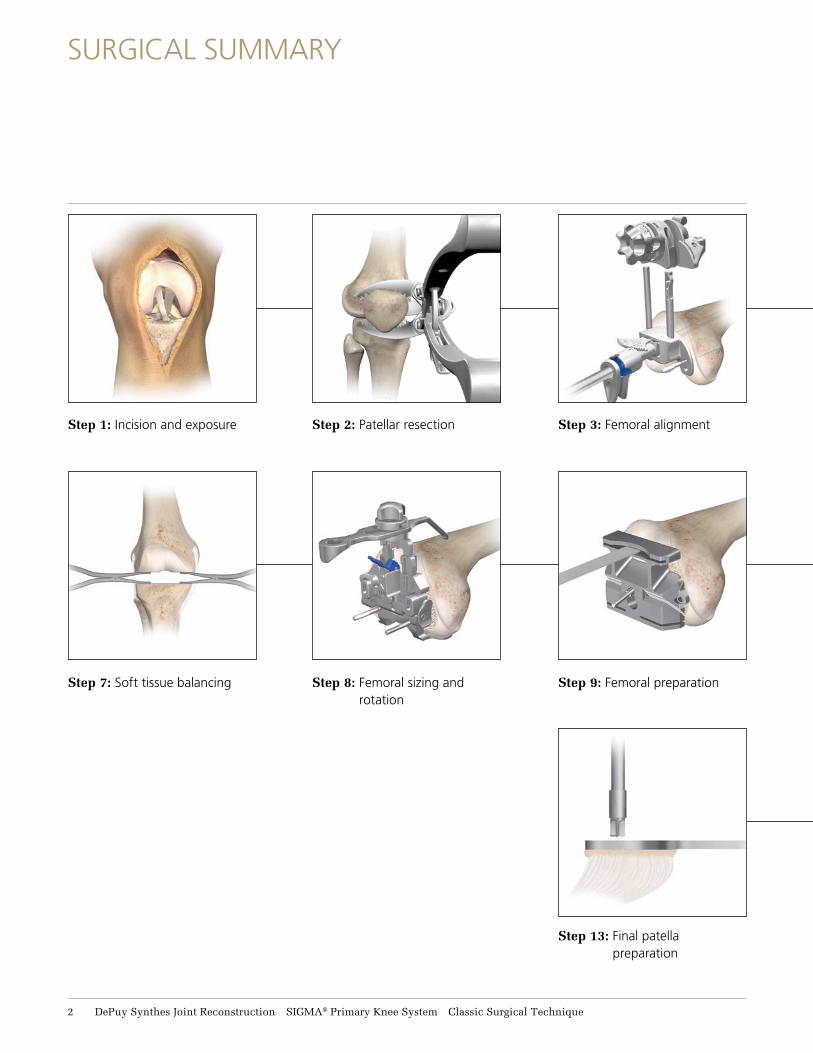
Step 1: Incision and exposure
Step 7: Soft tissue balancing Step 8: Femoral sizing and rotation
Step 9: Femoral preparation
Step 13: Final patella preparation
Step 2: Patellar resection Step 3: Femoral alignment
SURGICAL SUMMARY
2 DePuy Synthes Joint Reconstruction SIGMA® Primary Knee System Classic Surgical Technique
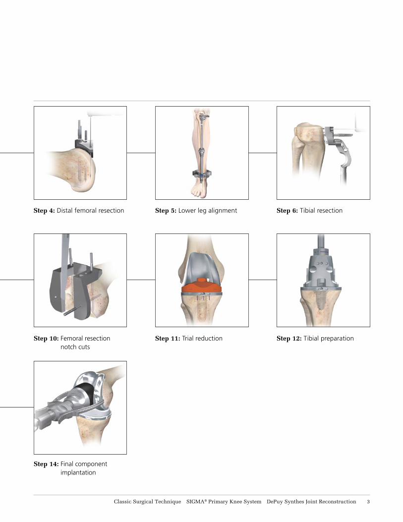
Step 10: Femoral resection notch cuts
Step 11: Trial reduction Step 12: Tibial preparation
Step 14: Final component implantation
Step 4: Distal femoral resection Step 5: Lower leg alignment Step 6: Tibial resection
Classic Surgical Technique SIGMA® Primary Knee System DePuy Synthes Joint Reconstruction 3
The SIGMA® High Performance instrumentation is designed for use with and without Ci™ Computer Assisted Surgery, for both open and minimal invasive approaches to the knee.
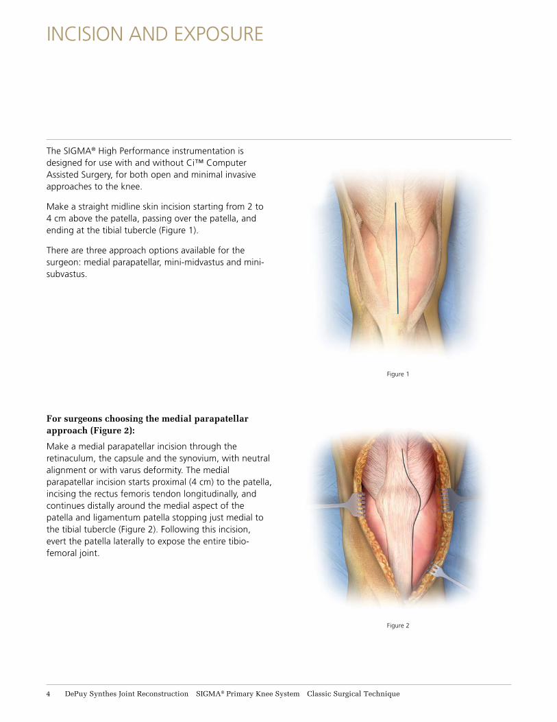
Make a straight midline skin incision starting from 2 to 4 cm above the patella, passing over the patella, and ending at the tibial tubercle (Figure 1).
There are three approach options available for the surgeon: medial parapatellar, mini-midvastus and mini-subvastus.
For surgeons choosing the medial parapatellar approach (Figure 2):
Make a medial parapatellar incision through the retinaculum, the capsule and the synovium, with neutral alignment or with varus deformity. The medial parapatellar incision starts proximal (4 cm) to the patella, incising the rectus femoris tendon longitudinally, and continues distally around the medial aspect of the patella and ligamentum patella stopping just medial to the tibial tubercle (Figure 2). Following this incision, evert the patella laterally to expose the entire tibio-femoral joint.
INCISION AND EXPOSURE
Figure 2
Figure 1
4 DePuy Synthes Joint Reconstruction SIGMA® Primary Knee System Classic Surgical Technique
INCISION AND EXPOSURE
Figure 3
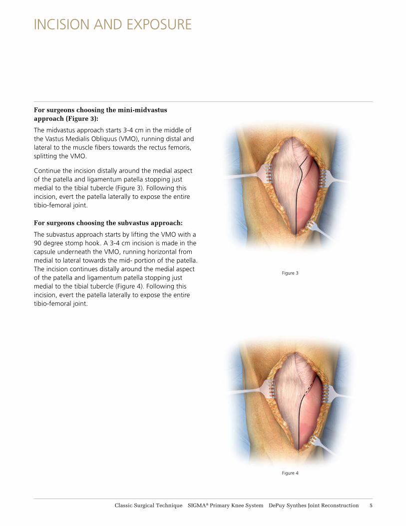
For surgeons choosing the mini-midvastus approach (Figure 3):
The midvastus approach starts 3-4 cm in the middle of the Vastus Medialis Obliquus (VMO), running distal and lateral to the muscle fibers towards the rectus femoris, splitting the VMO.
Continue the incision distally around the medial aspect of the patella and ligamentum patella stopping just medial to the tibial tubercle (Figure 3). Following this incision, evert the patella laterally to expose the entire tibio-femoral joint.
For surgeons choosing the subvastus approach:
The subvastus approach starts by lifting the VMO with a 90 degree stomp hook. A 3-4 cm incision is made in the capsule underneath the VMO, running horizontal from medial to lateral towards the mid- portion of the patella. The incision continues distally around the medial aspect of the patella and ligamentum patella stopping just medial to the tibial tubercle (Figure 4). Following this incision, evert the patella laterally to expose the entire tibio-femoral joint.
Figure 4
Classic Surgical Technique SIGMA® Primary Knee System DePuy Synthes Joint Reconstruction 5
INCISION AND EXPOSURE
Figure 5
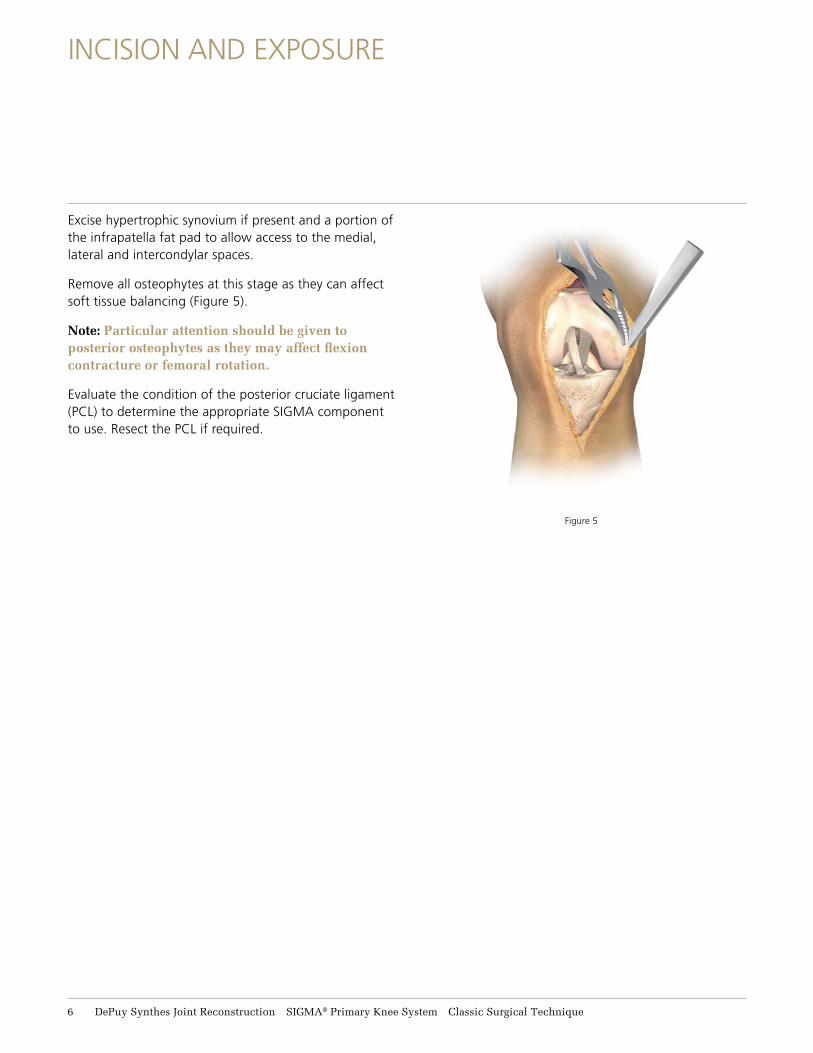
Excise hypertrophic synovium if present and a portion of the infrapatella fat pad to allow access to the medial, lateral and intercondylar spaces.
Remove all osteophytes at this stage as they can affect soft tissue balancing (Figure 5).
Note: Particular attention should be given to posterior osteophytes as they may affect flexion contracture or femoral rotation.
Evaluate the condition of the posterior cruciate ligament (PCL) to determine the appropriate SIGMA component to use. Resect the PCL if required.
6 DePuy Synthes Joint Reconstruction SIGMA® Primary Knee System Classic Surgical Technique
PATELLA RESECTION
Resection and preparation of the patella can be performed sequentially or separately, as desired, and can be performed at any time during surgery.
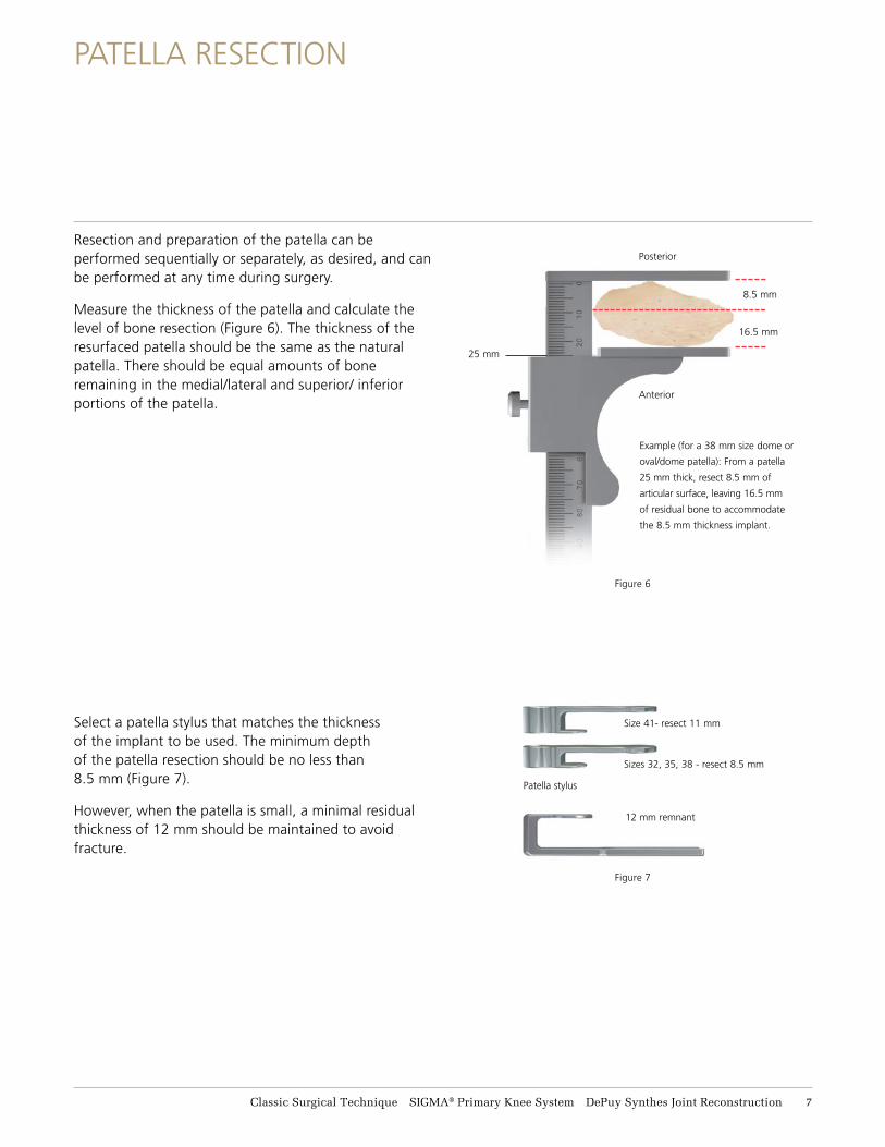
Measure the thickness of the patella and calculate the level of bone resection (Figure 6). The thickness of the resurfaced patella should be the same as the natural patella. There should be equal amounts of bone remaining in the medial/lateral and superior/ inferior portions of the patella.
Select a patella stylus that matches the thickness of the implant to be used. The minimum depth of the patella resection should be no less than 8.5 mm (Figure 7).
However, when the patella is small, a minimal residual thickness of 12 mm should be maintained to avoid fracture.
8.5 mm
16.5 mm
25 mm
Example (for a 38 mm size dome or
oval/dome patella): From a patella
25 mm thick, resect 8.5 mm of
articular surface, leaving 16.5 mm
of residual bone to accommodate
the 8.5 mm thickness implant.
Size 41- resect 11 mm
Sizes 32, 35, 38 - resect 8.5 mm
Posterior
Anterior
Figure 6
Figure 7
12 mm remnant
Patella stylus
Classic Surgical Technique SIGMA® Primary Knee System DePuy Synthes Joint Reconstruction 7
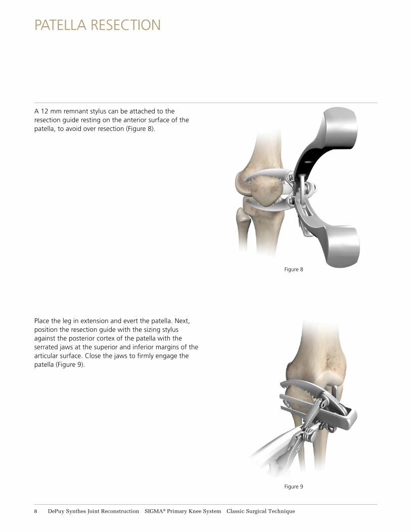
Figure 8
Figure 9
A 12 mm remnant stylus can be attached to the resection guide resting on the anterior surface of the patella, to avoid over resection (Figure 8).
Place the leg in extension and evert the patella. Next, position the resection guide with the sizing stylus against the posterior cortex of the patella with the serrated jaws at the superior and inferior margins of the articular surface. Close the jaws to firmly engage the patella (Figure 9).
PATELLA RESECTION
8 DePuy Synthes Joint Reconstruction SIGMA® Primary Knee System Classic Surgical Technique
PATELLA RESECTION
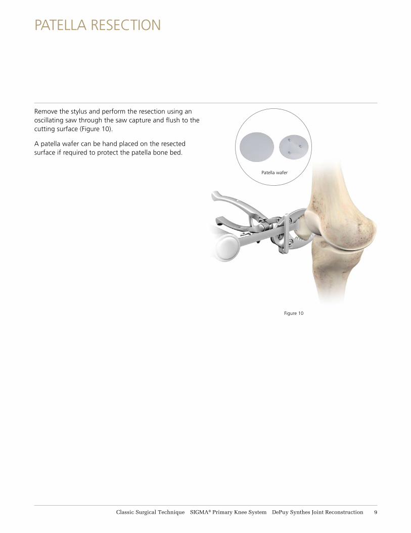
Remove the stylus and perform the resection using an oscillating saw through the saw capture and flush to the cutting surface (Figure 10).
A patella wafer can be hand placed on the resected surface if required to protect the patella bone bed.
Figure 10
Patella wafer
Classic Surgical Technique SIGMA® Primary Knee System DePuy Synthes Joint Reconstruction 9
FEMORAL ALIGNMENT
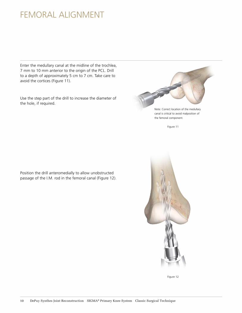
Enter the medullary canal at the midline of the trochlea, 7 mm to 10 mm anterior to the origin of the PCL. Drill to a depth of approximately 5 cm to 7 cm. Take care to avoid the cortices (Figure 11).
Use the step part of the drill to increase the diameter of the hole, if required.
Position the drill anteromedially to allow unobstructed passage of the I.M. rod in the femoral canal (Figure 12).
Figure 12
Note: Correct location of the medullary
canal is critical to avoid malposition of
the femoral component.
Figure 11
11 DePuy Synthes Joint Reconstruction SIGMA® Primary Knee System Classic Surgical Technique
FEMORAL ALIGNMENT
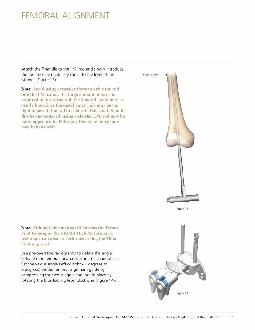
Isthmus level
Figure 13
Attach the T-handle to the I.M. rod and slowly introduce the rod into the medullary canal, to the level of the isthmus (Figure 13).
Note: Avoid using excessive force to drive the rod into the I.M. canal. If a large amount of force is required to insert the rod, the femoral canal may be overly bowed, or the distal entry hole may be too tight to permit the rod to center in the canal. Should this be encountered, using a shorter I.M. rod may be more appropriate. Enlarging the distal entry hole may help as well.
Note: Although this manual illustrates the Femur First technique, the SIGMA High Performance technique can also be performed using the Tibia First approach.
Use pre-operative radiographs to define the angle between the femoral, anatomical and mechanical axis. Set the valgus angle (left or right - 0 degrees to 9 degrees) on the femoral alignment guide by compressing the two triggers and lock in place by rotating the blue locking lever clockwise (Figure 14).
Figure 14
Classic Surgical Technique SIGMA® Primary Knee System DePuy Synthes Joint Reconstruction 11
FEMORAL ALIGNMENT
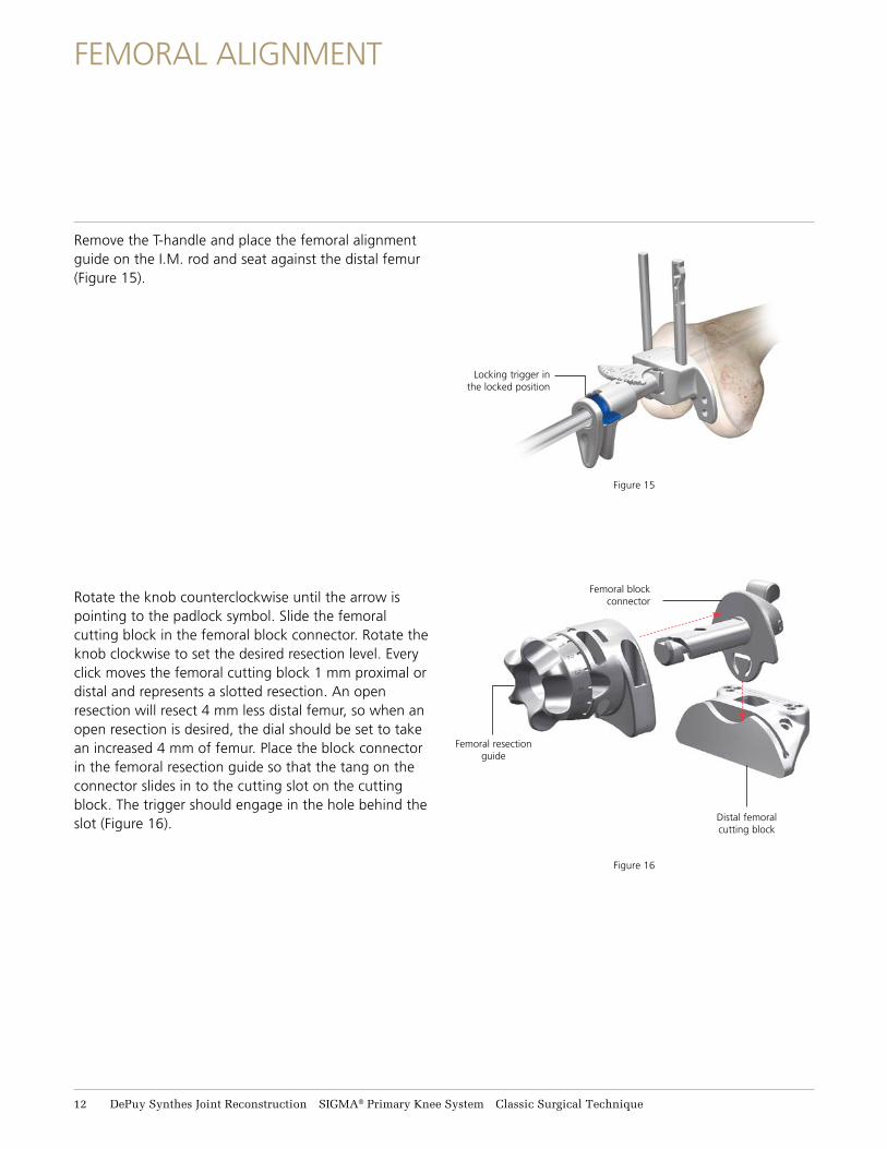
Remove the T-handle and place the femoral alignment guide on the I.M. rod and seat against the distal femur (Figure 15).
Rotate the knob counterclockwise until the arrow is pointing to the padlock symbol. Slide the femoral cutting block in the femoral block connector. Rotate the knob clockwise to set the desired resection level. Every click moves the femoral cutting block 1 mm proximal or distal and represents a slotted resection. An open resection will resect 4 mm less distal femur, so when an open resection is desired, the dial should be set to take an increased 4 mm of femur. Place the block connector in the femoral resection guide so that the tang on the connector slides in to the cutting slot on the cutting block. The trigger should engage in the hole behind the slot (Figure 16).
Figure 15
Locking trigger in the locked position
Distal femoral cutting block
Femoral block connector
Femoral resection guide
Figure 16
12 DePuy Synthes Joint Reconstruction SIGMA® Primary Knee System Classic Surgical Technique
FEMORAL ALIGNMENT
Distal femoral cutting block
Figure 17
Figure 18
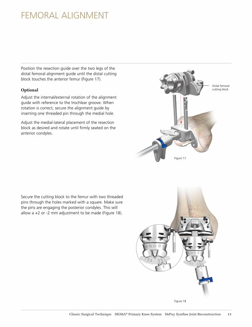
Position the resection guide over the two legs of the distal femoral alignment guide until the distal cutting block touches the anterior femur (Figure 17).
Optional
Adjust the internal/external rotation of the alignment guide with reference to the trochlear groove. When rotation is correct, secure the alignment guide by inserting one threaded pin through the medial hole.
Adjust the medial-lateral placement of the resection block as desired and rotate until firmly seated on the anterior condyles.
Secure the cutting block to the femur with two threaded pins through the holes marked with a square. Make sure the pins are engaging the posterior condyles. This will allow a +2 or -2 mm adjustment to be made (Figure 18).
Classic Surgical Technique SIGMA® Primary Knee System DePuy Synthes Joint Reconstruction 13
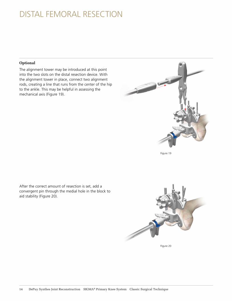
Figure 19
Optional
The alignment tower may be introduced at this point into the two slots on the distal resection device. With the alignment tower in place, connect two alignment rods, creating a line that runs from the center of the hip to the ankle. This may be helpful in assessing the mechanical axis (Figure 19).
After the correct amount of resection is set, add a convergent pin through the medial hole in the block to aid stability (Figure 20).
Figure 20
DISTAL FEMORAL RESECTION
14 DePuy Synthes Joint Reconstruction SIGMA® Primary Knee System Classic Surgical Technique
Release attachment
1. Slide femoral resection guide
upwards
2. Remove femoral alignment guide
towards the T-handle
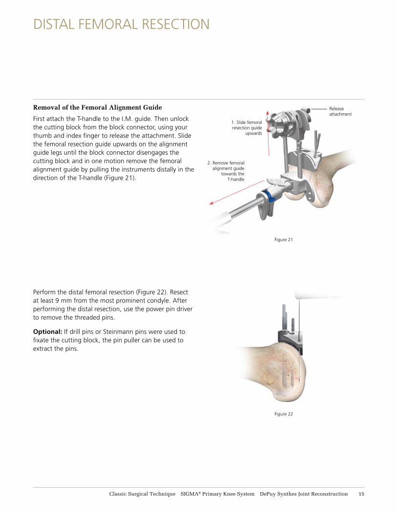
Removal of the Femoral Alignment Guide
First attach the T-handle to the I.M. guide. Then unlock the cutting block from the block connector, using your thumb and index finger to release the attachment. Slide the femoral resection guide upwards on the alignment guide legs until the block connector disengages the cutting block and in one motion remove the femoral alignment guide by pulling the instruments distally in the direction of the T-handle (Figure 21).
Perform the distal femoral resection (Figure 22). Resect at least 9 mm from the most prominent condyle. After performing the distal resection, use the power pin driver to remove the threaded pins.
Optional: If drill pins or Steinmann pins were used to fixate the cutting block, the pin puller can be used to extract the pins.
Figure 21
Figure 22
DISTAL FEMORAL RESECTION
Classic Surgical Technique SIGMA® Primary Knee System DePuy Synthes Joint Reconstruction 15
TIBIAL JIG ASSEMBLY
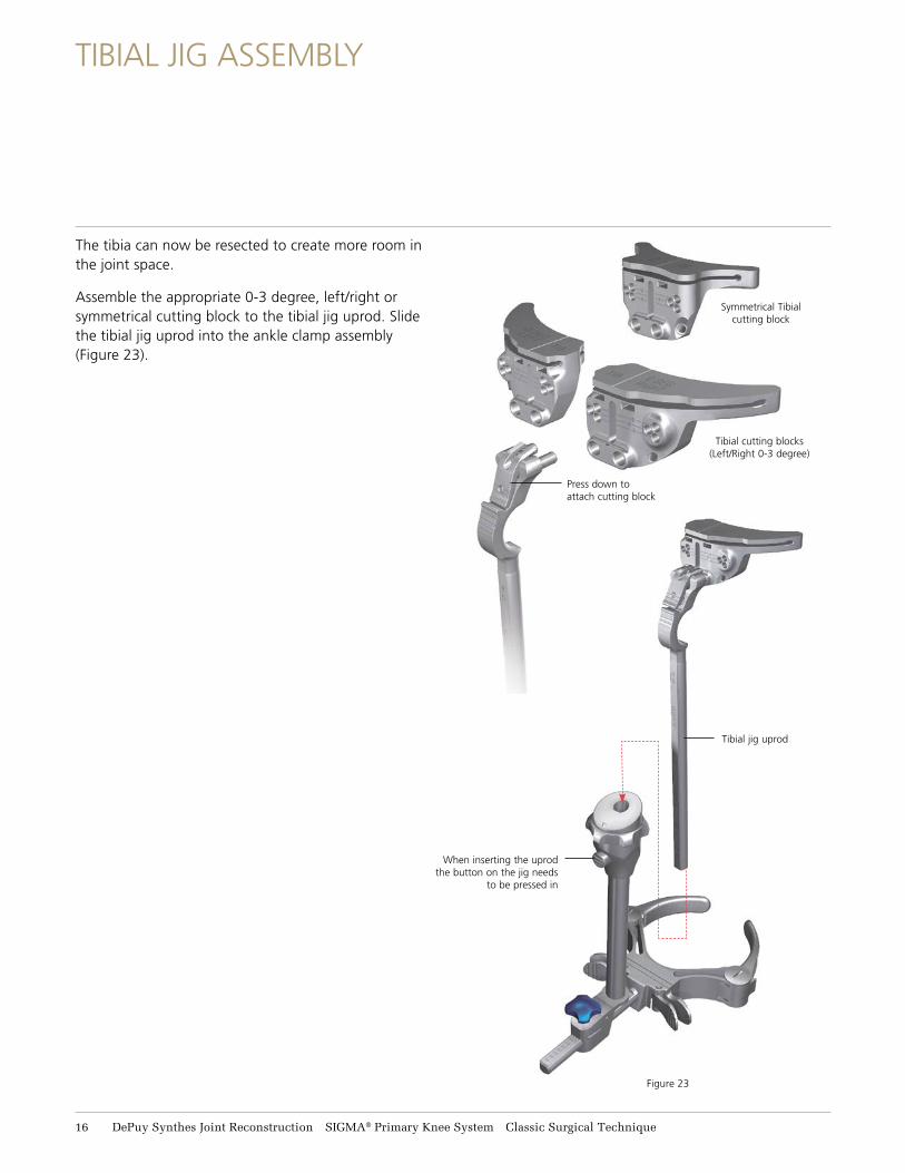
The tibia can now be resected to create more room in the joint space.
Assemble the appropriate 0-3 degree, left/right or symmetrical cutting block to the tibial jig uprod. Slide the tibial jig uprod into the ankle clamp assembly (Figure 23).
Tibial jig uprod
Figure 23
Tibial cutting blocks(Left/Right 0-3 degree)
Symmetrical Tibial cutting block
Press down to attach cutting block
When inserting the uprod the button on the jig needs
to be pressed in
16 DePuy Synthes Joint Reconstruction SIGMA® Primary Knee System Classic Surgical Technique
LOWER LEG ALIGNMENT
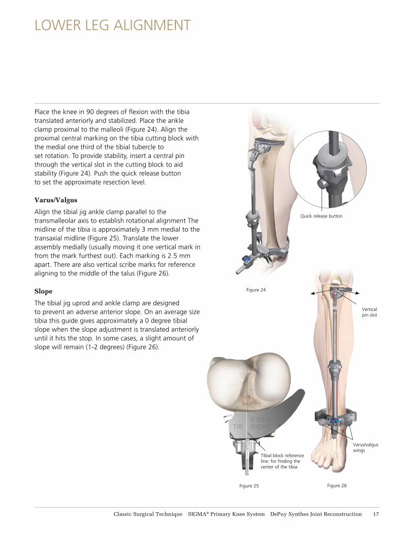
Place the knee in 90 degrees of flexion with the tibia translated anteriorly and stabilized. Place the ankle clamp proximal to the malleoli (Figure 24). Align the proximal central marking on the tibia cutting block with the medial one third of the tibial tubercle to set rotation. To provide stability, insert a central pin through the vertical slot in the cutting block to aid stability (Figure 24). Push the quick release button to set the approximate resection level.
Varus/Valgus
Align the tibial jig ankle clamp parallel to the transmalleolar axis to establish rotational alignment The midline of the tibia is approximately 3 mm medial to the transaxial midline (Figure 25). Translate the lower assembly medially (usually moving it one vertical mark in from the mark furthest out). Each marking is 2.5 mm apart. There are also vertical scribe marks for reference aligning to the middle of the talus (Figure 26).
Slope
The tibial jig uprod and ankle clamp are designed to prevent an adverse anterior slope. On an average size tibia this guide gives approximately a 0 degree tibial slope when the slope adjustment is translated anteriorly until it hits the stop. In some cases, a slight amount of slope will remain (1-2 degrees) (Figure 26).
Figure 24
Vertical pin slot
Varus/valgus wings
Quick release button
Figure 26Figure 25
Tibial block reference line: for finding the center of the tibia
Classic Surgical Technique SIGMA® Primary Knee System DePuy Synthes Joint Reconstruction 17
LOWER LEG ALIGNMENT
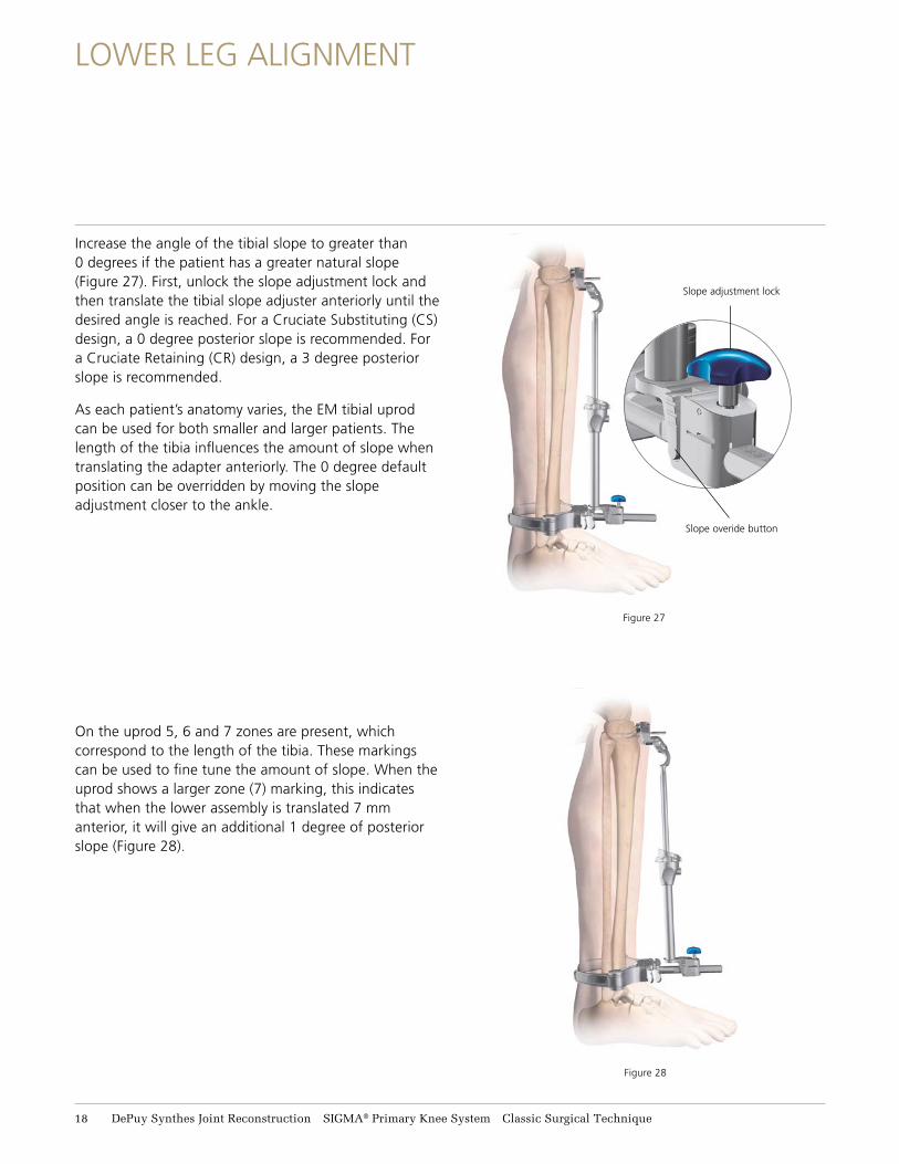
Increase the angle of the tibial slope to greater than 0 degrees if the patient has a greater natural slope (Figure 27). First, unlock the slope adjustment lock and then translate the tibial slope adjuster anteriorly until the desired angle is reached. For a Cruciate Substituting (CS) design, a 0 degree posterior slope is recommended. For a Cruciate Retaining (CR) design, a 3 degree posterior slope is recommended.
As each patient’s anatomy varies, the EM tibial uprod can be used for both smaller and larger patients. The length of the tibia influences the amount of slope when translating the adapter anteriorly. The 0 degree default position can be overridden by moving the slope adjustment closer to the ankle.
On the uprod 5, 6 and 7 zones are present, which correspond to the length of the tibia. These markings can be used to fine tune the amount of slope. When the uprod shows a larger zone (7) marking, this indicates that when the lower assembly is translated 7 mm anterior, it will give an additional 1 degree of posterior slope (Figure 28).
Figure 27
Figure 28
Slope overide button
Slope adjustment lock
18 DePuy Synthes Joint Reconstruction SIGMA® Primary Knee System Classic Surgical Technique
LOWER LEG ALIGNMENT
Figure 29
Fine tune adjustmentNon-slotted stylus foot
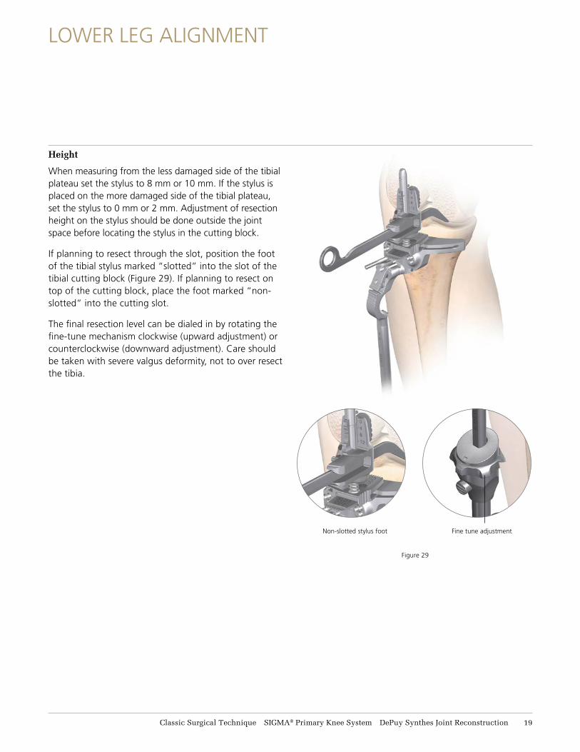
Height
When measuring from the less damaged side of the tibial plateau set the stylus to 8 mm or 10 mm. If the stylus is placed on the more damaged side of the tibial plateau, set the stylus to 0 mm or 2 mm. Adjustment of resection height on the stylus should be done outside the joint space before locating the stylus in the cutting block.
If planning to resect through the slot, position the foot of the tibial stylus marked “slotted” into the slot of the tibial cutting block (Figure 29). If planning to resect on top of the cutting block, place the foot marked “non-slotted” into the cutting slot.
The final resection level can be dialed in by rotating the fine-tune mechanism clockwise (upward adjustment) or counterclockwise (downward adjustment). Care should be taken with severe valgus deformity, not to over resect the tibia.
Classic Surgical Technique SIGMA® Primary Knee System DePuy Synthes Joint Reconstruction 19
TIBIAL RESECTION
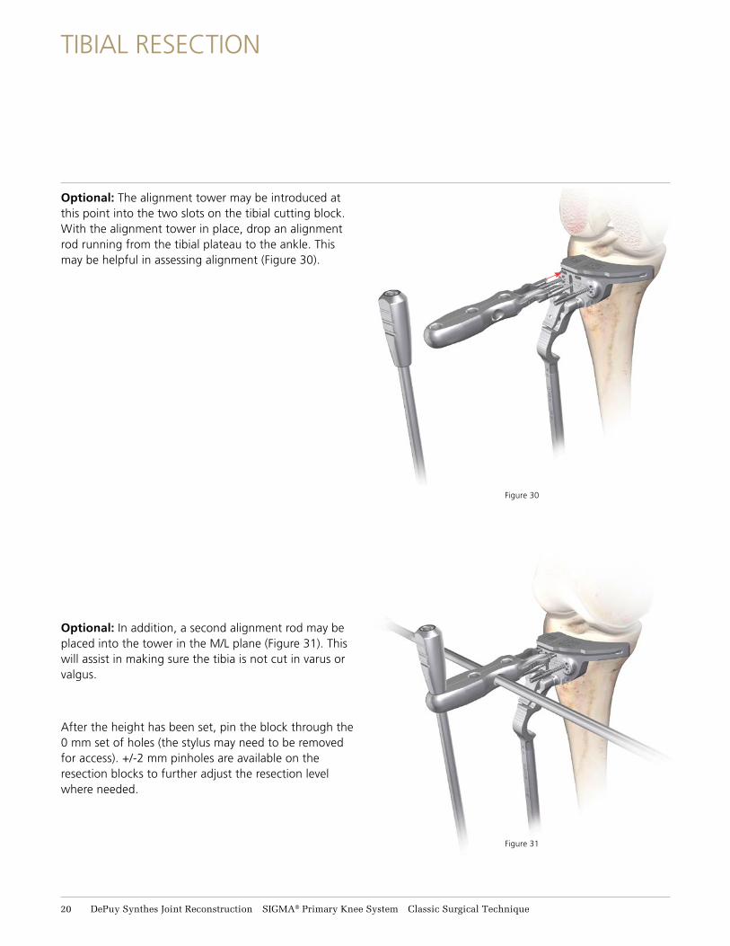
Optional: The alignment tower may be introduced at this point into the two slots on the tibial cutting block. With the alignment tower in place, drop an alignment rod running from the tibial plateau to the ankle. This may be helpful in assessing alignment (Figure 30).
Optional: In addition, a second alignment rod may be placed into the tower in the M/L plane (Figure 31). This will assist in making sure the tibia is not cut in varus or valgus.
After the height has been set, pin the block through the 0 mm set of holes (the stylus may need to be removed for access). +/-2 mm pinholes are available on the resection blocks to further adjust the resection level where needed.
Figure 30
Figure 31
21 DePuy Synthes Joint Reconstruction SIGMA® Primary Knee System Classic Surgical Technique
TIBIAL RESECTION
Figure 32
Classic Surgical Technique SIGMA® Primary Knee System DePuy Synthes Joint Reconstruction 21
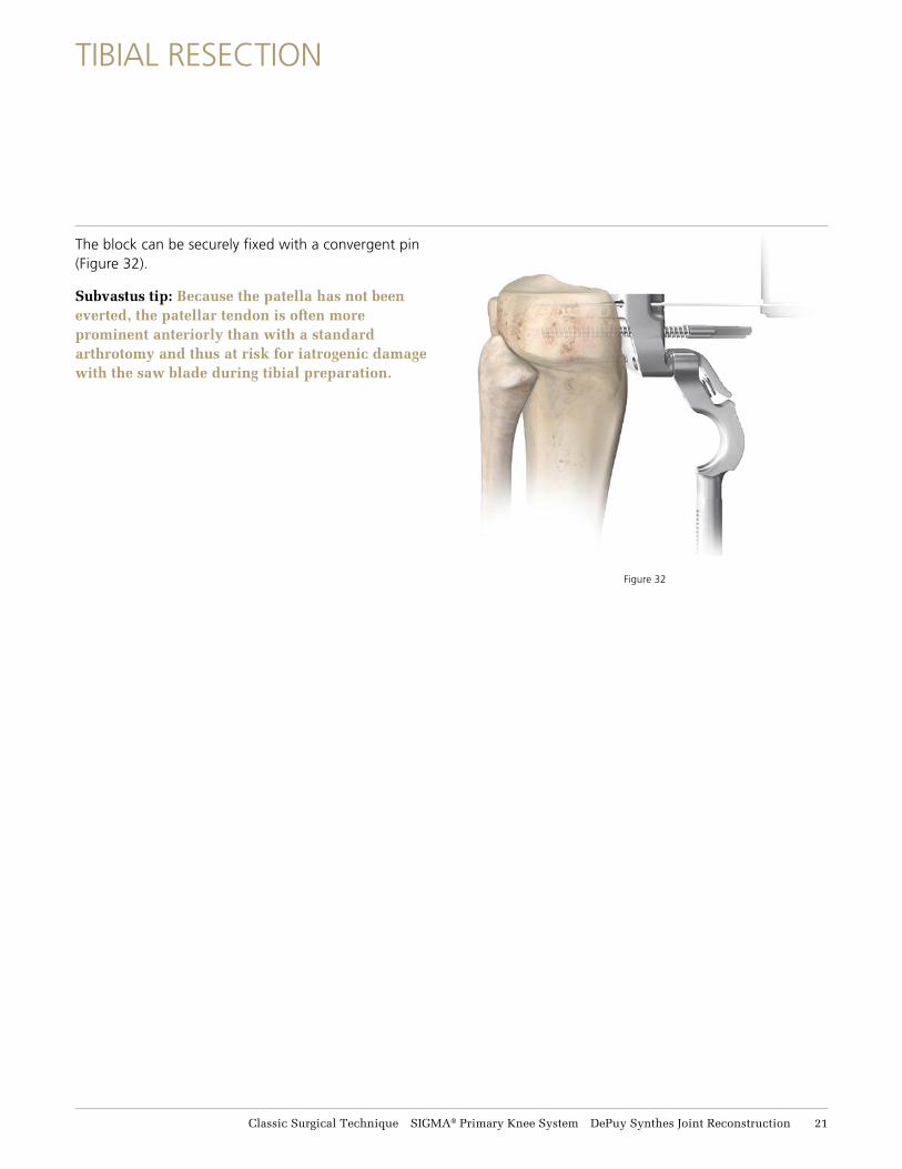
The block can be securely fixed with a convergent pin (Figure 32).
Subvastus tip: Because the patella has not been everted, the patellar tendon is often more prominent anteriorly than with a standard arthrotomy and thus at risk for iatrogenic damage with the saw blade during tibial preparation.
EXTENSION GAP ASSESSMENT AND BALANCING
Figure 34 Figure 35
Figure 33
Spacer block
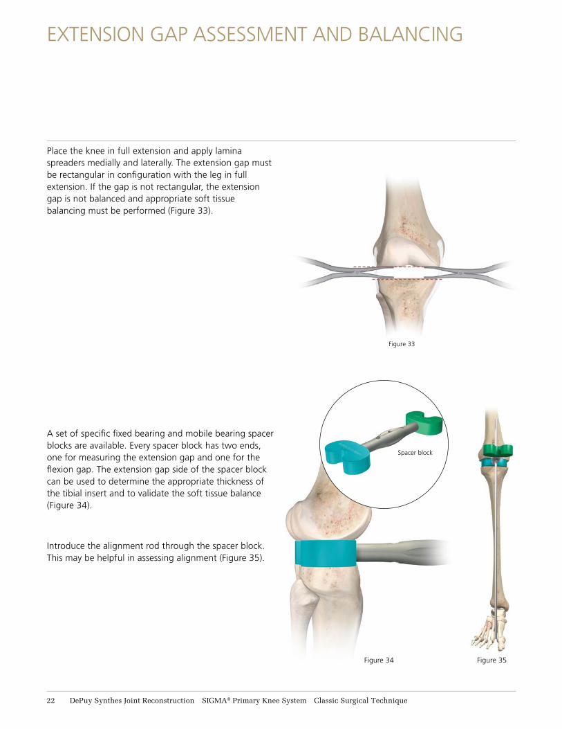
Place the knee in full extension and apply lamina spreaders medially and laterally. The extension gap must be rectangular in configuration with the leg in full extension. If the gap is not rectangular, the extension gap is not balanced and appropriate soft tissue balancing must be performed (Figure 33).
A set of specific fixed bearing and mobile bearing spacer blocks are available. Every spacer block has two ends, one for measuring the extension gap and one for the flexion gap. The extension gap side of the spacer block can be used to determine the appropriate thickness of the tibial insert and to validate the soft tissue balance (Figure 34).
Introduce the alignment rod through the spacer block. This may be helpful in assessing alignment (Figure 35).
22 DePuy Synthes Joint Reconstruction SIGMA® Primary Knee System Classic Surgical Technique
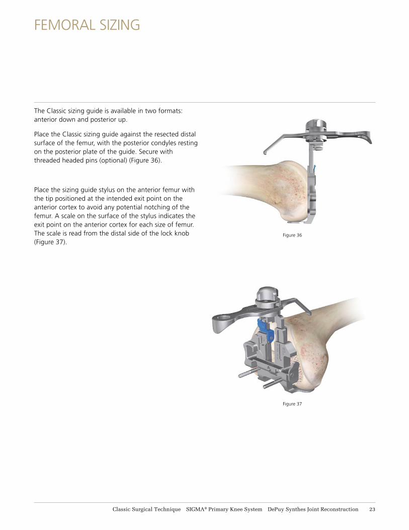
Figure 36
Figure 37
The Classic sizing guide is available in two formats: anterior down and posterior up.
Place the Classic sizing guide against the resected distal surface of the femur, with the posterior condyles resting on the posterior plate of the guide. Secure with threaded headed pins (optional) (Figure 36).
Place the sizing guide stylus on the anterior femur with the tip positioned at the intended exit point on the anterior cortex to avoid any potential notching of the femur. A scale on the surface of the stylus indicates the exit point on the anterior cortex for each size of femur. The scale is read from the distal side of the lock knob (Figure 37).
FEMORAL SIZING
Classic Surgical Technique SIGMA® Primary Knee System DePuy Synthes Joint Reconstruction 23
Size window Drill guide window
Figure 38
FEMORAL SIZING
24 DePuy Synthes Joint Reconstruction SIGMA® Primary Knee System Classic Surgical Technique
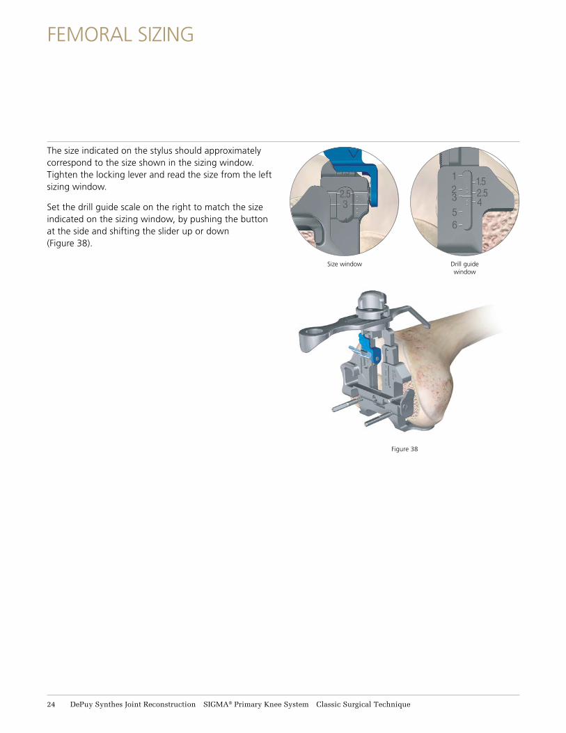
The size indicated on the stylus should approximately correspond to the size shown in the sizing window. Tighten the locking lever and read the size from the left sizing window.
Set the drill guide scale on the right to match the size indicated on the sizing window, by pushing the button at the side and shifting the slider up or down (Figure 38).
FEMORAL ROTATION
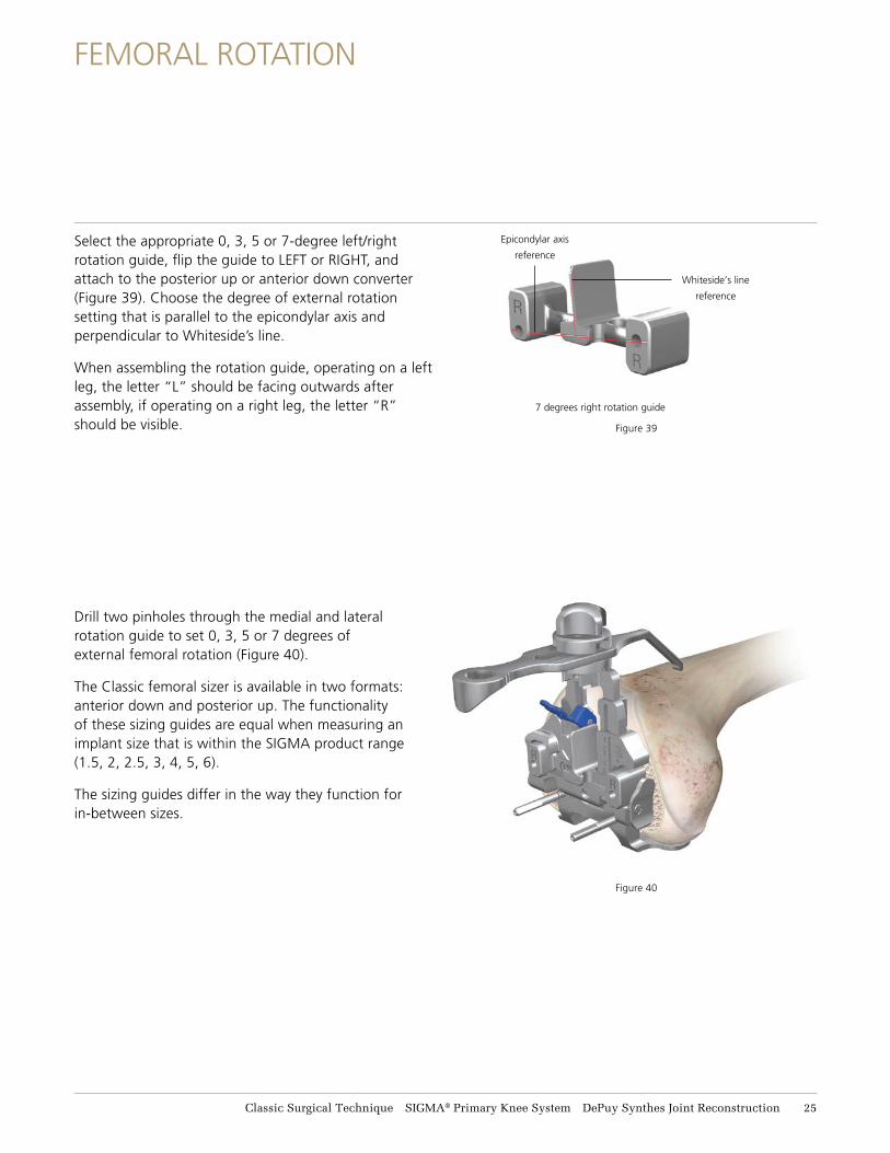
Select the appropriate 0, 3, 5 or 7-degree left/right rotation guide, flip the guide to LEFT or RIGHT, and attach to the posterior up or anterior down converter (Figure 39). Choose the degree of external rotation setting that is parallel to the epicondylar axis and perpendicular to Whiteside’s line.
When assembling the rotation guide, operating on a left leg, the letter “L” should be facing outwards after assembly, if operating on a right leg, the letter “R” should be visible.
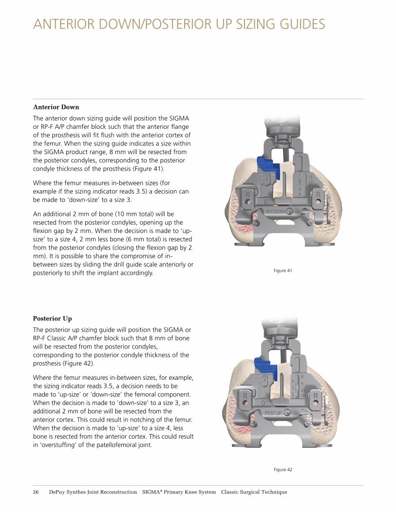
Drill two pinholes through the medial and lateral rotation guide to set 0, 3, 5 or 7 degrees of external femoral rotation (Figure 40).
The Classic femoral sizer is available in two formats: anterior down and posterior up. The functionality of these sizing guides are equal when measuring an implant size that is within the SIGMA product range (1.5, 2, 2.5, 3, 4, 5, 6).
The sizing guides differ in the way they function for in-between sizes.
Figure 40
Figure 39
7 degrees right rotation guide
Epicondylar axis
reference
Whiteside’s line
reference
Classic Surgical Technique SIGMA® Primary Knee System DePuy Synthes Joint Reconstruction 25
ANTERIOR DOWN/POSTERIOR UP SIZING GUIDES
Figure 41
Figure 42
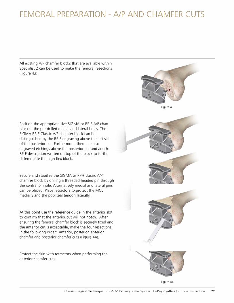
Anterior Down
The anterior down sizing guide will position the SIGMA or RP-F A/P chamfer block such that the anterior flange of the prosthesis will fit flush with the anterior cortex of the femur. When the sizing guide indicates a size within the SIGMA product range, 8 mm will be resected from the posterior condyles, corresponding to the posterior condyle thickness of the prosthesis (Figure 41).
Where the femur measures in-between sizes (for example if the sizing indicator reads 3.5) a decision can be made to ‘down-size’ to a size 3.
An additional 2 mm of bone (10 mm total) will be resected from the posterior condyles, opening up the flexion gap by 2 mm. When the decision is made to ‘up-size’ to a size 4, 2 mm less bone (6 mm total) is resected from the posterior condyles (closing the flexion gap by 2 mm). It is possible to share the compromise of in-between sizes by sliding the drill guide scale anteriorly or posteriorly to shift the implant accordingly.
Posterior Up
The posterior up sizing guide will position the SIGMA or RP-F Classic A/P chamfer block such that 8 mm of bone will be resected from the posterior condyles, corresponding to the posterior condyle thickness of the prosthesis (Figure 42).
Where the femur measures in-between sizes, for example, the sizing indicator reads 3.5, a decision needs to be made to ‘up-size’ or ‘down-size’ the femoral component. When the decision is made to ‘down-size’ to a size 3, an additional 2 mm of bone will be resected from the anterior cortex. This could result in notching of the femur. When the decision is made to ‘up-size’ to a size 4, less bone is resected from the anterior cortex. This could result in ‘overstuffing’ of the patellofemoral joint.
26 DePuy Synthes Joint Reconstruction SIGMA® Primary Knee System Classic Surgical Technique
FEMORAL PREPARATION - A/P AND CHAMFER CUTS
All existing A/P chamfer blocks that are available within Specialist 2 can be used to make the femoral resections (Figure 43).
Position the appropriate size SIGMA or RP-F A/P chamfer block in the pre-drilled medial and lateral holes. The SIGMA RP-F Classic A/P chamfer block can be distinguished by the RP-F engraving above the left side of the posterior cut. Furthermore, there are also engraved etchings above the posterior cut and another RP-F description written on top of the block to further differentiate the high flex block.
Secure and stabilize the SIGMA or RP-F classic A/P chamfer block by drilling a threaded headed pin through the central pinhole. Alternatively medial and lateral pins can be placed. Place retractors to protect the MCL medially and the popliteal tendon laterally.
At this point use the reference guide in the anterior slot to confirm that the anterior cut will not notch. After ensuring the femoral chamfer block is securely fixed and the anterior cut is acceptable, make the four resections in the following order: anterior, posterior, anterior chamfer and posterior chamfer cuts (Figure 44).
Protect the skin with retractors when performing the anterior chamfer cuts.
Figure 43
Figure 44
Classic Surgical Technique SIGMA® Primary Knee System DePuy Synthes Joint Reconstruction 27
FEMORAL RESECTION - NOTCH CUTS
Figure 45
Figure 46
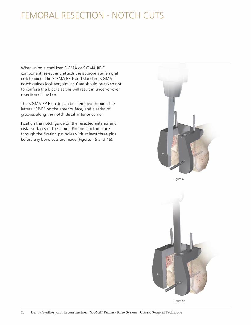
When using a stabilized SIGMA or SIGMA RP-F component, select and attach the appropriate femoral notch guide. The SIGMA RP-F and standard SIGMA notch guides look very similar. Care should be taken not to confuse the blocks as this will result in under-or-over resection of the box.
The SIGMA RP-F guide can be identified through the letters “RP-F” on the anterior face, and a series of grooves along the notch distal anterior corner.
Position the notch guide on the resected anterior and distal surfaces of the femur. Pin the block in place through the fixation pin holes with at least three pins before any bone cuts are made (Figures 45 and 46).
28 DePuy Synthes Joint Reconstruction SIGMA® Primary Knee System Classic Surgical Technique
TRIAL COMPONENTS (FOR FIXED BEARING, SEE APPENDIX A)
Figure 48
Figure 47
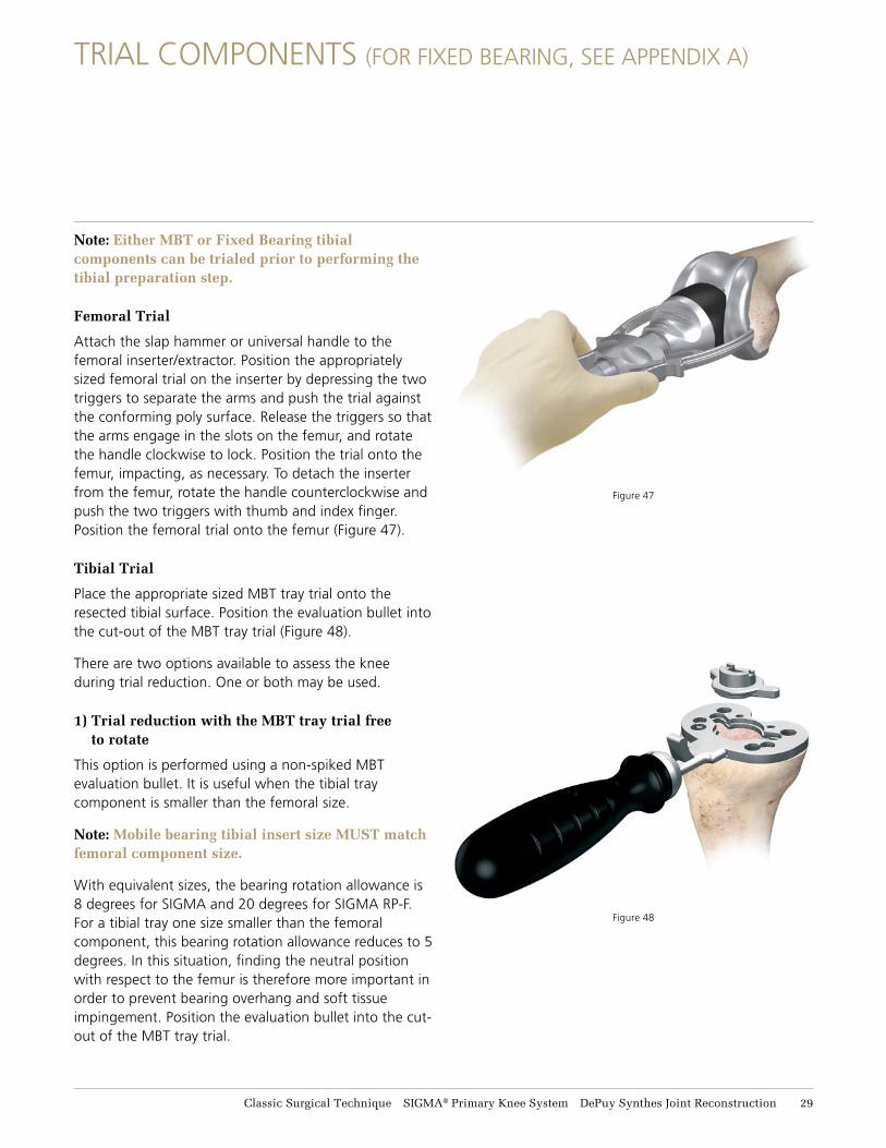
Note: Either MBT or Fixed Bearing tibial components can be trialed prior to performing the tibial preparation step.
Femoral Trial
Attach the slap hammer or universal handle to the femoral inserter/extractor. Position the appropriately sized femoral trial on the inserter by depressing the two triggers to separate the arms and push the trial against the conforming poly surface. Release the triggers so that the arms engage in the slots on the femur, and rotate the handle clockwise to lock. Position the trial onto the femur, impacting, as necessary. To detach the inserter from the femur, rotate the handle counterclockwise and push the two triggers with thumb and index finger. Position the femoral trial onto the femur (Figure 47).
Tibial Trial
Place the appropriate sized MBT tray trial onto the resected tibial surface. Position the evaluation bullet into the cut-out of the MBT tray trial (Figure 48).
There are two options available to assess the knee during trial reduction. One or both may be used.
1) Trial reduction with the MBT tray trial free to rotate
This option is performed using a non-spiked MBT evaluation bullet. It is useful when the tibial tray component is smaller than the femoral size.
Note: Mobile bearing tibial insert size MUST match femoral component size.
With equivalent sizes, the bearing rotation allowance is 8 degrees for SIGMA and 20 degrees for SIGMA RP-F. For a tibial tray one size smaller than the femoral component, this bearing rotation allowance reduces to 5 degrees. In this situation, finding the neutral position with respect to the femur is therefore more important in order to prevent bearing overhang and soft tissue impingement. Position the evaluation bullet into the cut-out of the MBT tray trial.
Classic Surgical Technique SIGMA® Primary Knee System DePuy Synthes Joint Reconstruction 29
TRIAL COMPONENTS (FOR FIXED BEARING, SEE APPENDIX A)
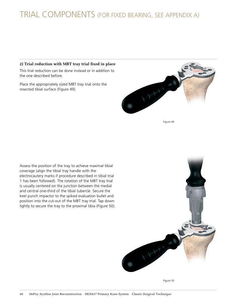
2) Trial reduction with MBT tray trial fixed in place
This trial reduction can be done instead or in addition to the one described before.
Place the appropriately sized MBT tray trial onto the resected tibial surface (Figure 49).
Assess the position of the tray to achieve maximal tibial coverage (align the tibial tray handle with the electrocautery marks if procedure described in tibial trial 1 has been followed). The rotation of the MBT tray trial is usually centered on the junction between the medial and central one-third of the tibial tubercle. Secure the keel punch impactor to the spiked evaluation bullet and position into the cut-out of the MBT tray trial. Tap down lightly to secure the tray to the proximal tibia (Figure 50).
Figure 50
Figure 49
31 DePuy Synthes Joint Reconstruction SIGMA® Primary Knee System Classic Surgical Technique
TRIAL COMPONENTS (FOR FIXED BEARING, SEE APPENDIX A)
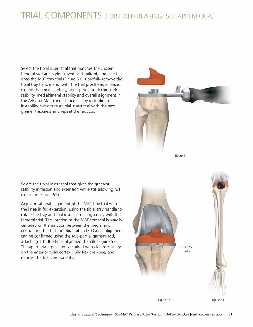
Select the tibial insert trial that matches the chosen femoral size and style, curved or stabilized, and insert it onto the MBT tray trial (Figure 51). Carefully remove the tibial tray handle and, with the trial prosthesis in place, extend the knee carefully, noting the anterior/posterior stability, medial/lateral stability and overall alignment in the A/P and M/L plane. If there is any indication of instability, substitute a tibial insert trial with the next greater thickness and repeat the reduction.
Select the tibial insert trial that gives the greatest stability in flexion and extension while still allowing full extension (Figure 52).
Adjust rotational alignment of the MBT tray trial with the knee in full extension, using the tibial tray handle to rotate the tray and trial insert into congruency with the femoral trial. The rotation of the MBT tray trial is usually centered on the junction between the medial and central one-third of the tibial tubercle. Overall alignment can be confirmed using the two-part alignment rod, attaching it to the tibial alignment handle (Figure 53). The appropriate position is marked with electro-cautery on the anterior tibial cortex. Fully flex the knee, and remove the trial components.
Figure 51
Cautery
marks
Figure 53Figure 52
Classic Surgical Technique SIGMA® Primary Knee System DePuy Synthes Joint Reconstruction 31
TIBIAL PREPARATION - MBT
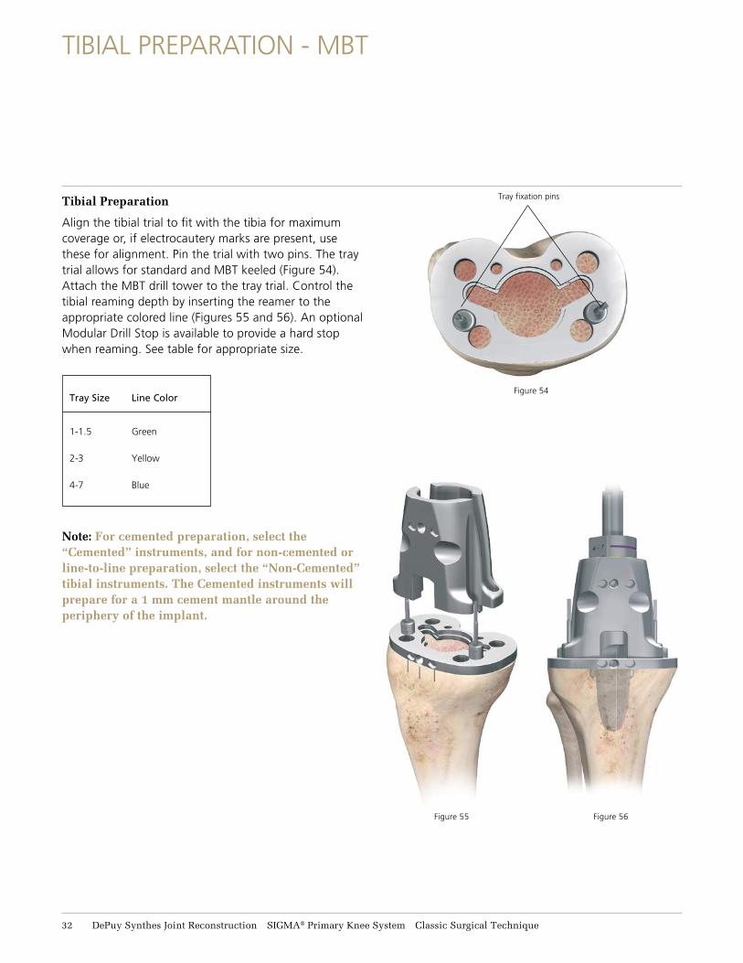
Tibial Preparation
Align the tibial trial to fit with the tibia for maximum coverage or, if electrocautery marks are present, use these for alignment. Pin the trial with two pins. The tray trial allows for standard and MBT keeled (Figure 54). Attach the MBT drill tower to the tray trial. Control the tibial reaming depth by inserting the reamer to the appropriate colored line (Figures 55 and 56). An optional Modular Drill Stop is available to provide a hard stop when reaming. See table for appropriate size.
Note: For cemented preparation, select the “Cemented” instruments, and for non-cemented or line-to-line preparation, select the “Non-Cemented” tibial instruments. The Cemented instruments will prepare for a 1 mm cement mantle around the periphery of the implant.
Tray Size Line Color
1-1.5 Green
2-3 Yellow
4-7 Blue
Figure 54
Figure 55 Figure 56
Tray fixation pins
32 DePuy Synthes Joint Reconstruction SIGMA® Primary Knee System Classic Surgical Technique
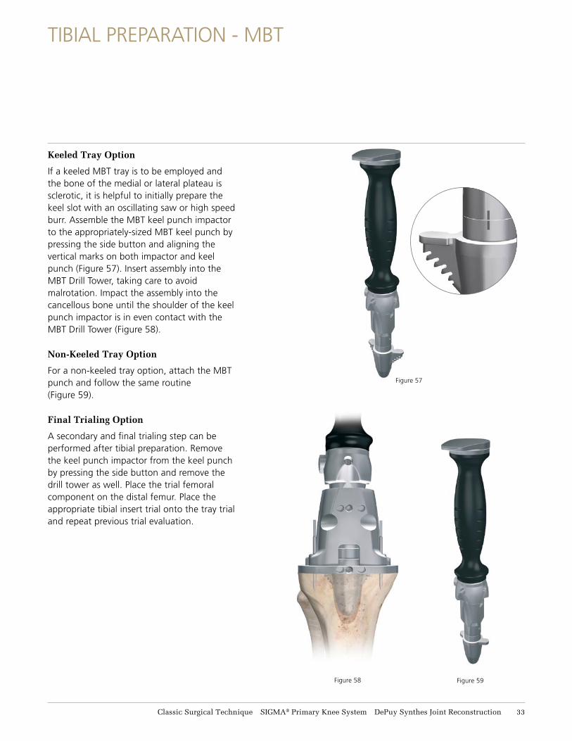
Keeled Tray Option
If a keeled MBT tray is to be employed and the bone of the medial or lateral plateau is sclerotic, it is helpful to initially prepare the keel slot with an oscillating saw or high speed burr. Assemble the MBT keel punch impactor to the appropriately-sized MBT keel punch by pressing the side button and aligning the vertical marks on both impactor and keel punch (Figure 57). Insert assembly into the MBT Drill Tower, taking care to avoid malrotation. Impact the assembly into the cancellous bone until the shoulder of the keel punch impactor is in even contact with the MBT Drill Tower (Figure 58).
Non-Keeled Tray Option
For a non-keeled tray option, attach the MBT punch and follow the same routine (Figure 59).
Final Trialing Option
A secondary and final trialing step can be performed after tibial preparation. Remove the keel punch impactor from the keel punch by pressing the side button and remove the drill tower as well. Place the trial femoral component on the distal femur. Place the appropriate tibial insert trial onto the tray trial and repeat previous trial evaluation.
TIBIAL PREPARATION - MBT
Figure 58 Figure 59
Figure 57
Classic Surgical Technique SIGMA® Primary Knee System DePuy Synthes Joint Reconstruction 33

FINAL PATELLA PREPARATION
Select a template that most adequately covers the resected surface without overhang (Figure 60). If used, remove the patella wafer from the patella. Position the template handle on the medial side of the everted patella. Firmly engage the template to the resected surface and drill the holes with the appropriate drill bit (Figure 61).
Cement the patellar implant. Thoroughly cleanse the cut surface with pulsatile lavage. Apply cement to the surface and insert the component. The patellar clamp is designed to fully seat and stabilize the implant as the cement polymerizes. Center the silicon O-ring over the articular surface of the implant and the metal backing plate against the anterior cortex, avoiding skin entrapment. When snug, close the handles and hold by the ratchet until polymerization is complete. Remove all extruded cement with a curette. Release the clamp by unlocking the locking switch and squeezing the handle together (Figure 62).
Reduce the patella and evaluate the patella implant. Unrestricted range of motion, free bearing movement and proper patellar tracking should be evident (Figure 63).
Figure 60 Figure 61
Locking switch
Figure 62
Figure 63
34 DePuy Synthes Joint Reconstruction SIGMA® Primary Knee System Classic Surgical Technique
CEMENTING TECHNIQUE
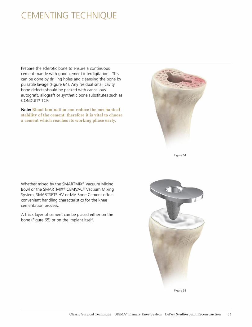
Prepare the sclerotic bone to ensure a continuous cement mantle with good cement interdigitation. This can be done by drilling holes and cleansing the bone by pulsatile lavage (Figure 64). Any residual small cavity bone defects should be packed with cancellous autograft, allograft or synthetic bone substitutes such as CONDUIT® TCP.
Note: Blood lamination can reduce the mechanical stability of the cement, therefore it is vital to choose a cement which reaches its working phase early.
Whether mixed by the SMARTMIX® Vacuum Mixing Bowl or the SMARTMIX® CEMVAC® Vacuum Mixing System, SMARTSET® HV or MV Bone Cement offers convenient handling characteristics for the knee cementation process.
A thick layer of cement can be placed either on the bone (Figure 65) or on the implant itself.
Figure 64
Figure 65
Classic Surgical Technique SIGMA® Primary Knee System DePuy Synthes Joint Reconstruction 35
FINAL COMPONENT IMPLANTATION
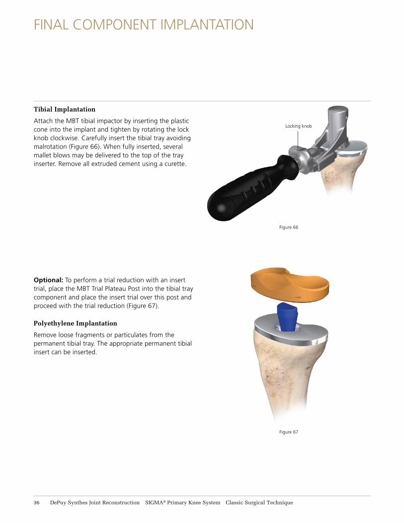
Tibial Implantation
Attach the MBT tibial impactor by inserting the plastic cone into the implant and tighten by rotating the lock knob clockwise. Carefully insert the tibial tray avoiding malrotation (Figure 66). When fully inserted, several mallet blows may be delivered to the top of the tray inserter. Remove all extruded cement using a curette.
Optional: To perform a trial reduction with an insert trial, place the MBT Trial Plateau Post into the tibial tray component and place the insert trial over this post and proceed with the trial reduction (Figure 67).
Polyethylene Implantation
Remove loose fragments or particulates from the permanent tibial tray. The appropriate permanent tibial insert can be inserted.
Locking knob
Figure 67
Figure 66
36 DePuy Synthes Joint Reconstruction SIGMA® Primary Knee System Classic Surgical Technique
FINAL COMPONENT IMPLANTATION
Figure 68
Figure 69
Classic Surgical Technique SIGMA® Primary Knee System DePuy Synthes Joint Reconstruction 37
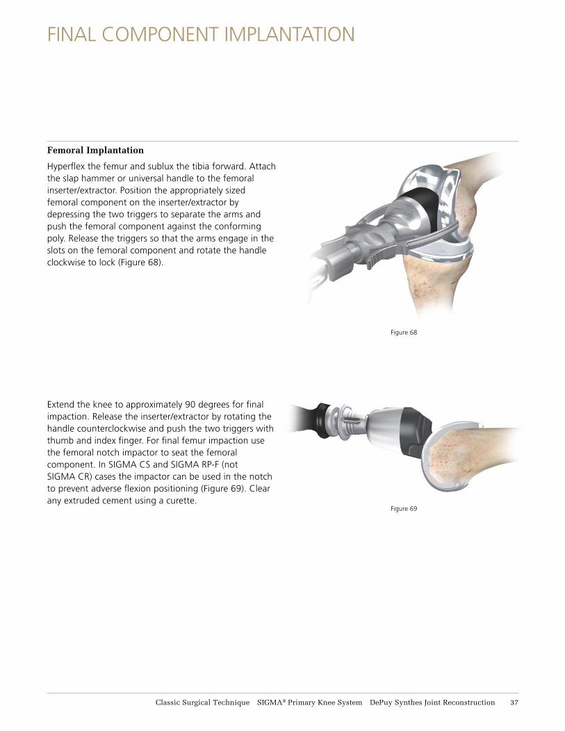
Femoral Implantation
Hyperflex the femur and sublux the tibia forward. Attach the slap hammer or universal handle to the femoral inserter/extractor. Position the appropriately sized femoral component on the inserter/extractor by depressing the two triggers to separate the arms and push the femoral component against the conforming poly. Release the triggers so that the arms engage in the slots on the femoral component and rotate the handle clockwise to lock (Figure 68).
Extend the knee to approximately 90 degrees for final impaction. Release the inserter/extractor by rotating the handle counterclockwise and push the two triggers with thumb and index finger. For final femur impaction use the femoral notch impactor to seat the femoral component. In SIGMA CS and SIGMA RP-F (not SIGMA CR) cases the impactor can be used in the notch to prevent adverse flexion positioning (Figure 69). Clear any extruded cement using a curette.
CLOSURE
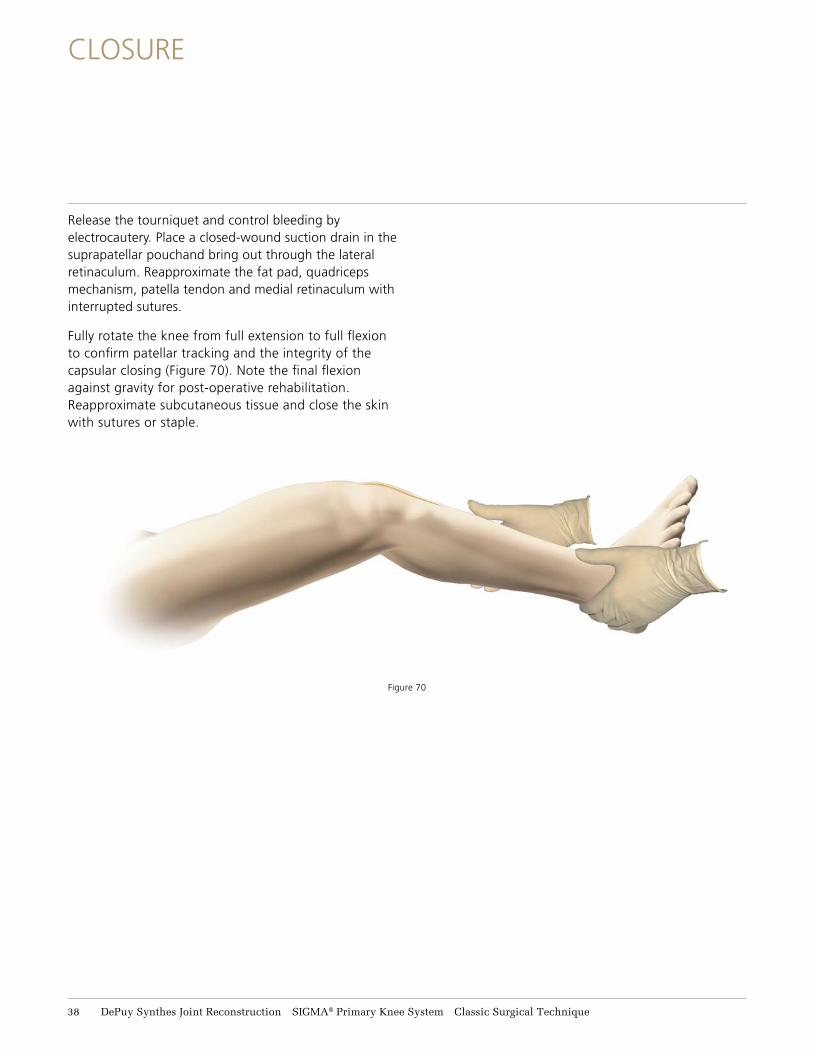
Release the tourniquet and control bleeding by electrocautery. Place a closed-wound suction drain in the suprapatellar pouchand bring out through the lateral retinaculum. Reapproximate the fat pad, quadriceps mechanism, patella tendon and medial retinaculum with interrupted sutures.
Fully rotate the knee from full extension to full flexion to confirm patellar tracking and the integrity of the capsular closing (Figure 70). Note the final flexion against gravity for post-operative rehabilitation. Reapproximate subcutaneous tissue and close the skin with sutures or staple.
Figure 70
38 DePuy Synthes Joint Reconstruction SIGMA® Primary Knee System Classic Surgical Technique
APPENDIX A: FIXED BEARING MODULAR TIBIAL PREPARATION
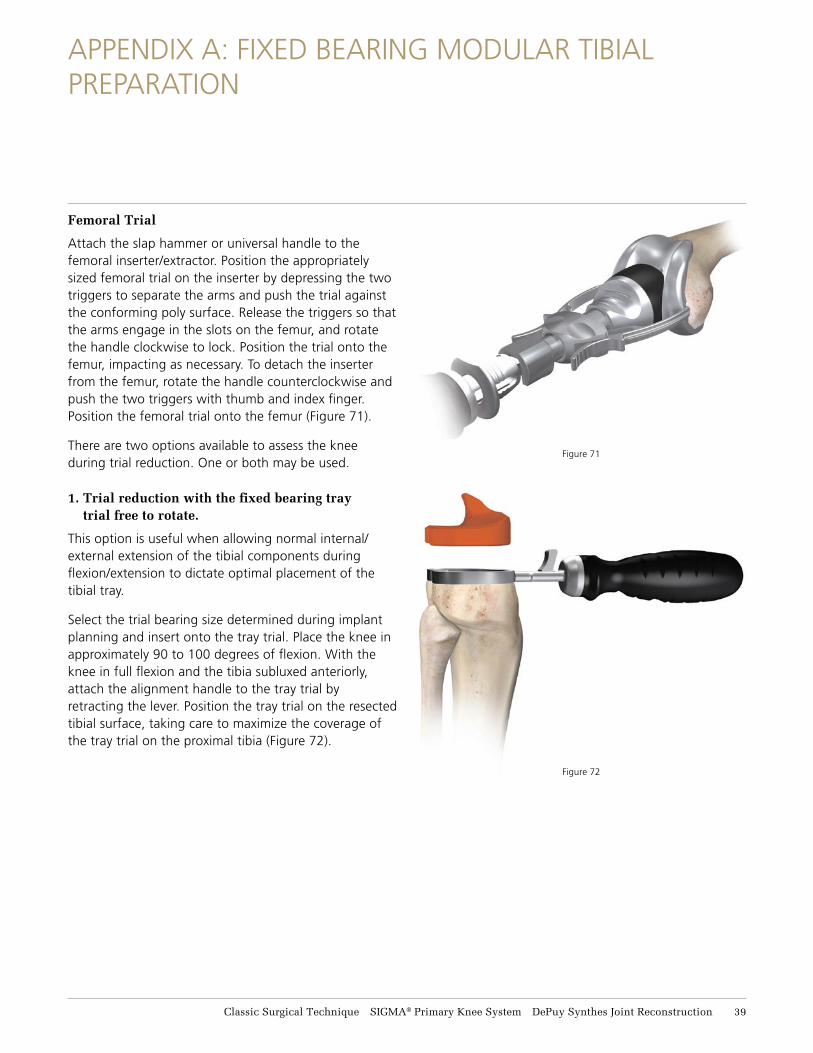
Femoral Trial
Attach the slap hammer or universal handle to the femoral inserter/extractor. Position the appropriately sized femoral trial on the inserter by depressing the two triggers to separate the arms and push the trial against the conforming poly surface. Release the triggers so that the arms engage in the slots on the femur, and rotate the handle clockwise to lock. Position the trial onto the femur, impacting as necessary. To detach the inserter from the femur, rotate the handle counterclockwise and push the two triggers with thumb and index finger. Position the femoral trial onto the femur (Figure 71).
There are two options available to assess the knee during trial reduction. One or both may be used.
1. Trial reduction with the fixed bearing tray trial free to rotate.
This option is useful when allowing normal internal/ external extension of the tibial components during flexion/extension to dictate optimal placement of the tibial tray.
Select the trial bearing size determined during implant planning and insert onto the tray trial. Place the knee in approximately 90 to 100 degrees of flexion. With the knee in full flexion and the tibia subluxed anteriorly, attach the alignment handle to the tray trial by retracting the lever. Position the tray trial on the resected tibial surface, taking care to maximize the coverage of the tray trial on the proximal tibia (Figure 72).
Figure 71
Figure 72
Classic Surgical Technique SIGMA® Primary Knee System DePuy Synthes Joint Reconstruction 39
APPENDIX A: FIXED BEARING MODULAR TIBIAL PREPARATION
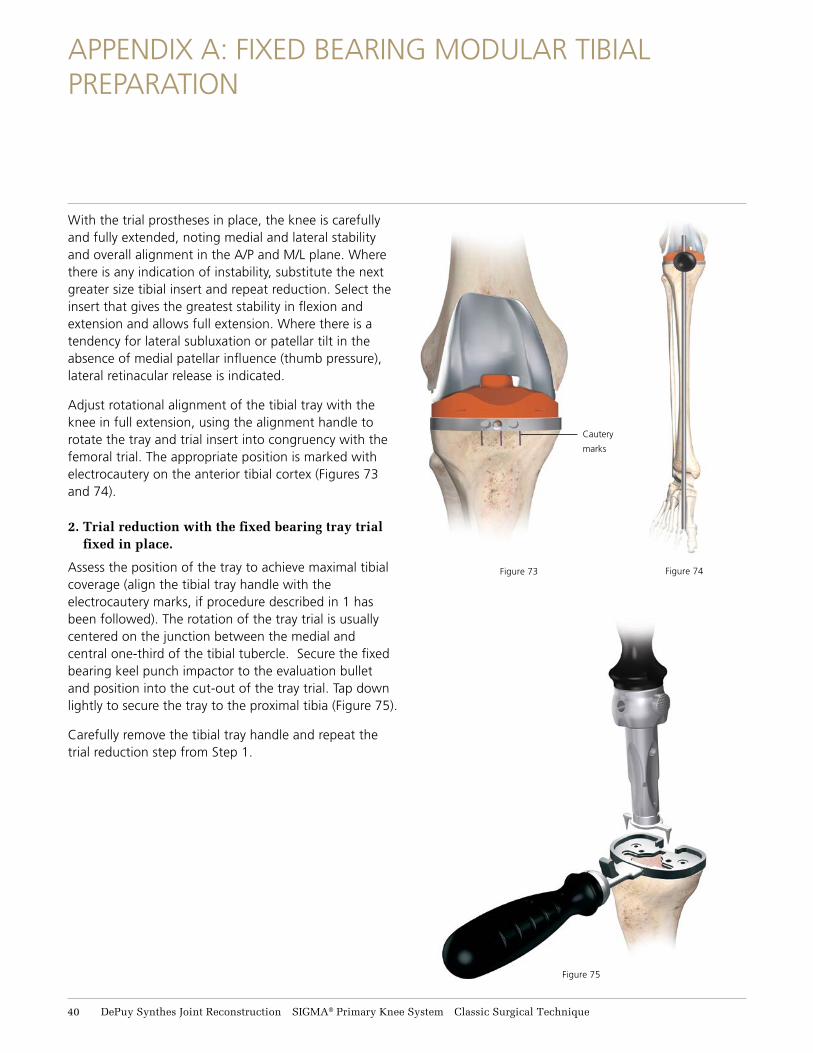
With the trial prostheses in place, the knee is carefully and fully extended, noting medial and lateral stability and overall alignment in the A/P and M/L plane. Where there is any indication of instability, substitute the next greater size tibial insert and repeat reduction. Select the insert that gives the greatest stability in flexion and extension and allows full extension. Where there is a tendency for lateral subluxation or patellar tilt in the absence of medial patellar influence (thumb pressure), lateral retinacular release is indicated.
Adjust rotational alignment of the tibial tray with the knee in full extension, using the alignment handle to rotate the tray and trial insert into congruency with the femoral trial. The appropriate position is marked with electrocautery on the anterior tibial cortex (Figures 73 and 74).
2. Trial reduction with the fixed bearing tray trial fixed in place.
Assess the position of the tray to achieve maximal tibial coverage (align the tibial tray handle with the electrocautery marks, if procedure described in 1 has been followed). The rotation of the tray trial is usually centered on the junction between the medial and central one-third of the tibial tubercle. Secure the fixed bearing keel punch impactor to the evaluation bullet and position into the cut-out of the tray trial. Tap down lightly to secure the tray to the proximal tibia (Figure 75).
Carefully remove the tibial tray handle and repeat the trial reduction step from Step 1.
Cautery
marks
Figure 75
Figure 73 Figure 74
41 DePuy Synthes Joint Reconstruction SIGMA® Primary Knee System Classic Surgical Technique
APPENDIX A: FIXED BEARING MODULAR TIBIAL PREPARATION
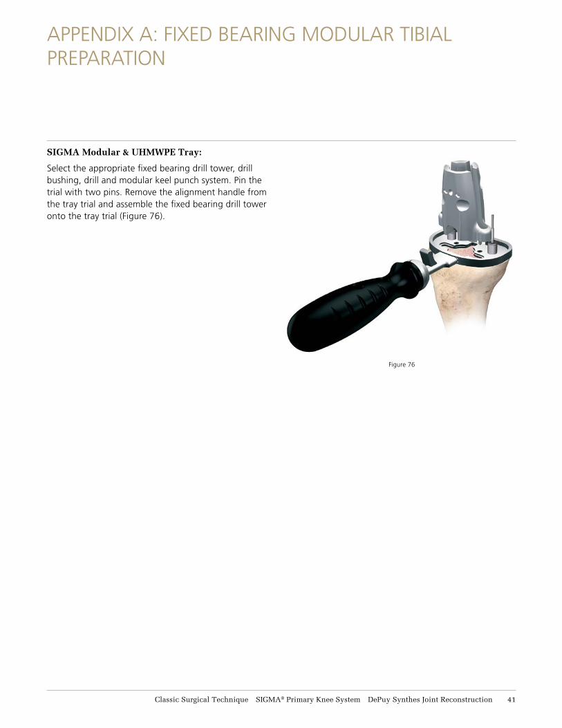
SIGMA Modular & UHMWPE Tray:
Select the appropriate fixed bearing drill tower, drill bushing, drill and modular keel punch system. Pin the trial with two pins. Remove the alignment handle from the tray trial and assemble the fixed bearing drill tower onto the tray trial (Figure 76).
Figure 76
Classic Surgical Technique SIGMA® Primary Knee System DePuy Synthes Joint Reconstruction 41
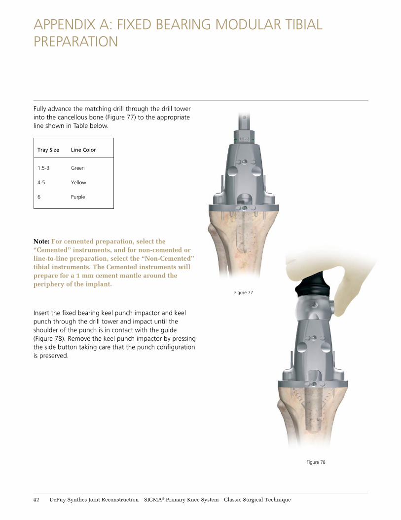
Figure 78
APPENDIX A: FIXED BEARING MODULAR TIBIAL PREPARATION
Figure 77
Fully advance the matching drill through the drill tower into the cancellous bone (Figure 77) to the appropriate line shown in Table below.
Note: For cemented preparation, select the “Cemented” instruments, and for non-cemented or line-to-line preparation, select the “Non-Cemented” tibial instruments. The Cemented instruments will prepare for a 1 mm cement mantle around the periphery of the implant.
Insert the fixed bearing keel punch impactor and keel punch through the drill tower and impact until the shoulder of the punch is in contact with the guide (Figure 78). Remove the keel punch impactor by pressing the side button taking care that the punch configuration is preserved.
Tray Size Line Color
1.5-3 Green
4-5 Yellow
6 Purple
42 DePuy Synthes Joint Reconstruction SIGMA® Primary Knee System Classic Surgical Technique
APPENDIX A: FIXED BEARING STANDARD TIBIAL PREPARATION
SIGMA Cruciform Keel Tray:
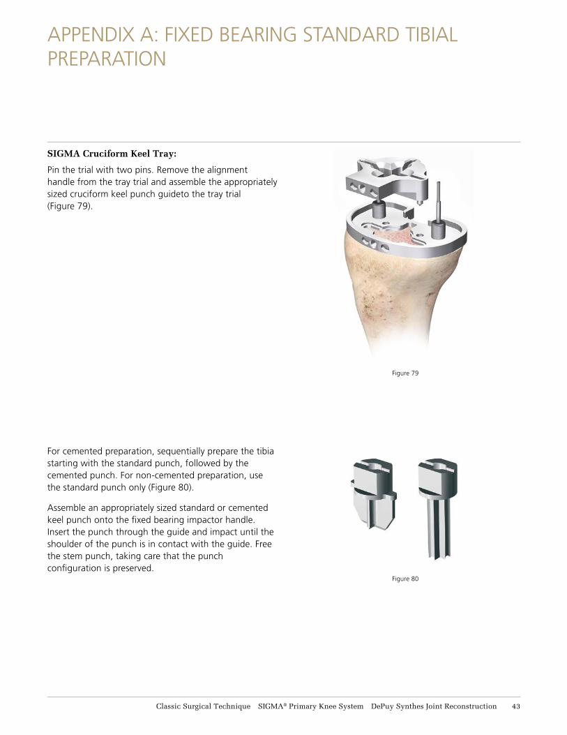
Pin the trial with two pins. Remove the alignment handle from the tray trial and assemble the appropriately sized cruciform keel punch guideto the tray trial (Figure 79).
For cemented preparation, sequentially prepare the tibia starting with the standard punch, followed by the cemented punch. For non-cemented preparation, use the standard punch only (Figure 80).
Assemble an appropriately sized standard or cemented keel punch onto the fixed bearing impactor handle. Insert the punch through the guide and impact until the shoulder of the punch is in contact with the guide. Free the stem punch, taking care that the punch configuration is preserved.
Figure 79
Figure 80
Classic Surgical Technique SIGMA® Primary Knee System DePuy Synthes Joint Reconstruction 43
APPENDIX B: TIBIAL I.M. JIG ALIGNMENT
Figure 81
Figure 82
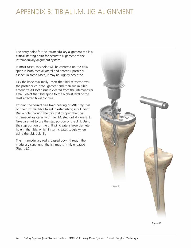
The entry point for the intramedullary alignment rod is a critical starting point for accurate alignment of the intramedullary alignment system.
In most cases, this point will be centered on the tibial spine in both medial/lateral and anterior/ posterior aspect. In some cases, it may be slightly eccentric.
Flex the knee maximally, insert the tibial retractor over the posterior cruciate ligament and then sublux tibia anteriorly. All soft tissue is cleared from the intercondylar area. Resect the tibial spine to the highest level of the least affected tibial condyle.
Position the correct size fixed bearing or MBT tray trial on the proximal tibia to aid in establishing a drill point. Drill a hole through the tray trial to open the tibia intramedullary canal with the I.M. step drill (Figure 81). Take care not to use the step portion of the drill. Using the step portion of the drill will create a large diameter hole in the tibia, which in turn creates toggle when using the I.M. tibial jig.
The intramedullary rod is passed down through the medullary canal until the isthmus is firmly engaged (Figure 82).
44 DePuy Synthes Joint Reconstruction SIGMA® Primary Knee System Classic Surgical Technique
APPENDIX B: TIBIAL I.M. JIG ALIGNMENT
Remove the handle and place the I.M. rotation guide over the I.M. rod to define the correct rotational tibia axis, referring to the condylar axis, medial 1/3 of the tibia tubercle and the center of the ankle (Figure 83).
The angle can also be checked relative to the posterior condylar axis by moving the slider forward and rotating it until it is aligned with the posterior condyles. The marks on the rotation guide are in 2 degree increments and give an indication of the angle between the posterior condylar axis and the chosen rotation.
The rotation can then be marked through the slot on the rotation guide. The rotation guide can then be removed. After the correct rotation has been marked, slide the I.M. tibial jig over the I.M. rod and rotate the I.M. jig until the rotation line on the jig lines up with the line previously marked using the rotation guide.
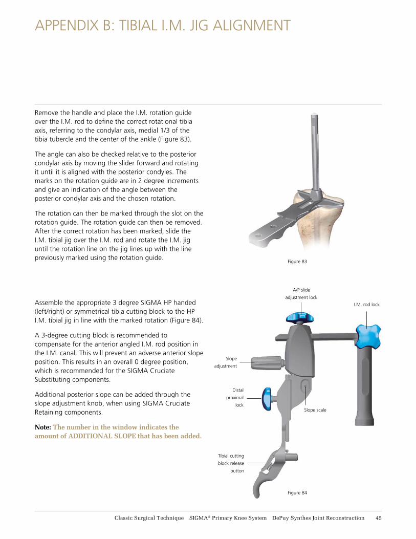
Assemble the appropriate 3 degree SIGMA HP handed (left/right) or symmetrical tibia cutting block to the HP I.M. tibial jig in line with the marked rotation (Figure 84).
A 3-degree cutting block is recommended to compensate for the anterior angled I.M. rod position in the I.M. canal. This will prevent an adverse anterior slope position. This results in an overall 0 degree position, which is recommended for the SIGMA Cruciate Substituting components.
Additional posterior slope can be added through the slope adjustment knob, when using SIGMA Cruciate Retaining components.
Note: The number in the window indicates the amount of ADDITIONAL SLOPE that has been added.
Figure 83
Figure 84
Tibial cutting
block release
button
I.M. rod lock
A/P slide
adjustment lock
Distal
proximal
lock
Slope
adjustment
Slope scale
Classic Surgical Technique SIGMA® Primary Knee System DePuy Synthes Joint Reconstruction 45
APPENDIX B: TIBIAL I.M. JIG ALIGNMENT
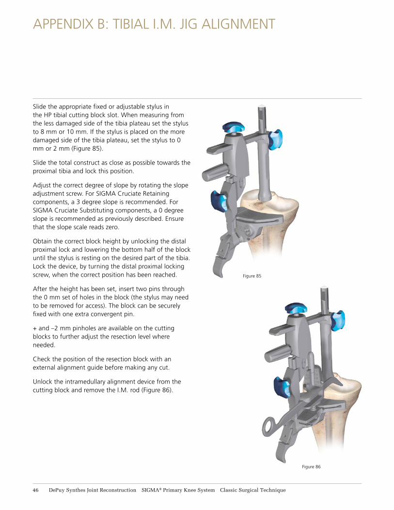
Slide the appropriate fixed or adjustable stylus in the HP tibial cutting block slot. When measuring from the less damaged side of the tibia plateau set the stylus to 8 mm or 10 mm. If the stylus is placed on the more damaged side of the tibia plateau, set the stylus to 0 mm or 2 mm (Figure 85).
Slide the total construct as close as possible towards the proximal tibia and lock this position.
Adjust the correct degree of slope by rotating the slope adjustment screw. For SIGMA Cruciate Retaining components, a 3 degree slope is recommended. For SIGMA Cruciate Substituting components, a 0 degree slope is recommended as previously described. Ensure that the slope scale reads zero.
Obtain the correct block height by unlocking the distal proximal lock and lowering the bottom half of the block until the stylus is resting on the desired part of the tibia. Lock the device, by turning the distal proximal locking screw, when the correct position has been reached.
After the height has been set, insert two pins through the 0 mm set of holes in the block (the stylus may need to be removed for access). The block can be securely fixed with one extra convergent pin.
+ and –2 mm pinholes are available on the cutting blocks to further adjust the resection level where needed.
Check the position of the resection block with an external alignment guide before making any cut.
Unlock the intramedullary alignment device from the cutting block and remove the I.M. rod (Figure 86).
Figure 85
Figure 86
46 DePuy Synthes Joint Reconstruction SIGMA® Primary Knee System Classic Surgical Technique
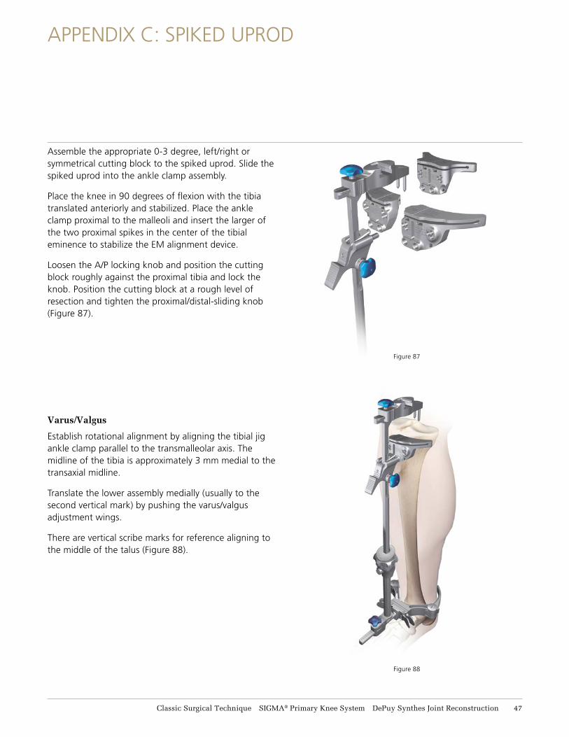
Figure 88
Assemble the appropriate 0-3 degree, left/right or symmetrical cutting block to the spiked uprod. Slide the spiked uprod into the ankle clamp assembly.
Place the knee in 90 degrees of flexion with the tibia translated anteriorly and stabilized. Place the ankle clamp proximal to the malleoli and insert the larger of the two proximal spikes in the center of the tibial eminence to stabilize the EM alignment device.
Loosen the A/P locking knob and position the cutting block roughly against the proximal tibia and lock the knob. Position the cutting block at a rough level of resection and tighten the proximal/distal-sliding knob (Figure 87).
Varus/Valgus
Establish rotational alignment by aligning the tibial jig ankle clamp parallel to the transmalleolar axis. The midline of the tibia is approximately 3 mm medial to the transaxial midline.
Translate the lower assembly medially (usually to the second vertical mark) by pushing the varus/valgus adjustment wings.
There are vertical scribe marks for reference aligning to the middle of the talus (Figure 88).
APPENDIX C: SPIKED UPROD
Figure 87
Classic Surgical Technique SIGMA® Primary Knee System DePuy Synthes Joint Reconstruction 47
APPENDIX C: SPIKED UPROD
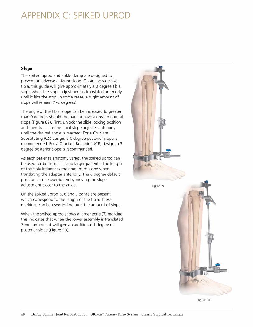
Slope
The spiked uprod and ankle clamp are designed to prevent an adverse anterior slope. On an average size tibia, this guide will give approximately a 0 degree tibial slope when the slope adjustment is translated anteriorly until it hits the stop. In some cases, a slight amount of slope will remain (1-2 degrees).
The angle of the tibial slope can be increased to greater than 0 degrees should the patient have a greater natural slope (Figure 89). First, unlock the slide locking position and then translate the tibial slope adjuster anteriorly until the desired angle is reached. For a Cruciate Substituting (CS) design, a 0 degree posterior slope is recommended. For a Cruciate Retaining (CR) design, a 3 degree posterior slope is recommended.
As each patient’s anatomy varies, the spiked uprod can be used for both smaller and larger patients. The length of the tibia influences the amount of slope when translating the adapter anteriorly. The 0 degree default position can be overridden by moving the slope adjustment closer to the ankle.
On the spiked uprod 5, 6 and 7 zones are present, which correspond to the length of the tibia. These markings can be used to fine tune the amount of slope.
When the spiked uprod shows a larger zone (7) marking, this indicates that when the lower assembly is translated 7 mm anterior, it will give an additional 1 degree of posterior slope (Figure 90).
Figure 89
Figure 90
48 DePuy Synthes Joint Reconstruction SIGMA® Primary Knee System Classic Surgical Technique

APPENDIX C: SPIKED UPROD
Height
Loosen the proximal/distal sliding knob, insert the adjustable tibial stylus into the cutting block, and adjust to the correct level of resection.
When measuring from the less damaged side of the tibial plateau, set the stylus to 8 mm or 10 mm. If the stylus is placed on the more damaged side of the tibial plateau, set the stylus to 0 mm or 2 mm.
Adjustment of resection height on the stylus should be done outside the joint space before locating the stylus in the cutting block.
If planning to resect through the slot, position the foot of the tibial stylus marked “slotted” into the slot of the tibial cutting block (Figure 91). If planning to resect on top of the cutting block, place the foot marked “non-slotted” into the cutting slot.
Drop the block and stylus assembly so that the stylus touches the desired point on the tibia. Care should be taken with severe valgus deformity, not to over resect the tibia.
Tibial Resection
After the height has been set, lock the proximal/ distal sliding knob and pin the block through the 0 mm set of holes (the stylus may need to be removed for access). +/-2 mm pinholes are available on the resection blocks to further adjust the resection level where needed.
The block can be securely fixed with one extra convergent pin.
Spiked Uprod Removal
Loosen the A/P locking knob. Press the cutting block release button and translate the spiked uprod anterior to disengage from the cutting block.
Connect the slap hammer to the top of the spiked uprod and disengage the spikes from the proximal tibia. Remove the tibial jig and perform the appropriate resection (Figure 92).
Figure 92
Press Release trigger to disengage the tibial
cutting block
After disengaging from the tibial block, use the slap hammer to disengage the spikes from the proximal tibia
Figure 91
Classic Surgical Technique SIGMA® Primary Knee System DePuy Synthes Joint Reconstruction 49

ORDERING INFORMATION
Tibia Resection 9505-01-228 HP EM Tibial Jig Uprod
9505-01-229 HP EM Tibial Jig Ankle Clamp
9505-01-202 HP I.M. Tibia Rotation Guide
9505-01-203 HP I.M. Tibia Jig
9505-01-204 SIGMA HP 0 degree Symmetrical Cut Block
9505-01-222 SIGMA HP 0 degree Left Cut Block
9505-01-223 SIGMA HP 0 degree Right Cut Block
9505-01-205 SIGMA HP 3 degree Symmetrical Cut Block
9505-01-224 SIGMA HP 3 degree Left Cut Block
9505-01-225 SIGMA HP 3 degree Right Cut Block
9505-01-209 SIGMA HP Adj Tibial Stylus
9505-01-230 HP EM Tibial Jig Spiked Uprod
9505-01-164 SIGMA HP Slot Stylus 0/2 mm
9505-01-167 SIGMA HP Nonslotted Stylus 0/2 mm
9505-01-211 SIGMA HP Slotted Stylus 8/10 mm
9505-01-213 SIGMA HP Nonslotted Stylus 8/10 mm
Femoral Resection99-2011 I.M. Rod Handle
96-6121 I.M. Rod 300 mm
9505-02-079 HP Step I.M. Reamer
9505-01-234 SIGMA HP Distal Femoral Align Guide
9505-01-235 SIGMA HP Distal Femoral Resection Guide
9505-01-238 SIGMA HP Distal Femoral Connector
9505-01-236 SIGMA HP Distal Femoral Block
9505-01-307 HP Alignment Tower
9505-01-207 HP Alignment Rod
96-6530 Reference Guide
96-6120 SP2 I.M. Rod 400 mm
9505-01-239 SIGMA HP Revision Distal Femoral Cutting Block
Measured Classic Femoral Sizing & Rotation9505-01-272 HP Classic Anterior Down Femoral Sizer
9505-01-277 HP Classic Posterior Up Femoral Sizer
9505-01-273 HP Classic Rotation Guide 0 degree
9505-01-274 HP Classic Rotation Guide 3 degree
9505-01-275 HP Classic Rotation Guide 5 degree
9505-01-276 HP Classic Rotation Guide 7 degree
9505-01-301 HP Anterior Down Converter
9505-01-302 HP Posterior Up Converter
Femoral Resection9505-01-025 SIGMA HP Classic A/P Block Size 1.5
9505-01-026 SIGMA HP Classic A/P Block Size 2
9505-01-027 SIGMA HP Classic A/P Block Size 2.5
9505-01-028 SIGMA HP Classic A/P Block Size 3
9505-01-029 SIGMA HP Classic A/P Block Size 4
9505-01-030 SIGMA HP Classic A/P Block Size 5
9505-01-031 SIGMA HP Classic A/P Block Size 6
9505-01-032 Classic Femoral Chamfer Cut Block Handles
9505-01-000 SIGMA HP Femoral Notch Guide Size 1.5
9505-01-001 SIGMA HP Femoral Notch Guide Size 2
9505-01-002 SIGMA HP Femoral Notch Guide Size 2.5
9505-01-003 SIGMA HP Femoral Notch Guide Size 3
9505-01-004 SIGMA HP Femoral Notch Guide Size 4
9505-01-005 SIGMA HP Femoral Notch Guide Size 5
9505-01-006 SIGMA HP Femoral Notch Guide Size 6
9505-02-175 RP-F HP Classic A/P Block Size 1
9505-02-176 RP-F HP Classic A/P Block Size 1.5
9505-02-177 RP-F HP Classic A/P Block Size 2
9505-02-178 RP-F HP Classic A/P Block Size 2.5
9505-02-179 RP-F HP Classic A/P Block Size 3
9505-02-180 RP-F HP Classic A/P Block Size 4
9505-02-181 RP-F HP Classic A/P Block Size 5
9505-02-182 RP-F HP Classic A/P Block Size 6
9505-02-167 RP-F HP Femoral Notch Guide Size 1
9505-02-168 RP-F HP Femoral Notch Guide Size 1.5
9505-02-169 RP-F HP Femoral Notch Guide Size 2
9505-02-170 RP-F HP Femoral Notch Guide Size 2.5
9505-02-171 RP-F HP Femoral Notch Guide Size 3
9505-02-172 RP-F HP Femoral Notch Guide Size 4
9505-02-173 RP-F HP Femoral Notch Guide Size 5
9505-02-174 RP-F HP Femoral Notch Guide Size 6
Fixed Bearing Preparation 9505-02-040 SIGMA HP F.B.T. Tray Trial Size 1.5
9505-02-041 SIGMA HP F.B.T. Tray Trial Size 2
9505-02-042 SIGMA HP F.B.T. Tray Trial Size 2.5
9505-02-043 SIGMA HP F.B.T. Tray Trial Size 3
9505-02-044 SIGMA HP F.B.T. Tray Trial Size 4
9505-02-045 SIGMA HP F.B.T. Tray Trial Size 5
9505-02-046 SIGMA HP F.B.T. Tray Trial Size 6
51 DePuy Synthes Joint Reconstruction SIGMA® Primary Knee System Classic Surgical Technique
ORDERING INFORMATION
Fixed Bearing Preparation 9505-02-053 SIGMA HP F.B.T. Evaluation Bullet 1.5-3
9505-02-054 SIGMA HP F.B.T. Evaluation Bullet 4-6
9505-02-055 SIGMA HP F.B.T. Keel Punch Impact
9505-02-060 SIGMA HP F.B.T. Drill Tower
2178-30-123 MBT Tray Fixation Pins
9505-02-028 HP Tibial Tray Handle
9505-02-068 F.B.T. Modular Drill Stop
Fixed Bearing Modular Tray Preparation 9505-02-047 HP F.B.T. Cemented Keel Punch Size 1.5-3
9505-02-048 HP F.B.T. Cemented Keel Punch Size 4-5
9505-02-049 HP F.B.T. Cemented Keel Punch Size 6
9505-02-056 SIGMA HP F.B.T. Cemented Drill Size 1.5-3
9505-02-057 SIGMA HP F.B.T. Cemented Drill Size 4-6
9505-02-050 HP F.B.T. Non-Cemented Kl Punch Size 1.5-3
9505-02-051 HP F.B.T. Non-Cemented Kl Punch Size 4-5
9505-02-058 HP F.B.T. Non-Cemented Drill Size 1.5-3
9505-02-059 HP F.B.T. Non-Cemented Drill Size 4-6
9505-02-052 HP F.B.T. Non-Cemented Kl Punch Size 6
Fixed Bearing Standard Tray Preparation 9505-02-061 HP F.B.T. Standard Tibial Punch Guide Size 1.5-4
9505-02-062 HP F.B.T. Standard Tibial Punch Guide Size 5-6
9505-02-063 HP F.B.T. Standard Tibial Punch Size 1.5-2
9505-02-064 HP F.B.T. Standard Tibial Punch Size 2.5-4
9505-02-065 HP F.B.T. Standard Tibial Punch Size 5-6
9505-02-066 HP F.B.T. Standard Cm Tibial Punch Size 1.5-2
9505-02-067 HP F.B.T. Standard Cm Tibial Punch Size 2.5-6
MBT Preparation9505-02-000 HP MBT Tray Trial Size 1
9505-02-001 HP MBT Tray Trial Size 1.5
9505-02-002 HP MBT Tray Trial Size 2
9505-02-003 HP MBT Tray Trial Size 2.5
9505-02-004 HP MBT Tray Trial Size 3
9505-02-006 HP MBT Tray Trial Size 4
9505-02-007 HP MBT Tray Trial Size 5
9505-02-008 HP MBT Tray Trial Size 6
9505-02-009 HP MBT Tray Trial Size 7
9505-02-022 HP MBT Spiked Evaluation Bullet Size 1-3
MBT Preparation9505-02-023 HP MBT Spiked Evaluation Bullet Size 4-7
9505-02-099 MBT Evaluation Bullet Size 1-3”
9505-02-098 MBT Evaluation Bullet Size 4-7”
9505-02-027 HP MBT Drill Tower
9505-02-024 HP MBT Keel Punch Impact
2178-30-123 MBT Tray Fixation Pins
9505-02-028 HP Tibial Tray Handle
9505-02-029 MBT Modular Drill Stop
9505-02-038 MBT Central Stem Punch
2178-30-137 MBT RP Trial Button
2178-30-121 MBT RP Plateau Trial Post
MBT Keeled Preparation 9505-02-025 HP MBT Cemented Central Drill
9505-02-010 HP MBT Cemented Keel Punch Size 1-1.5
9505-02-011 HP MBT Cemented Keel Punch Size 2-3
9505-02-012 HP MBT Cemented Keel Punch Size 4-7
9505-02-026 HP MBT Non Cemented Central Drill
9505-02-013 HP MBT Non-Cemented Kl Punch Size 1-1.5
9505-02-014 HP MBT Non-Cemented Kl Punch Size 2-3
9505-02-015 HP MBT Non-Cemented Kl Punch Size 4-7
MBT Non Keeled Preparation 9505-02-025 HP MBT Cemented Central Drill
9505-02-016 HP MBT Cemented Punch Size 1-1.5
9505-02-017 HP MBT Cemented Punch Size 2-3
9505-02-018 HP MBT Cemented Punch Size 4-7
9505-02-026 HP MBT Non-Cemented Central Drill
9505-02-019 HP MBT Non-Cemented Punch Size 1-1.5
9505-02-020 HP MBT Non-Cemented Punch Size 2-3
9505-02-021 HP MBT Non-Cemented Punch Size 4-7
Femoral Trials 96-1007 SIGMA Femur CR Femur Trial Size 1.5 Left
96-1002 SIGMA Femur CR Femur Trial Size 2 Left
96-1008 SIGMA Femur CR Femur Trial Size 2.5 Left
96-1003 SIGMA Femur CR Femur Trial Size 3 Left
96-1004 SIGMA Femur CR Femur Trial Size 4 Left
96-1005 SIGMA Femur CR Femur Trial Size 5 Left
96-1006 SIGMA Femur CR Femur Trial Size 6 Left
Classic Surgical Technique SIGMA® Primary Knee System DePuy Synthes Joint Reconstruction 51
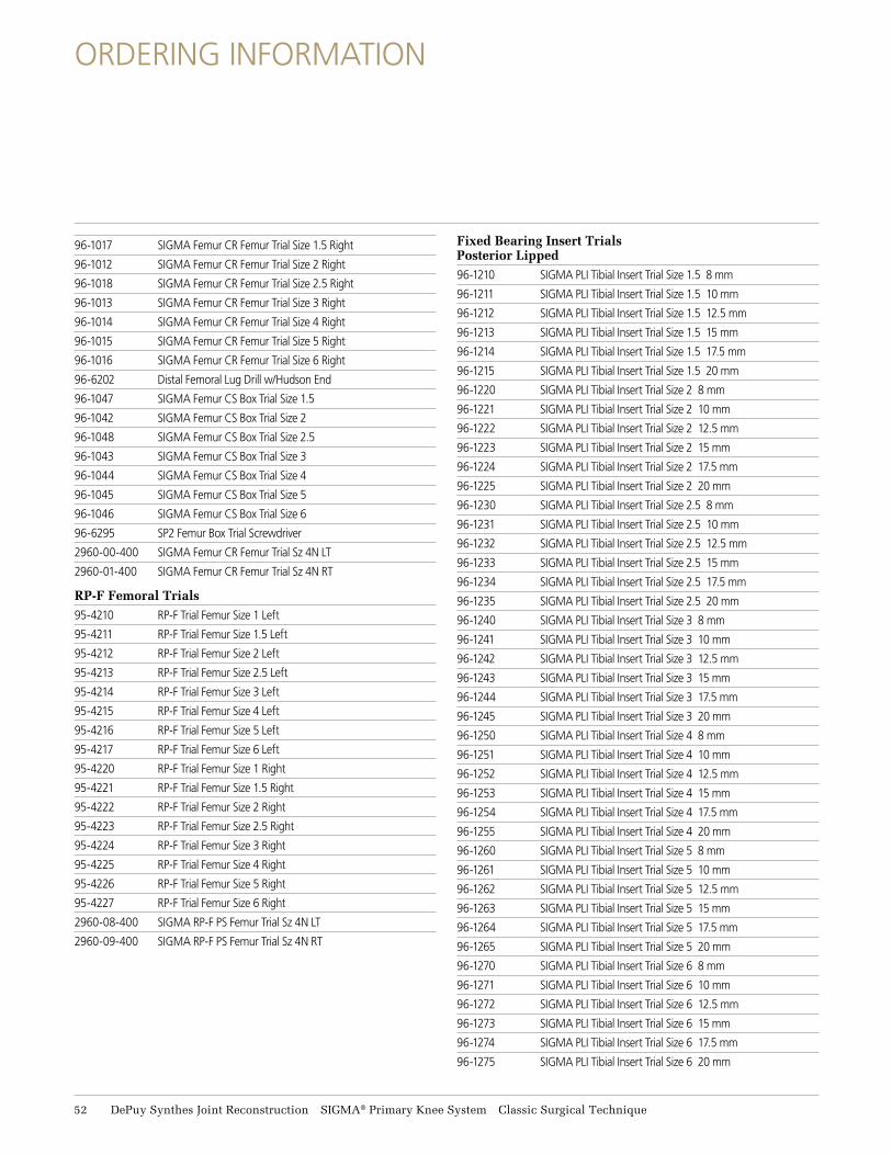
96-1017 SIGMA Femur CR Femur Trial Size 1.5 Right
96-1012 SIGMA Femur CR Femur Trial Size 2 Right
96-1018 SIGMA Femur CR Femur Trial Size 2.5 Right
96-1013 SIGMA Femur CR Femur Trial Size 3 Right
96-1014 SIGMA Femur CR Femur Trial Size 4 Right
96-1015 SIGMA Femur CR Femur Trial Size 5 Right
96-1016 SIGMA Femur CR Femur Trial Size 6 Right
96-6202 Distal Femoral Lug Drill w/Hudson End
96-1047 SIGMA Femur CS Box Trial Size 1.5
96-1042 SIGMA Femur CS Box Trial Size 2
96-1048 SIGMA Femur CS Box Trial Size 2.5
96-1043 SIGMA Femur CS Box Trial Size 3
96-1044 SIGMA Femur CS Box Trial Size 4
96-1045 SIGMA Femur CS Box Trial Size 5
96-1046 SIGMA Femur CS Box Trial Size 6
96-6295 SP2 Femur Box Trial Screwdriver
2960-00-400 SIGMA Femur CR Femur Trial Sz 4N LT
2960-01-400 SIGMA Femur CR Femur Trial Sz 4N RT
RP-F Femoral Trials 95-4210 RP-F Trial Femur Size 1 Left
95-4211 RP-F Trial Femur Size 1.5 Left
95-4212 RP-F Trial Femur Size 2 Left
95-4213 RP-F Trial Femur Size 2.5 Left
95-4214 RP-F Trial Femur Size 3 Left
95-4215 RP-F Trial Femur Size 4 Left
95-4216 RP-F Trial Femur Size 5 Left
95-4217 RP-F Trial Femur Size 6 Left
95-4220 RP-F Trial Femur Size 1 Right
95-4221 RP-F Trial Femur Size 1.5 Right
95-4222 RP-F Trial Femur Size 2 Right
95-4223 RP-F Trial Femur Size 2.5 Right
95-4224 RP-F Trial Femur Size 3 Right
95-4225 RP-F Trial Femur Size 4 Right
95-4226 RP-F Trial Femur Size 5 Right
95-4227 RP-F Trial Femur Size 6 Right
2960-08-400 SIGMA RP-F PS Femur Trial Sz 4N LT
2960-09-400 SIGMA RP-F PS Femur Trial Sz 4N RT
Fixed Bearing Insert Trials Posterior Lipped 96-1210 SIGMA PLI Tibial Insert Trial Size 1.5 8 mm
96-1211 SIGMA PLI Tibial Insert Trial Size 1.5 10 mm
96-1212 SIGMA PLI Tibial Insert Trial Size 1.5 12.5 mm
96-1213 SIGMA PLI Tibial Insert Trial Size 1.5 15 mm
96-1214 SIGMA PLI Tibial Insert Trial Size 1.5 17.5 mm
96-1215 SIGMA PLI Tibial Insert Trial Size 1.5 20 mm
96-1220 SIGMA PLI Tibial Insert Trial Size 2 8 mm
96-1221 SIGMA PLI Tibial Insert Trial Size 2 10 mm
96-1222 SIGMA PLI Tibial Insert Trial Size 2 12.5 mm
96-1223 SIGMA PLI Tibial Insert Trial Size 2 15 mm
96-1224 SIGMA PLI Tibial Insert Trial Size 2 17.5 mm
96-1225 SIGMA PLI Tibial Insert Trial Size 2 20 mm
96-1230 SIGMA PLI Tibial Insert Trial Size 2.5 8 mm
96-1231 SIGMA PLI Tibial Insert Trial Size 2.5 10 mm
96-1232 SIGMA PLI Tibial Insert Trial Size 2.5 12.5 mm
96-1233 SIGMA PLI Tibial Insert Trial Size 2.5 15 mm
96-1234 SIGMA PLI Tibial Insert Trial Size 2.5 17.5 mm
96-1235 SIGMA PLI Tibial Insert Trial Size 2.5 20 mm
96-1240 SIGMA PLI Tibial Insert Trial Size 3 8 mm
96-1241 SIGMA PLI Tibial Insert Trial Size 3 10 mm
96-1242 SIGMA PLI Tibial Insert Trial Size 3 12.5 mm
96-1243 SIGMA PLI Tibial Insert Trial Size 3 15 mm
96-1244 SIGMA PLI Tibial Insert Trial Size 3 17.5 mm
96-1245 SIGMA PLI Tibial Insert Trial Size 3 20 mm
96-1250 SIGMA PLI Tibial Insert Trial Size 4 8 mm
96-1251 SIGMA PLI Tibial Insert Trial Size 4 10 mm
96-1252 SIGMA PLI Tibial Insert Trial Size 4 12.5 mm
96-1253 SIGMA PLI Tibial Insert Trial Size 4 15 mm
96-1254 SIGMA PLI Tibial Insert Trial Size 4 17.5 mm
96-1255 SIGMA PLI Tibial Insert Trial Size 4 20 mm
96-1260 SIGMA PLI Tibial Insert Trial Size 5 8 mm
96-1261 SIGMA PLI Tibial Insert Trial Size 5 10 mm
96-1262 SIGMA PLI Tibial Insert Trial Size 5 12.5 mm
96-1263 SIGMA PLI Tibial Insert Trial Size 5 15 mm
96-1264 SIGMA PLI Tibial Insert Trial Size 5 17.5 mm
96-1265 SIGMA PLI Tibial Insert Trial Size 5 20 mm
96-1270 SIGMA PLI Tibial Insert Trial Size 6 8 mm
96-1271 SIGMA PLI Tibial Insert Trial Size 6 10 mm
96-1272 SIGMA PLI Tibial Insert Trial Size 6 12.5 mm
96-1273 SIGMA PLI Tibial Insert Trial Size 6 15 mm
96-1274 SIGMA PLI Tibial Insert Trial Size 6 17.5 mm
96-1275 SIGMA PLI Tibial Insert Trial Size 6 20 mm
ORDERING INFORMATION
52 DePuy Synthes Joint Reconstruction SIGMA® Primary Knee System Classic Surgical Technique
ORDERING INFORMATION
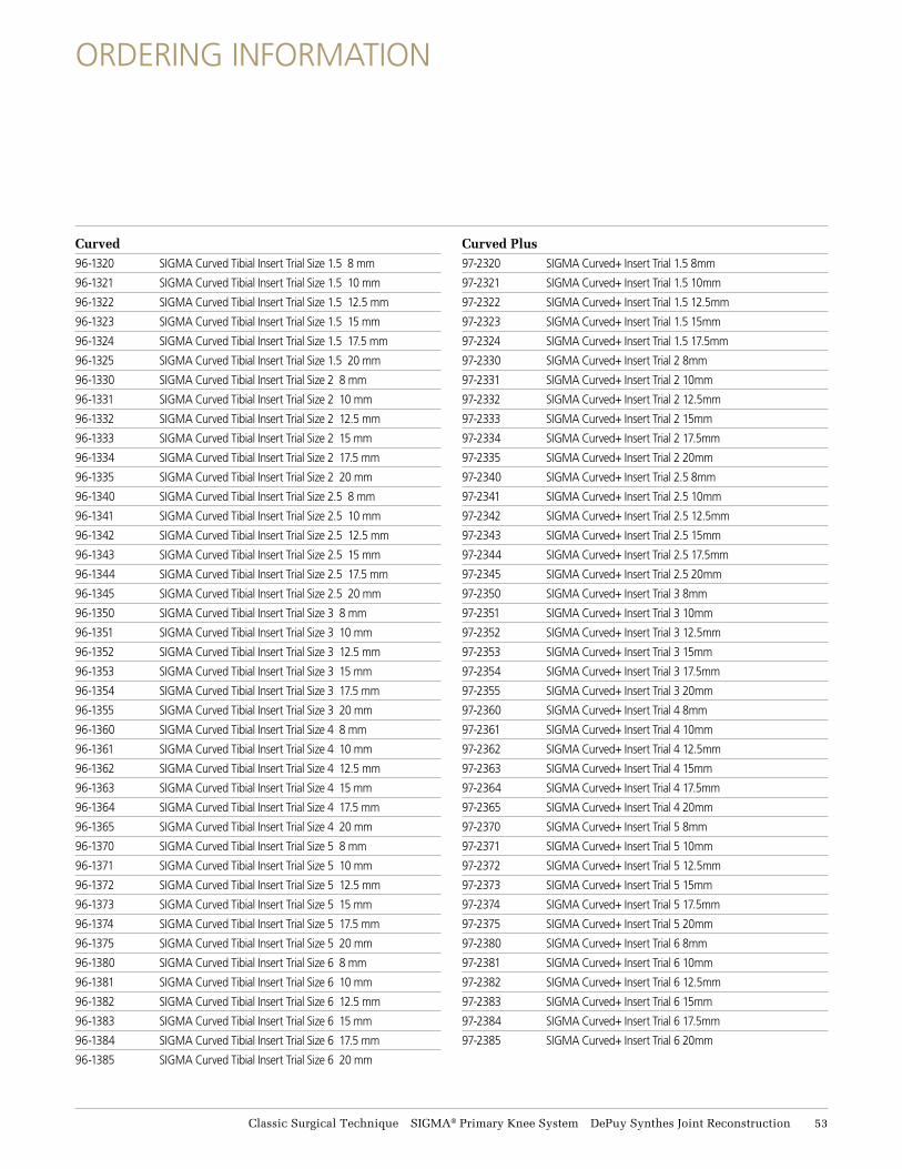
Curved 96-1320 SIGMA Curved Tibial Insert Trial Size 1.5 8 mm
96-1321 SIGMA Curved Tibial Insert Trial Size 1.5 10 mm
96-1322 SIGMA Curved Tibial Insert Trial Size 1.5 12.5 mm
96-1323 SIGMA Curved Tibial Insert Trial Size 1.5 15 mm
96-1324 SIGMA Curved Tibial Insert Trial Size 1.5 17.5 mm
96-1325 SIGMA Curved Tibial Insert Trial Size 1.5 20 mm
96-1330 SIGMA Curved Tibial Insert Trial Size 2 8 mm
96-1331 SIGMA Curved Tibial Insert Trial Size 2 10 mm
96-1332 SIGMA Curved Tibial Insert Trial Size 2 12.5 mm
96-1333 SIGMA Curved Tibial Insert Trial Size 2 15 mm
96-1334 SIGMA Curved Tibial Insert Trial Size 2 17.5 mm
96-1335 SIGMA Curved Tibial Insert Trial Size 2 20 mm
96-1340 SIGMA Curved Tibial Insert Trial Size 2.5 8 mm
96-1341 SIGMA Curved Tibial Insert Trial Size 2.5 10 mm
96-1342 SIGMA Curved Tibial Insert Trial Size 2.5 12.5 mm
96-1343 SIGMA Curved Tibial Insert Trial Size 2.5 15 mm
96-1344 SIGMA Curved Tibial Insert Trial Size 2.5 17.5 mm
96-1345 SIGMA Curved Tibial Insert Trial Size 2.5 20 mm
96-1350 SIGMA Curved Tibial Insert Trial Size 3 8 mm
96-1351 SIGMA Curved Tibial Insert Trial Size 3 10 mm
96-1352 SIGMA Curved Tibial Insert Trial Size 3 12.5 mm
96-1353 SIGMA Curved Tibial Insert Trial Size 3 15 mm
96-1354 SIGMA Curved Tibial Insert Trial Size 3 17.5 mm
96-1355 SIGMA Curved Tibial Insert Trial Size 3 20 mm
96-1360 SIGMA Curved Tibial Insert Trial Size 4 8 mm
96-1361 SIGMA Curved Tibial Insert Trial Size 4 10 mm
96-1362 SIGMA Curved Tibial Insert Trial Size 4 12.5 mm
96-1363 SIGMA Curved Tibial Insert Trial Size 4 15 mm
96-1364 SIGMA Curved Tibial Insert Trial Size 4 17.5 mm
96-1365 SIGMA Curved Tibial Insert Trial Size 4 20 mm
96-1370 SIGMA Curved Tibial Insert Trial Size 5 8 mm
96-1371 SIGMA Curved Tibial Insert Trial Size 5 10 mm
96-1372 SIGMA Curved Tibial Insert Trial Size 5 12.5 mm
96-1373 SIGMA Curved Tibial Insert Trial Size 5 15 mm
96-1374 SIGMA Curved Tibial Insert Trial Size 5 17.5 mm
96-1375 SIGMA Curved Tibial Insert Trial Size 5 20 mm
96-1380 SIGMA Curved Tibial Insert Trial Size 6 8 mm
96-1381 SIGMA Curved Tibial Insert Trial Size 6 10 mm
96-1382 SIGMA Curved Tibial Insert Trial Size 6 12.5 mm
96-1383 SIGMA Curved Tibial Insert Trial Size 6 15 mm
96-1384 SIGMA Curved Tibial Insert Trial Size 6 17.5 mm
96-1385 SIGMA Curved Tibial Insert Trial Size 6 20 mm
Curved Plus97-2320 SIGMA Curved+ Insert Trial 1.5 8mm
97-2321 SIGMA Curved+ Insert Trial 1.5 10mm
97-2322 SIGMA Curved+ Insert Trial 1.5 12.5mm
97-2323 SIGMA Curved+ Insert Trial 1.5 15mm
97-2324 SIGMA Curved+ Insert Trial 1.5 17.5mm
97-2330 SIGMA Curved+ Insert Trial 2 8mm
97-2331 SIGMA Curved+ Insert Trial 2 10mm
97-2332 SIGMA Curved+ Insert Trial 2 12.5mm
97-2333 SIGMA Curved+ Insert Trial 2 15mm
97-2334 SIGMA Curved+ Insert Trial 2 17.5mm
97-2335 SIGMA Curved+ Insert Trial 2 20mm
97-2340 SIGMA Curved+ Insert Trial 2.5 8mm
97-2341 SIGMA Curved+ Insert Trial 2.5 10mm
97-2342 SIGMA Curved+ Insert Trial 2.5 12.5mm
97-2343 SIGMA Curved+ Insert Trial 2.5 15mm
97-2344 SIGMA Curved+ Insert Trial 2.5 17.5mm
97-2345 SIGMA Curved+ Insert Trial 2.5 20mm
97-2350 SIGMA Curved+ Insert Trial 3 8mm
97-2351 SIGMA Curved+ Insert Trial 3 10mm
97-2352 SIGMA Curved+ Insert Trial 3 12.5mm
97-2353 SIGMA Curved+ Insert Trial 3 15mm
97-2354 SIGMA Curved+ Insert Trial 3 17.5mm
97-2355 SIGMA Curved+ Insert Trial 3 20mm
97-2360 SIGMA Curved+ Insert Trial 4 8mm
97-2361 SIGMA Curved+ Insert Trial 4 10mm
97-2362 SIGMA Curved+ Insert Trial 4 12.5mm
97-2363 SIGMA Curved+ Insert Trial 4 15mm
97-2364 SIGMA Curved+ Insert Trial 4 17.5mm
97-2365 SIGMA Curved+ Insert Trial 4 20mm
97-2370 SIGMA Curved+ Insert Trial 5 8mm
97-2371 SIGMA Curved+ Insert Trial 5 10mm
97-2372 SIGMA Curved+ Insert Trial 5 12.5mm
97-2373 SIGMA Curved+ Insert Trial 5 15mm
97-2374 SIGMA Curved+ Insert Trial 5 17.5mm
97-2375 SIGMA Curved+ Insert Trial 5 20mm
97-2380 SIGMA Curved+ Insert Trial 6 8mm
97-2381 SIGMA Curved+ Insert Trial 6 10mm
97-2382 SIGMA Curved+ Insert Trial 6 12.5mm
97-2383 SIGMA Curved+ Insert Trial 6 15mm
97-2384 SIGMA Curved+ Insert Trial 6 17.5mm
97-2385 SIGMA Curved+ Insert Trial 6 20mm
Classic Surgical Technique SIGMA® Primary Knee System DePuy Synthes Joint Reconstruction 53
ORDERING INFORMATION
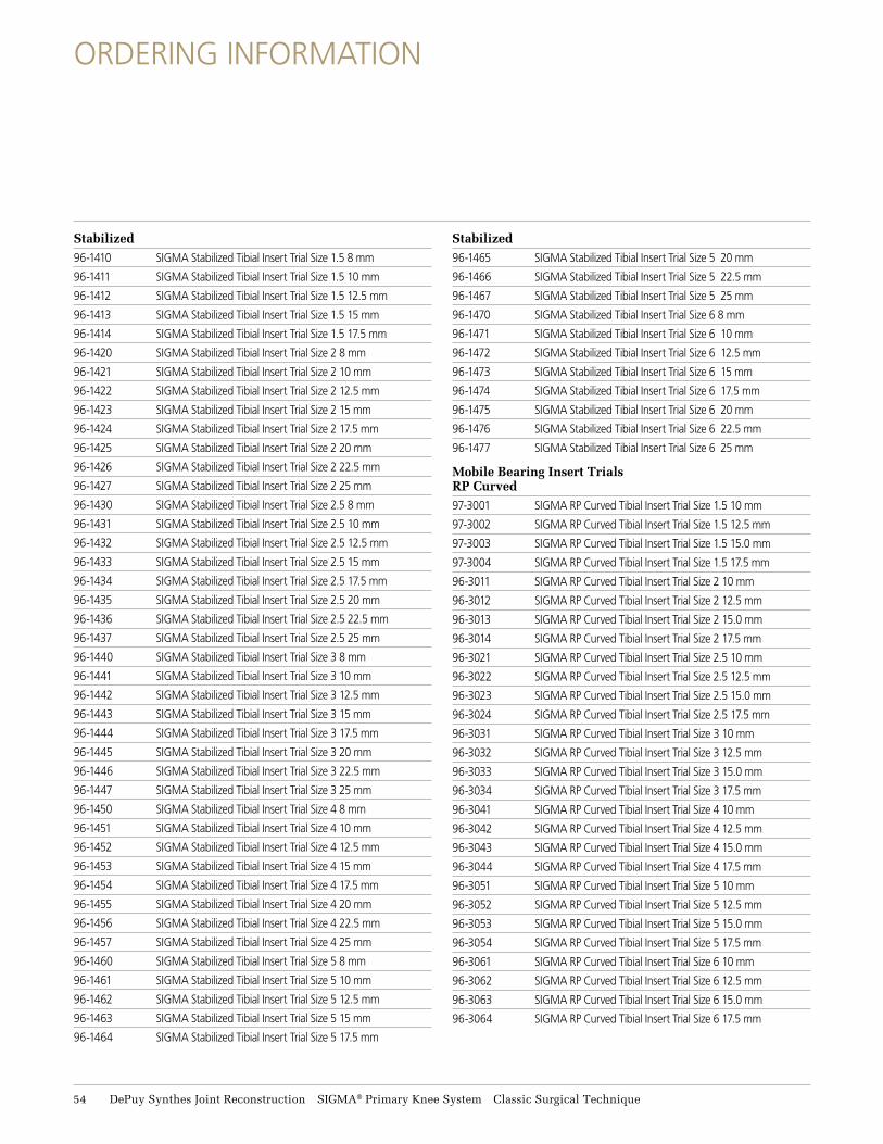
Stabilized96-1410 SIGMA Stabilized Tibial Insert Trial Size 1.5 8 mm
96-1411 SIGMA Stabilized Tibial Insert Trial Size 1.5 10 mm
96-1412 SIGMA Stabilized Tibial Insert Trial Size 1.5 12.5 mm
96-1413 SIGMA Stabilized Tibial Insert Trial Size 1.5 15 mm
96-1414 SIGMA Stabilized Tibial Insert Trial Size 1.5 17.5 mm
96-1420 SIGMA Stabilized Tibial Insert Trial Size 2 8 mm
96-1421 SIGMA Stabilized Tibial Insert Trial Size 2 10 mm
96-1422 SIGMA Stabilized Tibial Insert Trial Size 2 12.5 mm
96-1423 SIGMA Stabilized Tibial Insert Trial Size 2 15 mm
96-1424 SIGMA Stabilized Tibial Insert Trial Size 2 17.5 mm
96-1425 SIGMA Stabilized Tibial Insert Trial Size 2 20 mm
96-1426 SIGMA Stabilized Tibial Insert Trial Size 2 22.5 mm
96-1427 SIGMA Stabilized Tibial Insert Trial Size 2 25 mm
96-1430 SIGMA Stabilized Tibial Insert Trial Size 2.5 8 mm
96-1431 SIGMA Stabilized Tibial Insert Trial Size 2.5 10 mm
96-1432 SIGMA Stabilized Tibial Insert Trial Size 2.5 12.5 mm
96-1433 SIGMA Stabilized Tibial Insert Trial Size 2.5 15 mm
96-1434 SIGMA Stabilized Tibial Insert Trial Size 2.5 17.5 mm
96-1435 SIGMA Stabilized Tibial Insert Trial Size 2.5 20 mm
96-1436 SIGMA Stabilized Tibial Insert Trial Size 2.5 22.5 mm
96-1437 SIGMA Stabilized Tibial Insert Trial Size 2.5 25 mm
96-1440 SIGMA Stabilized Tibial Insert Trial Size 3 8 mm
96-1441 SIGMA Stabilized Tibial Insert Trial Size 3 10 mm
96-1442 SIGMA Stabilized Tibial Insert Trial Size 3 12.5 mm
96-1443 SIGMA Stabilized Tibial Insert Trial Size 3 15 mm
96-1444 SIGMA Stabilized Tibial Insert Trial Size 3 17.5 mm
96-1445 SIGMA Stabilized Tibial Insert Trial Size 3 20 mm
96-1446 SIGMA Stabilized Tibial Insert Trial Size 3 22.5 mm
96-1447 SIGMA Stabilized Tibial Insert Trial Size 3 25 mm
96-1450 SIGMA Stabilized Tibial Insert Trial Size 4 8 mm
96-1451 SIGMA Stabilized Tibial Insert Trial Size 4 10 mm
96-1452 SIGMA Stabilized Tibial Insert Trial Size 4 12.5 mm
96-1453 SIGMA Stabilized Tibial Insert Trial Size 4 15 mm
96-1454 SIGMA Stabilized Tibial Insert Trial Size 4 17.5 mm
96-1455 SIGMA Stabilized Tibial Insert Trial Size 4 20 mm
96-1456 SIGMA Stabilized Tibial Insert Trial Size 4 22.5 mm
96-1457 SIGMA Stabilized Tibial Insert Trial Size 4 25 mm
96-1460 SIGMA Stabilized Tibial Insert Trial Size 5 8 mm
96-1461 SIGMA Stabilized Tibial Insert Trial Size 5 10 mm
96-1462 SIGMA Stabilized Tibial Insert Trial Size 5 12.5 mm
96-1463 SIGMA Stabilized Tibial Insert Trial Size 5 15 mm
96-1464 SIGMA Stabilized Tibial Insert Trial Size 5 17.5 mm
Stabilized96-1465 SIGMA Stabilized Tibial Insert Trial Size 5 20 mm
96-1466 SIGMA Stabilized Tibial Insert Trial Size 5 22.5 mm
96-1467 SIGMA Stabilized Tibial Insert Trial Size 5 25 mm
96-1470 SIGMA Stabilized Tibial Insert Trial Size 6 8 mm
96-1471 SIGMA Stabilized Tibial Insert Trial Size 6 10 mm
96-1472 SIGMA Stabilized Tibial Insert Trial Size 6 12.5 mm
96-1473 SIGMA Stabilized Tibial Insert Trial Size 6 15 mm
96-1474 SIGMA Stabilized Tibial Insert Trial Size 6 17.5 mm
96-1475 SIGMA Stabilized Tibial Insert Trial Size 6 20 mm
96-1476 SIGMA Stabilized Tibial Insert Trial Size 6 22.5 mm
96-1477 SIGMA Stabilized Tibial Insert Trial Size 6 25 mm
Mobile Bearing Insert Trials RP Curved97-3001 SIGMA RP Curved Tibial Insert Trial Size 1.5 10 mm
97-3002 SIGMA RP Curved Tibial Insert Trial Size 1.5 12.5 mm
97-3003 SIGMA RP Curved Tibial Insert Trial Size 1.5 15.0 mm
97-3004 SIGMA RP Curved Tibial Insert Trial Size 1.5 17.5 mm
96-3011 SIGMA RP Curved Tibial Insert Trial Size 2 10 mm
96-3012 SIGMA RP Curved Tibial Insert Trial Size 2 12.5 mm
96-3013 SIGMA RP Curved Tibial Insert Trial Size 2 15.0 mm
96-3014 SIGMA RP Curved Tibial Insert Trial Size 2 17.5 mm
96-3021 SIGMA RP Curved Tibial Insert Trial Size 2.5 10 mm
96-3022 SIGMA RP Curved Tibial Insert Trial Size 2.5 12.5 mm
96-3023 SIGMA RP Curved Tibial Insert Trial Size 2.5 15.0 mm
96-3024 SIGMA RP Curved Tibial Insert Trial Size 2.5 17.5 mm
96-3031 SIGMA RP Curved Tibial Insert Trial Size 3 10 mm
96-3032 SIGMA RP Curved Tibial Insert Trial Size 3 12.5 mm
96-3033 SIGMA RP Curved Tibial Insert Trial Size 3 15.0 mm
96-3034 SIGMA RP Curved Tibial Insert Trial Size 3 17.5 mm
96-3041 SIGMA RP Curved Tibial Insert Trial Size 4 10 mm
96-3042 SIGMA RP Curved Tibial Insert Trial Size 4 12.5 mm
96-3043 SIGMA RP Curved Tibial Insert Trial Size 4 15.0 mm
96-3044 SIGMA RP Curved Tibial Insert Trial Size 4 17.5 mm
96-3051 SIGMA RP Curved Tibial Insert Trial Size 5 10 mm
96-3052 SIGMA RP Curved Tibial Insert Trial Size 5 12.5 mm
96-3053 SIGMA RP Curved Tibial Insert Trial Size 5 15.0 mm
96-3054 SIGMA RP Curved Tibial Insert Trial Size 5 17.5 mm
96-3061 SIGMA RP Curved Tibial Insert Trial Size 6 10 mm
96-3062 SIGMA RP Curved Tibial Insert Trial Size 6 12.5 mm
96-3063 SIGMA RP Curved Tibial Insert Trial Size 6 15.0 mm
96-3064 SIGMA RP Curved Tibial Insert Trial Size 6 17.5 mm
54 DePuy Synthes Joint Reconstruction SIGMA® Primary Knee System Classic Surgical Technique
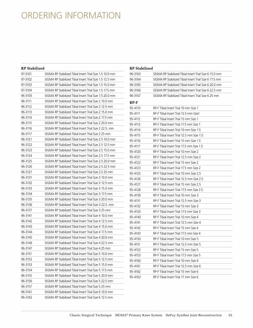
RP Stabilized 97-3101 SIGMA RP Stabilized Tibial Insert Trial Size 1.5 10.0 mm
97-3102 SIGMA RP Stabilized Tibial Insert Trial Size 1.5 12.5 mm
97-3103 SIGMA RP Stabilized Tibial Insert Trial Size 1.5 15.0 mm
97-3104 SIGMA RP Stabilized Tibial Insert Trial Size 1.5 17.5 mm
96-3105 SIGMA RP Stabilized Tibial Insert Trial Size 1.5 20.0 mm
96-3111 SIGMA RP Stabilized Tibial Insert Trial Size 2 10.0 mm
96-3112 SIGMA RP Stabilized Tibial Insert Trial Size 2 12.5 mm
96-3113 SIGMA RP Stabilized Tibial Insert Trial Size 2 15.0 mm
96-3114 SIGMA RP Stabilized Tibial Insert Trial Size 2 17.5 mm
96-3115 SIGMA RP Stabilized Tibial Insert Trial Size 2 20.0 mm
96-3116 SIGMA RP Stabilized Tibial Insert Trial Size 2 22.5. mm
96-3117 SIGMA RP Stabilized Tibial Insert Trial Size 2 25 mm
96-3121 SIGMA RP Stabilized Tibial Insert Trial Size 2.5 10.0 mm
96-3122 SIGMA RP Stabilized Tibial Insert Trial Size 2.5 12.5 mm
96-3123 SIGMA RP Stabilized Tibial Insert Trial Size 2.5 15.0 mm
96-3124 SIGMA RP Stabilized Tibial Insert Trial Size 2.5 17.5 mm
96-3125 SIGMA RP Stabilized Tibial Insert Trial Size 2.5 20.0 mm
96-3126 SIGMA RP Stabilized Tibial Insert Trial Size 2.5 22.5 mm
96-3127 SIGMA RP Stabilized Tibial Insert Trial Size 2.5 25 mm
96-3131 SIGMA RP Stabilized Tibial Insert Trial Size 3 10.0 mm
96-3132 SIGMA RP Stabilized Tibial Insert Trial Size 3 12.5 mm
96-3133 SIGMA RP Stabilized Tibial Insert Trial Size 3 15.0 mm
96-3134 SIGMA RP Stabilized Tibial Insert Trial Size 3 17.5 mm
96-3135 SIGMA RP Stabilized Tibial Insert Trial Size 3 20.0 mm
96-3136 SIGMA RP Stabilized Tibial Insert Trial Size 3 22.5. mm
96-3137 SIGMA RP Stabilized Tibial Insert Trial Size 3 25 mm
96-3141 SIGMA RP Stabilized Tibial Insert Trial Size 4 10.0 mm
96-3142 SIGMA RP Stabilized Tibial Insert Trial Size 4 12.5 mm
96-3143 SIGMA RP Stabilized Tibial Insert Trial Size 4 15.0 mm
96-3144 SIGMA RP Stabilized Tibial Insert Trial Size 4 17.5 mm
96-3145 SIGMA RP Stabilized Tibial Insert Trial Size 4 20.0 mm
96-3146 SIGMA RP Stabilized Tibial Insert Trial Size 4 22.5 mm
96-3147 SIGMA RP Stabilized Tibial Insert Trial Size 4 25 mm
96-3151 SIGMA RP Stabilized Tibial Insert Trial Size 5 10.0 mm
96-3152 SIGMA RP Stabilized Tibial Insert Trial Size 5 12.5 mm
96-3153 SIGMA RP Stabilized Tibial Insert Trial Size 5 15.0 mm
96-3154 SIGMA RP Stabilized Tibial Insert Trial Size 5 17.5 mm
96-3155 SIGMA RP Stabilized Tibial Insert Trial Size 5 20.0 mm
96-3156 SIGMA RP Stabilized Tibial Insert Trial Size 5 22.5 mm
96-3157 SIGMA RP Stabilized Tibial Insert Trial Size 5 25 mm
96-3161 SIGMA RP Stabilized Tibial Insert Trial Size 6 10.0 mm
96-3162 SIGMA RP Stabilized Tibial Insert Trial Size 6 12.5 mm
RP Stabilized 96-3163 SIGMA RP Stabilized Tibial Insert Trial Size 6 15.0 mm
96-3164 SIGMA RP Stabilized Tibial Insert Trial Size 6 17.5 mm
96-3165 SIGMA RP Stabilized Tibial Insert Trial Size 6 20.0 mm
96-3166 SIGMA RP Stabilized Tibial Insert Trial Size 6 22.5 mm
96-3167 SIGMA RP Stabilized Tibial Insert Trial Size 6 25 mm
RP-F 95-4110 RP-F Tibial Insert Trial 10 mm Size 1
95-4111 RP-F Tibial Insert Trial 12.5 mm Size1
95-4112 RP-F Tibial Insert Trial 15 mm Size 1
95-4113 RP-F Tibial Insert Trial 17.5 mm Size 1
95-4114 RP-F Tibial Insert Trial 10 mm Size 1.5
95-4115 RP-F Tibial Insert Trial 12.5 mm Size 1.5
95-4116 RP-F Tibial Insert Trial 15 mm Size 1.5
95-4117 RP-F Tibial Insert Trial 17.5 mm Size 1.5
95-4120 RP-F Tibial Insert Trial 10 mm Size 2
95-4121 RP-F Tibial Insert Trial 12.5 mm Size 2
95-4122 RP-F Tibial Insert Trial 15 mm Size 2
95-4123 RP-F Tibial Insert Trial 17.5 mm Size 2
95-4125 RP-F Tibial Insert Trial 10 mm Size 2.5
95-4126 RP-F Tibial Insert Trial 12.5 mm Size 2.5
95-4127 RP-F Tibial Insert Trial 15 mm Size 2.5
95-4128 RP-F Tibial Insert Trial 17.5 mm Size 2.5
95-4130 RP-F Tibial Insert Trial 10 mm Size 3
95-4131 RP-F Tibial Insert Trial 12.5 mm Size 3
95-4132 RP-F Tibial Insert Trial 15 mm Size 3
95-4133 RP-F Tibial Insert Trial 17.5 mm Size 3
95-4140 RP-F Tibial Insert Trial 10 mm Size 4
95-4141 RP-F Tibial Insert Trial 12.5 mm Size 4
95-4142 RP-F Tibial Insert Trial 15 mm Size 4
95-4143 RP-F Tibial Insert Trial 17.5 mm Size 4
95-4150 RP-F Tibial Insert Trial 10 mm Size 5
95-4151 RP-F Tibial Insert Trial 12.5 mm Size 5
95-4152 RP-F Tibial Insert Trial 15 mm Size 5
95-4153 RP-F Tibial Insert Trial 17.5 mm Size 5
95-4160 RP-F Tibial Insert Trial 10 mm Size 6
95-4161 RP-F Tibial Insert Trial 12.5 mm Size 6
95-4162 RP-F Tibial Insert Trial 15 mm Size 6
95-4163 RP-F Tibial Insert Trial 17 mm Size 6
ORDERING INFORMATION
Classic Surgical Technique SIGMA® Primary Knee System DePuy Synthes Joint Reconstruction 55

Patella Resection 9505-01-121 SIGMA HP Patella Resection Guide
9505-01-242 SIGMA HP Patella Resection Stylus 32-38 mm
9505-01-243 SIGMA HP Patella Resection Stylus 41 mm
9505-01-247 SIGMA HP Patella Resection Stylus 12 mm Remnant
9505-01-923 HP Patella Wafer Small
9505-01-623 HP Patella Wafer Large
86-9188 Patella Caliper
86-5035 Patella Clamp
86-8801 Oval Patella Drill w/Hudson End
96-1100 PFC* SIGMA Oval/Dome Patella Trial 3 Peg 32 mm
96-1101 PFC* SIGMA Oval/Dome Patella Trial 3 Peg 35 mm
96-1102 PFC* SIGMA Oval/Dome Patella Trial 3 Peg 38 mm
96-1103 PFC* SIGMA Oval/Dome Patella Trial 3 Peg 41 mm
96-6601 Patellar Drill Guide 38 mm & 41 mm
96-6602 Patellar Drill Guide 32 mm & 35 mm
Spacer blocks Fixed Bearing9505-02-105 SIGMA HP F.B.T. Spacer Block 8 mm
9505-02-106 SIGMA HP F.B.T. Spacer Block 10 mm
9505-02-107 SIGMA HP F.B.T. Spacer Block 12.5 mm
9505-02-108 SIGMA HP F.B.T. Spacer Block 15 mm
9505-02-109 SIGMA HP F.B.T. Spacer Block 17.5 mm
9505-02-110 SIGMA HP F.B.T. Spacer Block 20 mm
9505-02-111 SIGMA HP F.B.T. Spacer Block 22.5 mm
9505-02-112 SIGMA HP F.B.T. Spacer Block 25 mm
9505-02-113 SIGMA HP F.B.T. Spacer Block 30 mm
9505-02-193 Flexion/ Extension CAP Size 6
Mobile Bearing 9505-02-114 HP MBT Spacer Block 10 mm
9505-02-115 HP MBT Spacer Block 12.5 mm
9505-02-116 HP MBT Spacer Block 15 mm
9505-02-117 HP MBT Spacer Block 17.5 mm
9505-02-118 HP MBT Spacer Block 20 mm
9505-02-119 HP MBT Spacer Block 22.5 mm
9505-02-120 HP MBT Spacer Block 25 mm
9505-02-121 HP MBT Spacer Block 30 mm
9505-02-193 Flexion/Extension CAP Size 6
RP-F 9505-02-104 SIGMA RP-F HP Flex Shim Size 1
9505-02-100 SIGMA RP-F HP Flex Shim Size 1.5
9505-02-101 SIGMA RP-F HP Flex Shim Size 2
9505-02-102 SIGMA RP-F HP Flex Shim Size 2.5-5
9505-02-103 SIGMA RP-F HP Flex Shim Size 6
9505-02-193 Flexion/ Extension CAP Size 6
Pinning 9505-02-070 HP Pin Impactor/Extractor
9505-02-071 HP Power Pin Driver
9505-02-072 HP Quick Pin Drills
9505-02-073 HP Quick Pin Drills Headed
9505-02-088 HP Threaded Pins
9505-02-089 HP Threaded Pins Headed
2267-12-000 Smooth 3 Inch Pins (5 Pack)
9505-02-300 SIGMA HP Quick Drill Pins-Sterile
9505-02-302 SIGMA HP Threaded Pins-Sterile
9505-02-303 SIGMA HP Threaded Pins Headed-Sterile
Insertion Femur9505-01-218 SIGMA HP Femoral Notch Impactor
9505-01-171 HP Femoral Impactor/Extractor
9505-01-308 HP Slap Hammer
9505-01-305 HP Universal Handle
Mobile Bearing Tibia9505-01-558 MBT Tibial Impactor
96-5383 MBT Tray Impactor
9505-01-559 MBT Tibial Impactor Replacement Parts
Fixed Bearing Tibia9505-01-306 SIGMA FB Tibial Impactor
2581-11-000 F.B.T. Tray Inserter
96-6385 F.B.T. Poly PS
9505-01-170 SIGMA F.B.T. Tibia Impactor Replacement Parts
96-6384 F.B.T. Tray Inserter
ORDERING INFORMATION
56 DePuy Synthes Joint Reconstruction SIGMA® Primary Knee System Classic Surgical Technique
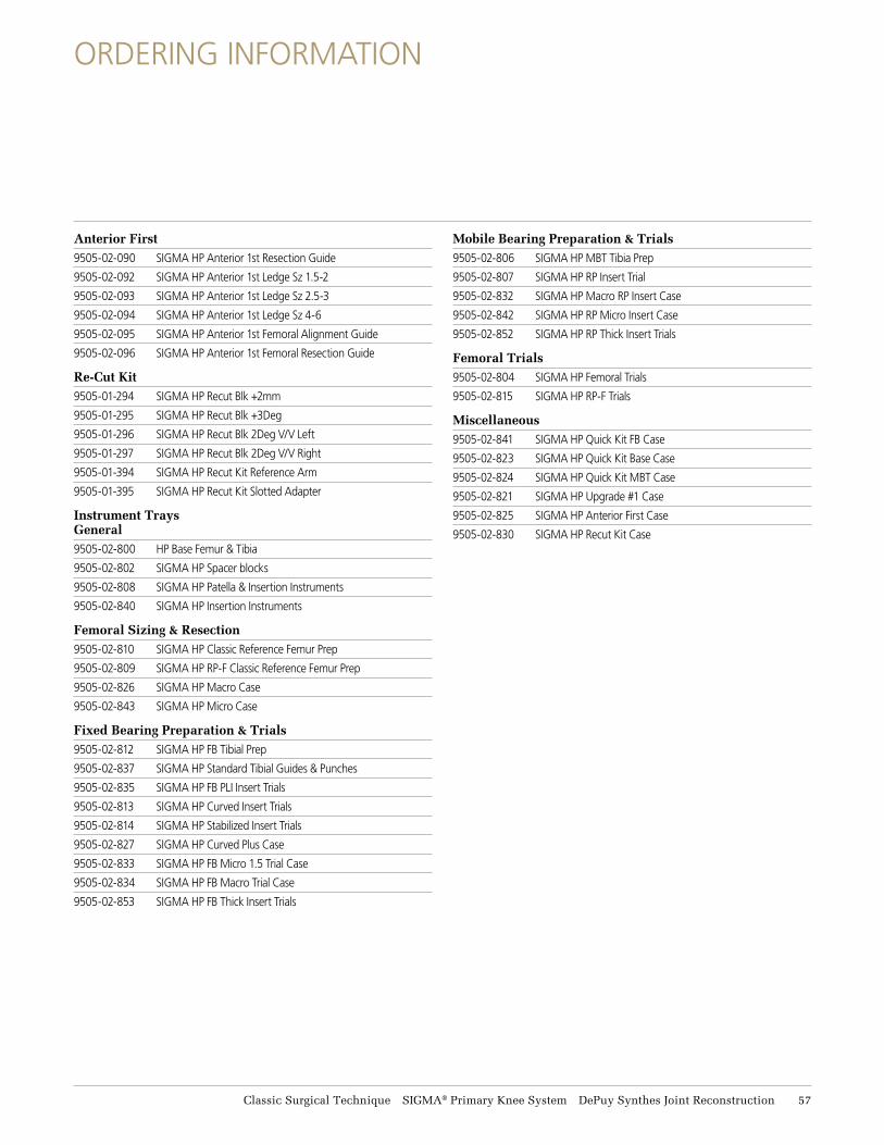
Anterior First9505-02-090 SIGMA HP Anterior 1st Resection Guide
9505-02-092 SIGMA HP Anterior 1st Ledge Sz 1.5-2
9505-02-093 SIGMA HP Anterior 1st Ledge Sz 2.5-3
9505-02-094 SIGMA HP Anterior 1st Ledge Sz 4-6
9505-02-095 SIGMA HP Anterior 1st Femoral Alignment Guide
9505-02-096 SIGMA HP Anterior 1st Femoral Resection Guide
Re-Cut Kit9505-01-294 SIGMA HP Recut Blk +2mm
9505-01-295 SIGMA HP Recut Blk +3Deg
9505-01-296 SIGMA HP Recut Blk 2Deg V/V Left
9505-01-297 SIGMA HP Recut Blk 2Deg V/V Right
9505-01-394 SIGMA HP Recut Kit Reference Arm
9505-01-395 SIGMA HP Recut Kit Slotted Adapter
Instrument Trays General9505-02-800 HP Base Femur & Tibia
9505-02-802 SIGMA HP Spacer blocks
9505-02-808 SIGMA HP Patella & Insertion Instruments
9505-02-840 SIGMA HP Insertion Instruments
Femoral Sizing & Resection9505-02-810 SIGMA HP Classic Reference Femur Prep
9505-02-809 SIGMA HP RP-F Classic Reference Femur Prep
9505-02-826 SIGMA HP Macro Case
9505-02-843 SIGMA HP Micro Case
Fixed Bearing Preparation & Trials9505-02-812 SIGMA HP FB Tibial Prep
9505-02-837 SIGMA HP Standard Tibial Guides & Punches
9505-02-835 SIGMA HP FB PLI Insert Trials
9505-02-813 SIGMA HP Curved Insert Trials
9505-02-814 SIGMA HP Stabilized Insert Trials
9505-02-827 SIGMA HP Curved Plus Case
9505-02-833 SIGMA HP FB Micro 1.5 Trial Case
9505-02-834 SIGMA HP FB Macro Trial Case
9505-02-853 SIGMA HP FB Thick Insert Trials
Mobile Bearing Preparation & Trials9505-02-806 SIGMA HP MBT Tibia Prep
9505-02-807 SIGMA HP RP Insert Trial
9505-02-832 SIGMA HP Macro RP Insert Case
9505-02-842 SIGMA HP RP Micro Insert Case
9505-02-852 SIGMA HP RP Thick Insert Trials
Femoral Trials9505-02-804 SIGMA HP Femoral Trials
9505-02-815 SIGMA HP RP-F Trials
Miscellaneous9505-02-841 SIGMA HP Quick Kit FB Case
9505-02-823 SIGMA HP Quick Kit Base Case
9505-02-824 SIGMA HP Quick Kit MBT Case
9505-02-821 SIGMA HP Upgrade #1 Case
9505-02-825 SIGMA HP Anterior First Case
9505-02-830 SIGMA HP Recut Kit Case
ORDERING INFORMATION
Classic Surgical Technique SIGMA® Primary Knee System DePuy Synthes Joint Reconstruction 57
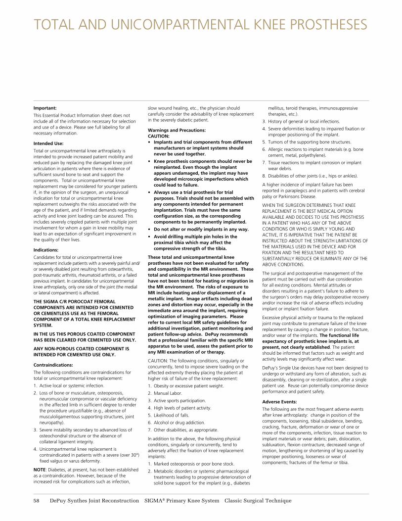
TOTAL AND UNICOMPARTMENTAL KNEE PROSTHESES
Important:
This Essential Product Information sheet does not include all of the information necessary for selection and use of a device. Please see full labeling for all necessary information.
Intended Use:
Total or unicompartmental knee arthroplasty is intended to provide increased patient mobility and reduced pain by replacing the damaged knee joint articulation in patients where there is evidence of sufficient sound bone to seat and support the components. Total or unicompartmental knee replacement may be considered for younger patients if, in the opinion of the surgeon, an unequivocal indication for total or unicompartmental knee replacement outweighs the risks associated with the age of the patient, and if limited demands regarding activity and knee joint loading can be assured. This includes severely crippled patients with multiple joint involvement for whom a gain in knee mobility may lead to an expectation of significant improvement in the quality of their lives.
Indications:
Candidates for total or unicompartmental knee replacement include patients with a severely painful and/or severely disabled joint resulting from osteoarthritis, post-traumatic arthritis, rheumatoid arthritis, or a failed previous implant. In candidates for unicompartmental knee arthroplasty, only one side of the joint (the medial or lateral compartment) is affected.
THE SIGMA C/R POROCOAT FEMORAL COMPONENTS ARE INTENDED FOR CEMENTED OR CEMENTLESS USE AS THE FEMORAL COMPONENT OF A TOTAL KNEE REPLACEMENT SYSTEM.
IN THE US THIS POROUS COATED COMPONENT HAS BEEN CLEARED FOR CEMENTED USE ONLY.
ANY NON-POROUS COATED COMPONENT IS INTENDED FOR CEMENTED USE ONLY.
Contraindications:
The following conditions are contraindications for total or unicompartmental knee replacement:
1. Active local or systemic infection.
2. Loss of bone or musculature, osteoporosis, neuromuscular compromise or vascular deficiency in the affected limb in sufficient degree to render the procedure unjustifiable (e.g., absence of musculoligamentous supporting structures, joint neuropathy).
3. Severe instability secondary to advanced loss of osteochondral structure or the absence of collateral ligament integrity.
4. Unicompartmental knee replacement is contraindicated in patients with a severe (over 30°) fixed valgus or varus deformity.
NOTE: Diabetes, at present, has not been established as a contraindication. However, because of the increased risk for complications such as infection,
slow wound healing, etc., the physician should carefully consider the advisability of knee replacement in the severely diabetic patient.
Warnings and Precautions:CAUTION:• Implants and trial components from different
manufacturers or implant systems should never be used together.
• Knee prosthesis components should never be reimplanted. Even though the implant appears undamaged, the implant may have developed microscopic imperfections which could lead to failure.
• Always use a trial prosthesis for trial purposes. Trials should not be assembled with any components intended for permanent implantation. Trials must have the same configuration size, as the corresponding components to be permanently implanted.
• Do not alter or modify implants in any way.
• Avoid drilling multiple pin holes in the proximal tibia which may affect the compressive strength of the tibia.
These total and unicompartmental knee prostheses have not been evaluated for safety and compatibility in the MR environment. These total and unicompartmental knee prostheses have not been tested for heating or migration in the MR environment. The risks of exposure to MR include heating and/or displacement of a metallic implant. Image artifacts including dead zones and distortion may occur, especially in the immediate area around the implant, requiring optimization of imaging parameters. Please refer to current local MR safety guidelines for additional investigation, patient monitoring and patient follow-up advice. DePuy recommends that a professional familiar with the specific MRI apparatus to be used, assess the patient prior to any MRI examination of or therapy.
CAUTION: The following conditions, singularly or concurrently, tend to impose severe loading on the affected extremity thereby placing the patient at higher risk of failure of the knee replacement:
1. Obesity or excessive patient weight.
2. Manual Labor.
3. Active sports participation.
4. High levels of patient activity.
5. Likelihood of falls.
6. Alcohol or drug addiction.
7. Other disabilities, as appropriate.
In addition to the above, the following physical conditions, singularly or concurrently, tend to adversely affect the fixation of knee replacement implants:
1. Marked osteoporosis or poor bone stock.
2. Metabolic disorders or systemic pharmacological treatments leading to progressive deterioration of solid bone support for the implant (e.g., diabetes
mellitus, teroid therapies, immunosuppressive therapies, etc.).
3. History of general or local infections.
4. Severe deformities leading to impaired fixation or improper positioning of the implant.
5. Tumors of the supporting bone structures.
6. Allergic reactions to implant materials (e.g. bone cement, metal, polyethylene).
7. Tissue reactions to implant corrosion or implant wear debris.
8. Disabilities of other joints (i.e., hips or ankles).
A higher incidence of implant failure has been reported in paraplegics and in patients with cerebral palsy or Parkinsons Disease.
WHEN THE SURGEON DETERMINES THAT KNEE REPLACEMENT IS THE BEST MEDICAL OPTION AVAILABLE AND DECIDES TO USE THIS PROSTHESIS IN A PATIENT WHO HAS ANY OF THE ABOVE CONDITIONS OR WHO IS SIMPLY YOUNG AND ACTIVE, IT IS IMPERATIVE THAT THE PATIENT BE INSTRUCTED ABOUT THE STRENGTH LIMITATIONS OF THE MATERIALS USED IN THE DEVICE AND FOR FIXATION AND THE RESULTANT NEED TO SUBSTANTIALLY REDUCE OR ELIMINATE ANY OF THE ABOVE CONDITIONS.
The surgical and postoperative management of the patient must be carried out with due consideration for all existing conditions. Mental attitudes or disorders resulting in a patient's failure to adhere to the surgeon's orders may delay postoperative recovery and/or increase the risk of adverse effects including implant or implant fixation failure.
Excessive physical activity or trauma to the replaced joint may contribute to premature failure of the knee replacement by causing a change in position, fracture, and/or wear of the implants. The functional life expectancy of prosthetic knee implants is, at present, not clearly established. The patient should be informed that factors such as weight and activity levels may significantly affect wear.
DePuy’s Single Use devices have not been designed to undergo or withstand any form of alteration, such as disassembly, cleaning or re-sterilization, after a single patient use. Reuse can potentially compromise device performance and patient safety.
Adverse Events:
The following are the most frequent adverse events after knee arthroplasty: change in position of the components, loosening, tibial subsidence, bending, cracking, fracture, deformation or wear of one or more of the components, infection, tissue reaction to implant materials or wear debris; pain, dislocation, subluxation, flexion contracture, decreased range of motion, lengthening or shortening of leg caused by improper positioning, looseness or wear of components; fractures of the femur or tibia.
58 DePuy Synthes Joint Reconstruction SIGMA® Primary Knee System Classic Surgical Technique


DePuy Orthopaedics, Inc.700 Orthopaedic DriveWarsaw, IN 46582T. +1 (800) 366-8143
www.depuysynthes.com
© DePuy Synthes Joint Reconstruction, a division of DOI 2014 0612-89-510 (Rev. 3) 1.5M 0514
Limited Warranty and Disclaimer: DePuy Synthes Joint Reconstruction products are sold with a limited warranty to the original purchaser against defects in workmanship and materials. Any other express or implied warranties, including warranties of merchantability or fitness, are hereby disclaimed.
WARNING: In the USA, this product has labeling limitations. See package insert for complete information.
CAUTION: USA Law restricts these devices to sale by or on the order of a physician.
Not all products are currently available in all markets.