Embed Size (px)
DESCRIPTION
Service Manual for the SIGLENT SDS 1000 CML family of oscilloscopes.
Citation preview
Service Manual
SDS1000CML/CNL/DL Series Digital Oscilloscope
2013 SIGLENT TECHNOLOGIES CO., LTD

SIGLENT
SDS1000CML/CNL/DL Service Manual I
Guaranty and Declaration Copyright
SIGLENT TECHNOLOGIES CO., LTD. All Rights Reserved. Trademark Information
SIGLENT is the registered trademark of SIGLENT TECHNOLOGIES CO.,
LTD Declaration
SIGLENT products are protected by patent law in and outside of P.R.C.
SIGLENT reserves the right to modify or change parts of or all the specifications or pricing policies at company’s sole decision.
Information in this publication replaces all previously corresponding
material. Any way of copying, extracting or translating the contents of this manual
is not allowed without the permission of SIGLENT.
SIGLENT will not be responsible for losses caused by either incidental or consequential in connection with the furnishing, use or performance of this manual as well as any information contained.
Product Certification
SIGLENT guarantees this product conforms to the national and industrial standards in china as well as the ISO9001: 2008 standard and the ISO14001: 2004 standard. Other international standard conformance certification is in
progress.
SIGLENT
II SDS1000CML/CNL/DL Service Manual
General Safety Summary Review the following safety precautions to avoid personal injuries and
prevent damages to this product or any products connected to it. To avoid
potential hazards, use this product only as specified.
Only qualified personnel should perform service procedures. To Avoid Fire or Personal Injuries Use Proper Power Cord Use only the power cord specified for this product
and approved by local state. Avoid Electric Shock To avoid injuries or losses of life, do not connect or
disconnect probes or test leads while they are connected to a voltage source. Ground the Product This product is grounded through the protective terra
conductor of the power line. To avoid electric shock, the grounding conductor
must be connected to the earth. Make sure the instrument is grounded
correctly before connecting its input or output terminals. Connect the Probe Properly Do not connect the probe ground lead to a
high voltage since it has the isobaric electric potential as ground. Observe All Terminal Ratings To avoid fire or shock hazard, observe all
ratings and markers on the instrument and check your manual for more
information about ratings before connecting. Use Proper Fuse Use only the specified fuse. Do Not Operate Without Covers Do not operate this instrument with
covers or panels removed. Avoid Circuit or Wire Exposed Do not touch exposed junctions and
components when the unit is powered.
SIGLENT
SDS1000CML/CNL/DL Service Manual III
Do Not Operate With Suspected Failures If you suspect damage occurs
to this instrument, have it inspected by qualified service personnel before
further operation. Any maintenance, adjustment or replacement especially to
the circuits or accessories should be performed by SIGLENT authorized
personnel. Keep Product Surfaces Clean and Dry Do Not Operate in Wet/Damp Conditions To avoid electric shock, do not
operate the instrument in wet or damp condition. Do Not Operate in an Explosive Atmosphere To avoid injuries or fire
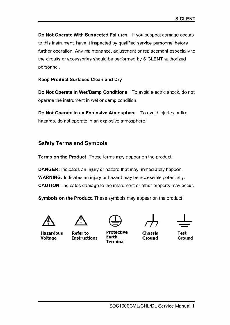
hazards, do not operate in an explosive atmosphere. Safety Terms and Symbols Terms on the Product. These terms may appear on the product: DANGER: Indicates an injury or hazard that may immediately happen.
WARNING: Indicates an injury or hazard may be accessible potentially.
CAUTION: Indicates damage to the instrument or other property may occur. Symbols on the Product. These symbols may appear on the product:
SIGLENT
IV SDS1000CML/CNL/DL Service Manual
Contents
Guaranty and Declaration............................................................................ I General Safety Summary............................................................................ II General Features and Specifications ........................................................1
General Features ....................................................................................1 Specifications..........................................................................................2
Prepare Information ....................................................................................6 Functional checking ................................................................................6
Power-on Inspection .........................................................................6 Default Setup....................................................................................7 Probe Compensation ........................................................................9 Auto Setup......................................................................................10 Self Calibration ...............................................................................10
Interface Test ........................................................................................12 USB Host Test ................................................................................12 USB Device Test.............................................................................14 LAN Test .........................................................................................15 Pass/Fail Test .................................................................................16
Performance Test......................................................................................18 Verify Test Results ..........................................................................19 Self Test..........................................................................................19 Self Calibration ...............................................................................19
To verify DC Gain Accuracy ..................................................................20 To verify Bandwidth...............................................................................21 To verify Time Base Accuracy ...............................................................23 To verify Trigger Sensitivity ...................................................................24
Adjusting Procedures ...............................................................................26 Warming up ....................................................................................26 Self calibration ................................................................................26 Required Equipments .....................................................................26 Software Installation........................................................................26 Adjusting steps ...............................................................................26
Assembly Procedures...............................................................................28 Security Consideration....................................................................28 List of Modules................................................................................28 Required Tools................................................................................29 Disassembly Procedures ................................................................29
Removing the Rear Panel .....................................................................31 Removing the Top Metal Cover.............................................................33 Removing the Rear Metal Cover...........................................................32 Removing the Power Supply Module ....................................................34 Removing the Interface Module ............................... 错误!未定义书签。 Removing the Fan Module....................................................................38 Removing the Main Board.....................................................................36 Removing the Metal Shelf .....................................................................35 Removing the Display Module ..............................................................39 Removing the Front Panel Module........................... 错误!未定义书签。
SIGLENT
SDS1000CML/CNL/DL Service Manual V
Removing the Keypad...........................................................................40 Removing the Front-Panel Knobs.........................................................30
Troubleshooting........................................................................................41 General troubles ...................................................................................41 Troubleshooting the Hardware Failures ................................................43
ESD Precautions ............................................................................43 Required Equipments .....................................................................43 Main Board Drawing .......................................................................44 Troubleshooting Flowchart..............................................................45 Check the Power Supply.................................................................46 Check the Main Board ....................................................................47 Check the Display Module ..............................................................48 Troubleshooting the General Hardware Failures ............................49
Maintenance ..............................................................................................50 Maintain summary.................................................................................50 Inspecting and Care..............................................................................50
General Inspecting..........................................................................50 General Care and Cleaning ............................................................51
Extended Service..................................................... 错误!未定义书签。 Extended Service Details................................... 错误!未定义书签。
Contact SIGLENT .................................................................................53 Replaceable Parts .....................................................................................52

SIGLENT
SDS1000CML/CNL/DL Service Manual 1
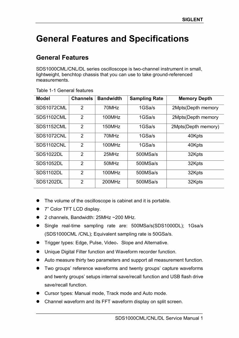
General Features and Specifications General Features SDS1000CML/CNL/DL series oscilloscope is two-channel instrument in small, lightweight, benchtop chassis that you can use to take ground-referenced measurements. Table 1-1 General features Model Channels Bandwidth Sampling Rate Memory Depth
SDS1072CML 2 70MHz 1GSa/s 2Mpts(Depth memory
SDS1102CML 2 100MHz 1GSa/s 2Mpts(Depth memory
SDS1152CML 2 150MHz 1GSa/s 2Mpts(Depth memory)
SDS1072CNL 2 70MHz 1GSa/s 40Kpts
SDS1102CNL 2 100MHz 1GSa/s 40Kpts
SDS1022DL 2 25MHz 500MSa/s 32Kpts
SDS1052DL 2 50MHz 500MSa/s 32Kpts
SDS1102DL 2 100MHz 500MSa/s 32Kpts
SDS1202DL 2 200MHz 500MSa/s 32Kpts
The volume of the oscilloscope is cabinet and it is portable.
7” Color TFT LCD display.
2 channels, Bandwidth: 25MHz ~200 MHz.
Single real-time sampling rate are: 500MSa/s(SDS1000DL); 1Gsa/s
(SDS1000CML /CNL); Equivalent sampling rate is 50GSa/s.
Trigger types: Edge, Pulse, Video,Slope and Alternative.
Unique Digital Filter function and Waveform recorder function.
Auto measure thirty two parameters and support all measurement function.
Two groups’ reference waveforms and twenty groups’ capture waveforms
and twenty groups’ setups internal save/recall function and USB flash drive
save/recall function.
Cursor types: Manual mode, Track mode and Auto mode.
Channel waveform and its FFT waveform display on split screen.
SIGLENT
2 SDS1000CML/CNL/DL Service Manual
Waveform Intensity and Grid Brightness can be adjusted.
Menu display in the form of pop-up that in order to convenience users to
use it.
Multiple Language User Interface.
Support Multilingual online help system.
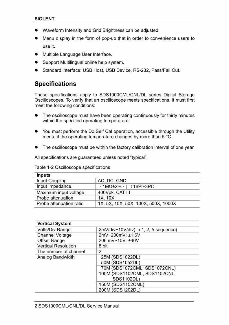
Standard interface: USB Host, USB Device, RS-232, Pass/Fail Out. Specifications These specifications apply to SDS1000CML/CNL/DL series Digital Storage Oscilloscopes. To verify that an oscilloscope meets specifications, it must first meet the following conditions: The oscilloscope must have been operating continuously for thirty minutes
within the specified operating temperature. You must perform the Do Self Cal operation, accessible through the Utility
menu, if the operating temperature changes by more than 5 °C. The oscilloscope must be within the factory calibration interval of one year. All specifications are guaranteed unless noted “typical”. Table 1-2 Oscilloscope specifications
Inputs Input Coupling AC, DC, GND Input Impedance (1MΩ±2%)||(16Pf±3Pf) Maximum input voltage 400Vpk, CAT I I Probe attenuation 1X, 10X Probe attenuation ratio 1X, 5X, 10X, 50X, 100X, 500X, 1000X
Vertical System Volts/Div Range 2mV/div~10V/div( in 1, 2, 5 sequence) Channel Voltage Offset Range
2mV~200mV: ±1.6V 206 mV~10V: ±40V
Vertical Resolution 8 bit The number of channel 2
25M (SDS1022DL) 50M (SDS1052DL) 70M (SDS1072CML, SDS1072CNL)
100M (SDS1102CML, SDS1102CNL, SDS1102DL)
150M (SDS1152CML)
Analog Bandwidth
200M (SDS1202DL)
SIGLENT
SDS1000CML/CNL/DL Service Manual 3
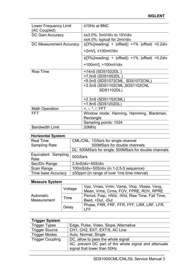
Horizontal System
CML/CNL: 1GSa/s for single channel 500MSa/s for double channels
Real Time Sampling Rate
DL: 500MSa/s for single, 500MSa/s for double channels Equivalent Sampling Rate 50GSa/s
Sec/Div Range 2.5nS/div~50S/div Scan Range 100mS/div~50S/div (in 1-2.5-5 sequence) Time base Accuracy ±50ppm (in range of over 1ms time interval)
Measure System
Voltage Vpp, Vmax, Vmin, Vamp, Vtop, Vbase, Vavg, Mean, Vrms, Crms, FOV, FPRE, ROV, RPRE
Time Period, Frep, +Wid, -Wid, Rise Time, Fall Time, Bwid, +Dut, -Dut
Automatic Measurement
Delay Phase, FRR, FRF, FFR, FFF, LRR, LRF, LFR, LFF
Lower Frequency Limit (AC Coupled)
≤10Hz at BNC
DC Gain Accuracy ≤±3.0%: 5mV/div to 10V/div ≤±4.0%: typical for 2mV/div ±[3%(|reading| + |offset|) +1% |offset| +0.2div
+2mV], ≤100mV/div
DC Measurement Accuracy
±[3%(|reading| + |offset|) +1% |offset| +0.2div
+100mV], >100mV/div
<14nS (SDS1022DL ) <7.0nS (SDS1052DL ) <5.0nS (SDS1072CML, SDS1072CNL) <3.5nS (SDS1102CML,SDS1102CNL
SDS1102DL) <2.3nS (SDS1152CML)
Rise Time
<1.8nS (SDS1202DL) Math Operation +, -, *, /, FFT
Window mode: Hanning, Hamming, Blackman, Rectangle
FFT
Sampling points: 1024 Bandwidth Limit 20MHz
Trigger System Trigger Types Edge, Pulse, Video, Slope, Alternative Trigger Source CH1, CH2, EXT, EXT/5, AC Line Trigger Modes Auto, Normal, Single
DC, allow to pass the whole signal Trigger Coupling AC, prevent DC part of the whole signal and attenuate signal that lower than 50Hz
SIGLENT
4 SDS1000CML/CNL/DL Service Manual
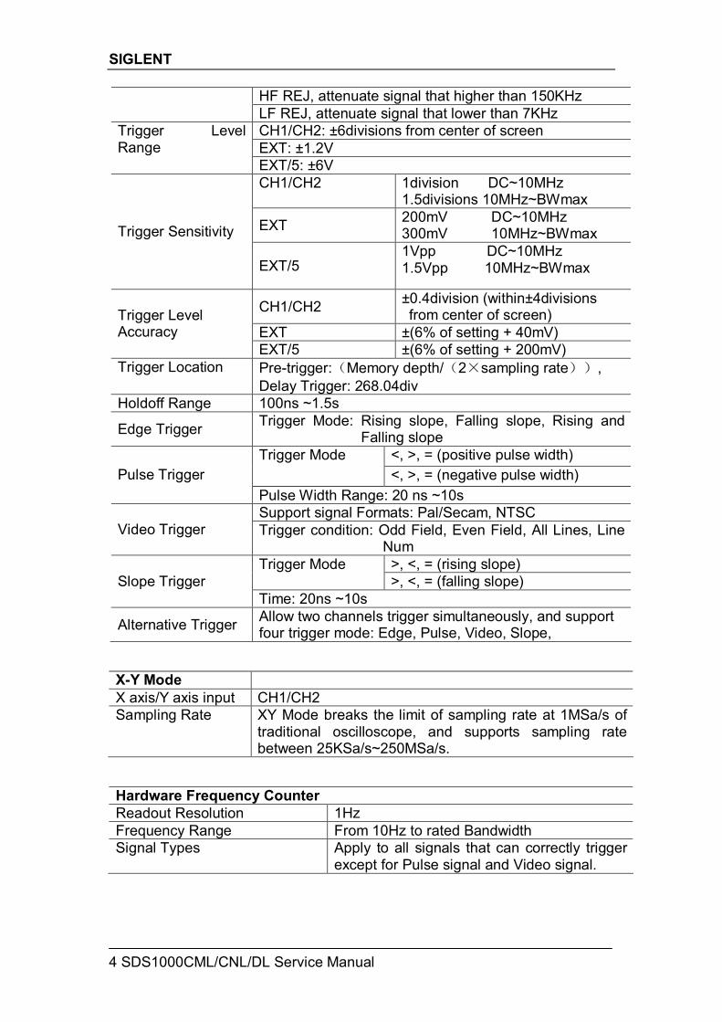
X-Y Mode X axis/Y axis input CH1/CH2 Sampling Rate
XY Mode breaks the limit of sampling rate at 1MSa/s of traditional oscilloscope, and supports sampling rate between 25KSa/s~250MSa/s.
Hardware Frequency Counter Readout Resolution 1Hz Frequency Range From 10Hz to rated Bandwidth Signal Types Apply to all signals that can correctly trigger
except for Pulse signal and Video signal.
HF REJ, attenuate signal that higher than 150KHz LF REJ, attenuate signal that lower than 7KHz CH1/CH2: ±6divisions from center of screen EXT: ±1.2V
Trigger Level Range
EXT/5: ±6V CH1/CH2
1division DC~10MHz 1.5divisions 10MHz~BWmax
EXT 200mV DC~10MHz 300mV 10MHz~BWmax Trigger Sensitivity
EXT/5 1Vpp DC~10MHz 1.5Vpp 10MHz~BWmax
CH1/CH2 ±0.4division (within±4divisions from center of screen)
EXT ±(6% of setting + 40mV) Trigger Level Accuracy
EXT/5 ±(6% of setting + 200mV) Trigger Location Pre-trigger:(Memory depth/(2×sampling rate)),
Delay Trigger: 268.04div Holdoff Range 100ns ~1.5s
Edge Trigger Trigger Mode: Rising slope, Falling slope, Rising and Falling slope
<, >, = (positive pulse width) Trigger Mode <, >, = (negative pulse width) Pulse Trigger
Pulse Width Range: 20 ns ~10s Support signal Formats: Pal/Secam, NTSC
Video Trigger Trigger condition: Odd Field, Even Field, All Lines, Line Num
>, <, = (rising slope) Trigger Mode >, <, = (falling slope) Slope Trigger
Time: 20ns ~10s
Alternative Trigger Allow two channels trigger simultaneously, and support four trigger mode: Edge, Pulse, Video, Slope,
SIGLENT
SDS1000CML/CNL/DL Service Manual 5
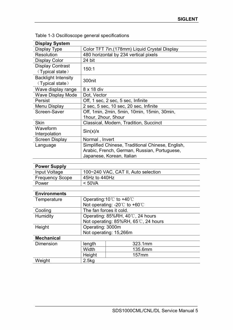
Table 1-3 Oscilloscope general specifications
Display System Display Type Color TFT 7in.(178mm) Liquid Crystal Display Resolution 480 horizontal by 234 vertical pixels Display Color 24 bit Display Contrast (Typical state) 150:1
Backlight Intensity (Typical state) 300nit
Wave display range 8 x 18 div Wave Display Mode Dot, Vector Persist Off, 1 sec, 2 sec, 5 sec, Infinite Menu Display 2 sec, 5 sec, 10 sec, 20 sec, Infinite Screen-Saver Off, 1min, 2min, 5min, 10min, 15min, 30min,
1hour, 2hour, 5hour Skin Classical, Modern, Tradition, Succinct Waveform Interpolation Sin(x)/x
Screen Display Normal , Invert Language Simplified Chinese, Traditional Chinese, English,
Arabic, French, German, Russian, Portuguese, Japanese, Korean, Italian
Power Supply Input Voltage 100~240 VAC, CAT II, Auto selection Frequency Scope 45Hz to 440Hz Power < 50VA Environments Temperature Operating:10℃ to +40℃
Not operating: -20℃ to +60℃ Cooling The fan forces it cold. Humidity Operating: 85%RH, 40℃, 24 hours
Not operating: 85%RH, 65℃, 24 hours Height Operating: 3000m
Not operating: 15,266m Mechanical
length 323.1mm Width 135.6mm
Dimension
Height 157mm Weight 2.5kg
SIGLENT
6 SDS1000CML/CNL/DL Service Manual
Prepare Information Before doing performance verifying or procedure adjusting, you should master the following operations to make the oscilloscope work in a good state or deal with some simple functional problems. This chapter includes the following contents: How to perform functional checks
How to operate four standard interface tests
How to use self-calibration routine
How to recall factory Default settings Fore more detailed information about oscilloscope operation, please refer to you Quick Guide.
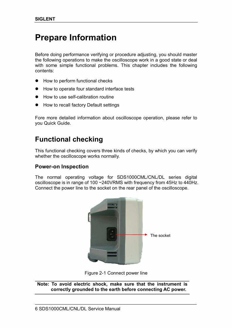
Functional checking This functional checking covers three kinds of checks, by which you can verify whether the oscilloscope works normally. Power-on Inspection The normal operating voltage for SDS1000CML/CNL/DL series digital oscilloscope is in range of 100 ~240VRMS with frequency from 45Hz to 440Hz. Connect the power line to the socket on the rear panel of the oscilloscope.
Figure 2-1 Connect power line Note: To avoid electric shock, make sure that the instrument is
correctly grounded to the earth before connecting AC power.
The socket
SIGLENT
SDS1000CML/CNL/DL Service Manual 7
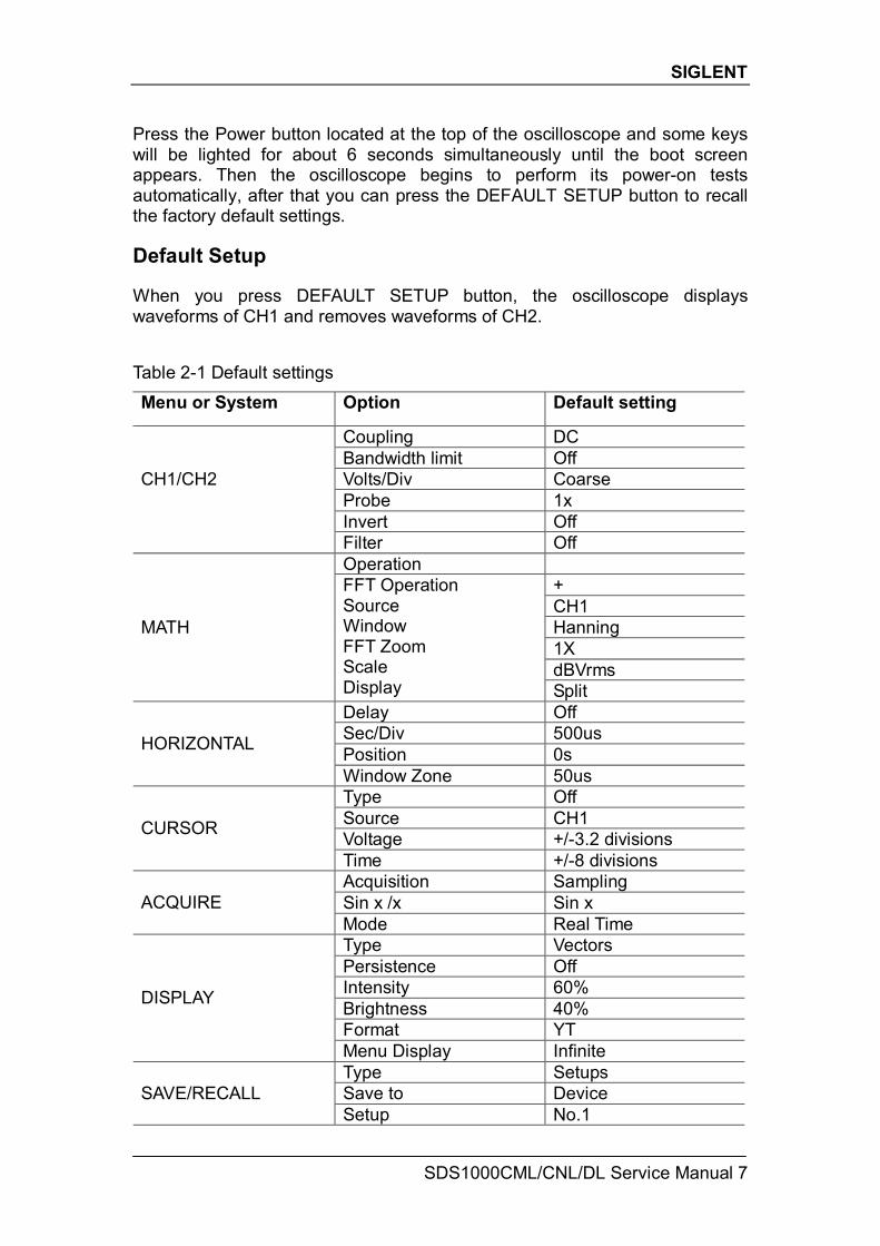
Press the Power button located at the top of the oscilloscope and some keys will be lighted for about 6 seconds simultaneously until the boot screen appears. Then the oscilloscope begins to perform its power-on tests automatically, after that you can press the DEFAULT SETUP button to recall the factory default settings. Default Setup When you press DEFAULT SETUP button, the oscilloscope displays waveforms of CH1 and removes waveforms of CH2. Table 2-1 Default settings
Menu or System Option Default setting
Coupling DC Bandwidth limit Off Volts/Div Coarse Probe 1x Invert Off
CH1/CH2
Filter Off Operation
+ CH1 Hanning 1X dBVrms
MATH
FFT Operation Source Window FFT Zoom Scale Display Split Delay Off Sec/Div 500us Position 0s HORIZONTAL
Window Zone 50us Type Off Source CH1 Voltage +/-3.2 divisions CURSOR
Time +/-8 divisions Acquisition Sampling Sin x /x Sin x ACQUIRE Mode Real Time Type Vectors Persistence Off Intensity 60% Brightness 40% Format YT
DISPLAY
Menu Display Infinite Type Setups Save to Device SAVE/RECALL Setup No.1
SIGLENT
8 SDS1000CML/CNL/DL Service Manual
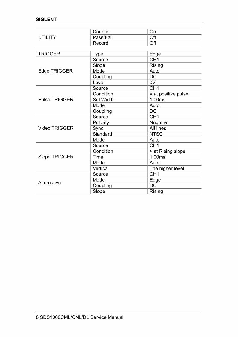
Counter On Pass/Fail Off UTILITY Record Off
TRIGGER Type Edge
Source CH1 Slope Rising Mode Auto Coupling DC
Edge TRIGGER
Level 0V Source CH1 Condition = at positive pulse Set Width 1.00ms Mode Auto
Pulse TRIGGER
Coupling DC Source CH1 Polarity Negative Sync All lines Standard NTSC
Video TRIGGER
Mode Auto Source CH1 Condition > at Rising slope Time 1.00ms Mode Auto
Slope TRIGGER
Vertical The higher level Source CH1 Mode Edge Coupling DC Alternative
Slope Rising
SIGLENT
SDS1000CML/CNL/DL Service Manual 9
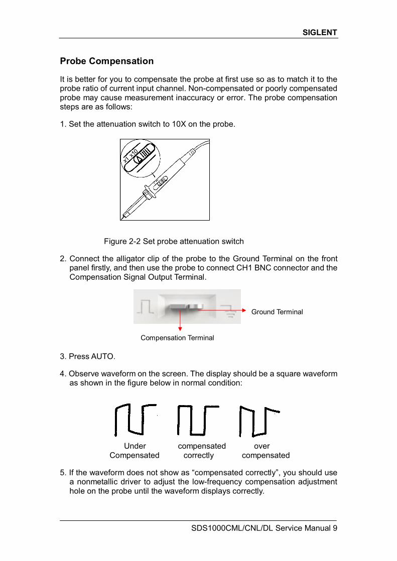
Probe Compensation It is better for you to compensate the probe at first use so as to match it to the probe ratio of current input channel. Non-compensated or poorly compensated probe may cause measurement inaccuracy or error. The probe compensation steps are as follows: 1. Set the attenuation switch to 10X on the probe.
Figure 2-2 Set probe attenuation switch
2. Connect the alligator clip of the probe to the Ground Terminal on the front
panel firstly, and then use the probe to connect CH1 BNC connector and the Compensation Signal Output Terminal.
3. Press AUTO. 4. Observe waveform on the screen. The display should be a square waveform
as shown in the figure below in normal condition:
Under compensated over Compensated correctly compensated
5. If the waveform does not show as “compensated correctly”, you should use
a nonmetallic driver to adjust the low-frequency compensation adjustment hole on the probe until the waveform displays correctly.
Ground Terminal
Compensation Terminal
SIGLENT
10 SDS1000CML/CNL/DL Service Manual
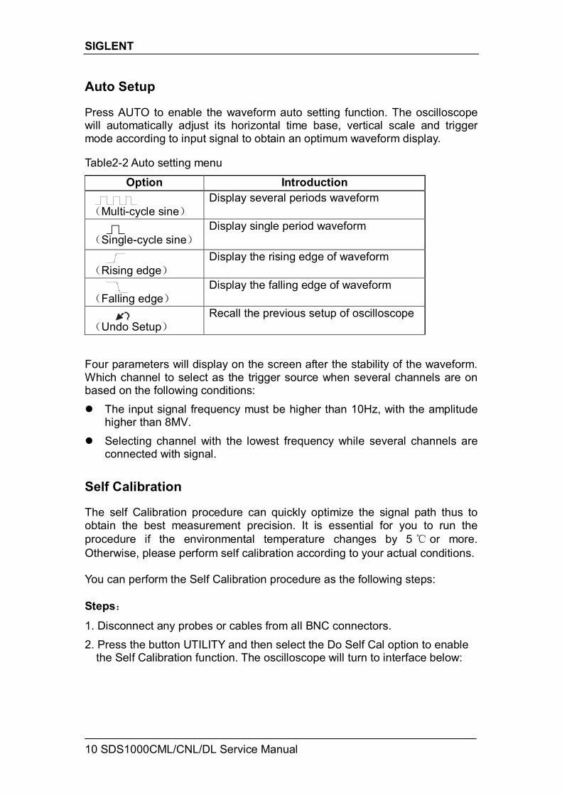
Auto Setup Press AUTO to enable the waveform auto setting function. The oscilloscope will automatically adjust its horizontal time base, vertical scale and trigger mode according to input signal to obtain an optimum waveform display. Table2-2 Auto setting menu
Option Introduction (Multi-cycle sine)
Display several periods waveform
(Single-cycle sine)
Display single period waveform
(Rising edge)
Display the rising edge of waveform
(Falling edge)
Display the falling edge of waveform
(Undo Setup)
Recall the previous setup of oscilloscope
Four parameters will display on the screen after the stability of the waveform. Which channel to select as the trigger source when several channels are on based on the following conditions: The input signal frequency must be higher than 10Hz, with the amplitude
higher than 8MV. Selecting channel with the lowest frequency while several channels are
connected with signal. Self Calibration The self Calibration procedure can quickly optimize the signal path thus to obtain the best measurement precision. It is essential for you to run the procedure if the environmental temperature changes by 5 ℃ or more. Otherwise, please perform self calibration according to your actual conditions. You can perform the Self Calibration procedure as the following steps: Steps:
1. Disconnect any probes or cables from all BNC connectors. 2. Press the button UTILITY and then select the Do Self Cal option to enable
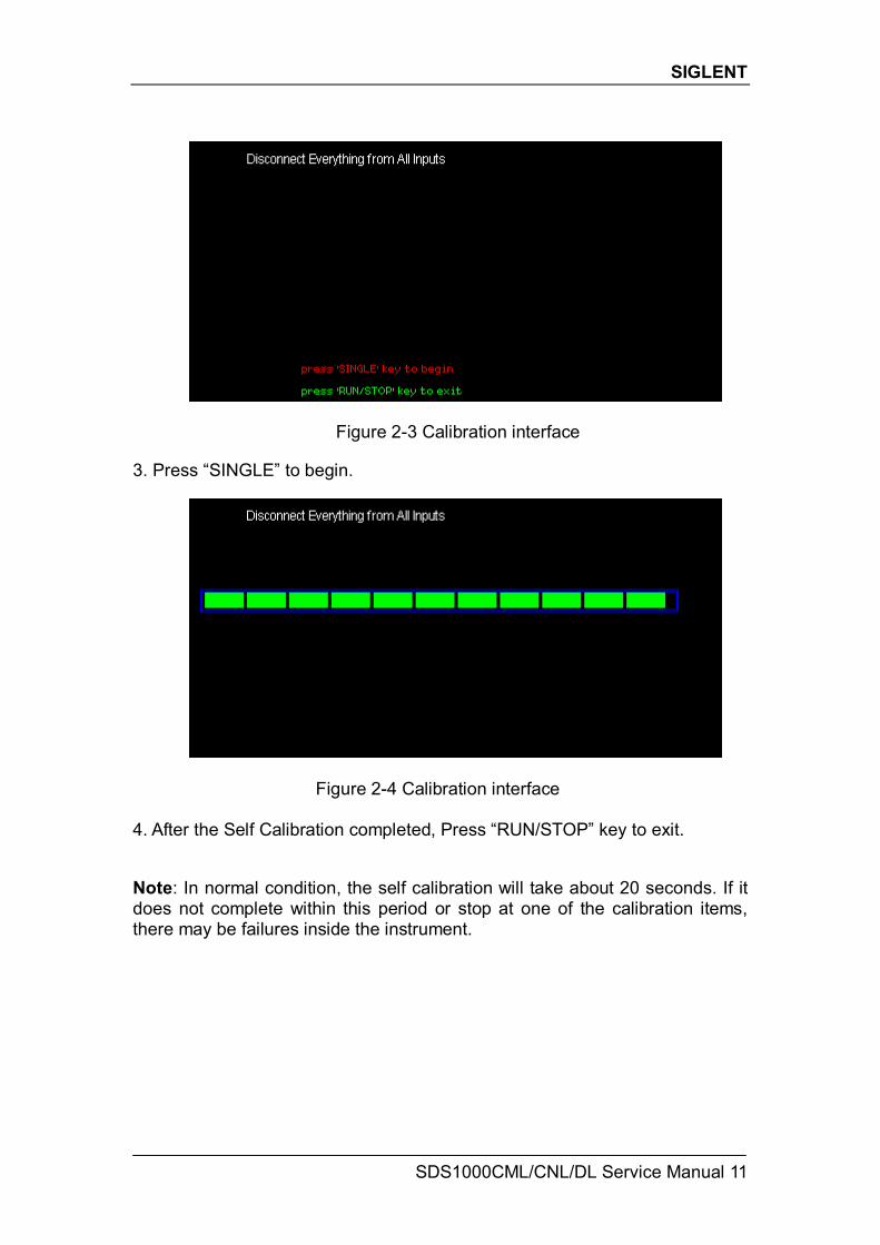
the Self Calibration function. The oscilloscope will turn to interface below:
SIGLENT
SDS1000CML/CNL/DL Service Manual 11
Figure 2-3 Calibration interface
3. Press “SINGLE” to begin.
Figure 2-4 Calibration interface
4. After the Self Calibration completed, Press “RUN/STOP” key to exit.
Note: In normal condition, the self calibration will take about 20 seconds. If it does not complete within this period or stop at one of the calibration items, there may be failures inside the instrument.
SIGLENT
12 SDS1000CML/CNL/DL Service Manual
Interface Test The SDS1000CML/CNL/DL oscilloscope is designed with four standard interfaces: USB Host interface on the front panel, USB Device interface, RS-232 interface and Pass/Fail interface on the rear panel. Being connected to other instruments via these interfaces enables the oscilloscope to realize some advanced functions. To make sure the oscilloscope can work normally, please test the interfaces at first. USB Host Test To test if the USB Host interface works normally.
Tools:
● An SDS1000CML/CNL/DL digital oscilloscope
● An U disk Steps:
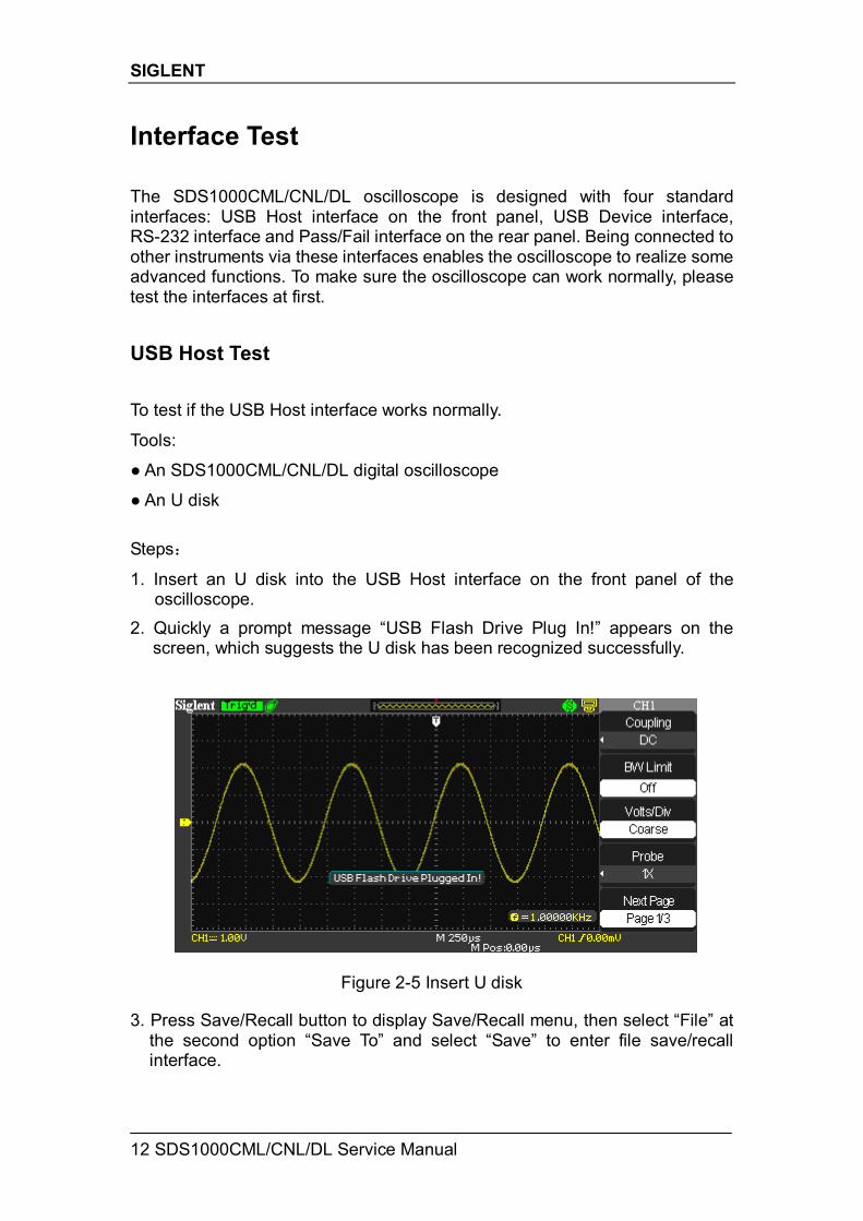
1. Insert an U disk into the USB Host interface on the front panel of the oscilloscope.
2. Quickly a prompt message “USB Flash Drive Plug In!” appears on the screen, which suggests the U disk has been recognized successfully.
Figure 2-5 Insert U disk 3. Press Save/Recall button to display Save/Recall menu, then select “File” at
the second option “Save To” and select “Save” to enter file save/recall interface.
SIGLENT
SDS1000CML/CNL/DL Service Manual 13
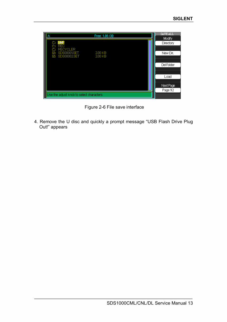
Figure 2-6 File save interface 4. Remove the U disc and quickly a prompt message “USB Flash Drive Plug
Out!” appears
SIGLENT
14 SDS1000CML/CNL/DL Service Manual
USB Device Test To test if the USB Device interface works normally connected with EasyScope software. Tools:
● A SDS1000CML/CNL/DL oscilloscope
● A computer with USB interface
● A standard USB cable (Type AB)
● EasyScopeX software for SDS1000CML/CNL/DL Steps:
1. Set up EasyScopeX software in a computer and Install the driver step by step following the instructions.
2. Connect the oscilloscope and the computer using an USB cable, then select “USBTMC” in “Back USB” menu under the UTILITY menu.
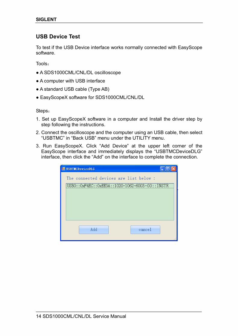
3. Run EasyScopeX. Click “Add Device” at the upper left corner of the EasyScope interface and immediately displays the “USBTMCDeviceDLG” interface, then click the “Add” on the interface to complete the connection.
SIGLENT
SDS1000CML/CNL/DL Service Manual 15
RS-232 Test To test if the RS-232 interface works normally through Super Terminal. Tools: ● An SDS1000CML/CNL/DL Oscilloscope
● A computer with RS-232 interface
● A standard RS-232 cable
Steps:
1. Super Terminal is a type of software within Windows XP itself. Firstly you should set up a Super Terminal shortcut on your desktop. Remember to set the Baud Rate to 38400 during the setup procedures.
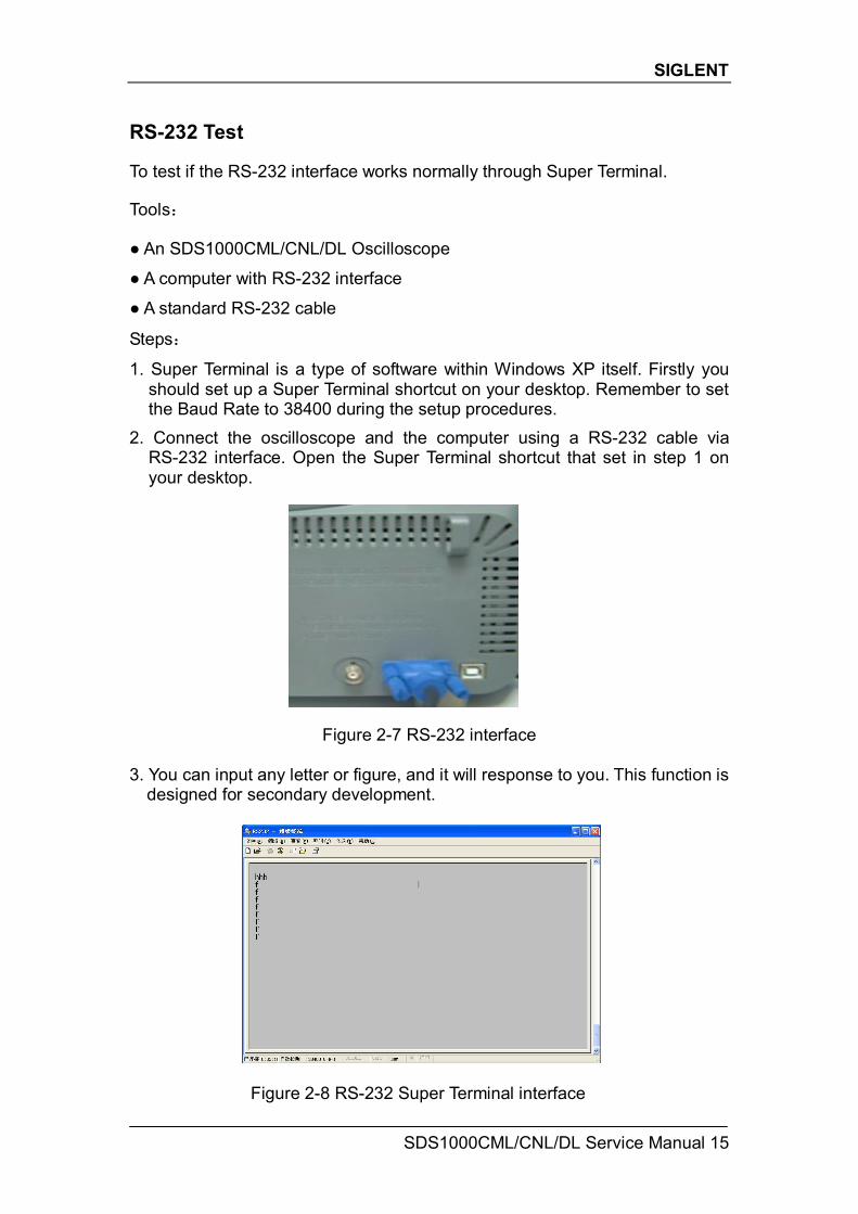
2. Connect the oscilloscope and the computer using a RS-232 cable via RS-232 interface. Open the Super Terminal shortcut that set in step 1 on your desktop.
Figure 2-7 RS-232 interface 3. You can input any letter or figure, and it will response to you. This function is
designed for secondary development.
Figure 2-8 RS-232 Super Terminal interface
SIGLENT
16 SDS1000CML/CNL/DL Service Manual
Pass/Fail Test To test if the Pass/Fail interface works normally connected with another oscilloscope. Tools:
A SDS1000CML/CNL/DL Oscilloscope
An oscilloscope of any type
Two BNC cables
An arbitrary Waveform Generator Steps:
1. Turn on the SDS1000CML/CNL/DL oscilloscope. 2. Input 1 KHz Sine signal to the oscilloscope using an arbitrary Waveform
Generator through a BNC cable, then press AUTO on the front panel of the oscilloscope.
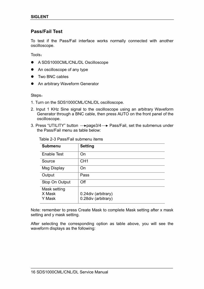
3. Press “UTILITY” button page3/4 Pass/Fail, set the submenus under the Pass/Fail menu as table below:
Table 2-3 Pass/Fail submenu items
Submenu Setting
Enable Test On
Source CH1
Msg Display On
Output Pass
Stop On Output Off
Mask setting X Mask Y Mask
0.24div (arbitrary) 0.28div (arbitrary)
Note: remember to press Create Mask to complete Mask setting after x mask setting and y mask setting. After selecting the corresponding option as table above, you will see the waveform displays as the following:
SIGLENT
SDS1000CML/CNL/DL Service Manual 17
Figure 2-9 Pass/Fail Waveform
If the waveform is in the range that set under menu of Mask setting, it is allowed to pass. Otherwise, it fails to pass.
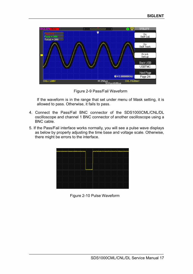
4. Connect the Pass/Fail BNC connector of the SDS1000CML/CNL/DL
oscilloscope and channel 1 BNC connector of another oscilloscope using a BNC cable.
5. If the Pass/Fail interface works normally, you will see a pulse wave displays as below by properly adjusting the time base and voltage scale. Otherwise, there might be errors to the interface.
Figure 2-10 Pulse Waveform
SIGLENT
18 SDS1000CML/CNL/DL Service Manual
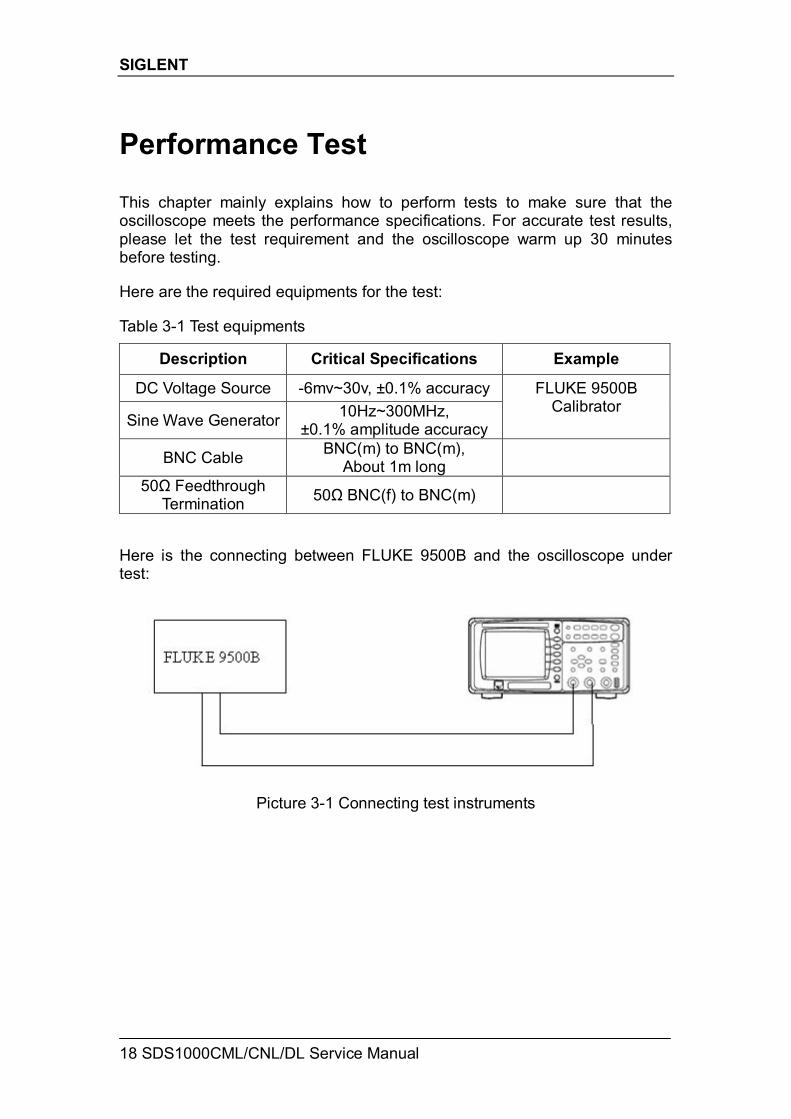
Performance Test This chapter mainly explains how to perform tests to make sure that the oscilloscope meets the performance specifications. For accurate test results, please let the test requirement and the oscilloscope warm up 30 minutes before testing. Here are the required equipments for the test: Table 3-1 Test equipments
Description Critical Specifications Example
DC Voltage Source -6mv~30v, ±0.1% accuracy
Sine Wave Generator 10Hz~300MHz, ±0.1% amplitude accuracy
FLUKE 9500B Calibrator
BNC Cable BNC(m) to BNC(m), About 1m long
50Ω Feedthrough Termination 50Ω BNC(f) to BNC(m)
Here is the connecting between FLUKE 9500B and the oscilloscope under test:
Picture 3-1 Connecting test instruments
SIGLENT
SDS1000CML/CNL/DL Service Manual 19
Verify Test Results To verify whether a test passes, whether the readings are within the limits, it is necessary for you to record the readings in the Performance Test on Test Record. Self Test This internal procedure is automatically performed every time the oscilloscope powers on. No test equipments are required. Verify that no error messages are displayed before continuing with the procedure. Self Calibration You must perform the Self Calibration operation described in chapter 2. If the environmental temperature changes by more than 5℃, you must perform the Self Calibration operation again.
SIGLENT
20 SDS1000CML/CNL/DL Service Manual
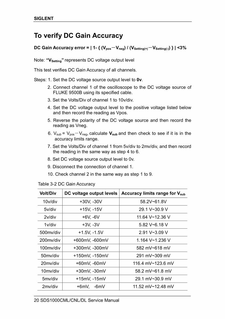
To verify DC Gain Accuracy DC Gain Accuracy error = | 1- { (Vpos-Vneg) / (VSetting(+)-VSetting(-)) } | <3% Note: “VSetting” represents DC voltage output level This test verifies DC Gain Accuracy of all channels. Steps: 1. Set the DC voltage source output level to 0v. 2. Connect channel 1 of the oscilloscope to the DC voltage source of
FLUKE 9500B using its specified cable. 3. Set the Volts/Div of channel 1 to 10v/div. 4. Set the DC voltage output level to the positive voltage listed below
and then record the reading as Vpos. 5. Reverse the polarity of the DC voltage source and then record the
reading as Vneg.
6. Vsub = Vpos-Vneg, calculate Vsub and then check to see if it is in the accuracy limits range.
7. Set the Volts/Div of channel 1 from 5v/div to 2mv/div, and then record the reading in the same way as step 4 to 6.
8. Set DC voltage source output level to 0v. 9. Disconnect the connection of channel 1. 10. Check channel 2 in the same way as step 1 to 9.
Table 3-2 DC Gain Accuracy
Volt/Div DC voltage output levels Accuracy limits range for Vsub
10v/div +30V, -30V 58.2V~61.8V
5v/div +15V, -15V 29.1 V~30.9 V
2v/div +6V, -6V 11.64 V~12.36 V
1v/div +3V, -3V 5.82 V~6.18 V
500mv/div +1.5V, -1.5V 2.91 V~3.09 V
200mv/div +600mV, -600mV 1.164 V~1.236 V
100mv/div +300mV, -300mV 582 mV~618 mV
50mv/div +150mV, -150mV 291 mV~309 mV
20mv/div +60mV, -60mV 116.4 mV~123.6 mV
10mv/div +30mV, -30mV 58.2 mV~61.8 mV
5mv/div +15mV, -15mV 29.1 mV~30.9 mV
2mv/div +6mV, -6mV 11.52 mV~12.48 mV
SIGLENT
SDS1000CML/CNL/DL Service Manual 21
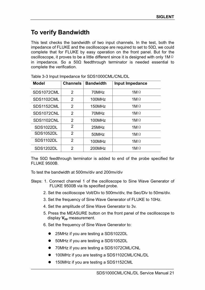
To verify Bandwidth This test checks the bandwidth of two input channels. In the test, both the impedance of FLUKE and the oscilloscope are required to set to 50Ω, we could complete that for FLUKE by easy operation on the front panel. But for the oscilloscope, it proves to be a little different since it is designed with only 1MΩ in impedance. So a 50Ω feedthrough terminator is needed essential to complete the verification. Table 3-3 Input Impedance for SDS1000CML/CNL/DL Model Channels Bandwidth Input Impedance
SDS1072CML 2 70MHz 1MΩ
SDS1102CML 2 100MHz 1MΩ
SDS1152CML 2 150MHz 1MΩ
SDS1072CNL 2 70MHz 1MΩ
SDS1102CNL 2 100MHz 1MΩ
SDS1022DL 2 25MHz 1MΩ SDS1052DL 2 50MHz 1MΩ SDS1102DL 2 100MHz 1MΩ
SDS1202DL 2 200MHz 1MΩ The 50Ω feedthrough terminator is added to end of the probe specified for FLUKE 9500B. To test the bandwidth at 500mv/div and 200mv/div Steps: 1. Connect channel 1 of the oscilloscope to Sine Wave Generator of
FLUKE 9500B via its specified probe. 2. Set the oscilloscope Volt/Div to 500mv/div, the Sec/Div to 50ms/div. 3. Set the frequency of Sine Wave Generator of FLUKE to 10Hz. 4. Set the amplitude of Sine Wave Generator to 3v. 5. Press the MEASURE button on the front panel of the oscilloscope to
display Vpp measurement. 6. Set the frequency of Sine Wave Generator to:
25MHz if you are testing a SDS1022DL
50MHz if you are testing a SDS1052DL
70MHz if you are testing a SDS1072CML/CNL
100MHz if you are testing a SDS1102CML/CNL/DL
150MHz if you are testing a SDS1152CML
SIGLENT
22 SDS1000CML/CNL/DL Service Manual
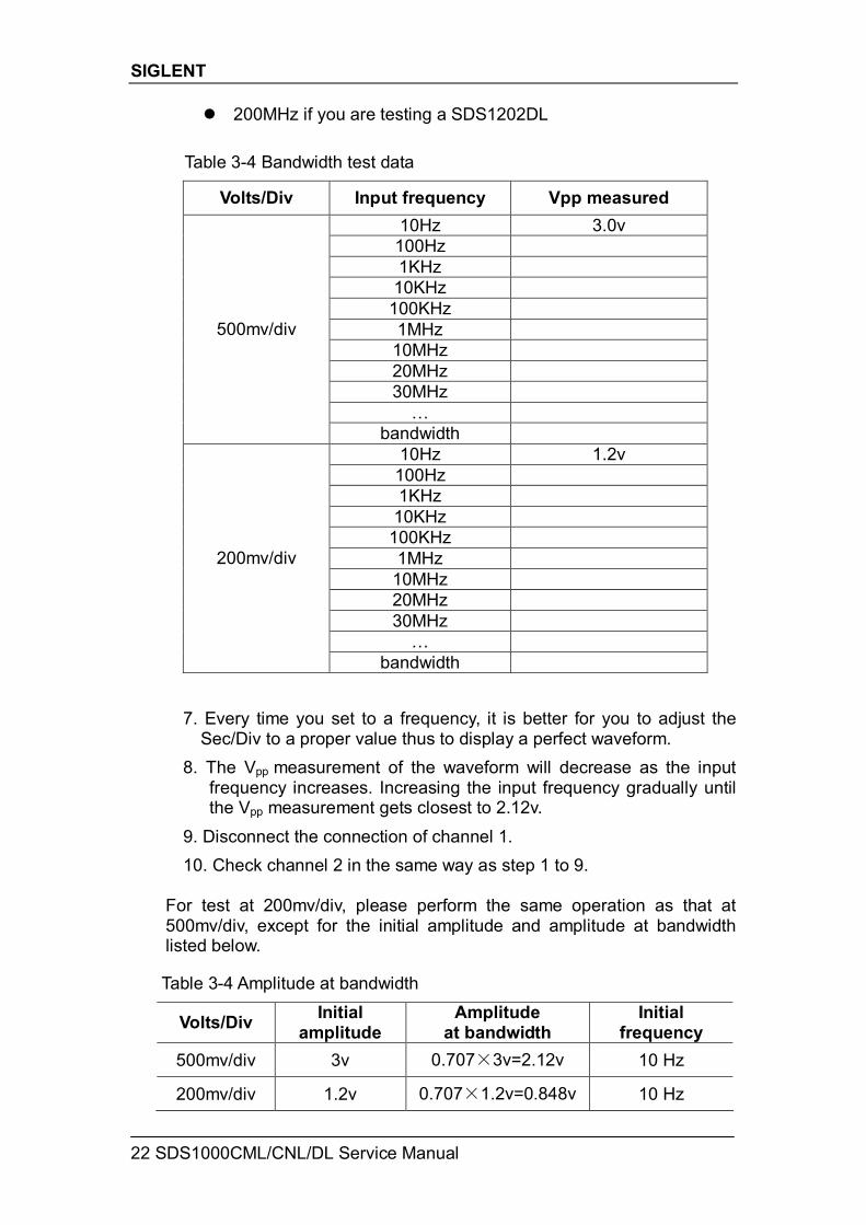
200MHz if you are testing a SDS1202DL Table 3-4 Bandwidth test data
Volts/Div Input frequency Vpp measured 10Hz 3.0v
100Hz 1KHz
10KHz 100KHz 1MHz
10MHz 20MHz 30MHz
…
500mv/div
bandwidth 10Hz 1.2v
100Hz 1KHz
10KHz 100KHz 1MHz
10MHz 20MHz 30MHz
…
200mv/div
bandwidth 7. Every time you set to a frequency, it is better for you to adjust the
Sec/Div to a proper value thus to display a perfect waveform. 8. The Vpp measurement of the waveform will decrease as the input
frequency increases. Increasing the input frequency gradually until the Vpp measurement gets closest to 2.12v.
9. Disconnect the connection of channel 1. 10. Check channel 2 in the same way as step 1 to 9.
For test at 200mv/div, please perform the same operation as that at 500mv/div, except for the initial amplitude and amplitude at bandwidth listed below.
Table 3-4 Amplitude at bandwidth
Volts/Div Initial amplitude
Amplitude at bandwidth
Initial frequency
500mv/div 3v 0.707×3v=2.12v 10 Hz
200mv/div 1.2v 0.707×1.2v=0.848v 10 Hz
SIGLENT
SDS1000CML/CNL/DL Service Manual 23
To verify Time Base Accuracy This test checks the time base accuracy of one channel. In the test, both the impedance of FLUKE and the oscilloscope are required to set to 50Ω. It is convenient for FLUKE by easy operation on the front panel. But for SDS1000L oscilloscope, you need to add a 50Ω feedthrough terminator at the end of spec head of FLUKE. Time Base Accuracy: Freq/10M < 50ppm Steps: 1. Connect selected channel of the oscilloscope to the Sine Wave
Generator of FLUKE 9500B. 2. Set the frequency of the Sine Wave Generator to 10MHz. 3. Set the oscilloscope Volts/Div to 500mv/div. 4. Set the oscilloscope Sec/Div to 1ms/div. 5. Press MEASURE button on the front panel of the oscilloscope to
display Freq measurement. 6. Calculate Freq/10M to see if the value is within the range of 50ppm,
which means correct time base accuracy. 7. Disconnect the test connection.
SIGLENT
24 SDS1000CML/CNL/DL Service Manual
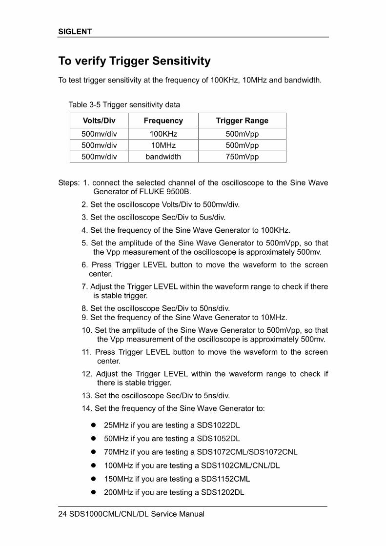
To verify Trigger Sensitivity To test trigger sensitivity at the frequency of 100KHz, 10MHz and bandwidth. Table 3-5 Trigger sensitivity data
Volts/Div Frequency Trigger Range
500mv/div 100KHz 500mVpp 500mv/div 10MHz 500mVpp 500mv/div bandwidth 750mVpp
Steps: 1. connect the selected channel of the oscilloscope to the Sine Wave
Generator of FLUKE 9500B. 2. Set the oscilloscope Volts/Div to 500mv/div. 3. Set the oscilloscope Sec/Div to 5us/div. 4. Set the frequency of the Sine Wave Generator to 100KHz. 5. Set the amplitude of the Sine Wave Generator to 500mVpp, so that
the Vpp measurement of the oscilloscope is approximately 500mv. 6. Press Trigger LEVEL button to move the waveform to the screen
center. 7. Adjust the Trigger LEVEL within the waveform range to check if there
is stable trigger. 8. Set the oscilloscope Sec/Div to 50ns/div. 9. Set the frequency of the Sine Wave Generator to 10MHz. 10. Set the amplitude of the Sine Wave Generator to 500mVpp, so that
the Vpp measurement of the oscilloscope is approximately 500mv. 11. Press Trigger LEVEL button to move the waveform to the screen
center. 12. Adjust the Trigger LEVEL within the waveform range to check if
there is stable trigger. 13. Set the oscilloscope Sec/Div to 5ns/div. 14. Set the frequency of the Sine Wave Generator to:
25MHz if you are testing a SDS1022DL
50MHz if you are testing a SDS1052DL
70MHz if you are testing a SDS1072CML/SDS1072CNL
100MHz if you are testing a SDS1102CML/CNL/DL
150MHz if you are testing a SDS1152CML
200MHz if you are testing a SDS1202DL
SIGLENT
SDS1000CML/CNL/DL Service Manual 25
15. Set the amplitude of the Sine Wave Generator to 750mVpp, so that the Vpp measurement of the oscilloscope is approximately 750mv.
16. Press Trigger LEVEL button to move the waveform to the screen center.
17. Adjust the Trigger LEVEL within the waveform range to check if there is stable trigger.
18. Disconnect the test connection. 19. Check CH1 in the same way as step 1 to 18.
SIGLENT
26 SDS1000CML/CNL/DL Service Manual
Adjusting Procedures This chapter explains how to adjust the SDS1000CML/CNL/DL series oscilloscope with FLUKE 9500B for optimum operating performance. Only qualified personnel should perform this procedure. Warming up Before performing the adjustment procedures, you must let the oscilloscope and other test equipments warm up for at least 30 minutes in an ambient temperature between 20 °C and 30 °C. Adjustments performed prior to warm-up or outside this temperature range may result in poor performance. Self calibration The Self-Cal performs an internal routine which uses internally generated signals to optimize circuits that affect channel sensitivity, offset, and trigger parameters, to optimize the signal path in the oscilloscope. Let the oscilloscope warm up before performing this procedure. Required Equipments PC: Inter Pentium processor, Windows XP operating system, USB interface,
Microsoft Office Excel 2003, NI-GPIB Card and corresponding NI-488.2 driver
Calibrating Software: EasyTest, Adjustment script Test Instrument: FLUKE 9500B with active head An USB cable (Type AB) A GPIB cable Two 10-inch BNC cables A BNC T connector Software Installation 1. Install the NI-488.2 driver, select custom installation to install NI-VISA. 2. Install the EasyTest software. 3. Decompress production. zip file to E disk directory. Adjusting steps 1. Connect the FLUKE 9500B with PC using a GPIB cable. 2. Connect the oscilloscope with PC using an USB cable.
SIGLENT
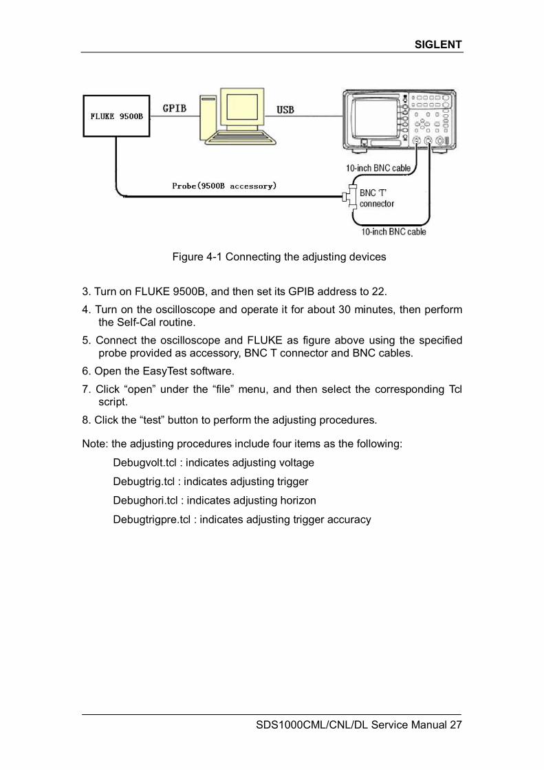
SDS1000CML/CNL/DL Service Manual 27
Figure 4-1 Connecting the adjusting devices 3. Turn on FLUKE 9500B, and then set its GPIB address to 22. 4. Turn on the oscilloscope and operate it for about 30 minutes, then perform
the Self-Cal routine. 5. Connect the oscilloscope and FLUKE as figure above using the specified
probe provided as accessory, BNC T connector and BNC cables. 6. Open the EasyTest software. 7. Click “open” under the “file” menu, and then select the corresponding Tcl
script. 8. Click the “test” button to perform the adjusting procedures. Note: the adjusting procedures include four items as the following:
Debugvolt.tcl : indicates adjusting voltage
Debugtrig.tcl : indicates adjusting trigger
Debughori.tcl : indicates adjusting horizon
Debugtrigpre.tcl : indicates adjusting trigger accuracy
SIGLENT
28 SDS1000CML/CNL/DL Service Manual
Assembly Procedures This chapter describes how to remove the major modules from the SDS1000CML/CNL/DL series oscilloscopes. To install the removed modules or replace new modules, please follow corresponding operating steps in reverse order. The following contents are what mainly included in this chapter: Security Consideration which describes security information needed to
considerate while operating. List of Modules in which the modules to remove are listed. Required Tools which describes the tools needed to perform the
procedures. Disassembly Procedures which describes in detail how to remove and
install the modules. Security Consideration Only qualified personnel should perform the disassembly procedures. Whenever possible, disconnect the power before you begin to remove or replace the modules. Otherwise, any personal injuries or damages to the components may occur. Avoid Electric Shock Hazardous voltages exist on the LCD module and power supply module. To avoid electrical shock, you should firstly disconnect the power cord from the oscilloscope, and then wait at least three minutes for the capacitors in the oscilloscope to discharge before you begin disassembly. Preventing ESD Electrostatic discharge (ESD) can damage electronic components. When doing any of the procedures in this chapter, use proper ESD precautions. As a minimum, you should place the oscilloscope on a properly grounded ESD mat and wear a properly grounded ESD strap. List of Modules The following removable modules are listed in the order of performing disassembly procedures.
SIGLENT
SDS1000CML/CNL/DL Service Manual 29
Table 5-1 List of modules Number of Module Module
1 Front-Panel Knobs
2 Rear Panel 3 Rear Metal Cover
4 Top Metal Cover
5 Power Supply Module
6 Metal Shelf
7 Main Board Module
8 Fan Module
9 Display Module
10 Keypad Module Required Tools Use these tools to remove or replace the modules in the oscilloscope: T6, T10 and T20 TORX drivers
5/8- inch and 9/32- inch socket drivers
Flat head screw driver Disassembly Procedures This section describes how to remove and install the modules listed above in the oscilloscope in detail. Complete disassembly will be best achieved through the following operating steps.
SIGLENT
30 SDS1000CML/CNL/DL Service Manual
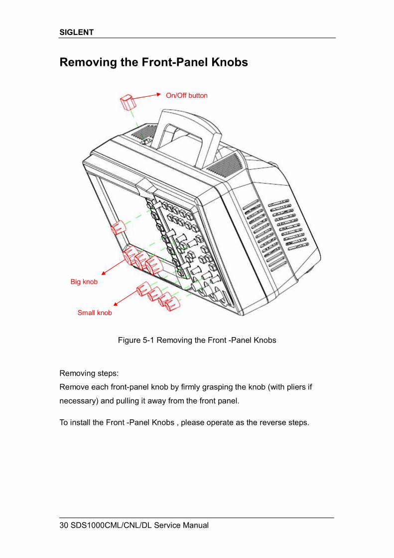
Removing the Front-Panel Knobs
Figure 5-1 Removing the Front -Panel Knobs Removing steps:
Remove each front-panel knob by firmly grasping the knob (with pliers if
necessary) and pulling it away from the front panel. To install the Front -Panel Knobs , please operate as the reverse steps.
Big knob
Small knob
On/Off button
SIGLENT
SDS1000CML/CNL/DL Service Manual 31
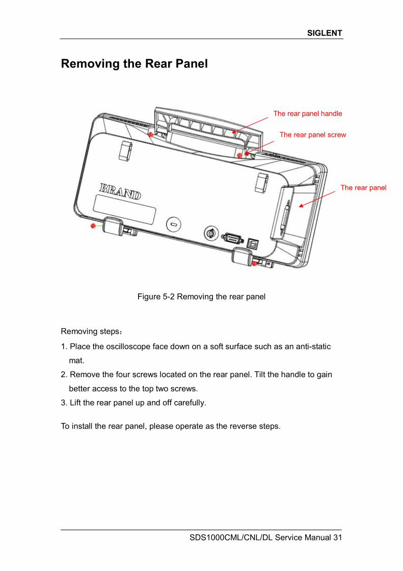
Removing the Rear Panel
Figure 5-2 Removing the rear panel
Removing steps:
1. Place the oscilloscope face down on a soft surface such as an anti-static
mat.
2. Remove the four screws located on the rear panel. Tilt the handle to gain
better access to the top two screws.
3. Lift the rear panel up and off carefully.
To install the rear panel, please operate as the reverse steps.
The rear panel screw
The rear panel handle
The rear panel
SIGLENT
32 SDS1000CML/CNL/DL Service Manual
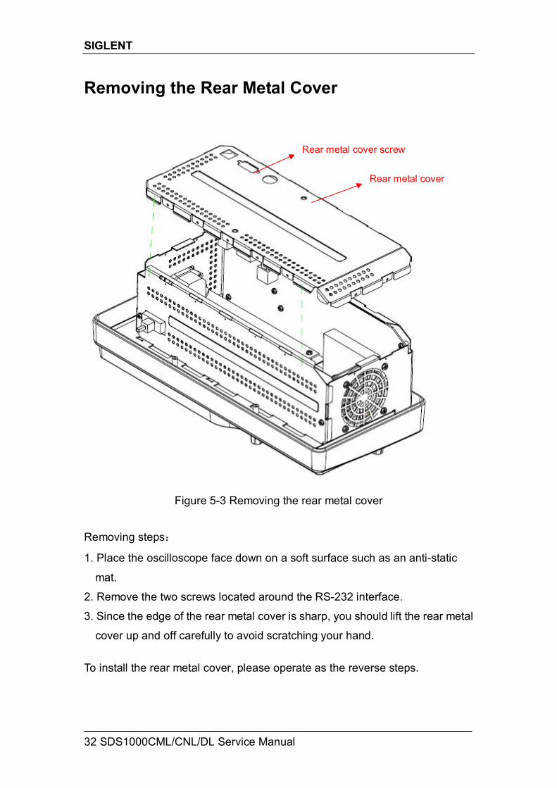
Removing the Rear Metal Cover
Figure 5-3 Removing the rear metal cover Removing steps:
1. Place the oscilloscope face down on a soft surface such as an anti-static
mat.
2. Remove the two screws located around the RS-232 interface.
3. Since the edge of the rear metal cover is sharp, you should lift the rear metal
cover up and off carefully to avoid scratching your hand.
To install the rear metal cover, please operate as the reverse steps.
Rear metal cover
Rear metal cover screw
SIGLENT
SDS1000CML/CNL/DL Service Manual 33
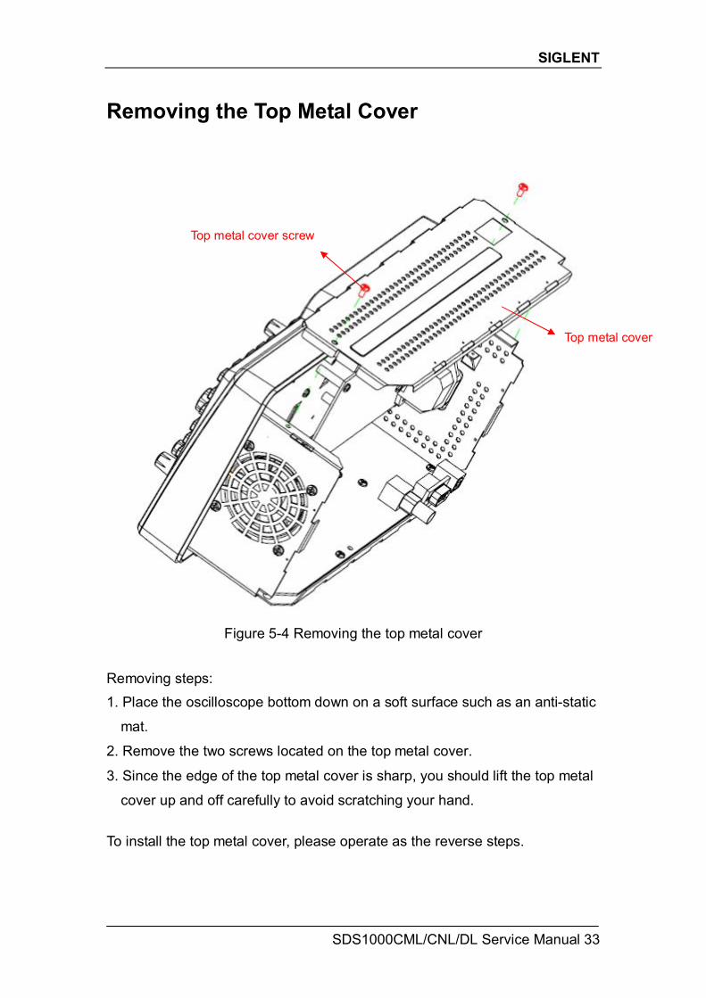
Removing the Top Metal Cover
Figure 5-4 Removing the top metal cover Removing steps: 1. Place the oscilloscope bottom down on a soft surface such as an anti-static
mat.
2. Remove the two screws located on the top metal cover.
3. Since the edge of the top metal cover is sharp, you should lift the top metal
cover up and off carefully to avoid scratching your hand.
To install the top metal cover, please operate as the reverse steps.
Top metal cover
Top metal cover screw
SIGLENT
34 SDS1000CML/CNL/DL Service Manual
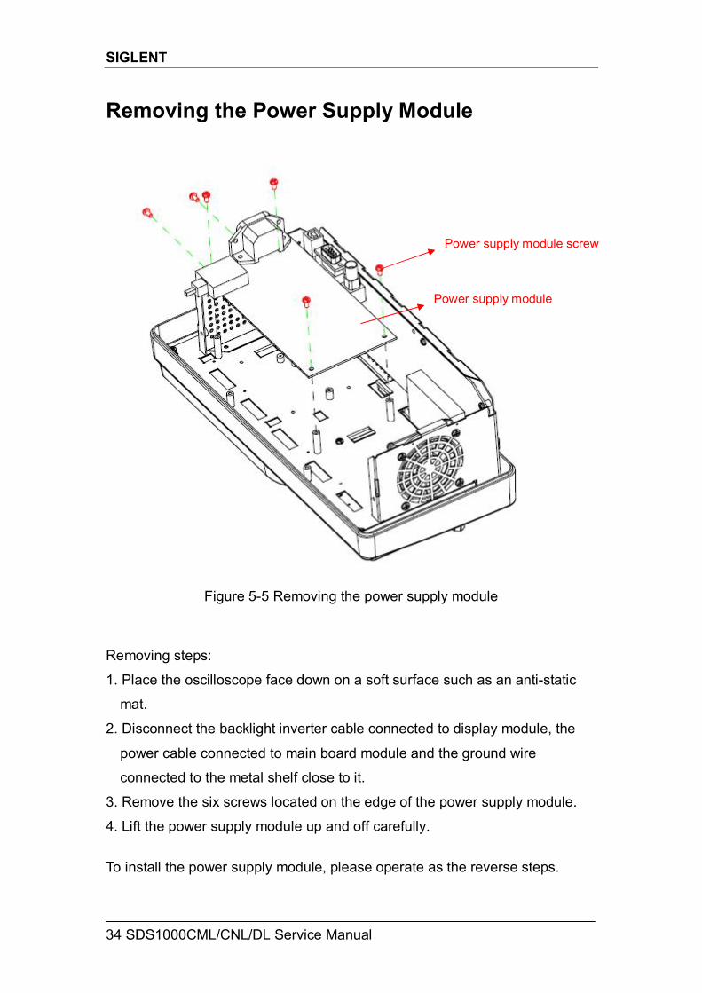
Removing the Power Supply Module
Figure 5-5 Removing the power supply module Removing steps:
1. Place the oscilloscope face down on a soft surface such as an anti-static
mat.
2. Disconnect the backlight inverter cable connected to display module, the
power cable connected to main board module and the ground wire
connected to the metal shelf close to it.
3. Remove the six screws located on the edge of the power supply module.
4. Lift the power supply module up and off carefully.
To install the power supply module, please operate as the reverse steps.
Power supply module
Power supply module screw
SIGLENT
SDS1000CML/CNL/DL Service Manual 35
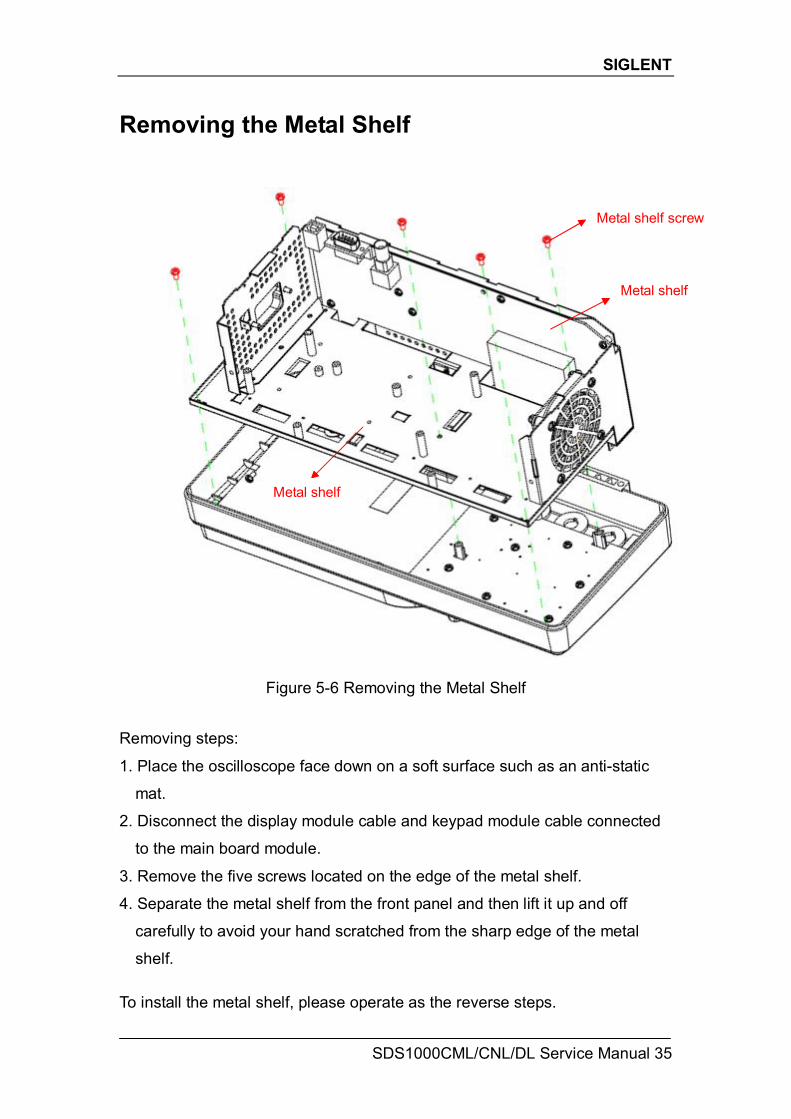
Removing the Metal Shelf
Figure 5-6 Removing the Metal Shelf Removing steps:
1. Place the oscilloscope face down on a soft surface such as an anti-static
mat.
2. Disconnect the display module cable and keypad module cable connected
to the main board module.
3. Remove the five screws located on the edge of the metal shelf.
4. Separate the metal shelf from the front panel and then lift it up and off
carefully to avoid your hand scratched from the sharp edge of the metal
shelf. To install the metal shelf, please operate as the reverse steps.
Metal shelf screw
Metal shelf
Metal shelf
SIGLENT
36 SDS1000CML/CNL/DL Service Manual
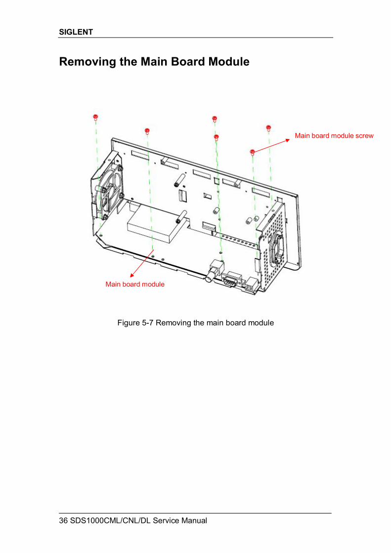
Removing the Main Board Module
Figure 5-7 Removing the main board module
Main board module screw
Main board module
SIGLENT
SDS1000CML/CNL/DL Service Manual 37
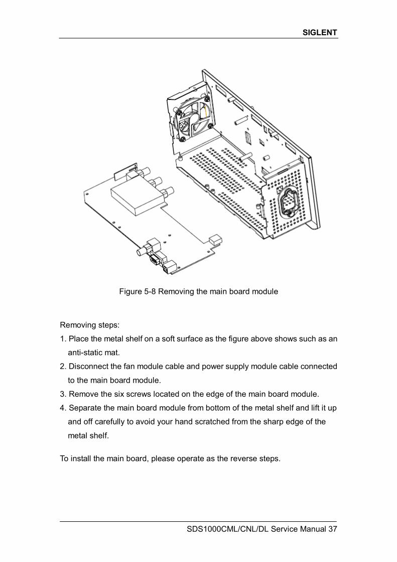
Figure 5-8 Removing the main board module Removing steps:
1. Place the metal shelf on a soft surface as the figure above shows such as an
anti-static mat.
2. Disconnect the fan module cable and power supply module cable connected
to the main board module.
3. Remove the six screws located on the edge of the main board module.
4. Separate the main board module from bottom of the metal shelf and lift it up
and off carefully to avoid your hand scratched from the sharp edge of the
metal shelf.
To install the main board, please operate as the reverse steps.
SIGLENT
38 SDS1000CML/CNL/DL Service Manual
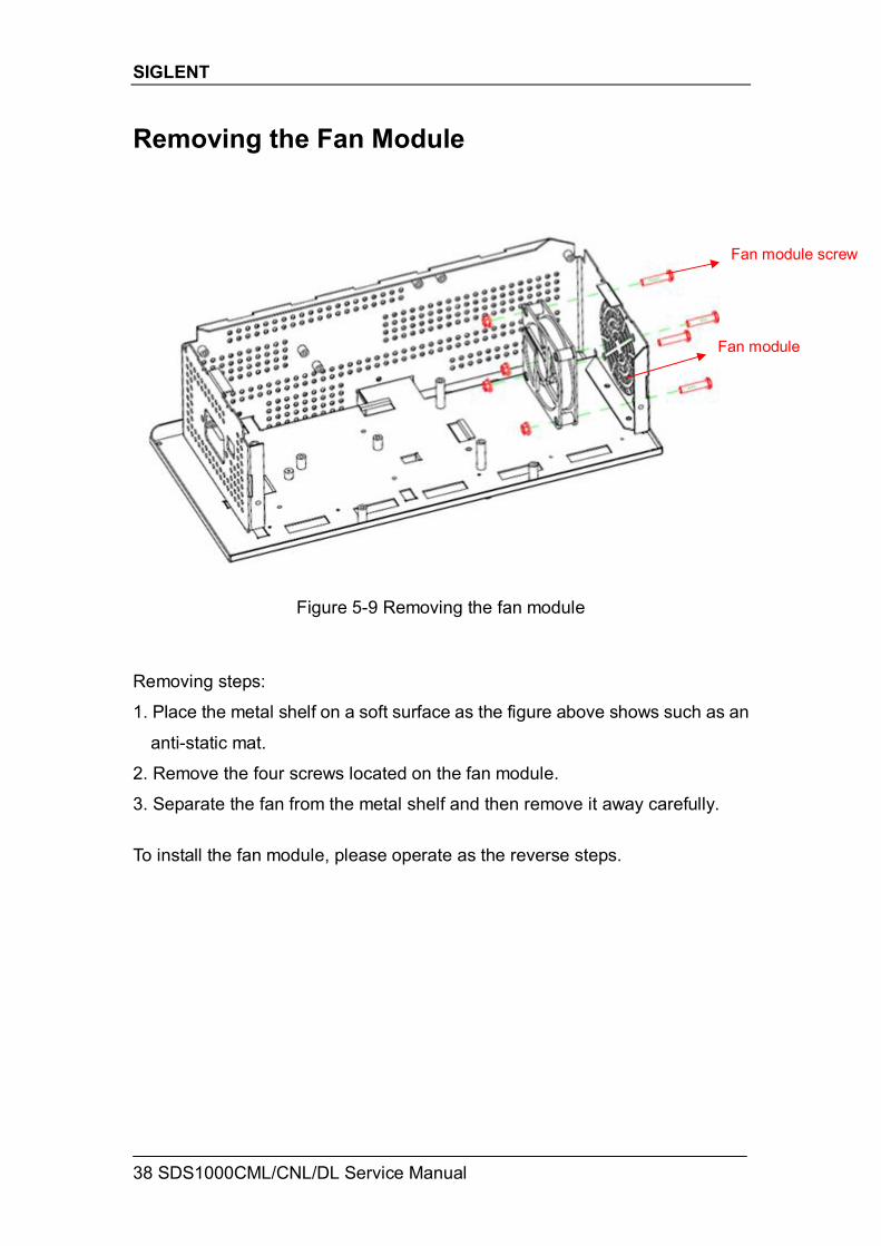
Removing the Fan Module
Figure 5-9 Removing the fan module Removing steps:
1. Place the metal shelf on a soft surface as the figure above shows such as an
anti-static mat.
2. Remove the four screws located on the fan module.
3. Separate the fan from the metal shelf and then remove it away carefully.
To install the fan module, please operate as the reverse steps.
Fan module
Fan module screw
SIGLENT
SDS1000CML/CNL/DL Service Manual 39
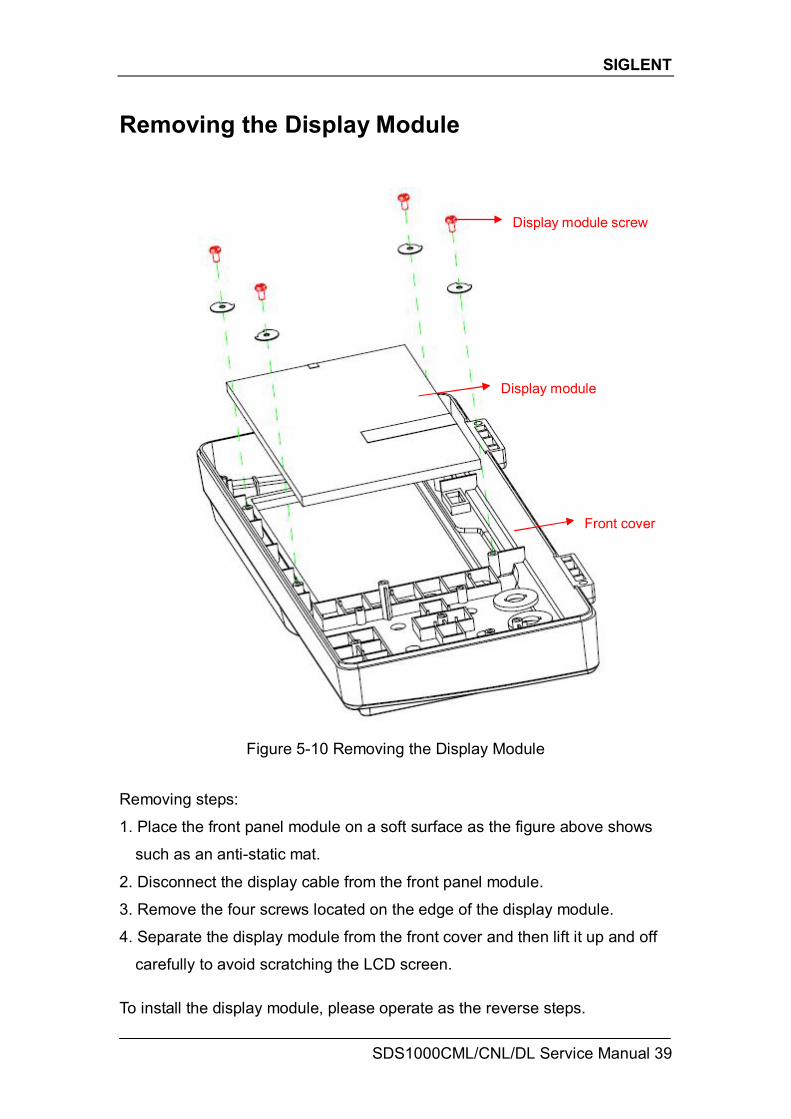
Removing the Display Module
Figure 5-10 Removing the Display Module Removing steps:
1. Place the front panel module on a soft surface as the figure above shows
such as an anti-static mat.
2. Disconnect the display cable from the front panel module.
3. Remove the four screws located on the edge of the display module.
4. Separate the display module from the front cover and then lift it up and off
carefully to avoid scratching the LCD screen. To install the display module, please operate as the reverse steps.
Display module
Display module screw
Front cover
SIGLENT
40 SDS1000CML/CNL/DL Service Manual
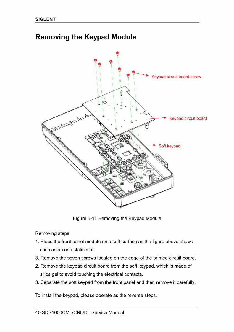
Removing the Keypad Module
Figure 5-11 Removing the Keypad Module Removing steps:
1. Place the front panel module on a soft surface as the figure above shows
such as an anti-static mat.
3. Remove the seven screws located on the edge of the printed circuit board.
2. Remove the keypad circuit board from the soft keypad, which is made of
silica gel to avoid touching the electrical contacts.
3. Separate the soft keypad from the front panel and then remove it carefully. To install the keypad, please operate as the reverse steps.
Keypad circuit board
Soft keypad
Keypad circuit board screw
SIGLENT
SDS1000CML/CNL/DL Service Manual 41
Troubleshooting This chapter explains how to deal with general troubles you may encounter while operating SDS1000CML/CNL/DL series oscilloscope.
General troubles 1. The screen remains dark after power on:
(1) Check if the power cord is correctly connected. (2) Check whether the fuse is burned out. If the fuse needs to be changed,
please contact with SIGLENT as soon as possible and return the instrument to the factory to have it repaired by qualified personnel authorized by SIGLENT.
(3) Restart the instrument after completing inspections above. (4) If it still does not work normally, please refer to the Display
Troubleshooting or contact SIGLENT. 2. After the signal is sampled, there is no corresponding waveform displaying:
(1) Check if the signal connecting cord is correctly connected to BNC connector.
(2) Check if the Intensity knob on the front panel is properly adjusted. (3) Check if the probe is correctly connected to the item under test. (4) Check if there are signal generated from the item under test
(You can connect the probe compensation signal to the problematic channel to determine the reason to the problem)
(5) Resample the signal. 3. The voltage amplitude measured is higher or lower than the actual value
(this error usually occurs in use of probe): (1) Check if the attenuation coefficient of the current channel matches with
the attenuation ratio of the probe. (2) Check if the BW Limit under the menu of CH1/CH2 is on. If it is on, the
amplitude of the waveform is lower than the actual value. 4. There is waveform displaying but not stable:
(1) Check the trigger source: check whether the “Source” in menu of “TRIG” is the actual operating channel.
(2) Check if the waveform is wrong: it is easy for us to regard the wrong waveform as the real when a high frequency signal is connected to the instrument. You’d better make sure that the current time base is correct for the frequency of input signal.
(3) Check the trigger type: “Edge” trigger suits to general signal and “Video” trigger suits to video signal. Only in correct trigger type can the waveform stably display.
(4) Change the setting of trigger holdoff.
SIGLENT
42 SDS1000CML/CNL/DL Service Manual
5. No display after pressing RUN/STOP:
Check whether the trigger Mode is “Normal” or “Single”, and if the trigger level exceeds the waveform range. If yes, set the trigger level to the middle or change the trigger Mode to “Auto”. Note: press AUTO could automatically replace the above setting.
6. The waveform displays like ladder:
(1) The horizontal time base may be too low, you could increase it to improve the horizontal resolution so as to obtain a good waveform displaying.
(2) The lines between the sample points may also cause ladder-like displaying if the “Type” in menu of “DISPLAY” is “Vectors”. Please turn the “Type” to “Dots” to solve the problem.
7. U disk can’t be recognized:
(1) Check if the U disk can work normally. (2) Check if the USB Device interface can work normally. (2) Make sure that the U disk being used is of flash type, the instrument
does not support U disk of hardware type. (3) Make sure that the capacity of the U disk is not too large. It is suggested
that the capacity of the U disk matches to the oscilloscope is no larger than 4 G.
(4) Restart the instrument and then insert the U disk to check it. (5) If it is still in abnormal use, please contact SIGLENT.
SIGLENT
SDS1000CML/CNL/DL Service Manual 43
Troubleshooting the Hardware Failures This section provides information and procedures to help you deal with general hardware failures you encounter while operating the oscilloscope. When troubleshooting these failures, it is essential for you to take into consideration of the following notices: 1. Please disconnect the power if you find measured voltage value is different
from the standard. 2. Before disconnecting the cables connected to main board or display module,
please turn off the oscilloscope and cut the power. 3. While performing any internal testing of the oscilloscope, please take some
precautions to avoid damages to internal components or modules results from electrostatic discharge (ESD).
ESD Precautions While performing any internal testing of the oscilloscope, please refer to the following precautions to avoid damages to internal modules or components result from ESD. Touch circuit boards by the edges as possible as you can.
Reduce handling of static-sensitive modules when necessary .
Wear a grounded antistatic wrist strap to insulate the static voltage from
your body while touching these modules.
Operate static-sensitive modules only at static-free areas. Avoid handling
modules in areas that allow anything capable of generating or holding a
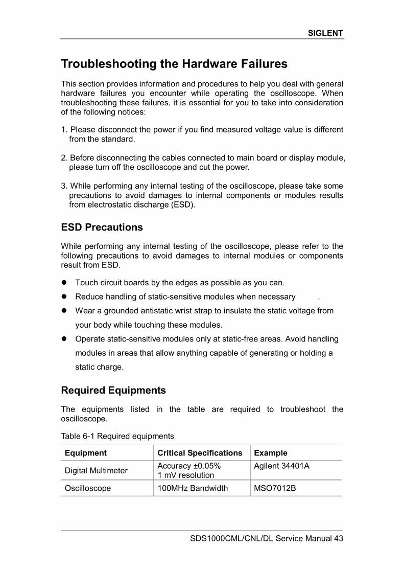
static charge. Required Equipments The equipments listed in the table are required to troubleshoot the oscilloscope. Table 6-1 Required equipments
Equipment Critical Specifications Example
Digital Multimeter Accuracy ±0.05% 1 mV resolution
Agilent 34401A
Oscilloscope 100MHz Bandwidth MSO7012B
SIGLENT
44 SDS1000CML/CNL/DL Service Manual
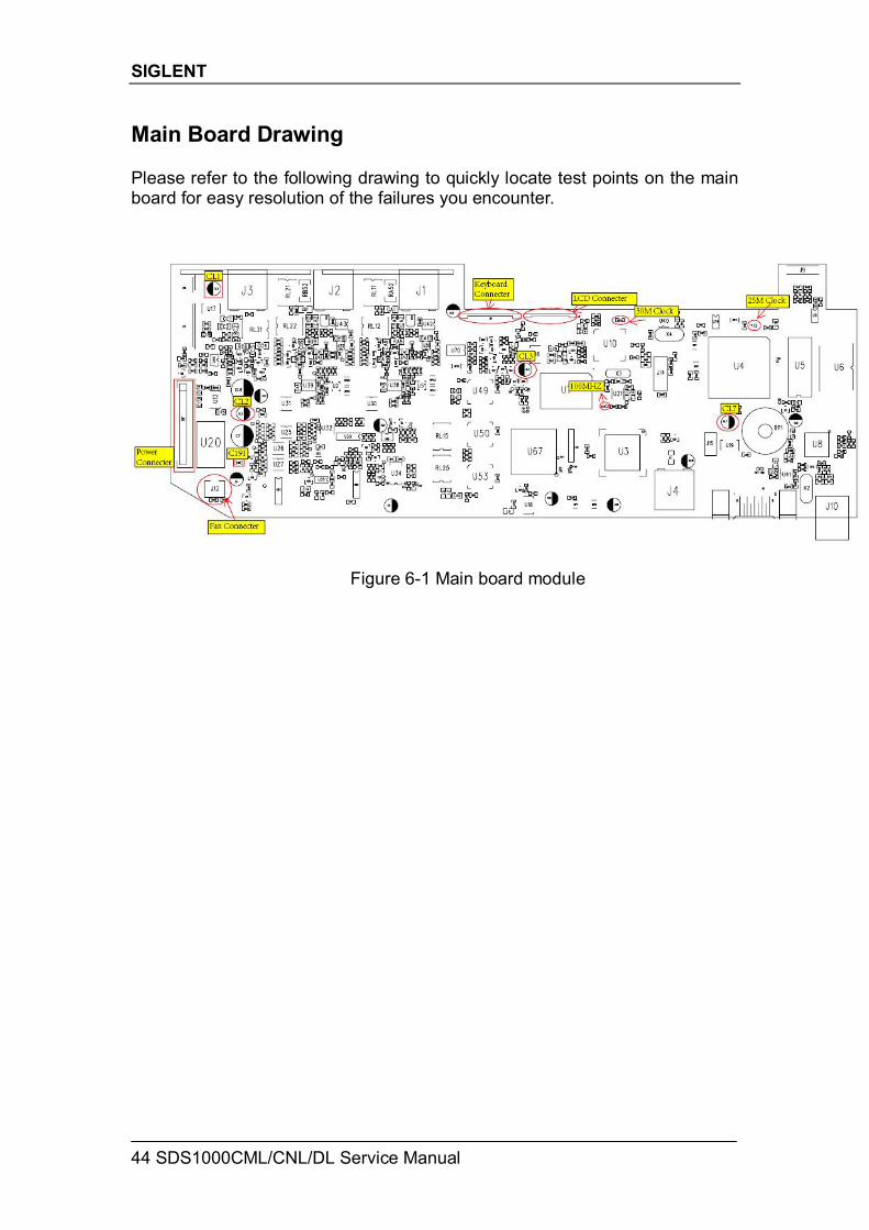
Main Board Drawing Please refer to the following drawing to quickly locate test points on the main board for easy resolution of the failures you encounter.
Figure 6-1 Main board module
SIGLENT
SDS1000CML/CNL/DL Service Manual 45
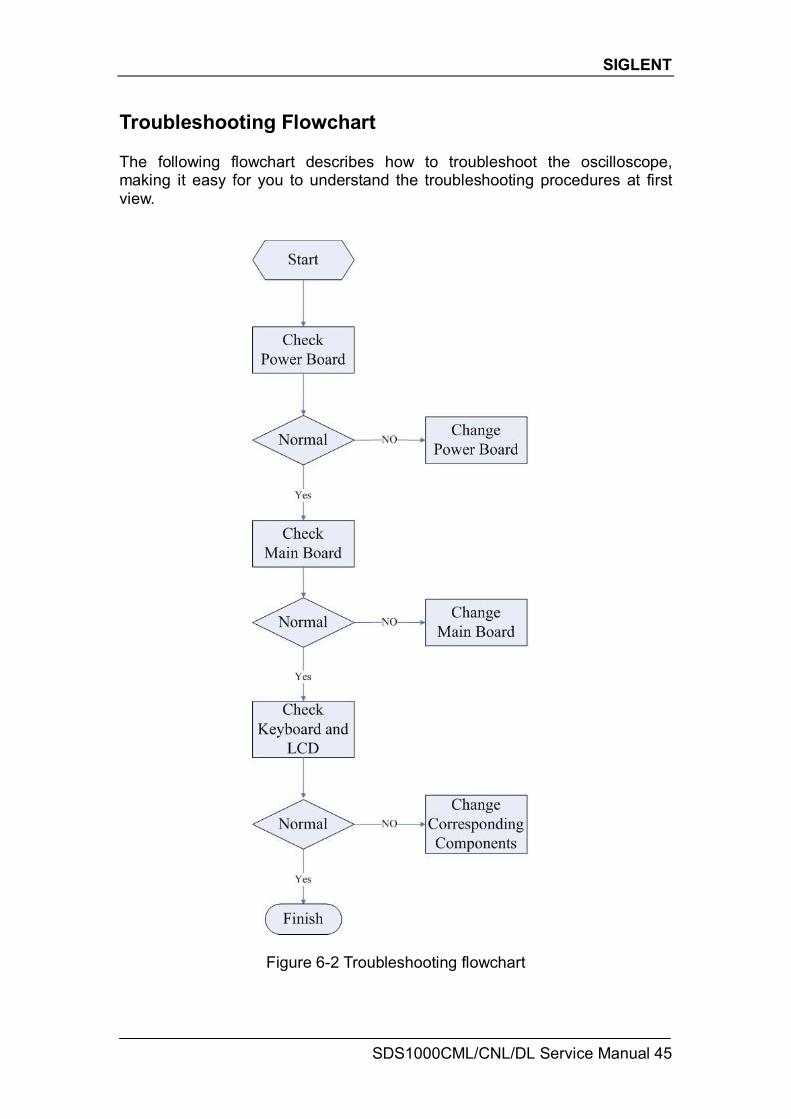
Troubleshooting Flowchart The following flowchart describes how to troubleshoot the oscilloscope, making it easy for you to understand the troubleshooting procedures at first view.
Figure 6-2 Troubleshooting flowchart
SIGLENT
46 SDS1000CML/CNL/DL Service Manual
Check the Power Supply Before performing the power supply testing procedure, please make sure that the oscilloscope is grounded through the protective lead of the power cord. take care not to touch or even disassemble the power supply module without any safety precautions, or you may probably suffer from electric shock or burn. Here are procedures for testing the power supply: 1. Disconnect the power cord of the oscilloscope and then check whether the
fuse has been burnt out. 2. Remove metallic cover of the power supply module using a driver, and then
connect the power cord. 3. Focus at the Power Connector which contains 12 pins from Pin1 to Pin12 on
the main board. You can test voltages provided by power supply at these points to check whether the voltage values are within specified range using a digital multimeter. The voltage parameters to be tested are listed in table below:
Table 6-2 Voltage parameters of the power supply module
Voltage value(V) Pin Error
0 (GND) Pin1, Pin5, Pin8, Pin12 NULL
15 Pin2 5%
6.3 Pin3, Pin4 10%
3.3 Pin6, Pin7 5%
-9 Pin9 10%
If each tested voltage value is within the spec range referring to the table above, then check the power-supply ripple using an oscilloscope. If the ripple appears small, then the power supply works normally. Otherwise, it proves to be faulted; If there is at least one tested voltage value beyond the spec range, please go to the next step.
4. Disconnect the cable connected to main board, and then perform the testing
procedures as the table above again: If each tested voltage value is within spec range referring to the table above, then it is the failure of the main board load that leads to problematic power supply. Continuous checking or even replacing the main board is required for further test. If there is at least one tested voltage value beyond the spec range, then the power supply module proves faulted and a new one is needed. For safety, please do not disassemble the power supply module by yourself.
SIGLENT
SDS1000CML/CNL/DL Service Manual 47
Check the Main Board If you want to remove the main board from the metal shelf inside the oscilloscope, you’d better place it on a clean, insulated mat. In addition, to avoid some chips or components on the main board being damaged for overheating, it is essential to cool the main board whenever possible using a fan. Here are procedures for testing the main board: 1. Several kinds of connectors including Fan Connector, LCD Connector and
Keypad Connector are located on the main board. Check if all these connectors are connected properly.
2. Make sure that the connectors on the main board are properly connected,
then connect the power supply module cable to appointed place of the main board, lastly connect the oscilloscope power cord and turn on the oscilloscope. Check if the voltage values at all test points are within the spec range using a digital multimeter. The voltage parameters to be tested are listed in table below:
Table 6-3 Voltage parameters of the main board
Components tested Voltage (V) Error (V)
C191 -5 ±0.1
CL1 5 ±0.1
CL2 5 ±0.1
CL3 2.5 ±0.1
CL7 1.25 ±0.1 If there is at least one tested voltage value beyond the spec range referring
to the table above, please turn off the oscilloscope and cut the power immediately to avoid damage to the chips or even the main board due to its abnormal working. Otherwise, you need to replace a new main board as a consequence.
If each tested voltage value is within the spec range, please go to the next step.
3. Check if the Clock on the main board works normally using an oscilloscope.
Focus at the test clock T53 marked with “100M Clock” on the main board drawing. If the clock measured is not 100M, then the failure may come from the main board, a new one is required necessary. If the clock measured is 100M, then go on to test if the clock T4 is 25MHz. If it is, then the main board proves normal. Or you need to return the oscilloscope to manufacturer to have it repaired by qualified personnel.
SIGLENT
48 SDS1000CML/CNL/DL Service Manual
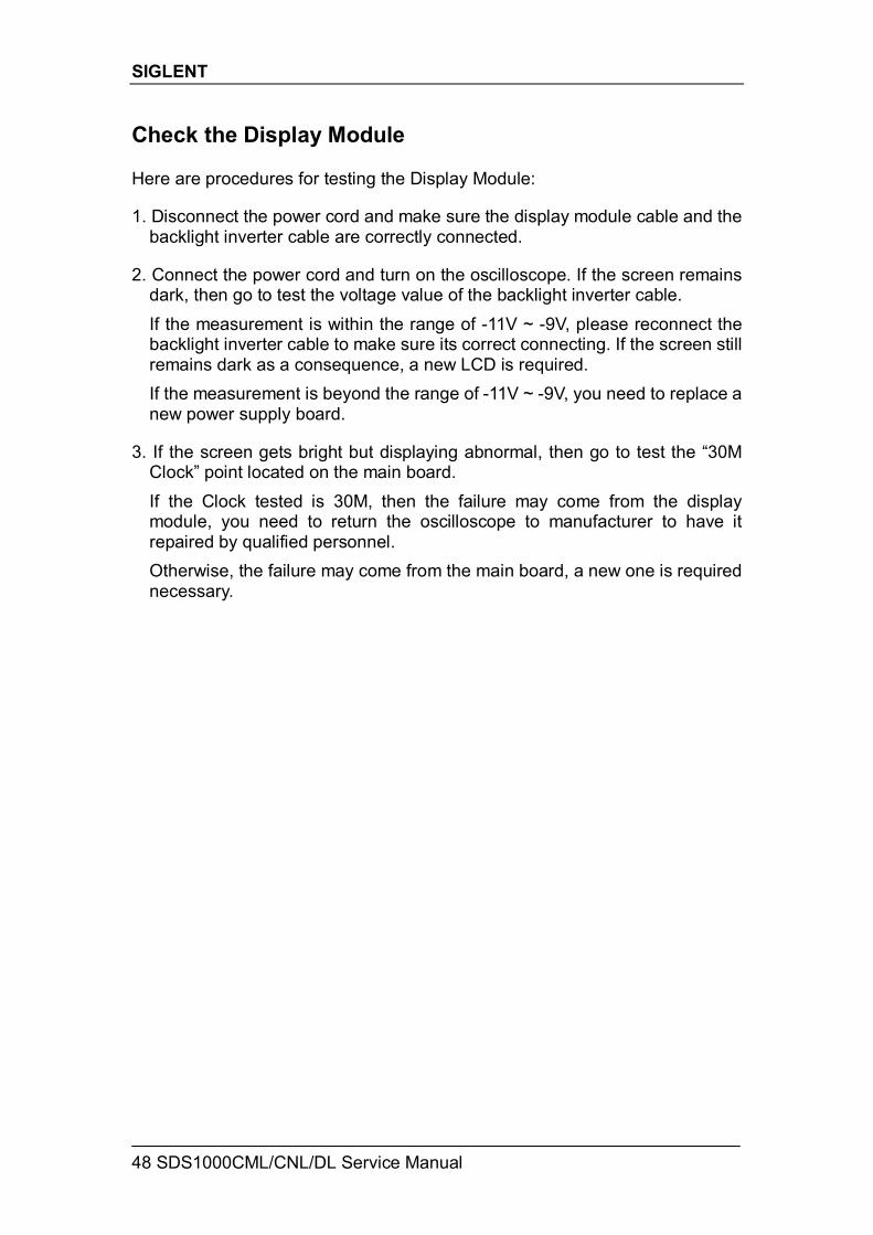
Check the Display Module Here are procedures for testing the Display Module: 1. Disconnect the power cord and make sure the display module cable and the
backlight inverter cable are correctly connected. 2. Connect the power cord and turn on the oscilloscope. If the screen remains
dark, then go to test the voltage value of the backlight inverter cable. If the measurement is within the range of -11V ~ -9V, please reconnect the backlight inverter cable to make sure its correct connecting. If the screen still remains dark as a consequence, a new LCD is required. If the measurement is beyond the range of -11V ~ -9V, you need to replace a new power supply board.
3. If the screen gets bright but displaying abnormal, then go to test the “30M
Clock” point located on the main board. If the Clock tested is 30M, then the failure may come from the display module, you need to return the oscilloscope to manufacturer to have it repaired by qualified personnel.
Otherwise, the failure may come from the main board, a new one is required necessary.
SIGLENT
SDS1000CML/CNL/DL Service Manual 49
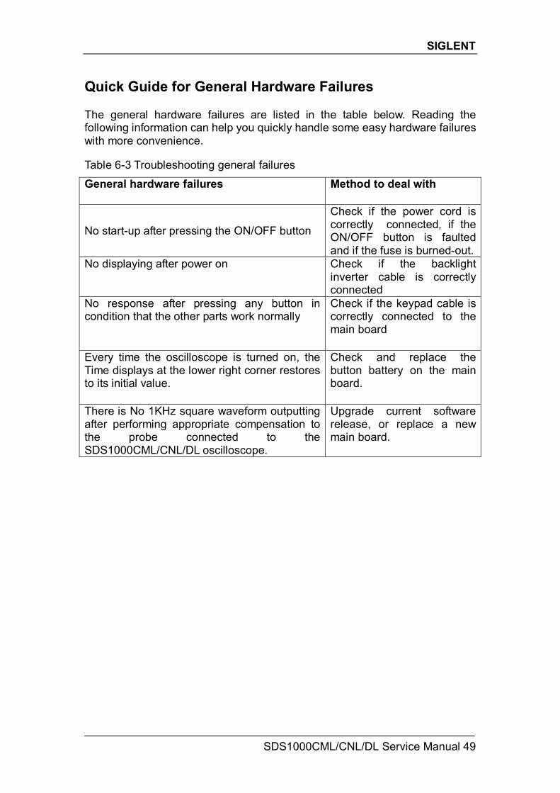
Quick Guide for General Hardware Failures The general hardware failures are listed in the table below. Reading the following information can help you quickly handle some easy hardware failures with more convenience. Table 6-3 Troubleshooting general failures
General hardware failures Method to deal with
No start-up after pressing the ON/OFF button
Check if the power cord is correctly connected, if the ON/OFF button is faulted and if the fuse is burned-out.
No displaying after power on Check if the backlight inverter cable is correctly connected
No response after pressing any button in condition that the other parts work normally
Check if the keypad cable is correctly connected to the main board
Every time the oscilloscope is turned on, the Time displays at the lower right corner restores to its initial value.
Check and replace the button battery on the main board.
There is No 1KHz square waveform outputting after performing appropriate compensation to the probe connected to the SDS1000CML/CNL/DL oscilloscope.
Upgrade current software release, or replace a new main board.
SIGLENT
50 SDS1000CML/CNL/DL Service Manual
Maintenance
Maintain summary SIGLENT warrants that the products it manufactures and sells are free from defects in materials and workmanship for a period of three years from the date of shipment from an authorized SIGLENT distributor. If a product or CRT proves defective within the respective period, SIGLENT will provide repair or replacement as described in the complete warranty statement. To arrange for service or obtain a copy of the complete warranty statement, please contact your nearest SIGLENT sales and service office. Except that as provided in this summary or the applicable warranty Statement, SIGLENT makes no warranty of any kind, express or implied, including without limitation the implied warranties of merchantability and fitness for a particular purpose. In no case shall SIGLENT be liable for indirect, special or consequential damages
Inspecting and Care This section explains how to inspect the oscilloscope and shipping container as well as general care and cleaning of the oscilloscope. Here are detailed contents about this.
General Inspecting 1. Inspect the shipping container.
Keep the damaged shipping container or cushioning material until the contents of the shipment have been completely checked and the instrument has passed both electrical and mechanical tests. The consigner or carrier will be responsible for damages to the instrument resulting from shipment. SIGLENT would not provide free maintenance or replacement.
2. Inspect the instrument.
If there are instruments found damaged, defective or failure in electrical and mechanical tests, please contact SIGLENT.
3. Check the accessories.
Please check the accessories according to the packing list. If the accessories are incomplete or damaged, please contact your SIGLENT sales representative.
SIGLENT
SDS1000CML/CNL/DL Service Manual 51
Standard Accessories: Two pieces 1:1/(10:1) Passive Probes
An User Manual
A Certification
A Guaranty Card
An CD(including EasyScope3.0 computer software system)
A Power Cord that fits the standard of destination country
An USB Cable
General Care and Cleaning Care: Do not store or leave the instrument in direct sunshine for long periods of time. Notice: To avoid damages to the instrument or probe, please do not leave them in
fog, liquid, or solvent. Cleaning: Please perform the following steps to clean the instrument and probe regularly according to its operating conditions. 1. Disconnect the instrument from all power sources, and then clean it with a
soft wet cloth. 2. Clean the loose dust on the outside of the instrument and probe with a soft
cloth. When cleaning the LCD, take care to avoid scarifying it. Notice: To avoid damages to the surface of the instrument and probe, please do
not use any corrosive liquid or chemical cleanser. Make sure that the instrument is completely dry before restarting it to avoid
short circuits or personal injuries.
SIGLENT
52 SDS1000CML/CNL/DL Service Manual
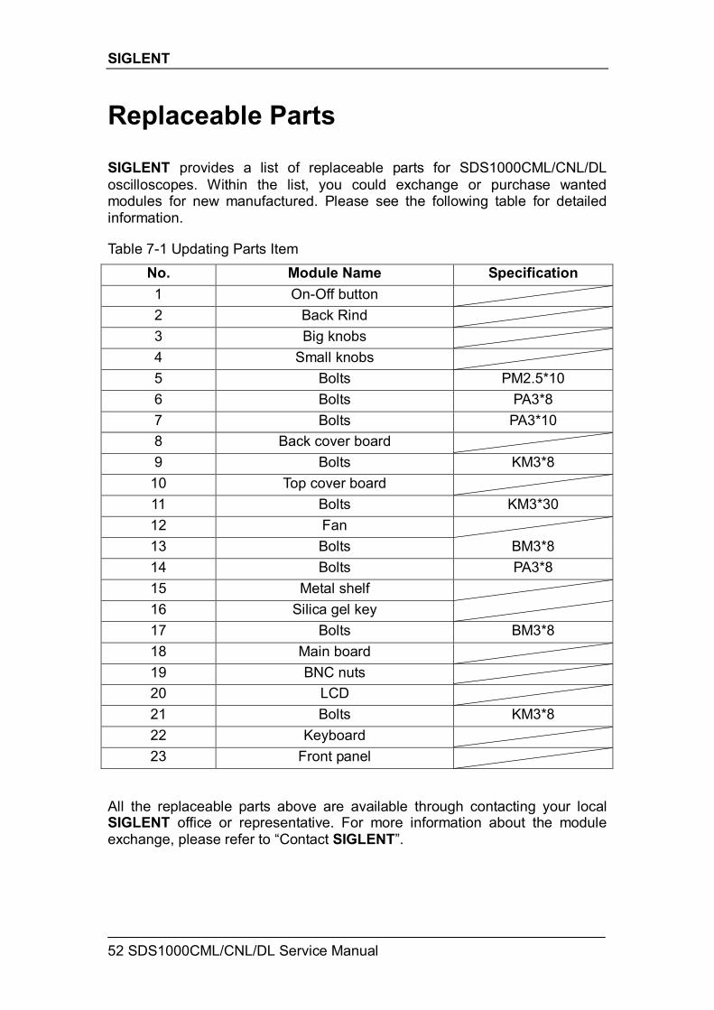
Replaceable Parts SIGLENT provides a list of replaceable parts for SDS1000CML/CNL/DL oscilloscopes. Within the list, you could exchange or purchase wanted modules for new manufactured. Please see the following table for detailed information. Table 7-1 Updating Parts Item
No. Module Name Specification 1 On-Off button 2 Back Rind 3 Big knobs 4 Small knobs 5 Bolts PM2.5*10 6 Bolts PA3*8 7 Bolts PA3*10 8 Back cover board 9 Bolts KM3*8
10 Top cover board 11 Bolts KM3*30 12 Fan 13 Bolts BM3*8 14 Bolts PA3*8 15 Metal shelf 16 Silica gel key 17 Bolts BM3*8 18 Main board 19 BNC nuts 20 LCD 21 Bolts KM3*8 22 Keyboard 23 Front panel
All the replaceable parts above are available through contacting your local SIGLENT office or representative. For more information about the module exchange, please refer to “Contact SIGLENT”.

SIGLENT
SDS1000CML/CNL/DL Service Manual 53
Contact SIGLENT SIGLENT TECHNOLOGIES CO., LTD
Address:3/F, building NO.4, Antongda Industrial Zone, 3rd Liuxian
Road, Bao’an District, Shenzhen, P.R.China
Tel:0086-755-3661 5186
E-mail:[email protected]
http://www.siglent.com