Embed Size (px)
Citation preview
WIKA data sheet LM 33.01
Page 1 of 27
Level measurement
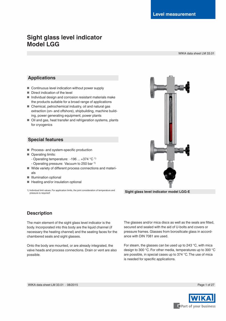
Sight glass level indicatorModel LGG
Sight glass level indicator model LGG-E
Applications
■ Continuous level indication without power supply ■ Direct indication of the level ■ Individual design and corrosion resistant materials make
the products suitable for a broad range of applications ■ Chemical, petrochemical industry, oil and natural gas
extraction (on- and offshore), shipbuilding, machine build-ing, power generating equipment, power plants
■ Oil and gas, heat transfer and refrigeration systems, plants for cryogenics
Special features
■ Process- and system-specific production ■ Operating limits:
- Operating temperature: -196 ... +374 °C 1)
- Operating pressure: Vacuum to 250 bar 1)
■ Wide variety of different process connections and materi-als
■ Illumination optional ■ Heating and/or insulation optional
1) Individual limit values. For application limits, the joint consideration of temperature and pressure is required!
Description
The main element of the sight glass level indicator is the body. Incorporated into this body are the liquid channel (if necessary the heating channel) and the seating faces for the chambered seals and sight glasses.
Onto the body are mounted, or are already integrated, the valve heads and process connections. Drain or vent are also possible.
The glasses and/or mica discs as well as the seals are fitted, secured and sealed with the aid of U-bolts and covers or pressure frames. Glasses from borosilicate glass in accord-ance with DIN 7081 are used.
For steam, the glasses can be used up to 243 °C, with mica design to 300 °C. For other media, temperatures up to 300 °C are possible, in special cases up to 374 °C. The use of mica is needed for specific applications.
WIKA data sheet LM 33.01 ∙ 08/2015
Page 2 of 27 WIKA data sheet LM 33.01 ∙ 08/2015
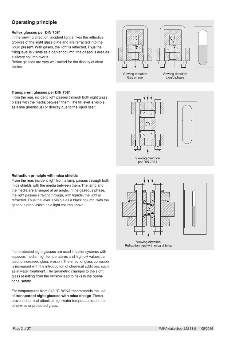
Operating principle
Reflex glasses per DIN 7081In the viewing direction, incident light strikes the reflective grooves of the sight glass plate and are refracted into the liquid present. With gases, the light is reflected. Thus the filling level is visible as a darker column, the gaseous area as a silvery column over it.Reflex glasses are very well suited for the display of clear liquids.
Refraction principle with mica shieldsFrom the rear, incident light from a lamp passes through both mica shields with the media between them. The lamp and the media are arranged at an angle. In the gaseous phase, the light passes straight through, with liquids, the light is refracted. Thus the level is visible as a black column, with the gaseous area visible as a light column above.
Transparent glasses per DIN 7081From the rear, incident light passes through both sight glass plates with the media between them. The fill level is visible as a line (meniscus) or directly due to the liquid itself.
Viewing directionGas phase
Viewing directionLiquid phase
Viewing directionper DIN 7081
Viewing directionRefraction type with mica shields
If unprotected sight glasses are used in boiler systems with aqueous media, high temperatures and high pH values can lead to increased glass erosion. The effect of glass corrosion is increased with the introduction of chemical additives, such as in water treatment. The geometric changes to the sight glass resulting from the erosion lead to risks in the opera-tional safety.
For temperatures from 243 °C, WIKA recommends the use of transparent sight glasses with mica design. These prevent chemical attack at high water temperatures on the otherwise unprotected glass.
WIKA data sheet LM 33.01 ∙ 08/2015 Page 3 of 27
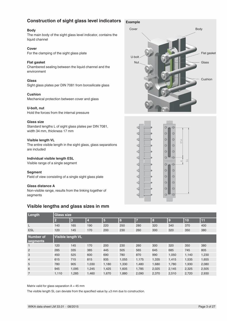
Example
Flat gasket
Cushion
Glass
Cover
Construction of sight glass level indicators
BodyThe main body of the sight glass level indicator, contains the liquid channel
CoverFor the clamping of the sight glass plate
Flat gasketChambered sealing between the liquid channel and the environment
GlassSight glass plates per DIN 7081 from borosilicate glass
CushionMechanical protection between cover and glass
U-bolt, nutHold the forces from the internal pressure
Glass sizeStandard lengths L of sight glass plates per DIN 7081, width 34 mm, thickness 17 mm
Visible length VLThe entire visible length in the sight glass, glass separations are included
Individual visible length ESLVisible range of a single segment
SegmentField of view consisting of a single sight glass plate
Glass distance ANon-visible range, results from the linking together of segments
U-boltNut
Body
Length Glass size2 3 4 5 6 7 8 9 10 11
L 140 165 190 220 250 280 320 340 370 400ESL 120 145 170 200 230 260 300 320 350 380
Number of segments
Visible length VL
1 120 145 170 200 230 260 300 320 350 3802 285 335 385 445 505 565 645 685 745 8053 450 525 600 690 780 870 990 1,050 1,140 1,2304 615 715 815 935 1,055 1,175 1,335 1,415 1,535 1,6555 780 905 1,030 1,180 1,330 1,480 1,680 1,780 1,930 2,0806 945 1,095 1,245 1,425 1,605 1,785 2,025 2,145 2,325 2,5057 1,110 1,285 1,460 1,670 1,880 2,090 2,370 2,510 2,720 2,930
Visible lengths and glass sizes in mm
Matrix valid for glass separation A = 45 mmThe visible length SL can deviate from the specified value by ±3 mm due to construction.
Page 4 of 27 WIKA data sheet LM 33.01 ∙ 08/2015
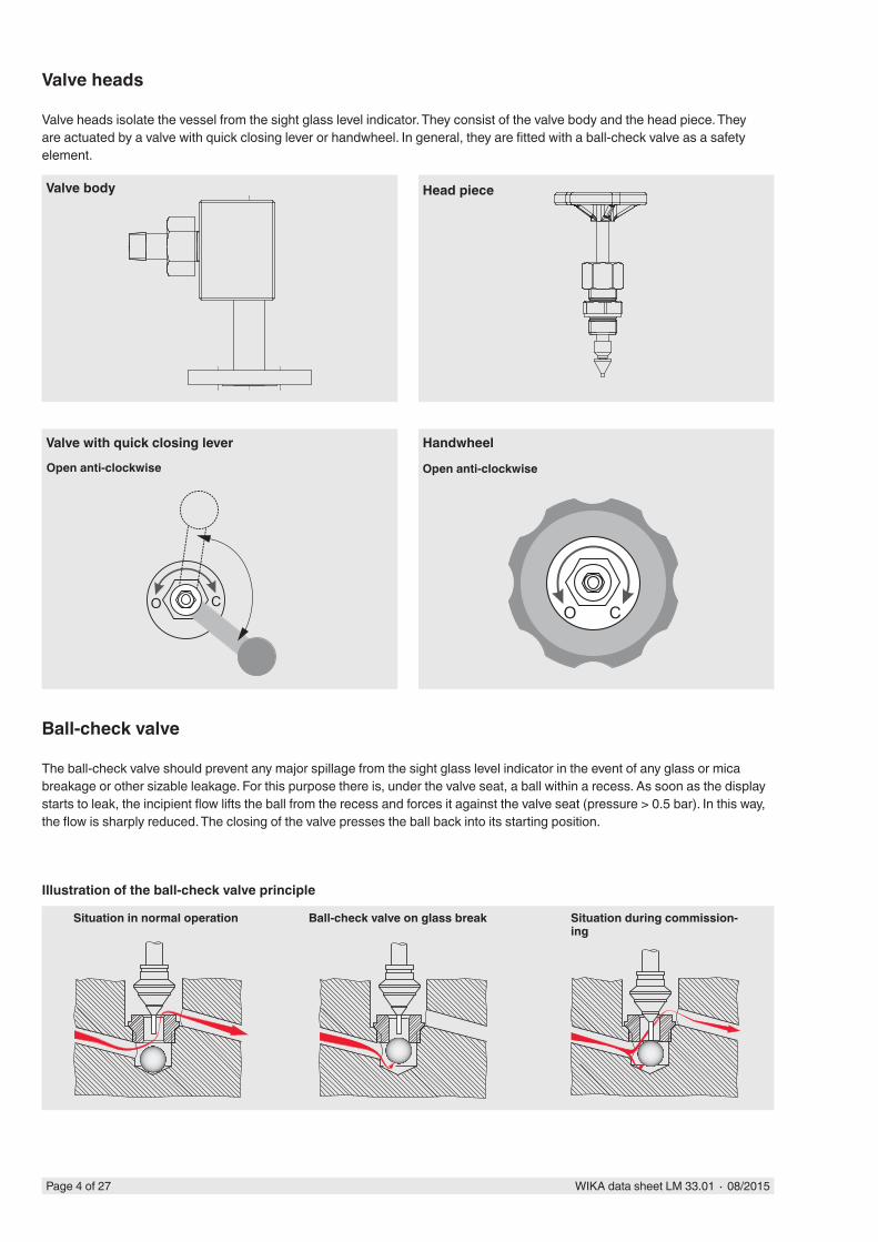
Open anti-clockwise Open anti-clockwise
Valve heads
Valve heads isolate the vessel from the sight glass level indicator. They consist of the valve body and the head piece. They are actuated by a valve with quick closing lever or handwheel. In general, they are fitted with a ball-check valve as a safety element.
Head piece
Valve with quick closing lever Handwheel
Ball-check valve
The ball-check valve should prevent any major spillage from the sight glass level indicator in the event of any glass or mica breakage or other sizable leakage. For this purpose there is, under the valve seat, a ball within a recess. As soon as the display starts to leak, the incipient flow lifts the ball from the recess and forces it against the valve seat (pressure > 0.5 bar). In this way, the flow is sharply reduced. The closing of the valve presses the ball back into its starting position.
Illustration of the ball-check valve principle
Situation in normal operation Ball-check valve on glass break Situation during commission-ing
Valve body
WIKA data sheet LM 33.01 ∙ 08/2015 Page 5 of 27
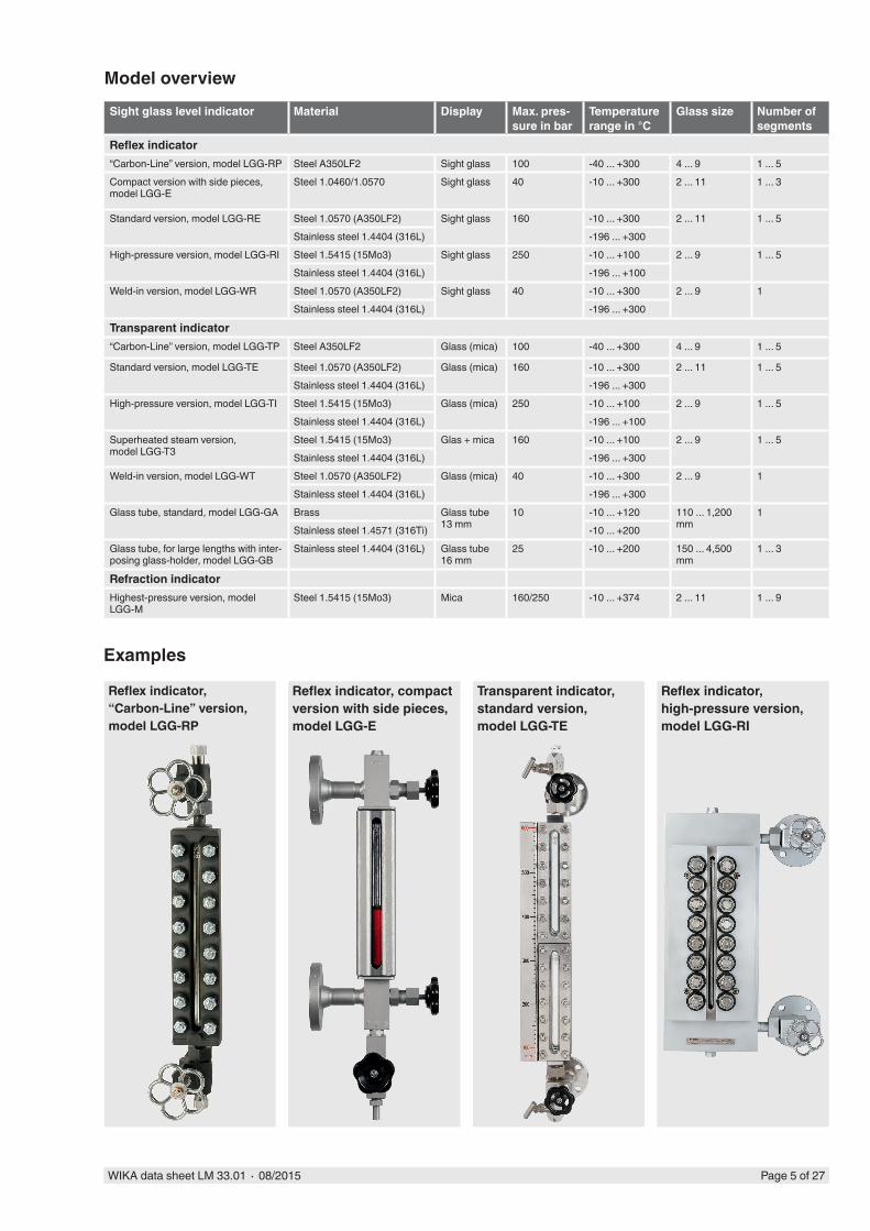
Model overviewSight glass level indicator Material Display Max. pres-
sure in barTemperature range in °C
Glass size Number of segments
Reflex indicator“Carbon-Line” version, model LGG-RP Steel A350LF2 Sight glass 100 -40 ... +300 4 ... 9 1 ... 5Compact version with side pieces, model LGG-E
Steel 1.0460/1.0570 Sight glass 40 -10 ... +300 2 ... 11 1 ... 3
Standard version, model LGG-RE Steel 1.0570 (A350LF2) Sight glass 160 -10 ... +300 2 ... 11 1 ... 5Stainless steel 1.4404 (316L) -196 ... +300
High-pressure version, model LGG-RI Steel 1.5415 (15Mo3) Sight glass 250 -10 ... +100 2 ... 9 1 ... 5 Stainless steel 1.4404 (316L) -196 ... +100
Weld-in version, model LGG-WR Steel 1.0570 (A350LF2) Sight glass 40 -10 ... +300 2 ... 9 1Stainless steel 1.4404 (316L) -196 ... +300
Transparent indicator“Carbon-Line” version, model LGG-TP Steel A350LF2 Glass (mica) 100 -40 ... +300 4 ... 9 1 ... 5
Standard version, model LGG-TE Steel 1.0570 (A350LF2) Glass (mica) 160 -10 ... +300 2 ... 11 1 ... 5Stainless steel 1.4404 (316L) -196 ... +300
High-pressure version, model LGG-TI Steel 1.5415 (15Mo3) Glass (mica) 250 -10 ... +100 2 ... 9 1 ... 5 Stainless steel 1.4404 (316L) -196 ... +100
Superheated steam version, model LGG-T3
Steel 1.5415 (15Mo3) Glas + mica 160 -10 ... +100 2 ... 9 1 ... 5 Stainless steel 1.4404 (316L) -196 ... +300
Weld-in version, model LGG-WT Steel 1.0570 (A350LF2) Glass (mica) 40 -10 ... +300 2 ... 9 1Stainless steel 1.4404 (316L) -196 ... +300
Glass tube, standard, model LGG-GA Brass Glass tube 13 mm
10 -10 ... +120 110 ... 1,200 mm
1Stainless steel 1.4571 (316Ti) -10 ... +200
Glass tube, for large lengths with inter-posing glass-holder, model LGG-GB
Stainless steel 1.4404 (316L) Glass tube 16 mm
25 -10 ... +200 150 ... 4,500 mm
1 ... 3
Refraction indicatorHighest-pressure version, model LGG-M
Steel 1.5415 (15Mo3) Mica 160/250 -10 ... +374 2 ... 11 1 ... 9
Examples
Reflex indicator, “Carbon-Line” version, model LGG-RP
Reflex indicator, compact version with side pieces, model LGG-E
Transparent indicator, standard version, model LGG-TE
Reflex indicator, high-pressure version, model LGG-RI
Page 6 of 27 WIKA data sheet LM 33.01 ∙ 08/2015
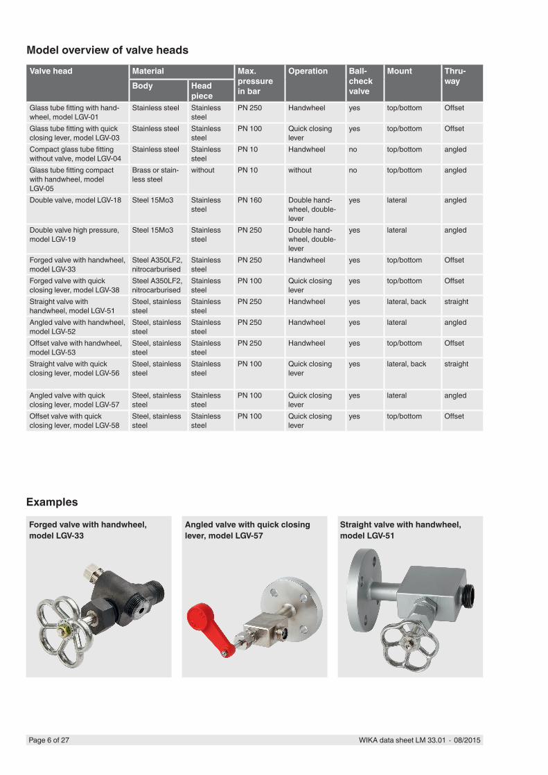
Model overview of valve heads
Valve head Material Max. pressure in bar
Operation Ball-check valve
Mount Thru-wayBody Head
pieceGlass tube fitting with hand-wheel, model LGV-01
Stainless steel Stainless steel
PN 250 Handwheel yes top/bottom Offset
Glass tube fitting with quick closing lever, model LGV-03
Stainless steel Stainless steel
PN 100 Quick closing lever
yes top/bottom Offset
Compact glass tube fitting without valve, model LGV-04
Stainless steel Stainless steel
PN 10 Handwheel no top/bottom angled
Glass tube fitting compact with handwheel, model LGV-05
Brass or stain-less steel
without PN 10 without no top/bottom angled
Double valve, model LGV-18 Steel 15Mo3 Stainless steel
PN 160 Double hand-wheel, double-lever
yes lateral angled
Double valve high pressure, model LGV-19
Steel 15Mo3 Stainless steel
PN 250 Double hand-wheel, double-lever
yes lateral angled
Forged valve with handwheel, model LGV-33
Steel A350LF2, nitrocarburised
Stainless steel
PN 250 Handwheel yes top/bottom Offset
Forged valve with quick closing lever, model LGV-38
Steel A350LF2, nitrocarburised
Stainless steel
PN 100 Quick closing lever
yes top/bottom Offset
Straight valve with handwheel, model LGV-51
Steel, stainless steel
Stainless steel
PN 250 Handwheel yes lateral, back straight
Angled valve with handwheel, model LGV-52
Steel, stainless steel
Stainless steel
PN 250 Handwheel yes lateral angled
Offset valve with handwheel, model LGV-53
Steel, stainless steel
Stainless steel
PN 250 Handwheel yes top/bottom Offset
Straight valve with quick closing lever, model LGV-56
Steel, stainless steel
Stainless steel
PN 100 Quick closing lever
yes lateral, back straight
Angled valve with quick closing lever, model LGV-57
Steel, stainless steel
Stainless steel
PN 100 Quick closing lever
yes lateral angled
Offset valve with quick closing lever, model LGV-58
Steel, stainless steel
Stainless steel
PN 100 Quick closing lever
yes top/bottom Offset
Examples
Forged valve with handwheel, model LGV-33
Angled valve with quick closing lever, model LGV-57
Straight valve with handwheel, model LGV-51
WIKA data sheet LM 33.01 ∙ 08/2015 Page 7 of 27
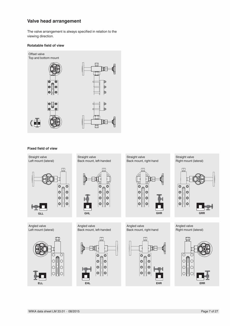
Straight valveLeft mount (lateral)
Straight valveBack mount, right-hand
Straight valveRight mount (lateral)
Angled valveLeft mount (lateral)
Angled valveBack mount, left-handed
Angled valveBack mount, right-hand
Angled valveRight mount (lateral)
GHR GRR
Straight valveBack mount, left-handed
Angled valveRight mount (lateral)
Valve head arrangement
The valve arrangement is always specified in relation to the viewing direction.
Rotatable field of view
Offset valveTop and bottom mount
Fixed field of view
GLL GHL
ELL EHL EHR ERR
Page 8 of 27 WIKA data sheet LM 33.01 ∙ 08/2015
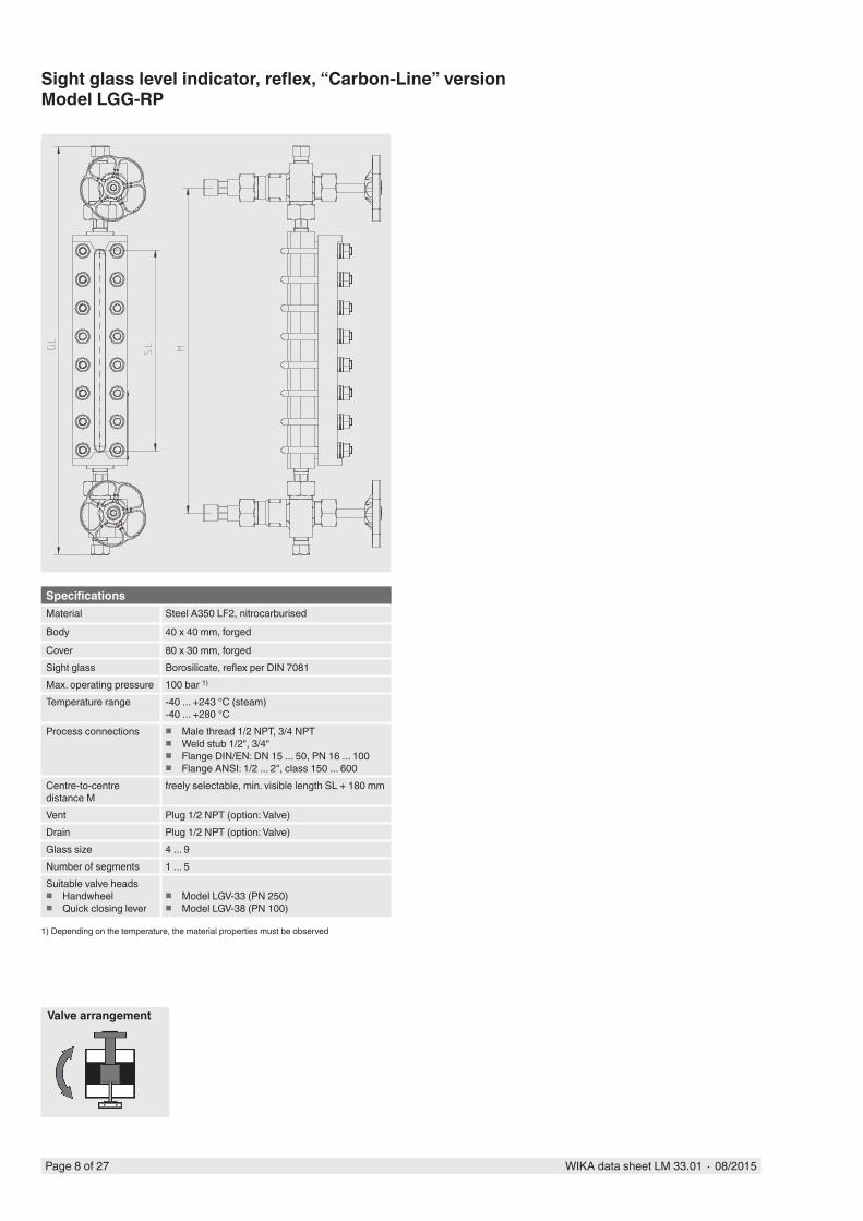
Sight glass level indicator, reflex, “Carbon-Line” versionModel LGG-RP
SpecificationsMaterial Steel A350 LF2, nitrocarburised
Body 40 x 40 mm, forged
Cover 80 x 30 mm, forgedSight glass Borosilicate, reflex per DIN 7081Max. operating pressure 100 bar 1)
Temperature range -40 ... +243 °C (steam)-40 ... +280 °C
Process connections � Male thread 1/2 NPT, 3/4 NPT � Weld stub 1/2", 3/4" � Flange DIN/EN: DN 15 ... 50, PN 16 ... 100 � Flange ANSI: 1/2 ... 2", class 150 ... 600
Centre-to-centre distance M
freely selectable, min. visible length SL + 180 mm
Vent Plug 1/2 NPT (option: Valve)Drain Plug 1/2 NPT (option: Valve)Glass size 4 ... 9Number of segments 1 ... 5Suitable valve heads
� Handwheel � Quick closing lever
� Model LGV-33 (PN 250) � Model LGV-38 (PN 100)
1) Depending on the temperature, the material properties must be observed
Valve arrangement
WIKA data sheet LM 33.01 ∙ 08/2015 Page 9 of 27
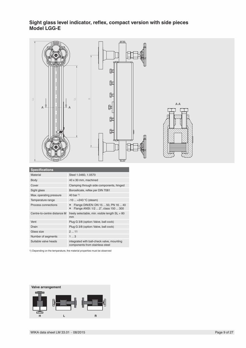
Sight glass level indicator, reflex, compact version with side piecesModel LGG-E
SpecificationsMaterial Steel 1.0460, 1.0570
Body 40 x 30 mm, machined
Cover Clamping through side components, hingedSight glass Borosilicate, reflex per DIN 7081Max. operating pressure 40 bar 1)
Temperature range -10 ... +243 °C (steam)Process connections � Flange DIN/EN: DN 15 ... 50, PN 16 ... 40
� Flange ANSI: 1/2 ... 2", class 150 ... 300Centre-to-centre distance M freely selectable, min. visible length SL + 80
mmVent Plug G 3/8 (option: Valve, ball cock)Drain Plug G 3/8 (option: Valve, ball cock)Glass size 2 ... 11Number of segments 1 ... 3Suitable valve heads integrated with ball-check valve, mounting
components from stainless steel
1) Depending on the temperature, the material properties must be observed
Valve arrangement
H L R
A AA-A
Page 10 of 27 WIKA data sheet LM 33.01 ∙ 08/2015
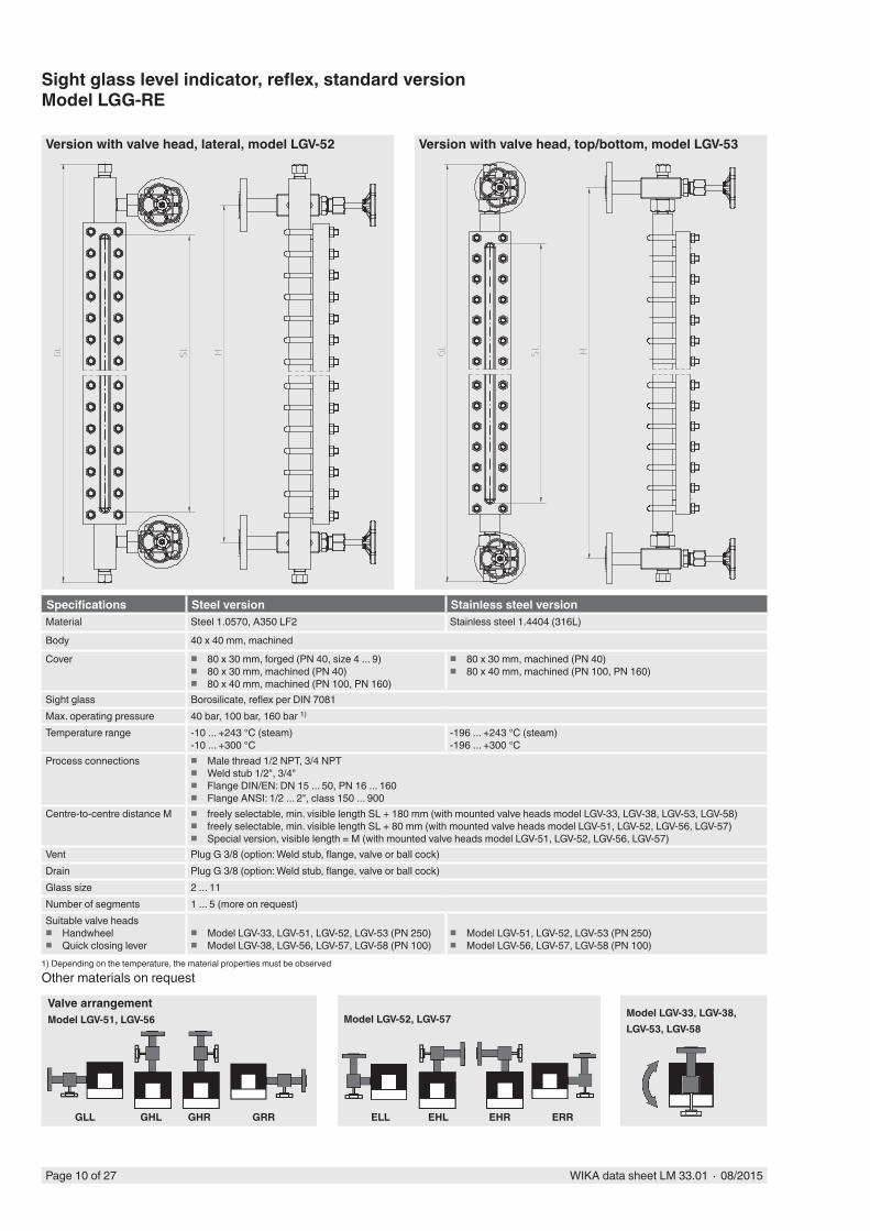
Sight glass level indicator, reflex, standard versionModel LGG-RE
Other materials on request
Specifications Steel version Stainless steel versionMaterial Steel 1.0570, A350 LF2 Stainless steel 1.4404 (316L)
Body 40 x 40 mm, machined
Cover � 80 x 30 mm, forged (PN 40, size 4 ... 9) � 80 x 30 mm, machined (PN 40) � 80 x 40 mm, machined (PN 100, PN 160)
� 80 x 30 mm, machined (PN 40) � 80 x 40 mm, machined (PN 100, PN 160)
Sight glass Borosilicate, reflex per DIN 7081Max. operating pressure 40 bar, 100 bar, 160 bar 1)
Temperature range -10 ... +243 °C (steam)-10 ... +300 °C
-196 ... +243 °C (steam)-196 ... +300 °C
Process connections � Male thread 1/2 NPT, 3/4 NPT � Weld stub 1/2", 3/4" � Flange DIN/EN: DN 15 ... 50, PN 16 ... 160 � Flange ANSI: 1/2 ... 2", class 150 ... 900
Centre-to-centre distance M � freely selectable, min. visible length SL + 180 mm (with mounted valve heads model LGV-33, LGV-38, LGV-53, LGV-58) � freely selectable, min. visible length SL + 80 mm (with mounted valve heads model LGV-51, LGV-52, LGV-56, LGV-57) � Special version, visible length = M (with mounted valve heads model LGV-51, LGV-52, LGV-56, LGV-57)
Vent Plug G 3/8 (option: Weld stub, flange, valve or ball cock)Drain Plug G 3/8 (option: Weld stub, flange, valve or ball cock)Glass size 2 ... 11Number of segments 1 ... 5 (more on request)Suitable valve heads
� Handwheel � Quick closing lever
� Model LGV-33, LGV-51, LGV-52, LGV-53 (PN 250) � Model LGV-38, LGV-56, LGV-57, LGV-58 (PN 100)
� Model LGV-51, LGV-52, LGV-53 (PN 250) � Model LGV-56, LGV-57, LGV-58 (PN 100)
1) Depending on the temperature, the material properties must be observed
Version with valve head, lateral, model LGV-52 Version with valve head, top/bottom, model LGV-53
Valve arrangementModel LGV-51, LGV-56
GLL GHL GHR GRR
Model LGV-52, LGV-57
ELL EHL EHR ERR
Model LGV-33, LGV-38, LGV-53, LGV-58
WIKA data sheet LM 33.01 ∙ 08/2015 Page 11 of 27
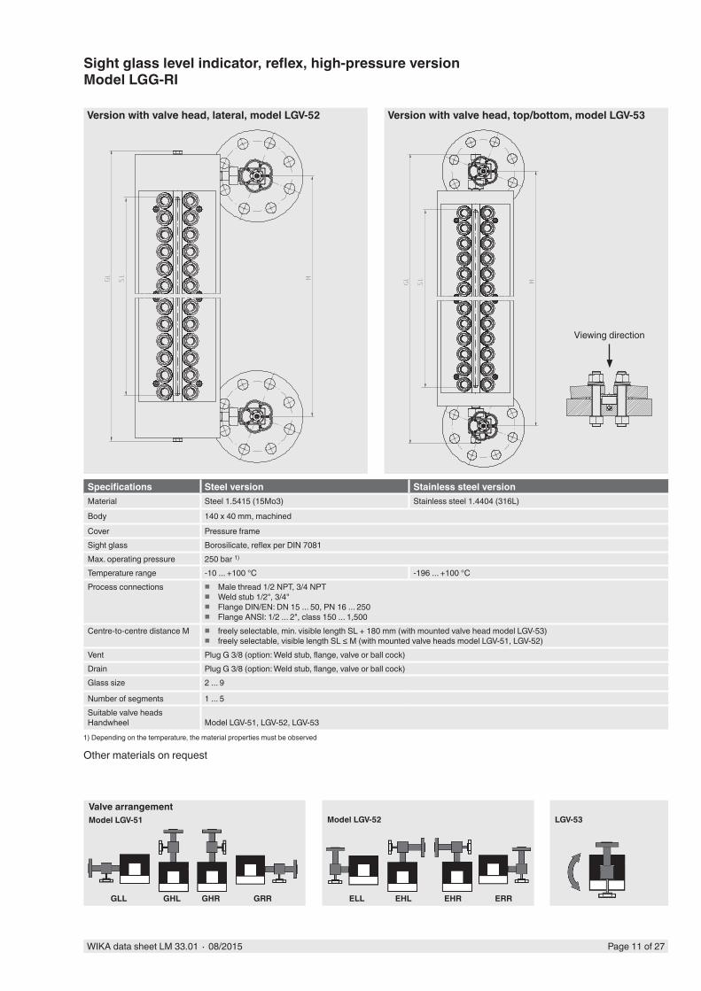
Sight glass level indicator, reflex, high-pressure versionModel LGG-RI
Other materials on request
Specifications Steel version Stainless steel versionMaterial Steel 1.5415 (15Mo3) Stainless steel 1.4404 (316L)
Body 140 x 40 mm, machined
Cover Pressure frameSight glass Borosilicate, reflex per DIN 7081Max. operating pressure 250 bar 1)
Temperature range -10 ... +100 °C -196 ... +100 °CProcess connections � Male thread 1/2 NPT, 3/4 NPT
� Weld stub 1/2", 3/4" � Flange DIN/EN: DN 15 ... 50, PN 16 ... 250 � Flange ANSI: 1/2 ... 2", class 150 ... 1,500
Centre-to-centre distance M � freely selectable, min. visible length SL + 180 mm (with mounted valve head model LGV-53) � freely selectable, visible length SL ≤ M (with mounted valve heads model LGV-51, LGV-52)
Vent Plug G 3/8 (option: Weld stub, flange, valve or ball cock)Drain Plug G 3/8 (option: Weld stub, flange, valve or ball cock)Glass size 2 ... 9
Number of segments 1 ... 5Suitable valve headsHandwheel Model LGV-51, LGV-52, LGV-53
1) Depending on the temperature, the material properties must be observed
Version with valve head, lateral, model LGV-52 Version with valve head, top/bottom, model LGV-53
Valve arrangementModel LGV-51
GLL GHL GHR GRR
Model LGV-52
ELL EHL EHR ERR
LGV-53
Viewing direction
Page 12 of 27 WIKA data sheet LM 33.01 ∙ 08/2015
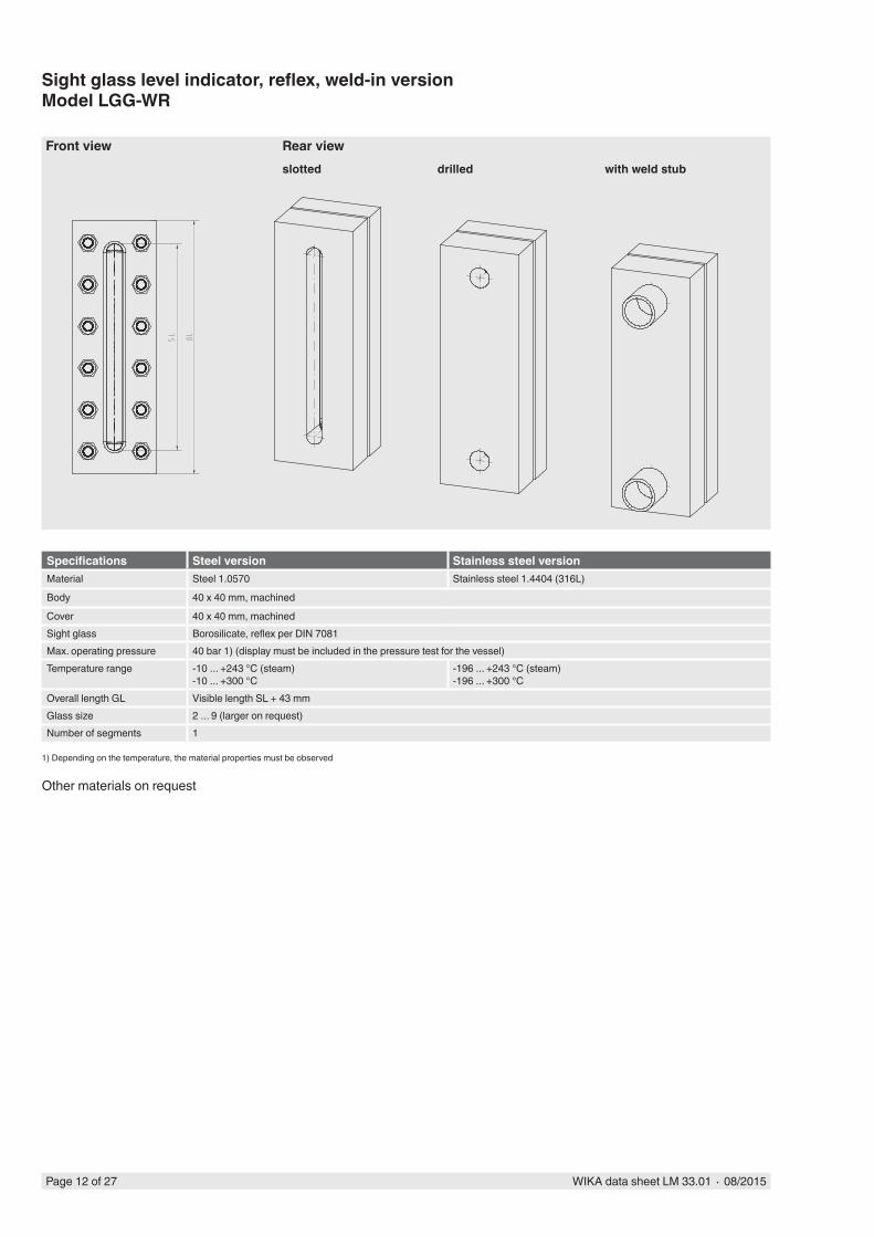
Sight glass level indicator, reflex, weld-in versionModel LGG-WR
Other materials on request
Specifications Steel version Stainless steel versionMaterial Steel 1.0570 Stainless steel 1.4404 (316L)
Body 40 x 40 mm, machined
Cover 40 x 40 mm, machinedSight glass Borosilicate, reflex per DIN 7081Max. operating pressure 40 bar 1) (display must be included in the pressure test for the vessel)Temperature range -10 ... +243 °C (steam)
-10 ... +300 °C-196 ... +243 °C (steam)-196 ... +300 °C
Overall length GL Visible length SL + 43 mmGlass size 2 ... 9 (larger on request)Number of segments 1
1) Depending on the temperature, the material properties must be observed
Front view Rear viewslotted drilled with weld stub
WIKA data sheet LM 33.01 ∙ 08/2015 Page 13 of 27
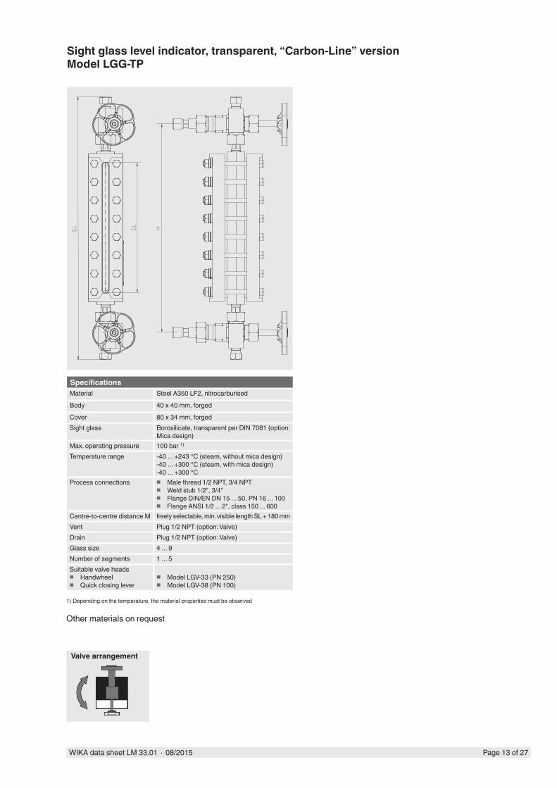
Sight glass level indicator, transparent, “Carbon-Line” versionModel LGG-TP
Other materials on request
SpecificationsMaterial Steel A350 LF2, nitrocarburised
Body 40 x 40 mm, forged
Cover 80 x 34 mm, forgedSight glass Borosilicate, transparent per DIN 7081 (option:
Mica design)Max. operating pressure 100 bar 1)
Temperature range -40 ... +243 °C (steam, without mica design)-40 ... +300 °C (steam, with mica design)-40 ... +300 °C
Process connections � Male thread 1/2 NPT, 3/4 NPT � Weld stub 1/2", 3/4" � Flange DIN/EN DN 15 ... 50, PN 16 ... 100 � Flange ANSI 1/2 ... 2", class 150 ... 600
Centre-to-centre distance M freely selectable, min. visible length SL + 180 mmVent Plug 1/2 NPT (option: Valve)Drain Plug 1/2 NPT (option: Valve)Glass size 4 ... 9Number of segments 1 ... 5Suitable valve heads
� Handwheel � Quick closing lever
� Model LGV-33 (PN 250) � Model LGV-38 (PN 100)
1) Depending on the temperature, the material properties must be observed
Valve arrangement
Page 14 of 27 WIKA data sheet LM 33.01 ∙ 08/2015
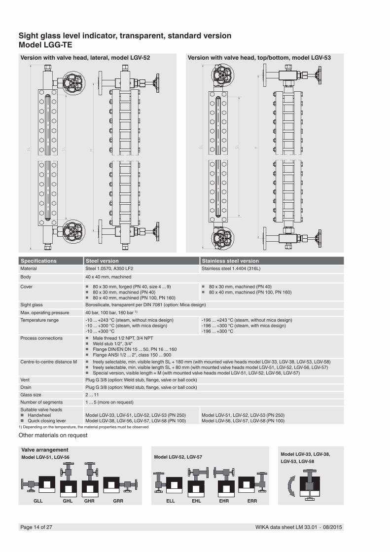
Sight glass level indicator, transparent, standard versionModel LGG-TE
Other materials on request
Specifications Steel version Stainless steel versionMaterial Steel 1.0570, A350 LF2 Stainless steel 1.4404 (316L)
Body 40 x 40 mm, machined
Cover � 80 x 30 mm, forged (PN 40, size 4 ... 9) � 80 x 30 mm, machined (PN 40) � 80 x 40 mm, machined (PN 100, PN 160)
� 80 x 30 mm, machined (PN 40) � 80 x 40 mm, machined (PN 100, PN 160)
Sight glass Borosilicate, transparent per DIN 7081 (option: Mica design)Max. operating pressure 40 bar, 100 bar, 160 bar 1)
Temperature range -10 ... +243 °C (steam, without mica design)-10 ... +300 °C (steam, with mica design)-10 ... +300 °C
-196 ... +243 °C (steam, without mica design)-196 ... +300 °C (steam, with mica design)-196 ... +300 °C
Process connections � Male thread 1/2 NPT, 3/4 NPT � Weld stub 1/2", 3/4" � Flange DIN/EN DN 15 ... 50, PN 16 ... 160 � Flange ANSI 1/2 ... 2", class 150 ... 900
Centre-to-centre distance M � freely selectable, min. visible length SL + 180 mm (with mounted valve heads model LGV-33, LGV-38, LGV-53, LGV-58) � freely selectable, min. visible length SL + 80 mm (with mounted valve heads model LGV-51, LGV-52, LGV-56, LGV-57) � Special version, visible length = M (with mounted valve heads model LGV-51, LGV-52, LGV-56, LGV-57)
Vent Plug G 3/8 (option: Weld stub, flange, valve or ball cock)Drain Plug G 3/8 (option: Weld stub, flange, valve or ball cock)Glass size 2 ... 11Number of segments 1 ... 5 (more on request)Suitable valve heads
■ Handwheel ■ Quick closing lever
Model LGV-33, LGV-51, LGV-52, LGV-53 (PN 250)Model LGV-38, LGV-56, LGV-57, LGV-58 (PN 100)
Model LGV-51, LGV-52, LGV-53 (PN 250)Model LGV-56, LGV-57, LGV-58 (PN 100)
1) Depending on the temperature, the material properties must be observed
Version with valve head, lateral, model LGV-52 Version with valve head, top/bottom, model LGV-53
Valve arrangementModel LGV-51, LGV-56
GLL GHL GHR GRR
Model LGV-52, LGV-57
ELL EHL EHR ERR
Model LGV-33, LGV-38, LGV-53, LGV-58
WIKA data sheet LM 33.01 ∙ 08/2015 Page 15 of 27
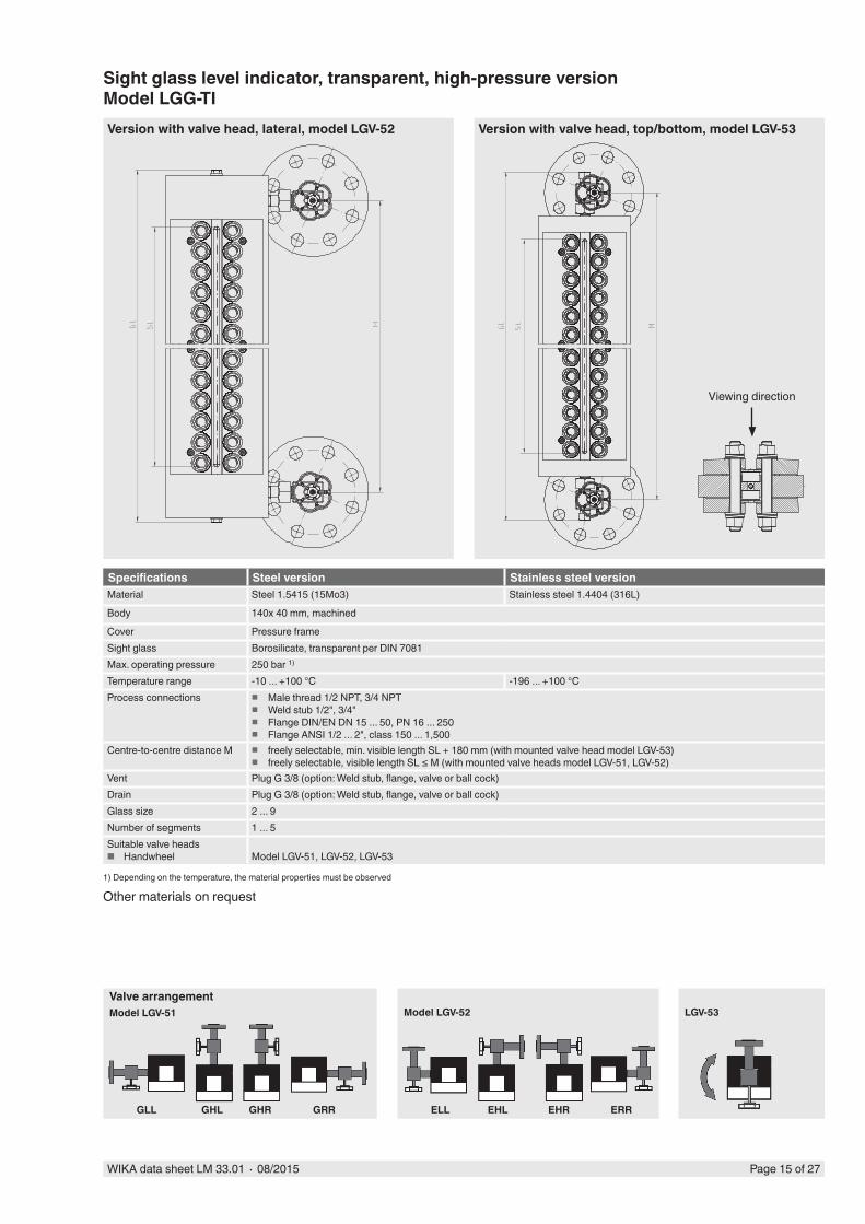
Sight glass level indicator, transparent, high-pressure versionModel LGG-TI
Other materials on request
Specifications Steel version Stainless steel versionMaterial Steel 1.5415 (15Mo3) Stainless steel 1.4404 (316L)
Body 140x 40 mm, machined
Cover Pressure frameSight glass Borosilicate, transparent per DIN 7081Max. operating pressure 250 bar 1)
Temperature range -10 ... +100 °C -196 ... +100 °CProcess connections � Male thread 1/2 NPT, 3/4 NPT
� Weld stub 1/2", 3/4" � Flange DIN/EN DN 15 ... 50, PN 16 ... 250 � Flange ANSI 1/2 ... 2", class 150 ... 1,500
Centre-to-centre distance M � freely selectable, min. visible length SL + 180 mm (with mounted valve head model LGV-53) � freely selectable, visible length SL ≤ M (with mounted valve heads model LGV-51, LGV-52)
Vent Plug G 3/8 (option: Weld stub, flange, valve or ball cock)Drain Plug G 3/8 (option: Weld stub, flange, valve or ball cock)Glass size 2 ... 9Number of segments 1 ... 5Suitable valve heads
■ Handwheel Model LGV-51, LGV-52, LGV-53
1) Depending on the temperature, the material properties must be observed
Version with valve head, lateral, model LGV-52 Version with valve head, top/bottom, model LGV-53
Valve arrangementModel LGV-51
GLL GHL GHR GRR
Model LGV-52
ELL EHL EHR ERR
LGV-53
Viewing direction
Page 16 of 27 WIKA data sheet LM 33.01 ∙ 08/2015
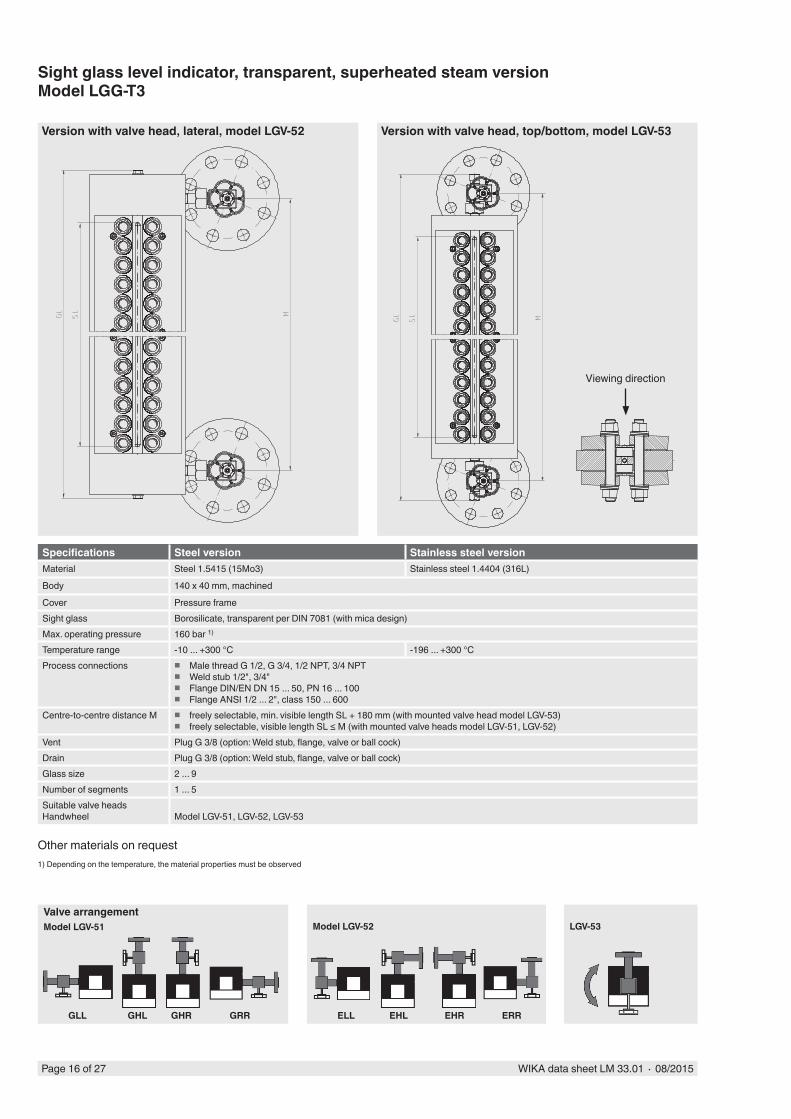
Sight glass level indicator, transparent, superheated steam versionModel LGG-T3
Other materials on request
Specifications Steel version Stainless steel versionMaterial Steel 1.5415 (15Mo3) Stainless steel 1.4404 (316L)
Body 140 x 40 mm, machined
Cover Pressure frameSight glass Borosilicate, transparent per DIN 7081 (with mica design)Max. operating pressure 160 bar 1)
Temperature range -10 ... +300 °C -196 ... +300 °CProcess connections � Male thread G 1/2, G 3/4, 1/2 NPT, 3/4 NPT
� Weld stub 1/2", 3/4" � Flange DIN/EN DN 15 ... 50, PN 16 ... 100 � Flange ANSI 1/2 ... 2", class 150 ... 600
Centre-to-centre distance M � freely selectable, min. visible length SL + 180 mm (with mounted valve head model LGV-53) � freely selectable, visible length SL ≤ M (with mounted valve heads model LGV-51, LGV-52)
Vent Plug G 3/8 (option: Weld stub, flange, valve or ball cock)Drain Plug G 3/8 (option: Weld stub, flange, valve or ball cock)Glass size 2 ... 9Number of segments 1 ... 5Suitable valve headsHandwheel Model LGV-51, LGV-52, LGV-53
1) Depending on the temperature, the material properties must be observed
Version with valve head, lateral, model LGV-52 Version with valve head, top/bottom, model LGV-53
Valve arrangementModel LGV-51
GLL GHL GHR GRR
Model LGV-52
ELL EHL EHR ERR
LGV-53
Viewing direction
WIKA data sheet LM 33.01 ∙ 08/2015 Page 17 of 27
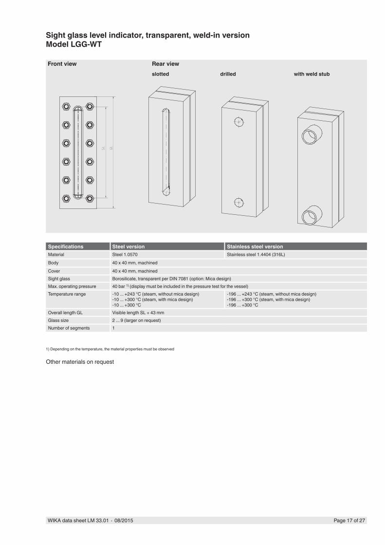
Sight glass level indicator, transparent, weld-in versionModel LGG-WT
Other materials on request
Specifications Steel version Stainless steel versionMaterial Steel 1.0570 Stainless steel 1.4404 (316L)
Body 40 x 40 mm, machined
Cover 40 x 40 mm, machinedSight glass Borosilicate, transparent per DIN 7081 (option: Mica design)Max. operating pressure 40 bar 1) (display must be included in the pressure test for the vessel)Temperature range -10 ... +243 °C (steam, without mica design)
-10 ... +300 °C (steam, with mica design)-10 ... +300 °C
-196 ... +243 °C (steam, without mica design)-196 ... +300 °C (steam, with mica design)-196 ... +300 °C
Overall length GL Visible length SL + 43 mmGlass size 2 ... 9 (larger on request)Number of segments 1
1) Depending on the temperature, the material properties must be observed
Front view Rear viewslotted drilled with weld stub
Page 18 of 27 WIKA data sheet LM 33.01 ∙ 08/2015
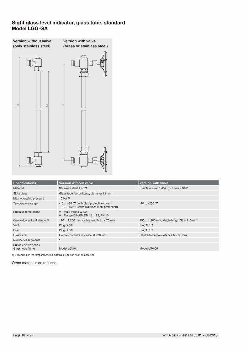
Sight glass level indicator, glass tube, standardModel LGG-GA
Other materials on request
Specifications Version without valve Version with valveMaterial Stainless steel 1.4571 Stainless steel 1.4571 or brass 2.0401
Sight glass Glass tube, borosilicate, diameter 13 mmMax. operating pressure 10 bar 1)
Temperature range -10 ... +80 °C (with plexi protective cover)-10 ... +150 °C (with stainless steel protection)
-10 ... +200 °C
Process connections � Male thread G 1/2 � Flange DIN/EN DN 15 ... 25, PN 10
Centre-to-centre distance M 110 ... 1,200 mm, visible length SL + 70 mm 150 ... 1,200 mm, visible length SL + 110 mmVent Plug G 3/8 Plug G 1/2Drain Plug G 3/8 Plug G 1/2Glass size Centre-to-centre distance M - 20 mm Centre-to-centre distance M - 65 mmNumber of segments 1Suitable valve headsGlass tube fitting Model LGV-04 Model LGV-05
1) Depending on the temperature, the material properties must be observed
Version without valve(only stainless steel)
Version with valve(brass or stainless steel)
WIKA data sheet LM 33.01 ∙ 08/2015 Page 19 of 27
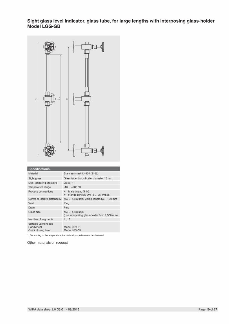
Sight glass level indicator, glass tube, for large lengths with interposing glass-holderModel LGG-GB
Other materials on request
SpecificationsMaterial Stainless steel 1.4404 (316L)
Sight glass Glass tube, borosilicate, diameter 16 mmMax. operating pressure 25 bar 1)Temperature range -10 ... +200 °CProcess connections � Male thread G 1/2
� Flange DIN/EN DN 15 ... 25, PN 25Centre-to-centre distance M 150 ... 4,500 mm, visible length SL + 130 mmVent PlugDrain PlugGlass size 150 ... 4,500 mm
(use interposing glass-holder from 1,500 mm)Number of segments 1 ... 3Suitable valve headsHandwheelQuick closing lever
Model LGV-01Model LGV-03
1) Depending on the temperature, the material properties must be observed
Page 20 of 27 WIKA data sheet LM 33.01 ∙ 08/2015
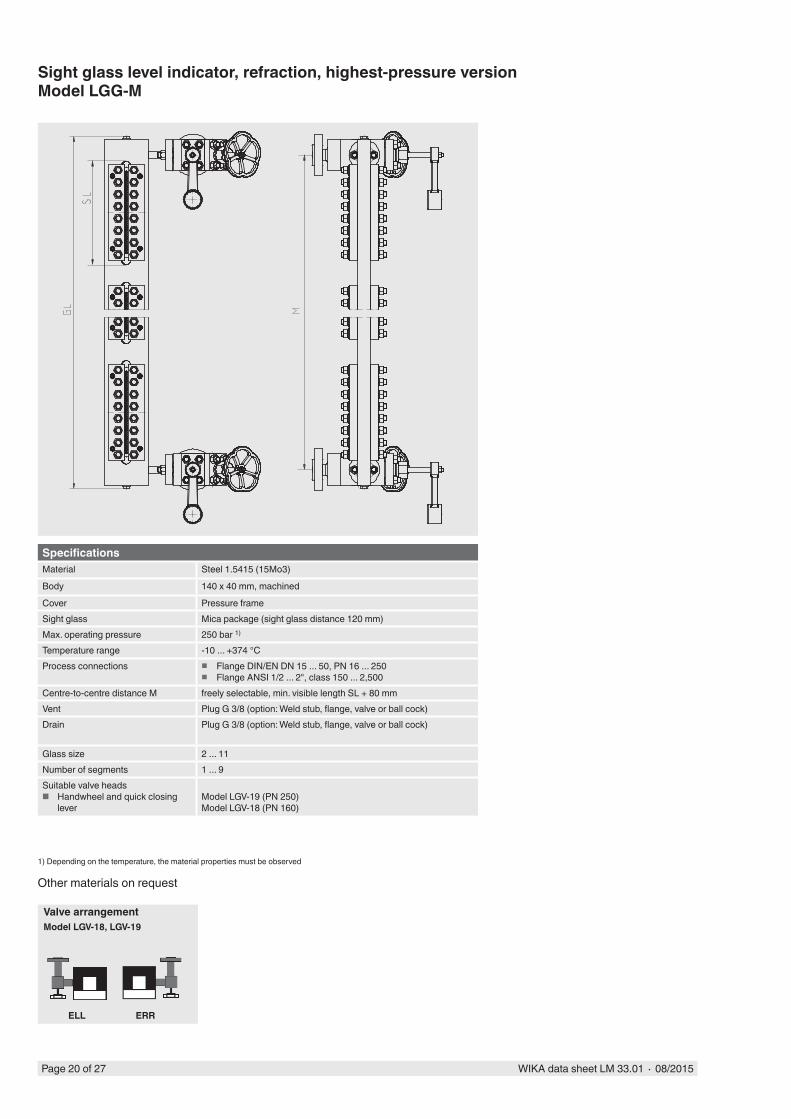
Sight glass level indicator, refraction, highest-pressure versionModel LGG-M
Other materials on request
SpecificationsMaterial Steel 1.5415 (15Mo3)
Body 140 x 40 mm, machined
Cover Pressure frameSight glass Mica package (sight glass distance 120 mm)Max. operating pressure 250 bar 1)
Temperature range -10 ... +374 °CProcess connections � Flange DIN/EN DN 15 ... 50, PN 16 ... 250
� Flange ANSI 1/2 ... 2", class 150 ... 2,500Centre-to-centre distance M freely selectable, min. visible length SL + 80 mmVent Plug G 3/8 (option: Weld stub, flange, valve or ball cock)Drain Plug G 3/8 (option: Weld stub, flange, valve or ball cock)
Glass size 2 ... 11Number of segments 1 ... 9Suitable valve heads
■ Handwheel and quick closing lever
Model LGV-19 (PN 250)Model LGV-18 (PN 160)
1) Depending on the temperature, the material properties must be observed
Valve arrangementModel LGV-18, LGV-19
ELL ERR
WIKA data sheet LM 33.01 ∙ 08/2015 Page 21 of 27
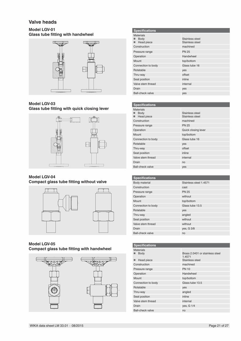
Model LGV-03Glass tube fitting with quick closing lever
Model LGV-04Compact glass tube fitting without valve
Model LGV-05Compact glass tube fitting with handwheel
Model LGV-01Glass tube fitting with handwheel
Valve headsSpecificationsMaterials
■ Body ■ Head piece
Stainless steelStainless steel
Construction machined
Pressure range PN 25Operation HandwheelMount top/bottomConnection to body Glass tube 16Rotatable yesThru-way offsetSeat position inlineValve stem thread internalDrain yesBall-check valve yes
SpecificationsMaterials
■ Body ■ Head piece
Stainless steelStainless steel
Construction machinedPressure range PN 25Operation Quick closing leverMount top/bottomConnection to body Glass tube 16Rotatable yesThru-way offsetSeat position inlineValve stem thread internalDrain noBall-check valve yes
SpecificationsBody material Stainless steel 1.4571Construction castPressure range PN 25Operation withoutMount top/bottomConnection to body Glass tube 13.5Rotatable yesThru-way angledSeat position withoutValve stem thread withoutDrain yes, G 3/8Ball-check valve no
SpecificationsMaterials
■ Body
■ Head piece
Brass 2.0401 or stainless steel 1.4571Stainless steel
Construction machinedPressure range PN 10Operation HandwheelMount top/bottomConnection to body Glass tube 13.5Rotatable yesThru-way angledSeat position inlineValve stem thread internalDrain yes, G 1/4Ball-check valve no
Page 22 of 27 WIKA data sheet LM 33.01 ∙ 08/2015
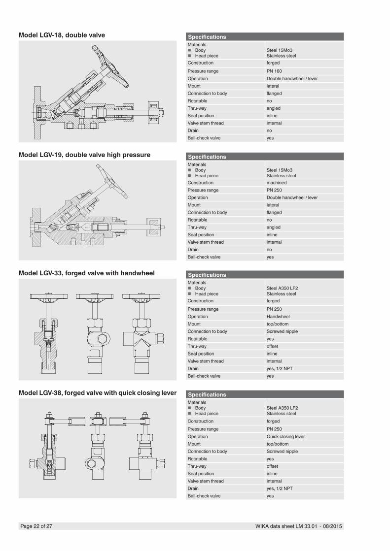
Model LGV-18, double valve SpecificationsMaterials
■ Body ■ Head piece
Steel 15Mo3Stainless steel
Construction forged
Pressure range PN 160Operation Double handwheel / leverMount lateralConnection to body flangedRotatable noThru-way angledSeat position inlineValve stem thread internalDrain noBall-check valve yes
Model LGV-19, double valve high pressure SpecificationsMaterials
■ Body ■ Head piece
Steel 15Mo3Stainless steel
Construction machinedPressure range PN 250Operation Double handwheel / leverMount lateralConnection to body flangedRotatable noThru-way angledSeat position inlineValve stem thread internalDrain noBall-check valve yes
Model LGV-33, forged valve with handwheel SpecificationsMaterials
■ Body ■ Head piece
Steel A350 LF2Stainless steel
Construction forged
Pressure range PN 250Operation HandwheelMount top/bottomConnection to body Screwed nippleRotatable yesThru-way offsetSeat position inlineValve stem thread internalDrain yes, 1/2 NPTBall-check valve yes
Model LGV-38, forged valve with quick closing lever SpecificationsMaterials
■ Body ■ Head piece
Steel A350 LF2Stainless steel
Construction forgedPressure range PN 250Operation Quick closing leverMount top/bottomConnection to body Screwed nippleRotatable yesThru-way offsetSeat position inlineValve stem thread internalDrain yes, 1/2 NPTBall-check valve yes
WIKA data sheet LM 33.01 ∙ 08/2015 Page 23 of 27
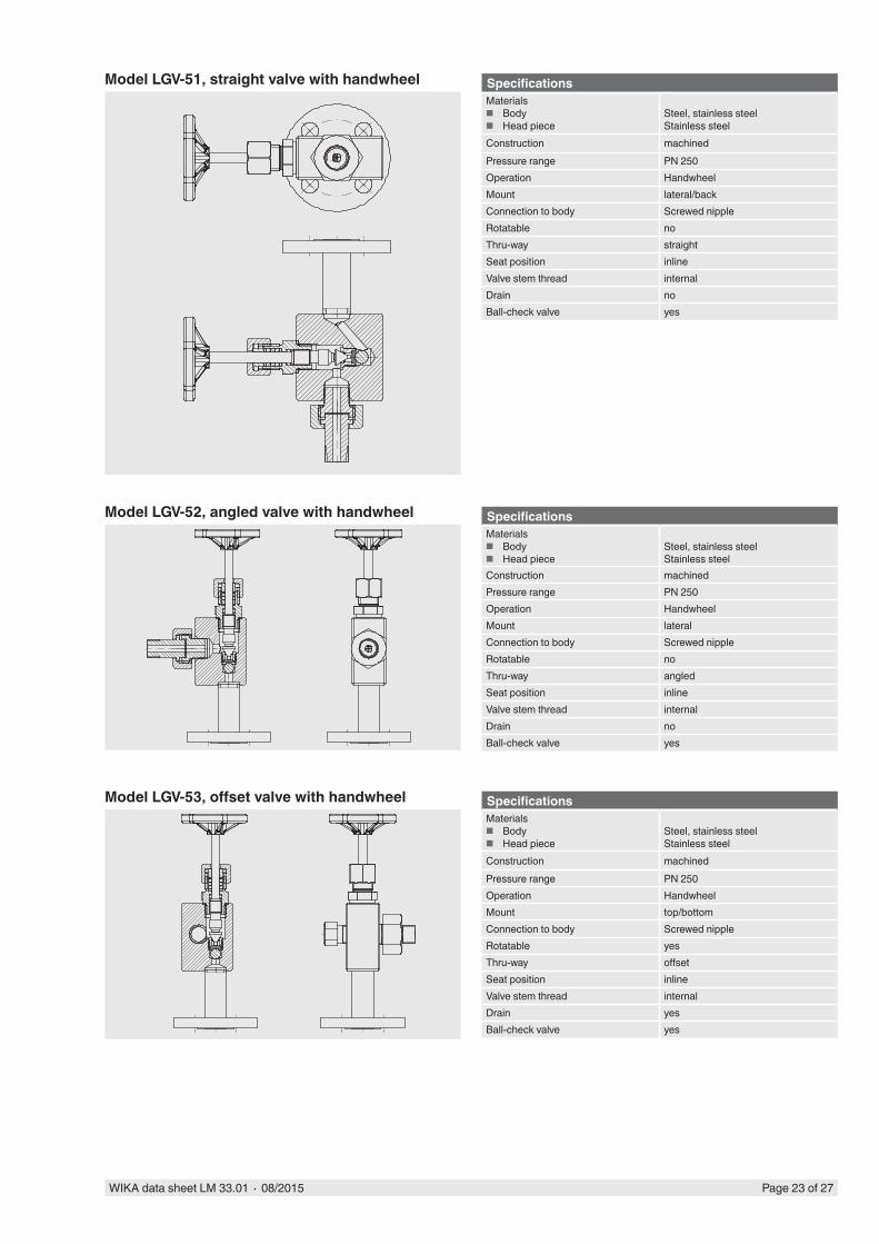
Model LGV-51, straight valve with handwheel SpecificationsMaterials
■ Body ■ Head piece
Steel, stainless steelStainless steel
Construction machinedPressure range PN 250Operation HandwheelMount lateral/backConnection to body Screwed nippleRotatable noThru-way straightSeat position inlineValve stem thread internalDrain noBall-check valve yes
Model LGV-52, angled valve with handwheel SpecificationsMaterials
■ Body ■ Head piece
Steel, stainless steelStainless steel
Construction machinedPressure range PN 250Operation HandwheelMount lateralConnection to body Screwed nippleRotatable noThru-way angledSeat position inlineValve stem thread internalDrain noBall-check valve yes
Model LGV-53, offset valve with handwheel SpecificationsMaterials
■ Body ■ Head piece
Steel, stainless steelStainless steel
Construction machinedPressure range PN 250Operation HandwheelMount top/bottomConnection to body Screwed nippleRotatable yesThru-way offsetSeat position inlineValve stem thread internalDrain yesBall-check valve yes
Page 24 of 27 WIKA data sheet LM 33.01 ∙ 08/2015
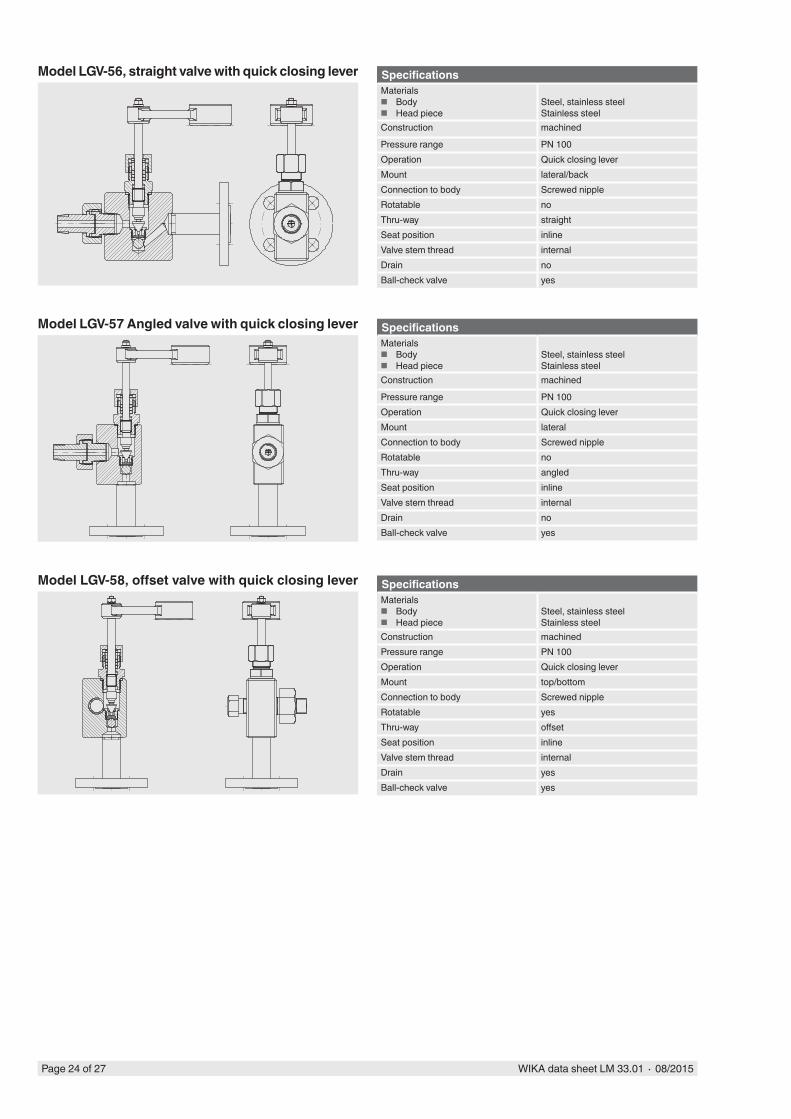
Model LGV-57 Angled valve with quick closing lever SpecificationsMaterials
■ Body ■ Head piece
Steel, stainless steelStainless steel
Construction machined
Pressure range PN 100Operation Quick closing leverMount lateralConnection to body Screwed nippleRotatable noThru-way angledSeat position inlineValve stem thread internalDrain noBall-check valve yes
Model LGV-58, offset valve with quick closing lever SpecificationsMaterials
■ Body ■ Head piece
Steel, stainless steelStainless steel
Construction machinedPressure range PN 100Operation Quick closing leverMount top/bottomConnection to body Screwed nippleRotatable yesThru-way offsetSeat position inlineValve stem thread internalDrain yesBall-check valve yes
Model LGV-56, straight valve with quick closing lever SpecificationsMaterials
■ Body ■ Head piece
Steel, stainless steelStainless steel
Construction machined
Pressure range PN 100Operation Quick closing leverMount lateral/backConnection to body Screwed nippleRotatable noThru-way straightSeat position inlineValve stem thread internalDrain noBall-check valve yes
WIKA data sheet LM 33.01 ∙ 08/2015 Page 25 of 27
Accessories
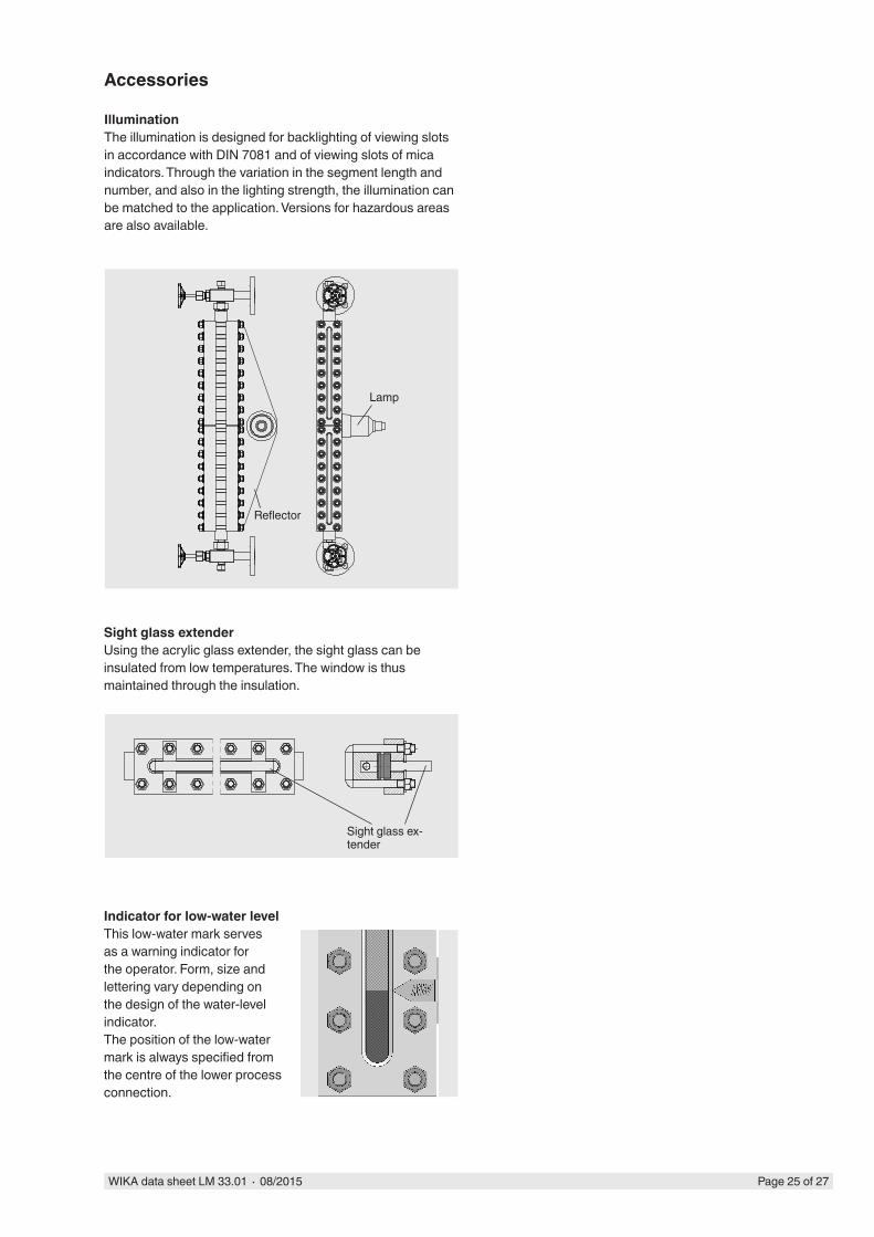
IlluminationThe illumination is designed for backlighting of viewing slots in accordance with DIN 7081 and of viewing slots of mica indicators. Through the variation in the segment length and number, and also in the lighting strength, the illumination can be matched to the application. Versions for hazardous areas are also available.
Sight glass extenderUsing the acrylic glass extender, the sight glass can be insulated from low temperatures. The window is thus maintained through the insulation.
Indicator for low-water levelThis low-water mark serves as a warning indicator for the operator. Form, size and lettering vary depending on the design of the water-level indicator.The position of the low-water mark is always specified from the centre of the lower process connection.
Lamp
Reflector
Sight glass ex-tender
Page 26 of 27 WIKA data sheet LM 33.01 ∙ 08/2015
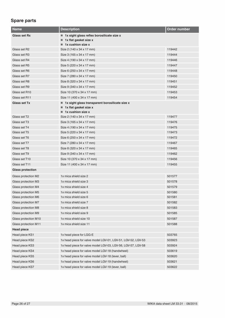
Name Description Order number
Glass set Rx ■ 1x sight glass reflex borosilicate size x ■ 1x flat gasket size x ■ 1x cushion size x
Glass set R2 Size 2 (140 x 34 x 17 mm) 119442Glass set R3 Size 3 (165 x 34 x 17 mm) 119444Glass set R4 Size 4 (190 x 34 x 17 mm) 119446Glass set R5 Size 5 (220 x 34 x 17 mm) 119447Glass set R6 Size 6 (250 x 34 x 17 mm) 119448Glass set R7 Size 7 (280 x 34 x 17 mm) 119450Glass set R8 Size 8 (320 x 34 x 17 mm) 119451Glass set R9 Size 9 (340 x 34 x 17 mm) 119452Glass set R10 Size 10 (370 x 34 x 17 mm) 119453Glass set R11 Size 11 (400 x 34 x 17 mm) 119454Glass set Tx ■ 1x sight glass transparent borosilicate size x
■ 1x flat gasket size x ■ 1x cushion size x
Glass set T2 Size 2 (140 x 34 x 17 mm) 119477Glass set T3 Size 3 (165 x 34 x 17 mm) 119476Glass set T4 Size 4 (190 x 34 x 17 mm) 119475Glass set T5 Size 5 (220 x 34 x 17 mm) 119473Glass set T6 Size 6 (250 x 34 x 17 mm) 119472Glass set T7 Size 7 (280 x 34 x 17 mm) 119467Glass set T8 Size 8 (320 x 34 x 17 mm) 119465Glass set T9 Size 9 (340 x 34 x 17 mm) 119462Glass set T10 Size 10 (370 x 34 x 17 mm) 119456Glass set T11 Size 11 (400 x 34 x 17 mm) 119455Glass protection
Glass protection M2 1x mica shield size 2 501577Glass protection M3 1x mica shield size 3 501578Glass protection M4 1x mica shield size 4 501579Glass protection M5 1x mica shield size 5 501580Glass protection M6 1x mica shield size 6 501581Glass protection M7 1x mica shield size 7 501582Glass protection M8 1x mica shield size 8 501583Glass protection M9 1x mica shield size 9 501585
Glass protection M10 1x mica shield size 10 501587Glass protection M11 1x mica shield size 11 501588Head pieceHead piece KS1 1x head piece for LGG-E 503765Head piece KS2 1x head piece for valve model LGV-01, LGV-51, LGV-52, LGV-53 503923Head piece KS3 1x head piece for valve model LGV-03, LGV-56, LGV-57, LGV-58 503924Head piece KS4 1x head piece for valve model LGV-18 (handwheel) 503619Head piece KS5 1x head piece for valve model LGV-18 (lever, ball) 503620Head piece KS6 1x head piece for valve model LGV-19 (handwheel) 503621Head piece KS7 1x head piece for valve model LGV-19 (lever, ball) 503622
Spare parts
WIKA Alexander Wiegand SE & Co. KGAlexander-Wiegand-Straße 3063911 Klingenberg/GermanyTel. +49 9372 132-0Fax +49 9372 [email protected]
WIKA data sheet LM 33.01 ∙ 08/2015 Page 27 of 27
08/2
015
EN
Ordering informationTo order the described product the order number (if available) is sufficient.
Alternatively:Model / Version / Process connection / Centre-to-centre distance / Valve type / Valve head arrangement / Process specifica-tions (operating temperature and pressure) / Options
© 2014 WIKA Alexander Wiegand SE & Co. KG, all rights reserved.The specifications given in this document represent the state of engineering at the time of publishing.We reserve the right to make modifications to the specifications and materials.


![u]N; tyf Enf=O=n]lgg - Marxists Internet Archive · u]N; tyf Enf=O=n]lgg - Marxists Internet Archive ... f](https://img.pdfslide.us/doc/110x75/5e083449c8d96950a56d317d/un-tyf-enfonlgg-marxists-internet-archive-un-tyf-enfonlgg-marxists.jpg)