Embed Size (px)
Citation preview
i
Siggraph Tutorial on Object and Constraint Paradigms for Graphics
Chapters 3 and 8
Edwin Blake Speakers: Edwin H. Blake Bjorn N. Freeman-Benson Chris Laffra Peter Wisskirchen
I Object Oriented Methods for Graphics (L) II Object-Oriented and Classical Approaches (W) III Models and Actors IV Introduction to Constraints (F) V Object-Oriented Graphics Systems (W) VI Object-Oriented Frameworks for Interaction and Graphics (L) VII Constraints, Objects, and Algorithms (F) VIII Advanced Techniques
ii
Abstract Object and Constraint Paradigms for Graphics
Object-oriented techniques are very appropriate for structuring complex designs in computer graphics. The characteristic requirements of graphics have prompted further developments of this approach. The course covers necessary concepts and the extensions needed for their application to graphics, as well as the implementations of these ideas.
There is a comparison of object-oriented and classical approaches to computer graphics. General techniques are demonstrated by tackling specific problems in graphics, interaction and animation. The solutions derived are interesting in their own right. The course shows how constraint-based techniques are a useful extension of object-oriented methods. Recent progress is assessed and highlights are presented.
This course will enable participants to design a graphical system using an object-oriented framework and constraint-based techniques. Practical examples are given to underpin the general guide-lines. Participants who are already familiar with object-oriented programming will learn of the extensions that are needed for the successful application of object-oriented techniques to graphics. Participants with less practical experience will become aware of the restrictions of current systems and the benefits the extended object-oriented approach has to offer.
The advances in object-oriented graphics presented at recent workshops on the subject will be incorporated in the lectures where appropriate. Participants will thus be introduced to important current topics of research and should be able to follow their progress in future.
This course is for computer graphics professionals who want state-of-the-art techniques for structuring complex graphics systems. It should also be useful for people who are dissatisfied with traditional programming techniques and are interested in new paradigms. It should also serve the needs of those familiar with object-oriented techniques who want to extend the basic framework for use in computer graphics — anyone who would attend both SIGGRAPH and OOPSLA.
A basic knowledge of programming and techniques in some area of graphics is required. Some exposure to object-oriented concepts will be helpful. This course will most benefit participants who are aware of problems with current methods for structuring graphics systems. It covers high-level ideas that are illustrated and motivated with practical examples.
iii
1.1. Speakers
Edwin H. Blake Centre for Mathematics and Computer Science (CWI) Senior Researcher (Interactive Systems Department)
Kruislaan 413 1098 SJ Amsterdam The Netherlands
Telephone: +31 20 5924009 Fax: +31 20 5924199 Email: [email protected]
Edwin Blake is a researcher in the Interactive Systems Department of the Centre for Mathematics and Computer Science (CWI) in Amsterdam, the Netherlands. He is active in designing new architectures for interactive graphics systems. He is also investigating the applicability of object-oriented programming to computer graphics and animation. He received his Ph.D. in 1989 from Queen Mary College, University of London. The work was on adaptive data structuring for computer animation.
He is a joint organiser (with Laffra) of the second Eurographics workshop on Object-Oriented Graphics to be held in 1991. He presented the state of the art report on Object-Oriented Graphics at Eurographics’90.
Bjorn N. Freeman-Benson University of Washington
Dept of Computer Science & Engineering FR-35 University of Washington Seattle, WA, 98195 USA
Telephone: +1 206 543-4226 (office) +1 206 543-1695 (main #)Fax: +1 206 543-2969 Email: [email protected]
Bjorn Freeman-Benson is finishing his Ph.D. at the University of Washington. His research areas are programming languages and user interfaces, and his thesis topic is an integration of the imperative object-oriented and the declarative constraint programming paradigms to support building interactive graphical user interfaces. He is implementing a language based on this integration. The language, Kaleidoscope, is described in his 1990 ECOOP/OOPSLA paper. Other related research at the University of Washington includes hierarchical constraint logic programming and constraint-based tools for building user interfaces, such as ThingLab II.
Chris Laffra SERC — Software Engineering Research Center
P.O.Box 424 3500 AK Utrecht The Netherlands
Telephone: +31 30 322640 Fax: +31 30 341249 Email: [email protected]
Chris Laffra is completing a Ph.D. at Leiden University, The Netherlands. His research in object-oriented languages shows their applicability to user-interface design. He has concluded an implementation of the concurrent object-oriented language Procol of which he is co-designer [see paper OOPSLA’89]. He is also a co-author of an object-oriented framework for interaction based
iv
on delegation instead of inheritance [see paper First Eurographics Workshop on Object-Oriented Graphics, Königswinter, 1990].
He is currently working for the SERC, Software Engineering Research Centre, in Utrecht, The Netherlands. Related research performed at SERC includes DIGIS, a direct manipulation tool to design an interactive direct-manipulation application interactively. He is a joint organizer (with Blake) of the Second Eurographics Workshop on Object-Oriented Graphics.
Peter Wisskirchen Gesellschaft für Mathematik und Datenverarbeitung Director of Institute for Applied Information Technology
Schloss Birlinghoven P. O. Box 1240 D-5205 St. Augustin 1 Germany
Telephone: +49 2241 142315 Fax: +49 2241 142618 Email: [email protected]
Peter Wisskirchen is a director of the Institute for Applied Information Technology of the GMD (German National Research Center for Computer Science) in St. Augustin, near Bonn, Germany. His research interests include computer graphics, generalized man-machine communication, and integrated office information systems. Wisskirchen is the chairman of the special interest group in Graphics Systems within the German scientific and professional computing organization, “Gesellschaft für Informatik” (GI). He also coordinates the computer graphics activities of Germany’s large-scale national research centres (AGF). Wisskirchen is one of the pioneers in the definition of the computer graphics standard GKS. He was a member of the first editorial subgroup, which produced the early specifications for GKS. Wisskirchen received his Ph.D. in Mathematics from the University of Bonn in 1969.
In his book “Object-Oriented Graphics — From GKS and PHIGS to object-oriented Systems” (Springer Verlag, 1990) Wisskirchen shows the potential of object-oriented system, and he builds a bridge between traditional systems and the object-oriented approach.

v
2. Preface
I–1
3. I Object-Oriented Methods for Graphics. 1. Complexity
• geometric detail and structure • object transformations • dependencies / relations • user interface • large systems
2. Why Object-Oriented Methods for Graphics? • complexity • abstraction • intuitive approach ♦ • concurrency • flexibility
3. Object-Oriented Graphics • object-oriented methods • object-oriented user interfaces • “object-oriented”
4. History of Object-Oriented • Simula • Smalltalk, Objective C, C++, Eiffel • Actors
5. Object-Oriented Methods • data abstraction (encapsulation) • class • inheritance / delegation • messages
6. Abstract Data Types (Encapsulation) • data • messages • protocol • class is ADT description of instance
7. Classes and Inheritance • inheritance hierarchy — subclass is specialization of superclass • multiple inheritance • code reuse vs. type relationships
I–2
8. Delegation • forwarding messages to delegates • prototypes • delegation is dynamic and flexible
9. Concurrency • events happen at same time • natural problem decomposition • parallel hardware • Actors
10. Object-Oriented Features for Graphics • desirable ? • important ? • consistent and complete ? • orthogonal ?
11. Constraints • relationships between graphics objects • constraint embodies: • description = declarative, rule • methods = procedural • problems with encapsulation [Comments of the slides for session II]
1. Complexity The essence of our tutorial! How do we solve the complexity problem imposed by graphics
systems? Traditional system focus on part-whole hierarchies, and not on inter-“object” relationships. Naming of objects is indirect, in OO systems it is not. Principle of “Hidden kernel” (functionality, portability, device independence, optimization). Access to data-structure is indirect and forms gap between ‘mental model’ and implementation. Interaction and direct manipulation is difficult.
2. Why Object-Oriented Methods for Graphics? Object-oriented techniques help reduce complexity by localization of this complexity. They
provide abstraction by offering abstract data types, and object composition into part-whole hierarchies. But, the most important point scored by OO techniques is that they are natural and intuitive. Every item in our graphic system, be it a feature being modelled in a CAD system, or a rectangle in drawing editor, they all are direct candidates to be promoted into *objects*. They have their own representation, attributes, behavior, and way of manipulation. They can be composed into other objects to form a higher level component.
I–3
3. Object-Oriented Graphics Diffentiate on different kinds of OO-ness. (i) With OO methods we mean those concepts, such
as encapsulation, classes, inheritance an so on. These can be implemented in an OO language, but can also be provided in a non-OO language. (ii) OO user interfaces that allow direct manipulation on “objects” on the screen, using icons and some pointing device. Implementation can be done in conventional language, but is more naturally done by using an OO language. (iii) Compare MacDraw with MacPaint.
4. History of Object-Oriented Simula is the core of OO-ness. Interesting to note that Simula is a language that was designed
to support the development of simulation software. If we look at computer graphics, in fact everything runs down to being a simulation; Rendering, CAD, animation. If we apply graphics we are generally ‘simulating’ the real world, precisely for which purpose Simula was invented.
Then came Smalltalk, made OO popular in research environments. Graphics kernel, nice user interface, windows, MVC. Slow in the beginning, nowadays more efficient implementations. Objective-C (NeXT, ICPak), C++, and Eiffel made OO popular in the applied areas.
Actors is language family developed from AI. Concurrency. Some claim that Actors are not OO, but object based; is beyond scope of course. See Wegner, etc. Importance is influence it has had on concurrency research in OO languages.
5. Object-Oriented Methods No deep intoduction into OO concept. Only those that are relevant to graphics. See literature
for more info. Emphasize ADT/encapsulation and inheritance as a flexible construct to enhance OO graphics kernels.
6. Abstract Data Types (Encapsulation) Encapsulation of attributes accessed by calling methods = sending messages.
7. Classes and Inheritance Inheritance defines IS-A relationships. Is different from part-whole tree. Emphasize on
differences between code reuse (implementation aspect) and type relationships (is a modeling aspect).
8. Delegation Show delegation is an alternative to inheritance (Liebermann, Stein). Delegation is along the
lines of part-whole hierarchies, with object delegation responsibilies to specially created delegates which form a part of their extended identity. Delegates can be distributed, which is not possible when using inheritance. Compare with 1 person leading a company, knowing how to type letters, make products, sell them, make luch, etc. On the other hand the company could consist of 1 manager, and many delegates working for him. If an external contact places some order, the manager will set the correct employee to work for him. He might even switch employees, while the company stays in the market.
9. Concurrency Yes, concurrency is natural, real live is concurrent in many facets. Concurrency needs to be
taken with into the design of an OO graphics kernel right from the start. Not as an after thought!
I–4
10. Object-Oriented Features for Graphics For each OO concept that we want to add to the kernel, we have to ask some questions.
11. Constraints Constraint form the glue to combine the building blocks offered by the OO approach. OO is
good to make abstractions, part-whole trees, specializations, and interactive behavior. Interobject relationships (especially geometric relations) are hard to maintain in a imperative environment such as OO systems. More appropriate is the declarative approach offered by constraints. They define *what* is to be computed, and not *how* it is to be computed. Special care has to be given to the impedance mismatch between encapsulation and constraints.
II–1
4. II Object-Oriented and Classical Approaches. 1. Short description:
Object-Oriented approaches are compared to classical graphics kernel systems, in particular the graphics standards GKS and PHIGS. The classical procedure oriented layer model is contrasted to object-oriented class libraries. It is shown how graphics output primitives organized as instances of their own class makes programming easier and better comprehensable. First ideas of how to use inheritance for graphics are summarized.
2. Functionaltiy and goals of the standards GKS&PHIGS
3. Characteristica of current object-oriented kernels
4. Strategies to assign attributes
5. Class library vers. layer model
6. Editing of output primitives
7. Use of inheritance
8. Mutual communication between kernel and application by using call-backs
III–1
5. III Models and Actors. Edwin Blake. This section shows how an object-oriented approach helps with some of the typical problems
in programming computer graphics and animation systems: structures for building, positioning and controlling three-dimensional objects. The mechanism should provide an appropriate metaphor for image synthesizers and animation programmers. The essential idea is to manage complexity by hiding irrelevant detail and by re-using code and concepts whenever possible.
The object-oriented approach simplifies the task of designing complex systems. When we design a system we consider the classes and design class and part hierarchies.
5.1. 1. Modelling Three-Dimensional Physical Objects. In modelling one obviously, and correctly, expects the objects in a three-dimensional
simulated world to correspond to the objects of the object-oriented system. There is in fact a very good match. In animation systems the moving objects are often called actors. These actors are objects which can interact with their simulated environment and maintain their identity as the animation proceeds.
Multiple actors of the same type are, in object-oriented programming terms, instances of the same class. The individual objects are given their unique identity by the attributes stored as part of their internal state. Identically modelled pine trees still differ by their position — which is part of their state.
A number of the ideas for modelling objects are based on ThingLab. This was an early successful research application written in Smalltalk (Smalltalk-76) [1;2;3;4]. It is a system for simulating physical objects (e.g., geometric shapes, bridges, electrical circuits, documents, calculators). In ThingLab, objects consist of parts. Multiple class inheritance hierarchies, and part-whole hierarchies are used to describe the objects and their interrelations. Parts are referred to symbolically by means of paths that name the nodes to be visited in proceeding down the part hierarchy.
The rest of this section will be an explanation of how class inheritance hierarchies and part-whole hierarchies are used in modelling. During the design we are frequently intent on producing so-called “abstract” superclasses, these classes are intended to have the general protocol of messages for a problem but perhaps not the specific functionality. The full functionality being provided by subclasses which are specified at a later stage.
III–2
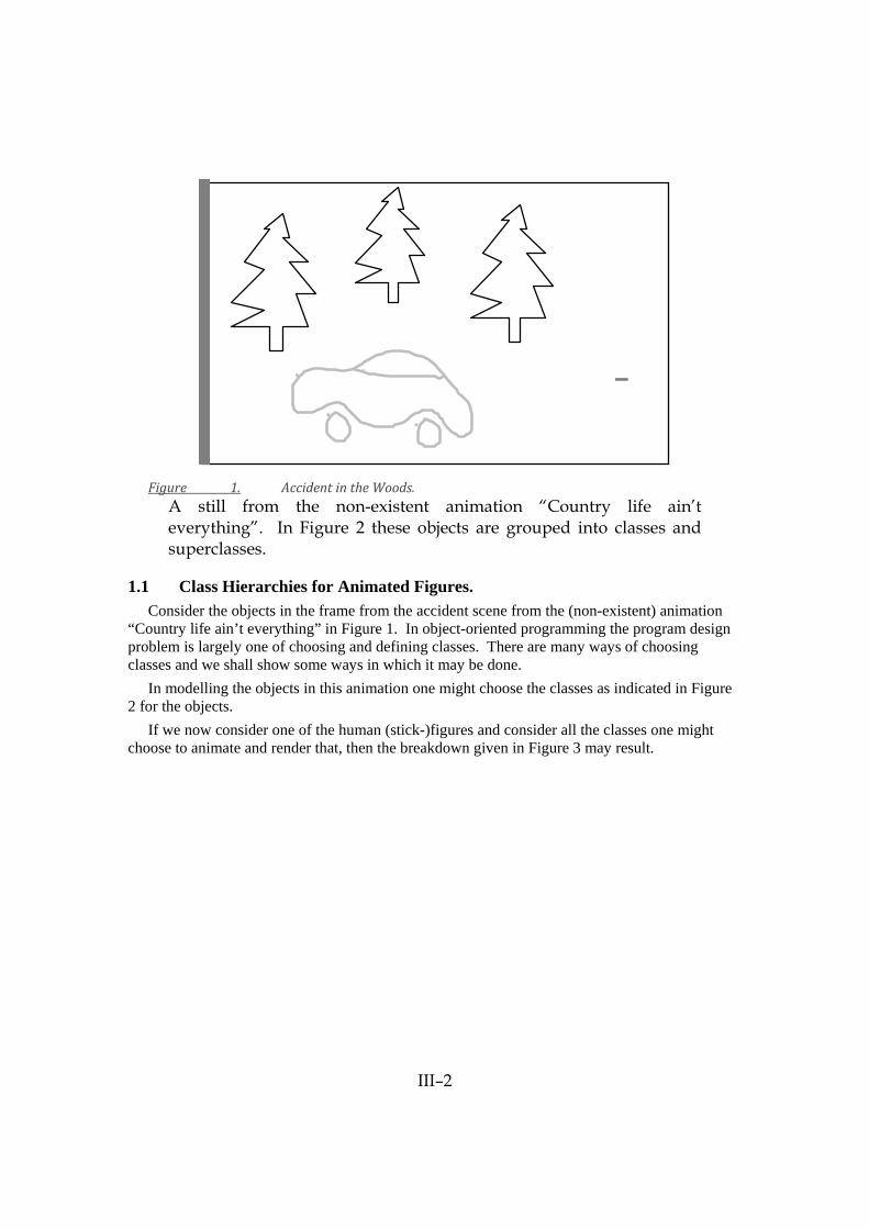
Figure 1. Accident in the Woods.
A still from the non-existent animation “Country life ain’t everything”. In Figure 2 these objects are grouped into classes and superclasses.
1.1 Class Hierarchies for Animated Figures. Consider the objects in the frame from the accident scene from the (non-existent) animation
“Country life ain’t everything” in Figure 1. In object-oriented programming the program design problem is largely one of choosing and defining classes. There are many ways of choosing classes and we shall show some ways in which it may be done.
In modelling the objects in this animation one might choose the classes as indicated in Figure 2 for the objects.
If we now consider one of the human (stick-)figures and consider all the classes one might choose to animate and render that, then the breakdown given in Figure 3 may result.

III–3
Movable Objects
Visible Objects
Figure 2. Classes involved in “Accident in the Woods”.
The rounded boxes represent classes of objects. Concrete classes show the instances of that class which are used. Abstract classes, of which instances are never created, are indicated by their name.
PositionableObject
ObjectWithParts
Camera
Actor
ActorCollection
Arm BigToe Chest Digit Foot ForeArm Hand Leg LowerLeg MiddlePhalanx Person Thumb
SimpleActor
NohActor Figure 3. The subclass hierarchy of the class ObjectWithParts.
These classes are used to model a stick figure.

III–4
The knowledge required to implement moving figures is factored over a hierarchy of classes. As usual the top level class in our sub-hierarchy for creating actors is the most general, abstract, and simplest. This is the class ObjectWithParts; it confers the ability on objects to consist of parts. Subclasses of ObjectWithParts will inherit its message protocol, which is the set of messages it can understand, along with any methods implemented for executing the messages. Processing is carried on by instances of classes, but no instances of this class are created since it is rather abstract.
The next subclass, PositionableObject, which is also an abstract class, provides the six degrees of freedom of objects in space: position and orientation. The required transformations are implemented by instances of the class RevoluteJoint which in turn uses the class Quaternion. Any subclass of PositionableObject will be able to implement a modelling hierarchy consisting of subassemblies and transformations.
Instances of the subclass Camera are used to render other actors. The class Actor confers the ability for an object to have a visible appearance but is itself too general to be concrete. The appearance of an Actor depends on the class of object in its appearance ‘slot’ or instance variable. For a stick figure this is an instance of the class Stick, but it could be a more complicated appearance. Instances of Stick know how to interact with an instance of Camera for rendering and this is all that would be required from more complicated appearances.
The subclasses of Actor are the actual parts of a figure. Because a SimpleActor is a terminal node in the object hierarchy it has no parts and its inherited capability for parts is disabled.
Multiple Inheritance. In a number of cases one would like to inherit characteristics from multiple super classes. For
example, in the first hierarchy (Figure 2) “Movable Objects” are a subclass of “Visible Objects”, while in the second (Figure 3) “Camera” is a PositionableObject (= Movable Object) but is not normally a Visible Object. Thus visibility should actually be inherited independently from mobility: a case for allowing a class to inherit traits independently from a pool of possibilities.
Another example is the class of ActorCollection in Figure 3 which combines the features of an Actor with those of a collection of objects. Object-oriented languages often provide inadequate support for multiple inheritance and one tends to opt for a single hierarchy and use single inheritance .
1.2 Part-Whole Hierarchies for Physical Objects. Using an object-oriented approach to modelling has the advantage that the parts which an
object possesses need not actually be represented as such in the object. The internal implementation of the object is hidden behind the object’s interface protocol. The only requirement is that the object respond correctly to messages which address the part. This allows great freedom for dealing with special cases. A particular object is free to possess phantom appendages which represent anomalous detail structures that appear occasionally.
When an object is modelled we get both a class hierarchy and a different kind of hierarchy: the part-whole or modelling hierarchy. A modelling hierarchy records the way complex objects are built up out of simpler parts. When animating natural figures consisting of rigid limbs connected by joints it is usual to model a figure as a tree of dependent parts (this is in general not possible for artificial objects where mechanical feedback loops necessitate more complicated structures).
The human body can be modelled as a tree of parts, the root of which is the torso and the parts are the chest, head, upper arm, forearm, hands, thigh, lower leg, foot, etc (Figure 4).

III–5
littleToe (Digit)
fourthToe (Digit)
middleToe (Digit)
secondToe (Digit)
bigToe (BigToe)
lowerLeg (LowerLeg)
leftLeg (LeftLeg)
foot (Foot)
middlePhalanx (MiddlePhalanx)
middlePhalanx (MiddlePhalanx)
middlePhalanx (MiddlePhalanx)
middlePhalanx (MiddlePhalanx)
distalPhalanx (SimpleActor)
distalPhalanx (SimpleActor)
distalPhalanx (SimpleActor)
distalPhalanx (SimpleActor)
distalPhalanx (SimpleActor)
Figure 4. The part hierarchy of the left leg of a stick figure. The top name in each box is the part name and the bottom name (in parentheses) is the class to which the part belongs. All the classes are a kind of (i.e., subclass of) Actor.
Deeper into parts and wholes. Part-whole analysis is crucial in engineering and technology. Objects are often described as a
hierarchy of assemblies and subassemblies. Parts are also met in those branches of computation where physical objects are represented, for example, artificial intelligence and computer graphics.
Standard texts on computer graphics discuss “Modelling and the Object Hierarchy”. PHIGS (Programmer’s Hierarchical Interactive Graphics System) and GEO++ organize objects in a structure or in a group hierarchy (see Chapter V). Both structure hierarchy and object hierarchy, as used above, are equivalent to a part hierarchy. PHIGS also has the concept of inheritance on a part hierarchy where attributes of the whole are inherited by the parts. E.g., the legs of the table could inherit the colour of the whole.
We should adopt the policy that information is stored in the part hierarchy at its corresponding logical level. Information about the whole is not stored in the parts, information about the parts

III–6
which is not modified by the whole remains with the parts. Ideally the whole knows the parts but the parts do not know of the whole.
But, Smalltalk and many other object-oriented languages fail to provide the facility to describe objects in terms of their parts. Or more accurately, when we want to model objects consisting of parts in Smalltalk, and many other object-oriented languages, we are confronted with a dilemma: either sacrifice the data encapsulation properties of the language or utterly flatten the part-whole hierarchy. For a more complete discussion of these issues and ways of dealing with them see [5], or alternatively [6].
1.3 More Parts and Classes for a Graphics System. Up to now we have been talking in terms of building up physical objects. Parts of course
occur not just in models of physical objects but throughout a program (Figure 5). If we wrote a simple animation system we would first split it into a user-interface part and the animation production system proper. The animated world would consist of three basic types of objects and numerous supporting objects (class names are indicated by capital letters):
Stage. The global object which contains all other objects as parts or sub-parts. An important part of the Stage is the Clock. There is only one Stage per animation. The Clock owns a list of all active objects, we could call them the list of Frenetics.
Actor. An actor is the basic unit of animation. The actors have a Script which is the sequence of actions which they execute. They have an Appearance which determines how they will look on a display. There can be any number of Actors in the world. Appearances exist for every Camera.
Camera. The camera takes the Appearance of an Actor and renders it on a Segment. The Segments are submitted to a Window to be displayed. Although there can be a number of Cameras the current user interface only allows one to be set up. The Camera owns a number of renderers, corresponding to such different algorithms as might be required.

III–7
Stage
Clock
Cameras
Window
Actors
CostumeScripts
List: Segments
List: Frenetics
List: Appearances
Quick Perfect
List: Renderers
Figure 5. The part hierarchy of selected classes in the animation system.
All objects which can change over time are subclasses of the abstract superclass
KineticObject. So the Stage, Actors and Cameras are all subclasses of KineticObject. We shall emphasize that we need to be able to use many underlying representations together in
a single animation sequence (see also Section 3, below). However we can reduce the full load of rendering an Actor by only passing relevant information about its appearance at a particular instant in time. This relevant information is encapsulated in the class Appearance (see Figure 6). The Appearance is a very important kind of object since it is part of a mechanism which frees us from having to rely on a single common primitive for all our representations. An Appearance is an abstract superclass, the real task of interpreting the way an Actor looks to a Segment is performed by its subclasses.

III–8
Moving Actor Camera Frames
Appearance: Captures the changing Actor for the Camera, frame by frame.
Figure 6. The Appearance of an Actor mediates between the Camera and the Actor.
5.2. 2. Making the Models Move. There are two aspects to modelling animated figures: producing computer representations
which allow movement and controlling that movement. The problem of controlling figure movements so that they appear realistic is an area of active research to which answers are only now appearing. In developing our chosen representation we shall be very concerned with providing an underlying mechanism which allows constraints on movement to be handled elegantly.
At the simplest level we can regard people and animals as being composed of limbs connected by revolute joints. Each part of the hierarchical representation of an object has its own changing local coordinate system. In animation and rendering these coordinate systems have to be related to one another and to the world coordinate system.
Animated figures and robots are governed by constraints on their allowed movements. Computer animators note the need for abstraction as a way of dealing with their rather difficult problem. Zeltzer points out how a human figure can be modelled as a tree structure of joints and parts. The parts are embedded in a generalization lattice of attributes, this lattice being supplied by some sort of multiple class inheritance hierarchy (in the object-oriented sense) [7]. He emphasizes that the complex modelled environment of an animated object has to be structured in some way which allows rapid testing for the proximity of objects.
2.1 Coordinate Transformations. Coordinate transformations play a vital role in computer graphics and animation. Scene
composition, rendering and motion would be impossible without them. Each object is modelled in its own coordinate space and is placed in its correct position
relative to other objects in the environment by means of its own coordinate transformation. The camera is similarly positioned in the modelled environment. To render three-dimensional models of objects on the display they have to be transformed into the camera coordinate space and then

III–9
projected by a perspective transformation. The movement of rigid objects is achieved by altering their coordinate transformations.
Each part of the hierarchical representation of an object has its own changing local coordinate system (Figure 7). In animation and rendering these coordinate systems have to be related to one another and to the world coordinate system.
= direction of z-axis.
1 — upper leg
2 — lower leg
3 — foot
x
y
y
xy
x Figure 7. The Hierarchy of Local Coordinate Systems.
This particular hierarchy arises when modelling the left leg of a stick figure. Each limb has its own local coordinate system.
The most general motion of a rigid body in the world coordinate system can be described as the combination of a translation of a fixed point in the object combined with a rotation about that point. The most general motion if one point is fixed is just rotation. Rotations are thus the most important transformation when implementing a system of localized coordinates for an animal’s limbs (or robot’s for that matter).
The standard formalism for 3-D computer graphics has tended to be homogeneous coordinates. Hamilton’s quaternions, although rather neglected since the turn of the century [8: “musty mathematics”], make a computationally efficient formalism which is also easy to understand. Compared to homogeneous transformation matrices quaternions have fewer redundant terms [9].
Each limb of the modelled figure has a local transformation quaternion (actually unit quaternion) which specifies its rotation with respect to the coordinate system of the limb to which it is attached. It also has a quaternion (actually a vector) which specifies its position relative to the origin of that coordinate system. This vector does not change for most limbs, only those which form the root of the hierarchy of coordinates reflect the changing translation of the actor as a whole. The synthetic camera requires a similar pair of quaternions. Perspective projection is achieved by bringing all objects into the camera coordinate system and then dividing by the distance along the viewing direction (invariably the z-axis coordinate).

III–10
2.2 Quaternions. Hamilton’s quaternions were introduced above as a way of representing coordinate
transformations. Quaternions consist of a scalar part and a three-dimensional vector part [10, 11, 12]. Those with the same unit vector part are isomorphic to complex numbers. Quaternion multiplication combines scalar and vector multiplication and is non-commutative in general. The famous formula discovered by Hamilton in 1843 shows the scalar result of multiplying the unit vectors:
i2 = j2 = k2 = –1
Quaternions represent rotations in terms of the axis of rotation and the angle about that axis. The effect of applying a quaternion is far easier to visualize than the more common Euler angles. Quaternions represent both the operands (vectors) and operators (rotations and translations) uniformly. Rotations can be combined by multiplying the quaternion representations. Quaternions provide a uniform representation of operators and operands; a vector can simply be regarded (and implemented) as a quaternion with a zero scalar term.
In order to illustrate the use of quaternions for rotation consider two unit vectors (u and v) with a common origin (see Figure 8). Let Q be the quaternion which represents the rotation from u to v. Then we can write:
Q = – v u
Q = cos θ2 + sin
θ2 ⊇ n
where n is the axis of rotation. The result of applying the rotation Q to the vector u is then v. That is:
v = Q u Q -1
= Q appliedTo: u
The details of these manipulations can be found in the references given for those who are interested.

III–11
Axis of Rotation
u
v
θ
Figure 8. Two unit vectors u and v with a common origin.
The shaded ellipse indicates their common plane, with the axis of rotation perpendicular to the plane. The angle between them is θ.
2.3 Message Passing and Polymorphism. Polymorphism can be used in a number of senses; the meaning is usually that a single external
operation can be applied to a variety of underlying types. For example: conventional typed programming languages allow the parameters of functions to have only one type. If this idea was strictly applied then addition would require a different function for each type of number and generalized routines would be impossible. Examples of simple polymorphic arithmetic messages are: 2 + 3. "Send the message '+' to the SmallInteger 2 with parameter 3" 5 * 3.5. "Send '*' to the SmallInteger 5 with the Float parameter 3.5" 2.7 + (1/3) "Send '+' to the Float 2.7 with the Fraction parameter (1/3)"
Polymorphic languages allow for the same functions to accept many different parameter types.
In object-oriented languages the same messages can be sent to a number of different classes and the messages can have any type of argument. Unlike procedure calls, messages sending allows polymorphism without the requiring constant checking of parameter types [13]. The existence of class hierarchies must entail a certain polymorphism if related but distinct classes are to understand the same messages.
The conceptual power of inheritance hierarchies derives, at least partly, from the way in which they allow automatic but controlled polymorphism for all subclasses. One largely knows the behaviour of an object if one knows the behaviour of its superclass.
Having polymorphic messages makes it possible to program by extending the language with new types. For example, it was very easy to add a new class of number, namely quaternions, to Smalltalk. These quaternions understand exactly the same messages, for multiplication, addition, square root, and so forth, as other numbers. Smalltalk can be said to exhibit “true” polymorphism because all objects are uniformly represented and can exhibit uniform behaviour without coercion or explicit type checking.

III–12
C++ does not use message lookup for procedure calls and is statically typed, but it does allow operator overloading, i.e., the same operator can have a number of different, but predetermined, types of arguments. Quaternions can be implemented just as elegantly as with Smalltalk.
2.4 Adding Quaternions to Smalltalk. The inherent polymorphism of messages (or overloading of operators) in Smalltalk allows
easy and elegant implementation. The normal arithmetic messages can be implemented for quaternions; combined with a few
coercion messages that is really all that is required to add quaternions as a subclass of numbers. Quaternions then become fully integrated in an extended system-wide concept of Number.
Number
Float IntegerFraction
LargeNegativeInteger LargePositiveInteger SmallInteger
Quaternion
Figure 9. The Numerical Classes of Smalltalk showing the addition of the new class
“Quaternion” in the hierarchy.
We define Quaternions to have four instance variables, called “alpha” for the scalar part and “beta, gamma, delta” for the vector part. We provide all the required messages. Now if we implement quaternions as a subclass of Number then we first implement the normal arithmetic messages. We also need specific methods, for example, to access the various instance variables.

III–13
class Quaternion
superclass Number
instance variable names
accessing
i ↑betaj ↑gammak ↑deltascalar ↑alpha
alphabetagammadelta
Figure 10. Class definition of Quaternion.
We also need methods to implement the arithmetic messages which all subclasses of Number
have to understand. Here are some examples: Quaternion methodsFor: 'arithmetic' * aQuat "The multiplication rule, where the quaternions Q1 and Q2 are written as (s1, v1) and (s2, v2) in terms of scalar and vector parts, is Q1 o Q2 = (s1s2 - v1.v2 + s1v2 + s2v1 + v1 x v2) " | a tempI tempJ tempK| a ♦ aQuat scalar. tempI ♦ aQuat i. tempJ ♦ aQuat j. tempK ♦ aQuat k. ⎯Quaternion new: alpha * a - (beta * tempI) - (gamma * tempJ) - (delta * tempK) i: alpha * tempI + (a * beta) + (gamma * tempK) - (delta * tempJ) j: alpha * tempJ + (a * gamma) - (beta * tempK) + (delta * tempI) k: alpha * tempK + (a * delta) + (beta * tempJ) - (gamma * tempI) + aQuat ⎯Quaternion new: alpha + aQuat scalar i: beta + aQuat i j: gamma + aQuat j k: delta + aQuat k

III–14
Naturally many more methods have to be defined. The above are just examples.
Figure 11. Moving a Foot.
The new instance of Person is assigned to the variable ‘joe’. Joe is asked to forward messages to its right foot using a non-standard compound message [14]. The request is to replace the orientation Quaternion by one which has been rotated by 40 degrees about a vector along the y-axis. Notice that the familiar multiplication message “*” is also understood by Quaternions.
A minor complication is having to represent translation and rotation as separate transformations. Once again one can simply define a new class which incorporates both and the rest of the system need never know of the true implementation.
For greater efficiency, unit quaternions, which are used for rotation transformations, are given special treatment. This is quite easy in Smalltalk and is transparent to the user. It is analogous to the way small integers are treated in the standard system. Unit quaternions are declared as a subclass of quaternions.

III–15
The general messages are then handled by the superclass but specialized messages and more efficient implementations are dealt with by the subclass. For example, the inverse of a unit quaternion can be found without recourse to division and so this message is re-implemented in the subclass.
2.5 Adding Quaternions to C++. In many practical situations C++ is used because it offers advantages of computational
efficiency over Smalltalk. Like Smalltalk classes and inheritance hierarchies can be defined. Compared to C type checking is improved, and inline functions can be defined for greater efficiency.
In general the polymorphism of Smalltalk is provided via three mechanisms in C++:
Operator Overloading. This means that the same message with different types (or classes) of parameters can be sent to an object provided that all the type information is known at compile time.
Overriding the methods defined by the superclass in the subclass. This mechanism can be used whenever all the types can be determined at compile time.
Virtual Functions. At run-time a message may be sent to a pointer to an object whose class is unknown, provided that the unknown object belongs to a class for which the particular message has been declared “virtual”. Such classes must all belong to the same inheritance tree.
Except for virtual functions then, C++ lacks dynamic binding. In the case of quaternions the lack of dynamic binding does not matter greatly. Dynamic binding obviates the need for re-linking when the underlying representation of a type is changed. It is in the nature of a number system like quaternions that the implementation and messages understood does not change very often, although new optimizations may occasionally be introduced.
Dynamic binding also allows a particular place holder (variable name) to contain a number of different types of objects. The binding is made at run time when the variable has been instantiated. Quaternions can reasonably be interchanged only with scalars and vectors and for such a limited set of possibilities coercion rules can be drawn up which the C++ compiler will then invoke automatically. It has generally been the case that the types of objects used in arithmetic can be determined at compile time.
The use of automatic coercion does have some hidden snags. Unless one is careful a lot of conversion can happen from unit quaternions to quaternions (this is cheap) and then back again (which is expensive since it involves division and square root calculation).
For a comparison with Smalltalk we give some examples of code for implementing Quaternions in C++.
Classes are defined almost like structures in C (or records in Pascal). Except that now both data and functions are included in the class. Unlike Smalltalk C++ is much stricter in enforcing data encapsulation: if a method or variable is not declared ‘public’ then it may be accessed from the outside. Generally one first declares the instance variables and the message protocol and then defines the methods separately.

III–16
/* * Quaternion Class Definition */ class Quaternion { protected: // 'protected' = only accessed by me or my subclasses float alpha; float beta; float gamma; float delta; public: // 'public' = methods can be accessed by anyone /** Creation messages ('constructors') have the ** ** same name as the class. **/ Quaternion( float a = 0); // Scalar, default 0 Quaternion( float b, float c, float d); // Vector Quaternion( float a, float b, float c, float d); /** accessing **/ float i() { return( beta);}; // Short methods can be float j() { return( gamma);}; // declared and defined float k() { return( delta);}; // in one. float scalar() { return( alpha);}; /** functions **/ /** 'friend' is used for functions (rather than messages). ** ** A friend function can access protected and private data. ** ** The suffix '&' is used to indicate an argument passed by ** ** reference rather than by value. **/ friend float norm( Quaternion& ); friend float arg( Quaternion& ); // etc ... friend Quaternion operator+( Quaternion&, Quaternion& ); friend Quaternion operator-( Quaternion& ); friend Quaternion operator-( Quaternion&, Quaternion& ); friend Quaternion operator*( Quaternion&, Quaternion& ); friend Quaternion operator/( Quaternion&, Quaternion& ); friend int operator==( Quaternion&, Quaternion& ); /** The (typical C) operator '+=' is implemented as a ** ** message (so-called member function). **/ void operator+=( Quaternion& ); // etc ... };
Having declared our class we can now define the methods. Some methods are made ‘inline’
for greater speed. First then some inline methods: /** arithmetic **/ inline Quaternion operator+( Quaternion& x, Quaternion& y) { return Quaternion( x.alpha + y.alpha, x.beta + y.beta, x.gamma + y.gamma, x.delta + y.delta); }; /** Unary Minus **/ inline Quaternion operator-( Quaternion& a)

III–17
{ return Quaternion( -a.alpha,-a.beta,-a.gamma,-a.delta); };
Multiplication is better declared as an ordinary function. The parameters are declared to be
unchanging references (i.e., automatically dereferenced pointers). Quaternion operator*( register const Quaternion& x, register const Quaternion& y) { return Quaternion( x.alpha*y.alpha - x.beta*y.beta - x.gamma*y.gamma - x.delta*y.delta, x.alpha*y.beta + x.beta*y.alpha + x.gamma*y.delta - x.delta*y.gamma, x.alpha*y.gamma + x.gamma*y.alpha - x.beta*y.delta + x.delta*y.beta, x.alpha*y.delta + x.delta*y.alpha + x.beta*y.gamma - x.gamma*y.beta); };
5.3. 3. Letting Different Types of Models Live Together and be Rendered. There are a number of aspects to computer animation and simulation. We have to model
various objects in three dimensions. We have to make them move. We have to organize all the objects in a system which repeatedly produces the frames of the animation on the screen.
This section is concerned with managing the large menagerie of actors and other objects that make up an animation environment. The main tool discussed here will be generic lists. These are lists of different objects which nevertheless obey the same basic rules and respond to the same messages. Such lists are made possible by means of polymorphic messages.
An example: in graphical systems one normally has a large number of different representations, or models, being used together. Each of these representations has to be rendered (Figure 12). The standard solution is to ensure that all models have the same kind of primitive. However with polymorphic messages we can use different methods for the representations provided that the same message, like render, is understood by all the representations.

III–18
ActorTypeA
ActorTypeB
ActorTypeC
ActorTypeD
Render
List of Actors Camera Display
A
B
C
D
Background
Figure 12. Polymorphic message ‘render’ being sent by the Camera to render different kinds of Actors.
The different Actors all have different internal representations, but all have to be drawn on the
display. Thus the Camera merely has to send the message render to all the Actors on the display list and the mechanisms of the object-oriented language will ensure that the right methods are invoked.
The classes of a simple animation system were introduced in Section 1. The objects in an animation system are linked by a number of lists. The three most important ones are:
• Appearance List. The Appearances are really delayed messages from an Actor to Camera telling how an actor should be rendered. An instance of this list is owned by each Camera.
• Segment List. Each Window has a list of Segments ordered according to their display priority (depth priority).
• Frenetic or Kinetic Object List. Every object which can move is placed on a list owned by the Clock. These objects are updated once for each each frame that is rendered.
3.1 The Animation Processing Cycle. Animation processing is centred around the cycle of operations which produce the output
frames. At the centre of this processing cycle is a clock object which distributes a tick to all objects and which notices when a cycle is complete. Since this system is implemented on a single processor machine synchronization is achieved by distributing the ‘tick’ in some correct predetermined order, but the idea is extensible to multi-processor systems. This order is

III–19
determined by the order in which objects appear in the KineticObject list mentioned above (Figure 13).
End Start
Clock Tick
Actors Tick: Update position, send
Appearance to Camera
Cameras Tick: Render Appearances on
screen, update own positions
Stage Tick: Manage Suspended Actors,
create backgound Appearance
Appearances sent to Camera
Figure 13. The Animation Clock Cycle.
The first objects to receive ‘tick’ are the Cameras. They then proceed to render the
Appearances received in the previous cycle. Then they update their own positions. This has to be done before the Actor’s are activated because temporal priority depends on the relative positions and speeds of Camera and Actor.
Next the Stage receives ‘tick’. Actually the very first object to be created is the Stage, it owns and sets up the Clock and is informed when the Clock has completed processing. During processing the stage maintains a subsidiary list of suspended but not deleted Actors, but the main purpose of sending a tick to Stage is to allow it to function as a kind of background actor.
Finally the Actors receive a ‘tick’, in no particular order. In response they update their position by asking their Script for the next action to be performed. Once updated their temporal priority is calculated w.r.t. each Camera. The Stage supplies an iterator object which will answer with each Camera in turn, when it is interrogated by the Actor.
For each Camera a new Appearance is created if needed. The Actor's 3-D state is transformed and stored in the Appearance as a 2-D state relative to the Camera. Each Appearance is then submitted to the Camera by placing it on the appropriate list. This list can reflect the relative importance of the Appearances by the order they are kept in.
There can be numerous kinds of Actors. These depend on the specific application. The Camera takes the Appearances from its appearance list and has them rendered by a
Renderer. These renderers can come in many classes depending on their speed and the degree of realism they yield.

III–20
The Renderer returns a Segment which has a screen position and depth priority. A bounding box is also provided to indicate the area of the segment actually used by the image. These Segments are maintained in a depth priority list. This list provides a simple method of hidden surface removal. Segments are rendered depth first.
The processing cycle for one frame is now complete and a new one can begin. The Stage is informed of this. Certain housekeeping such as image recording or user interaction takes place at this stage of the cycle.
3.2 Generic Lists and Dynamic Binding In the discussion of the Appearance and KineticObject list we have glossed over a crucial
point: these lists can contain many different kinds of object. When a particular object is taken from the list we do not know its type beyond the fact that it is either a kind of KineticObject (on the Clock’s list) or a kind of Appearance (on the Camera’s list). Clearly this will be a feature of any animation system with many kinds of active objects or any implementation of a priority measure which must apply to different kinds of objects.
It is here that dynamic binding provides the most elegant solution. We send the same message to all objects in the clock queue (i.e. ‘tick’) and the same message to all objects in the Camera queue (i.e., ‘scanConvert’). Then at run-time the system binds the correct function corresponding to the type of the object encountered.
In C++ these functions are known as virtual functions. In general at least two more virtual functions are needed: printOn to print a description of the object on some output stream, for debugging and general enquiries. And a virtual destructor which will clean up behind the object if it is deleted.
A less elegant feature of the generic lists which are used to implement these queues is the way they are declared: they are generated by a rather baroque collection of C preprocessor macros. Their virtue is that creating a new kind of list is simply a question of naming it.
5.4. 4. Conclusion An object-oriented approach to modelling physical objects requires that two hierarchies be
built: a class inheritance hierarchy and a part-whole hierarchy. The class inheritance hierarchy proceeds from the simpler, general, abstract super classes,
down to the concrete, specific subclasses which have the ability to be instantiated as the basic objects with which the system is built.
The part-whole hierarchy is a way of describing a complex object in terms of its basic simpler constituents. The whole acts as a large complex object but as much of the specific capabilities of the parts of the whole are implemented in the parts.
The basic design of an animation system was presented here to illustrate hierarchical object-oriented methods. Coordinate transformations were implemented by a new class of number: the quaternion. To get maximum performance the programming language should probably be C++ rather than Smalltalk.
We have given some practical details of how a simple animation system may be set up. An interesting feature was the use of polymorphic messages ( virtual functions in C++) for generic lists. These lists allow us to render objects with different internal representations and so we avoid the requirement for a common primitive representation for all our objects.

III–21
Another feature of note was that the moment by moment appearance of an object was abstracted as a kind of Appearance. This Appearance helped to mediate between the Actors and the synthetic Cameras.
The object-oriented approach is also extensible to the more complex computer animation problems which include feedback and constraints between concurrent Actors. These building blocks are presented in other chapters of these notes.

IV–1
6. IV Introduction to Constraints. This section introduces the concept of constraints and constraint hierarchies, motivates their
use, classifies the various approaches in existing systems, and provides the necessary background for the demonstrations.
2. Motivation for Constraints Constraints are a means for declarative programming and thus benefit from all the usual
advantages of declarative languages: composable functions, clean semantics, definition of the result not the process, the system can reason about the program, referential transparency, etc. Constraints are traditionally used for the following tasks: maintaining consistency, enforcing invariants, describing physically laws for realistic animations, pruning complex search trees.
3. What are Constraints Constraints are multi-directional, system-maintained, relations over one or more domains.
Formally, a relation is a subset of the cross-product of the domains. Constraints differ from functions because they are multi-directional. Constraints are system-maintained, thus once they are asserted, the programmer or user does not have to worry about/remember to trigger specific updates. The domains are typically real numbers, booleans, sets, etc. although some system allow arbitrary domains. Constraints are typically written as either predicates in a logic or as equations (which are really just predicates in a logic). As we will see later, the semantic definition of the predicates can either reside in the domain, e.g., addition over real numbers, or in the constraint, e.g., rules or one-step deductions to compute the multiple directions.
4. Overly Powerful Constraints Constraints can easily be written that describes systems that are very difficult or even
impossible to solve, e.g. Fermat’s Last Theorem, the Halting Problem, or even the definition of a triangle. Thus the only reasonable way to build (and use) a constraint system, for AI, graphics, user-interfaces, or whatever, is to build a restricted constraint system. A useful system will restrict the constraints and/or domains in such a way that not only can they be solved, but that they can also represent useful computations.
5,6,7,8. Some Example Constraint Programs The canonical Celsius-Fahrenheit example [user-interface and computational constraints].
Orbiting planets and moons [animation and realism constraints]. SEND+MORE=MONEY [searching]. Laplace heat transfer [simulation, computation, and realism].
9. Classifying Constraint Systems Constraint systems can be classified along a number of axis. One simple dimension is
whether they are static or dynamic, i.e., batch or with some notion of change over time. (Note that a system could have a notion of time and still be static because it simply take a set of equations describing motion, solve them, and return the result.) Another dimension is whether the system uses the constraints to verify consistency or whether it uses them to enfore consistency. For example, in databases, constraints can be defined to ensure that invalid records are not added. However, if an invalid transaction is attempted, it simply fails---no repair is attempted. In an interactive system, like ThingLab, the constraints are used to return the system to a valid state after it becomes invalid (and to do that continuously). Similarly, the most crucial dimension is the distinction between the perturbation model and the refinement or solution model. In the perturbation model, the variables have initial values, these values are perturbed, and then

IV–2
the constraints are used to find a new set of valid values. Hopefully, these new values will be close to the old values. The final result is a set of values, one value for each variable. In the refinement or solution model, the variables are initially valueless and the constraints add partial information about their values. Each constraint refines or narrows the set of values that the variable can take on. The final result may be a set of values, but only if there are enough constraints. More likely the final value will be a set of values for each variable, or rather a few residual constraints on the variables.
10,11. More Examples Consider the a ThingLab constraint system: each point has a location, each node has a value.
When the thermometer is moved, some of the constraints are broken and the system then chooses new values for the points and nodes so that the constraints are again enforced. If, in the case of an anchor or constant, there are no new values, then the old value is restored and the user’s input is ignored. On the other hand, consider the Laplace Heat example. If enough initial conditions are given, the interior variables have unique values. However, if the initial conditions are vague or incomplete, then the result is a set of equations restricting the values of the variables, but not actually assigning them values.
12. Constraint Hierarchies Constraint hierarchies are a mechanism to reconcile these two approaches, as well as to
provide a declarative framework for controlling the “operational” behavior of a set of constraints. A constraint hierarchy is an ordered sequence of sets of constraints (could be a total order, could be a partial order) such that the constraints in set i completely dominate the constraints in set i+1. The constraints in the set 0 are special: these are the required constraints. The remaining constraints are weaker and weaker defaults or preferences. The required constraints accomodate the refinement or solution level, and the default constraints accomodate the perturbations.
13,14,15,16,17,18,19. Constraint Hierarchy Example The example is a simple plus object in ThingLab which has an initial set of values and is
being editted by the user to a different set of values. The first slide shows the example and the hierarchy with annotations of what each level is used for. The second slide shows the user editting one input. The third slide shows one potential solution: changing the other input. The fourth slide shows the other, correct, solution: changing the sum. The fifth slide shows the user editting the sum and one solution. The sixth and seventh slides show two other solutions.
20. Constraints in Graphical Work When constraints are used in graphics, the solution model is usually insufficient: what one
wants to display is *a solution* rather than a set of solutions. After all, the display device can only display one solution at a time. Typically constraints have been used for two things in graphics: the realism aspect (for example see MOREMORE), and the user-interface aspect (see MOREMORE and others). The demonstrations that will be shown after lunch are mostly of the user-interface type.

V–1
7. V Object-Oriented Graphics Systems. 1. Short description
GEO++ an example of a multi-level graphics systems system is introduced illustrating how a thorough investigation of object-oriented techniques leads to a flexible and powerful system. An interactive editing example is described; its realization by direct object manipulation is sharply contrasted to display list traversal.Inheritance is illustrated by examples showing how a flexible system design is supported by this concept. The idea of object-oriented application framework is portayed by showing of how internal methods can be overridden to customize predefined functionality.
2. Multi-level part graphics hierarchies.
3. GEO++ as an example of an object-oriented multi-level graphics system.
4. Comparison with PHIGS data structure traversal.
5. Example: assigning attributes to picked objects of a multi-level hierarchy.
6. Different use of inheritance for a predefined graphics class library.

VI–1
8. VI Object-Oriented Frameworks for Interaction and Graphics 45 (L)

VII–1
8.1. VII Constraints, Objects, and Algorithms This second section on constraints outlines the historical background, provides references to
theory papers, and provides working algorithms for solving constraints. This section also describes the complex relations between encapsulated objects and “intrusive” constraints.
1. Historical Background There is, as yet, no good background introduction to constraints and constraint programming.
There are a number of traditional, historical, papers. I suggest Sketchpad and ThingLab as well as Sussman and Steele. The Abelson and Sussman textbook has a section on constraints (section 3.3.5) and Leler has a book version of his thesis. The AI literature is full of constraints systems, as is much of the user-interface and some of the CAD literature. Specific recomendations include Van Wyk, Gosling, and Olsen. Lately there is a surge in Constraint Logic Programming including excellent papers by Cohen and Jaffar, and books by Hentenryck and Saraswatt. The theory of constraint hierarchies is described in a few papers.
2. Algorithms for Solving Constraints As we mentioned earlier, the key to providing a useful constraint system is a careful
restriction such that efficient algorithms can be used to compute solutions. This is made difficult by the (apparently) inherently difficult nature of certain problems, e.g., there is no known closed form solution for higher-order polynomials. On this slide we show a number of popular constraint solving algorithms---local propagation, graph rewriting, numerical techniques, and generate-and-test. Practical constraint systems use a combination of these techniques, e.g., ThingLab, CLP, etc.
3. Local Propagation is the Simplest Technique Local propagation attempts to order the constraints such that the constraints can be solved in a
dataflow propagation: one variable at a time. The Sketchpad and ThingLab systems pioneered this technique, and it is now used in a limited way in spreadsheets. There are two basic approaches: propagation of known states, and propagation of degrees of freedom---forward versus backwards. Typically local propagation systems have the definition of the predicates within the constraint in the form of one-step deductions, rules, or methods. This is possible because the semantics of local propagation depend only on the structure of the constraint network, and not on the semantics of the individual predicates.
4,5,6,7. Example Known States Propagation This example shows, in four slides, local propagation by choosing a constraint, and then
another, and then another, and so on.
8,9,10,11. Example Degrees of Freedom Propagation The same example, but this time using degrees of freedom. Note that degrees of freedom is
actually difficult to compute other than completely-free vs. not-at-all-free (e.g., intervals of real numbers and complex objects).
12. Example With Both Both local propagation techniques are useful in situations where local propagation cannot
completely solve the constraints. This example shows an example with a cycle, degrees of freedom leading away, and known states leading in. Local propagation has the advantage of

VII–2
being very fast O(n) and the disadvantage of not being able to solve cycles, multiple constraints on a single variable (X >= 10, X <= 10), etc.
13. Planning vs. Run-time Another advantage of using local propagation or other structure-based solving techniques is
that the constraint solving can be divided into two phases: planning and execution. This separation allows the same plan to be used for multiple data values, e.g., in user interfaces and graphics, the same constraints are repeatedly solved as an animation or user interaction progresses. This separation is equivalent to the traditional Algol-style language’s separation between compile-time and run-time. ThingLab used this to compile native code interactions and cache them for later use. The planning vs. run-time separation cannot be used for value-based solving techniques such as relaxation or the Guassian elimination described later because the steps that these algorithms take is data-dependent. But these algorithms can be used as subroutines within a compiled plan.
14. Redundant Views Local propagation is very fast and thus desirable, but it cannot deal with cycles
(circularities). Thus a number of techniques have been used to get around this limitation. A common one is to provide redundant or multiple views, in other words, alternate ways to compute a network. For example, X*X = Y can be solved X --> Y but not Y --> X. Thus one adds a sqroot(X,Y) predicate and the system can solve it. Other techniques involve ignore the circularity (!) or iterating around the cycle until a fixed point is reached (potentially never). Neither of these solutions is semantically sound and thus violate one of the reasons of using constraints: clean semantics that the system can reason about.
15. Graph Rewriting In a number of systems, when a cycle is discovered, a graph or equation rewriting system (a
confluent set of rewrite rules) is used to rewrite the cycle into a single constraint. If the rewrite rules are data-independent, the rewrite can be done at compile-time, but if the rewrite rule set includes “0 * x ==> 0”, then the rewrite must either be done at run-time (a large performance penalty), or appropriate branching code must be produced. The Leler book includes a sample equation rewriter and a small constraint system. Gosling’s system used local propagation and rewriting. Graph rewriting is tailored to the refinement or solving model.
16. Numerical Solvers In other systems, various numerical algorithms are used for solving cycles. For example, the
Simplex algorithm is used in CLP(R), and relaxation was used in Sketchpad and ThingLab. The constraint systems of MOREMORE use a mathematically model that considers all constraints to be springs and the goal is to find the lowest energy level, and thus the best solution to the constraints. Most numerical solvers use the perturbation model, although some, such as the Simplex algorithm, can produce symbolic answers.
17. Error Functions Speaking of springs and low-energy levels, one must consider how well a constraint is
satisfied by any of these algorithms. The local propagation algorithms satisfy a constraint either completely or not at all, i.e., they use a boolean satisfied test. A spring version, on the other hand, uses an error metric in the underlying domain, Hooke’s Law in this case, but any other error metric could be used: difference, least squares, Euclidean or Manhattan metric, etc. One can also

VII–3
examine the difference between local error comparisons or global ones. A global algorithm will attempt to minimize the error over all the constraints, whereas a local one will only deal with pairs of constraints. The advantage of a local comparison is that it is efficiently computable, and is valid as long as a local minimum is also a global minimum.
18. Delaying Constraints Typically, numerical solvers cannot deal with higher-order polynomials or trig functions.
These constraints are solved by delaying them until they become linear or until local propagation will work. For example, X*X = Z would be delayed until X is known.
19. Generate-And-Test With a finite domain, one can use the standard AI techniques of generate-and-test, alpha-
beta-pruning, truth-maintainance, etc. to examine the space of possible solutions.
20. One-Way Constraints Constraints are usually multi-directional, however uni-directional (or restricted directional)
constraints (also known as read-only annotations) are useful in many cases. For example, physical I/O, or certain user interface widgets, or even functions for which the inverse is not practically computable. Local propagation can easily handle one-way constraints, but many of the other algorithms cannot. Some systems even have just one-way constraints, but I consider those to be data-flow systems rather than constraint systems because the programmer must constantly worry about the directions, rather than concentrating on the behavior and specification.
21,22. Algorithms for Constraint Hierarchies The traditional constraint algorithms described so far work for “flat” constraint networks,
i.e., those with a single, required, level of constraints. A constraint hierarchy introduces an additional complexity because it is non-monotonic. For example, weak X=3, add strong X=5 and the solution changes. Traditional algorithms are based on the strict refinement principle. Slide two shows now the filtering model will adapt flat algorithms to work with hierarchies. Various optimizations are available to improve efficiency, but more specialized knowledge is needed for really good results.
23,24,25,26,27. DeltaBlue The DeltaBlue local propagation algorithm for constraint hierarchies uses the special features
of local propagation to achieve excellent performance. The problem is that when a new constraint is added to (or an existing one is removed from) a constraint network, which existing constraint(s) should be overridden. Previous systems have either used a full-search of the network or some ad-hoc algorithm to determine the constraint. Some of the measures have included the shortest path, LRU, or whatever. DeltaBlue uses the hierarchies to provide a declarative solution to this problem---the weakest constraint is overridden. But this must be found efficiently. The key is the Walkabout strength, a cache of the weakest upstream strength. A pretty picture shows this value. When a new constraint is added, slides two, three, and four show how the constraints are redirected and the new values are computed. Deleting a constraint can be implemented similarly. Actually, slide five shows how this same technique can be used to improve the performance of flat systems.
28. Constraints and Objects Object-oriented techniques rely on data abstraction and encapsulation, in other words, on
hiding the implemenation and variables of a class. Constraint system rely on complete

VII–4
knowledge of the constraint network and the variable domains in order to reason about, plan, and optimize solutions. These two features conflict. In the past, this situation has been resolved by allowing the constraint solver access to the implementation of the objects. However, this forces all implementation to be known at planning time, and thus precludes compile-time planning. A number of other solutions have been proposed: no knowledge, splitting, raising, and adding an extra solver. These techniques are basically mechanisms for adding user-defined constraints over user-defined data types to an existing system of primitive constraints (predicates) over primitive domains (the built-in ones).
29. No Knowledge The simplest technique is to prohibit access to the objects. All constraint solving is done by
passing messages. Unfortunately, this also restricts the solver from doing any reasoning, as without a complete semantic description of the object, it cannot know what the behavior will be. The only behavior possible is a triggering of events---no scheduling, planning, or rewriting is possible.
30. Splitting Splitting involves taking a larger complex constraint and splitting into numerous smaller,
more primitive ones over the component parts of the object. This can be done in an object-oriented way within the object using multi-methods. Splitting creates a large number of primitive constraints which may overwhelm the solver. Split constraint can also have the partial relations problem (Point = Point may not be the same as Point.x = Point.x and Point.y = Point.y). Splitting can be redone when the concrete type (the implementation) of the variables changes, and thus it can accomodate polymorphism.
31,32. Raising Whereas splitting reduced the level of abstraction, raising increases it. Raising raises all the
constraints in the system to the same level of abstraction and then solves the resulting network. Note that this will only work with algorithms like local propagation which do not rely on the underlying domain. Raising reduces the number of constraints, but can suffer from the degrees of freedom problem shown on slide two.
33. Adding an Extra Solver A sophisticated solver would use both splitting and raising as well as forward and backward
propagation and a cycle solver. However, another technique would be to add a specialized solver for the particular class of objects in your program. For example, you may have algorithms for efficiently solving constraints over graphical entities, algorithms better than those in the primitive solver, e.g., for intersecting circles or ...
34. Other Details When actually using one of the constraint systems and algorithms, one typically uses it from
within another language, either a logic programming one or an Algol-style imperative one. The logic programming versions have a clean semantic interaction (in fact, logic programming a la Prolog is just a constraint system over the Herbrand universe), however imperative languages do not. Some of the key issues involve destructive assignment and when to trigger the constraint system. In current systems, triggering the constraints is either done automatically by catching all writes, or it is done manually when the programmer requests (similar again to spreadsheets). Of course, one can forget to trigger the solver. Automatic solving requires more complicated data

VII–5
structures so that all references to constrained variables at all levels in the part-whole hierarchy of objects triggers the constraints. For example, if one constrains the rectangle.origin.x variable, and a constraint exists on the rectangle as a whole, the constraint system must recognize this connection and be woken up when the sub-variable x is modified.
35. Summary Constraints must be restricted in some way in order to be efficiently implemented, but these
restrictions still permit useful computations. Local propagation is easy to program, and quite useful, especially when combined with some other technique to handle the cycles. Constraint hiearchies declarative subsume many of the ad-hoc techniques of earlier systems and are efficiently implementable. Objects present a problem, but some approaches are available.

9. VIII Advanced Techniques Edwin Blake From the previous chapters it can be seen that there are a number of features which we must treat in
object-oriented graphics. Two salient features of an animated figure which we must capture: (a) it is composed of parts which depend on each other, and (b), these parts can move subject to various constraints. These same requirements arise again in interactive graphics [xv]. It was pointed out that these requirements might imply extensions of object-oriented concepts if we are to retain all the conceptual and programming advantages of object-oriented programming.
There are a number of other areas in which object-oriented concepts could be extended and they will be presented in this chapter. We shall also look at some of the finer points of object-oriented programming and discuss possible alternatives to the object-oriented paradigm.
Section 1 shows how prototypes and delegation can be more useful than class hierarchies if numerous changes in the type of an object has to be made. Section 2 mentions possible extensions to allow multiple views of the same object. Section 3 introduces encapsulators which are useful for dealing with incomplete objects. We briefly mention the use of objectified messages (or dataflow) in object-oriented graphics in Section 4.
Finally (Section 5) we review declarative languages as an alternative approach to dealing with complexity in graphics systems.
The most important extensions of object-oriented concepts (or “refinements” if you prefer) are however the part hierarchy and the introduction of constraints. The reason they are not further mentioned in this final section are both because they are extensively treated in the preceding chapters and because they are becoming accepted as standard components of any object-oriented graphics system. This does not mean that the issues are cut and dried: there is still a tension between information hiding and access to internal data for addressing the parts of a whole or for modifying internal state for constraint satisfaction.
9.1. 1. Classes versus Prototypes Programming in an object-oriented language is a question of designing and implementing classes
(or their equivalent in prototypes). A large problem is split into a number of hierarchies of classes. Here we can possibly make a distinction between classes and prototypes. Classes are used when the
system can be mostly designed in advance, when we can categorize most of the types of the objects. If new types appear on the fly (perhaps in CAD or AI applications) then prototypes are more appropriate. For further discussion on these issues see [xvi].
If an object-oriented language is to be used in situations where new objects of slightly different types have to be created frequently then the absence of prototypes and delegation can be regarded as a limitation (Smalltalk lacks delegation. However it is a flexible system and delegation via message forwarding may be implemented easily. See Chapter III and its references).
We should also distinguish between inheritance for code reuse and inheritance as a formal relationship between types. The former is an implementation issue and the latter is a behavioural specification. When we are modelling the world, inheritance in the latter sense is a natural consequence of the generalization and specialization of natural forms. Classification of objects (e.g. atoms or animals) into related types is a fundamental scientific method.
9.2. 2. Multiple Views In object-oriented systems with data encapsulation a whole can pretend to have parts which are not
actually stored as such [xvii, “virtual parts”]. Since access to the parts is only via messages the responses to these messages can be generated on the fly, rather than stored. A rectangle can be stored in terms of a top-left and bottom-right corner, but it can equally well pretend to have a centre which can be read or modified.

VII–7
This allows one to have multiple views of the same object. A complex number can be accessed as a real and imaginary number or as a radius and angle, without regard to the ‘true’ underlying representation.
It is apparent that doing this would have been impossible if we had sacrificed data encapsulation. These different names (like “phantom”, or “imaginary”, or “virtual”) for such parts refer purely to an implementation issue: to the outside of the object the distinction does not exist.
Further research in the area of multiple view must first distinguish between the various sense in which this word is used:
1) Masking. A simple form of multiple views is when we simply mask off certain attributes which are irrelevant from a certain point of view and switch on others. We observe an object through a mask, there is no trans-formation of attributes.
2) Translation. A more complex form of multiple views is the translation between various ways of representing the same underlying information about an object (e.g., the above example of a complex number).
3) Re-instantiation. The object is regarded as composed of parts. Depending on the application we want a hierarchy of different parts to be present, or the same parts may be in different positions of the hierarchy. For example: consider the position of the generator of a motor car when we are interested in the transmission of mechanical power or else when we a looking at the electrical system; similar problems arise in CAD in the distinction between the geometric structure of the designed object and the machining hierarchy. For complex part-whole hierarchies this ‘re-composition depending on the query’ is still a difficult research issue (see Figure 1).
Engine
Power Traincylinders pistons
con-rods crankshaft flywheel
Fuel-Airtank filter
air cleaner carbureter
valves exhaust
Ignitionalternator rectifier battery
coil spark plugs
Feedbackcam chain camshaft tappets
distributer
A part you cannot buy because the manufacturer considers it part of something else.
Figure 1. Multiple Views on PartWhole Hierarchies. “.. every mechanic is familiar with the problem of the part you can't buy because you can't find it because the manufacturer considers it a part of something else” [xviii].

VII–8
Other issues which arise in multiple views is the evolution or refinement of an object from one view to another. Recent research by Carré makes use of the a modified multiple inheritance mechanism to deal with the first two versions of multiple views and with the evolution of objects [xix;xx].
9.3. 3. Encapsulators An encapsulator provides a transparent, often temporary, interface to an object. The object is
surrounded by an encapsulator so that all messages to the object and all replies from the object are intercepted by the encapsulator (Figure 2). This allows pre- and post-processing of messages while the encapsulated object remains externally identical to the enclosed object [xxi]. Encapsulators are another step in the direction of control over side-effects which we have seen developing out of the original idea of data abstraction, progressing through information hiding and encapsulation.
Incomplete or non
-existent object
psul at orcaen
Calling Object
Equivalent Object
Figure 2. An encapsulator encloses another object.
An encapsulator intercepts all messages for another object which cannot or should not handle them. The enclosed objects can be incomplete, busy, or created only when addressed.
Encapsulators can be used to implement Futures to manage concurrent synchronization and Delays to provide lazy evaluation [xxii] (Encapsulators, Futures and Delays are easily implemented in Smalltalk. The essential idea is that an encapsulator understands no messages and thus all messages can be intercepted by the “not understood” method).
A Future is an encapsulator which encloses the result of a child process which has not yet completed execution, messages to this as yet non-existent object are held until execution is completed. In the meantime a Future can be passed around as if it is the result. Lazy evaluation is used where objects are created only if there is a demand for them, this can provide (conceptually) infinite data structures.
In graphics and particularly CAD incomplete objects are often created. Encapsulators seem to be an ideal way of managing such objects.
9.4. 4. Objectified Messages In Smalltalk everything is an object except the messages which are sent between objects. Many
extensions to Smalltalk involve intercepting these messages, turning them into objects of some kind, manipulating them and sending them somewhere else. Those are objectified messages. If this approach is carried through we get an Actor system where everything is an object, including messages.

VII–9
Once this is done it is possible to write pure dataflow code. The nodes of the dataflow graph are objects which implement single operations. These functional objects no longer need any internal state. The data tokens which move between the nodes are the objectified messages.
objectified message
objectified update
Figure 3. Visual Programming via Objectified Messages.
To interact with control structures graphically the messages which flow need to be intercepted and redirected. The diagram shows the messages which move between a scroll bar and a text file being scrolled past a window.
If we mix the object-oriented and declarative (this time dataflow) approaches without restriction then we have neither the structuring of object-oriented programming nor the benefits of full referential transparency. But a number of visual programming tools need to link objects to show visually how messages will flow and to establish constraints (Figure 3). For example, a slider can be linked to a numerical entry box. If one is changed then the other is also to be updated. The link between them represents such an objectified message—a two-way path for data flow.
The use of instances of an Appearance class (see Chapter III) to mediate between animated objects and display classes is in reality another example, albeit a limited one, of an objectified message.
The exploration of the relations between dataflow and object-oriented programming is thus a topic of some importance for interactive computer graphics.
9.5. 5. Alternatives to Object-Oriented Graphics: Declarative Languages. I would like to give a brief overview of alternative programming abstractions. This section has to
establish a fair amount of terminology. For further details of the terminology the reader is referred to [xxiii]. Object-oriented languages are examples of imperative languages. The way in which they differ from other imperative languages (like C or Pascal—collectively called procedural languages) has been extensively discussed in Chapter I. All imperative languages use a notion of state. In object-oriented languages the internal state of the object is hidden.
The other major class, on a par with imperative, is declarative. A declarative program specifies the relations which have to hold in the results of the computation. It specifies what is to be computed, not how to go about the computation. The underlying engine has to resolve the constraints on the solution in order to produce the answer.
The complexity of graphical computation can also be ameliorated by declarative methods. The principal benefit of declarative languages is that they shift the burden of deciding how a thing has to be done from the programmer to the architecture. Both functional and logic languages are declarative. The need for declarative programming has also been further explored in the chapters on constraints. A

VII–10
probable development seems to be a further growing together of object-oriented and constraint-based programming for graphics [xxiv;xxv].
It should also be mentioned that dataflow graphs are essentially declarative. That is, although most procedural language constructs can be translated in dataflow graphs but dataflow execution “has distinctly functional semantics” [xxvi].
Pure declarative languages employ no side-effects whatsoever and assignment of values to variables is impossible. In object-oriented terms one could say that data is always completely encapsulated. In fact, declarative languages lack a notion of ‘state of computation’. This is in direct opposition to the idea of self contained objects which persist over time while their internal configuration changes. This seems to lead to conceptual difficulties when we consider interactive graphics and computer animation.
5.1 Logic Programming. The main tenet of logic programming [xxvii] is that an algorithm consists of logic and control. The
logic, that is, properties of the problem and its solution, are supplied by the programmer. The machine is responsible for the control, that is, how the solution is computed. This ideal is not yet achieved. Computers generally implement a subset of first order predicate calculus (e.g. Prolog).
Logic programming can be used for graphics and CAD systems [xxviii]. There are also CAD systems which combine logic programming with object-oriented programming [xxix]. This is part of a broader effort to unify object-oriented and logic programming [xxx;xxxi]. This can produce an impure hybrid language which provides the benefits of both. It is an open question whether logic is the best way to express the relations which exist between graphical objects.
5.2 Functional Programming. Functional programming also provides an abstraction for computer graphics [xxxii;xxxiii;xxxiv;xxxv;xxxvi].
A few points of contrast and similarity with object-oriented graphics will be given. Functional programming derives its power from giving functions first class status [see e.g., xxxvii].
Functions can be combined and manipulated just like any other object. Data structures are defined by means of constructor functions which make abstract data objects. Access is only via the operations defined on the data objects. The usefulness of data abstraction has already been mentioned. Polymorphism is also emphasized and functional languages are well suited to programming concurrency [xxxviii].
Pure functional programs are static objects. The meaning of an expression does not change as computation proceeds. Real objects persist while their configurations and attributes change over time. Animation, as the mimicking of three-dimensional physical objects, depends on a notion of state. We have seen that this meshes rather well with the concept of actors and objects in object-oriented programming. In functional graphics the emphasis is shifted to dealing with a sequence of different objects related by a sequence of transformations. This model of computation is found in key frame animation, which is mainly used for two-dimensional pictures. Slater also discusses the fact that difficulties arise when using functional languages for programming interaction and when using attributes [xxxix].
This does not prevent functional programming from being used in practice in time dependent situations. Generally it is possible to “abstract away” the notion of time, and replace it with some idea of sequences over infinite lists [xl]. Lazy evaluation (cf Section 3) is an elegant way of coping with such infinite structures [xli]. To discover the relation between the figures in the list one refers to the functions which constructed them. But the conceptual advantages of functional programs remain limited precisely because such programs describe a dynamically changing world as a (conceptually) frozen system of infinite sequences.
Functional programming is evolving, and the final conclusions regarding functional versus object-oriented approaches to computer animation cannot yet be drawn. The extent to which a (possibly impure [e.g., xlii]) functional approach can be elaborated for three-dimensional animation needs further investigation. On the other hand, object-oriented animation already seems well suited to modelling changing objects executing concurrently.

VII–11
9.6. 6. Conclusion. Object-oriented methods in graphics and the allied techniques of direct manipulation interfaces
have established their worth in the field. It is apparent that object-oriented programming has many aspects whose importance varies with the intended application. Thus we saw that with CAD, where objects change incrementally, delegation rather than inheritance might be preferable. There are areas where further research is needed in order to adapt object-oriented programming for computer graphics.
On the whole the object-oriented approach offers more promise as a basic abstraction for computer graphics than its alternatives (functional or logic programming). This conclusion has even more force if one is able to combine some of the advantages of declarative programming with object-oriented methods via the use of constraints. Graphics programming forces the development of appropriate paradigms by refusing to be bound by fixed dogmas.
In a flexible approach to introducing object-oriented methods to graphics one should beware of being too easy going. It is all too easy, but lazy, to regard the discipline of information hiding and type hierarchies (for example) as restrictive, instead of regarding them as elegant ways of building complex systems. When problems arise they should be surmounted by means of extensions to the object-oriented method which fit in with the general thrust of the approach. Examples of such extensions are the part hierarchies and encapsulators.
1 Borning, A.H. (1979) Xerox Palo Alto Research Centre report SSL-79-3 “ThingLab: A constraint-oriented simulation laboratory.” a revised version of: Stanford University PhD. thesis, Stanford Computer Science Department Report STAN-CS-79-7469 2 Borning, A.H. (1981) ACM Trans.Programming Languages and Systems 3, 4 353-387 “The programming language aspects of ThingLab, a constraint-oriented simulation laboratory.” 3 Borning, A.H. (1986a) IEEE/ACM Fall Joint Computer Conf. 36-40 “Classes versus prototypes in object-oriented languages.” Dallas, Texas, Nov 1986. 4 Borning, A.H., Duisberg, R.A., Freeman-Benson, B., Kramer, A. & Woolf, M. (1987) OOPSLA’87: SIGPLAN Notices 22, 12 48-60 “Constraint hierarchies.” 5 Blake, E.H. & Cook, S. (1987) in: Bézivin, J., Hullot, J.-M, Cointe, P. and Lieberman, H. (Eds.), ECOOP’87: European Conference on Object-Oriented Programming, (Paris, France, June 1987), Lecture Notes in Computer Science 276. Springer-Verlag, Berlin. pp 41-50. “On including part hierarchies in object-oriented languages, with an implementation in Smalltalk.” 6 Murata, M. & Kusumoto, K. (1989) J. Object-Oriented Prog. 2, 2 (July/August) 8-12. “Daemon: Another way of invoking methods”. 7 Zeltzer, D. (1985) The Visual Computer 1 249-259 “Towards an integrated view of 3-D computer animation.” 8 Goldstein, H. (1980) Classical Mechanics. Addison-Wesley, Reading, MA (2nd edition) 9 Shoemake, K. (1985) .SIGGRAPH'85: Computer Graphics 19, 3 245-254 "Animating rotation with quaternion curves" 10 Hamilton, W.R. (1969) Elements of Quaternions, Vol. 1 . Chelsea Publishing Co, New York (3rd edition). 11 Pervin, E. and Webb, J.A. (1982) Quaternions in computer vision and robotics. Research Report CMU-CS-82-150 15pp Carnegie-Mellon Univ. 12 Pletinckx, D. (1989) Visual Computer 5 2-13 "Quaternion calculus as a basic tool in computer graphics" 13 Ingalls, D.H.H. (1986) OOPSLA’86: SIGPLAN Notices 21, 11 347-349 “A simple technique for handling multiple polymorphism.” 14 The syntax and its implementation are discussed in [5] above. xv Vander Zanden, B.T. (1989) CHI’89 Proceedings, ACM. pp. 325-330 “Constraint grammars — A new model for specifying graphical applications”.

VII–12
xvi Barrett, M. (1989) J. Object-Oriented Prog. 2, 2 (July/August) 27-33. “Object-oriented language extensions for CAD/CAM”. xvii Borning, A.H. (1979) Xerox Palo Alto Research Center report SSL-79-3 “ThingLab: A constraint-oriented simulation laboratory.” a revised version of: Stanford University PhD. thesis, Stanford Computer Science Department Report STAN-CS-79-7469 xviii Pirsig, R.M. (1974) Zen and the Art of Motorcycle Maintenance: An Inquiry Into Values. Corgi Books. p. 72. xix Carré, B., Dekker, L. & Geib, J.-M. (1990) TOOLS’90, 2nd Int. Conf. Technology O-O Lang. & Systems. (Paris, 26-29 June 1990). “Multiple and evolutive representation in the ROME language.” xx Carré, B. & Geib, J-M. (1990) OOPSLA/ECOOP’90: Sigplan Notices 20, 10 (Oct.) 312-321 “The point of view notion for multiple inheritance”. xxi Pascoe, G.A. (1986) OOPSLA’86: SIGPLAN Notices 21, 11 341-346 “Encapsulators: A new software paradigm in Smalltalk-80.” xxii Halstead, R.H. (1985) ACM Trans.Programming Languages and Systems 7, 4 501-538 “Multilisp: A language for concurrent symbolic computation.” xxiii Petre, M. & Winder, R. (1990) The Computer Journal 33, 2 173-180 “On languages, models and programming styles.” xxiv Freeman-Benson, B.N. (1990) OOPSLA/ECOOP’90: Sigplan Notices 20, 10 (Oct.) 77-88. “Kaleidoscope: Mixing, Objects, Constraints and Imperative Programming.” xxv Leler, Wm. (1988) Constraint Programming Languages: Their Specification and Generation. Addison-Wesley, Reading, Massachusetts. xxvi Gurd, J.R., Watson, I. & Kirkham, C. (1984) in: D.A. Duce (ed.) Distributed Computing Systems Programme (Peter Peregrinus, London) 270-289. (Quote from p 279). “The Manchester dataflow project.” xxvii Kowalski, R. (1979) Comm.ACM 22 424-436. “Algorithm = logic + control.” xxviii Swinson, P.S.G. (1983) Computer-Aided Design 15 335-343 “Prolog: a prelude to a new generation of CAAD.” xxix Arbab, F. (1989) in: Akman, V., ten Hagen, P.J.W. & Veerkamp, P.J. (ed) Intelligent CAD Systems II: Implementation Issues. EurographicSeminars Series. Springer-Verlag, Berlin. 32-57. “Examples of Geometric Reasoning in OAR.” xxx Goguen, J.A. & Mesguer, J. (1987) in: Shriver, B. & Wegner, P. (ed) Research Directions in Object-Oriented Programming. The MIT Press, Cambridge, Massachusetts. 417-477 “Unifying functional, object-oriented and relational programming with logical semantics.” xxxi Newton, M. & Watkins, J. (1988) J.Object-Oriented Prog. 1, 4 7-10 “The combination of logic and objects for knowledge representation.” xxxii Arya, K. (1986) Computer Graphics Forum 5, 4 297-311 “A functional approach to animation.” xxxiii Arya, K. (1989) FPCA’89: Proceedings of 4th Int. Conf. Functional Programming Languages and Computer Architecture.. Imperial College, London, Sept. 11-13, 1989. ACM pp 382-395. “Processes in a functional animation system.” xxxiv Burton, F.W. & Kollias, Y.G. (1989) IEEE Software 6, 1 90-97 “Functional programming with quadtrees.” xxxv Henderson, P. (1982) Symposium on Lisp & Functional Programming. ACM. 179-187 “Functional geometry.” xxxvi Salmon, R. & Slater, M. (1987) Computer Graphics: Systems & Concepts. Addison-Wesley, Wokingham, England. xxxvii Hughes, J. (1989) The Computer Journal 32, 2 98-107 “Why functional programming matters.” xxxviii Peyton Jones, S.L. (1989) The Computer Journal 32, 2 175-186 “Parallel implementations of functional programming languages.” xxxix see Salmon & Slater, 1987, [103] pp. 290-291

VII–13
xl Arya, K. (1986) Computer Graphics Forum 5, 4 297-311 “A functional approach to animation.” xli Jones, S.B. & Sinclair, A.F. (1989) The Computer Journal 32, 2 162-174 “Functional programming and operating systems.” xlii Halstead, R.H. (1985) ACM Trans.Programming Languages and Systems 7, 4 501-538 “Multilisp: A language for concurrent symbolic computation.”
![Sparse Constant Propagation via JV1emory Classification ... · a number of different paradigms have gained popularity. Linear constraint techniques [TIF86] are based on finding a](https://img.pdfslide.us/doc/110x75/5e13a287d84dd21f7c18a64f/sparse-constant-propagation-via-jv1emory-classification-a-number-of-different.jpg)