Embed Size (px)
Citation preview

Page 1 of 16
Sierra College CIE-01
Jim Weir 530.272.2203
www.rstengineering.com/sierra
Lesson 04
Capacitors Inductors Antennas
Capacitors A capacitor is two conductors separated by an insulator. That's pretty generic, isn't it? For example, you are a salt water sack
(conductor) separated from your lab partner by an insulator
(air). Does that make you two a capacitor? You bet. How
about your automobile (steel) separated from the earth
(conductor) by rubber tires? Yup (anybody old enough to
remember "grounding straps"?). How about the earth and the
moon separated by space? You bet. Going to the other
extreme, how about two copper atoms separated by the
"nothingness" of a billionth of an inch inside the copper
molecule? You got it.
One of the first capacitors was the Leyden jar, so named because it was invented by Pieter van Musschenbroek of the
University of Leyden, Netherlands in 1745. It consisted of an outer metal shell, a glass jar, and an inner metal plate.
Two brass conductors separated by a glass insulator. Because at the time it was thought to "condense" the "vapors of
electricity" into a jar, it was originally called a "condenser", a name that was used for this electrical device up until the
1950s when the modern word capacitor became the preferred nomenclature.

Page 2 of 16
Benjamin Franklin (late, of Philadelphia) did some
experimentation with atmospheric static electricity.
Franklin used the static electricity to first attract the small
pith ball to the Leyden jar's "bell", and then after it was
charged, it was repelled to the "grounding" bell, then
reattracted to the jar bell, and so on until the static charge
was dissipated. In this manner, Franklin could just listen
to find out when his kite was in an area of greater electrical
activity.
Again, as we said in the first lesson, Franklin was no fool.
He did NOT fly his kite in a thunderstorm, but flew it
when thunderstorms had passed through and charged the
atmosphere.
Page 3 of 16
If you remember nothing else about capacitors, remember that they store charge and pass AC but block DC.
Let's talk about the various things that affect the value of the capacitor, which is measured in "farads" (after Michael Faraday). The farad is far too
large of a value to use, since it is based on the coulomb which (as we saw in Lesson 1) is a LOT of electrons. We will use the microfarad (one
millionth of a farad), the nanofarad (one billionth of a farad) and the picofarad (one trillionth of a farad) as common units of capacitance.
If we have a large plate area, we have "space" for a lot of electrons, and
thus larger plates = more capacitance.
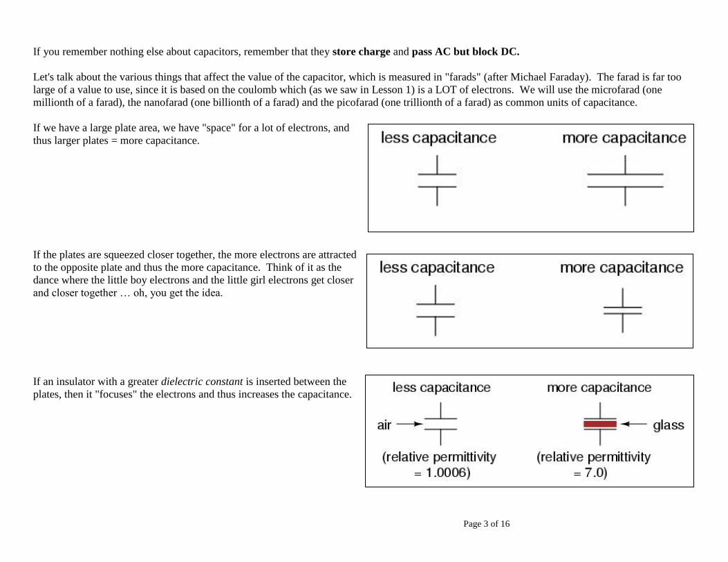
If the plates are squeezed closer together, the more electrons are attracted
to the opposite plate and thus the more capacitance. Think of it as the
dance where the little boy electrons and the little girl electrons get closer
and closer together … oh, you get the idea.
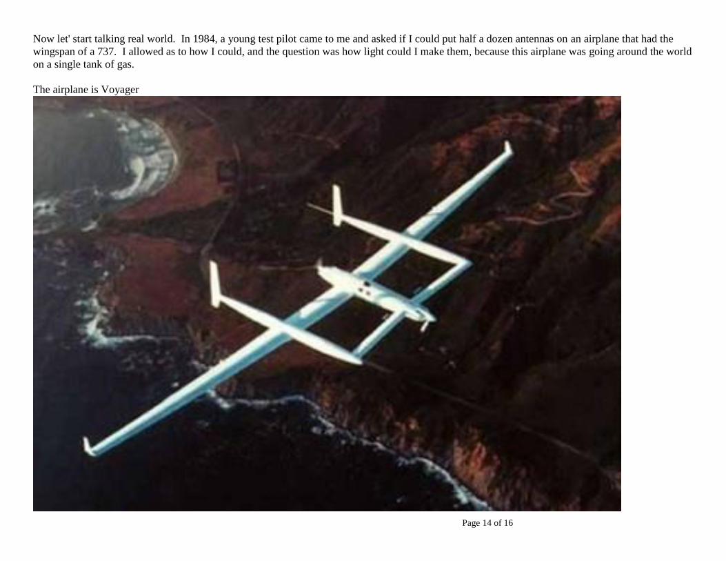
If an insulator with a greater dielectric constant is inserted between the
plates, then it "focuses" the electrons and thus increases the capacitance.

Page 4 of 16
Here is a table of some common dielectrics and their constants (all measured relative to a vacuum with constant 1.0000):
Material Relative permittivity (dielectric constant)
============================================================
Vacuum -------------------------------- 1.0000
Air -------------------------------------- 1.0006
Gasoline ------------------------------- 1.94
Mylar ----------------------------------- 2.0
PTFE, FEP ("Teflon") ---------------- 2.0
Polypropylene ------------------------ 2.20 to 2.28
ABS resin ----------------------------- 2.4 to 3.2
Polystyrene --------------------------- 2.45 to 4.0
Waxed paper ------------------------- 2.5
Transformer oil ---------------------- 2.5 to 4
Hard Rubber ------------------------- 2.5 to 4.80
Wood (Oak) -------------------------- 3.3
Silicones ------------------------------ 3.4 to 4.3
Bakelite ------------------------------- 3.5 to 6.0
Quartz, fused ------------------------- 3.8
Wood (Maple) ----------------------- 4.4
Glass ---------------------------------- 4.9 to 7.5
Castor oil ----------------------------- 5.0
Wood (Birch) ------------------------ 5.2
Mica ---------------------------------- 5.0 to 8.7
Porcelain ----------------------------- 6.5
Alumina ------------------------------ 8.0 to 10.0
Distilled water ----------------------- 80.0
Barium titanite ("ceramic") -------- 7500
One trick that is widely used is to use aluminum foil for one plate of the capacitor and a liquid conducting electrolyte to form aluminum oxide on the
plate. This hyper-thin layer of oxide acts as the dielectric in an ELECTROLYTIC capacitor. Electrolytic capacitors are generally
the most capacitance in the smallest size possible.

Page 5 of 16
Here is a picture of a few different kinds of capacitors:
Electrolytic, ceramic, and plastic (left to right)
So how do I calculate the value of a capacitor if I know all these values? Quite
simply
0.224* * 1 * /C n A d
Where C is the value of the capacitor in picofarads, ε is the dielectric constant, n is the number of plates, A is the area of one plate in square inches,
and d is the distance between the plates in inches.
For example, if I have two sheets of tinfoil a foot square separated by a mylar ("saran wrap") sheet 0.0005" thick, I will have
0.224*2*1*144 / 0.0005 128,824 . .129C pf or about nf
What are your odds of doing this
right, the first time, using a hand
calculator? Did I hear "nearly
zero"? Exactly correct. What do we use
when we have a nasty equation that may
give us fits? Did I hear
"spreadsheet"? Correct again. Go to
your engineering spreadsheet file and
find the Excel spreadsheet
makeL&C.xls, input the values for the
capacitor, and see if the sheet
doesn't come out like this (don't
worry about "frequency" or Xc yet):
Well, now I know how to make capacitors and what their values will be, but so what? What is the use of a capacitor in an electronic circuit?
Quite simply, a capacitor attempts to keep the VOLTAGE IN A CIRCUIT CONSTANT. If the supply voltage goes UP, it accepts more electrons
to try and keep that voltage down, and if the voltage goes DOWN it supplies electrons to keep the voltage up.
Thus, if a voltage is noisy, by means of a capacitor we can strip that noise from the voltage, making a nice quiet circuit.
Making Inductors and Capacitors
Jim Weir
02-Jan-01
frequency 120.0E+6 Hertz
Number of plates 2
Area of one plate 144 Square inches
Dielectric constant 2 k
Distance between plates 500.0E-6 inches
Capacitance 129.0E-9 farads
Xc 10.3E-3 ohms

Page 6 of 16
Another use of capacitors in a circuit is to set some sort of TIMING. Circuits that oscillate (generate
some sort of signal or frequency waveform) almost all use a capacitor as their timing mechanism in
some manner. How does this come about? Because of the famous "RC time constant".
Here we see a battery (Vs) connected to a switch and then to a resistor and capacitor in series. The
question becomes, what happens at the moment the switch is thrown to connect the battery to the
resistor?
The answer is that the capacitor will start to charge and will get to 63% of the battery voltage in one "time constant".
What is a time constant? It is simply the product of R and C (τ = R*C). It will get to 85% of the battery voltage in
two time constants. It will, for all practical purposes, become equal to the battery voltage in five time constants.
If you would like to see a practical example of how to use capacitors, go to www.rstengineering.com/kitplanes/ and
look at the June, July, and August 2000 issues for details on how to build a fuel gauge using capacitors.
How does that work going the other way? That is, if the capacitor is fully charged, and if I replace the
battery with a short circuit, what will the voltage across the capacitor look like after the switch is
thrown?
Pretty much the inverse of the charging equations. Now the capacitor will come to 37% of the battery
voltage within one time constant, 15% of the battery voltage in two time constants, and for all intents
and purposes be at zero volts within 5 time constants.
Now if we replace the "switch" with something that does the "switching" automatically (the classic "555" timer
is a case in point) we have a capacitor that sets the frequency of oscillation.

Page 7 of 16
Finally, we can use our capacitor to tune a radio to a particular station. If we make the plates of the
capacitor so that one stays in position while the other one is rotated in or out of the fixed plates, we can vary
the capacitance and (as we will see in a bit) vary the RESONANT frequency of the coil (L1) and capacitor
(C1). Note that C1 has an ARROW going through it. This denotes a VARIABLE capacitor.
Rather than beat this horse to death, you may wish to visit this site for some interesting insights into capacitors:
http://micro.magnet.fsu.edu/electromag/electricity/capacitance.html/
The world's first "transistor radio" was
made by Regency and called the TR-1.
It cost $50 in 1954 dollars, or about
$450 in today's money.

Page 8 of 16
While we are at it, since capacitors can store voltages and in some cases store lethal quantities of voltage and current, here are some simple rules to
remember when the voltage starts getting quite high (say, above 30 volts or so):
The Commonsense Rules (for voltages above 30 volts).
a. Work thee with a partner that he may pluck thy
mangled body from the innards of the equipment.
b. Causeth thee to tag the switch that supplieth
large doses of juice so that thy days in this vale of
tears be long.
c. Carrieth thee not ironmongery near the wires of
death, lest thy body continuously glow and thy
spouse thus have no use for thee save thy wages.
d. Stoweth one hand within thy breeches when
probing a contraption with much voltage.
e. Enjoy thy water recreation and thy voltage
sources, but lead them not into proximity.
f. Trust thy belief in the Angel of Death by
assuming that she lurketh within all equipment
until proven otherwise.
g. Disdaineth gum wrappers and pennies when
making emergency fuses.
h. The fuse doth not contain within itself the Magic Genie. It bloweth for a reason, which thou shalt ascertain before wasting copious
quantities of replacement fuses.
i. Believe that the Spirit of Whappo lives within the charged capacitor even though thee hath pulled the plug. Use thy grounding rod and thy
shorting wire judiciously.
j. Removeth thy baubles and bangles lest the spirit of Ampere be allowed to roam free within thy body.

Page 9 of 16
Inductors are nothing more than coils of wire and the INDUCTANCE of the coil is measured in HENRIES (after Joseph Henry, the electromagnet
guru). While I could go into a long song and dance about inductors, this site:
http://micro.magnet.fsu.edu/electromag/electricity/inductance.html/
says it far better than I ever could.
Note that the spreadsheet also contains a section on "inductance" whereby you can calculate the value of inductance for your little coil if you don't
want to use the formula:
2 2* * / 9 10L a n a b
Where L is the inductance (in microhenries), a is the coil radius (in inches), b is the coil length (in inches), n is the number of turns, and μ is the
permeability of the material inside the coil.
Permeability is the property of a material
(usually iron or ferrite) that concentrates
the force lines within the coil to increase
the inductance. Permeabilities can range
from 1 (air or vacuum) to upwards of
1,000,000 for some nickel-iron mixtures
such as mumetal (77% nickel, 5% copper,
2% chromium, and 16% iron.
An inductor stores energy in a MAGNETIC FIELD and has the property of trying to keep CURRENT CONSTANT in a circuit. It does this by
varying the voltage across the inductor in an attempt to keep the current constant. There are several uses for this sort of behavior; one of the most
common is shown here:
This is a common SPARK COIL on an internal combustion automobile engine. When it comes time for a spark plug to ignite the gasoline vapor
inside the cylinder, a current is supplied to the coil and then the circuit is abruptly broken with a switch controlled by the engine. The coil attempts to
keep the current constant by the use of the magnetic field to generate a huge voltage at the end of the coil, which is then allowed to jump across a
small gap in the plug, igniting the gasoline vapor.
Diameter of coil 250.0E-3 inches
Length of coil 350.0E-3 inches
Number of turns 9 n
Permeability 1 u
Inductance 273.6E-9 henries
Xl 206.3E+0

Page 10 of 16
The inductor has a TIME CONSTANT similar to a capacitor. While the magnetic field takes a fairly short time to build up, it is not instantaneous,
but builds up (and is discharged) as a function of the circuit resistance and the inductance of the coil.

Page 11 of 16
ANTENNAS is a subject that books … nay entire SERIES of books have been written about. We will investigate some rather simple antennas in our
lab today. The one thing that you want to remember about antennas is that almost all of them are built on the QUARTER-WAVELENGTH
principle.
Son of student in 2008 built an aviation band antenna over the Winter break. Flying copilot for the airlines today.

Page 12 of 16
What's a quarter-wavelength? For that matter, what's a WAVE???
As we saw from our study of capacitors, a WAVE is a
repetitive signal that goes through a zero, a maximum, a zero,
a minimum, and back to a zero on a regular basis. Here is a
wave and a quarter-wave:
If we go back and think about it, we can see that if the wave travels at the speed of light (186,000 miles per hour or 3 x 10⁸ meters per second, both of
them are equivalent) then if a wave has a frequency of so many cycles per second, then it will travel some distance in that time. In particular, it will
travel a distance equal to speed of light in distance per second
/frequency of the wave in cycles per second .
If light travels 186,000 miles per second, then it travels (186,000 * 5280 feet per second * 12 inches per foot) or 11.8 x 109 inches per second. If you
want to do metric, then if it does 3 * 108 meters per second then it does 3 E8 * 39.37 or 11.8 x 10
9 inches per second. Same number, any way you
want to look at it.
So, since we are committed in this class to inches, then we can say that we will work with 11.8 x 109 inches per second as the speed of light.

Page 13 of 16
Now just for a practical example, we want to cut a QUARTER WAVE for the middle of the FM radio broadcast band at 98 MHz. That's 98 x 106
cycles per second (98 Megahertz). Dividing the speed of light by the frequency, we come up with a WAVELENGTH of 120 inches.
But antennas are made on QUARTER wave lengths, so our antenna is going to be 30 inches long.
But wait a minute. That's a quarter of a wave for each ELEMENT, and in general, there are TWO elements to a di (greek word for two) pole, or
dipole antenna. So now we know our FM antenna is going to be 60 inches (5 feet) long. Which is just about correct.
A simple dipole antenna is TWO quarter waves (or a half-wave) elements end to end and fed in the middle with coaxial cable. Thus, a true
dipole antenna measures half a wavelength from tip to tip. When you adjusted the length of the "rabbit ears" on your TV set (back in the
days when we had analog TV) what you were really doing is trying to make the antenna into a half-wave dipole with each of the ears being a
quarter wave long and fed in the middle with TV antenna wire.
Page 14 of 16
Now let' start talking real world. In 1984, a young test pilot came to me and asked if I could put half a dozen antennas on an airplane that had the
wingspan of a 737. I allowed as to how I could, and the question was how light could I make them, because this airplane was going around the world
on a single tank of gas.
The airplane is Voyager
Page 15 of 16
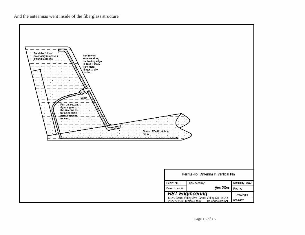
And the anteannas went inside of the fiberglass structure

Page 16 of 16