Embed Size (px)
Citation preview

A.B.N 76078600450A.C.N 078 600 450
P.O.Box 1168Kangaroo Flat, Vic
3555Free call: 1800 630116
Email: [email protected]: www.sierraproducts.com.au
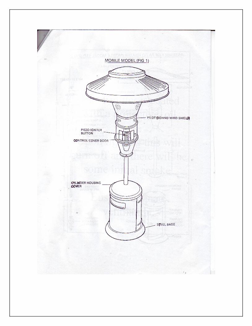
Sierra 11P Mobile Patio Heater Mobile Model (G.C. Appliance No. 36 237 07)
AGA Approval No. 4800
Assembly, Servicing & Users Instructions.(Hand these instructions to the user.)
(Keep for future reference.)
IMPORTANT: this appliance shall be installed in accordance with:Manufacturers’ installation instructions, Local Gas Fitting regulations, Municipal Building Codes, AGA Installation code for gas burning equipment (AG 601),Electrical Supply Authority and any other relevant statutory regulation.
This appliance must be installed, serviced and removed by an authorized person.
The 11P is approved by the Australian Gas Association for Propane Gas only.
Contents:

1.0 Introduction2.0 Technical Specifications2.1 General3.0 Packing and Assembly3.1 Packing3.2 Assembly of Patio Heater Mobile Model (REF. FIG 2)3.3 To Fit 9Kg Propane Gas Cylinder (Not Supplied)4.0 To Light the Heater5.0 To Turn the Heater off6.0 Cleaning 7.0 Winter Storage8.0 Servicing8.1 Fault Finding8.2 Flame Supervision Device, Pilot Burner and Main Burner8.3 Piezo Ignition9.0 Short Parts List10.0 General Servicing Procedure11.0 Replacement/ Exchange of Components
Sierra Patio Heater
1.0 Introduction.
The Sierra Patio Cone Heaters combine the benefits of radiant heating to produce overall comfort conditions to patios, swimming pools and similar outdoor leisure areas. The heaters are fitted with a flame supervision safety device.
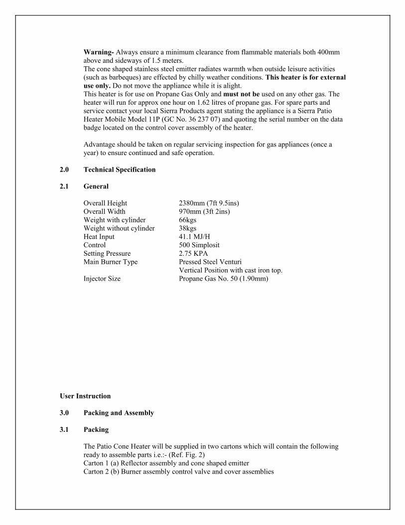
Warning- Always ensure a minimum clearance from flammable materials both 400mm above and sideways of 1.5 meters. The cone shaped stainless steel emitter radiates warmth when outside leisure activities (such as barbeques) are effected by chilly weather conditions. This heater is for external use only. Do not move the appliance while it is alight. This heater is for use on Propane Gas Only and must not be used on any other gas. The heater will run for approx one hour on 1.62 litres of propane gas. For spare parts and service contact your local Sierra Products agent stating the appliance is a Sierra Patio Heater Mobile Model 11P (GC No. 36 237 07) and quoting the serial number on the data badge located on the control cover assembly of the heater.
Advantage should be taken on regular servicing inspection for gas appliances (once a year) to ensure continued and safe operation.
2.0 Technical Specification
2.1 General
Overall Height 2380mm (7ft 9.5ins)Overall Width 970mm (3ft 2ins)Weight with cylinder 66kgsWeight without cylinder 38kgsHeat Input 41.1 MJ/HControl 500 Simplosit Setting Pressure 2.75 KPA Main Burner Type Pressed Steel Venturi
Vertical Position with cast iron top.Injector Size Propane Gas No. 50 (1.90mm)
User Instruction
3.0 Packing and Assembly
3.1 Packing
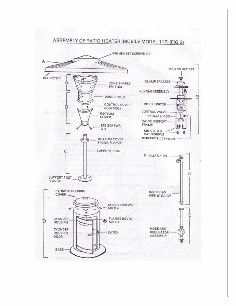
The Patio Cone Heater will be supplied in two cartons which will contain the following ready to assemble parts i.e.:- (Ref. Fig. 2)Carton 1 (a) Reflector assembly and cone shaped emitter Carton 2 (b) Burner assembly control valve and cover assemblies

(c) Support post (d) Cylinder housing base cover (e) Inner gas Pipe
(f) Hose assembly and regulator and ‘O’ Clip
3.2 Assembly of Patio Heater Mobile Model (Ref. Fig. 2)
1. Unpack and stand cylinder housing (D) on flat even surface2. Open cylinder housing door by releasing catch remove packing bolt securing support post flange. Remove four wing nuts from four bolts in top of housing. Raise support post (C) and assembly (B) by lifting from centre of cylinder housing cover until flange engages with the four bolts in top of housing.3. Secure into position with the four wing nuts and tighten firmly.4. Unpack and dismantle the reflector and cone shaped emitter assembly (A) by removing the 3 x M8 hex set screws.5. Remove the clamp plate and M8 x 20 hex set screws that secures the packing piece to the burner top. 6. Place the cone shaped emitter on top of the burner and refit clamp plate and M8 x 20 hex set screw and tighten firmly.7. Fit reflector assembly (A) by lifting into position over the cone shaped emitter and securing with the 3 x M8 hex set screws.
3.3 To Fit 9Kg Propane Gas Cylinder (not supplied)
Warning- fitting gas cylinder to appliance must be in accordance with the code of practice. Ensure all naked flames are extinguished.
1. Open cylinder housing door to gain access to the hose and regulator assembly- Ref. Fig. 2 (D) and (F).2. Check that P.O.L metal connection of regulator is clean. (Dirty connections can cause leaks.) 3. Check that cylinder valve is in the closed position before removing plug from outlet connection.4. Screw regulator connection into cylinder valve and tighten with spanner firmly to give a gas tight fit. 5. Fit cylinder into base recess of housing by sliding backwards in a vertical position, taking care not to kink hose assembly. 6. Close cylinder housing door and secure with catch.
User Instruction Continued.
4.0 To Light the Heater
1. Turn on gas at cylinder valve by turning anti- clockwise (by hand). Access by cut out in top of the door, or open door.2. Slide open control cover door.
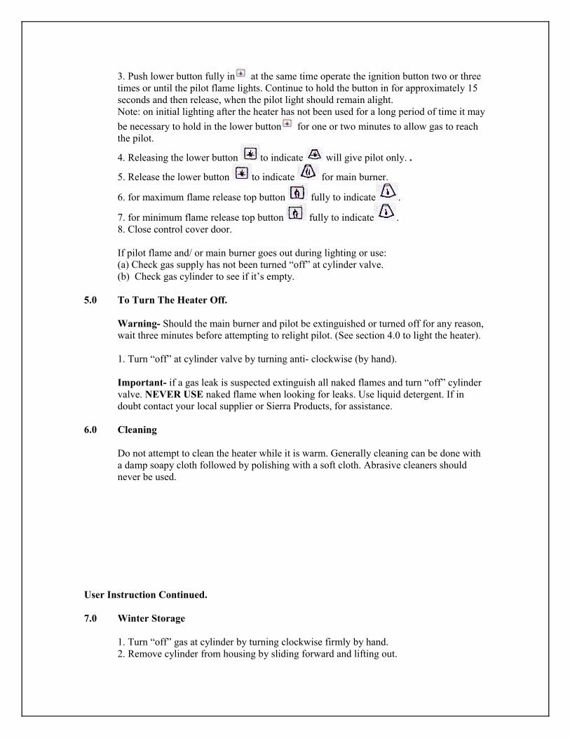
3. Push lower button fully in at the same time operate the ignition button two or three times or until the pilot flame lights. Continue to hold the button in for approximately 15 seconds and then release, when the pilot light should remain alight. Note: on initial lighting after the heater has not been used for a long period of time it may be necessary to hold in the lower button for one or two minutes to allow gas to reach the pilot.
4. Releasing the lower button to indicate will give pilot only. .
5. Release the lower button to indicate for main burner.
6. for maximum flame release top button fully to indicate .
7. for minimum flame release top button fully to indicate .8. Close control cover door.
If pilot flame and/ or main burner goes out during lighting or use: (a) Check gas supply has not been turned “off” at cylinder valve. (b) Check gas cylinder to see if it’s empty.
5.0 To Turn The Heater Off.
Warning- Should the main burner and pilot be extinguished or turned off for any reason, wait three minutes before attempting to relight pilot. (See section 4.0 to light the heater).
1. Turn “off” at cylinder valve by turning anti- clockwise (by hand).
Important- if a gas leak is suspected extinguish all naked flames and turn “off” cylinder valve. NEVER USE naked flame when looking for leaks. Use liquid detergent. If in doubt contact your local supplier or Sierra Products, for assistance.
6.0 Cleaning
Do not attempt to clean the heater while it is warm. Generally cleaning can be done with a damp soapy cloth followed by polishing with a soft cloth. Abrasive cleaners should never be used.
User Instruction Continued.
7.0 Winter Storage
1. Turn “off” gas at cylinder by turning clockwise firmly by hand.2. Remove cylinder from housing by sliding forward and lifting out.

3. Unscrew regulator connection (clockwise) from cylinder valve (always replace plug safety cap when putting into storage to prevent dirt entering the cylinder valve.) 4. To dismantle heater for storage reverse the assembly procedure. (See 3.2)
Servicing Instructions.
8.0 Servicing.
Important Note: in the interest of safety it is recommended that all services are carried out by an authorized person in accordance with Gas Installation Code AG601.
8.1 Fault Finding,
8.2 Flame Supervision Device, Pilot Burner and Main Burner.
Pilot flame and/ or main burner goes out:
1. Check gas supply has not been turned “off” at cylinder valve. 2. Check gas cylinder to see if it is empty.3. Check thermocouple connection and flame supervision device (F.S.D) 4. Check if unit is on level ground.
Remedy: Replace Part NumberThermocouple 2894
8.3 Piezo Ignition
No Spark:
1. Check that connections are sound on lead ends.2. Check that piezo ignition is creating sufficient spark when button is pushed and the spark gap is 5mm +/- 0.5mm (3/16in). (See Fig. 5).
Remedy: Replace Part NumberIgnition Lead 4540Piezo Ignition 4542Ignition Electrode 4543
9.0 Short Parts List Appliance name and model Sierra Products Mobile Model 11P.
Manufacturer: Sierra Space Heating Ltd1 Anson Road Martlesham Heath Industrial Estate Ipswitch, Suffolk. IP57RG
Australian Distributor: Sierra Products P/L P.O.Box 1168Kangaroo Flat Vic 3555Freecall: 1800630116
9.0 Short Parts List Continued.
Key Number Description Qty Code1 Main Injector Propane Gas No. 50 1 18952 Pilot Injector Propane Gas 4209 1 29923 Ignition Electrode 1 4543
4 Ignition Lead 1 45405 Piezo Igniter 66212/002 1 45426 Sit 500 Simplisit Valve 1 27427 Burner Complete 1 18908 Pilot Burner 27A4G 1 28319 Thermocouple 1 289410 Low Pressure Regulator 1 302711 Mercury Tilt Switch 1 T03/1052
10.0 General Servicing Procedure.
1. Turn off gas at cylinder valve.2. Remove reflector assembly (Fig. 2) assembly (A) by unscrewing 3 x M8 hex set screws.3. Unscrew the M8 hex set screw (located in the center cone shaped emitter) and remove emitter for examination and cleaning. Wire brush inside and outside of perforated emitter cone to remove any deposits. 4. Remove wind shield guard to expose the main burner assembly and pilot burner assembly, examine, clean, or replace (See burner).
Main InjectorPilot InjectorIgnition ElectrodeThermocouple/ Mercury Tilt Switch
5. Refer to 9.0 spares list part codes. Reassembly is a reverse of the above procedure.
11.0 Replacement/ exchange of components.
1. Main Injector
Carry out general servicing 1-4.Unscrew Injector from injector holder.

2. Pilot Injector
Carry out general servicing 1-4Unscrew nut securing thermocouple to pilot bracket/ assembly.Pull off ignition lead to electrodeDisconnect pilot supply pipe from pilot injector.Remove two screws securing pilot assembly to support bracket. Unscrew pilot injector from pilot burner. Re-assemble in reverse order
3. Piezo Igniter Lead.
Carry out general servicing 1-4.Pull off ignition lead to Piezo igniter and electrode, cut off tie securing lead to pilot supply and thermocouple.Fit new ignition lead and secure with new cable tie.
4. Ignition Electrode
Carry out general servicing 1-4.Unscrew nut securing thermocouple to pilot bracket/ assemblyPull off ignition lead to electrode.Remove screw securing electrode to pilot assembly and lift out electrode. Fit new electrode, check spark gas is 5mm +/- 0.5mm (3/16in). (See Fig. 5)
5. Thermocouple
Carry out general service 1-4Unscrew nuts securing thermocouple to pilot bracket/ assembly at one end and the F.S.D at the other end. Disconnect tilt switch leads. Cut off cable tie securing ignition lead to thermocouple. On reassemble fit new cable tie.
6. Piezo Igniter.
Pull of ignition lead from rear of igniter.Unscrew nut securing piezo igniter to support bracket.
7. Main Burner.
Carry out general servicing 1-4. Remove two screws securing burner to injector assembly and burner pan.

Warranty
Guarantees all products supplied against any manufacturing defect for a twelve month period from date of sale. The Warranty does not cover the following:
1. Faults/ Failure caused by misuse, neglect or faulty adjustments by the user.2. Failures resulting from not using the product in accordance with the operating instruction manual.3. Failure as a result of sudden impact.4. Failure which had occurred from normal fair, wear and tear.5. Any unit which has been serviced or repaired, taken apart of tampered with by any person not being a qualified installer.6. The benefits conferred by this warranty and guarantee are in addition to all other rights and remedies in respect of such appliance has under the Trade Practices Act (Commonwealth) and other state and territory laws.

Warning
This Emitter is coated with a protective oil.
Upon lighting this will burn off and there will be some initial smoke.
Ensure adequate ventilation.