Embed Size (px)
Citation preview

Siemens S5 (AS511)Driver Help
© 2012 Kepware Technologies

Siemens S5 (AS511) Driver Help
Table of ContentsTable of Contents 2Siemens S5 (AS511) Driver Help 4Overview 4
Device Setup 5Modem Setup 6
Data Types Description 7Address Descriptions 8Siemens S5 (AS511) 90U Address Descriptions 8Siemens S5 (AS511) 95U Address Descriptions 10Siemens S5 (AS511) 100U-100 Address Descriptions 12Siemens S5 (AS511) 100U-101 Address Descriptions 14Siemens S5 (AS511) 100U-103 Address Descriptions 16Siemens S5 (AS511) 101U Address Descriptions 19Siemens S5 (AS511) 115U-941 Address Descriptions 21Siemens S5 (AS511) 115U-942 Address Descriptions 23Siemens S5 (AS511) 115U-943 Address Descriptions 25Siemens S5 (AS511) 115U-944 Address Descriptions 27Siemens S5 (AS511) 115U-945 Address Descriptions 29Siemens S5 (AS511) 135U-921 Address Descriptions 32Siemens S5 (AS511) 135U-922 Address Descriptions 34Siemens S5 (AS511) 135U-928 Address Descriptions 36Siemens S5 (AS511) 155U-946 Address Descriptions 38Siemens S5 (AS511) 155U-947 Address Descriptions 40
Error Descriptions 43Address Validation 43Array support is not available for the specified address: '<address>' 43Address '<address>' is out of range for the specified device or register 43Data Type '<type>' is not valid for device address '<address>' 44Device address '<address>' is not supported by model '<model name>' 44Device address '<address>' contains a syntax error 44Missing address 44Serial Communications 44Communications error on '<channel name>' [<error mask>] 44COMn does not exist 45COMn is in use by another application 45Error opening COMn 45Unable to set comm parameters on COMn 45Device Status Messages 45Device '<device name>' is not responding 46
www. kepware.com
2
Siemens S5 (AS511) Driver Help
Unable to write to '<address>' on device '<device name>' 46Driver Warning Messages 46Data Block DB '<block number>' not defined in '<device name>' write operation has failed 46Failure reading device '<device name>' configuration 46Protocol Error-Number of bytes received = '<num bytes>' Expected = '<num bytes>' 47Requested Data Block DB'<block number>' not defined in '<device name>' block has been disabled 47
Index 48
www. kepware.com
3

Siemens S5 (AS511) Driver Help
Siemens S5 (AS511) Driver HelpHelp version 1.015
OverviewWhat is the Siemens S5 (AS511) Driver?
Device SetupHow do I configure a device for use with this driver?
Data Types DescriptionWhat data types does this driver support?
Address DescriptionsHow do I address a data location on a Siemens S5 (AS511) Driver?
Error DescriptionsWhat error messages does the Siemens S5 (AS511) Driver produce?
OverviewThe Siemens S5 (AS511) Driver provides an easy and reliable way to connect Siemens S5 (AS511) devices to OPCClient applications, including HMI, SCADA, Historian, MES, ERP and countless custom applications. It is intendedfor use with Siemens S5 PLCs communicating via the front programming port using AS511 protocol (which is spe-cific for each Siemens device). This driver has been designed to operate with a set range of Siemens equipment:it is not recommended for use on devices that are not supported.
The Siemens S5 PLC family has a unique memory structure. Data within the PLC is not at fixed locations within thePLC's memory space. As the PLC logic is created and modified, this memory space is continuously updated andrevised. When these revisions occur, the location of the key data elements (such as flags, timers, counters, I/O,and data blocks) can move around in the PLC's memory. The Siemens S5 (AS511) Driver has been designed toread the location of these memory elements when the driver begins operation or detects a communications error.If the PLC configuration changes, users must restart the Siemens S5 (AS511) Driver or pull and replace the cableconnection. Both of these actions will cause the Siemens S5 (AS511) Driver to reacquire the location of all PLCmemory elements.
www. kepware.com
4

Siemens S5 (AS511) Driver Help
Device SetupSupported DevicesSiemens S5-90USiemens S5-95USiemens S5-100U-100Siemens S5-100U-101Siemens S5-100U-103Siemens S5-101USiemens S5-115U-941Siemens S5-115U-942Siemens S5-115U-943Siemens S5-115U-944Siemens S5-115U-945Siemens S5-135U-921Siemens S5-135U-922Siemens S5-135U-928Siemens S5-155U-946Siemens S5-155U-947
Communication ProtocolAS511 Current Loop
Supported Communication ParametersBaud: 9600 (Fixed)Parity: Even (Fixed)Data Bits: 8 (Fixed)Stop Bit: 1 (Fixed)
Ethernet EncapsulationThis driver supports Ethernet Encapsulation, which allows communications with serial devices attached to an Eth-ernet network using a terminal server or device server. It may be invoked through the COM ID dialog in ChannelProperties. When used directly with a serial port, this driver only supports a single connection to a single con-troller per serial port. When operating in Ethernet Encapsulation Mode, the driver will support up to 30 con-trollers per channel. In this mode, a single controller can be paired with a terminal server/device server to form asingle node. For more information, refer to the server's help documentation.
Note: The Siemens S5 AS511 protocol is sensitive to timing and gaps in the communications stream. If the net-work experiences heavy packet loss or delay while using Ethernet Encapsulation, the Siemens S5 (AS511) Drivermay report a large number of timeout errors or be unable to communicate. In some cases, using a switched net-work can help reduce these delays; however, it is not a guaranteed solution.
Cable Connections
www. kepware.com
5

Siemens S5 (AS511) Driver Help
Modem SetupThis driver supports modem functionality. For more information, please refer to the topic "Modem Support" in theOPC Server Help documentation.
www. kepware.com
6
Siemens S5 (AS511) Driver Help
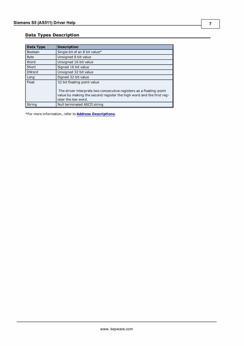
Data Types Description
Data Type DescriptionBoolean Single bit of an 8 bit value*Byte Unsigned 8 bit valueWord Unsigned 16 bit valueShort Signed 16 bit valueDWord Unsigned 32 bit valueLong Signed 32 bit valueFloat 32 bit floating point value
The driver interprets two consecutive registers as a floating-pointvalue by making the second register the high word and the first reg-ister the low word.
String Null terminated ASCII string
*For more information, refer to Address Descriptions.
www. kepware.com
7

Siemens S5 (AS511) Driver Help
Address DescriptionsAddress specifications vary depending on the model in use. Select a link from the following list to obtain specificaddress information for the model of interest.
Siemens S5 (AS511) 90USiemens S5 (AS511) 95USiemens S5 (AS511) 100U-100Siemens S5 (AS511) 100U-101Siemens S5 (AS511) 100U-103Siemens S5 (AS511) 101USiemens S5 (AS511) 115U-941Siemens S5 (AS511) 115U-942Siemens S5 (AS511) 115U-943Siemens S5 (AS511) 115U-944Siemens S5 (AS511) 115U-945Siemens S5 (AS511) 135U-921Siemens S5 (AS511) 135U-922Siemens S5 (AS511) 135U-928Siemens S5 (AS511) 155U-946Siemens S5 (AS511) 155U-947
Siemens S5 (AS511) 90U Address DescriptionsThe default data types for dynamically defined tags are shown in bold.
Address Type Range Type AccessDiscrete Inputs I0.b-I127.b
.b is Bit Number 0-7
IB0-IB127
IW0-IW126
ID0-ID124
Boolean
Byte
Word, Short
DWord, Long
Read/Write
Read/Write
Read/Write
Read/WriteDiscrete Inputs
Note: I and E access the samememory area.
E0.b-E127.b.b is Bit Number 0-7
EB0-EB127
EW0-EW126
ED0-ED124
Boolean
Byte
Word, Short
DWord, Long
Read/Write
Read/Write
Read/Write
Read/WriteDiscrete Outputs Q0.b-Q127.b
.b is Bit Number 0-7
QB0-QB127
QW0-QW126
QD0-QD124
Boolean
Byte
Word, Short
DWord, Long
Read/Write
Read/Write
Read/Write
Read/WriteDiscrete Outputs
Note: Q and A access the samememory area
A0.b-A127.b.b is Bit Number 0-7
AB0-AB127
AW0-AW126
AD0-AD124
Boolean
Byte
Word, Short
DWord, Long
Read/Write
Read/Write
Read/Write
Read/WriteInternal Memory F0.b-F255.b
.b is Bit Number 0-7
FB0-FB255
Boolean
Byte
Read/Write
Read/Write
www. kepware.com
8

Siemens S5 (AS511) Driver Help
FW0-FW254
FD0-FD252
Word, Short
DWord, Long
Read/Write
Read/WriteInternal Memory
Note: F and M access the samememory area.
M0.b-M255.b.b is Bit Number 0-7
MB0-MB255
MW0-MW254
MD0-MD252
Boolean
Byte
Word, Short
DWord, Long
Read/Write
Read/Write
Read/Write
Read/WriteData Block
Boolean
DB1-N:KM0.b-KM255.b
1-N is Block Number
.b is Bit Number 0-15
Boolean Read/Write
Data Block
Left Byte
DB1-N:KL0-KL255
1-N is Block Number
Byte Read/Write
Data Block
Right Byte
DB1-N:KR0-KR255
1-N is Block Number
Byte Read/Write
Data Block
Unsigned Word
DB1-N:KH0-KH255
1-N is Block Number
Word, Short Read/Write
Data Block
Signed Word
DB1-N:KF0-KF255
1-N is Block Number
Short, Word Read/Write
Data Block
Signed Long
DB1-N:KD0-KD254
1-N is Block Number
Long, DWord Read/Write
Data Block
Float
DB1-N:KG0-KG254
1-N is Block Number
Float Read/Write
Data Block
String
DB1-N:KS0.l-KS255.l
1-N is Block Number
l is String Length (2-254)
String Read/Write
Data Block
Timer
DB1-N:KT0-KT255
1-N is Block Number
Long Read/Write
Data Block
Counter
DB1-N:KC0-KC255
1-N is Block Number
Word, Short Read/Write
Timer Current Values T0-T127 Long Read/WriteCounter Current Values C0-C127 Word, Short Read/WriteCounter Current Values Z0-Z127 Word, Short Read/Write
All offsets for memory types I, Q, and F represent a byte starting location within the specified memory type.
Examples1. To access bit 3 of Internal Memory F20, declare an address as follows:F20.3
2. To access Data Block 5 as word memory at element 30, declare an address as follows:DB5:KH30
3. To access Data Block 2 element 20 and bit 7, declare an address as follows:DB2:KM20.7
4. To access Data Block 1 as left byte memory at element 10, declare an address as follows:DB1:KL10
www. kepware.com
9

Siemens S5 (AS511) Driver Help
5. To access Internal Memory F20 as a DWORD, declare an address as follows:FD20
6. To access Input Memory I10 as a Word, declare an address as follows:IW10
Note: Use caution when modifying Word, Short, DWord, and Long types. For I, Q, and F each address starts at abyte offset within the device. Therefore, Words FW0 and FW1 overlap at byte 1. Writing to FW0 will also modifythe value held in FW1. Similarly, DWord, and Long types can also overlap. It is recommended that these memorytypes be used so that overlapping does not occur. For example, when using DWords, use FD0, FD4, FD8 ... andso on to prevent overlapping bytes.
TimersThe Siemens S5 (AS511) Driver automatically scales T and KT values based on the Siemens S5 time format. Thevalue returned for either a T or KT memory type will already be scaled using the appropriate Siemens time base.As a result, the values are always returned as a count of milliseconds. When writing to T or KT memory types, theSiemens time base will also be applied. To write a value to a timer in the controller, simply write the desired valueas a count of milliseconds to the appropriate timer.
CountersCounters are stored as three BCD digits on the device. The largest value that can be read or written to a counter is999.
StringsString data is stored in data block registers, thus the actual number of bytes used to store the data is an evennumber. For example, if a string of length 5 is specified, say by DB11:KS1.5, then 3 registers (6 bytes) will beused to store the string data. When writing strings shorter than the maximum specified length (5 in this exam-ple), a null terminator (0x00) will be added to the end of the string. When strings are read, the full range of reg-isters are read (3 in this example). Use of string tags with overlapping address ranges should be avoided due tothe effects of the null terminators.
Siemens S5 (AS511) 95U Address DescriptionsThe default data types for dynamically defined tags are shown in bold.
Address Type Range Type AccessDiscrete Inputs I0.b-I127.b
.b is Bit Number 0-7
IB0-IB127
IW0-IW126
ID0-ID124
Boolean
Byte
Word, Short
DWord, Long
Read/Write
Read/Write
Read/Write
Read/WriteDiscrete Inputs
Note: I and E access the samememory area.
E0.b-E127.b.b is Bit Number 0-7
EB0-EB127
EW0-EW126
ED0-ED124
Boolean
Byte
Word, Short
DWord, Long
Read/Write
Read/Write
Read/Write
Read/WriteDiscrete Outputs Q0.b-Q127.b
.b is Bit Number 0-7
QB0-QB127
QW0-QW126
QD0-QD124
Boolean
Byte
Word, Short
DWord, Long
Read/Write
Read/Write
Read/Write
Read/WriteDiscrete Outputs A0.b-A127.b
.b is Bit Number 0-7
AB0-AB127
Boolean
Byte
Read/Write
Read/Write
www. kepware.com
10

Siemens S5 (AS511) Driver Help
Note: Q and A access the samememory area.AW0-AW126
AD0-AD124
Word, Short
DWord, Long
Read/Write
Read/WriteInternal Memory F0.b-F255.b
.b is Bit Number 0-7
FB0-FB255
FW0-FW254
FD0-FD252
Boolean
Byte
Word, Short
DWord, Long
Read/Write
Read/Write
Read/Write
Read/WriteInternal Memory
Note: F and M access the samememory area.
M0.b-M255.b.b is Bit Number 0-7
MB0-MB255
MW0-MW254
MD0-MD252
Boolean
Byte
Word, Short
DWord, Long
Read/Write
Read/Write
Read/Write
Read/WriteData Block
Boolean
DB1-N:KM0.b-KM255.b
1-N is Block Number
.b is Bit Number 0-15
Boolean Read/Write
Data Block
Left Byte
DB1-N:KL0-KL255
1-N is Block Number
Byte Read/Write
Data Block
Right Byte
DB1-N:KR0-KR255
1-N is Block Number
Byte Read/Write
Data Block
Unsigned Word
DB1-N:KH0-KH255
1-N is Block Number
Word, Short Read/Write
Data Block
Signed Word
DB1-N:KF0-KF255
1-N is Block Number
Short, Word Read/Write
Data Block
Signed Long
DB1-N:KD0-KD254
1-N is Block Number
Long, DWord Read/Write
Data Block
Float
DB1-N:KG0-KG254
1-N is Block Number
Float Read/Write
Data Block
String
DB1-N:KS0.l-KS255.l
1-N is Block Number
l is String Length (2-254)
String Read/Write
Data Block
Timer
DB1-N:KT0-KT255
1-N is Block Number
Long Read/Write
Data Block
Counter
DB1-N:KC0-KC255
1-N is Block Number
Word, Short Read/Write
Timer Current Values T0-T127 Long Read/WriteCounter Current Values C0-C127 Word, Short Read/WriteCounter Current Values Z0-Z127 Word, Short Read/Write
All offsets for memory types I, Q, and F represent a byte starting location within the specified memory type.
Examples1. To access bit 3 of Internal Memory F20, declare an address as follows:F20.3
www. kepware.com
11

Siemens S5 (AS511) Driver Help
2. To access Data Block 5 as word memory at element 30, declare an address as follows:DB5:KH30
3. To access Data Block 2 element 20 and bit 7, declare an address as follows:DB2:KM20.7
4. To access Data Block 1 as left byte memory at element 10, declare an address as follows:DB1:KL10
5. To access Internal Memory F20 as a DWORD, declare an address as follows:FD20
6. To access Input Memory I10 as a Word, declare an address as follows:IW10
Note: Use caution when modifying Word, Short, DWord, and Long types. For I, Q, and F each address starts at abyte offset within the device. Therefore, Words FW0 and FW1 overlap at byte 1. Writing to FW0 will also modifythe value held in FW1. Similarly, DWord, and Long types can also overlap. It is recommended that these memorytypes be used so that overlapping does not occur. For example, when using DWords, use FD0, FD4, FD8 ... andso on to prevent overlapping bytes.
TimersThe Siemens S5 (AS511) Driver automatically scales T and KT values based on the Siemens S5 time format. Thevalue returned for either a T or KT memory type will already be scaled using the appropriate Siemens time base.As a result, the values are always returned as a count of milliseconds. When writing to T or KT memory types, theSiemens time base will also be applied. To write a value to a timer in the controller, simply write the desired valueas a count of milliseconds to the appropriate timer.
CountersCounters are stored as three BCD digits on the device. The largest value that can be read or written to a counter is999.
StringsString data is stored in data block registers, thus the actual number of bytes used to store the data is an evennumber. For example, if a string of length 5 is specified, say by DB11:KS1.5, then 3 registers (6 bytes) will beused to store the string data. When writing strings shorter than the maximum specified length (5 in this exam-ple), a null terminator (0x00) will be added to the end of the string. When strings are read, the full range of reg-isters are read (3 in this example). Use of string tags with overlapping address ranges should be avoided due tothe effects of the null terminators.
Siemens S5 (AS511) 100U-100 Address DescriptionsThe default data types for dynamically defined tags are shown in bold.
Address Type Range Type AccessDiscrete Inputs I0.b-I127.b
.b is Bit Number 0-7
IB0-IB127
IW0-IW126
ID0-ID124
Boolean
Byte
Word, Short
DWord, Long
Read/Write
Read/Write
Read/Write
Read/WriteDiscrete Inputs
Note: I and E access the samememory area.
E0.b-E127.b.b is Bit Number 0-7
EB0-EB127
EW0-EW126
ED0-ED124
Boolean
Byte
Word, Short
DWord, Long
Read/Write
Read/Write
Read/Write
Read/WriteDiscrete Outputs Q0.b-Q127.b
.b is Bit Number 0-7
QB0-QB127
Boolean
Byte
Read/Write
Read/Write
www. kepware.com
12

Siemens S5 (AS511) Driver Help
QW0-QW126
QD0-QD124
Word, Short
DWord, Long
Read/Write
Read/WriteDiscrete Outputs
Note: Q and A access the samememory area.
A0.b-A127.b.b is Bit Number 0-7
AB0-AB127
AW0-AW126
AD0-AD124
Boolean
Byte
Word, Short
DWord, Long
Read/Write
Read/Write
Read/Write
Read/WriteInternal Memory F0.b-F255.b
.b is Bit Number 0-7
FB0-FB255
FW0-FW254
FD0-FD252
Boolean
Byte
Word, Short
DWord, Long
Read/Write
Read/Write
Read/Write
Read/WriteInternal Memory
Note: F and M access the samememory area.
M0.b-M255.b.b is Bit Number 0-7
MB0-MB255
MW0-MW254
MD0-MD252
Boolean
Byte
Word, Short
DWord, Long
Read/Write
Read/Write
Read/Write
Read/WriteData Block
Boolean
DB1-N:KM0.b-KM255.b1-N is Block Number
.b is Bit Number 0-15
Boolean Read/Write
Data Block
Left Byte
DB1-N:KL0-KL255
1-N is Block Number
Byte Read/Write
Data Block
Right Byte
DB1-N:KR0-KR255
1-N is Block Number
Byte Read/Write
Data Block
Unsigned Word
DB1-N:KH0-KH255
1-N is Block Number
Word, Short Read/Write
Data Block
Signed Word
DB1-N:KF0-KF255
1-N is Block Number
Short, Word Read/Write
Data Block
Signed Long
DB1-N:KD0-KD254
1-N is Block Number
Long, DWord Read/Write
Data Block
Float
DB1-N:KG0-KG254
1-N is Block Number
Float Read/Write
Data Block
String
DB1–N:KS0.l–KS255.l
1–N is Block Number
l is String Length (2–254)
String Read/Write
Data Block
Timer
DB1-N:KT0-KT255
1-N is Block Number
Long Read/Write
Data Block
Counter
DB1-N:KC0-KC255
1-N is Block Number
Word, Short Read/Write
Timer Current Values T0-T127 Long Read/Write
www. kepware.com
13

Siemens S5 (AS511) Driver Help
Counter Current Values C0-C127 Word, Short Read/WriteCounter Current Values Z0-Z127 Word, Short Read/Write
All offsets for memory types I, Q, and F represent a byte starting location within the specified memory type.
Examples1. To access bit 3 of Internal Memory F20, declare an address as follows:F20.3
2. To access Data Block 5 as word memory at element 30, declare an address as follows:DB5:KH30
3. To access Data Block 2 element 20 and bit 7, declare an address as follows:DB2:KM20.7
4. To access Data Block 1 as left byte memory at element 10, declare an address as follows:DB1:KL10
5. To access Internal Memory F20 as a DWORD, declare an address as follows:FD20
6. To access Input Memory I10 as a Word, declare an address as follows:IW10
Note: Use caution when modifying Word, Short, DWord, and Long types. For I, Q, and F each address starts at abyte offset within the device. Therefore, Words FW0 and FW1 overlap at byte 1. Writing to FW0 will also modifythe value held in FW1. Similarly, DWord, and Long types can also overlap. It is recommended that these memorytypes be used so that overlapping does not occur. For example, when using DWords, use FD0, FD4, FD8 ... andso on to prevent overlapping bytes.
TimersThe Siemens S5 (AS511) Driver automatically scales T and KT values based on the Siemens S5 time format. Thevalue returned for either a T or KT memory type will already be scaled using the appropriate Siemens time base.As a result, the values are always returned as a count of milliseconds. When writing to T or KT memory types, theSiemens time base will also be applied. To write a value to a timer in the controller, simply write the desired valueas a count of milliseconds to the appropriate timer.
CountersCounters are stored as three BCD digits on the device. The largest value that can be read or written to a counter is999.
StringsString data is stored in data block registers, thus the actual number of bytes used to store the data is an evennumber. For example, if a string of length 5 is specified, say by DB11:KS1.5, then 3 registers (6 bytes) will beused to store the string data. When writing strings shorter than the maximum specified length (5 in this exam-ple), a null terminator (0x00) will be added to the end of the string. When strings are read, the full range of reg-isters are read (3 in this example). Use of string tags with overlapping address ranges should be avoided due tothe effects of the null terminators.
Siemens S5 (AS511) 100U-101 Address DescriptionsThe default data types for dynamically defined tags are shown in bold.
Address Type Range Type AccessDiscrete Inputs I0.b-I127.b
.b is Bit Number 0-7
IB0-IB127
IW0-IW126
ID0-ID124
Boolean
Byte
Word, Short
DWord, Long
Read/Write
Read/Write
Read/Write
Read/WriteDiscrete Inputs E0.b-E127.b
.b is Bit Number 0-7Boolean Read/Write
www. kepware.com
14

Siemens S5 (AS511) Driver Help
Note: I and E access the samememory area.
EB0-EB127
EW0-EW126
ED0-ED124
Byte
Word, Short
DWord, Long
Read/Write
Read/Write
Read/WriteDiscrete Outputs Q0.b-Q127.b
.b is Bit Number 0-7
QB0-QB127
QW0-QW126
QD0-QD124
Boolean
Byte
Word, Short
DWord, Long
Read/Write
Read/Write
Read/Write
Read/WriteDiscrete Outputs
Note: Q and A access the samememory area.
A0.b-A127.b.b is Bit Number 0-7
AB0-AB127
AW0-AW126
AD0-AD124
Boolean
Byte
Word, Short
DWord, Long
Read/Write
Read/Write
Read/Write
Read/WriteInternal Memory F0.b-F255.b
.b is Bit Number 0-7
FB0-FB255
FW0-FW254
FD0-FD252
Boolean
Byte
Word, Short
DWord, Long
Read/Write
Read/Write
Read/Write
Read/WriteInternal Memory
Note: F and M access the samememory area.
M0.b-M255.b.b is Bit Number 0-7
MB0-MB255
MW0-MW254
MD0-MD252
Boolean
Byte
Word, Short
DWord, Long
Read/Write
Read/Write
Read/Write
Read/WriteData Block
Boolean
DB1-N:KM0.b-KM255.b
1-N is Block Number
.b is Bit Number 0-15
Boolean Read/Write
Data Block
Left Byte
DB1-N:KL0-KL255
1-N is Block Number
Byte Read/Write
Data Block
Right Byte
DB1-N:KR0-KR255
1-N is Block Number
Byte Read/Write
Data Block
Unsigned Word
DB1-N:KH0-KH255
1-N is Block Number
Word, Short Read/Write
Data Block
Signed Word
DB1-N:KF0-KF255
1-N is Block Number
Short, Word Read/Write
Data Block
Signed Long
DB1-N:KD0-KD254
1-N is Block Number
Long, DWord Read/Write
Data Block
Float
DB1-N:KG0-KG254
1-N is Block Number
Float Read/Write
Data Block
String
DB1-N:KS0.l-KS255.l
1-N is Block Number
String Read/Write
www. kepware.com
15

Siemens S5 (AS511) Driver Help
l is String Length (2-254)Data Block
Timer
DB1-N:KT0-KT255
1-N is Block Number
Long Read/Write
Data Block
Counter
DB1-N:KC0-KC255
1-N is Block Number
Word, Short Read/Write
Timer Current Values T0-T127 Long Read/WriteCounter Current Values C0-C127 Word, Short Read/WriteCounter Current Values Z0-Z127 Word, Short Read/Write
All offsets for memory types I, Q, and F represent a byte starting location within the specified memory type.
Examples1. To access bit 3 of Internal Memory F20, declare an address as follows:F20.3
2. To access Data Block 5 as word memory at element 30, declare an address as follows:DB5:KH30
3. To access Data Block 2 element 20 and bit 7, declare an address as follows:DB2:KM20.7
4. To access Data Block 1 as left byte memory at element 10, declare an address as follows:DB1:KL10
5. To access Internal Memory F20 as a DWORD, declare an address as follows:FD20
6. To access Input Memory I10 as a Word, declare an address as follows:IW10
Note: Use caution when modifying Word, Short, DWord, and Long types. For I, Q, and F each address starts at abyte offset within the device. Therefore, Words FW0 and FW1 overlap at byte 1. Writing to FW0 will also modifythe value held in FW1. Similarly, DWord, and Long types can also overlap. It is recommended that these memorytypes be used so that overlapping does not occur. For example, when using DWords, use FD0, FD4, FD8 ... andso on to prevent overlapping bytes.
TimersThe Siemens S5 (AS511) Driver automatically scales T and KT values based on the Siemens S5 time format. Thevalue returned for either a T or KT memory type will already be scaled using the appropriate Siemens time base.As a result, the values are always returned as a count of milliseconds. When writing to T or KT memory types, theSiemens time base will also be applied. To write a value to a timer in the controller, simply write the desired valueas a count of milliseconds to the appropriate timer.
CountersCounters are stored as three BCD digits on the device. The largest value that can be read or written to a counter is999.
StringsString data is stored in data block registers, thus the actual number of bytes used to store the data is an evennumber. For example, if a string of length 5 is specified, say by DB11:KS1.5, then 3 registers (6 bytes) will beused to store the string data. When writing strings shorter than the maximum specified length (5 in this exam-ple), a null terminator (0x00) will be added to the end of the string. When strings are read, the full range of reg-isters are read (3 in this example). Use of string tags with overlapping address ranges should be avoided due tothe effects of the null terminators.
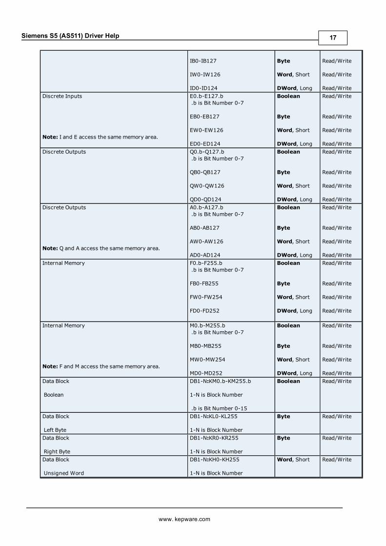
Siemens S5 (AS511) 100U-103 Address DescriptionsThe default data types for dynamically defined tags are shown in bold.
Address Type Range Type AccessDiscrete Inputs I0.b-I127.b
.b is Bit Number 0-7Boolean Read/Write
www. kepware.com
16
Siemens S5 (AS511) Driver Help
IB0-IB127
IW0-IW126
ID0-ID124
Byte
Word, Short
DWord, Long
Read/Write
Read/Write
Read/WriteDiscrete Inputs
Note: I and E access the samememory area.
E0.b-E127.b.b is Bit Number 0-7
EB0-EB127
EW0-EW126
ED0-ED124
Boolean
Byte
Word, Short
DWord, Long
Read/Write
Read/Write
Read/Write
Read/WriteDiscrete Outputs Q0.b-Q127.b
.b is Bit Number 0-7
QB0-QB127
QW0-QW126
QD0-QD124
Boolean
Byte
Word, Short
DWord, Long
Read/Write
Read/Write
Read/Write
Read/WriteDiscrete Outputs
Note: Q and A access the samememory area.
A0.b-A127.b.b is Bit Number 0-7
AB0-AB127
AW0-AW126
AD0-AD124
Boolean
Byte
Word, Short
DWord, Long
Read/Write
Read/Write
Read/Write
Read/WriteInternal Memory F0.b-F255.b
.b is Bit Number 0-7
FB0-FB255
FW0-FW254
FD0-FD252
Boolean
Byte
Word, Short
DWord, Long
Read/Write
Read/Write
Read/Write
Read/Write
Internal Memory
Note: F and M access the samememory area.
M0.b-M255.b.b is Bit Number 0-7
MB0-MB255
MW0-MW254
MD0-MD252
Boolean
Byte
Word, Short
DWord, Long
Read/Write
Read/Write
Read/Write
Read/WriteData Block
Boolean
DB1-N:KM0.b-KM255.b
1-N is Block Number
.b is Bit Number 0-15
Boolean Read/Write
Data Block
Left Byte
DB1-N:KL0-KL255
1-N is Block Number
Byte Read/Write
Data Block
Right Byte
DB1-N:KR0-KR255
1-N is Block Number
Byte Read/Write
Data Block
Unsigned Word
DB1-N:KH0-KH255
1-N is Block Number
Word, Short Read/Write
www. kepware.com
17
Siemens S5 (AS511) Driver Help
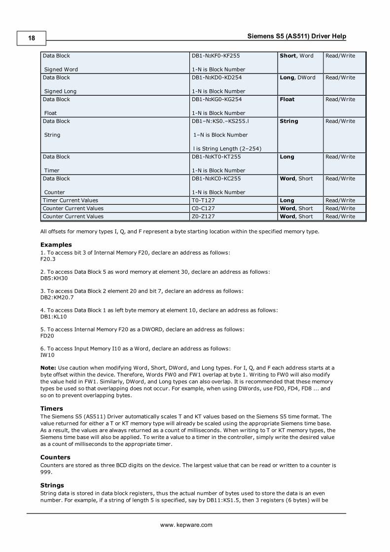
Data Block
Signed Word
DB1-N:KF0-KF255
1-N is Block Number
Short, Word Read/Write
Data Block
Signed Long
DB1-N:KD0-KD254
1-N is Block Number
Long, DWord Read/Write
Data Block
Float
DB1-N:KG0-KG254
1-N is Block Number
Float Read/Write
Data Block
String
DB1–N:KS0.–KS255.l
1–N is Block Number
l is String Length (2–254)
String Read/Write
Data Block
Timer
DB1-N:KT0-KT255
1-N is Block Number
Long Read/Write
Data Block
Counter
DB1-N:KC0-KC255
1-N is Block Number
Word, Short Read/Write
Timer Current Values T0-T127 Long Read/WriteCounter Current Values C0-C127 Word, Short Read/WriteCounter Current Values Z0-Z127 Word, Short Read/Write
All offsets for memory types I, Q, and F represent a byte starting location within the specified memory type.
Examples1. To access bit 3 of Internal Memory F20, declare an address as follows:F20.3
2. To access Data Block 5 as word memory at element 30, declare an address as follows:DB5:KH30
3. To access Data Block 2 element 20 and bit 7, declare an address as follows:DB2:KM20.7
4. To access Data Block 1 as left byte memory at element 10, declare an address as follows:DB1:KL10
5. To access Internal Memory F20 as a DWORD, declare an address as follows:FD20
6. To access Input Memory I10 as a Word, declare an address as follows:IW10
Note: Use caution when modifying Word, Short, DWord, and Long types. For I, Q, and F each address starts at abyte offset within the device. Therefore, Words FW0 and FW1 overlap at byte 1. Writing to FW0 will also modifythe value held in FW1. Similarly, DWord, and Long types can also overlap. It is recommended that these memorytypes be used so that overlapping does not occur. For example, when using DWords, use FD0, FD4, FD8 ... andso on to prevent overlapping bytes.
TimersThe Siemens S5 (AS511) Driver automatically scales T and KT values based on the Siemens S5 time format. Thevalue returned for either a T or KT memory type will already be scaled using the appropriate Siemens time base.As a result, the values are always returned as a count of milliseconds. When writing to T or KT memory types, theSiemens time base will also be applied. To write a value to a timer in the controller, simply write the desired valueas a count of milliseconds to the appropriate timer.
CountersCounters are stored as three BCD digits on the device. The largest value that can be read or written to a counter is999.
StringsString data is stored in data block registers, thus the actual number of bytes used to store the data is an evennumber. For example, if a string of length 5 is specified, say by DB11:KS1.5, then 3 registers (6 bytes) will be
www. kepware.com
18

Siemens S5 (AS511) Driver Help
used to store the string data. When writing strings shorter than the maximum specified length (5 in this exam-ple), a null terminator (0x00) will be added to the end of the string. When strings are read, the full range of reg-isters are read (3 in this example). Use of string tags with overlapping address ranges should be avoided due tothe effects of the null terminators.
Siemens S5 (AS511) 101U Address DescriptionsThe default data types for dynamically defined tags are shown in bold.
Address Type Range Type AccessDiscrete Inputs I0.b-I127.b
.b is Bit Number 0-7
IB0-IB127
IW0-IW126
ID0-ID124
Boolean
Byte
Word, Short
DWord, Long
Read/Write
Read/Write
Read/Write
Read/WriteDiscrete Inputs
Note: I and E access the samememory area.
E0.b-E127.b.b is Bit Number 0-7
EB0-EB127
EW0-EW126
ED0-ED124
Boolean
Byte
Word, Short
DWord, Long
Read/Write
Read/Write
Read/Write
Read/WriteDiscrete Outputs Q0.b-Q127.b
.b is Bit Number 0-7
QB0-QB127
QW0-QW126
QD0-QD124
Boolean
Byte
Word, Short
DWord, Long
Read/Write
Read/Write
Read/Write
Read/WriteDiscrete Outputs
Note: Q and A access the samememory area.
A0.b-A127.b.b is Bit Number 0-7
AB0-AB127
AW0-AW126
AD0-AD124
Boolean
Byte
Word, Short
DWord, Long
Read/Write
Read/Write
Read/Write
Read/WriteInternal Memory F0.b-F255.b
.b is Bit Number 0-7
FB0-FB255
FW0-FW254
FD0-FD252
Boolean
Byte
Word, Short
DWord, Long
Read/Write
Read/Write
Read/Write
Read/WriteInternal Memory
Note: F and M access the samememory area.
M0.b-M255.b.b is Bit Number 0-7
MB0-MB255
MW0-MW254
MD0-MD252
Boolean
Byte
Word, Short
DWord, Long
Read/Write
Read/Write
Read/Write
Read/WriteData Block
Boolean
DB1-N:KM0.b-KM255.b
1-N is Block Number
.b is Bit Number 0-15
Boolean Read/Write
Data Block DB1-N:KL0-KL255 Byte Read/Write
www. kepware.com
19
Siemens S5 (AS511) Driver Help
Left Byte 1-N is Block NumberData Block
Right Byte
DB1-N:KR0-KR255
1-N is Block Number
Byte Read/Write
Data Block
Unsigned Word
DB1-N:KH0-KH255
1-N is Block Number
Word, Short Read/Write
Data Block
Signed Word
DB1-N:KF0-KF255
1-N is Block Number
Short, Word Read/Write
Data Block
Signed Long
DB1-N:KD0-KD254
1-N is Block Number
Long, DWord Read/Write
Data Block
Float
DB1-N:KG0-KG254
1-N is Block Number
Float Read/Write
Data Block
String
DB1-N:KS0.l-KS255.l
1-N is Block Number
l is String Length (2-254)
String Read/Write
Data Block
Timer
DB1-N:KT0-KT255
1-N is Block Number
Long Read/Write
Data Block
Counter
DB1-N:KC0-KC255
1-N is Block Number
Word, Short Read/Write
Timer Current Values T0-T127 Long Read/WriteCounter Current Values C0-C127 Word, Short Read/WriteCounter Current Values Z0-Z127 Word, Short Read/Write
All offsets for memory types I, Q, and F represent a byte starting location within the specified memory type.
Examples1. To access bit 3 of Internal Memory F20, declare an address as follows:F20.3
2. To access Data Block 5 as word memory at element 30, declare an address as follows:DB5:KH30
3. To access Data Block 2 element 20 and bit 7, declare an address as follows:DB2:KM20.7
4. To access Data Block 1 as left byte memory at element 10, declare an address as follows:DB1:KL10
5. To access Internal Memory F20 as a DWORD, declare an address as follows:FD20
6. To access Input Memory I10 as a Word, declare an address as follows:IW10
Note: Use caution when modifying Word, Short, DWord, and Long types. For I, Q, and F each address starts at abyte offset within the device. Therefore, Words FW0 and FW1 overlap at byte 1. Writing to FW0 will also modifythe value held in FW1. Similarly, DWord, and Long types can also overlap. It is recommended that these memorytypes be used so that overlapping does not occur. For example, when using DWords, use FD0, FD4, FD8 ... andso on to prevent overlapping bytes.
TimersThe Siemens S5 (AS511) Driver automatically scales T and KT values based on the Siemens S5 time format. Thevalue returned for either a T or KT memory type will already be scaled using the appropriate Siemens time base.As a result, the values are always returned as a count of milliseconds. When writing to T or KT memory types, the
www. kepware.com
20

Siemens S5 (AS511) Driver Help
Siemens time base will also be applied. To write a value to a timer in the controller, simply write the desired valueas a count of milliseconds to the appropriate timer.
CountersCounters are stored as three BCD digits on the device. The largest value that can be read or written to a counter is999.
StringsString data is stored in data block registers, thus the actual number of bytes used to store the data is an evennumber. For example, if a string of length 5 is specified, say by DB11:KS1.5, then 3 registers (6 bytes) will beused to store the string data. When writing strings shorter than the maximum specified length (5 in this exam-ple), a null terminator (0x00) will be added to the end of the string. When strings are read, the full range of reg-isters are read (3 in this example). Use of string tags with overlapping address ranges should be avoided due tothe effects of the null terminators.
Siemens S5 (AS511) 115U-941 Address DescriptionsThe default data types for dynamically defined tags are shown in bold.
Address Type Range Type AccessDiscrete Inputs I0.b-I127.b
.b is Bit Number 0-7
IB0-IB127
IW0-IW126
ID0-ID124
Boolean
Byte
Word, Short
DWord, Long
Read/Write
Read/Write
Read/Write
Read/WriteDiscrete Inputs
Note: I and E access the samememory area.
E0.b-E127.b.b is Bit Number 0-7
EB0-EB127
EW0-EW126
ED0-ED124
Boolean
Byte
Word, Short
DWord, Long
Read/Write
Read/Write
Read/Write
Read/WriteDiscrete Outputs Q0.b-Q127.b
.b is Bit Number 0-7
QB0-QB127
QW0-QW126
QD0-QD124
Boolean
Byte
Word, Short
DWord, Long
Read/Write
Read/Write
Read/Write
Read/WriteDiscrete Outputs
Note: Q and A access the samememory area.
A0.b-A127.b.b is Bit Number 0-7
AB0-AB127
AW0-AW126
AD0-AD124
Boolean
Byte
Word, Short
DWord, Long
Read/Write
Read/Write
Read/Write
Read/WriteInternal Memory F0.b-F255.b
.b is Bit Number 0-7
FB0-FB255
FW0-FW254
FD0-FD252
Boolean
Byte
Word, Short
DWord, Long
Read/Write
Read/Write
Read/Write
Read/WriteInternal Memory M0.b-M255.b
.b is Bit Number 0-7
MB0-MB255
Boolean
Byte
Read/Write
Read/Write
www. kepware.com
21

Siemens S5 (AS511) Driver Help
Note: F and M access the samememory area.MW0-MW254
MD0-MD252
Word, Short
DWord, Long
Read/Write
Read/WriteData Block
Boolean
DB1-N:KM0.b-KM255.b
1-N is Block Number
.b is Bit Number 0-15
Boolean Read/Write
Data Block
Left Byte
DB1-N:KL0-KL255
1-N is Block Number
Byte Read/Write
Data Block
Right Byte
DB1-N:KR0-KR255
1-N is Block Number
Byte Read/Write
Data Block
Unsigned Word
DB1-N:KH0-KH255
1-N is Block Number
Word, Short Read/Write
Data Block
Signed Word
DB1-N:KF0-KF255
1-N is Block Number
Short, Word Read/Write
Data Block
Signed Long
DB1-N:KD0-KD254
1-N is Block Number
Long, DWord Read/Write
Data Block
Float
DB1-N:KG0-KG254
1-N is Block Number
Float Read/Write
Data Block
String
DB1-N:KS0.l-KS255.l
1-N is Block Number
l is String Length (2-254)
String Read/Write
Data Block
Timer
DB1-N:KT0-KT255
1-N is Block Number
Long Read/Write
Data Block
Counter
DB1-N:KC0-KC255
1-N is Block Number
Word, Short Read/Write
Timer Current Values T0-T127 Long Read/WriteCounter Current Values C0-C127 Word, Short Read/WriteCounter Current Values Z0-Z127 Word, Short Read/Write
All offsets for memory types I, Q, and F represent a byte starting location within the specified memory type.
Examples1. To access bit 3 of Internal Memory F20, declare an address as follows:F20.3
2. To access Data Block 5 as word memory at element 30, declare an address as follows:DB5:KH30
3. To access Data Block 2 element 20 and bit 7, declare an address as follows:DB2:KM20.7
4. To access Data Block 1 as left byte memory at element 10, declare an address as follows:DB1:KL10
5. To access Internal Memory F20 as a DWORD, declare an address as follows:FD20
6. To access Input Memory I10 as a Word, declare an address as follows:IW10
www. kepware.com
22

Siemens S5 (AS511) Driver Help
Note: Use caution when modifying Word, Short, DWord, and Long types. For I, Q, and F each address starts at abyte offset within the device. Therefore, Words FW0 and FW1 overlap at byte 1. Writing to FW0 will also modifythe value held in FW1. Similarly, DWord, and Long types can also overlap. It is recommended that these memorytypes be used so that overlapping does not occur. For example, when using DWords, use FD0, FD4, FD8 ... andso on to prevent overlapping bytes.
TimersThe Siemens S5 (AS511) Driver automatically scales T and KT values based on the Siemens S5 time format. Thevalue returned for either a T or KT memory type will already be scaled using the appropriate Siemens time base.As a result, the values are always returned as a count of milliseconds. When writing to T or KT memory types, theSiemens time base will also be applied. To write a value to a timer in the controller, simply write the desired valueas a count of milliseconds to the appropriate timer.
CountersCounters are stored as three BCD digits on the device. The largest value that can be read or written to a counter is999.
StringsString data is stored in data block registers, thus the actual number of bytes used to store the data is an evennumber. For example, if a string of length 5 is specified, say by DB11:KS1.5, then 3 registers (6 bytes) will beused to store the string data. When writing strings shorter than the maximum specified length (5 in this exam-ple), a null terminator (0x00) will be added to the end of the string. When strings are read, the full range of reg-isters are read (3 in this example). Use of string tags with overlapping address ranges should be avoided due tothe effects of the null terminators.
Siemens S5 (AS511) 115U-942 Address DescriptionsDefault data types for dynamically defined tags are shown in bold.
Address Type Range Type AccessDiscrete Inputs I0.b-I127.b
.b is Bit Number 0-7
IB0-IB127
IW0-IW126
ID0-ID124
Boolean
Byte
Word, Short
DWord, Long
Read/Write
Read/Write
Read/Write
Read/WriteDiscrete Inputs
Note: I and E access the samememory area.
E0.b-E127.b.b is Bit Number 0-7
EB0-EB127
EW0-EW126
ED0-ED124
Boolean
Byte
Word, Short
DWord, Long
Read/Write
Read/Write
Read/Write
Read/WriteDiscrete Outputs Q0.b-Q127.b
.b is Bit Number 0-7
QB0-QB127
QW0-QW126
QD0-QD124
Boolean
Byte
Word, Short
DWord, Long
Read/Write
Read/Write
Read/Write
Read/WriteDiscrete Outputs
Note: Q and A access the samememory area
A0.b-A127.b.b is Bit Number 0-7
AB0-AB127
AW0-AW126
AD0-AD124
Boolean
Byte
Word, Short
DWord, Long
Read/Write
Read/Write
Read/Write
Read/WriteInternal Memory F0.b-F255.b
.b is Bit Number 0-7Boolean Read/Write
www. kepware.com
23
Siemens S5 (AS511) Driver Help
FB0-FB255
FW0-FW254
FD0-FD252
Byte
Word, Short
DWord, Long
Read/Write
Read/Write
Read/WriteInternal Memory
Note: F and M access the samememory area
M0.b-M255.b.b is Bit Number 0-7
MB0-MB255
MW0-MW254
MD0-MD252
Boolean
Byte
Word, Short
DWord, Long
Read/Write
Read/Write
Read/Write
Read/WriteData Block
Boolean
DB1-N:KM0.b-KM255.b
1-N is Block Number
.b is Bit Number 0-15
Boolean Read/Write
Data Block
Left Byte
DB1-N:KL0-KL255
1-N is Block Number
Byte Read/Write
Data Block
Right Byte
DB1-N:KR0-KR255
1-N is Block Number
Byte Read/Write
Data Block
Unsigned Word
DB1-N:KH0-KH255
1-N is Block Number
Word, Short Read/Write
Data Block
Signed Word
DB1-N:KF0-KF255
1-N is Block Number
Short, Word Read/Write
Data Block
Signed Long
DB1-N:KD0-KD254
1-N is Block Number
Long, DWord Read/Write
Data Block
Float
DB1-N:KG0-KG254
1-N is Block Number
Float Read/Write
Data Block
String
DB1-N:KS0.l-KS255.l
1-N is Block Number
l is String Length (2-254)
String Read/Write
Data Block
Timer
DB1-N:KT0-KT255
1-N is Block Number
Long Read/Write
Data Block
Counter
DB1-N:KC0-KC255
1-N is Block Number
Word, Short Read/Write
Timer Current Values T0-T127 Long Read/WriteCounter Current Values C0-C127 Word, Short Read/WriteCounter Current Values Z0-Z127 Word, Short Read/Write
All offsets for memory types I, Q, and F represent a byte starting location within the specified memory type.
Examples1. To access bit 3 of Internal Memory F20, declare an address as follows:F20.3
2. To access Data Block 5 as word memory at element 30, declare an address as follows:DB5:KH30
3. To access Data Block 2 element 20 and bit 7, declare an address as follows:DB2:KM20.7
www. kepware.com
24

Siemens S5 (AS511) Driver Help
4. To access Data Block 1 as left byte memory at element 10, declare an address as follows:DB1:KL10
5. To access Internal Memory F20 as a DWORD, declare an address as follows:FD20
6. To access Input Memory I10 as a Word, declare an address as follows:IW10
Note: Use caution when modifying Word, Short, DWord, and Long types. For I, Q, and F each address starts at abyte offset within the device. Therefore, Words FW0 and FW1 overlap at byte 1. Writing to FW0 will also modifythe value held in FW1. Similarly, DWord, and Long types can also overlap. It is recommended that these memorytypes be used so that overlapping does not occur. For example, when using DWords, use FD0, FD4, FD8 ... andso on to prevent overlapping bytes.
TimersThe Siemens S5 (AS511) Driver automatically scales T and KT values based on the Siemens S5 time format. Thevalue returned for either a T or KT memory type will already be scaled using the appropriate Siemens time base.As a result, the values are always returned as a count of milliseconds. When writing to T or KT memory types, theSiemens time base will also be applied. To write a value to a timer in the controller, simply write the desired valueas a count of milliseconds to the appropriate timer.
CountersCounters are stored as three BCD digits on the device. The largest value that can be read or written to a counter is999.
StringsString data is stored in data block registers, thus the actual number of bytes used to store the data is an evennumber. For example, if a string of length 5 is specified, say by DB11:KS1.5, then 3 registers (6 bytes) will beused to store the string data. When writing strings shorter than the maximum specified length (5 in this exam-ple), a null terminator (0x00) will be added to the end of the string. When strings are read, the full range of reg-isters are read (3 in this example). Use of string tags with overlapping address ranges should be avoided due tothe effects of the null terminators.
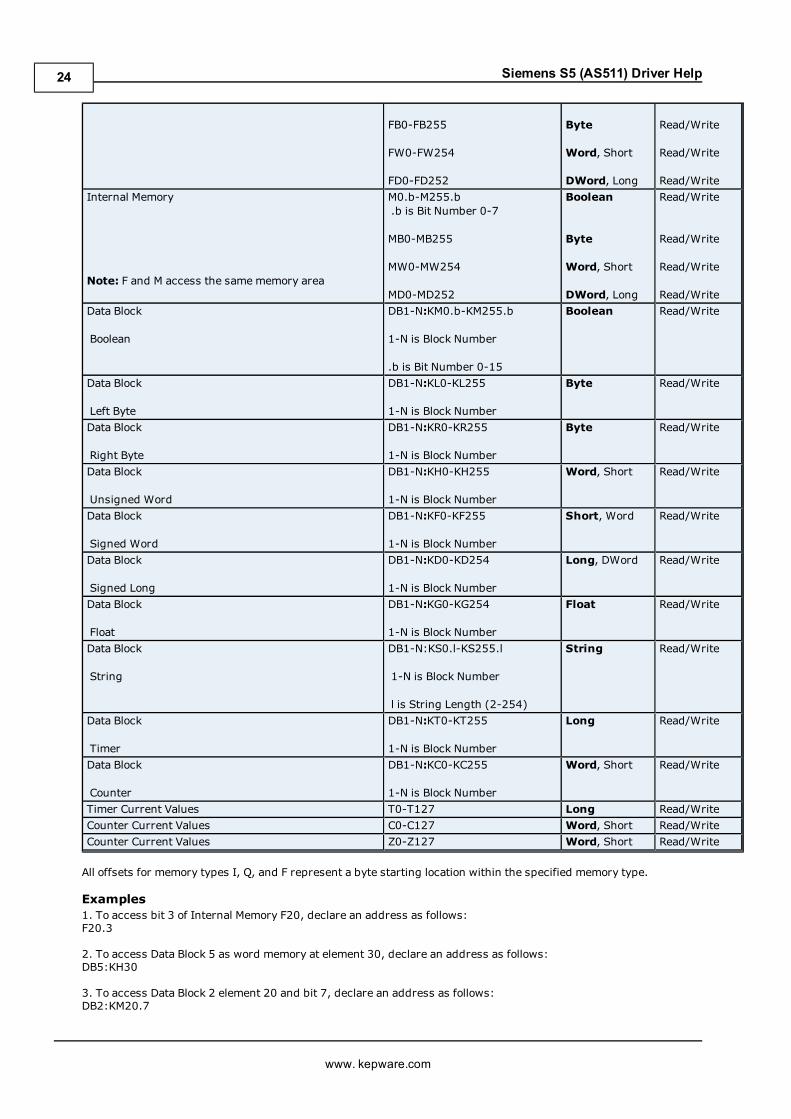
Siemens S5 (AS511) 115U-943 Address DescriptionsDefault data types for dynamically defined tags are shown in bold.
Address Type Range Type AccessDiscrete Inputs I0.b-I127.b
.b is Bit Number 0-7
IB0-IB127
IW0-IW126
ID0-ID124
Boolean
Byte
Word, Short
DWord, Long
Read/Write
Read/Write
Read/Write
Read/WriteDiscrete Inputs
Note: I and E access the samememory area.
E0.b-E127.b.b is Bit Number 0-7
EB0-EB127
EW0-EW126
ED0-ED124
Boolean
Byte
Word, Short
DWord, Long
Read/Write
Read/Write
Read/Write
Read/WriteDiscrete Outputs Q0.b-Q127.b
.b is Bit Number 0-7
QB0-QB127
QW0-QW126
QD0-QD124
Boolean
Byte
Word, Short
DWord, Long
Read/Write
Read/Write
Read/Write
Read/WriteDiscrete Outputs A0.b-A127.b Boolean Read/Write
www. kepware.com
25

Siemens S5 (AS511) Driver Help
Note: Q and A access the samememory area.
.b is Bit Number 0-7
AB0-AB127
AW0-AW126
AD0-AD124
Byte
Word, Short
DWord, Long
Read/Write
Read/Write
Read/WriteInternal Memory F0.b-F255.b
.b is Bit Number 0-7
FB0-FB255
FW0-FW254
FD0-FD252
Boolean
Byte
Word, Short
DWord, Long
Read/Write
Read/Write
Read/Write
Read/WriteInternal Memory
Note: F and M access the samememory area.
M0.b-M255.b.b is Bit Number 0-7
MB0-MB255
MW0-MW254
MD0-MD252
Boolean
Byte
Word, Short
DWord, Long
Read/Write
Read/Write
Read/Write
Read/WriteData Block
Boolean
DB1-N:KM0.b-KM255.b
1-N is Block Number
.b is Bit Number 0-15
Boolean Read/Write
Data Block
Left Byte
DB1-N:KL0-KL255
1-N is Block Number
Byte Read/Write
Data Block
Right Byte
DB1-N:KR0-KR255
1-N is Block Number
Byte Read/Write
Data Block
Unsigned Word
DB1-N:KH0-KH255
1-N is Block Number
Word, Short Read/Write
Data Block
Signed Word
DB1-N:KF0-KF255
1-N is Block Number
Short, Word Read/Write
Data Block
Signed Long
DB1-N:KD0-KD254
1-N is Block Number
Long, DWord Read/Write
Data Block
Float
DB1-N:KG0-KG254
1-N is Block Number
Float Read/Write
Data Block
String
DB1-N:KS0.l-KS255.l
1-N is Block Number
l is String Length (2-254)
String Read/Write
Data Block
Timer
DB1-N:KT0-KT255
1-N is Block Number
Long Read/Write
Data Block
Counter
DB1-N:KC0-KC255
1-N is Block Number
Word, Short Read/Write
Timer Current Values T0-T127 Long Read/WriteCounter Current Values C0-C127 Word, Short Read/WriteCounter Current Values Z0-Z127 Word, Short Read/Write
All offsets for memory types I, Q, and F represent a byte starting location within the specified memory type.
www. kepware.com
26

Siemens S5 (AS511) Driver Help
Examples1. To access bit 3 of Internal Memory F20, declare an address as follows:F20.3
2. To access Data Block 5 as word memory at element 30, declare an address as follows:DB5:KH30
3. To access Data Block 2 element 20 and bit 7, declare an address as follows:DB2:KM20.7
4. To access Data Block 1 as left byte memory at element 10, declare an address as follows:DB1:KL10
5. To access Internal Memory F20 as a DWORD, declare an address as follows:FD20
6. To access Input Memory I10 as a Word, declare an address as follows:IW10
Note: Use caution when modifying Word, Short, DWord, and Long types. For I, Q, and F each address starts at abyte offset within the device. Therefore, Words FW0 and FW1 overlap at byte 1. Writing to FW0 will also modifythe value held in FW1. Similarly, DWord, and Long types can also overlap. It is recommended that these memorytypes be used so that overlapping does not occur. For example, when using DWords, use FD0, FD4, FD8 ... andso on to prevent overlapping bytes.
TimersThe Siemens S5 (AS511) Driver automatically scales T and KT values based on the Siemens S5 time format. Thevalue returned for either a T or KT memory type will already be scaled using the appropriate Siemens time base.As a result, the values are always returned as a count of milliseconds. When writing to T or KT memory types, theSiemens time base will also be applied. To write a value to a timer in the controller, simply write the desired valueas a count of milliseconds to the appropriate timer.
CountersCounters are stored as three BCD digits on the device. The largest value that can be read or written to a counter is999.
StringsString data is stored in data block registers, thus the actual number of bytes used to store the data is an evennumber. For example, if a string of length 5 is specified, say by DB11:KS1.5, then 3 registers (6 bytes) will beused to store the string data. When writing strings shorter than the maximum specified length (5 in this exam-ple), a null terminator (0x00) will be added to the end of the string. When strings are read, the full range of reg-isters are read (3 in this example). Use of string tags with overlapping address ranges should be avoided due tothe effects of the null terminators.
Siemens S5 (AS511) 115U-944 Address DescriptionsThe default data types for dynamically defined tags are shown in bold.
Address Type Range Type AccessDiscrete Inputs I0.b-I127.b
.b is Bit Number 0-7
IB0-IB127
IW0-IW126
ID0-ID124
Boolean
Byte
Word, Short
DWord, Long
Read/Write
Read/Write
Read/Write
Read/WriteDiscrete Inputs
Note: I and E access the samememory area.
E0.b-E127.b.b is Bit Number 0-7
EB0-EB127
EW0-EW126
ED0-ED124
Boolean
Byte
Word, Short
DWord, Long
Read/Write
Read/Write
Read/Write
Read/Write
www. kepware.com
27

Siemens S5 (AS511) Driver Help
Discrete Outputs Q0.b-Q127.b.b is Bit Number 0-7
QB0-QB127
QW0-QW126
QD0-QD124
Boolean
Byte
Word, Short
DWord, Long
Read/Write
Read/Write
Read/Write
Read/WriteDiscrete Outputs
Note: Q and A access the samememory area.
A0.b-A127.b.b is Bit Number 0-7
AB0-AB127
AW0-AW126
AD0-AD124
Boolean
Byte
Word, Short
DWord, Long
Read/Write
Read/Write
Read/Write
Read/WriteInternal Memory F0.b-F255.b
.b is Bit Number 0-7
FB0-FB255
FW0-FW254
FD0-FD252
Boolean
Byte
Word, Short
DWord, Long
Read/Write
Read/Write
Read/Write
Read/WriteInternal Memory
Note: F and M access the samememory area.
M0.b-M255.b.b is Bit Number 0-7
MB0-MB255
MW0-MW254
MD0-MD252
Boolean
Byte
Word, Short
DWord, Long
Read/Write
Read/Write
Read/Write
Read/WriteData Block
Boolean
DB1-N:KM0.b-KM255.b
1-N is Block Number
.b is Bit Number 0-15
Boolean Read/Write
Data Block
Left Byte
DB1-N:KL0-KL255
1-N is Block Number
Byte Read/Write
Data Block
Right Byte
DB1-N:KR0-KR255
1-N is Block Number
Byte Read/Write
Data Block
Unsigned Word
DB1-N:KH0-KH255
1-N is Block Number
Word, Short Read/Write
Data Block
Signed Word
DB1-N:KF0-KF255
1-N is Block Number
Short, Word Read/Write
Data Block
Signed Long
DB1-N:KD0-KD254
1-N is Block Number
Long, DWord Read/Write
Data Block
Float
DB1-N:KG0-KG254
1-N is Block Number
Float Read/Write
Data Block
String
DB1-N:KS0.l-KS255.l
1-N is Block Number
l is String Length (2-254)
String Read/Write
www. kepware.com
28

Siemens S5 (AS511) Driver Help
Data Block
Timer
DB1-N:KT0-KT255
1-N is Block Number
Long Read/Write
Data Block
Counter
DB1-N:KC0-KC255
1-N is Block Number
Word, Short Read/Write
Timer Current Values T0-T127 Long Read/WriteCounter Current Values C0-C127 Word, Short Read/WriteCounter Current Values Z0-Z127 Word, Short Read/Write
All offsets for memory types I, Q, and F represent a byte starting location within the specified memory type.
Examples1. To access bit 3 of Internal Memory F20, declare an address as follows:F20.3
2. To access Data Block 5 as word memory at element 30, declare an address as follows:DB5:KH30
3. To access Data Block 2 element 20 and bit 7, declare an address as follows:DB2:KM20.7
4. To access Data Block 1 as left byte memory at element 10, declare an address as follows:DB1:KL10
5. To access Internal Memory F20 as a DWORD, declare an address as follows:FD20
6. To access Input Memory I10 as a Word, declare an address as follows:IW10
Note: Use caution when modifying Word, Short, DWord, and Long types. For I, Q, and F each address starts at abyte offset within the device. Therefore, Words FW0 and FW1 overlap at byte 1. Writing to FW0 will also modifythe value held in FW1. Similarly, DWord, and Long types can also overlap. It is recommended that these memorytypes be used so that overlapping does not occur. For example, when using DWords, use FD0, FD4, FD8 ... andso on to prevent overlapping bytes.
TimersThe Siemens S5 (AS511) Driver automatically scales T and KT values based on the Siemens S5 time format. Thevalue returned for either a T or KT memory type will already be scaled using the appropriate Siemens time base.As a result, the values are always returned as a count of milliseconds. When writing to T or KT memory types, theSiemens time base will also be applied. To write a value to a timer in the controller, simply write the desired valueas a count of milliseconds to the appropriate timer.
CountersCounters are stored as three BCD digits on the device. The largest value that can be read or written to a counter is999.
StringsString data is stored in data block registers, thus the actual number of bytes used to store the data is an evennumber. For example, if a string of length 5 is specified, say by DB11:KS1.5, then 3 registers (6 bytes) will beused to store the string data. When writing strings shorter than the maximum specified length (5 in this exam-ple), a null terminator (0x00) will be added to the end of the string. When strings are read, the full range of reg-isters are read (3 in this example). Use of string tags with overlapping address ranges should be avoided due tothe effects of the null terminators.
Siemens S5 (AS511) 115U-945 Address DescriptionsThe default data types for dynamically defined tags are shown in bold.
Address Type Range Type AccessDiscrete Inputs I0.b-I127.b
.b is Bit Number 0-7
IB0-IB127
Boolean
Byte
Read/Write
Read/Write
www. kepware.com
29
Siemens S5 (AS511) Driver Help
IW0-IW126
ID0-ID124
Word, Short
DWord, Long
Read/Write
Read/WriteDiscrete Inputs
Note: I and E access the samememory area.
E0.b-E127.b.b is Bit Number 0-7
EB0-EB127
EW0-EW126
ED0-ED124
Boolean
Byte
Word, Short
DWord, Long
Read/Write
Read/Write
Read/Write
Read/WriteDiscrete Outputs Q0.b-Q127.b
.b is Bit Number 0-7
QB0-QB127
QW0-QW126
QD0-QD124
Boolean
Byte
Word, Short
DWord, Long
Read/Write
Read/Write
Read/Write
Read/WriteDiscrete Outputs
Note: Q and A access the samememory area.
A0.b-A127.b.b is Bit Number 0-7
AB0-AB127
AW0-AW126
AD0-AD124
Boolean
Byte
Word, Short
DWord, Long
Read/Write
Read/Write
Read/Write
Read/WriteInternal Memory F0.b-F255.b
.b is Bit Number 0-7
FB0-FB255
FW0-FW254
FD0-FD252
Boolean
Byte
Word, Short
DWord, Long
Read/Write
Read/Write
Read/Write
Read/WriteInternal Memory
Note: F and M access the samememory area.
M0.b-M255.b.b is Bit Number 0-7
MB0-MB255
MW0-MW254
MD0-MD252
Boolean
Byte
Word, Short
DWord, Long
Read/Write
Read/Write
Read/Write
Read/WriteData BlockBoolean
DB1-N:KM0.b-KM255.b
1-N is Block Number
.b is Bit Number 0-15
Boolean Read/Write
Data Block
Right Byte
DB1-N:KL0-KL255
1-N is Block Number
Byte Read/Write
Data Block
Right Byte
DB1-N:KR0-KR255
1-N is Block Number
Byte Read/Write
Data Block
Unsigned Word
DB1-N:KH0-KH255
1-N is Block Number
Word, Short Read/Write
Data Block
Signed Word
DB1-N:KF0-KF255
1-N is Block Number
Short, Word Read/Write
Data Block
Signed Long
DB1-N:KD0-KD254
1-N is Block Number
Long, DWord Read/Write
www. kepware.com
30

Siemens S5 (AS511) Driver Help
Data Block
Float
DB1-N:KG0-KG254
1-N is Block Number
Float Read/Write
Data Block
String
DB1-N:KS0.l-KS255.l
1-N is Block Number
l is String Length (2-254)
String Read/Write
Data Block
Timer
DB1-N:KT0-KT255
1-N is Block Number
Long Read/Write
Data Block
Counter
DB1-N:KC0-KC255
1-N is Block Number
Word, Short Read/Write
Timer Current Values T0-T127 Long Read/WriteCounter Current Values C0-C127 Word, Short Read/WriteCounter Current Values Z0-Z127 Word, Short Read/Write
All offsets for memory types I, Q, and F represent a byte starting location within the specified memory type.
Examples1. To access bit 3 of Internal Memory F20, declare an address as follows:F20.3
2. To access Data Block 5 as word memory at element 30, declare an address as follows:DB5:KH30
3. To access Data Block 2 element 20 and bit 7, declare an address as follows:DB2:KM20.7
4. To access Data Block 1 as left byte memory at element 10, declare an address as follows:DB1:KL10
5. To access Internal Memory F20 as a DWORD, declare an address as follows:FD20
6. To access Input Memory I10 as a Word, declare an address as follows:IW10
Note: Use caution when modifying Word, Short, DWord, and Long types. For I, Q, and F each address starts at abyte offset within the device. Therefore, Words FW0 and FW1 overlap at byte 1. Writing to FW0 will also modifythe value held in FW1. Similarly, DWord, and Long types can also overlap. It is recommended that these memorytypes be used so that overlapping does not occur. For example, when using DWords, use FD0, FD4, FD8 ... andso on to prevent overlapping bytes.
TimersThe Siemens S5 (AS511) Driver automatically scales T and KT values based on the Siemens S5 time format. Thevalue returned for either a T or KT memory type will already be scaled using the appropriate Siemens time base.As a result, the values are always returned as a count of milliseconds. When writing to T or KT memory types, theSiemens time base will also be applied. To write a value to a timer in the controller, simply write the desired valueas a count of milliseconds to the appropriate timer.
CountersCounters are stored as three BCD digits on the device. The largest value that can be read or written to a counter is999.
StringsString data is stored in data block registers, thus the actual number of bytes used to store the data is an evennumber. For example, if a string of length 5 is specified, say by DB11:KS1.5, then 3 registers (6 bytes) will beused to store the string data. When writing strings shorter than the maximum specified length (5 in this exam-ple), a null terminator (0x00) will be added to the end of the string. When strings are read, the full range of reg-isters are read (3 in this example). Use of string tags with overlapping address ranges should be avoided due tothe effects of the null terminators.
www. kepware.com
31

Siemens S5 (AS511) Driver Help
Siemens S5 (AS511) 135U-921 Address DescriptionsThe default data types for dynamically defined tags are shown in bold.
Address Type Range Type AccessDiscrete Inputs I0.b-I511.b
.b is Bit Number 0-7
IB0-IB511
IW0-IW510
ID0-ID508
Boolean
Byte
Word, Short
DWord, Long
Read/Write
Read/Write
Read/Write
Read/WriteDiscrete Inputs
Note: I and E access the samememory area.
E0.b-E511.b.b is Bit Number 0-7
EB0-EB511
EW0-EW510
ED0-ED508
Boolean
Byte
Word, Short
DWord, Long
Read/Write
Read/Write
Read/Write
Read/WriteDiscrete Outputs Q0.b-Q511.b
.b is Bit Number 0-7
QB0-QB511
QW0-QW510
QD0-QD508
Boolean
Byte
Word, Short
DWord, Long
Read/Write
Read/Write
Read/Write
Read/WriteDiscrete Outputs
Note: Q and A access the samememory area.
A0.b-A511.b.b is Bit Number 0-7
AB0-AB511
AW0-AW510
AD0-AD508
Boolean
Byte
Word, Short
DWord, Long
Read/Write
Read/Write
Read/Write
Read/WriteInternal Memory F0.b-F255.b
.b is Bit Number 0-7
FB0-FB255
FW0-FW254
FD0-FD252
Boolean
Byte
Word, Short
DWord, Long
Read/Write
Read/Write
Read/Write
Read/WriteInternal Memory
Note: F and M access the samememory area.
M0.b-M255.b.b is Bit Number 0-7
MB0-MB255
MW0-MW254
MD0-MD252
Boolean
Byte
Word, Short
DWord, Long
Read/Write
Read/Write
Read/Write
Read/WriteData Block
Boolean
DB1-N:KM0.b-KM255.b
1-N is Block Number
.b is Bit Number 0-15
Boolean Read/Write
Data Block
Left Byte
DB1-N:KL0-KL255
1-N is Block Number
Byte Read/Write
www. kepware.com
32

Siemens S5 (AS511) Driver Help
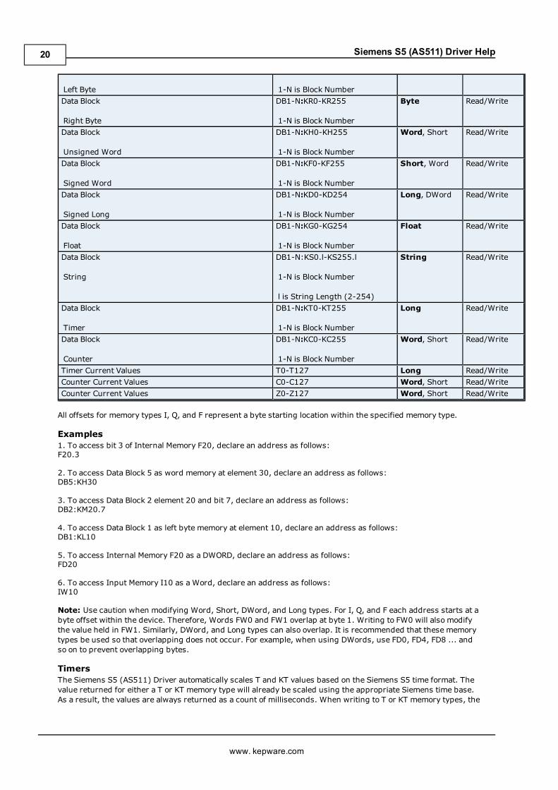
Data Block
Right Byte
DB1-N:KR0-KR255
1-N is Block Number
Byte Read/Write
Data Block
Unsigned Word
DB1-N:KH0-KH255
1-N is Block Number
Word, Short Read/Write
Data Block
Signed Word
DB1-N:KF0-KF255
1-N is Block Number
Short, Word Read/Write
Data Block
Signed Long
DB1-N:KD0-KD254
1-N is Block Number
Long, DWord Read/Write
Data Block
Float
DB1-N:KG0-KG254
1-N is Block Number
Float Read/Write
Data Block
String
DB1-N:KS0.l-KS255.l
1-N is Block Number
l is String Length (2-254)
String Read/Write
Data Block
Timer
DB1-N:KT0-KT255
1-N is Block Number
Long Read/Write
Data Block
Counter
DB1-N:KC0-KC255
1-N is Block Number
Word, Short Read/Write
Timer Current Values T0-T127 Long Read/WriteCounter Current Values C0-C127 Word, Short Read/WriteCounter Current Values Z0-Z127 Word, Short Read/Write
All offsets for memory types I, Q, and F represent a byte starting location within the specified memory type.
Examples1. To access bit 3 of Internal Memory F20, declare an address as follows:F20.3
2. To access Data Block 5 as word memory at element 30, declare an address as follows:DB5:KH30
3. To access Data Block 2 element 20 and bit 7, declare an address as follows:DB2:KM20.7
4. To access Data Block 1 as left byte memory at element 10, declare an address as follows:DB1:KL10
5. To access Internal Memory F20 as a DWORD, declare an address as follows:FD20
6. To access Input Memory I10 as a Word, declare an address as follows:IW10
Note: Use caution when modifying Word, Short, DWord, and Long types. For I, Q, and F each address starts at abyte offset within the device. Therefore, Words FW0 and FW1 overlap at byte 1. Writing to FW0 will also modifythe value held in FW1. Similarly, DWord, and Long types can also overlap. It is recommended that these memorytypes be used so that overlapping does not occur. For example, when using DWords, use FD0, FD4, FD8 ... andso on to prevent overlapping bytes.
TimersThe Siemens S5 (AS511) Driver automatically scales T and KT values based on the Siemens S5 time format. Thevalue returned for either a T or KT memory type will already be scaled using the appropriate Siemens time base.As a result, the values are always returned as a count of milliseconds. When writing to T or KT memory types, theSiemens time base will also be applied. To write a value to a timer in the controller, simply write the desired valueas a count of milliseconds to the appropriate timer.
Counters
www. kepware.com
33
Siemens S5 (AS511) Driver Help
Counters are stored as three BCD digits on the device. The largest value that can be read or written to a counter is999.
StringsString data is stored in data block registers, thus the actual number of bytes used to store the data is an evennumber. For example, if a string of length 5 is specified, say by DB11:KS1.5, then 3 registers (6 bytes) will beused to store the string data. When writing strings shorter than the maximum specified length (5 in this exam-ple), a null terminator (0x00) will be added to the end of the string. When strings are read, the full range of reg-isters are read (3 in this example). Use of string tags with overlapping address ranges should be avoided due tothe effects of the null terminators.
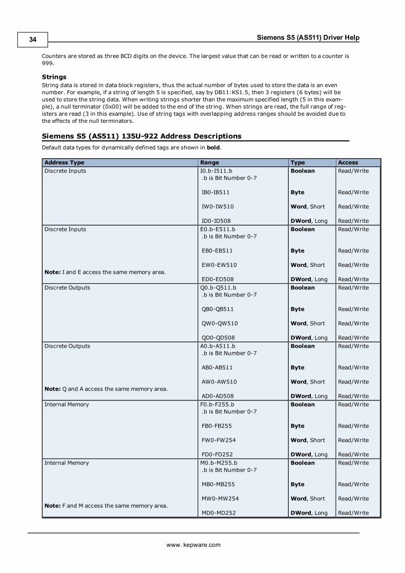
Siemens S5 (AS511) 135U-922 Address DescriptionsDefault data types for dynamically defined tags are shown in bold.
Address Type Range Type AccessDiscrete Inputs I0.b-I511.b
.b is Bit Number 0-7
IB0-IB511
IW0-IW510
ID0-ID508
Boolean
Byte
Word, Short
DWord, Long
Read/Write
Read/Write
Read/Write
Read/WriteDiscrete Inputs
Note: I and E access the samememory area.
E0.b-E511.b.b is Bit Number 0-7
EB0-EB511
EW0-EW510
ED0-ED508
Boolean
Byte
Word, Short
DWord, Long
Read/Write
Read/Write
Read/Write
Read/WriteDiscrete Outputs Q0.b-Q511.b
.b is Bit Number 0-7
QB0-QB511
QW0-QW510
QD0-QD508
Boolean
Byte
Word, Short
DWord, Long
Read/Write
Read/Write
Read/Write
Read/WriteDiscrete Outputs
Note: Q and A access the samememory area.
A0.b-A511.b.b is Bit Number 0-7
AB0-AB511
AW0-AW510
AD0-AD508
Boolean
Byte
Word, Short
DWord, Long
Read/Write
Read/Write
Read/Write
Read/WriteInternal Memory F0.b-F255.b
.b is Bit Number 0-7
FB0-FB255
FW0-FW254
FD0-FD252
Boolean
Byte
Word, Short
DWord, Long
Read/Write
Read/Write
Read/Write
Read/WriteInternal Memory
Note: F and M access the samememory area.
M0.b-M255.b.b is Bit Number 0-7
MB0-MB255
MW0-MW254
MD0-MD252
Boolean
Byte
Word, Short
DWord, Long
Read/Write
Read/Write
Read/Write
Read/Write
www. kepware.com
34

Siemens S5 (AS511) Driver Help
Data Block
Boolean
DB1-N:KM0.b-KM255.b
1-N is Block Number
.b is Bit Number 0-15
Boolean Read/Write
Data Block
Left Byte
DB1-N:KL0-KL255
1-N is Block Number
Byte Read/Write
Data Block
Right Byte
DB1-N:KR0-KR255
1-N is Block Number
Byte Read/Write
Data Block
Unsigned Word
DB1-N:KH0-KH255
1-N is Block Number
Word, Short Read/Write
Data Block
Signed Word
DB1-N:KF0-KF255
1-N is Block Number
Short, Word Read/Write
Data Block
Signed Long
DB1-N:KD0-KD254
1-N is Block Number
Long, DWord Read/Write
Data Block
Float
DB1-N:KG0-KG254
1-N is Block Number
Float Read/Write
Data Block
String
DB1-N:KS0.l-KS255.l
1-N is Block Number
l is String Length (2-254)
String Read/Write
Data Block
Timer
DB1-N:KT0-KT255
1-N is Block Number
Long Read/Write
Data Block
Counter
DB1-N:KC0-KC255
1-N is Block Number
Word, Short Read/Write
Timer Current Values T0-T127 Long Read/WriteCounter Current Values C0-C127 Word, Short Read/WriteCounter Current Values Z0-Z127 Word, Short Read/Write
All offsets for memory types I, Q, and F represent a byte starting location within the specified memory type.
Examples1. To access bit 3 of Internal Memory F20, declare an address as follows:F20.3
2. To access Data Block 5 as word memory at element 30, declare an address as follows:DB5:KH30
3. To access Data Block 2 element 20 and bit 7, declare an address as follows:DB2:KM20.7
4. To access Data Block 1 as left byte memory at element 10, declare an address as follows:DB1:KL10
5. To access Internal Memory F20 as a DWORD, declare an address as follows:FD20
6. To access Input Memory I10 as a Word, declare an address as follows:IW10
Note: Use caution when modifying Word, Short, DWord, and Long types. For I, Q, and F each address starts at abyte offset within the device. Therefore, Words FW0 and FW1 overlap at byte 1. Writing to FW0 will also modifythe value held in FW1. Similarly, DWord, and Long types can also overlap. It is recommended that these memorytypes be used so that overlapping does not occur. For example, when using DWords, use FD0, FD4, FD8 ... andso on to prevent overlapping bytes.
www. kepware.com
35

Siemens S5 (AS511) Driver Help
TimersThe Siemens S5 (AS511) Driver automatically scales T and KT values based on the Siemens S5 time format. Thevalue returned for either a T or KT memory type will already be scaled using the appropriate Siemens time base.As a result, the values are always returned as a count of milliseconds. When writing to T or KT memory types, theSiemens time base will also be applied. To write a value to a timer in the controller, simply write the desired valueas a count of milliseconds to the appropriate timer.
CountersCounters are stored as three BCD digits on the device. The largest value that can be read or written to a counter is999.
StringsString data is stored in data block registers, thus the actual number of bytes used to store the data is an evennumber. For example, if a string of length 5 is specified, say by DB11:KS1.5, then 3 registers (6 bytes) will beused to store the string data. When writing strings shorter than the maximum specified length (5 in this exam-ple), a null terminator (0x00) will be added to the end of the string. When strings are read, the full range of reg-isters are read (3 in this example). Use of string tags with overlapping address ranges should be avoided due tothe effects of the null terminators.
Siemens S5 (AS511) 135U-928 Address DescriptionsThe default data types for dynamically defined tags are shown in bold.
Address Type Range Type AccessDiscrete Inputs I0.b-I511.b
.b is Bit Number 0-7
IB0-IB511
IW0-IW510
ID0-ID508
Boolean
Byte
Word, Short
DWord, Long
Read/Write
Read/Write
Read/Write
Read/WriteDiscrete Inputs
Note: I and E access the samememory area.
E0.b-E511.b.b is Bit Number 0-7
EB0-EB511
EW0-EW510
ED0-ED508
Boolean
Byte
Word, Short
DWord, Long
Read/Write
Read/Write
Read/Write
Read/WriteDiscrete Outputs Q0.b-Q511.b
.b is Bit Number 0-7
QB0-QB511
QW0-QW510
QD0-QD508
Boolean
Byte
Word, Short
DWord, Long
Read/Write
Read/Write
Read/Write
Read/WriteDiscrete Outputs
Note: Q and A access the samememory area.
A0.b-A511.b.b is Bit Number 0-7
AB0-AB511
AW0-AW510
AD0-AD508
Boolean
Byte
Word, Short
DWord, Long
Read/Write
Read/Write
Read/Write
Read/WriteInternal Memory F0.b-F255.b
.b is Bit Number 0-7
FB0-FB255
FW0-FW254
FD0-FD252
Boolean
Byte
Word, Short
DWord, Long
Read/Write
Read/Write
Read/Write
Read/Write
www. kepware.com
36

Siemens S5 (AS511) Driver Help
Internal Memory
Note: F and M access the samememory area.
M0.b-M255.b.b is Bit Number 0-7
MB0-MB255
MW0-MW254
MD0-MD252
Boolean
Byte
Word, Short
DWord, Long
Read/Write
Read/Write
Read/Write
Read/WriteData Block
Boolean
DB1-N:KM0.b-KM255.b
1-N is Block Number
.b is Bit Number 0-15
Boolean Read/Write
Data Block
Left Byte
DB1-N:KL0-KL255
1-N is Block Number
Byte Read/Write
Data Block
Right Byte
DB1-N:KR0-KR255
1-N is Block Number
Byte Read/Write
Data Block
Unsigned Word
DB1-N:KH0-KH255
1-N is Block Number
Word, Short Read/Write
Data Block
Signed Word
DB1-N:KF0-KF255
1-N is Block Number
Short, Word Read/Write
Data Block
Signed Long
DB1-N:KD0-KD254
1-N is Block Number
Long, DWord Read/Write
Data Block
Float
DB1-N:KG0-KG254
1-N is Block Number
Float Read/Write
Data Block
String
DB1-N:KS0.l-KS255.l
1-N is Block Number
l is String Length (2-254)
String Read/Write
Data Block
Timer
DB1-N:KT0-KT255
1-N is Block Number
Long Read/Write
Data Block
Counter
DB1-N:KC0-KC255
1-N is Block Number
Word, Short Read/Write
Timer Current Values T0-T255 Long Read/WriteCounter Current Values C0-C255 Word, Short Read/WriteCounter Current Values Z0-Z255 Word, Short Read/Write
All offsets for memory types I, Q, and F represent a byte starting location within the specified memory type.
Examples1. To access bit 3 of Internal Memory F20, declare an address as follows:F20.3
2. To access Data Block 5 as word memory at element 30, declare an address as follows:DB5:KH30
3. To access Data Block 2 element 20 and bit 7, declare an address as follows:DB2:KM20.7
4. To access Data Block 1 as left byte memory at element 10, declare an address as follows:DB1:KL10
5. To access Internal Memory F20 as a DWORD, declare an address as follows:FD20
www. kepware.com
37
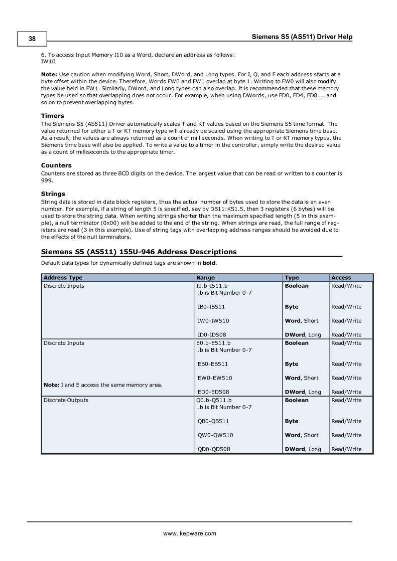
Siemens S5 (AS511) Driver Help
6. To access Input Memory I10 as a Word, declare an address as follows:IW10
Note: Use caution when modifying Word, Short, DWord, and Long types. For I, Q, and F each address starts at abyte offset within the device. Therefore, Words FW0 and FW1 overlap at byte 1. Writing to FW0 will also modifythe value held in FW1. Similarly, DWord, and Long types can also overlap. It is recommended that these memorytypes be used so that overlapping does not occur. For example, when using DWords, use FD0, FD4, FD8 ... andso on to prevent overlapping bytes.
TimersThe Siemens S5 (AS511) Driver automatically scales T and KT values based on the Siemens S5 time format. Thevalue returned for either a T or KT memory type will already be scaled using the appropriate Siemens time base.As a result, the values are always returned as a count of milliseconds. When writing to T or KT memory types, theSiemens time base will also be applied. To write a value to a timer in the controller, simply write the desired valueas a count of milliseconds to the appropriate timer.
CountersCounters are stored as three BCD digits on the device. The largest value that can be read or written to a counter is999.
StringsString data is stored in data block registers, thus the actual number of bytes used to store the data is an evennumber. For example, if a string of length 5 is specified, say by DB11:KS1.5, then 3 registers (6 bytes) will beused to store the string data. When writing strings shorter than the maximum specified length (5 in this exam-ple), a null terminator (0x00) will be added to the end of the string. When strings are read, the full range of reg-isters are read (3 in this example). Use of string tags with overlapping address ranges should be avoided due tothe effects of the null terminators.
Siemens S5 (AS511) 155U-946 Address DescriptionsDefault data types for dynamically defined tags are shown in bold.
Address Type Range Type AccessDiscrete Inputs I0.b-I511.b
.b is Bit Number 0-7
IB0-IB511
IW0-IW510
ID0-ID508
Boolean
Byte
Word, Short
DWord, Long
Read/Write
Read/Write
Read/Write
Read/WriteDiscrete Inputs
Note: I and E access the samememory area.
E0.b-E511.b.b is Bit Number 0-7
EB0-EB511
EW0-EW510
ED0-ED508
Boolean
Byte
Word, Short
DWord, Long
Read/Write
Read/Write
Read/Write
Read/WriteDiscrete Outputs Q0.b-Q511.b
.b is Bit Number 0-7
QB0-QB511
QW0-QW510
QD0-QD508
Boolean
Byte
Word, Short
DWord, Long
Read/Write
Read/Write
Read/Write
Read/Write
www. kepware.com
38

Siemens S5 (AS511) Driver Help
Discrete Outputs
Note: Q and A access the samememory area.
A0.b-A511.b.b is Bit Number 0-7
AB0-AB511
AW0-AW510
AD0-AD508
Boolean
Byte
Word, Short
DWord, Long
Read/Write
Read/Write
Read/Write
Read/WriteInternal Memory F0.b-F255.b
.b is Bit Number 0-7
FB0-FB255
FW0-FW254
FD0-FD252
Boolean
Byte
Word, Short
DWord, Long
Read/Write
Read/Write
Read/Write
Read/WriteInternal Memory
Note: F and M access the samememory area.
M0.b-M255.b.b is Bit Number 0-7
MB0-MB255
MW0-MW254
MD0-MD252
Boolean
Byte
Word, Short
DWord, Long
Read/Write
Read/Write
Read/Write
Read/WriteData Block
Boolean
DB1-N:KM0.b-KM255.b
1-N is Block Number
.b is Bit Number 0-15
Boolean Read/Write
Data Block
Left Byte
DB1-N:KL0-KL255
1-N is Block Number
Byte Read/Write
Data Block
Right Byte
DB1-N:KR0-KR255
1-N is Block Number
Byte Read/Write
Data Block
Unsigned Word
DB1-N:KH0-KH255
1-N is Block Number
Word, Short Read/Write
Data Block
Signed Word
DB1-N:KF0-KF255
1-N is Block Number
Short, Word Read/Write
Data Block
Signed Long
DB1-N:KD0-KD254
1-N is Block Number
Long, DWord Read/Write
Data Block
Float
DB1-N:KG0-KG254
1-N is Block Number
Float Read/Write
Data Block
String
DB1-N:KS0.l-KS255.l
1-N is Block Number
l is String Length (2-254)
String Read/Write
Data Block
Timer
DB1-N:KT0-KT255
1-N is Block Number
Long Read/Write
Data Block
Counter
DB1-N:KC0-KC255
1-N is Block Number
Word, Short Read/Write
Timer Current Values T0-T255 Long Read/WriteCounter Current Values C0-C255 Word, Short Read/WriteCounter Current Values Z0-Z255 Word, Short Read/Write
All offsets for memory types I, Q, and F represent a byte starting location within the specified memory type.
www. kepware.com
39

Siemens S5 (AS511) Driver Help
Examples1. To access bit 3 of Internal Memory F20, declare an address as follows:F20.3
2. To access Data Block 5 as word memory at element 30, declare an address as follows:DB5:KH30
3. To access Data Block 2 element 20 and bit 7, declare an address as follows:DB2:KM20.7
4. To access Data Block 1 as left byte memory at element 10, declare an address as follows:DB1:KL10
5. To access Internal Memory F20 as a DWORD, declare an address as follows:FD20
6. To access Input Memory I10 as a Word, declare an address as follows:IW10
Note:Use caution when modifying Word, Short, DWord, and Long types. For I, Q, and F each address starts at abyte offset within the device. Therefore, Words FW0 and FW1 overlap at byte 1. Writing to FW0 will also modifythe value held in FW1. Similarly, DWord, and Long types can also overlap. It is recommended that these memorytypes be used so that overlapping does not occur. For example, when using DWords, use FD0, FD4, FD8 ... andso on to prevent overlapping bytes.
TimersThe Siemens S5 (AS511) Driver automatically scales T and KT values based on the Siemens S5 time format. Thevalue returned for either a T or KT memory type will already be scaled using the appropriate Siemens time base.As a result, the values are always returned as a count of milliseconds. When writing to T or KT memory types, theSiemens time base will also be applied. To write a value to a timer in the controller, simply write the desired valueas a count of milliseconds to the appropriate timer.
CountersCounters are stored as three BCD digits on the device. The largest value that can be read or written to a counter is999.
StringsString data is stored in data block registers, thus the actual number of bytes used to store the data is an evennumber. For example, if a string of length 5 is specified, say by DB11:KS1.5, then 3 registers (6 bytes) will beused to store the string data. When writing strings shorter than the maximum specified length (5 in this exam-ple), a null terminator (0x00) will be added to the end of the string. When strings are read, the full range of reg-isters are read (3 in this example). Use of string tags with overlapping address ranges should be avoided due tothe effects of the null terminators.
Siemens S5 (AS511) 155U-947 Address DescriptionsThe default data types for dynamically defined tags are shown in bold.
Address Type Range Type AccessDiscrete Inputs I0.b-I511.b
.b is Bit Number 0-7
IB0-IB511
IW0-IW510
ID0-ID508
Boolean
Byte
Word, Short
DWord, Long
Read/Write
Read/Write
Read/Write
Read/Write
www. kepware.com
40

Siemens S5 (AS511) Driver Help
Discrete Inputs
Note: I and E access the samememory area.
E0.b-E511.b.b is Bit Number 0-7
EB0-EB511
EW0-EW510
ED0-ED508
Boolean
Byte
Word, Short
DWord, Long
Read/Write
Read/Write
Read/Write
Read/WriteDiscrete Outputs Q0.b-Q511.b
.b is Bit Number 0-7
QB0-QB511
QW0-QW510
QD0-QD508
Boolean
Byte
Word, Short
DWord, Long
Read/Write
Read/Write
Read/Write
Read/WriteDiscrete Outputs
Note: Q and A access the samememory area.
A0.b-A511.b.b is Bit Number 0-7
AB0-AB511
AW0-AW510
AD0-AD508
Boolean
Byte
Word, Short
DWord, Long
Read/Write
Read/Write
Read/Write
Read/Write
Internal Memory F0.b-F255.b.b is Bit Number 0-7
FB0-FB255
FW0-FW254
FD0-FD252
Boolean
Byte
Word, Short
DWord, Long
Read/Write
Read/Write
Read/Write
Read/WriteInternal Memory
Note: F and M access the samememory area.
M0.b-M255.b.b is Bit Number 0-7
MB0-MB255
MW0-MW254
MD0-MD252
Boolean
Byte
Word, Short
DWord, Long
Read/Write
Read/Write
Read/Write
Read/WriteData Block
Boolean
DB1-N:KM0.b-KM255.b
1-N is Block Number
.b is Bit Number 0-15
Boolean Read/Write
Data Block
Left Byte
DB1-N:KL0-KL255
1-N is Block Number
Byte Read/Write
Data Block
Right Byte
DB1-N:KR0-KR255
1-N is Block Number
Byte Read/Write
Data Block
Unsigned Word
DB1-N:KH0-KH255
1-N is Block Number
Word, Short Read/Write
Data Block
Signed Word
DB1-N:KF0-KF255
1-N is Block Number
Short, Word Read/Write
Data Block
Signed Long
DB1-N:KD0-KD254
1-N is Block Number
Long, DWord Read/Write
www. kepware.com
41

Siemens S5 (AS511) Driver Help
Data Block
Float
DB1-N:KG0-KG254
1-N is Block Number
Float Read/Write
Data Block
String
DB1-N:KS0.l-KS255.l
1-N is Block Number
l is String Length (2-254)
String Read/Write
Data Block
Timer
DB1-N:KT0-KT255
1-N is Block Number
Long Read/Write
Data Block
Counter
DB1-N:KC0-KC255
1-N is Block Number
Word, Short Read/Write
Timer Current Values T0-T255 Long Read/WriteCounter Current Values C0-C255 Word, Short Read/WriteCounter Current Values Z0-Z255 Word, Short Read/Write
All offsets for memory types I, Q, and F represent a byte starting location within the specified memory type.
Examples1. To access bit 3 of Internal Memory F20, declare an address as follows:F20.3
2. To access Data Block 5 as word memory at element 30, declare an address as follows:DB5:KH30
3. To access Data Block 2 element 20 and bit 7, declare an address as follows:DB2:KM20.7
4. To access Data Block 1 as left byte memory at element 10, declare an address as follows:DB1:KL10
5. To access Internal Memory F20 as a DWORD, declare an address as follows:FD20
6. To access Input Memory I10 as a Word, declare an address as follows:IW10
Note:Use caution when modifying Word, Short, DWord, and Long types. For I, Q, and F each address starts at abyte offset within the device. Therefore, Words FW0 and FW1 overlap at byte 1. Writing to FW0 will also modifythe value held in FW1. Similarly, DWord, and Long types can also overlap. It is recommended that these memorytypes be used so that overlapping does not occur. For example, when using DWords, use FD0, FD4, FD8 ... andso on to prevent overlapping bytes.
TimersThe Siemens S5 (AS511) Driver automatically scales T and KT values based on the Siemens S5 time format. Thevalue returned for either a T or KT memory type will already be scaled using the appropriate Siemens time base.As a result, the values are always returned as a count of milliseconds. When writing to T or KT memory types, theSiemens time base will also be applied. To write a value to a timer in the controller, simply write the desired valueas a count of milliseconds to the appropriate timer.
CountersCounters are stored as three BCD digits on the device. The largest value that can be read or written to a counter is999.
StringsString data is stored in data block registers, thus the actual number of bytes used to store the data is an evennumber. For example, if a string of length 5 is specified, say by DB11:KS1.5, then 3 registers (6 bytes) will beused to store the string data. When writing strings shorter than the maximum specified length (5 in this exam-ple), a null terminator (0x00) will be added to the end of the string. When strings are read, the full range of reg-isters are read (3 in this example). Use of string tags with overlapping address ranges should be avoided due tothe effects of the null terminators.
www. kepware.com
42

Siemens S5 (AS511) Driver Help
Error DescriptionsThe following error/warning messages may be generated. Click on the link for a description of the message.
Address ValidationAddress '<address>' is out of range for the specified device or registerArray support is not available for the specified address: '<address>'Data Type '<type>' is not valid for device address '<address>'Device address '<address>' contains a syntax errorDevice address '<address>' is not supported by model '<model name>'Missing address
Serial CommunicationsCommunications error on '<channel name>' [<error mask>]COMn does not existCOMn is in use by another applicationError opening COMnUnable to set comm parameters on COMn
Device Status MessagesDevice '<device name>' is not respondingUnable to write to '<address>' on device '<device name>'
Driver Warning MessagesData Block DB '<block number>' not defined in '<device name>' write operation has failedFailure reading device '<device name>' configurationProtocol Error-Number of bytes received = '<num bytes>' Expected = '<num bytes>'Requested Data Block DB'<block number>' not defined in '<device name>' block has been disabled
Address ValidationThe following error/warning messages may be generated. Click on the link for a description of the message.
Address ValidationAddress '<address>' is out of range for the specified device or registerArray support is not available for the specified address: '<address>'Data Type '<type>' is not valid for device address '<address>'Device address '<address>' contains a syntax errorDevice address '<address>' is not supported by model '<model name>'Missing address
Array support is not available for the specified address: '<address>'Error Type:Warning
Possible Cause:A tag address that has been specified dynamically contains an array reference for an address type that doesn'tsupport arrays.
Solution:Re-enter the address in the client application to remove the array reference or correct the address type.
Address '<address>' is out of range for the specified device or registerError Type:Warning
Possible Cause:A tag address that has been specified dynamically references a location that is beyond the range of supportedlocations for the device.
Solution:Verify the address is correct; if it is not, re-enter it in the client application.
www. kepware.com
43

Siemens S5 (AS511) Driver Help
Data Type '<type>' is not valid for device address '<address>'Error Type:Warning
Possible Cause:A tag address that has been specified dynamically has been assigned an invalid data type.
Solution:Modify the requested data type in the client application.
Device address '<address>' is not supported by model '<model name>'Error Type:Warning
Possible Cause:A tag address that has been specified dynamically references a location that is valid for the communications pro-tocol but not supported by the target device.
Solution:Verify that the address is correct; if it is not, re-enter it in the client application. Also verify that the selectedmodel name for the device is correct.
Device address '<address>' contains a syntax errorError Type:Warning
Possible Cause:A tag address that has been specified dynamically via DDE contains one or more invalid characters.
Solution:Re-enter the address in the client application.
Missing addressError Type:Warning
Possible Cause:A tag address that has been specified dynamically has no length.
Solution:Re-enter the address in the client application.
Serial CommunicationsThe following error/warning messages may be generated. Click on the link for a description of the message.
Serial CommunicationsCommunications error on '<channel name>' [<error mask>]COMn does not existCOMn is in use by another applicationError opening COMnUnable to set comm parameters on COMn
Communications error on '<channel name>' [<error mask>]Error Type:Serious
Error Mask Definitions:B = Hardware break detected.
www. kepware.com
44

Siemens S5 (AS511) Driver Help
F = Framing error.E = I/O error.O = Character buffer overrun.R = RX buffer overrun.P = Received byte parity error.T = TX buffer full.
Possible Cause:1. The serial connection between the device and the Host PC is bad.2. The communications parameters for the serial connection are incorrect.
Solution:1. Verify the cabling between the PC and the device.2. Verify that the specified communications parameters match those of the device.
COMn does not existError Type:Fatal
Possible Cause:The specified COM port is not present on the target computer.
Solution:Verify that the proper COM port has been selected.
COMn is in use by another applicationError Type:Fatal
Possible Cause:The serial port assigned to a device is being used by another application.
Solution:Verify that the correct port has been assigned to the channel.
Error opening COMnError Type:Fatal
Possible Cause:The specified COM port could not be opened due an internal hardware or software problem on the target com-puter.
Solution:Verify that the COM port is functional and may be accessed by other Windows applications.
Unable to set comm parameters on COMnError Type:Fatal
Possible Cause:The serial parameters for the specified COM port are not valid.
Solution:Verify the serial parameters and make any necessary changes.
Device Status MessagesThe following error/warning messages may be generated. Click on the link for a description of the message.
Device Status MessagesDevice '<device name>' is not responding
www. kepware.com
45

Siemens S5 (AS511) Driver Help
Unable to write to '<address>' on device '<device name>'
Device '<device name>' is not respondingError Type:Serious
Possible Cause:1. The serial connection between the device and the Host PC is broken.2. The communications parameters for the serial connection are incorrect.3. The named device may have been assigned an incorrect Network ID.4. The response from the device took longer to receive than the amount of time specified in the "Request Timeout"device setting.
Solution:1. Verify the cabling between the PC and the device.2. Verify the specified communications parameters match those of the device.3. Verify that the Network ID given to the named device matches that of the actual device.4. Increase the Request Timeout setting so that the entire response can be handled.
Unable to write to '<address>' on device '<device name>'Error Type:Serious
Possible Cause:1. The serial connection between the device and the Host PC is broken.2. The communications parameters for the serial connection are incorrect.3. The named device may have been assigned an incorrect Network ID.
Solution:1. Verify the cabling between the PC and the device.2. Verify that the specified communications parameters match those of the device.3. Verify that the Network ID given to the named device matches that of the actual device.
Driver Warning MessagesThe following error/warning messages may be generated. Click on the link for a description of the message.
Driver Warning MessagesData Block DB' <block number>' not defined in '<device name>' write operation has failedFailure reading device '<device name>' configurationProtocol Error-Number of bytes received = '<num bytes>' Expected = '<num bytes>'Requested Data Block DB'<block number>' not defined in '<device name>' block has been disabled
Data Block DB '<block number>' not defined in '<device name>' write oper-ation has failedError Type:Warning
Possible Cause:An attempt has been made to write to a nonexistent location in the specified device.
Solution:Verify the tags assigned to addresses in the specified range on the device and eliminate ones that referenceinvalid locations.
Failure reading device '<device name>' configurationError Type:Warning
Possible Cause:A device configuration transaction timed-out. Below are possible causes for this time-out:
www. kepware.com
46

Siemens S5 (AS511) Driver Help
1. The serial connection between the device and the Host PC is broken.2. The communications parameters for the serial port connection are incorrect.
Solution:1. Verify the cabling between the PC and the device.2. Verify that the correct baud rate and parity is specified for the named device.
Protocol Error-Number of bytes received = '<num bytes>' Expected = '<numbytes>'Error Type:Warning
Possible Cause:1. Misalignment of packets due to connection/disconnection between PC and device.2. There is bad cabling connecting the devices causing noise.
Solution:The driver will recover from this error without intervention. If this error occurs frequently, there may be an issuewith the cabling or the device itself.
Requested Data Block DB'<block number>' not defined in '<device name>'block has been disabledError Type:Warning
Possible Cause:An attempt has been made to reference a nonexistent location in the specified device.
Solution:Verify that the tags assigned to addresses in the specified range on the device and eliminate ones that referenceinvalid locations.
www. kepware.com
47

Siemens S5 (AS511) Driver Help
Index
A
Address '<address>' is out of range for the specified device or register 43Address Descriptions 8Address Validation 43Array support is not available for the specified address:'<address>' 43
B
Boolean 7Byte 7
C
Cable Connections 5Communications error on '<channel name>' [<error mask>] 44COMn does not exist 45COMn is in use by another application 45
D
Data Block DB '<block number>' not defined in '<device name>' write operation has failed 46Data Type '<type>' is not valid for device address '<address>' 44Data Types Description 7Device '<device name>' is not responding 46Device address '<address>' contains a syntax error 44Device address '<address>' is not supported by model '<model name>' 44Device ID 5Device Setup 5Device Status Messages 45Driver Warning Messages 46DWord 7
www. kepware.com
48

Siemens S5 (AS511) Driver Help
E
Error Descriptions 43Error opening COMn 45
F
Failure reading device '<device name>' configuration 46Float 7
L
Long 7
M
Master ID 5Missing address 44Modem Setup 6
N
Network 5
O
Overview 4
P
Protocol Error - Number of bytes received = '<num bytes>' Expected = '<num bytes>' 47
www. kepware.com
49

Siemens S5 (AS511) Driver Help
R
Requested Data Block DB'<block number>' not defined in '<device name>' block has beendisabled
47
S
Serial Communications 44Short 7Siemens S5 (AS511) 100U-100 Address Descriptions 12Siemens S5 (AS511) 100U-101 Address Descriptions 14Siemens S5 (AS511) 100U-103 Address Descriptions 16Siemens S5 (AS511) 101U Address Descriptions 19Siemens S5 (AS511) 115U-941 Address Descriptions 21Siemens S5 (AS511) 115U-942 Address Descriptions 23Siemens S5 (AS511) 115U-943 Address Descriptions 25Siemens S5 (AS511) 115U-944 Address Descriptions 27Siemens S5 (AS511) 115U - 945 Address Descriptions 29Siemens S5 (AS511) 135U-921 Address Descriptions 32Siemens S5 (AS511) 135U-922 Address Descriptions 34Siemens S5 (AS511) 135U-928 Address Descriptions 36Siemens S5 (AS511) 155U-947 Address Descriptions 40Siemens S5 (AS511) 155U - 946 Address Descriptions 38Siemens S5 (AS511) 90U Address Descriptions 8Siemens S5 (AS511) 95U Address Descriptions 10String 7
U
Unable to set comm parameters on COMn 45Unable to write tag '<address>' on device '<device name>' 46
W
Word 7
www. kepware.com
50


![FEIS TableOfContents[1]](https://img.pdfslide.us/doc/110x75/577d366b1a28ab3a6b9308e2/feis-tableofcontents1.jpg)