Embed Size (px)
Citation preview

www.sea.siemens.com
A white paper issued by Siemens. ©2010 Siemens Industry, Inc. All rights reserved.
Siemens Dynamic Arc Flash Reduction System and its application in low voltage switchgear
www.usa.siemens.com/switchgear
Prepared by: Allan Worthy, Product Manager Kevin Mullins, Consulting Business Developer Joseph Flocco, PE, Strategic Marketing Manager
The release of high arc fl ash energy is a growing concern within the electrical equipment community and among both designers and workers. Current research shows that up to 80% of reported electrical injuries are caused by an electrical arc1. This fact has spawned new requirements and standards in governing documents, such as in NFPA 70E® and the NEC®, which address the safety of workers, on and around energized electrical equipment. In response to safety needs and to fulfi ll these standards, Siemens has developed new technologies to address the issue of arc fl ash, and help lower released arc fl ash energy. This paper will explore the capabilities of the Dynamic Arc Flash Sentry4 (DAS), investigate an example case, and show the benefi ts of this technology in low voltage switchgear.
Siemens strongly recommends that all systems be de-energized when personnel are working on electrical equipment. However, in some circumstances qualifi ed professionals may need to access and work near energized equipment. For example, many troubleshooting operations, or work on critical applications, require that power remain on to complete the task. This is where many accidents occur and the risks and effects of an arc fl ash are the greatest. The Dynamic Arc Flash Sentry system is designed to greatly reduce the energy release of an arc fl ash while maintaining effi ciency of the loads on the low voltage switchgear. These loads could include motors, transformers, panels, motor control centers, or other distribution equipment.
Siemens Dynamic Arc Flash Sentry Technology uses a dual function setting of the ETU776 electronic trip unit when housed in the Siemens WL power circuit breaker. The trip unit has two parameters (A and B), that allow the operator to switch back and forth from a normal operating mode to a maintenance mode. The maintenance mode (Parameter B) reduces the instantaneous trip setting of the WL main breaker. By reducing the instantaneous region, the trip timing of the system is controlled, and can be reduced to clear a fault much sooner than the original operating time. This decreases the amount of energy available in an arc fl ash, which may allow a reduced level of personnel protective equipment to be worn around the equipment. It will also reduce the arc fl ash.
BUS 2Vs: 480 V
GRID
BUS 1Vs: 12470 V
500-1C-TH
WN
-S100 Feet#/P
H: 6
500-1C-TH
WN
-S100 Feet#/P
H: 6
500-1C-THWN-S100 Feet#/PH: 6
GEN 1Vs: 480 V
BUS 3Vs:480 V
1500-3-D12470/480 V1500 kVA
TX-4
SIEMENS- 1600SWGR 1Vs: 480 V
SIEMENS- 800
SIEMENS- 800
SIEMENS- 800
SIEMENS- 800
SIEMENS- 800
SIEMENS- 800WL WL WL WL WL WL
PANEL 1Vs: 480 V
250-1C-TH
WN
-S50 Feet#/P
H: 3
600 600 600 800 800 800
PANEL 2Vs: 480 V
250-1C-TH
WN
-S50 Feet#/P
H: 3
PANEL 3Vs: 480 V
250-1C-TH
WN
-S50 Feet#/P
H: 3
POWER PANEL 1Vs: 480 V
600-1C-TH
WN
-S50 Feet#/P
H: 2
POWER PANEL 2Vs: 480 V
600-1C-TH
WN
-S50 Feet#/P
H: 2
POWER PANEL 3Vs: 480 V
600-1C-TH
WN
-S50 Feet#/P
H: 2
WL 1600
2 White Paper | Dynamic Arc Flash Reduction System | March 1, 2010
A white paper issued by Siemens. ©2010 Siemens Industry, Inc. All rights reserved.
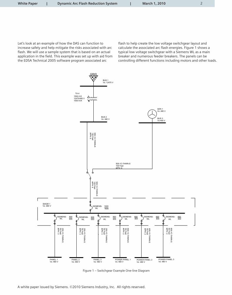
Let’s look at an example of how the DAS can function to increase safety and help mitigate the risks associated with arc fl ash. We will use a sample system that is based on an actual application in the fi eld. This example was set up with aid fromthe EDSA Technical 2005 software program associated arc
fl ash to help create the low voltage switchgear layout and calculate the associated arc fl ash energies. Figure 1 shows a typical low voltage switchgear with a Siemens WL as a main breaker and numerous feeder breakers. The panels can be controlling different functions including motors and other loads.
Figure 1 – Switchgear Example One-line Diagram
3
480 Volt Phase Time-Current Characteristic CurvesTCC 1Parameter Set A
02-15-201014:00:27
C:\EDSA2005\Projects\DAS SWGR whitepaper.PDC
.01
.11
1010
010
00Ti
me
in S
econ
ds
.5 1 10 100 1000 10000Current in Amperes X 100
SWGR 1 Main SIEMENS WLL ETU 776 LSIG WLL 1600A 1600 Amp
SWGR 1 800A FEEDER SIEMENS WLL ETU 776 LSIG WLL 800A 800 Amp
DLA: 1600Man.: SIEMENSType: WLLSize: WLL 1600ATrip: ETU 776 LSIGMax A/Plug/Setting: 1600 / 1600
SWGR 1
DLA: 1600Man.: SIEMENSType: WLLSize: WLL 800ATrip: ETU 776 LSIGMax A/Plug/Setting: 800 / 800
PANEL 1
White Paper | Dynamic Arc Flash Reduction System | March 1, 2010
A white paper issued by Siemens. ©2010 Siemens Industry, Inc. All rights reserved.
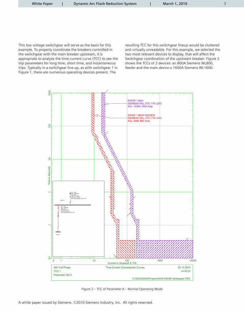
This low voltage switchgear will serve as the basis for this example. To properly coordinate the breakers controlled in the switchgear with the main breaker upstream, it is appropriate to analyze the time current curve (TCC) to see the trip parameters for long time, short time, and instantaneous trips. Typically in a switchgear line up, as with switchgear 1 in Figure 1, there are numerous operating devices present. The
resulting TCC for this switchgear lineup would be cluttered and virtually unreadable. For this example, we selected the two most relevant devices to display, that will affect the Switchgear coordination of the upstream breaker. Figure 2 shows the TCCs of 2 devices: an 800A Siemens WL800, feeder and the main device a 1600A Siemens WL1600.
Figure 2 – TCC of Parameter A – Normal Operating Mode
4 White Paper | Dynamic Arc Flash Reduction System | March 1, 2010
A white paper issued by Siemens. ©2010 Siemens Industry, Inc. All rights reserved.
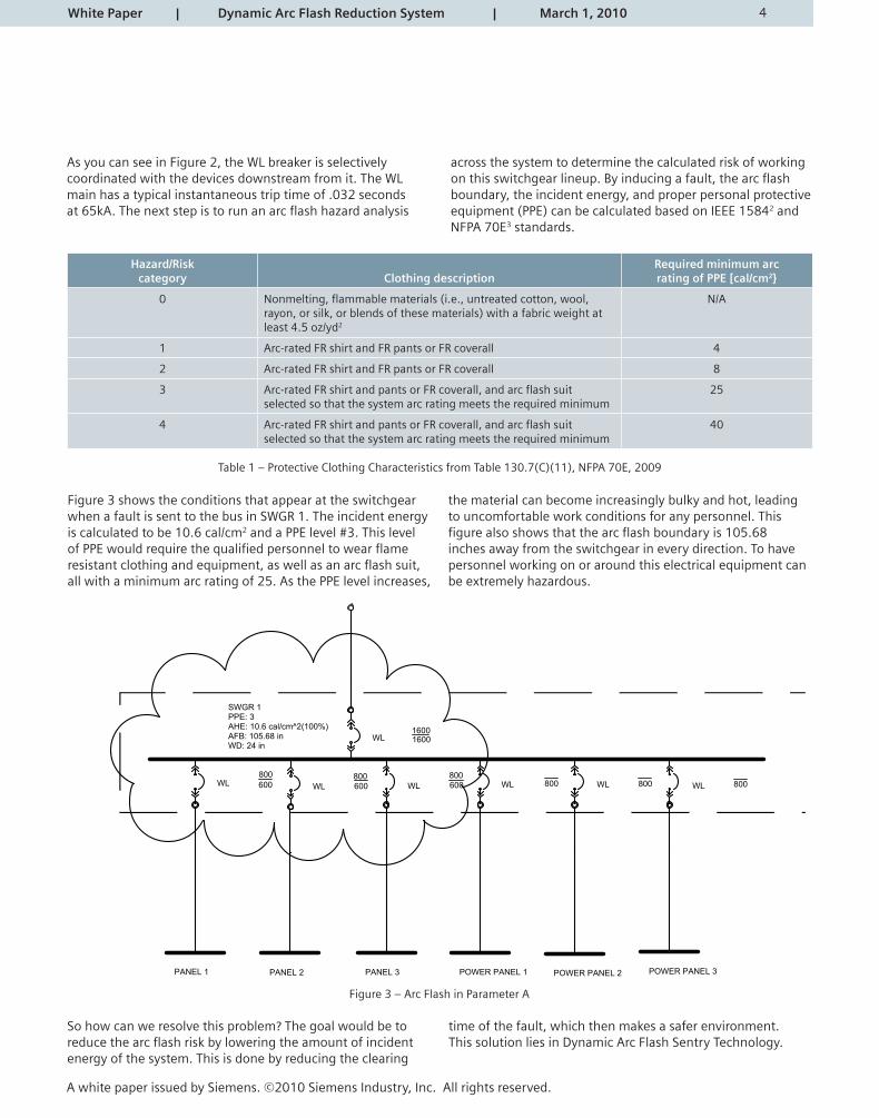
As you can see in Figure 2, the WL breaker is selectively coordinated with the devices downstream from it. The WL main has a typical instantaneous trip time of .032 seconds at 65kA. The next step is to run an arc fl ash hazard analysis
across the system to determine the calculated risk of working on this switchgear lineup. By inducing a fault, the arc fl ash boundary, the incident energy, and proper personal protective equipment (PPE) can be calculated based on IEEE 15842 and NFPA 70E3 standards.
Hazard/Riskcategory Clothing description
Required minimum arcrating of PPE [cal/cm2}
0 Nonmelting, fl ammable materials (i.e., untreated cotton, wool, rayon, or silk, or blends of these materials) with a fabric weight at least 4.5 oz/yd2
N/A
1 Arc-rated FR shirt and FR pants or FR coverall 4
2 Arc-rated FR shirt and FR pants or FR coverall 8
3 Arc-rated FR shirt and pants or FR coverall, and arc fl ash suit selected so that the system arc rating meets the required minimum
25
4 Arc-rated FR shirt and pants or FR coverall, and arc fl ash suit selected so that the system arc rating meets the required minimum
40
Table 1 – Protective Clothing Characteristics from Table 130.7(C)(11), NFPA 70E, 2009
Figure 3 shows the conditions that appear at the switchgear when a fault is sent to the bus in SWGR 1. The incident energy is calculated to be 10.6 cal/cm2 and a PPE level #3. This level of PPE would require the qualifi ed personnel to wear fl ame resistant clothing and equipment, as well as an arc fl ash suit, all with a minimum arc rating of 25. As the PPE level increases,
the material can become increasingly bulky and hot, leading to uncomfortable work conditions for any personnel. This fi gure also shows that the arc fl ash boundary is 105.68 inches away from the switchgear in every direction. To have personnel working on or around this electrical equipment can be extremely hazardous.
So how can we resolve this problem? The goal would be to reduce the arc fl ash risk by lowering the amount of incident energy of the system. This is done by reducing the clearing
time of the fault, which then makes a safer environment. This solution lies in Dynamic Arc Flash Sentry Technology.
SWGR 1PPE: 3AHE: 10.6 cal/cm^2(100%)AFB: 105.68 inWD: 24 in
WL WL WL WL WL WL
PANEL 1
600 600 600 800 800 800
PANEL 2 PANEL 3 POWER PANEL 1 POWER PANEL 2 POWER PANEL 3
WL 1600
800 800 800
1600
Figure 3 – Arc Flash in Parameter A
5 White Paper | Dynamic Arc Flash Reduction System | March 1, 2010
A white paper issued by Siemens. ©2010 Siemens Industry, Inc. All rights reserved.
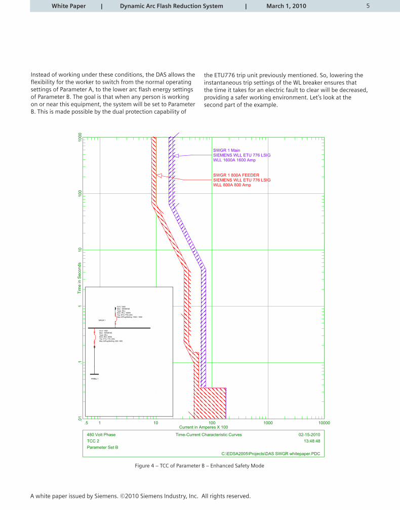
Instead of working under these conditions, the DAS allows the fl exibility for the worker to switch from the normal operating settings of Parameter A, to the lower arc fl ash energy settings of Parameter B. The goal is that when any person is working on or near this equipment, the system will be set to Parameter B. This is made possible by the dual protection capability of
the ETU776 trip unit previously mentioned. So, lowering the instantaneous trip settings of the WL breaker ensures that the time it takes for an electric fault to clear will be decreased, providing a safer working environment. Let’s look at the second part of the example.
480 Volt Phase Time-Current Characteristic CurvesTCC 2Parameter Set B
02-15-201013:48:48
C:\EDSA2005\Projects\DAS SWGR whitepaper.PDC
.01
.11
1010
010
00Ti
me
in S
econ
ds
.5 1 10 100 1000 10000Current in Amperes X 100
SWGR 1 Main SIEMENS WLL ETU 776 LSIG WLL 1600A 1600 Amp
SWGR 1 800A FEEDER SIEMENS WLL ETU 776 LSIG WLL 800A 800 Amp
DLA: 1600Man.: SIEMENSType: WLLSize: WLL 1600ATrip: ETU 776 LSIGMax A/Plug/Setting: 1600 / 1600
SWGR 1
DLA: 1600Man.: SIEMENSType: WLLSize: WLL 800ATrip: ETU 776 LSIGMax A/Plug/Setting: 800 / 800
PANEL 1
Figure 4 – TCC of Parameter B – Enhanced Safety Mode
6 White Paper | Dynamic Arc Flash Reduction System | March 1, 2010
A white paper issued by Siemens. ©2010 Siemens Industry, Inc. All rights reserved.
When switching from Parameter A to Parameter B, each of the settings is kept the same in the switchgear, except the instantaneous trip setting of the WL main breaker. The TCC for Parameter B is displayed in Figure 4. As can be seen, the WL main overlaps the WL feeder breaker in the instantaneous region, which was lowered to 5kA, while the other regions remain coordinated appropriately. This provides another example of the fl exibility of the ETU 776 trip unit in the Dynamic Arc Flash system.
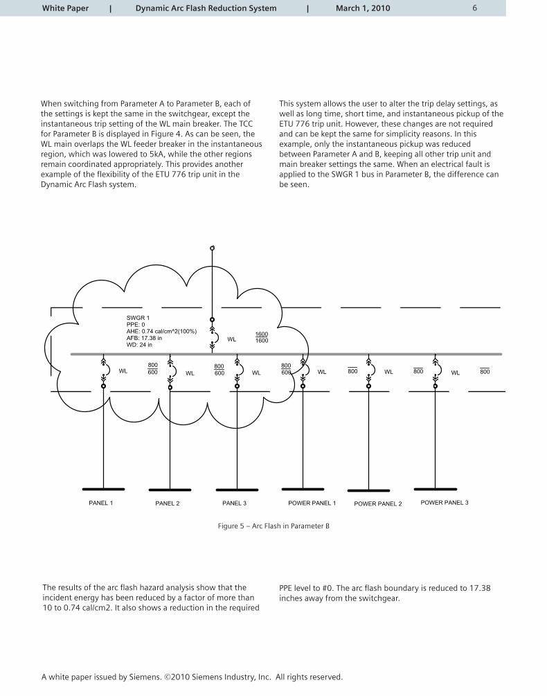
This system allows the user to alter the trip delay settings, as well as long time, short time, and instantaneous pickup of the ETU 776 trip unit. However, these changes are not required and can be kept the same for simplicity reasons. In this example, only the instantaneous pickup was reduced between Parameter A and B, keeping all other trip unit and main breaker settings the same. When an electrical fault is applied to the SWGR 1 bus in Parameter B, the difference can be seen.
SWGR 1PPE: 0AHE: 0.74 cal/cm^2(100%)AFB: 17.38 inWD: 24 in
WL WL WL WL WL WL
PANEL 1
600 600 600 800 800 800
PANEL 2 PANEL 3 POWER PANEL 1 POWER PANEL 2 POWER PANEL 3
WL 1600
800 800 800
1600
Figure 5 – Arc Flash in Parameter B
The results of the arc fl ash hazard analysis show that the incident energy has been reduced by a factor of more than10 to 0.74 cal/cm2. It also shows a reduction in the required
PPE level to #0. The arc fl ash boundary is reduced to 17.38inches away from the switchgear.
sevruC citsiretcarahC tnerruC-emiTesahP tloV 084
TCC 1
Parameter Set A
02-15-2010
14:00:27
C:\EDSA2005\Projects\DAS SWGR whitepaper.PDC
0001001
011
1.10.
Tim
e in
Sec
onds
0000100010010115.Current in Amperes X 100
SWGR 1 Main SIE MENS WLL ETU 776 LS IG WLL 1600A 1600 Amp
SWGR 1 800A F E E DER SIE MENS WLL ETU 776 LS IG WLL 800A 800 Amp
DLA: 1600Man.: SIEMENSType: WLLSize: WLL 1600ATrip: ETU 776 LSIGMax A/Plug/Setting: 1600 / 1600
SWGR 1
DLA: 1600Man.: SIEMENSType: WLLSize: WLL 800ATrip: ETU 776 LSIGMax A/Plug/Setting: 800 / 800
PANEL 1
Properly coordinated main and feeder device
sevruC citsiretcarahC tnerruC-emiTesahP tloV 084
TCC 2
Parameter Set B
02-15-2010
13:48:48
C:\EDSA2005\Projects\DAS SWGR whitepaper.PDC
0001001
011
1.10.
Tim
e in
Sec
onds
0000100010010115.Current in Amperes X 100
SWGR 1 Main SIE MENS WLL ETU 776 LS IG WLL 1600A 1600 Amp
SWGR 1 800A F E E DER SIE MENS WLL ETU 776 LS IG WLL 800A 800 Amp
DLA: 1600Man.: SIEMENSType: WLLSize: WLL 1600ATrip: ETU 776 LSIGMax A/Plug/Setting: 1600 / 1600
SWGR 1
DLA: 1600Man.: SIEMENSType: WLLSize: WLL 800ATrip: ETU 776 LSIGMax A/Plug/Setting: 800 / 800
PANEL 1
Main adjusted to reduce calculated arc energy
7
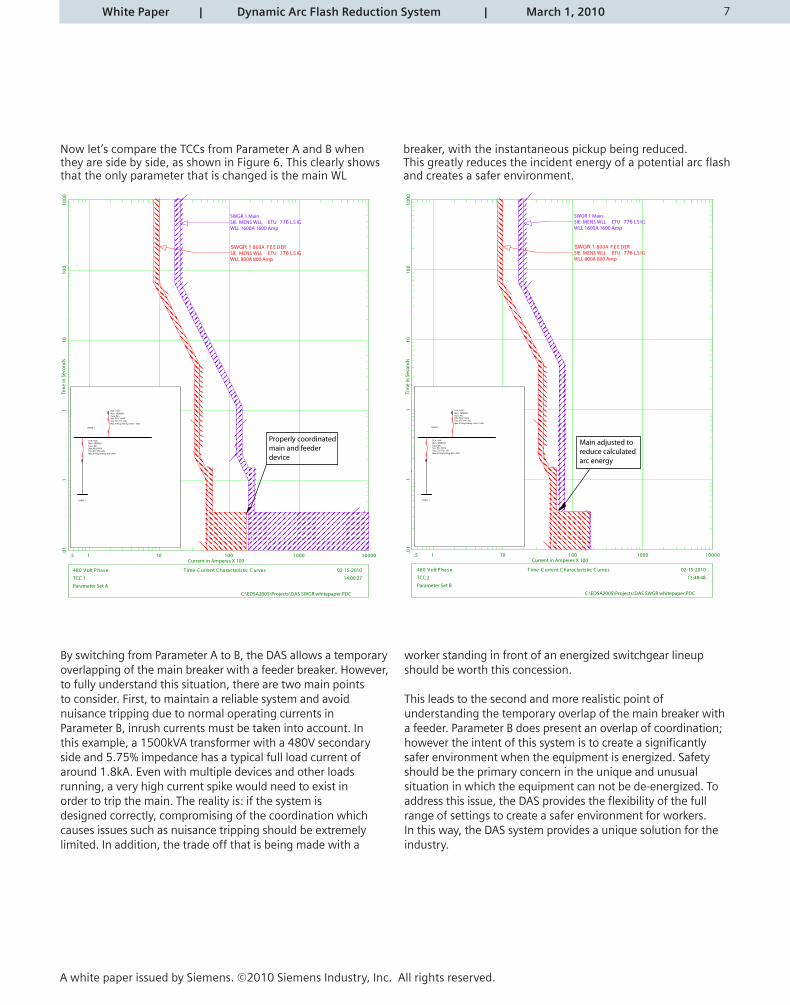
Now let’s compare the TCCs from Parameter A and B when they are side by side, as shown in Figure 6. This clearly shows that the only parameter that is changed is the main WL
breaker, with the instantaneous pickup being reduced. This greatly reduces the incident energy of a potential arc fl ash and creates a safer environment.
By switching from Parameter A to B, the DAS allows a temporary overlapping of the main breaker with a feeder breaker. However, to fully understand this situation, there are two main points to consider. First, to maintain a reliable system and avoid nuisance tripping due to normal operating currents in Parameter B, inrush currents must be taken into account. In this example, a 1500kVA transformer with a 480V secondary side and 5.75% impedance has a typical full load current of around 1.8kA. Even with multiple devices and other loadsrunning, a very high current spike would need to exist inorder to trip the main. The reality is: if the system is designed correctly, compromising of the coordination which causes issues such as nuisance tripping should be extremely limited. In addition, the trade off that is being made with a
worker standing in front of an energized switchgear lineup should be worth this concession.
This leads to the second and more realistic point ofunderstanding the temporary overlap of the main breaker witha feeder. Parameter B does present an overlap of coordination;however the intent of this system is to create a signifi cantlysafer environment when the equipment is energized. Safetyshould be the primary concern in the unique and unusualsituation in which the equipment can not be de-energized. Toaddress this issue, the DAS provides the fl exibility of the fullrange of settings to create a safer environment for workers.In this way, the DAS system provides a unique solution for theindustry.
White Paper | Dynamic Arc Flash Reduction System | March 1, 2010
A white paper issued by Siemens. ©2010 Siemens Industry, Inc. All rights reserved.
8
The Dynamic Arc Flash Sentry has been available in low voltage switchgear for some time. This technology can also be employed in Siemens switchboards, busway and motor control centers. Siemens is listening to its customers and meeting the highest industry standards. By offering a system that has the fl exibility to actually reduce the amount of arc fl ash incident energy without forcing customers to choose reliability over safety, the Dynamic Arc Flash System is addressing the diffi cult challenges related to electrical worker safety.
References:
1 National Technology Transfer, Inc. NFPA 70E/ Arc Flash: Electrical Safety. Edition 3.1.
2 IEEE Std 1584 -2002.
3 NFPA 70E: Standard for Electrical Safety in the Workplace. 2009 Edition.
4 ”Dynamic Arc-Flash Sentry” by Ray Clark. Siemens Technical Journal.
White Paper | Dynamic Arc Flash Reduction System | March 1, 2010
A white paper issued by Siemens. ©2010 Siemens Industry, Inc. All rights reserved.
www.usa.siemens.com/switchgearAll rights reserved. All trademarks use are owned by Siemens or their respective owners.© 2010 Siemens Industry, Inc.NFPA® and NEC® are registered trademarks of the National Fire Protection Association
Siemens Industry, Inc.Building Technologies Division5400 Triangle ParkwayNorcross, GA 300921-800-964-4114LVWP-DASSM-0810 Printed in USA