Embed Size (px)
Citation preview

Siemens LV 1 · 2010
19Overvoltage Protection Devices
19/122 Lightning arresters, type 1 19/123 Combination surge arresters, type 1
and type 219/124 Surge arresters, type 2 19/127 Surge arresters, type 319/128 Accessories for surge arresters19/129 Surge arresters for measuring and
control technology
Socket Outlets19/131 5TE6 8 socket outlets
Three-Phase Measuring Devices
19/133 7KT1 30 multimeters19/135 7KT1 31, 7KT1 34, 7KT1 35 multi-
counters19/137 7KT1 39 LAN couplers19/139 7KT1 5 E-counters19/140 7KT1 2 current transformers19/140 7KT9 0 measuring selector switches
Single-Phase Measuring Devices
19/141 7KT1 53, 7KT1 14 E-counters19/142 7KT1 11, 7KT1 12 digital measuring
devices19/142 7KT1 0 analog measuring devices19/143 7KT5 8 time and pulse counters19/144 7KT5 5, 7KT5 6 time counters for front
mounting
For Austria there is a separate catalog "BETA Low-Voltage Circuit Protection", with special products according to Austrian regulations.
Note:More devices from the BETA low-volt-age circuit protection range can be found in the Catalog ET B1 · 2010. You can download the up-to-date catalog from www.siemens.com/e-installation-catalogs.
BETA Low-Voltage Circuit Protection
19/2 Introduction
Miniature Circuit Breakers19/4 Miniature circuit breakers, 5SP and 5SY19/21 Miniature circuit breakers with plug-in termi-
nals, 5SJ6 . . .-.KS19/23 Miniature circuit breakers 1 + N in 1 MW,
5SY6 019/25 Additional components19/31 Busbars19/39 Miniature circuit breakers according to
UL 489 and IEC, 5SJ4 . . .-.HG 19/45 Circuit breaker terminals, 5SK9
Residual Current Protective Devices19/47 RCCBs, type A, 5SM319/51 SIQUENCE, universal current-sensitive
RCCBs type B and type B+, 5SM3 and 5SU1
19/54 Additional components19/55 RC units, type A, 5SM219/58 RCBOs, type A, 5SU119/61 Busbars19/63 Accessories
Low-Voltage Fuse Systems19/64 NEOZED fuse systems19/70 DIAZED fuse systems19/76 3NW cylindrical fuse systems19/79 3NW. ...-0HG Class CC fuse systems19/81 5ST2, 5ST3 busbars for fuse systems19/86 3NA, 3ND LV HRC fuse links19/94 3NX1 LV HRC signal detectors19/95 3NH LV HRC fuse basesCh.17 3NP1 LV HRC fuse switch disconnectorsCh.17 3NP5 LV HRC fuse switch disconnectors for
extended technical requirements
SITOR Semiconductor Fuses19/101 SITOR, LV HRC design19/109 SITOR, cylindrical fuse design19/111 SILIZED, NEOZED and DIAZED design
SR60 Busbar Systems19/112 Distribution board components19/116 Built-in components19/120 Mounting components
© Siemens AG 2010

BETA Low-Voltage Circuit Protection
Introduction
19/2 Siemens LV 1 · 2010
19
■ Overview
Miniature circuit breakers Miniature circuit breakers with plug-in terminal
Miniature circuit breakers 1 + N in 1 MW
Miniature circuit breakers according to UL 489 and IEC
Circuit breaker terminals
5SP4, 5SP5, 5SY4, 5SY5, 5SY6, 5SY7, 5SY8 5SJ6 . . .-.KS 5SY6 0 5SJ4 . . .-.HG 5SK9
Miniature circuit breakersTripping characteristic A, B, C, D B, C B, C B, C, D --
Rated current A 0.3 ... 125 10 ... 20 2 ... 40 0.3 ... 63 0.5 ... 10
Rated switching capacity
kA 6, 10, 15, 25 6 6 14/10 --
NEOZED fuse systems
DIAZED fuse systems
Cylindrical fuse systems
Class CC fuse system
LV HRC fuse links
LV HRC signal detectors
LV HRC fuse bases
5SE2, 5SG 5SA ... 5SD, 5SF, 5SH
3NW6, 3NW7, 3NW8
3NW1, 3NW23NW3, 3NW7
3NA, 3ND 3NX 3NH
Low-Voltage Fuse SystemsOperational classes gG gG gG, aM Slow/quick/slow,
current limitinggG, aM -- --
Rated voltage V AC V DC
400 250
500/690/750 500/600/750
400/500 600 150/300
400/500/690 250/440
690 600
690 250/440
Rated current range A 2 ... 100 2 ... 100 0.5 ... 100 0.6 ... 30 2 ... 1250 -- 160 ... 1250
Lightning arresters, type 1 Combination surge arresters, type 1 and type 2
Surge arresters, type 2 Surge arresters, type 3
5SD7 5SD7 5SD7 5SD7
Overvoltage protection devicesRated voltage V AC 230/400 230/400 230 ... 415 24 ... 400
Rated arrester voltage V AC 350 350 260 ... 350 24 ... 230
Discharge capacity kA 25/100 25/100 15/30; 20/40 1 ... 3
Multimeters Multicounters LAN couplers E-counters E-counters instabus KNX
Current transformers
Measuring selector switches
7KT1 30 7KT1 31, 7KT1 34, 7KT1 35
7KT1 39 7KT1 5 7KT1 1 7KT1 2 7KT9 0
Three-phase measuring devicesApplication Display of 23
electrical mea-sured values for switchgear assemblies, infeed or out-going feeders.
Display of 35 elec-trical measured values and con-sumption values in switchgear assem-blies, infeed or outgoing feeders.
Up-to-date consumption data of the multimeter available worldwide over LAN data com-munication.
Measurement of consumption data and plant capacity utilization in three-phase systems of system components, offices or holiday apartments.
Straight-through transformers for installation in distribution boards and non-contact measuring of primary currents.
For switching over the phases for voltmeters and ammeters
© Siemens AG 2010

19
BETA Low-Voltage Circuit Protection
Introduction
19/3Siemens LV 1 · 2010
RCCBs, type A
SIQUENCE, universal current-sensitive RCCBs, type B and type B+
RC units, type A
RCBOs, type A
5SM35SM3, 5SU1 5SM2 5SU1
Residual current protective devicesTypes of current Type A Type B Type A Type A
Rated current A 16 ... 125 16 ... 125 0.3 ... 100 6 ... 125
Rated residual current mA 10 ... 1000 30 ... 500 10 ... 1000 10 ... 300
SITOR, LV HRC design
SITOR, cylindrical fuse design
SILIZED, NEOZED and DIAZED design
3NC, 3NE 3NC 5SE1, 5SD
SITOR Semiconductor FusesOperational classes aR, gR, gS aR gR
Rated voltage V AC V DC
500 ... 2500 700
600/660/690 400/700
400/500 250/500
Rated current range A 16 ... 1600 1 ... 100 10 ... 100
Distribution board components
Built-in components Mounting components Socket outlets
8GK, 8JH, 8JK, 8US 5SF, 5SG, 5SH 5SH, 8US 5TE6 8
SR60 busbar systems Socket outletsApplication Busbars, busbar sup-
ports and coversNEOZED/DIAZED bus-mounting bases, NEOZED bus-mounting switch disconnectors
Bases, blanking cov-ers, edges
Application Power supply for maintenance of distribution boards
E-counters Digital measuring devices
Analog measuring devices Time and pulse counters
Time counters for front mounting
7KT1 53 7KT1 14
7KT1 11, 7KT1 12 7KT1 0 7KT5 8 7KT5 5, 7KT5 6
Single-phase measuring devicesApplication Measuring of kWh in
single-phase networksMeasuring of voltages and currents with large three-digit LED displays
Measuring of voltages and currents for monitoring input and output currents
For monitoring operat-ing hours and starting operations for plan-ning preventative main-tenance tasks and preventing sudden shutdowns
For monitoring operat-ing hours and starting operations for plan-ning preventative main-tenance tasks and preventing sudden shutdowns
© Siemens AG 2010

BETA ProtectingMiniature Circuit Breakers (MCBs)Miniature circuit breakers,5SP and 5SY
19/4 Siemens LV 1 · 2010
19
■ Overview
MCBs are used to protect plants in buildings and for industrial applications. The devices can be used as main control switches for the disconnection or isolation of plants.
For industrial applications and in plant engineering, miniature circuit breakers can be supplemented with additional compo-nents, such as auxiliary switches, fault signal contacts, shunt re-leases, undervoltage releases, remote-controlled mechanisms and RC units.
The devices are approved for worldwide use according to IEC standards for systems up to 250/440 V AC. 60 V DC per pole is permitted in DC systems.
For North America, we also have additional certification accord-ing to UL 1077 for use as "supplementary protectors" in systems up to AC 480Y/277 V. For use in ship building, the devices also have numerous certifications according to shipping classifica-tions; BV, DNV, GL and LRS. For further information, please refer to the section "Configuration".
■ Benefits
• The infeed can be either from the top or the bottom as the ter-minals are identical.
• Clear and visible conductor connection that can be easily checked in front of the busbar.
• Large and easily accessible wiring space enables easy inser-tion of conductor in the terminal.
• Integrated movable terminal covers located at the cable en-tries ensure the terminals are fully insulated when the screws are tightened.
• The effective touch protection when grasping the device con-siderably exceeds the requirements of BGV A3 (labor safety specification).
• Manual snap-on fixing and release systems that require no tools enable fast assembly and disassembly of MCBs.
• Marked labeling field on all modular installation devices for uniform, quick and easy identification.
• The MCBs can be quickly and easily removed from the busbar assembly by hand if connections need to be changed.
• Time saving if parts need to be replaced because the busbars no longer need to be freed from the adjacent devices.
© Siemens AG 2010

19
BETA ProtectingMiniature Circuit Breakers (MCBs)
Miniature circuit breakers,5SP and 5SY
19/5Siemens LV 1 · 2010
• Double terminal chambers enable 2 conductors of different cross-section to be accommodated (up to 10 mm2 in the bot-tom chamber and 35 mm2 in the top chamber).
• Adapted handle locking device for 5SY, 5SJ and 5SP minia-ture circuit breakers. Suitable for locks of 3 mm to 6 mm diam-eter.
© Siemens AG 2010

BETA ProtectingMiniature Circuit Breakers (MCBs)Miniature circuit breakers,5SP and 5SY
19/6 Siemens LV 1 · 2010
19
* You can order this quantity or a multiple thereof.
■ Selection and ordering data
Characteristic B
In MW DT Order No. Priceper PU
PU PS* PG Weightper PU
approx.
A Unit(s) Unit(s) kg
MCBs 6000 A
1P, 230/400 V AC
2 1 B 5SY6 102-6 1 1 002 0.1654 B 5SY6 104-6 1 1 002 0.1656 } 5SY6 106-6 1 1/12 002 0.165
10 } 5SY6 110-6 1 1/12 002 0.16513 A 5SY6 113-6 1 1/12 002 0.16516 } 5SY6 116-6 1 1/12 002 0.165
20 A 5SY6 120-6 1 1/12 002 0.16525 A 5SY6 125-6 1 1/12 002 0.16532 A 5SY6 132-6 1 1/12 002 0.165
40 B 5SY6 140-6 1 1 002 0.16550 B 5SY6 150-6 1 1 002 0.16563 B 5SY6 163-6 1 1 002 0.165
1P+N, 230 V AC
6 2 A 5SY6 506-6 1 1 002 0.33010 A 5SY6 510-6 1 1 002 0.33013 A 5SY6 513-6 1 1/6 002 0.330
16 A 5SY6 516-6 1 1/6 002 0.33020 B 5SY6 520-6 1 1 002 0.33025 B 5SY6 525-6 1 1 002 0.330
32 B 5SY6 532-6 1 1 002 0.33040 C 5SY6 540-6 1 1 002 0.33050 C 5SY6 550-6 1 1 002 0.33063 C 5SY6 563-6 1 1 002 0.330
2P, 400 V AC
6 2 A 5SY6 206-6 1 1/6 002 0.33010 A 5SY6 210-6 1 1/6 002 0.33013 B 5SY6 213-6 1 1 002 0.330
16 A 5SY6 216-6 1 1/6 002 0.33020 B 5SY6 220-6 1 1 002 0.33025 B 5SY6 225-6 1 1 002 0.330
32 A 5SY6 232-6 1 1 002 0.33040 B 5SY6 240-6 1 1 002 0.33050 C 5SY6 250-6 1 1 002 0.33063 C 5SY6 263-6 1 1 002 0.330
3P, 400 V AC
6 3 A 5SY6 306-6 1 1 002 0.49510 A 5SY6 310-6 1 1/4 002 0.49513 B 5SY6 313-6 1 1 002 0.495
16 } 5SY6 316-6 1 1/4 002 0.49520 A 5SY6 320-6 1 1 002 0.49525 A 5SY6 325-6 1 1 002 0.495
32 A 5SY6 332-6 1 1/4 002 0.49540 A 5SY6 340-6 1 1 002 0.49550 B 5SY6 350-6 1 1 002 0.49563 B 5SY6 363-6 1 1 002 0.495
3P+N, 400 V AC
6 4 B 5SY6 606-6 1 1 002 0.66010 B 5SY6 610-6 1 1 002 0.66013 B 5SY6 613-6 1 1 002 0.660
16 A 5SY6 616-6 1 1 002 0.66020 A 5SY6 620-6 1 1 002 0.66025 B 5SY6 625-6 1 1 002 0.660
32 B 5SY6 632-6 1 1 002 0.66040 C 5SY6 640-6 1 1 002 0.66050 C 5SY6 650-6 1 1 002 0.66063 C 5SY6 663-6 1 1 002 0.660
4P, 400 V AC
6 4 C 5SY6 406-6 1 1 002 0.66010 B 5SY6 410-6 1 1 002 0.66013 C 5SY6 413-6 1 1 002 0.660
16 A 5SY6 416-6 1 1 002 0.66020 A 5SY6 420-6 1 1 002 0.66025 A 5SY6 425-6 1 1 002 0.660
32 B 5SY6 432-6 1 1 002 0.66040 B 5SY6 440-6 1 1 002 0.66050 B 5SY6 450-6 1 1 002 0.66063 B 5SY6 463-6 1 1 002 0.660
6 0003
© Siemens AG 2010

19
BETA ProtectingMiniature Circuit Breakers (MCBs)
Miniature circuit breakers,5SP and 5SY
19/7Siemens LV 1 · 2010* You can order this quantity or a multiple thereof.
Characteristic C Characteristic D
In MW DT Order No. Priceper PU
PG DT Order No. Priceper PU
PU PS* PG Weightper PU
approx.
A Unit(s) Unit(s) kg
MCBs 6000 A
1P, 230/400 V AC
0.3 1 A 5SY6 114-7 003 C 5SY6 114-8 1 1 004 0.1650.5 A 5SY6 105-7 003 A 5SY6 105-8 1 1 004 0.1651 } 5SY6 101-7 003 A 5SY6 101-8 1 1 004 0.165
1.6 A 5SY6 115-7 003 C 5SY6 115-8 1 1 004 0.1472 } 5SY6 102-7 003 A 5SY6 102-8 1 1/12 004 0.1653 A 5SY6 103-7 003 A 5SY6 103-8 1 1 004 0.165
4 } 5SY6 104-7 003 A 5SY6 104-8 1 1 004 0.1656 } 5SY6 106-7 003 A 5SY6 106-8 1 1/12 004 0.1658 A 5SY6 108-7 003 A 5SY6 108-8 1 1 004 0.165
10 } 5SY6 110-7 003 A 5SY6 110-8 1 1 004 0.16513 A 5SY6 113-7 003 A 5SY6 113-8 1 1 004 0.16516 } 5SY6 116-7 003 A 5SY6 116-8 1 1 004 0.165
20 } 5SY6 120-7 003 A 5SY6 120-8 1 1 004 0.16525 } 5SY6 125-7 003 A 5SY6 125-8 1 1 004 0.16532 } 5SY6 132-7 003 B 5SY6 132-8 1 1 004 0.165
40 A 5SY6 140-7 003 B 5SY6 140-8 1 1 004 0.16550 A 5SY6 150-7 003 B 5SY6 150-8 1 1 004 0.16563 A 5SY6 163-7 003 B 5SY6 163-8 1 1 004 0.165
1P+N, 230 V AC
0.3 2 B 5SY6 514-7 003 C 5SY6 514-8 1 1 004 0.3300.5 A 5SY6 505-7 003 B 5SY6 505-8 1 1 004 0.3301 A 5SY6 501-7 003 C 5SY6 501-8 1 1 004 0.330
1.6 B 5SY6 515-7 003 B 5SY6 515-8 1 1 004 0.3302 A 5SY6 502-7 003 B 5SY6 502-8 1 1 004 0.3303 A 5SY6 503-7 003 B 5SY6 503-8 1 1 004 0.330
4 A 5SY6 504-7 003 B 5SY6 504-8 1 1 004 0.3306 A 5SY6 506-7 003 A 5SY6 506-8 1 1 004 0.3308 B 5SY6 508-7 003 B 5SY6 508-8 1 1 004 0.330
10 A 5SY6 510-7 003 B 5SY6 510-8 1 1 004 0.33013 A 5SY6 513-7 003 C 5SY6 513-8 1 1 004 0.33016 } 5SY6 516-7 003 A 5SY6 516-8 1 1 004 0.330
20 A 5SY6 520-7 003 C 5SY6 520-8 1 1 004 0.33025 A 5SY6 525-7 003 C 5SY6 525-8 1 1 004 0.33032 A 5SY6 532-7 003 C 5SY6 532-8 1 1 004 0.330
40 B 5SY6 540-7 003 C 5SY6 540-8 1 1 004 0.33050 B 5SY6 550-7 003 C 5SY6 550-8 1 1 004 0.33063 B 5SY6 563-7 003 C 5SY6 563-8 1 1 004 0.330
2P, 400 V AC
0.3 2 B 5SY6 214-7 003 B 5SY6 214-8 1 1 004 0.3300.5 A 5SY6 205-7 003 A 5SY6 205-8 1 1 004 0.3301 A 5SY6 201-7 003 A 5SY6 201-8 1 1 004 0.330
1.6 A 5SY6 215-7 003 A 5SY6 215-8 1 1 004 0.3302 } 5SY6 202-7 003 A 5SY6 202-8 1 1/6 004 0.3303 A 5SY6 203-7 003 A 5SY6 203-8 1 1 004 0.330
4 } 5SY6 204-7 003 A 5SY6 204-8 1 1/6 004 0.3306 } 5SY6 206-7 003 A 5SY6 206-8 1 1/6 004 0.3308 A 5SY6 208-7 003 A 5SY6 208-8 1 1 004 0.330
10 } 5SY6 210-7 003 A 5SY6 210-8 1 1/6 004 0.33013 A 5SY6 213-7 003 B 5SY6 213-8 1 1 004 0.33016 } 5SY6 216-7 003 A 5SY6 216-8 1 1 004 0.330
20 } 5SY6 220-7 003 A 5SY6 220-8 1 1 004 0.33025 A 5SY6 225-7 003 A 5SY6 225-8 1 1 004 0.33032 A 5SY6 232-7 003 A 5SY6 232-8 1 1 004 0.330
40 A 5SY6 240-7 003 B 5SY6 240-8 1 1 004 0.33050 A 5SY6 250-7 003 B 5SY6 250-8 1 1 004 0.33063 A 5SY6 263-7 003 B 5SY6 263-8 1 1 004 0.330
6 0003
© Siemens AG 2010

BETA ProtectingMiniature Circuit Breakers (MCBs)Miniature circuit breakers,5SP and 5SY
19/8 Siemens LV 1 · 2010
19
* You can order this quantity or a multiple thereof.
Characteristic C Characteristic D
In MW DT Order No. Priceper PU
PG DT Order No. Priceper PU
PU PS* PG Weightper PU
approx.
A Unit(s) Unit(s) kg
MCBs 6000 A
3P, 400 V AC
0.3 3 C 5SY6 314-7 003 C 5SY6 314-8 1 1 004 0.4950.5 A 5SY6 305-7 003 C 5SY6 305-8 1 1 004 0.4951 A 5SY6 301-7 003 A 5SY6 301-8 1 1 004 0.495
1.6 B 5SY6 315-7 003 C 5SY6 315-8 1 1 004 0.4952 A 5SY6 302-7 003 A 5SY6 302-8 1 1 004 0.4953 A 5SY6 303-7 003 A 5SY6 303-8 1 1 004 0.495
4 A 5SY6 304-7 003 A 5SY6 304-8 1 1 004 0.4956 } 5SY6 306-7 003 A 5SY6 306-8 1 1 004 0.4958 A 5SY6 308-7 003 B 5SY6 308-8 1 1 004 0.495
10 } 5SY6 310-7 003 A 5SY6 310-8 1 1 004 0.49513 A 5SY6 313-7 003 B 5SY6 313-8 1 1 004 0.49516 } 5SY6 316-7 003 A 5SY6 316-8 1 1 004 0.495
20 } 5SY6 320-7 003 A 5SY6 320-8 1 1 004 0.49525 } 5SY6 325-7 003 A 5SY6 325-8 1 1 004 0.49532 } 5SY6 332-7 003 A 5SY6 332-8 1 1 004 0.495
40 A 5SY6 340-7 003 A 5SY6 340-8 1 1 004 0.49550 A 5SY6 350-7 003 A 5SY6 350-8 1 1 004 0.49563 A 5SY6 363-7 003 A 5SY6 363-8 1 1 004 0.495
3P+N, 400 V AC
0.3 4 C 5SY6 614-7 003 C 5SY6 614-8 1 1 004 0.6600.5 C 5SY6 605-7 003 C 5SY6 605-8 1 1 004 0.6601 C 5SY6 601-7 003 C 5SY6 601-8 1 1 004 0.660
1.6 C 5SY6 615-7 003 C 5SY6 615-8 1 1 004 0.6602 A 5SY6 602-7 003 C 5SY6 602-8 1 1 004 0.6603 C 5SY6 603-7 003 C 5SY6 603-8 1 1 004 0.660
4 B 5SY6 604-7 003 C 5SY6 604-8 1 1 004 0.6606 A 5SY6 606-7 003 A 5SY6 606-8 1 1 004 0.6608 C 5SY6 608-7 003 C 5SY6 608-8 1 1 004 0.660
10 A 5SY6 610-7 003 B 5SY6 610-8 1 1 004 0.66013 B 5SY6 613-7 003 C 5SY6 613-8 1 1 004 0.66016 } 5SY6 616-7 003 B 5SY6 616-8 1 1 004 0.660
20 A 5SY6 620-7 003 B 5SY6 620-8 1 1 004 0.66025 A 5SY6 625-7 003 B 5SY6 625-8 1 1 004 0.66032 A 5SY6 632-7 003 B 5SY6 632-8 1 1 004 0.660
40 A 5SY6 640-7 003 B 5SY6 640-8 1 1 004 0.66050 A 5SY6 650-7 003 B 5SY6 650-8 1 1 004 0.66063 A 5SY6 663-7 003 B 5SY6 663-8 1 1 004 0.660
4P, 400 V AC
0.3 4 C 5SY6 414-7 003 C 5SY6 414-8 1 1 004 0.6600.5 C 5SY6 405-7 003 C 5SY6 405-8 1 1 004 0.6601 B 5SY6 401-7 003 C 5SY6 401-8 1 1 004 0.660
1.6 C 5SY6 415-7 003 C 5SY6 415-8 1 1 004 0.6602 A 5SY6 402-7 003 C 5SY6 402-8 1 1 004 0.6603 B 5SY6 403-7 003 C 5SY6 403-8 1 1 004 0.660
4 B 5SY6 404-7 003 C 5SY6 404-8 1 1 004 0.6606 A 5SY6 406-7 003 B 5SY6 406-8 1 1 004 0.6608 B 5SY6 408-7 003 C 5SY6 408-8 1 1 004 0.660
10 A 5SY6 410-7 003 A 5SY6 410-8 1 1 004 0.66013 A 5SY6 413-7 003 C 5SY6 413-8 1 1 004 0.66016 } 5SY6 416-7 003 A 5SY6 416-8 1 1 004 0.660
20 A 5SY6 420-7 003 A 5SY6 420-8 1 1 004 0.66025 } 5SY6 425-7 003 A 5SY6 425-8 1 1 004 0.66032 } 5SY6 432-7 003 A 5SY6 432-8 1 1 004 0.660
40 } 5SY6 440-7 003 A 5SY6 440-8 1 1 004 0.66050 A 5SY6 450-7 003 A 5SY6 450-8 1 1 004 0.66063 A 5SY6 463-7 003 } 5SY6 463-8 1 1 004 0.660
6 0003
© Siemens AG 2010
19
BETA ProtectingMiniature Circuit Breakers (MCBs)
Miniature circuit breakers,5SP and 5SY
19/9Siemens LV 1 · 2010* You can order this quantity or a multiple thereof.
Characteristic A Characteristic B
In MW DT Order No. Priceper PU
PG DT Order No. Priceper PU
PU PS* PG Weightper PU
approx.
A Unit(s) Unit(s) kg
MCBs 10000 A
1P, 230/400 V AC
0.5 1 C 5SY4 105-5 001 -- 1 1 0.1651 A 5SY4 101-5 001 -- 1 1 0.1651.6 B 5SY4 115-5 001 -- 1 1 0.165
2 A 5SY4 102-5 001 -- 1 1 0.1653 A 5SY4 103-5 001 -- 1 1 0.1654 A 5SY4 104-5 001 -- 1 1/12 0.165
6 A 5SY4 106-5 001 A 5SY4 106-6 1 1/12 002 0.1658 B 5SY4 108-5 001 -- 1 1 0.165
10 A 5SY4 110-5 001 } 5SY4 110-6 1 1/12 002 0.165
13 C 5SY4 113-5 001 A 5SY4 113-6 1 1 002 0.16516 A 5SY4 116-5 001 } 5SY4 116-6 1 1/12 002 0.16520 A 5SY4 120-5 001 A 5SY4 120-6 1 1 002 0.165
25 A 5SY4 125-5 001 } 5SY4 125-6 1 1 002 0.16532 B 5SY4 132-5 001 A 5SY4 132-6 1 1 002 0.16540 B 5SY4 140-5 001 B 5SY4 140-6 1 1 002 0.165
50 C 5SY4 150-5 001 B 5SY4 150-6 1 1 002 0.16563 C 5SY4 163-5 001 B 5SY4 163-6 1 1 002 0.16580 -- C 5SY4 180-6 1 1 002 0.162
1P+N, 230 V AC
1 2 C 5SY4 501-5 001 -- 1 1 0.3301.6 B 5SY4 515-5 001 -- 1 1 0.3302 B 5SY4 502-5 001 -- 1 1 0.330
3 C 5SY4 503-5 001 -- 1 1 0.3304 B 5SY4 504-5 001 -- 1 1 0.3306 C 5SY4 506-5 001 A 5SY4 506-6 1 1 002 0.330
8 C 5SY4 508-5 001 -- 1 1 0.33010 B 5SY4 510-5 001 A 5SY4 510-6 1 1 002 0.33013 C 5SY4 513-5 001 A 5SY4 513-6 1 1/6 002 0.330
16 C 5SY4 516-5 001 A 5SY4 516-6 1 1/6 002 0.33020 C 5SY4 520-5 001 B 5SY4 520-6 1 1 002 0.33025 C 5SY4 525-5 001 B 5SY4 525-6 1 1 002 0.330
32 C 5SY4 532-5 001 B 5SY4 532-6 1 1 002 0.33040 C 5SY4 540-5 001 C 5SY4 540-6 1 1 002 0.33050 C 5SY4 550-5 001 C 5SY4 550-6 1 1 002 0.330
63 C 5SY4 563-5 001 C 5SY4 563-6 1 1 002 0.330
2P, 400 V AC
0.5 2 C 5SY4 205-5 001 -- 1 1 0.3301 B 5SY4 201-5 001 -- 1 1 0.3301.6 B 5SY4 215-5 001 -- 1 1 0.330
2 A 5SY4 202-5 001 -- 1 1 0.3303 B 5SY4 203-5 001 -- 1 1 0.3304 A 5SY4 204-5 001 -- 1 1 0.330
6 A 5SY4 206-5 001 A 5SY4 206-6 1 1 002 0.3308 C 5SY4 208-5 001 -- 1 1 0.330
10 A 5SY4 210-5 001 A 5SY4 210-6 1 1/6 002 0.330
13 C 5SY4 213-5 001 B 5SY4 213-6 1 1 002 0.33016 A 5SY4 216-5 001 } 5SY4 216-6 1 1/6 002 0.33020 B 5SY4 220-5 001 A 5SY4 220-6 1 1 002 0.330
25 B 5SY4 225-5 001 A 5SY4 225-6 1 1 002 0.33032 A 5SY4 232-5 001 B 5SY4 232-6 1 1 002 0.33040 B 5SY4 240-5 001 B 5SY4 240-6 1 1 002 0.330
50 C 5SY4 250-5 001 B 5SY4 250-6 1 1 002 0.33063 C 5SY4 263-5 001 B 5SY4 263-6 1 1 002 0.33080 -- C 5SY4 280-6 1 1 002 0.324
10 0003
© Siemens AG 2010

BETA ProtectingMiniature Circuit Breakers (MCBs)Miniature circuit breakers,5SP and 5SY
19/10 Siemens LV 1 · 2010
19
* You can order this quantity or a multiple thereof.
Characteristic A Characteristic B
In MW DT Order No. Priceper PU
PG DT Order No. Priceper PU
PU PS* PG Weightper PU
approx.
A Unit(s) Unit(s) kg
MCBs 10000 A
3P, 400 V AC
0.5 3 C 5SY4 305-5 001 -- 1 1 0.4951 C 5SY4 301-5 001 -- 1 1 0.4951.6 C 5SY4 315-5 001 -- 1 1 0.495
2 B 5SY4 302-5 001 -- 1 1 0.4953 C 5SY4 303-5 001 -- 1 1 0.4954 B 5SY4 304-5 001 -- 1 1 0.495
6 B 5SY4 306-5 001 A 5SY4 306-6 1 1 002 0.4958 C 5SY4 308-5 001 -- 1 1 0.495
10 B 5SY4 310-5 001 } 5SY4 310-6 1 1 002 0.495
13 C 5SY4 313-5 001 B 5SY4 313-6 1 1 002 0.49516 A 5SY4 316-5 001 } 5SY4 316-6 1 1/4 002 0.49520 B 5SY4 320-5 001 A 5SY4 320-6 1 1 002 0.495
25 B 5SY4 325-5 001 A 5SY4 325-6 1 1 002 0.49532 B 5SY4 332-5 001 } 5SY4 332-6 1 1/4 002 0.49540 B 5SY4 340-5 001 A 5SY4 340-6 1 1 002 0.495
50 B 5SY4 350-5 001 A 5SY4 350-6 1 1 002 0.49563 C 5SY4 363-5 001 A 5SY4 363-6 1 1 002 0.49580 -- B 5SY4 380-6 1 1 002 0.486
3P+N, 400 V AC
1 4 C 5SY4 601-5 001 -- 1 1 0.6601.6 C 5SY4 615-5 001 -- 1 1 0.6602 C 5SY4 602-5 001 -- 1 1 0.660
3 C 5SY4 603-5 001 -- 1 1 0.6604 C 5SY4 604-5 001 -- 1 1 0.6606 C 5SY4 606-5 001 B 5SY4 606-6 1 1 002 0.660
8 C 5SY4 608-5 001 -- 1 1 0.66010 C 5SY4 610-5 001 B 5SY4 610-6 1 1 002 0.66013 C 5SY4 613-5 001 C 5SY4 613-6 1 1 002 0.660
16 C 5SY4 616-5 001 A 5SY4 616-6 1 1 002 0.66020 C 5SY4 620-5 001 B 5SY4 620-6 1 1 002 0.66025 C 5SY4 625-5 001 A 5SY4 625-6 1 1 002 0.660
32 C 5SY4 632-5 001 B 5SY4 632-6 1 1 002 0.66040 C 5SY4 640-5 001 C 5SY4 640-6 1 1 002 0.66050 C 5SY4 650-5 001 C 5SY4 650-6 1 1 002 0.660
63 C 5SY4 663-5 001 A 5SY4 663-6 1 1 002 0.660
4P, 400 V AC
1 4 C 5SY4 401-5 001 -- 1 1 0.6601.6 C 5SY4 415-5 001 -- 1 1 0.6602 C 5SY4 402-5 001 -- 1 1 0.660
3 C 5SY4 403-5 001 -- 1 1 0.6604 C 5SY4 404-5 001 -- 1 1 0.6606 C 5SY4 406-5 001 A 5SY4 406-6 1 1 002 0.660
8 C 5SY4 408-5 001 -- 1 1 0.66010 C 5SY4 410-5 001 B 5SY4 410-6 1 1 002 0.66013 C 5SY4 413-5 001 C 5SY4 413-6 1 1 002 0.660
16 C 5SY4 416-5 001 A 5SY4 416-6 1 1 002 0.66020 C 5SY4 420-5 001 C 5SY4 420-6 1 1 002 0.66025 C 5SY4 425-5 001 B 5SY4 425-6 1 1 002 0.660
32 C 5SY4 432-5 001 B 5SY4 432-6 1 1 002 0.66040 C 5SY4 440-5 001 B 5SY4 440-6 1 1 002 0.66050 C 5SY4 450-5 001 B 5SY4 450-6 1 1 002 0.660
63 C 5SY4 463-5 001 B 5SY4 463-6 1 1 002 0.66080 -- B 5SY4 480-6 1 1 002 0.648
10 0003
© Siemens AG 2010

19
BETA ProtectingMiniature Circuit Breakers (MCBs)
Miniature circuit breakers,5SP and 5SY
19/11Siemens LV 1 · 2010* You can order this quantity or a multiple thereof.
Characteristic C Characteristic D Weightper PU
approx.In MW DT Order No. Price
per PUPG DT Order No. Price
per PUPU PS* PG
A Unit(s) Unit(s) kg
MCBs 10000 A
1P, 230/400 V AC
0.3 1 B 5SY4 114-7 003 C 5SY4 114-8 1 1 004 0.1650.5 A 5SY4 105-7 003 B 5SY4 105-8 1 1 004 0.1651 } 5SY4 101-7 003 A 5SY4 101-8 1 1 004 0.165
1.6 A 5SY4 115-7 003 B 5SY4 115-8 1 1 004 0.1652 } 5SY4 102-7 003 A 5SY4 102-8 1 1/12 004 0.1653 A 5SY4 103-7 003 A 5SY4 103-8 1 1 004 0.165
4 } 5SY4 104-7 003 A 5SY4 104-8 1 1/12 004 0.1655 C 5SY4 111-7 003 -- 1 1 0.1656 } 5SY4 106-7 003 A 5SY4 106-8 1 1 004 0.165
8 A 5SY4 108-7 003 A 5SY4 108-8 1 1 004 0.16510 } 5SY4 110-7 003 A 5SY4 110-8 1 1/12 004 0.16513 A 5SY4 113-7 003 B 5SY4 113-8 1 1 004 0.165
15 C 5SY4 118-7 003 -- 1 1 0.16516 } 5SY4 116-7 003 A 5SY4 116-8 1 1 004 0.16520 } 5SY4 120-7 003 A 5SY4 120-8 1 1 004 0.165
25 } 5SY4 125-7 003 B 5SY4 125-8 1 1 004 0.16530 B 5SY4 130-7 003 -- 1 1 0.16532 } 5SY4 132-7 003 B 5SY4 132-8 1 1 004 0.165
35 B 5SY4 135-7 003 -- 1 1 0.16540 A 5SY4 140-7 003 B 5SY4 140-8 1 1 004 0.16545 B 5SY4 145-7 003 -- 1 1 0.165
50 A 5SY4 150-7 003 B 5SY4 150-8 1 1 004 0.16560 B 5SY4 160-7 003 -- 1 1 0.16563 B 5SY4 163-7 003 B 5SY4 163-8 1 1 004 0.16580 B 5SY4 180-7 003 -- 1 1 0.161
1P+N, 230 V AC
0.3 2 C 5SY4 514-7 003 C 5SY4 514-8 1 1 004 0.3300.5 B 5SY4 505-7 003 C 5SY4 505-8 1 1 004 0.3301 A 5SY4 501-7 003 B 5SY4 501-8 1 1 004 0.330
1.6 C 5SY4 515-7 003 C 5SY4 515-8 1 1 004 0.3302 A 5SY4 502-7 003 A 5SY4 502-8 1 1 004 0.3303 A 5SY4 503-7 003 B 5SY4 503-8 1 1 004 0.330
4 A 5SY4 504-7 003 B 5SY4 504-8 1 1 004 0.3306 A 5SY4 506-7 003 A 5SY4 506-8 1 1 004 0.3308 B 5SY4 508-7 003 C 5SY4 508-8 1 1 004 0.330
10 A 5SY4 510-7 003 A 5SY4 510-8 1 1 004 0.33013 A 5SY4 513-7 003 B 5SY4 513-8 1 1 004 0.33016 A 5SY4 516-7 003 A 5SY4 516-8 1 1 004 0.330
20 A 5SY4 520-7 003 B 5SY4 520-8 1 1 004 0.33025 A 5SY4 525-7 003 B 5SY4 525-8 1 1 004 0.33032 A 5SY4 532-7 003 B 5SY4 532-8 1 1 004 0.330
40 B 5SY4 540-7 003 C 5SY4 540-8 1 1 004 0.33050 C 5SY4 550-7 003 C 5SY4 550-8 1 1 004 0.33063 C 5SY4 563-7 003 C 5SY4 563-8 1 1 004 0.33080 B 5SY4 580-7 003 -- 1 1 0.323
2P, 400 V AC
0.3 2 A 5SY4 214-7 003 B 5SY4 214-8 1 1 004 0.3300.5 A 5SY4 205-7 003 A 5SY4 205-8 1 1 004 0.3301 A 5SY4 201-7 003 A 5SY4 201-8 1 1 004 0.330
1.6 A 5SY4 215-7 003 A 5SY4 215-8 1 1 004 0.3302 A 5SY4 202-7 003 A 5SY4 202-8 1 1 004 0.3303 A 5SY4 203-7 003 A 5SY4 203-8 1 1 004 0.330
4 A 5SY4 204-7 003 A 5SY4 204-8 1 1 004 0.3305 C 5SY4 211-7 003 -- 1 1 0.3306 A 5SY4 206-7 003 A 5SY4 206-8 1 1 004 0.330
8 A 5SY4 208-7 003 A 5SY4 208-8 1 1 004 0.33010 } 5SY4 210-7 003 A 5SY4 210-8 1 1 004 0.33013 A 5SY4 213-7 003 A 5SY4 213-8 1 1 004 0.330
15 C 5SY4 218-7 003 -- 1 1 0.33016 } 5SY4 216-7 003 A 5SY4 216-8 1 1 004 0.33020 A 5SY4 220-7 003 A 5SY4 220-8 1 1 004 0.330
25 A 5SY4 225-7 003 A 5SY4 225-8 1 1 004 0.33030 C 5SY4 230-7 003 -- 1 1 0.33032 A 5SY4 232-7 003 A 5SY4 232-8 1 1 004 0.330
35 B 5SY4 235-7 003 -- 1 1 0.33040 A 5SY4 240-7 003 A 5SY4 240-8 1 1 004 0.33045 B 5SY4 245-7 003 -- 1 1 0.330
50 A 5SY4 250-7 003 B 5SY4 250-8 1 1 004 0.33060 B 5SY4 260-7 003 -- 1 1 0.33063 A 5SY4 263-7 003 B 5SY4 263-8 1 1 004 0.33080 B 5SY4 280-7 003 -- 1 1/6 0.323
10 0003
© Siemens AG 2010

BETA ProtectingMiniature Circuit Breakers (MCBs)Miniature circuit breakers,5SP and 5SY
19/12 Siemens LV 1 · 2010
19
* You can order this quantity or a multiple thereof.
Characteristic C Characteristic D
In MW DT Order No. Priceper PU
PG DT Order No. Priceper PU
PU PS* PG Weightper PU
approx.
A Unit(s) Unit(s) kg
MCBs 10000 A
3P, 400 V AC
0.3 3 C 5SY4 314-7 003 C 5SY4 314-8 1 1 004 0.4950.5 B 5SY4 305-7 003 B 5SY4 305-8 1 1 004 0.4951 A 5SY4 301-7 003 A 5SY4 301-8 1 1 004 0.495
1.6 C 5SY4 315-7 003 B 5SY4 315-8 1 1 004 0.4952 A 5SY4 302-7 003 A 5SY4 302-8 1 1 004 0.4953 A 5SY4 303-7 003 A 5SY4 303-8 1 1 004 0.495
4 A 5SY4 304-7 003 A 5SY4 304-8 1 1 004 0.4955 C 5SY4 311-7 003 -- 1 1 0.4956 } 5SY4 306-7 003 A 5SY4 306-8 1 1 004 0.495
8 A 5SY4 308-7 003 B 5SY4 308-8 1 1 004 0.49510 } 5SY4 310-7 003 A 5SY4 310-8 1 1 004 0.49513 A 5SY4 313-7 003 B 5SY4 313-8 1 1 004 0.495
15 C 5SY4 318-7 003 -- 1 1 0.49516 } 5SY4 316-7 003 A 5SY4 316-8 1 1/4 004 0.49520 } 5SY4 320-7 003 A 5SY4 320-8 1 1 004 0.495
25 } 5SY4 325-7 003 A 5SY4 325-8 1 1 004 0.49530 C 5SY4 330-7 003 -- 1 1 0.49532 } 5SY4 332-7 003 A 5SY4 332-8 1 1 004 0.495
35 C 5SY4 335-7 003 -- 1 1 0.49540 A 5SY4 340-7 003 A 5SY4 340-8 1 1 004 0.49545 B 5SY4 345-7 003 -- 1 1 0.495
50 A 5SY4 350-7 003 A 5SY4 350-8 1 1 004 0.49560 C 5SY4 360-7 003 -- 1 1 0.49563 A 5SY4 363-7 003 A 5SY4 363-8 1 1 004 0.49580 B 5SY4 380-7 003 -- 1 1 0.482
3P+N, 400 V AC
0.3 4 C 5SY4 614-7 003 C 5SY4 614-8 1 1 004 0.6600.5 C 5SY4 605-7 003 C 5SY4 605-8 1 1 004 0.6601 C 5SY4 601-7 003 C 5SY4 601-8 1 1 004 0.660
1.6 C 5SY4 615-7 003 C 5SY4 615-8 1 1 004 0.6602 B 5SY4 602-7 003 C 5SY4 602-8 1 1 004 0.6603 B 5SY4 603-7 003 C 5SY4 603-8 1 1 004 0.660
4 C 5SY4 604-7 003 C 5SY4 604-8 1 1 004 0.6606 B 5SY4 606-7 003 C 5SY4 606-8 1 1 004 0.6608 C 5SY4 608-7 003 C 5SY4 608-8 1 1 004 0.660
10 A 5SY4 610-7 003 B 5SY4 610-8 1 1 004 0.66013 B 5SY4 613-7 003 C 5SY4 613-8 1 1 004 0.66016 A 5SY4 616-7 003 A 5SY4 616-8 1 1 004 0.660
20 A 5SY4 620-7 003 B 5SY4 620-8 1 1 004 0.66025 A 5SY4 625-7 003 A 5SY4 625-8 1 1 004 0.66032 A 5SY4 632-7 003 A 5SY4 632-8 1 1 004 0.660
40 A 5SY4 640-7 003 A 5SY4 640-8 1 1 004 0.66050 B 5SY4 650-7 003 A 5SY4 650-8 1 1 004 0.66063 A 5SY4 663-7 003 B 5SY4 663-8 1 1 004 0.66080 B 5SY4 680-7 003 -- 1 1 0.647
4P, 400 V AC
0.3 4 C 5SY4 414-7 003 C 5SY4 414-8 1 1 004 0.6600.5 C 5SY4 405-7 003 C 5SY4 405-8 1 1 004 0.6601 C 5SY4 401-7 003 C 5SY4 401-8 1 1 004 0.660
1.6 C 5SY4 415-7 003 C 5SY4 415-8 1 1 004 0.6602 B 5SY4 402-7 003 C 5SY4 402-8 1 1 004 0.6603 C 5SY4 403-7 003 C 5SY4 403-8 1 1 004 0.660
4 B 5SY4 404-7 003 C 5SY4 404-8 1 1 004 0.6606 A 5SY4 406-7 003 B 5SY4 406-8 1 1 004 0.6608 C 5SY4 408-7 003 C 5SY4 408-8 1 1 004 0.660
10 A 5SY4 410-7 003 A 5SY4 410-8 1 1 004 0.66013 C 5SY4 413-7 003 C 5SY4 413-8 1 1 004 0.66016 A 5SY4 416-7 003 } 5SY4 416-8 1 1 004 0.660
20 A 5SY4 420-7 003 A 5SY4 420-8 1 1 004 0.66025 A 5SY4 425-7 003 A 5SY4 425-8 1 1 004 0.66032 A 5SY4 432-7 003 } 5SY4 432-8 1 1 004 0.660
40 A 5SY4 440-7 003 A 5SY4 440-8 1 1 004 0.66050 A 5SY4 450-7 003 A 5SY4 450-8 1 1 004 0.66063 A 5SY4 463-7 003 A 5SY4 463-8 1 1 004 0.66080 B 5SY4 480-7 003 -- 1 1 0.647
10 0003
© Siemens AG 2010

19
BETA ProtectingMiniature Circuit Breakers (MCBs)
Miniature circuit breakers,5SP and 5SY
19/13Siemens LV 1 · 2010* You can order this quantity or a multiple thereof.
Characteristic B
In MW DT Order No. Priceper PU
PU PS* PG Weightper PU
approx.
A Unit(s) Unit(s) kg
MCBs 10000 A, high current
1P, 230/400 V AC
80 1.5 B 5SP4 180-6 1 1 002 0.258100 C 5SP4 191-6 1 1 002 0.258125 B 5SP4 192-6 1 1 002 0.258
2P, 400 V AC
80 3 C 5SP4 280-6 1 1 002 0.516100 C 5SP4 291-6 1 1 002 0.516125 C 5SP4 292-6 1 1 002 0.516
3P, 400 V AC
80 4.5 B 5SP4 380-6 1 1 002 0.762100 B 5SP4 391-6 1 1 002 0.762125 C 5SP4 392-6 1 1 002 0.762
4P, 400 V AC
80 6 B 5SP4 480-6 1 1 002 1.032100 C 5SP4 491-6 1 1 002 1.032125 C 5SP4 492-6 1 1 002 1.032
Characteristic C Characteristic D
In MW DT Order No. Priceper PU
PG DT Order No. Priceper PU
PU PS* PG Weightper PU
approx.
A Unit(s) Unit(s) kg
MCBs 10000 A, high current
1P, 230/400 V AC
80 1.5 A 5SP4 180-7 003 B 5SP4 180-8 1 1 004 0.258100 A 5SP4 191-7 003 C 5SP4 191-8 1 1 004 0.258125 A 5SP4 192-7 003 -- 1 1 0.258
2P, 400 V AC
80 3 A 5SP4 280-7 003 C 5SP4 280-8 1 1 004 0.516100 A 5SP4 291-7 003 C 5SP4 291-8 1 1 004 0.516125 A 5SP4 292-7 003 -- 1 1 0.516
3P, 400 V AC
80 4.5 } 5SP4 380-7 003 A 5SP4 380-8 1 1 004 0.762100 } 5SP4 391-7 003 A 5SP4 391-8 1 1 004 0.762125 A 5SP4 392-7 003 -- 1 1 0.762
4P, 400 V AC
80 6 A 5SP4 480-7 003 A 5SP4 480-8 1 1 004 1.032100 A 5SP4 491-7 003 C 5SP4 491-8 1 1 004 1.032125 A 5SP4 492-7 003 -- 1 1 1.032
10 000
10 000
© Siemens AG 2010

BETA ProtectingMiniature Circuit Breakers (MCBs)Miniature circuit breakers,5SP and 5SY
19/14 Siemens LV 1 · 2010
19
* You can order this quantity or a multiple thereof.
Characteristic B Characteristic C
In MW DT Order No. Priceper PU
PG DT Order No. Priceper PU
PU PS* PG Weightper PU
approx.
A Unit(s) Unit(s) kg
MCBs 10000 A, universal current
1P, 230/400 V AC, 220 V DC
0.3 1 -- C 5SY5 114-7 1 1 003 0.1650.5 -- B 5SY5 105-7 1 1 003 0.1651 -- A 5SY5 101-7 1 1 003 0.147
1.6 -- A 5SY5 115-7 1 1 003 0.1652 C 5SY5 102-6 002 A 5SY5 102-7 1 1 003 0.1653 -- A 5SY5 103-7 1 1 003 0.165
4 B 5SY5 104-6 002 A 5SY5 104-7 1 1 003 0.1656 A 5SY5 106-6 002 } 5SY5 106-7 1 1 003 0.1658 -- A 5SY5 108-7 1 1 003 0.165
10 A 5SY5 110-6 002 } 5SY5 110-7 1 1 003 0.16513 C 5SY5 113-6 002 B 5SY5 113-7 1 1 003 0.16516 A 5SY5 116-6 002 A 5SY5 116-7 1 1 003 0.165
20 C 5SY5 120-6 002 A 5SY5 120-7 1 1 003 0.16525 C 5SY5 125-6 002 B 5SY5 125-7 1 1 003 0.16532 C 5SY5 132-6 002 B 5SY5 132-7 1 1 003 0.165
40 C 5SY5 140-6 002 C 5SY5 140-7 1 1 003 0.16550 C 5SY5 150-6 002 C 5SY5 150-7 1 1 003 0.16563 C 5SY5 163-6 002 C 5SY5 163-7 1 1 003 0.165
1P, 230/400 V AC, 220 V DC
80 1.5 -- B 5SP5 180-7 1 1 003 0.258100 -- B 5SP5 191-7 1 1 003 0.258125 -- B 5SP5 192-7 1 1 003 0.258
2P, 400 V AC, 440 V DC
0.3 2 -- C 5SY5 214-7 1 1 003 0.3300.5 -- B 5SY5 205-7 1 1 003 0.3301 -- A 5SY5 201-7 1 1 003 0.330
1.6 -- B 5SY5 215-7 1 1 003 0.3302 -- } 5SY5 202-7 1 1 003 0.3303 -- } 5SY5 203-7 1 1 003 0.330
4 -- A 5SY5 204-7 1 1 003 0.3306 A 5SY5 206-6 002 } 5SY5 206-7 1 1/6 003 0.3308 -- B 5SY5 208-7 1 1 003 0.330
10 A 5SY5 210-6 002 } 5SY5 210-7 1 1 003 0.33013 C 5SY5 213-6 002 B 5SY5 213-7 1 1 003 0.33016 A 5SY5 216-6 002 } 5SY5 216-7 1 1 003 0.330
20 A 5SY5 220-6 002 A 5SY5 220-7 1 1 003 0.33025 C 5SY5 225-6 002 A 5SY5 225-7 1 1 003 0.33032 B 5SY5 232-6 002 B 5SY5 232-7 1 1 003 0.330
40 C 5SY5 240-6 002 B 5SY5 240-7 1 1 003 0.33050 C 5SY5 250-6 002 A 5SY5 250-7 1 1 003 0.33063 C 5SY5 263-6 002 A 5SY5 263-7 1 1 003 0.330
2P, 400 V AC, 440 V DC
80 3 -- B 5SP5 280-7 1 1 003 0.516100 -- B 5SP5 291-7 1 1 003 0.516125 -- B 5SP5 292-7 1 1 003 0.516
10 0003
© Siemens AG 2010

19
BETA ProtectingMiniature Circuit Breakers (MCBs)
Miniature circuit breakers,5SP and 5SY
19/15Siemens LV 1 · 2010* You can order this quantity or a multiple thereof.
Characteristic B Characteristic C
In MW DT Order No. Priceper PU
PG DT Order No. Priceper PU
PU PS* PG Weightper PU
approx.
A Unit(s) Unit(s) kg
MCBs 10000 A, universal current
4P, 400 V AC, 880 V DC
0.3 1 -- C 5SY5 414-7 1 1 003 0.6600.5 -- C 5SY5 405-7 1 1 003 0.6601 -- C 5SY5 401-7 1 1 003 0.660
1.6 -- C 5SY5 415-7 1 1 003 0.6602 -- C 5SY5 402-7 1 1 003 0.6603 -- C 5SY5 403-7 1 1 003 0.660
4 -- C 5SY5 404-7 1 1 003 0.6606 C 5SY5 406-6 002 C 5SY5 406-7 1 1 003 0.6608 -- C 5SY5 408-7 1 1 003 0.660
10 C 5SY5 410-6 002 C 5SY5 410-7 1 1 003 0.66013 C 5SY5 413-6 002 C 5SY5 413-7 1 1 003 0.66016 C 5SY5 416-6 002 C 5SY5 416-7 1 1 003 0.660
20 C 5SY5 420-6 002 C 5SY5 420-7 1 1 003 0.66025 C 5SY5 425-6 002 C 5SY5 425-7 1 1 003 0.66032 C 5SY5 432-6 002 C 5SY5 432-7 1 1 003 0.660
40 C 5SY5 440-6 002 C 5SY5 440-7 1 1 003 0.66050 C 5SY5 450-6 002 C 5SY5 450-7 1 1 003 0.66063 C 5SY5 463-6 002 C 5SY5 463-7 1 1 003 0.660
10 0003
© Siemens AG 2010

BETA ProtectingMiniature Circuit Breakers (MCBs)Miniature circuit breakers,5SP and 5SY
19/16 Siemens LV 1 · 2010
19
* You can order this quantity or a multiple thereof.
Characteristic B
In MW DT Order No. Priceper PU
PU PS* PG Weightper PU
approx.
A Unit(s) Unit(s) kg
MCBs 15000 A
1P, 230/400 V AC
6 1 } 5SY7 106-6 1 1 002 0.16510 } 5SY7 110-6 1 1 002 0.16513 C 5SY7 113-6 1 1 002 0.165
16 } 5SY7 116-6 1 1 002 0.16520 B 5SY7 120-6 1 1 002 0.16525 B 5SY7 125-6 1 1 002 0.165
32 B 5SY7 132-6 1 1 002 0.16540 C 5SY7 140-6 1 1 002 0.16550 C 5SY7 150-6 1 1 002 0.16563 C 5SY7 163-6 1 1 002 0.165
1P+N, 230 V AC
6 2 C 5SY7 506-6 1 1 002 0.33010 C 5SY7 510-6 1 1 002 0.33013 C 5SY7 513-6 1 1 002 0.330
16 C 5SY7 516-6 1 1 002 0.33020 C 5SY7 520-6 1 1 002 0.33025 C 5SY7 525-6 1 1 002 0.330
32 C 5SY7 532-6 1 1 002 0.33040 C 5SY7 540-6 1 1 002 0.33050 C 5SY7 550-6 1 1 002 0.33063 C 5SY7 563-6 1 1 002 0.330
2P, 400 V AC
6 2 B 5SY7 206-6 1 1 002 0.33010 B 5SY7 210-6 1 1 002 0.33013 C 5SY7 213-6 1 1 002 0.330
16 B 5SY7 216-6 1 1 002 0.33020 B 5SY7 220-6 1 1 002 0.33025 B 5SY7 225-6 1 1 002 0.330
32 C 5SY7 232-6 1 1 002 0.33040 C 5SY7 240-6 1 1 002 0.33050 C 5SY7 250-6 1 1 002 0.33063 C 5SY7 263-6 1 1 002 0.330
3P, 400 V AC
6 3 B 5SY7 306-6 1 1 002 0.49510 B 5SY7 310-6 1 1 002 0.49513 C 5SY7 313-6 1 1 002 0.495
16 A 5SY7 316-6 1 1 002 0.49520 B 5SY7 320-6 1 1 002 0.49525 B 5SY7 325-6 1 1 002 0.495
32 B 5SY7 332-6 1 1 002 0.49540 B 5SY7 340-6 1 1 002 0.49550 B 5SY7 350-6 1 1 002 0.49563 C 5SY7 363-6 1 1 002 0.495
3P+N, 400 V AC
6 4 C 5SY7 606-6 1 1 002 0.66010 C 5SY7 610-6 1 1 002 0.66013 C 5SY7 613-6 1 1 002 0.660
16 C 5SY7 616-6 1 1 002 0.66020 C 5SY7 620-6 1 1 002 0.66025 C 5SY7 625-6 1 1 002 0.660
32 C 5SY7 632-6 1 1 002 0.66040 C 5SY7 640-6 1 1 002 0.66050 C 5SY7 650-6 1 1 002 0.66063 C 5SY7 663-6 1 1 002 0.660
4P, 400 V AC
6 4 C 5SY7 406-6 1 1 002 0.66010 B 5SY7 410-6 1 1 002 0.66013 C 5SY7 413-6 1 1 002 0.660
16 B 5SY7 416-6 1 1 002 0.66020 B 5SY7 420-6 1 1 002 0.66025 C 5SY7 425-6 1 1 002 0.660
32 C 5SY7 432-6 1 1 002 0.66040 C 5SY7 440-6 1 1 002 0.66050 C 5SY7 450-6 1 1 002 0.66063 C 5SY7 463-6 1 1 002 0.660
15 0003
© Siemens AG 2010

19
BETA ProtectingMiniature Circuit Breakers (MCBs)
Miniature circuit breakers,5SP and 5SY
19/17Siemens LV 1 · 2010* You can order this quantity or a multiple thereof.
Characteristic C Characteristic D
In MW DT Order No. Priceper PU
PG DT Order No. Priceper PU
PU PS* PG Weightper PU
approx.
A Unit(s) Unit(s) kg
MCBs 15000 A
1P, 230/400 V AC
0.3 1 B 5SY7 114-7 003 C 5SY7 114-8 1 1 004 0.1650.5 B 5SY7 105-7 003 C 5SY7 105-8 1 1 004 0.1651 A 5SY7 101-7 003 C 5SY7 101-8 1 1 004 0.165
1.6 B 5SY7 115-7 003 C 5SY7 115-8 1 1 004 0.1652 } 5SY7 102-7 003 C 5SY7 102-8 1 1 004 0.1653 A 5SY7 103-7 003 C 5SY7 103-8 1 1 004 0.165
4 A 5SY7 104-7 003 B 5SY7 104-8 1 1 004 0.1656 } 5SY7 106-7 003 B 5SY7 106-8 1 1 004 0.1658 B 5SY7 108-7 003 C 5SY7 108-8 1 1 004 0.165
10 } 5SY7 110-7 003 B 5SY7 110-8 1 1 004 0.16513 B 5SY7 113-7 003 C 5SY7 113-8 1 1 004 0.16516 } 5SY7 116-7 003 B 5SY7 116-8 1 1 004 0.165
20 A 5SY7 120-7 003 C 5SY7 120-8 1 1 004 0.16525 B 5SY7 125-7 003 C 5SY7 125-8 1 1 004 0.16532 B 5SY7 132-7 003 C 5SY7 132-8 1 1 004 0.165
40 B 5SY7 140-7 003 C 5SY7 140-8 1 1 004 0.16550 C 5SY7 150-7 003 C 5SY7 150-8 1 1 004 0.16563 B 5SY7 163-7 003 C 5SY7 163-8 1 1 004 0.165
1P+N, 230 V AC
0.3 2 C 5SY7 514-7 003 C 5SY7 514-8 1 1 004 0.3300.5 C 5SY7 505-7 003 C 5SY7 505-8 1 1 004 0.3301 B 5SY7 501-7 003 C 5SY7 501-8 1 1 004 0.330
1.6 C 5SY7 515-7 003 C 5SY7 515-8 1 1 004 0.3302 B 5SY7 502-7 003 C 5SY7 502-8 1 1 004 0.3303 B 5SY7 503-7 003 C 5SY7 503-8 1 1 004 0.330
4 B 5SY7 504-7 003 B 5SY7 504-8 1 1 004 0.3306 A 5SY7 506-7 003 C 5SY7 506-8 1 1 004 0.3308 C 5SY7 508-7 003 C 5SY7 508-8 1 1 004 0.330
10 A 5SY7 510-7 003 C 5SY7 510-8 1 1 004 0.33013 B 5SY7 513-7 003 C 5SY7 513-8 1 1 004 0.33016 A 5SY7 516-7 003 B 5SY7 516-8 1 1 004 0.330
20 B 5SY7 520-7 003 C 5SY7 520-8 1 1 004 0.33025 B 5SY7 525-7 003 C 5SY7 525-8 1 1 004 0.33032 B 5SY7 532-7 003 C 5SY7 532-8 1 1 004 0.330
40 C 5SY7 540-7 003 C 5SY7 540-8 1 1 004 0.33050 C 5SY7 550-7 003 C 5SY7 550-8 1 1 004 0.33063 C 5SY7 563-7 003 C 5SY7 563-8 1 1 004 0.330
2P, 400 V AC
0.3 2 C 5SY7 214-7 003 C 5SY7 214-8 1 1 004 0.3300.5 B 5SY7 205-7 003 C 5SY7 205-8 1 1 004 0.3301 A 5SY7 201-7 003 B 5SY7 201-8 1 1 004 0.330
1.6 C 5SY7 215-7 003 C 5SY7 215-8 1 1 004 0.3302 A 5SY7 202-7 003 A 5SY7 202-8 1 1 004 0.3303 A 5SY7 203-7 003 B 5SY7 203-8 1 1 004 0.330
4 A 5SY7 204-7 003 A 5SY7 204-8 1 1 004 0.3306 } 5SY7 206-7 003 A 5SY7 206-8 1 1 004 0.3308 B 5SY7 208-7 003 B 5SY7 208-8 1 1 004 0.330
10 } 5SY7 210-7 003 A 5SY7 210-8 1 1 004 0.33013 B 5SY7 213-7 003 C 5SY7 213-8 1 1 004 0.33016 } 5SY7 216-7 003 A 5SY7 216-8 1 1 004 0.330
20 A 5SY7 220-7 003 B 5SY7 220-8 1 1 004 0.33025 A 5SY7 225-7 003 B 5SY7 225-8 1 1 004 0.33032 A 5SY7 232-7 003 C 5SY7 232-8 1 1 004 0.330
40 A 5SY7 240-7 003 C 5SY7 240-8 1 1 004 0.33050 B 5SY7 250-7 003 C 5SY7 250-8 1 1 004 0.33063 B 5SY7 263-7 003 C 5SY7 263-8 1 1 004 0.330
15 0003
© Siemens AG 2010

BETA ProtectingMiniature Circuit Breakers (MCBs)Miniature circuit breakers,5SP and 5SY
19/18 Siemens LV 1 · 2010
19
* You can order this quantity or a multiple thereof.
Characteristic C Characteristic D
In MW DT Order No. Priceper PU
PG DT Order No. Priceper PU
PU PS* PG Weightper PU
approx.
A Unit(s) Unit(s) kg
MCBs 15000 A
3P, 400 V AC
0.3 3 C 5SY7 314-7 003 C 5SY7 314-8 1 1 004 0.4950.5 C 5SY7 305-7 003 C 5SY7 305-8 1 1 004 0.4951 C 5SY7 301-7 003 C 5SY7 301-8 1 1 004 0.495
1.6 C 5SY7 315-7 003 C 5SY7 315-8 1 1 004 0.4952 B 5SY7 302-7 003 C 5SY7 302-8 1 1 004 0.4953 C 5SY7 303-7 003 C 5SY7 303-8 1 1 004 0.495
4 A 5SY7 304-7 003 C 5SY7 304-8 1 1 004 0.4956 A 5SY7 306-7 003 C 5SY7 306-8 1 1 004 0.4958 C 5SY7 308-7 003 B 5SY7 308-8 1 1 004 0.495
10 A 5SY7 310-7 003 B 5SY7 310-8 1 1 004 0.49513 B 5SY7 313-7 003 C 5SY7 313-8 1 1 004 0.49516 } 5SY7 316-7 003 A 5SY7 316-8 1 1 004 0.495
20 } 5SY7 320-7 003 B 5SY7 320-8 1 1 004 0.49525 } 5SY7 325-7 003 A 5SY7 325-8 1 1 004 0.49532 } 5SY7 332-7 003 B 5SY7 332-8 1 1 004 0.495
40 } 5SY7 340-7 003 B 5SY7 340-8 1 1 004 0.49550 } 5SY7 350-7 003 B 5SY7 350-8 1 1 004 0.49563 } 5SY7 363-7 003 B 5SY7 363-8 1 1 004 0.495
3P+N, 400 V AC
0.3 4 C 5SY7 614-7 003 C 5SY7 614-8 1 1 004 0.6600.5 C 5SY7 605-7 003 C 5SY7 605-8 1 1 004 0.6601 C 5SY7 601-7 003 C 5SY7 601-8 1 1 004 0.660
1.6 C 5SY7 615-7 003 C 5SY7 615-8 1 1 004 0.6602 C 5SY7 602-7 003 C 5SY7 602-8 1 1 004 0.6603 C 5SY7 603-7 003 C 5SY7 603-8 1 1 004 0.660
4 C 5SY7 604-7 003 C 5SY7 604-8 1 1 004 0.6606 C 5SY7 606-7 003 C 5SY7 606-8 1 1 004 0.6608 C 5SY7 608-7 003 C 5SY7 608-8 1 1 004 0.660
10 B 5SY7 610-7 003 C 5SY7 610-8 1 1 004 0.66013 C 5SY7 613-7 003 C 5SY7 613-8 1 1 004 0.66016 A 5SY7 616-7 003 C 5SY7 616-8 1 1 004 0.660
20 B 5SY7 620-7 003 C 5SY7 620-8 1 1 004 0.66025 B 5SY7 625-7 003 C 5SY7 625-8 1 1 004 0.66032 B 5SY7 632-7 003 C 5SY7 632-8 1 1 004 0.660
40 B 5SY7 640-7 003 C 5SY7 640-8 1 1 004 0.66050 B 5SY7 650-7 003 C 5SY7 650-8 1 1 004 0.66063 B 5SY7 663-7 003 C 5SY7 663-8 1 1 004 0.660
4P, 400 V AC
0.3 4 C 5SY7 414-7 003 C 5SY7 414-8 1 1 004 0.6600.5 C 5SY7 405-7 003 C 5SY7 405-8 1 1 004 0.6601 C 5SY7 401-7 003 C 5SY7 401-8 1 1 004 0.660
1.6 C 5SY7 415-7 003 C 5SY7 415-8 1 1 004 0.6602 C 5SY7 402-7 003 C 5SY7 402-8 1 1 004 0.6603 C 5SY7 403-7 003 C 5SY7 403-8 1 1 004 0.660
4 B 5SY7 404-7 003 C 5SY7 404-8 1 1 004 0.6606 B 5SY7 406-7 003 C 5SY7 406-8 1 1 004 0.6608 C 5SY7 408-7 003 C 5SY7 408-8 1 1 004 0.660
10 } 5SY7 410-7 003 B 5SY7 410-8 1 1 004 0.66013 C 5SY7 413-7 003 C 5SY7 413-8 1 1 004 0.66016 } 5SY7 416-7 003 B 5SY7 416-8 1 1 004 0.660
20 A 5SY7 420-7 003 B 5SY7 420-8 1 1 004 0.66025 } 5SY7 425-7 003 B 5SY7 425-8 1 1 004 0.66032 } 5SY7 432-7 003 B 5SY7 432-8 1 1 004 0.660
40 A 5SY7 440-7 003 B 5SY7 440-8 1 1 004 0.66050 A 5SY7 450-7 003 B 5SY7 450-8 1 1 004 0.66063 } 5SY7 463-7 003 B 5SY7 463-8 1 1 004 0.660
15 0003
© Siemens AG 2010
19
BETA ProtectingMiniature Circuit Breakers (MCBs)
Miniature circuit breakers,5SP and 5SY
19/19Siemens LV 1 · 2010* You can order this quantity or a multiple thereof.
Characteristic C Characteristic D
In MW DT Order No. Priceper PU
PG DT Order No. Priceper PU
PU PS* PG Weightper PU
approx.
A Unit(s) Unit(s) kg
MCBs 25 kA
1P, 230/400 V AC
0.3 1 C 5SY8 114-7 003 C 5SY8 114-8 1 1 004 0.1650.5 C 5SY8 105-7 003 C 5SY8 105-8 1 1 004 0.1651 B 5SY8 101-7 003 C 5SY8 101-8 1 1 004 0.165
1.6 C 5SY8 115-7 003 C 5SY8 115-8 1 1 004 0.1652 A 5SY8 102-7 003 B 5SY8 102-8 1 1 004 0.1653 C 5SY8 103-7 003 C 5SY8 103-8 1 1 004 0.165
4 B 5SY8 104-7 003 C 5SY8 104-8 1 1 004 0.1656 A 5SY8 106-7 003 C 5SY8 106-8 1 1 004 0.1658 C 5SY8 108-7 003 C 5SY8 108-8 1 1 004 0.165
10 A 5SY8 110-7 003 C 5SY8 110-8 1 1 004 0.16513 C 5SY8 113-7 003 C 5SY8 113-8 1 1 004 0.16516 A 5SY8 116-7 003 C 5SY8 116-8 1 1 004 0.165
20 A 5SY8 120-7 003 C 5SY8 120-8 1 1 004 0.16525 C 5SY8 125-7 003 C 5SY8 125-8 1 1 004 0.16532 B 5SY8 132-7 003 C 5SY8 132-8 1 1 004 0.165
40 C 5SY8 140-7 003 C 5SY8 140-8 1 1 004 0.16550 C 5SY8 150-7 003 C 5SY8 150-8 1 1 004 0.16563 C 5SY8 163-7 003 C 5SY8 163-8 1 1 004 0.165
1P+N, 230 V AC
0.3 2 C 5SY8 514-7 003 C 5SY8 514-8 1 1 004 0.3300.5 C 5SY8 505-7 003 C 5SY8 505-8 1 1 004 0.3301 C 5SY8 501-7 003 C 5SY8 501-8 1 1 004 0.330
1.6 C 5SY8 515-7 003 C 5SY8 515-8 1 1 004 0.3302 C 5SY8 502-7 003 C 5SY8 502-8 1 1 004 0.3303 C 5SY8 503-7 003 C 5SY8 503-8 1 1 004 0.330
4 C 5SY8 504-7 003 C 5SY8 504-8 1 1 004 0.3306 B 5SY8 506-7 003 C 5SY8 506-8 1 1 004 0.3308 C 5SY8 508-7 003 C 5SY8 508-8 1 1 004 0.330
10 B 5SY8 510-7 003 C 5SY8 510-8 1 1 004 0.33013 C 5SY8 513-7 003 C 5SY8 513-8 1 1 004 0.33016 B 5SY8 516-7 003 C 5SY8 516-8 1 1 004 0.330
20 C 5SY8 520-7 003 C 5SY8 520-8 1 1 004 0.33025 C 5SY8 525-7 003 C 5SY8 525-8 1 1 004 0.33032 B 5SY8 532-7 003 C 5SY8 532-8 1 1 004 0.330
40 C 5SY8 540-7 003 B 5SY8 540-8 1 1 004 0.33050 B 5SY8 550-7 003 B 5SY8 550-8 1 1 004 0.33063 B 5SY8 563-7 003 B 5SY8 563-8 1 1 004 0.330
2P, 400 V AC
0.3 2 C 5SY8 214-7 003 C 5SY8 214-8 1 1 004 0.3300.5 C 5SY8 205-7 003 C 5SY8 205-8 1 1 004 0.3301 B 5SY8 201-7 003 C 5SY8 201-8 1 1 004 0.330
1.6 C 5SY8 215-7 003 C 5SY8 215-8 1 1 004 0.3302 B 5SY8 202-7 003 B 5SY8 202-8 1 1 004 0.3303 C 5SY8 203-7 003 C 5SY8 203-8 1 1 004 0.330
4 A 5SY8 204-7 003 C 5SY8 204-8 1 1 004 0.3306 A 5SY8 206-7 003 A 5SY8 206-8 1 1 004 0.3308 C 5SY8 208-7 003 C 5SY8 208-8 1 1 004 0.330
10 A 5SY8 210-7 003 B 5SY8 210-8 1 1 004 0.33013 C 5SY8 213-7 003 C 5SY8 213-8 1 1 004 0.33016 A 5SY8 216-7 003 C 5SY8 216-8 1 1 004 0.330
20 B 5SY8 220-7 003 C 5SY8 220-8 1 1 004 0.33025 B 5SY8 225-7 003 B 5SY8 225-8 1 1 004 0.33032 B 5SY8 232-7 003 C 5SY8 232-8 1 1 004 0.330
40 C 5SY8 240-7 003 C 5SY8 240-8 1 1 004 0.33050 C 5SY8 250-7 003 C 5SY8 250-8 1 1 004 0.33063 C 5SY8 263-7 003 C 5SY8 263-8 1 1 004 0.330
© Siemens AG 2010

BETA ProtectingMiniature Circuit Breakers (MCBs)Miniature circuit breakers,5SP and 5SY
19/20 Siemens LV 1 · 2010
19
* You can order this quantity or a multiple thereof.
Characteristic C Characteristic D
In MW DT Order No. Priceper PU
PG DT Order No. Priceper PU
PU PS* PG Weightper PU
approx.
A Unit(s) Unit(s) kg
MCBs 25 kA
3P, 400 V AC
0.3 3 C 5SY8 314-7 003 C 5SY8 314-8 1 1 004 0.4950.5 C 5SY8 305-7 003 C 5SY8 305-8 1 1 004 0.4951 A 5SY8 301-7 003 C 5SY8 301-8 1 1 004 0.495
1.6 C 5SY8 315-7 003 C 5SY8 315-8 1 1 004 0.4952 C 5SY8 302-7 003 C 5SY8 302-8 1 1 004 0.4953 C 5SY8 303-7 003 C 5SY8 303-8 1 1 004 0.495
4 C 5SY8 304-7 003 C 5SY8 304-8 1 1 004 0.4956 B 5SY8 306-7 003 C 5SY8 306-8 1 1 004 0.4958 C 5SY8 308-7 003 C 5SY8 308-8 1 1 004 0.495
10 B 5SY8 310-7 003 C 5SY8 310-8 1 1 004 0.49513 C 5SY8 313-7 003 C 5SY8 313-8 1 1 004 0.49516 A 5SY8 316-7 003 C 5SY8 316-8 1 1 004 0.495
20 C 5SY8 320-7 003 C 5SY8 320-8 1 1 004 0.49525 A 5SY8 325-7 003 B 5SY8 325-8 1 1 004 0.49532 A 5SY8 332-7 003 B 5SY8 332-8 1 1 004 0.495
40 B 5SY8 340-7 003 C 5SY8 340-8 1 1 004 0.49550 B 5SY8 350-7 003 B 5SY8 350-8 1 1 004 0.49563 B 5SY8 363-7 003 C 5SY8 363-8 1 1 004 0.495
3P+N, 400 V AC
0.3 4 C 5SY8 614-7 003 C 5SY8 614-8 1 1 004 0.6600.5 C 5SY8 605-7 003 C 5SY8 605-8 1 1 004 0.6601 C 5SY8 601-7 003 C 5SY8 601-8 1 1 004 0.660
1.6 C 5SY8 615-7 003 C 5SY8 615-8 1 1 004 0.6602 C 5SY8 602-7 003 C 5SY8 602-8 1 1 004 0.6603 C 5SY8 603-7 003 C 5SY8 603-8 1 1 004 0.660
4 C 5SY8 604-7 003 C 5SY8 604-8 1 1 004 0.6606 C 5SY8 606-7 003 C 5SY8 606-8 1 1 004 0.6608 C 5SY8 608-7 003 C 5SY8 608-8 1 1 004 0.660
10 C 5SY8 610-7 003 C 5SY8 610-8 1 1 004 0.66013 C 5SY8 613-7 003 C 5SY8 613-8 1 1 004 0.66016 B 5SY8 616-7 003 C 5SY8 616-8 1 1 004 0.660
20 C 5SY8 620-7 003 C 5SY8 620-8 1 1 004 0.66025 C 5SY8 625-7 003 C 5SY8 625-8 1 1 004 0.66032 B 5SY8 632-7 003 C 5SY8 632-8 1 1 004 0.660
40 C 5SY8 640-7 003 C 5SY8 640-8 1 1 004 0.66050 C 5SY8 650-7 003 C 5SY8 650-8 1 1 004 0.66063 A 5SY8 663-7 003 C 5SY8 663-8 1 1 004 0.660
4P, 400 V AC
0.3 4 C 5SY8 414-7 003 C 5SY8 414-8 1 1 004 0.6600.5 C 5SY8 405-7 003 C 5SY8 405-8 1 1 004 0.6601 C 5SY8 401-7 003 C 5SY8 401-8 1 1 004 0.660
1.6 C 5SY8 415-7 003 C 5SY8 415-8 1 1 004 0.6602 C 5SY8 402-7 003 C 5SY8 402-8 1 1 004 0.6603 C 5SY8 403-7 003 C 5SY8 403-8 1 1 004 0.660
4 C 5SY8 404-7 003 C 5SY8 404-8 1 1 004 0.6606 C 5SY8 406-7 003 C 5SY8 406-8 1 1 004 0.6608 C 5SY8 408-7 003 C 5SY8 408-8 1 1 004 0.660
10 B 5SY8 410-7 003 C 5SY8 410-8 1 1 004 0.66013 C 5SY8 413-7 003 C 5SY8 413-8 1 1 004 0.66016 A 5SY8 416-7 003 C 5SY8 416-8 1 1 004 0.660
20 A 5SY8 420-7 003 C 5SY8 420-8 1 1 004 0.66025 A 5SY8 425-7 003 C 5SY8 425-8 1 1 004 0.66032 A 5SY8 432-7 003 C 5SY8 432-8 1 1 004 0.660
40 A 5SY8 440-7 003 C 5SY8 440-8 1 1 004 0.66050 A 5SY8 450-7 003 C 5SY8 450-8 1 1 004 0.66063 A 5SY8 463-7 003 C 5SY8 463-8 1 1 004 0.660
© Siemens AG 2010

19
BETA ProtectingMiniature Circuit Breakers (MCBs)
Miniature circuit breakers with plug-in terminal,5SJ6...-.KS
19/21Siemens LV 1 · 2010
■ Overview
Miniature circuit breakers with plug-in terminals are used for the protection of socket outlets and lighting circuits with the most common rated currents of 10 to 20 A.
■ Benefits
• Double, screwless independent outgoing terminals for fast connection of conductors.
• Conventional pin busbars are used for the incoming terminal. This ensures clear, manageable and convenient access to all connections within the framework of the Siemens connection concept.
• The plug-in terminals offer angled, easily accessible cable entries for manual insertion, which saves mounting time
• Separate removal of individual conductors requires no tools and provides a high level of operational reliability.
• No end sleeves required for finely stranded conductors. This saves mounting time.
© Siemens AG 2010

BETA ProtectingMiniature Circuit Breakers (MCBs)Miniature circuit breakers with plug-in terminal, 5SJ6...-.KS
19/22 Siemens LV 1 · 2010
19
* You can order this quantity or a multiple thereof.
■ Selection and ordering data
Characteristic B Characteristic C
In MW DT Order No. Priceper PU
PG DT Order No. Priceper PU
PU PS* PG Weightper PU
approx.
A Unit(s) Unit(s) kg
MCBs with plug-in terminals
1P
10 1 B 5SJ6 110-6KS 002 B 5SJ6 110-7KS 1 1 003 0.11113 B 5SJ6 113-6KS 002 B 5SJ6 113-7KS 1 1/12 003 0.11116 A 5SJ6 116-6KS 002 B 5SJ6 116-7KS 1 1 003 0.111
20 B 5SJ6 120-6KS 002 B 5SJ6 120-7KS 1 1/12 003 0.111
1P+N
10 2 B 5SJ6 510-6KS 002 B 5SJ6 510-7KS 1 1/6 003 0.18513 B 5SJ6 513-6KS 002 B 5SJ6 513-7KS 1 1/6 003 0.18516 B 5SJ6 516-6KS 002 B 5SJ6 516-7KS 1 1/6 003 0.185
20 B 5SJ6 520-6KS 002 B 5SJ6 520-7KS 1 1/6 003 0.185
2P
10 2 B 5SJ6 210-6KS 002 B 5SJ6 210-7KS 1 1/6 003 0.22513 B 5SJ6 213-6KS 002 B 5SJ6 213-7KS 1 1/6 003 0.22516 B 5SJ6 216-6KS 002 B 5SJ6 216-7KS 1 1/6 003 0.225
20 B 5SJ6 220-6KS 002 B 5SJ6 220-7KS 1 1/6 003 0.225
3P
10 3 B 5SJ6 310-6KS 002 B 5SJ6 310-7KS 1 1/4 003 0.34513 B 5SJ6 313-6KS 002 B 5SJ6 313-7KS 1 1/4 003 0.34516 B 5SJ6 316-6KS 002 B 5SJ6 316-7KS 1 1/4 003 0.345
20 B 5SJ6 320-6KS 002 B 5SJ6 320-7KS 1 1/4 003 0.345
6 0003
© Siemens AG 2010

19
BETA ProtectingMiniature Circuit Breakers (MCBs)
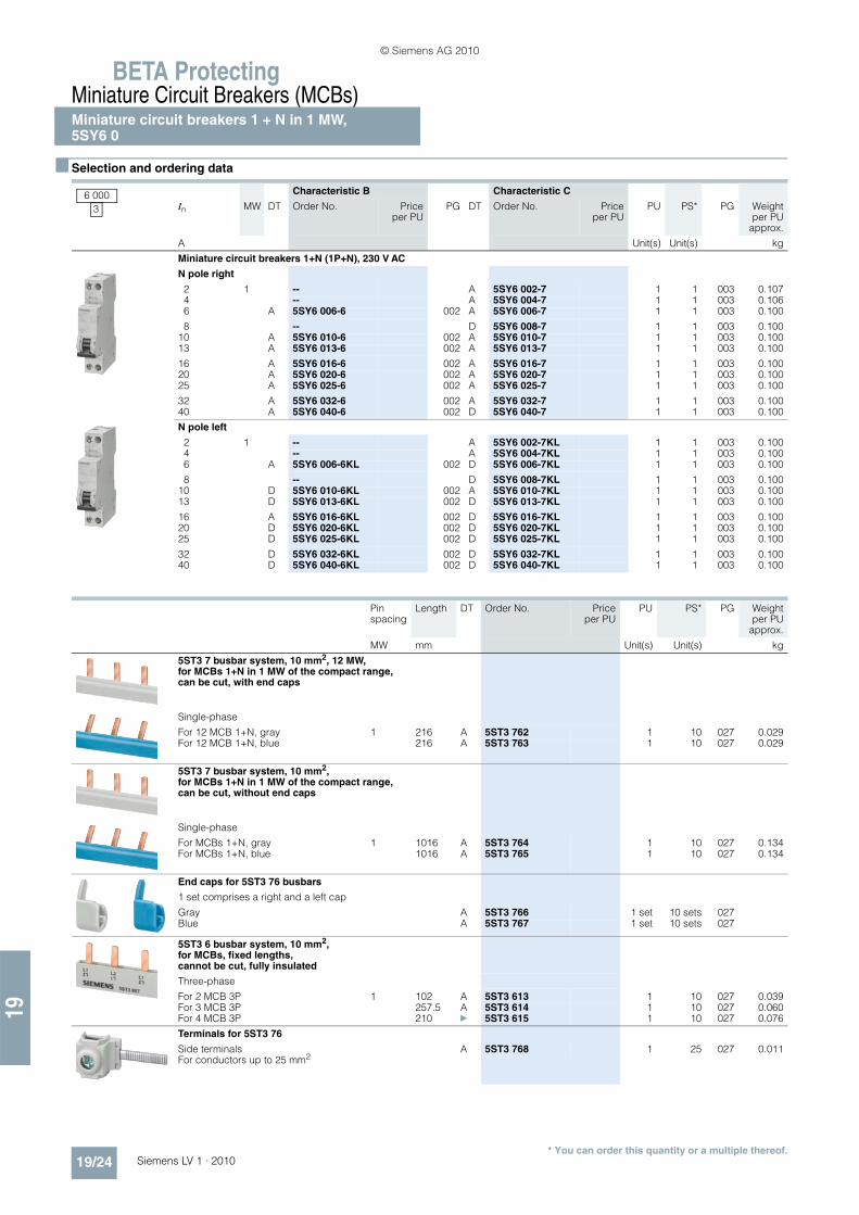
Miniature circuit breakers 1 + N in 1 MW,5SY6 0
19/23Siemens LV 1 · 2010
■ Overview
These miniature circuit breakers are used for the protection of plants with switched neutral conductors in distribution boards with little space. They are only a single modular width.
Compact busbars facilitate installation in space saving distribu-tion boards.
The devices are approved for worldwide use according to IEC standards for systems up to 250 V AC. 60 V DC per pole is per-mitted in DC systems according to IEC standards.
■ Benefits
• Auxiliary switches and fault signal contacts from the high-capacity range can be freely mounted on these miniature circuit breakers. This increases availability and cuts down on logistics.
• By actuating the latching slide, the miniature circuit breakers can be quickly and easily removed from the assembly.
• For 3-pole busbars, the 5ST3 6 busbar system is used – a uni-versal system, suitable for all miniature circuit breakers.
• The infeed can be implemented either from the top or the bottom. Additional terminals with lateral insertion of conduc-tors facilitate mounting when using large conductor cross-sections.
© Siemens AG 2010
BETA ProtectingMiniature Circuit Breakers (MCBs)Miniature circuit breakers 1 + N in 1 MW,5SY6 0
19/24 Siemens LV 1 · 2010
19
* You can order this quantity or a multiple thereof.
■ Selection and ordering data
Characteristic B Characteristic C
In MW DT Order No. Priceper PU
PG DT Order No. Priceper PU
PU PS* PG Weightper PU
approx.
A Unit(s) Unit(s) kg
Miniature circuit breakers 1+N (1P+N), 230 V AC
N pole right
2 1 -- A 5SY6 002-7 1 1 003 0.1074 -- A 5SY6 004-7 1 1 003 0.1066 A 5SY6 006-6 002 A 5SY6 006-7 1 1 003 0.100
8 -- D 5SY6 008-7 1 1 003 0.10010 A 5SY6 010-6 002 A 5SY6 010-7 1 1 003 0.10013 A 5SY6 013-6 002 A 5SY6 013-7 1 1 003 0.100
16 A 5SY6 016-6 002 A 5SY6 016-7 1 1 003 0.10020 A 5SY6 020-6 002 A 5SY6 020-7 1 1 003 0.10025 A 5SY6 025-6 002 A 5SY6 025-7 1 1 003 0.100
32 A 5SY6 032-6 002 A 5SY6 032-7 1 1 003 0.10040 A 5SY6 040-6 002 D 5SY6 040-7 1 1 003 0.100
N pole left
2 1 -- A 5SY6 002-7KL 1 1 003 0.1004 -- A 5SY6 004-7KL 1 1 003 0.1006 A 5SY6 006-6KL 002 D 5SY6 006-7KL 1 1 003 0.100
8 -- D 5SY6 008-7KL 1 1 003 0.10010 D 5SY6 010-6KL 002 A 5SY6 010-7KL 1 1 003 0.10013 D 5SY6 013-6KL 002 D 5SY6 013-7KL 1 1 003 0.100
16 A 5SY6 016-6KL 002 D 5SY6 016-7KL 1 1 003 0.10020 D 5SY6 020-6KL 002 D 5SY6 020-7KL 1 1 003 0.10025 D 5SY6 025-6KL 002 D 5SY6 025-7KL 1 1 003 0.100
32 D 5SY6 032-6KL 002 D 5SY6 032-7KL 1 1 003 0.10040 D 5SY6 040-6KL 002 D 5SY6 040-7KL 1 1 003 0.100
6 0003
Pin spacing
Length DT Order No. Priceper PU
PU PS* PG Weightper PU
approx.
MW mm Unit(s) Unit(s) kg
5ST3 7 busbar system, 10 mm2, 12 MW, for MCBs 1+N in 1 MW of the compact range, can be cut, with end caps
Single-phase
For 12 MCB 1+N, gray 1 216 A 5ST3 762 1 10 027 0.029For 12 MCB 1+N, blue 216 A 5ST3 763 1 10 027 0.029
5ST3 7 busbar system, 10 mm2, for MCBs 1+N in 1 MW of the compact range, can be cut, without end caps
Single-phase
For MCBs 1+N, gray 1 1016 A 5ST3 764 1 10 027 0.134For MCBs 1+N, blue 1016 A 5ST3 765 1 10 027 0.134
End caps for 5ST3 76 busbars
1 set comprises a right and a left cap
Gray A 5ST3 766 1 set 10 sets 027Blue A 5ST3 767 1 set 10 sets 027
5ST3 6 busbar system, 10 mm2, for MCBs, fixed lengths, cannot be cut, fully insulated
Three-phase
For 2 MCB 3P 1 102 A 5ST3 613 1 10 027 0.039For 3 MCB 3P 257.5 A 5ST3 614 1 10 027 0.060For 4 MCB 3P 210 } 5ST3 615 1 10 027 0.076
Terminals for 5ST3 76
Side terminals A 5ST3 768 1 25 027 0.011For conductors up to 25 mm2
© Siemens AG 2010

19
BETA ProtectingMiniature Circuit Breakers (MCBs)
Additional components
19/25Siemens LV 1 · 2010
■ Overview
This mounting concept enables all additional 5ST3 components to be combined with Siemens miniature circuit breakers as well as with 5SU1 RCBOs.
Auxiliary contacts
The auxiliary switch (AS) signals the contact position of the min-iature circuit breaker regardless of whether the miniature circuit breaker was tripped by hand or by a fault. An additional version for the switching of small currents and small voltages for the con-trol of programmable control systems (PLCs) according to EN 61131-2 is available. The version "auxiliary switch with test button" enables the testing of auxiliary contacts without the need to switch the miniature circuit breaker.
The fault signal contact (FC) signals the automatic tripping of the miniature circuit breaker in the event of a fault, e. g. due to an overload or a short circuit. The contact position does not change when the miniature circuit breaker is tripped by hand.
Test and reset button
The version "fault signal contact with test and reset button" en-ables the testing of auxiliary contacts without the need to switch the miniature circuit breaker. With this version, if the miniature cir-cuit breaker is automatically tripped in the event of a fault, this also automatically trips the RESET button integrated in the han-dle of the fault signal contact. After the miniature circuit breaker has been tripped, the reset button can be manually acknowl-edged, which deletes the pending fault signal.
Auxiliary releases
Undervoltage releases are integrated e. g. in an EMERGENCY-STOP loop, thus ensuring that the miniature circuit breaker trips in the event of an emergency, which in turn ensures disconnec-tion of the control circuit according to EN 60204. In the event that the voltage is interrupted or too low, it also trips, i. e. prevents the miniature circuit breaker from switching on.
Shunt trips are used for the remote tripping of miniature circuit breakers. Remote-controlled mechanisms are used for the re-mote switching (ON/OFF) of miniature circuit breakers and the remote switching (ON) of RC units.
Remote control
Remote-controlled mechanisms also enable local manual switching. A blocking function permits maintenance work. In the event that a miniature circuit breaker or RC unit is tripped, an ac-knowledgment must be carried out prior to switching back on. The remote-controlled mechanism has an operating mode se-lector switch with the functions: "Locked", "Manual" and "Remote Switching". The mechanism can be mechanically latched and locked, which serves to protect personnel during maintenance work.
RC units
RC units are combined with miniature circuit breakers of A, B, C and D characteristics. They then form a combination of RCCB and MCB for personnel, fire and line protection. The combina-tions can be individually assembled to suit the requirement. For information on RC units, please refer to the section "Residual current protective devices".
■ Benefits
• Universal mountability of all additional components
• The 5SY and 5SP miniature circuit breakers are ideal for the quick and easy mounting of auxiliary switches and fault signal contacts. Captive metal brackets on additional components ensure the quick and easy mounting of devices on the miniature circuit breakers without the need for tools.
• The auxiliary switches with test button enable easy testing of the control circuits by hand during operation of the complete system without the need to switch the miniature circuit breaker.
• Fault signal contacts with test and reset button enable the sim-ple testing of auxiliary circuits and, in the event of a fault, ac-knowledgement of the fault over the reset button, without the need to switch the miniature circuit breakers.
• Auxiliary switches for small outputs enable their use with PLCs.
• Bus systems, such as instabus KNX, AS-Interface bus or PROFIBUS, are integrated in the communication over binary inputs and actuators.
Auxiliary switches (AS)• Huge range of applications, thanks to additional versions for
the switching of small currents and voltages for the control of programmable control systems (PLCs) according to EN 61131-2.
Remote-controlled mechanisms (RC)• The remote-controlled mechanism has an operating mode se-
lector switch with the functions: "Locked", "Manual" and "Re-mote switching". The mechanism can be mechanically latched and locked, which serves to protect personnel during maintenance work.
© Siemens AG 2010

BETA ProtectingMiniature Circuit Breakers (MCBs)
Additional components
19/26 Siemens LV 1 · 2010
19
* You can order this quantity or a multiple thereof.
■ Selection and ordering data
MW DT Order No. Priceper PU
PU PS* PG Weightper PU
approx.
Unit(s) Unit(s) kg
Auxiliary switches (AS)
For 5SY, 5SP miniature circuit breakers, 5SU1 RCBOs and 5TE8 switches
1 NO + 1 NC 0.5 } 5ST3 010 1 1 027 0.050• for low loading } 5ST3 013 1 1 027 0.050
2 NO A 5ST3 011 1 1 027 0.050• for low loading B 5ST3 014 1 1 027 0.050
2 NC A 5ST3 012 1 1 027 0.050• for low loading B 5ST3 015 1 1 027 0.050
Auxiliary switches (AS) with test button
For 5SY, 5SP miniature circuit breakers, 5SU1 RCBOs and 5TE8 switches
1 NO + 1 NC 0.5 A 5ST3 010-2 1 1 027 0.045• for low loading A 5ST3 013-2 1 1 027 0.045
2 NO A 5ST3 011-2 1 1 027 0.045• for low loading A 5ST3 014-2 1 1 027 0.045
2 NC A 5ST3 012-2 1 1 027 0.045• for low loading A 5ST3 015-2 1 1 027 0.045
Fault signal contacts (FC)
For 5SY, 5SP miniature circuit breakers and 5SU1 RCBOs
1 NO + 1 NC 0.5 } 5ST3 020 1 1 027 0.0502 NO B 5ST3 021 1 1 027 0.0502 NC A 5ST3 022 1 1 027 0.050
Fault signal contacts (FC) with test and acknowledgement button
For 5SY, 5SP miniature circuit breakers and 5SU1 RCBOs
1 NO + 1 NC 0.5 A 5ST3 020-2 1 1 027 0.0502 NO A 5ST3 021-2 1 1 027 0.0502 NC A 5ST3 022-2 1 1 027 0.050
Undervoltage releases (UR)
For 5SY, 5SP miniature circuit breakers and 5SU1 RCBOs but not for 5SY6 0..
With integrated auxiliary switch
230 AC 1 A 5ST3 040 1 1 027 0.115110 DC B 5ST3 041 1 1 027 0.11524 DC B 5ST3 042 1 1 027 0.115
Without integrated auxiliary switch
230 AC 1 A 5ST3 043 1 1 027 0.115110 DC B 5ST3 044 1 1 027 0.11524 DC A 5ST3 045 1 1 027 0.115
Shunt trips (ST)
For 5SY, 5SP miniature circuit breakers and 5SU1 RCBOs but not for 5SY6 0..
2 NO 1 } 5ST3 030 1 1 027 0.0982 NC 1 } 5ST3 031 1 1 027 0.098
Remote-controlled mechanisms (RC)
For 5SY, 5SP4 miniature circuit breakers and 5SU1 RCBOs
230 AC 3.5 A 5ST3 050 1 1 027 0.395
Handle couplers for additional components
For mounting the additional components: auxiliary switches, fault signal contacts, shunt trips and undervoltage releases onto 5SU1 RCBOs, you require a handle coupler (1 set = 5 units).
} 5ST3 805-1 1 set 1 set 027 0.008
© Siemens AG 2010

19
BETA ProtectingMiniature Circuit Breakers (MCBs)
Additional components
19/27Siemens LV 1 · 2010* You can order this quantity or a multiple thereof.
Rated residual current
Rated current MW DT Order No. Priceper PU
PU PS* PG Weightper PU
approx.
I�n InmA A Unit(s) Unit(s) kg
RC units, type A, instantaneous tripping
For 5SY miniature circuit breakersbut not for 5SY5 and 5SY6 0..
2P, 230 ... 400 V AC, 50 ... 60 Hz
10 0.3 ... 16 2 B 5SM2 121-6 1 1 007 0.18030 0.3 ... 40 } 5SM2 322-6 1 1 007 0.170300 A 5SM2 622-6 1 1 007 0.170
30 0.3 ... 63 A 5SM2 325-6 1 1 007 0.170100 B 5SM2 425-6 1 1 007 0.170300 B 5SM2 625-6 1 1 007 0.170500 B 5SM2 725-6 1 1 007 0.170
3P, 230 ... 400 V AC, 50 ... 60 Hz
30 0.3 ... 40 3 A 5SM2 332-6 1 1 007 0.260300 A 5SM2 632-6 1 1 007 0.260
30 0.3 ... 63 B 5SM2 335-6 1 1 007 0.260100 B 5SM2 435-6 1 1 007 0.260300 B 5SM2 635-6 1 1 007 0.260500 B 5SM2 735-6 1 1 007 0.260
4P, 230 ... 400 V AC, 50 ... 60 Hz
30 0.3 ... 40 3 } 5SM2 342-6 1 1 007 0.290300 } 5SM2 642-6 1 1 007 0.290
30 0.3 ... 63 A 5SM2 345-6 1 1 007 0.290100 B 5SM2 445-6 1 1 007 0.290300 A 5SM2 645-6 1 1 007 0.290500 A 5SM2 745-6 1 1 007 0.290
for 5SP4 miniature circuit breakers
2P, 125 ... 230 V AC, 50 ... 60 Hz
30 80 ... 100 3.5 B 5SM2 327-6 1 1 007 0.410300 B 5SM2 627-6 1 1 007 0.410
4P, 230 ... 400 V AC, 50 ... 60 Hz
30 80 ... 100 5 B 5SM2 347-6 1 1 007 0.630300 A 5SM2 647-6 1 1 007 0.630
© Siemens AG 2010

BETA ProtectingMiniature Circuit Breakers (MCBs)
Additional components
19/28 Siemens LV 1 · 2010
19
* You can order this quantity or a multiple thereof.
RC units, type A, super resistantæ
For 5SY miniature circuit breakersbut not for 5SY5 and 5SY6 0..
2P, 230 ... 400 V AC, 50 ... 60 Hz
30 0.3 ... 40 2 B 5SM2 322-6KK01 1 1 007 0.350
30 0.3 ... 63 B 5SM2 325-6KK01 1 1 007 0.350
3P, 230 ... 400 V AC, 50 ... 60 Hz
30 0.3 ... 40 3 B 5SM2 332-6KK01 1 1 007 0.365
30 0.3 ... 63 B 5SM2 335-6KK01 1 1 007 0.365
4P, 230 ... 400 V AC, 50 ... 60 Hz
30 0.3 ... 40 3 B 5SM2 342-6KK01 1 1 007 0.290
30 0.3 ... 63 B 5SM2 345-6KK01 1 1 007 0.290
RC units, type A, selective î
For 5SY miniature circuit breakersbut not for 5SY5 and 5SY6 0..
2P, 230 ... 400 V AC, 50 ... 60 Hz
300 0.3 ... 40 2 A 5SM2 622-8 1 1 007 0.170
300 0.3 ... 63 B 5SM2 625-8 1 1 007 0.170
3P, 230 ... 400 V AC, 50 ... 60 Hz
300 0.3 ... 63 3 B 5SM2 635-8 1 1 007 0.260500 B 5SM2 735-8 1 1 007 0.4001000 B 5SM2 835-8 1 1 007 0.260
4P, 230 ... 400 V AC, 50 ... 60 Hz
300 0.3 ... 63 3 A 5SM2 645-8 1 1 007 0.290500 A 5SM2 745-8 1 1 007 0.4001000 A 5SM2 845-8 1 1 007 0.290
for 5SP4 miniature circuit breakers
2P; 125 ... 230 V AC, 50 ... 60 Hz
300 80 ... 100 3.5 B 5SM2 627-8 1 1 007 0.410
4P; 230 ... 400 V AC, 50 ... 60 Hz
300 80 ... 100 5 A 5SM2 647-8 1 1 007 0.6301000 A 5SM2 847-8 1 1 007 0.630
Rated residual current
Rated current MW DT Order No. Priceper PU
PU PS* PG Weightper PU
approx.
I�n InmA A Unit(s) Unit(s) kg
© Siemens AG 2010

19
BETA ProtectingMiniature Circuit Breakers (MCBs)
Additional components
19/29Siemens LV 1 · 2010* You can order this quantity or a multiple thereof.
Version MW DT Order No. Priceper PU
PU PS* PG Weightper PU
approx.
Unit(s) Unit(s) kg
Terminal covers
For miniature circuit breakers for additional cov-ering of the screw openings per pole, sealable. On 5SY prevents the device also being removed from the standard mounting rail.
B 5ST3 800 1 10 027 0.001
Handle locking devices
Prevents inadvertent manual on and off switch-ing, sealable
For 5SP and 5SY miniature circuit breakers For padlock with max. 3 mm shackle
A 5ST3 801 1 1 027 0.008
For 5SJ, 5SP and 5SY miniature circuit breakers For padlock with max. 3 ... 6 mm shackle
A 5ST3 806 1 5 027 0.007
Padlocks
For 5ST3 801 and 5ST3 806 handle locking device } 5ST3 802 1 1 027 0.027
Locking devices
Consisting of 5ST3 801 handle locking device and 5ST3 802 padlock
B 5ST3 803 1 set 1 set 027 0.035
Spacers
Can be placed on either side of the standard mounting rail, so that two spacers allow for con-venient cable routing
0.5 } 5TG8 240 1 2 027 0.010
Fixing parts
Made of plastic, for use with a mounting plate
B 5ST2 201 1 1 027 0.012
Inscription labels
15 mm × 9 mm, 3 frames à 44 labels, can be mounted on casing collar, white, self-adhesive
B 5ST2 173 1 set 1 set 027 0.038
Labeling systems
Inscriptions on self-adhesive labels for a neat and uniform appearance in the power distribution system. The labeling program can be downloaded to your PC free of charge:
www.siemens.com/labeling-tool
Recommended ELAT-3-747 labels for printing out on standard printers can be ordered at BRADY:
www.bradycorp.com
© Siemens AG 2010

BETA ProtectingMiniature Circuit Breakers (MCBs)
Additional components
19/30 Siemens LV 1 · 2010
19
* You can order this quantity or a multiple thereof.
■ More information
More information about additional components for miniature cir-cuit breakers can be found in Catalog ET B1 · 2010. The current issue of the catalog can be downloaded from www.siemens.com/e-installation-catalogs.
Version DT Order No. Priceper PU
PU PS* PG Weightper PU
approx.
Unit(s) Unit(s) kg
Terminal covers, gray
For surface mounting, degree of protection IP40, sealable, with TH 35 standard mounting rail
• Up to 2.5 MW B 5SW3 004 1 1 008 0.084• Up to 4.5 MW B 5SW3 005 1 1 008 0.114
Wall enclosures, gray
For flush mounting, degree of protection IP40, with TH 35 standard mounting rail
• Up to 2.5 MW B 5SW3 006 1 1/4 008 0.126• Up to 4.5 MW B 5SW3 007 1 1 008 0.147
Molded-plastic enclosures, gray
For surface mounting, degree of protection IP54, sealable, with transparent hinged lid, with TH 35 standard mounting rail
For 4.5 MW A 5SW1 200 1 1 008 0.450
Covers
Can be assembled as mini distribution board, suitable for all devices, cover parts prepared for rail mounting of conventional label caps, comprising:
• End plates (can be snapped onto TH 35 standard mounting rail)
A 5ST2 134 1 10 027 0.022
• Angle section (approx. 1 m long) A 5ST2 135 1 5 027 0.330
• Alternatively flat profile (as a cover between the rows of devices length approx. 1 m)
B 5ST2 136 1 5 027 0.260
Holder for installation in front panels
Universal application for devices from 1 MW to 6 MW
Cutout dimensions:Height 45+0.5 mm Width 23, 41, 59, 77, 95 or 113 mm B 7LF9 006 1 1 025 0.071
8GB4 563
Intermediate frame for 70 mm devices in N distribution boards
Versions
• 1 row A 8GB4 561 1 1 032 0.900
• 2 rows A 8GB4 562 1 1 032 1.100
• 3 rows A 8GB4 563 1 1 032 1.300
• 4 rows A 8GB4 564 1 1 032 1.500
More information about ALPHA distribution boards, ALPHA SIMBOX small distribution boards and intermediate frames can be found in the Catalog ET A1, Chapter ALPHA SIMBOX Small Distribution Boards.
© Siemens AG 2010

19
BETA ProtectingMiniature Circuit Breakers (MCBs)
BusbarsStandard 5ST3 6, 5ST3 7
19/31Siemens LV 1 · 2010
■ Overview
The busbar system with pin-type connections can be used for all 5SJ6 . . .-.KS and 5SY miniature circuit breakers with or without mounted auxiliary switch (AS) or fault signal contact (FC).
Busbars in 10 mm2 and 16 mm2 versions are available.
The 5ST3 7 busbar system with busbars that can be cut to any length required.
The extremely flexible 5ST3 6 busbar system with fixed lengths also enables installation in any length as the busbars can be overlapped. No further need for time-consuming tasks, such as cutting, cutting to length, deburring, cleaning of cut surfaces and mounting of end caps.
Any free pins on the busbars can be made finger-safe by cover-ing with touch protection.
For further information on bus-mounting miniature circuit break-ers with residual current operated circuit breakers, please refer to the chapter"Residual current protective devices".
■ Benefits
• Between the devices, the busbar, located at the bottom and behind the conductor, provides an optimum wiring space with easy view of the inserted conductor. This enables easy control of connections.
• The ability to overlap the busbar mounting enables a cross-section enlargement of up to 32 mm2 using the respective components, 10 and 16 mm2.
• Combinations of any number of units are possible by overlap-ping the fixed-length busbars.
• The fact that the connection of the conductor is always clearly visible facilitates control and insertion of conductors of all pole types and considerably reduces mounting times.
© Siemens AG 2010

BETA ProtectingMiniature Circuit Breakers (MCBs)BusbarsStandard 5ST3 6, 5ST3 7
19/32 Siemens LV 1 · 2010
19
* You can order this quantity or a multiple thereof.
■ Selection and ordering data
Pin spacing
Length DT Order No. Priceper PU
PU PS* PG Weightper PU
approx.
MW mm Unit(s) Unit(s) kg
5ST3 6 busbar system, 10 mm2, for miniature circuit breakers Fixed lengths, cannot be cut, fully insulated
Single-phase
For 2 MCB 1P 1 33 A 5ST3 600 1 10 027 0.005For 6 MCB 1P 105 A 5ST3 601 1 10 027 0.018For 12 MCB 1P 210 A 5ST3 602 1 10 027 0.036
Single-phaseFor MCB with AS or FC
For 2 MCB 1P 1.5 40 A 5ST3 603 1 10 027 0.008For 6 MCB 1P 156,5 A 5ST3 604 1 10 027 0.024For 9 MCB 1P 237 A 5ST3 605 1 10 027 0.036
Two-phase
For 2 MCB 2P 1 75,5 A 5ST3 606 1 10 027 0.016For 3 MCB 2P 105 A 5ST3 607 1 10 027 0.024For 6 MCB 2P 210 A 5ST3 608 1 10 027 0.048
Three-phase
For 2 MCB 3P 1 102 A 5ST3 613 1 10 027 0.039For 3 MCB 3P 157,5 A 5ST3 614 1 10 027 0.060For 4 MCB 3P 210 } 5ST3 615 1 10 027 0.076
Three-phase For MCB with AS or FC
For 2 MCB 3P 1+1+1.5 115 A 5ST3 616 1 10 027 0.040For 4 MCB 3P 237 A 5ST3 617 1 10 027 0.080
For 6 MCB 1P 1.5 125 A 5ST3 618 1 10 027 0.044For 9 MCB 1P 229 A 5ST3 620 1 10 027 0.066
4-phase
For 2 MCB 4P or 3P+N 1 145 A 5ST3 621 1 10 027 0.051For 3 MCB 4P or 3P+N 215 A 5ST3 622 1 10 027 0.078For 6 MCB 2P or 1P+N 215 A 5ST3 623 1 10 027 0.078
Three-phase
For 1 RC unit 4P N rightand 8 MCB 1P 1 210 A 5ST3 624 1 10 027 0.075
For 1 RC unit 4P N leftand 8 MCB 1P 1 192 A 5ST3 667 1 10 027 0.061
5ST3 6 busbars, 16 mm2, for miniature circuit breakersFixed lengths, cannot be cut, fully insulated
Single-phase
For 2 MCB 1P 1 33 A 5ST3 630 1 10 027 0.008For 6 MCB 1P 105 A 5ST3 631 1 10 027 0.025For 12 MCB 1P 210 A 5ST3 632 1 10 027 0.048
Single-phase For MCB with AS or FC
For 2 MCB 1P 1.5 40 A 5ST3 633 1 10 027 0.013For 6 MCB 1P 156,5 A 5ST3 634 1 10 027 0.039For 9 MCB 1P 237 A 5ST3 635 1 10 027 0.059
Two-phase
For 2 MCB 2P 1 75.5 A 5ST3 636 1 10 027 0.024For 3 MCB 2P 105 A 5ST3 637 1 10 027 0.039For 6 MCB 2P 210 A 5ST3 638 1 10 027 0.076
Two-phase For MCB with AS or FC
For 2 MCB 2P 1 + 1.5 75.5 A 5ST3 640 1 10 027 0.026For 3 MCB 2P 120,5 A 5ST3 641 1 10 027 0.045For 5 MCB 2P 210 A 5ST3 642 1 10 027 0.084
© Siemens AG 2010

19
BETA ProtectingMiniature Circuit Breakers (MCBs)
BusbarsStandard 5ST3 6, 5ST3 7
19/33Siemens LV 1 · 2010* You can order this quantity or a multiple thereof.
5ST3 6 busbars, 16 mm2,for miniature circuit breakers Fixed lengths, cannot be cut, fully insulated
Three-phase
For 2 MCB 3P 1 102,5 A 5ST3 643 1 10 027 0.058For 3 MCB 3P 157,5 A 5ST3 644 1 10 027 0.083For 4 MCB 3P 210 } 5ST3 645 1 10 027 0.110
Three-phaseFor MCB with AS or FC
For 2 MCB 3P 1+1+1.5 115 A 5ST3 646 1 10 027 0.060For 4 MCB 3P 237 A 5ST3 647 1 10 027 0.120
For 6 MCB 1P 1.5 156 A 5ST3 648 1 10 027 0.061For 9 MCB 1P 245 A 5ST3 650 1 10 027 0.093
5ST3 6 busbars, 16 mm2, for miniature circuit breakers Fixed lengths, cannot be cut, fully insulated
4-phase
For 2 MCB 4P or 3P+N 1 A 5ST3 651 1 10 027 0.080For 3 MCB 4P or 3P+N A 5ST3 652 1 10 027 0.116For 6 MCB 2P or 1P+N A 5ST3 653 1 10 027 0.116
Three-phase
For 1 RC unit 4P N rightand 8 MBC 1P 1 210 A 5ST3 654 1 10 027 0.114
For 1 RC unit 4P N leftand 8 MCB 1P 1 210 A 5ST3 668 1 10 027 0.099
Touch protection for free terminals
Yellow, RAL 1004 5 x 1 pin
A 5ST3 655 1 10 027 0.003
Assortments
10 mm2
20 × 5ST3 613 + 10 × 5ST3 614 + 50 × 5ST3 615 + 50 × 5ST3 655
A 5ST3 656 1 set 1 set 027 5.490
16 mm2
20 × 5ST3 643 + 10 × 5ST3 644 + 50 × 5ST3 645 + 50 × 5ST3 655
A 5ST3 657 1 set 1 set 027 7.640
5ST3 7 busbar system, 10 mm2, 12 MW For miniature circuit breakers Can be cut, with end caps
Single-phase, angled
For 12 MCB 1P 1 214 A 5ST3 730 1 1 027 0.040For 9 MCB 1P with AS or FC 1.5 A 5ST3 732 1 1 027 0.040
Two-phase
For 6 MCB 2P 1 A 5ST3 734 1 1 027 0.060For 4 MCB 2P with AS or FC 1+1.5 A 5ST3 736 1 1 027 0.060
Three-phase
For 4 MCB 3P 1 } 5ST3 738 1 1 027 0.100For 3 MCB 3P with AS or FC 1+1+1.5 A 5ST3 741 1 1 027 0.100For 3 MCB 1P with AS or FC 1.5 A 5ST3 743 1 1 027 0.100
4-phase
For 3 MCB 4P or 3P+N 1 A 5ST3 745 1 1 027 0.150
5ST3 7 busbar system, 10 mm m2, 56 MW For miniature circuit breakers Can be cut, without end caps
Single-phase, angled
For MCB 1P 1 1016 A 5ST3 731 1 1 027 0.190For MCB 1P with AS or FC 1.5 A 5ST3 733 1 1 027 0.190
Two-phase
For MCB 2P 1 A 5ST3 735 1 1 027 0.290For MCB 2P with AS or FC 1+1.5 A 5ST3 737 1 1 027 0.290
Three-phase
For MCB 3P 1 A 5ST3 740 1 1 027 0.430For MCB 3P with AS or FC 1+1+1.5 A 5ST3 742 1 1 027 0.430For MCB 1P with AS or FC 1.5 A 5ST3 744 1 1 027 0.430
4-phase
For MCB 4P or 3P+N 1 A 5ST3 746 1 1 027 0.700
Pin spacing
Length DT Order No. Priceper PU
PU PS* PG Weightper PU
approx.
MW mm Unit(s) Unit(s) kg
© Siemens AG 2010

BETA ProtectingMiniature Circuit Breakers (MCBs)BusbarsStandard 5ST3 6, 5ST3 7
19/34 Siemens LV 1 · 2010
19
* You can order this quantity or a multiple thereof.
5ST3 7 busbar system, 16 mm2, 12 MW For miniature circuit breakers Can be cut, without end caps
Single-phase, angled
For MCB 1P 1 214 } 5ST3 700 1 1 027 0.040For MCB 1P with AS or FC 1.5 A 5ST3 702 1 1 027 0.040
Two-phase
For MCB 2P 1 A 5ST3 704 1 1 027 0.060For MCB 2P with AS or FC 1+1.5 A 5ST3 706 1 1 027 0.060
Three-phase
For MCB 3P 1 } 5ST3 708 1 1 027 0.100For MCB 3P with AS or FC 1+1+1.5 A 5ST3 711 1 1 027 0.100For MCB 1P with AS or FC 1.5 A 5ST3 713 1 1 027 0.100
4-phase
For MCB 4P or 3P+N 1 A 5ST3 715 1 1 027 0.150
5ST3 7 busbar system, 16 mm2, 56 MW For miniature circuit breakers Can be cut, without end caps
Single-phase, angled
For MCB 1P 1 1016 A 5ST3 701 1 1 027 0.190For MCB 1P with AS or FC 1.5 A 5ST3 703 1 1 027 0.190
Two-phase
For MCB 2P 1 A 5ST3 705 1 1 027 0.290For MCB 2P with AS or FC 1+1.5 A 5ST3 707 1 1 027 0.290
Three-phase
For MCB 3P 1 } 5ST3 710 1 1 027 0.430For MCB 3P with AS or FC 1+1+1.5 A 5ST3 712 1 1 027 0.430For MCB 1P with AS or FC 1.5 A 5ST3 714 1 1 027 0.430
4-phase
For MCB 4P or 3P+N 1 A 5ST3 716 1 1 027 0.700
End caps for 5ST3 7, can be cut
For single-phase busbars } 5ST3 748 1 10 027 0.001For two- and three-phase busbars } 5ST3 750 1 10 027 0.001For 4-phase busbars } 5ST3 718 1 10 027 0.001
5ST3 7 busbar system, 10 mm2, 12 MW For MCBs 1+N in 1 MW of the compact range, can be cut, with end caps
Single-phase
For 12 MCB 1+N, gray 216 A 5ST3 762 1 10 027 0.029For 12 MCB 1+N, blue A 5ST3 763 1 10 027 0.029
5ST3 7 busbar system, 10 mm2, 56 MW For MCBs 1+N in 1 MW of the compact range, can be cut, without end caps
Single-phase
For MCBs 1+N, gray 1016 A 5ST3 764 1 10 027 0.134For MCBs 1+N, blue A 5ST3 765 1 10 027 0.134
End caps for 5ST3 76
1 set comprises a right and a left cap
Gray A 5ST3 766 1 set 10 sets 027Blue A 5ST3 767 1 set 10 sets 027
Terminals for 5ST3 76
Terminal version SFor conductors up to 25 mm2 A 5ST3 768 1 25 027 0.011
Pin spacing
Length DT Order No. Priceper PU
PU PS* PG Weightper PU
approx.
MW mm Unit(s) Unit(s) kg
© Siemens AG 2010

19
BETA ProtectingMiniature Circuit Breakers (MCBs)
Busbarsaccording to UL 508, 5ST3 7 . . . - . HG
19/35Siemens LV 1 · 2010
■ Overview
Products according to UL standards are used in North America, but also in several other countries. In particular when exporting machines or electrical switchgear and equipment to the USA, acceptance and delivery are possible only if the relevant UL standards are satisfied.
The 5ST3 7. . .-.HG busbar system according to UL 508 and CSA is suitable for universal use worldwide with all 5SY and 5SP miniature circuit breakers for Supplementary Protection certified according to UL 1077 as well as for 3NW and 3NC fuse holders certified according to UL 512.
The busbars are available in single-, two- and three-phase ver-sion with different pin spacings and with two cross-sections 18 mm² and 25 mm². Infeed can be directly into the terminals of the miniature circuit breaker or through connection terminals. The connection terminals are available in two versions – for di-rect infeed at the busbar or for infeed directly at the miniature cir-cuit breaker/fuse holder. Pins that are not required can be cov-ered with touch protection covers.
■ Benefits
• Bus mounting with infeed through a connection terminal di-rectly on the miniature circuit breaker up to a conductor cross-section of 35 mm².
• Bus mounting with infeed at the fuse holder for conductor cross-sections up to 35 mm²
• Infeed directly on the miniature circuit breaker up to a cross-section of 35 mm² and connection terminal for connection di-rectly on the busbar up to a conductor cross-section of 50 mm².
• Suitable for universal use according to both IEC and UL stan-dards
• Can be used for 5SY, 5SP miniature circuit breakers and for Class CC, cylindrical and SITOR fuse holders
• UL-tested combination – device and busbar• Different cross-sections 18 mm² and 25 mm²
© Siemens AG 2010

BETA ProtectingMiniature Circuit Breakers (MCBs)Busbarsaccording to UL 508, 5ST3 7 . . . - . HG
19/36 Siemens LV 1 · 2010
19
* You can order this quantity or a multiple thereof.
■ Selection and ordering data
Pin spacing
Length
DT Order No. Priceper PU
PU PS* PG Weightper PU
approx.
MW mm Unit(s) Unit(s) kg
5ST3 7. .-.HG busbars according to UL 508, 18 mm2, can be cut, without end caps
Single-phase
• For MCB 1P (5SY) or fuse holder 10 x 38 Class CC (3NC1 091, 3NW7 513-0HG)
1 1000 A 5ST3 701-0HG 1 10 012 0.330
• For MCB 1P (5SY, 5SP) with AS or FC or fuse holder 14 x 51 (3NC1 491, 3NW7 111)
1.5 1000 A 5ST3 703-0HG 1 10 012 0.330
Two-phase
• For MCB 2P (5SY) or fuse holder 10 x 38/Class CC (3NC1 092, 3NW7 523-0HG)
1 1000 A 5ST3 705-0HG 1 10 012 0.508
• For MCB 2P (5SY) with AS or FC 1+1.5 1000 A 5ST3 707-0HG 1 10 012 0.508
Three-phase
• For MCB 3P (5SY) or fuse holder 10 x 38/Class CC (3NC1 093, 3NW7 533-0HG)
1 1000 A 5ST3 710-0HG 1 10 012 0.800
• For MCB 3P (5SY) with AS or FC 1+1+1.5 1000 A 5ST3 712-0HG 1 10 012 0.800
• For MCB 1P (5SY, 5SP) with AS or FC or fuse holder 14 x 51 (3NC1 493, 3NW7 131)
1.5 1000 A 5ST3 714-0HG 1 10 012 0.820
5ST3 7. .-.HG busbars according to UL 508, 25 mm2, can be cut, without end caps
Single-phase
• For MCB 1P (5SP) or fuse holder 14 x 51 (3NC1 491, 3NW7 111)
1.5 1000 A 5ST3 701-2HG 1 10 012 0.450
Two-phase
• For MCB 2P (5SP) or fuse holder 14 x 51 (3NC1 492, 3NW7 121)
1.5 1000 A 5ST3 705-2HG 1 10 012 0.690
Three-phase
• For MCB 3P (5SP) or fuse holder 14 x 51 (3NC1 493, 3NW7 131)
1.5 1000 A 5ST3 710-2HG 1 10 012 1.090
End caps for 5ST3 7. .-.HG
• For single-phase busbars A 5ST3 748-0HG 1 10 012 0.001
• For two- and three-phase busbars A 5ST3 750-0HG 1 10 012 0.001
Connection terminals according to UL 508
Infeed to device
• 35 mm2 A 5ST3 770-0HG 1 10 012 0.035
Infeed to busbar
• 50 mm2 A 5ST3 770-1HG 1 10 012 0.016
Touch protection covers for busbars acc. to UL 508
• 5 x 1 pin A 5ST3 655-0HG 1 10 012 0.003
© Siemens AG 2010

19
BETA ProtectingMiniature Circuit Breakers (MCBs)
BusbarsUniversal, 5ST3 5
19/37Siemens LV 1 · 2010
■ Overview
Busbars serve the safe and fast connection of modular installa-tion devices, such as miniature circuit breakers, residual current operated circuit breakers and switching and control devices.
With the universal busbar system, different devices - with and without additional components and in various versions - can be
quickly and easily connected with each other by means of a few components for numerous possible applications. For example, residual current operated circuit breakers 3+N can be combined with miniature circuit breakers 1+N in a single modular width for cost-effective splitting of the phases.
■ Benefits
• The universal busbar system can be used for all modular in-stallation devices such as 5SY, 5SX, 5SM, 5SU
• A safe bus-mounting system can be quickly assembled with few components
• Two-phase insulating parts with plug-on mount for implement-ing two-phase or multi-phase bus mounting
• Universal multi-phase bus mounting of 3 phases + N with 2 x two-phase insulating parts with plug-on mount for combina-tion of different modular installation devices with additional components
• Individual connection of devices using standardized connec-tion pins, with plug-in design for easy and comfortable con-necting
• Free choice of phase sequence
• Single-phase insulating parts with plug-on mount for imple-menting single-phase or multi-phase bus mounting
• Single-phase bus mounting with one single-phase insulating part with plug-on mount for combination of RCCB and MCB
© Siemens AG 2010

BETA ProtectingMiniature Circuit Breakers (MCBs)BusbarsUniversal, 5ST3 5
19/38 Siemens LV 1 · 2010
19
* You can order this quantity or a multiple thereof.
■ Selection and ordering data
Length DT Order No. Priceper PU
PU PS* PG Weightper PU
approx.
mm Unit(s) Unit(s) kg
Universal busbar system, 16 mm2, 1000 mm, can be cut, without end caps
Single-phase 1000 A 5ST3 500-0 1 12 027 0.433
Insulating parts with plug-on mount
Two-phase 1000 A 5ST3 501-0 1 12 027 0.823
Insulating parts with plug-on mount
Connection pins, terminal spacing 1 MW for RCCBs or MCBs
Connection pin 6/12 12 A 5ST3 510-0 1 50 027 0.007
For L/N
Connection pin 6/21 21 A 5ST3 511-0 1 50 027 0.008
For L/N
Connection pins, terminal spacing 0.5 MW for MCBs 1 + N in a single modular width
Connection pin 4/23 23 A 5ST3 512-0 1 50 027 0.006
For L 1
Connection pin 4/3 3 A 5ST3 513-0 1 50 027 0.005
For L 2
Connection pin 4/9 9 A 5ST3 514-0 1 50 027 0.005
For L 3
Connection pin 4/21 21 A 5ST3 515-0 1 50 027 0.005
For N
AccessoriesTouch protection profiles 1000 A 5ST3 507-0 1 12 027 0.003
End caps A 5ST3 508-0 1 12 027 0.020
1 unit for 3 phases + N or can be divided into 1 x 2-phase or 2 x 1-phase insulating part
© Siemens AG 2010

19
BETA ProtectingMiniature Circuit Breakers (MCBs)
Miniature circuit breakersaccording to UL 489 and IEC, 5SJ4 . . . - . HG
19/39Siemens LV 1 · 2010
■ Overview
UL standards are applied in North America and a number of other countries. This is of particular importance to European ex-porters of electrical switchgear equipment for machines who ex-port to the USA, as their products will only be accepted if they meet the relevant UL standards.
Countless devices from the Siemens low-voltage circuit protec-tion range comply with UL standards and are therefore suitable for implementation worldwide in both IEC/EN and UL applica-tions within the framework of their specified use.
Miniature circuit breakers certified to UL 489 permit use as an all-round solution for protection tasks in distribution boards, con-trol cabinets and control systems to UL 508A as "branch protec-tors". In particular, they are also approved for the protection of electrical circuits in heating, ventilation and air conditioning sys-tems (HVAC), as well as for DC applications up to 60 V/125 V.
This covers a wide range of protection tasks, in residential and non-residential buildings, as well as in industry. The tripping characteristics B, C and D to EN/IEC 60898 have been adapted so that they fall in the permissible tripping range to UL 489, as well as for applications at 25 °C and 40 °C.
This means that the devices are approved for use according to both standards. The enclosure dimensions of the devices corre-spond to DIN format. This means that the device series are suit-able for universal use worldwide to IEC or UL standards.
The key difference between the three device series is their appli-cation in different power supply systems.• 5SJ4 …-.HG40: 240/120 V AC, 1-pole, "same polarity only",• 5SJ4 …-.HG41: 240 V AC, 1, 2 and 3-pole,• 5SJ4 …-.HG42: 480Y/277 V AC, 1, 2 and 3-pole.
The terminals are suitable for "field wiring". This means that the devices can be installed not only in factory-finished distribution boards and control cabinets, but also on-site in a customer sys-tem.
All additional components such as auxiliary switches (AS), fault signal contacts (FC) and shunt trips (ST) are mountable on the miniature circuit breakers according to UL 489 and IEC 5SJ4 …-.HG. Captive metal brackets on the additional compo-nents ensure fast and reliable mounting on the miniature circuit breakers.
Single-, two- and three-phase busbars in 3 lengths with 6, 12 or 18 pins are available as accessories for all device series. The in-feed is over connection terminals, which are available in two ver-sions, for direct infeed at either the busbar or the miniature cir-cuit breakers. Pins that are not required can be covered with touch protection covers.
■ Benefits
• Can be used globally for all applications in residential, non-residential and industrial buildings. This facilitates the plan-ning of plants and enhances export opportunities
• The devices can be used according to IEC/EN 60898 and UL 489, Which means these devices can be installed any-where in the world.
• Miniature circuit breakers with 480Y/277 V to 40 A, with 240/120 V and 240 V to 63 A
• Can be used with both alternating voltage and direct voltage up to 125 V
• Rated switching capacity up to 14 kA according to UL 489 and up to 15 kA according to IEC 60947-2
• Quick mounting with busbars up to 115 A and feeder termi-nals up to 50 mm2.
• Infeed direct at miniature circuit breaker for conductor cross-sections up to 35 mm2
• Busbar mounting with central infeed directly on the busbar up to conductor cross-section of 50 mm2
• Accessories: Auxiliary switches, fault signal contacts and shunt trips up to 480 V can be easily mounted on these minia-ture circuit breakers.
© Siemens AG 2010

BETA ProtectingMiniature Circuit Breakers (MCBs)Miniature circuit breakersaccording to UL 489 and IEC, 5SJ4 . . . - . HG
19/40 Siemens LV 1 · 2010
19
* You can order this quantity or a multiple thereof.
■ Selection and ordering data
1) 1 MW (modular width) = 18 mm.
1) 1 MW (modular width) = 18 mm.
Characteristic B
In Width DT Order No. Priceper PU
PU PS* PG Weightper PU
approx.
A MW1) Unit(s) Unit(s) kg
MCBs "same polarity only" 1P, 240 V AC
6 1 B 5SJ4 106-6HG40 1 1 012 0.12010 B 5SJ4 110-6HG40 1 1 012 0.12013 C 5SJ4 113-6HG40 1 1 012 0.120
15 C 5SJ4 118-6HG40 1 1 012 0.12016 C 5SJ4 116-6HG40 1 1 012 0.12020 C 5SJ4 120-6HG40 1 1 012 0.120
25 C 5SJ4 125-6HG40 1 1 012 0.12030 C 5SJ4 130-6HG40 1 1 012 0.12032 C 5SJ4 132-6HG40 1 1 012 0.120
35 C 5SJ4 135-6HG40 1 1 012 0.12040 C 5SJ4 140-6HG40 1 1 012 0.12045 C 5SJ4 145-6HG40 1 1 012 0.120
50 C 5SJ4 150-6HG40 1 1 012 0.12060 C 5SJ4 160-6HG40 1 1 012 0.12063 C 5SJ4 163-6HG40 1 1 012 0.120
Characteristic C Characteristic D
In Width DT Order No. Priceper PU
PG DT Order No. Priceper PU
PU PS* PG Weightper PU
approx.
A MW1) Unit(s) Unit(s) kg
MCBs "same polarity only" 1P, 240 V AC0.3 1 C 5SJ4 114-7HG40 012 C 5SJ4 114-8HG40 1 1 012 0.1200.5 C 5SJ4 105-7HG40 012 C 5SJ4 105-8HG40 1 1 012 0.1201 B 5SJ4 101-7HG40 012 C 5SJ4 101-8HG40 1 1 012 0.120
1.6 C 5SJ4 115-7HG40 012 C 5SJ4 115-8HG40 1 1 012 0.1202 B 5SJ4 102-7HG40 012 C 5SJ4 102-8HG40 1 1 012 0.1203 B 5SJ4 103-7HG40 012 C 5SJ4 103-8HG40 1 1 012 0.120
4 B 5SJ4 104-7HG40 012 C 5SJ4 104-8HG40 1 1 012 0.1205 C 5SJ4 111-7HG40 012 C 5SJ4 111-8HG40 1 1 012 0.1206 B 5SJ4 106-7HG40 012 C 5SJ4 106-8HG40 1 1 012 0.120
8 B 5SJ4 108-7HG40 012 C 5SJ4 108-8HG40 1 1 012 0.12010 B 5SJ4 110-7HG40 012 C 5SJ4 110-8HG40 1 1 012 0.12013 C 5SJ4 113-7HG40 012 C 5SJ4 113-8HG40 1 1 012 0.120
15 C 5SJ4 118-7HG40 012 C 5SJ4 118-8HG40 1 1 012 0.12016 B 5SJ4 116-7HG40 012 C 5SJ4 116-8HG40 1 1 012 0.12020 B 5SJ4 120-7HG40 012 C 5SJ4 120-8HG40 1 1 012 0.120
25 B 5SJ4 125-7HG40 012 C 5SJ4 125-8HG40 1 1 012 0.12030 C 5SJ4 130-7HG40 012 C 5SJ4 130-8HG40 1 1 012 0.12032 C 5SJ4 132-7HG40 012 C 5SJ4 132-8HG40 1 1 012 0.120
35 C 5SJ4 135-7HG40 012 C 5SJ4 135-8HG40 1 1 012 0.12040 C 5SJ4 140-7HG40 012 C 5SJ4 140-8HG40 1 1 012 0.12045 C 5SJ4 145-7HG40 012 C 5SJ4 145-8HG40 1 1 012 0.120
50 C 5SJ4 150-7HG40 012 C 5SJ4 150-8HG40 1 1 012 0.12060 C 5SJ4 160-7HG40 012 C 5SJ4 160-8HG40 1 1 012 0.12063 C 5SJ4 163-7HG40 012 C 5SJ4 163-8HG40 1 1 012 0.120
© Siemens AG 2010

19
BETA ProtectingMiniature Circuit Breakers (MCBs)
Miniature circuit breakersaccording to UL 489 and IEC, 5SJ4 . . . - . HG
19/41Siemens LV 1 · 2010* You can order this quantity or a multiple thereof.
1) 1 MW (modular width) = 18 mm.
Characteristic C Characteristic D
In Width DT Order No. Priceper PU
PG DT Order No. Priceper PU
PU PS* PG Weightper PU
approx.
A MW1) Unit(s) Unit(s) kg
MCBs 1P, 240 V AC
0.3 1 C 5SJ4 114-7HG41 012 C 5SJ4 114-8HG41 1 1 012 0.1550.5 C 5SJ4 105-7HG41 012 C 5SJ4 105-8HG41 1 1 012 0.1551 C 5SJ4 101-7HG41 012 C 5SJ4 101-8HG41 1 1 012 0.155
1.6 C 5SJ4 115-7HG41 012 C 5SJ4 115-8HG41 1 1 012 0.1552 C 5SJ4 102-7HG41 012 C 5SJ4 102-8HG41 1 1 012 0.1553 C 5SJ4 103-7HG41 012 C 5SJ4 103-8HG41 1 1 012 0.155
4 C 5SJ4 104-7HG41 012 C 5SJ4 104-8HG41 1 1 012 0.1555 C 5SJ4 111-7HG41 012 C 5SJ4 111-8HG41 1 1 012 0.1556 C 5SJ4 106-7HG41 012 C 5SJ4 106-8HG41 1 1 012 0.155
8 C 5SJ4 108-7HG41 012 C 5SJ4 108-8HG41 1 1 012 0.15510 C 5SJ4 110-7HG41 012 C 5SJ4 110-8HG41 1 1 012 0.15513 C 5SJ4 113-7HG41 012 C 5SJ4 113-8HG41 1 1 012 0.155
15 C 5SJ4 118-7HG41 012 C 5SJ4 118-8HG41 1 1 012 0.15516 C 5SJ4 116-7HG41 012 C 5SJ4 116-8HG41 1 1 012 0.15520 C 5SJ4 120-7HG41 012 C 5SJ4 120-8HG41 1 1 012 0.155
25 C 5SJ4 125-7HG41 012 C 5SJ4 125-8HG41 1 1 012 0.15530 C 5SJ4 130-7HG41 012 C 5SJ4 130-8HG41 1 1 012 0.15532 C 5SJ4 132-7HG41 012 C 5SJ4 132-8HG41 1 1 012 0.155
35 C 5SJ4 135-7HG41 012 C 5SJ4 135-8HG41 1 1 012 0.15540 C 5SJ4 140-7HG41 012 C 5SJ4 140-8HG41 1 1 012 0.15545 C 5SJ4 145-7HG41 012 C 5SJ4 145-8HG41 1 1 012 0.155
50 C 5SJ4 150-7HG41 012 C 5SJ4 150-8HG41 1 1 012 0.15560 C 5SJ4 160-7HG41 012 C 5SJ4 160-8HG41 1 1 012 0.15563 C 5SJ4 163-7HG41 012 C 5SJ4 163-8HG41 1 1 012 0.155
MCBs 2P, 240 V AC
0.3 2 C 5SJ4 214-7HG41 012 C 5SJ4 214-8HG41 1 1 012 0.3100.5 C 5SJ4 205-7HG41 012 C 5SJ4 205-8HG41 1 1 012 0.3101 C 5SJ4 201-7HG41 012 C 5SJ4 201-8HG41 1 1 012 0.310
1.6 C 5SJ4 215-7HG41 012 C 5SJ4 215-8HG41 1 1 012 0.3102 C 5SJ4 202-7HG41 012 C 5SJ4 202-8HG41 1 1 012 0.3103 C 5SJ4 203-7HG41 012 C 5SJ4 203-8HG41 1 1 012 0.310
4 C 5SJ4 204-7HG41 012 C 5SJ4 204-8HG41 1 1 012 0.3105 C 5SJ4 211-7HG41 012 C 5SJ4 211-8HG41 1 1 012 0.3106 C 5SJ4 206-7HG41 012 C 5SJ4 206-8HG41 1 1 012 0.310
8 C 5SJ4 208-7HG41 012 C 5SJ4 208-8HG41 1 1 012 0.31010 C 5SJ4 210-7HG41 012 C 5SJ4 210-8HG41 1 1 012 0.31013 C 5SJ4 213-7HG41 012 C 5SJ4 213-8HG41 1 1 012 0.310
15 C 5SJ4 218-7HG41 012 C 5SJ4 218-8HG41 1 1 012 0.31016 C 5SJ4 216-7HG41 012 C 5SJ4 216-8HG41 1 1 012 0.31020 C 5SJ4 220-7HG41 012 C 5SJ4 220-8HG41 1 1 012 0.310
25 C 5SJ4 225-7HG41 012 C 5SJ4 225-8HG41 1 1 012 0.31030 C 5SJ4 230-7HG41 012 C 5SJ4 230-8HG41 1 1 012 0.31032 C 5SJ4 232-7HG41 012 C 5SJ4 232-8HG41 1 1 012 0.310
35 C 5SJ4 235-7HG41 012 C 5SJ4 235-8HG41 1 1 012 0.31040 C 5SJ4 240-7HG41 012 C 5SJ4 240-8HG41 1 1 012 0.31045 C 5SJ4 245-7HG41 012 C 5SJ4 245-8HG41 1 1 012 0.310
50 C 5SJ4 250-7HG41 012 C 5SJ4 250-8HG41 1 1 012 0.31060 C 5SJ4 260-7HG41 012 C 5SJ4 260-8HG41 1 1 012 0.31063 C 5SJ4 263-7HG41 012 C 5SJ4 263-8HG41 1 1 012 0.310
© Siemens AG 2010

BETA ProtectingMiniature Circuit Breakers (MCBs)Miniature circuit breakersaccording to UL 489 and IEC, 5SJ4 . . . - . HG
19/42 Siemens LV 1 · 2010
19
* You can order this quantity or a multiple thereof.
1) 1 MW (modular width) = 18 mm.
Characteristic C Characteristic D
In Width DT Order No. Priceper PU
PG DT Order No. Priceper PU
PU PS* PG Weightper PU
approx.
A MW1) Unit(s) Unit(s) kg
MCBs 3P, 240 V AC
0.3 3 C 5SJ4 314-7HG41 012 C 5SJ4 314-8HG41 1 1 012 0.4650.5 C 5SJ4 305-7HG41 012 C 5SJ4 305-8HG41 1 1 012 0.4651 C 5SJ4 301-7HG41 012 C 5SJ4 301-8HG41 1 1 012 0.465
1.6 C 5SJ4 315-7HG41 012 C 5SJ4 315-8HG41 1 1 012 0.4652 C 5SJ4 302-7HG41 012 C 5SJ4 302-8HG41 1 1 012 0.4653 C 5SJ4 303-7HG41 012 C 5SJ4 303-8HG41 1 1 012 0.465
4 C 5SJ4 304-7HG41 012 C 5SJ4 304-8HG41 1 1 012 0.4655 C 5SJ4 311-7HG41 012 C 5SJ4 311-8HG41 1 1 012 0.4656 C 5SJ4 306-7HG41 012 C 5SJ4 306-8HG41 1 1 012 0.465
8 C 5SJ4 308-7HG41 012 C 5SJ4 308-8HG41 1 1 012 0.46510 C 5SJ4 310-7HG41 012 C 5SJ4 310-8HG41 1 1 012 0.46513 C 5SJ4 313-7HG41 012 C 5SJ4 313-8HG41 1 1 012 0.465
15 C 5SJ4 318-7HG41 012 C 5SJ4 318-8HG41 1 1 012 0.46516 C 5SJ4 316-7HG41 012 C 5SJ4 316-8HG41 1 1 012 0.46520 C 5SJ4 320-7HG41 012 C 5SJ4 320-8HG41 1 1 012 0.465
25 C 5SJ4 325-7HG41 012 C 5SJ4 325-8HG41 1 1 012 0.46530 C 5SJ4 330-7HG41 012 C 5SJ4 330-8HG41 1 1 012 0.46532 C 5SJ4 332-7HG41 012 C 5SJ4 332-8HG41 1 1 012 0.465
35 C 5SJ4 335-7HG41 012 C 5SJ4 335-8HG41 1 1 012 0.46540 C 5SJ4 340-7HG41 012 C 5SJ4 340-8HG41 1 1 012 0.46545 C 5SJ4 345-7HG41 012 C 5SJ4 345-8HG41 1 1 012 0.465
50 C 5SJ4 350-7HG41 012 C 5SJ4 350-8HG41 1 1 012 0.46560 C 5SJ4 360-7HG41 012 C 5SJ4 360-8HG41 1 1 012 0.46563 C 5SJ4 363-7HG41 012 C 5SJ4 363-8HG41 1 1 012 0.465
MCBs 1P, 480Y/277 V AC
0.3 1 C 5SJ4 114-7HG42 012 C 5SJ4 114-8HG42 1 1 012 0.1550.5 C 5SJ4 105-7HG42 012 C 5SJ4 105-8HG42 1 1 012 0.1551 C 5SJ4 101-7HG42 012 C 5SJ4 101-8HG42 1 1 012 0.155
1.6 C 5SJ4 115-7HG42 012 C 5SJ4 115-8HG42 1 1 012 0.1552 C 5SJ4 102-7HG42 012 C 5SJ4 102-8HG42 1 1 012 0.1553 C 5SJ4 103-7HG42 012 C 5SJ4 103-8HG42 1 1 012 0.155
4 C 5SJ4 104-7HG42 012 C 5SJ4 104-8HG42 1 1 012 0.1555 C 5SJ4 111-7HG42 012 C 5SJ4 111-8HG42 1 1 012 0.1556 C 5SJ4 106-7HG42 012 C 5SJ4 106-8HG42 1 1 012 0.155
8 C 5SJ4 108-7HG42 012 C 5SJ4 108-8HG42 1 1 012 0.15510 C 5SJ4 110-7HG42 012 C 5SJ4 110-8HG42 1 1 012 0.15513 C 5SJ4 113-7HG42 012 C 5SJ4 113-8HG42 1 1 012 0.155
15 C 5SJ4 118-7HG42 012 C 5SJ4 118-8HG42 1 1 012 0.15516 C 5SJ4 116-7HG42 012 C 5SJ4 116-8HG42 1 1 012 0.15520 C 5SJ4 120-7HG42 012 C 5SJ4 120-8HG42 1 1 012 0.155
25 C 5SJ4 125-7HG42 012 C 5SJ4 125-8HG42 1 1 012 0.15530 C 5SJ4 130-7HG42 012 C 5SJ4 130-8HG42 1 1 012 0.15532 C 5SJ4 132-7HG42 012 C 5SJ4 132-8HG42 1 1 012 0.155
35 C 5SJ4 135-7HG42 012 -- 1 1 0.15540 C 5SJ4 140-7HG42 012 -- 1 1 0.155
© Siemens AG 2010

19
BETA ProtectingMiniature Circuit Breakers (MCBs)
Miniature circuit breakersaccording to UL 489 and IEC, 5SJ4 . . . - . HG
19/43Siemens LV 1 · 2010* You can order this quantity or a multiple thereof.
1) 1 MW (modular width) = 18 mm.
Characteristic C Characteristic D
In Width DT Order No. Priceper PU
PG DT Order No. Priceper PU
PU PS* PG Weightper PU
approx.
A MW1) Unit(s) Unit(s) kg
MCBs 2P, 480Y/277 V AC
0.3 2 C 5SJ4 214-7HG42 012 C 5SJ4 214-8HG42 1 1 012 0.3100.5 C 5SJ4 205-7HG42 012 C 5SJ4 205-8HG42 1 1 012 0.3101 C 5SJ4 201-7HG42 012 C 5SJ4 201-8HG42 1 1 012 0.310
1.6 C 5SJ4 215-7HG42 012 C 5SJ4 215-8HG42 1 1 012 0.3102 C 5SJ4 202-7HG42 012 C 5SJ4 202-8HG42 1 1 012 0.3103 C 5SJ4 203-7HG42 012 C 5SJ4 203-8HG42 1 1 012 0.310
4 C 5SJ4 204-7HG42 012 C 5SJ4 204-8HG42 1 1 012 0.3105 C 5SJ4 211-7HG42 012 C 5SJ4 211-8HG42 1 1 012 0.3106 C 5SJ4 206-7HG42 012 C 5SJ4 206-8HG42 1 1 012 0.310
8 C 5SJ4 208-7HG42 012 C 5SJ4 208-8HG42 1 1 012 0.31010 C 5SJ4 210-7HG42 012 C 5SJ4 210-8HG42 1 1 012 0.31013 C 5SJ4 213-7HG42 012 C 5SJ4 213-8HG42 1 1 012 0.310
15 C 5SJ4 218-7HG42 012 C 5SJ4 218-8HG42 1 1 012 0.31016 C 5SJ4 216-7HG42 012 C 5SJ4 216-8HG42 1 1 012 0.31020 C 5SJ4 220-7HG42 012 C 5SJ4 220-8HG42 1 1 012 0.310
25 C 5SJ4 225-7HG42 012 C 5SJ4 225-8HG42 1 1 012 0.31030 C 5SJ4 230-7HG42 012 C 5SJ4 230-8HG42 1 1 012 0.31032 C 5SJ4 232-7HG42 012 C 5SJ4 232-8HG42 1 1 012 0.310
35 C 5SJ4 235-7HG42 012 -- 1 1 0.31040 C 5SJ4 240-7HG42 012 -- 1 1 0.310
MCBs 3P, 480Y/277 V AC
0.3 3 C 5SJ4 314-7HG42 012 C 5SJ4 314-8HG42 1 1 012 0.4650.5 C 5SJ4 305-7HG42 012 C 5SJ4 305-8HG42 1 1 012 0.4651 C 5SJ4 301-7HG42 012 C 5SJ4 301-8HG42 1 1 012 0.465
1.6 C 5SJ4 315-7HG42 012 C 5SJ4 315-8HG42 1 1 012 0.4652 C 5SJ4 302-7HG42 012 C 5SJ4 302-8HG42 1 1 012 0.4653 C 5SJ4 303-7HG42 012 C 5SJ4 303-8HG42 1 1 012 0.465
4 C 5SJ4 304-7HG42 012 C 5SJ4 304-8HG42 1 1 012 0.4655 C 5SJ4 311-7HG42 012 C 5SJ4 311-8HG42 1 1 012 0.4656 C 5SJ4 306-7HG42 012 C 5SJ4 306-8HG42 1 1 012 0.465
8 C 5SJ4 308-7HG42 012 C 5SJ4 308-8HG42 1 1 012 0.46510 C 5SJ4 310-7HG42 012 C 5SJ4 310-8HG42 1 1 012 0.46513 C 5SJ4 313-7HG42 012 C 5SJ4 313-8HG42 1 1 012 0.465
15 C 5SJ4 318-7HG42 012 C 5SJ4 318-8HG42 1 1 012 0.46516 C 5SJ4 316-7HG42 012 C 5SJ4 316-8HG42 1 1 012 0.46520 C 5SJ4 320-7HG42 012 C 5SJ4 320-8HG42 1 1 012 0.465
25 C 5SJ4 325-7HG42 012 C 5SJ4 325-8HG42 1 1 012 0.46530 C 5SJ4 330-7HG42 012 C 5SJ4 330-8HG42 1 1 012 0.46532 C 5SJ4 332-7HG42 012 C 5SJ4 332-8HG42 1 1 012 0.465
35 C 5SJ4 335-7HG42 012 -- 1 1 0.46540 C 5SJ4 340-7HG42 012 -- 1 1 0.465
© Siemens AG 2010

BETA ProtectingMiniature Circuit Breakers (MCBs)Miniature circuit breakersaccording to UL 489 and IEC, 5SJ4 . . . - . HG
19/44 Siemens LV 1 · 2010
19
* You can order this quantity or a multiple thereof.
■ Accessories
1) 1 MW (modular width) = 18 mm.
1) 1 MW (modular width) = 18 mm.2) Any free pins on the busbars must be covered with the 5ST3 666-1HG
touch protection cover.
Width DT Order No. Priceper PU
PU PS* PG Weightper PU
approx.
MW1) Unit(s) Unit(s) kg
Auxiliary switches (AS) according to UL 489
1 NO + 1 NC 0.5 C 5ST3 010-0HG 1 1 012 0.071
2 NO C 5ST3 011-0HG 1 1 012 0.050
2 NC C 5ST3 012-0HG 1 1 012 0.050
Fault signal contacts (FC) according to UL 489
1 NO + 1 NC 0.5 C 5ST3 020-0HG 1 1 012 0.050
2 NO C 5ST3 021-0HG 1 1 012 0.050
2 NC C 5ST3 022-0HG 1 1 012 0.050
Shunt trips (ST) according to UL 489
110 ... 480 V AC 1 } 5ST3 030-0HG 1 1 012 0.098
24 ... 60 V AC/DC } 5ST3 031-0HG 1 1 012 0.098
Pin spacing Length DT Order No. Priceper PU
PU PS* PG Weightper PU
approx.
MW1) mm Unit(s) Unit(s) kg
Busbars acc. to UL 489 specially for 5SJ4 … -.HG.. MCBs fixed lengths, cannot be cut2)
Single-phaseFor 6 MCB 1P 1 100 A 5ST3 663-0HG 1 10 012 0.056For 12 MCB 1P 205 A 5ST3 663-1HG 1 10 012 0.112For 18 MCB 1P 310 A 5ST3 663-2HG 1 10 012 0.170
Two-phaseFor 3 MCB 2P 1 100 A 5ST3 664-0HG 1 10 012 0.065For 6 MCB 2P 205 A 5ST3 664-1HG 1 10 012 0.137For 9 MCB 2P 310 A 5ST3 664-2HG 1 10 012 0.211
Three-phaseFor 2 MCB 3P 1 100 A 5ST3 665-0HG 1 10 012 0.067For 4 MCB 3P 205 A 5ST3 665-1HG 1 10 012 0.155For 6 MCB 3P 310 A 5ST3 665-2HG 1 10 012 0.243
Terminals acc. to UL 489 specially for 5SJ4 … -.HG..MCBs
Infeed on the MCBmax. 35 mm2 A 5ST3 666-0HG 1 10 012 0.033
Infeed on the busbarmax. 50 mm2 A 5ST3 666-2HG 1 10 012 0.034
© Siemens AG 2010

19
BETA ProtectingMiniature Circuit Breakers (MCBs)
Miniature circuit breakers acc. to UL 489 and IECCircuit breaker terminals, 5SK9
19/45Siemens LV 1 · 2010* You can order this quantity or a multiple thereof.
Miniature circuit breakers according to UL 489 and IEC, 5SJ4 . . .-.HG
1) 1 MW (modular width) = 18 mm.
■ Overview
Circuit breaker terminals, 5SK9
Circuit breaker terminals are used for short-circuit protection or for protection against overloading and short-circuiting in auxil-iary and control circuits after control transformers. All terminals are designed for 2 wires. The terminal block labeling accesso-ries are used for inscription.
■ Benefits
• Integration of line protection switching function in the terminal technology of control cabinets in compact 12 mm design
• Display of switching position or the "Tripped" state for the fast detection of faults
• Switching/isolating function facilitates fault locating• Device versions with integral auxiliary switch (AS) signal the
contact position• Device versions with floating through-type connection parallel
to the switching contacts facilitate line connection.
These devices are listed as "Supplementary Protectors" acc. to UL 1077 (UL Recognized Components) and CSA 235 (CSA Component Accepted).
Pin spacing Length DT Order No. Priceper PU
PU PS* PG Weightper PU
approx.
MW1) mm Unit(s) Unit(s) kg
Touch protection covers for busbars acc. to UL 489
3 × 1 pin A 5ST3 666-1HG 1 10 012 0.003
Handle locking devices A 5ST3 801 1 1 027 0.008
Can be sealed against unwanted manual ON/OFF switch-ing, padlock with max. 3 mm shackle
Padlocks } 5ST3 802 1 1 027 0.027
For 5ST3 801 handle locking device
© Siemens AG 2010

BETA ProtectingMiniature Circuit Breakers (MCBs)
Circuit breaker terminals, 5SK9
19/46 Siemens LV 1 · 2010
19
* You can order this quantity or a multiple thereof.
■ Selection and ordering data
Version In DT Order No. Priceper PU
PU PS* PG Weightper PU
approx.
A Unit(s) Unit(s) kg
Terminal size 1.5 mm2
With short-circuit release1 A 5SK9 011-1KK24 1 10 027 0.0532 A 5SK9 011-1KK25 1 10 027 0.0524 B 5SK9 011-1KK26 1 10 027 0.053
6 A 5SK9 011-1KK27 1 10 027 0.05310 B 5SK9 011-1KK28 1 10 027 0.050
With overload and short-circuit release1 A 5SK9 011-2KK24 1 10 027 0.0532 A 5SK9 011-2KK25 1 10 027 0.0524 A 5SK9 011-2KK26 1 10 027 0.053
6 A 5SK9 011-2KK27 1 10 027 0.05310 B 5SK9 011-2KK28 1 10 027 0.050
Terminal size 2.5 mm2
With short-circuit release, auxiliary switch with 1 NO and 1 NC
1 B 5SK9 011-6KK24 1 5 027 0.0962 B 5SK9 011-6KK25 1 5 027 0.0934 B 5SK9 011-6KK26 1 5 027 0.092
6 B 5SK9 011-6KK27 1 5 027 0.09310 B 5SK9 011-6KK28 1 5 027 0.090
With overload and short-circuit release, auxiliary switch with 1 NC and through-type connection
1 B 5SK9 011-4KK24 1 5 027 0.0892 A 5SK9 011-4KK25 1 5 027 0.0924 A 5SK9 011-4KK26 1 5 027 0.091
6 B 5SK9 011-4KK27 1 5 027 0.10510 B 5SK9 011-4KK28 1 5 027 0.088
With overload and short-circuit release, auxiliary switch with 1 NO and 1 NC
0.5 B 5SK9 011-8KK23 1 5 027 0.0921 A 5SK9 011-8KK24 1 5 027 0.0922 A 5SK9 011-8KK25 1 5 027 0.097
4 A 5SK9 011-8KK26 1 5 027 0.0926 A 5SK9 011-8KK27 1 5 027 0.09010 B 5SK9 011-8KK28 1 5 027 0.090
Feeder terminals Rated uninterrupted current 76 AConnection up to 16 mm²
A 5ST1 822-7KK00 1 10 027 0.012
5ST1 822-7KK02
Link rails, single-phase Rated uninterrupted current 65 A
A 5ST1 822-7KK02 1 20 027 0.015
5 connecting pins• Length 104 mm• For terminals: 5SK9 011-4KK2.,
5SK9 011-6KK2., 5SK9 011-8KK2.
9 connecting pins• Length 104 mm• For terminals: 5SK9 011-1KK2.,
5SK9 011-2KK2.
A 5ST1 822-7KK07 1 20 027 0.013
10 connecting pins• Length 206 mm• For terminals: 5SK9 011-4KK2.,
5SK9 011-6KK2.
A 5ST1 822-7KK01 1 20 027 0.031
5ST1 822-7KK06
18 connecting pins• Length 206 mm• For terminals: 5SK9 011-1KK2.,
5SK9 011-2KK2.
A 5ST1 822-7KK06 1 20 027 0.036
5ST1 822-7KK04
Link rails, two-phase Rated uninterrupted current 120 AFor terminal: 5SK9 011-4KK2.
5 connecting pins/pole• Length 104 mm
A 5ST1 822-7KK04 1 10 027 0.031
9 connecting pins/pole• Length 206 mm
A 5ST1 822-7KK03 1 10 027 0.061
© Siemens AG 2010

19
BETA ProtectingResidual Current Protective Devices
RCCBs, type A, 5SM3
19/47Siemens LV 1 · 2010
■ Overview
RCCBs of type A are used in all systems up to 240/415 V AC. They trip in the event of both sinusoidal AC residual currents and pulsating DC residual currents.
RCCBs with a rated residual current of maximum 30 mA are used for personnel, material and fire protection, as well as for ad-ditional protection against direct contact. RCCBs with a rated re-sidual current of 10 mA are primarily used in areas that represent an increased risk for personnel.
Since the amendment of DIN VDE 0100-410 came into effect in June 2007, all socket outlet current circuits up to 20 A must now also be fitted with residual current protective devices with a rated residual current of max. 30 mA. This also applies to out-door electrical circuits up to 32 A for the connection of portable equipment.
Devices with a rated residual current of maximum 300 mA are used as preventative fire protection in case of insulation faults. RCCBs with a rated residual current of 100 mA are primarily used outside Europe.
Note:DIN VDE 0100 is the German version of IEC 60364.
SIGRES
SIGRES RCCBs were developed for use in harsh ambient con-ditions, such as swimming baths as protection against chlorine and ozone, in the agricultural sector (ammonia), on building sites and in the chemical industry (nitrogen oxide, sulfur dioxide, solvents), in the food processing industry (hydrogen sulfide) and in unheated rooms (dampness). The patented active condensa-tion protection requires a permanent power supply and the in-feed from below with the RCCBs switched off.
For use under ambient conditions according to the product stan-dard (EN 61008-1), the actuation interval for pressing the test button can be extended to once a year.
Super resistantæ
Super resistant (short-time delayed) RCCBs comply with the maximum permissible break times for instantaneous devices. However, by implementing a short-time delay they prevent un-necessary trippings, and thus plant faults, when pulse-shaped leakage currents occur - as is the case when capacitors are switched on.
Selectiveî
Can be used as upstream group switch for selective tripping contrary to a downstream, instantaneous or super resistant RCCB.
■ Benefits
• Instantaneous RCCBs with the N-connection on the left-hand side enable simple bus mounting with standard pin busbars with MCBs installed on the right-hand side
• Instantaneous RCCBs with the N connection on the right-hand side can be bus-mounted with MCBs using a special pin bus-bar
• Instantaneous devices have a surge current withstand capa-bility with current waveform 8/20 �s of more than 1 kA, super resistant of more than 3 kA and selective of more than 5 kA. This ensures safe operation
• SIGRES has an extremely long service life due to patented ac-tive condensation protection and the same dimensions for fast and simple exchange of already installed instantaneous RC-CBs
• Super resistant devices increase plant availability, as unnec-essary tripping is prevented in systems with short-time voltage peaks
• Selective RCCBs increase plant availability, as in the event of a fault, a staggered tripping time enables the selective trip-ping of RCCBs connected in series
• Auxiliary switches or remote controlled mechanisms are also available as additional components
• The operating handle and the test button can be locked by means of a handle locking device.
Selection aid for determining a suitable residual current protective device
RCCB RCBO
SIGRES 500 V 50- 400 Hz
RC unit
K S
AB+B
AC
3+N1+N 42
B C D
3
I2_15509a
Design Selection criterion
Type Equipment Circuit, load current,
residual current
System, equipment,ambient conditions
Equipment
Version
Number of poles
Additionalprotection
I∆n ≤ 30 mA
Fire protection
I∆n ≤ 300 mA
Trip conditions limited I∆n
Installationregulation
VDE 0100-410
Rated residual current I∆nprotection objective
-530-7xx-482
EquipmentRated current In
Trip conditions acc. to VDE 0100-410
Equipment
Only with RCBOs withMCB characteristic
VDS 3501
residual current protection I∆n > 30mA
© Siemens AG 2010

BETA ProtectingResidual Current Protective Devices
RCCBs, type A, 5SM3
19/48 Siemens LV 1 · 2010
19
* You can order this quantity or a multiple thereof.
■ Selection and ordering data
Rated residual current
Rated current Max. permissible short-circuit back-up fuse
MW DT Order No. Priceper PU
PU PS* PG Weightper PU
approx.
I�n In
mA A A Unit(s) Unit(s) kg
RCCBs, type A instantaneous
Up to 40 A
63 A and 80 A
1P+N; 125 ... 230 V AC; 50 ... 60 Hz
N-connection, right
10 16 63 2 A 5SM3 111-6 1 1 007 0.230
30 16 63 2 A 5SM3 311-6 1 1 007 0.23025 } 5SM3 312-6 1 1 007 0.23040 } 5SM3 314-6 1 1 007 0.230
63 100 2.5 A 5SM3 316-6 1 1 007 0.32080 B 5SM3 317-6 1 1 007 0.320100 2 B 5SM3 318-6KK 1 1 007 0.245125 B 5SM3 315-6KK 1 1 007 0.245
100 25 63 2 B 5SM3 412-6 1 1 007 0.23040 B 5SM3 414-6 1 1 007 0.23063 100 2.5 B 5SM3 416-6 1 1 007 0.300
80 B 5SM3 417-6 1 1 007 0.300100 125 2 B 5SM3 418-6KK 1 1 007 0.245125 B 5SM3 415-6KK 1 1 007 0.245
300 25 63 2 A 5SM3 612-6 1 1 007 0.21040 A 5SM3 614-6 1 1 007 0.21063 100 2.5 B 5SM3 616-6 1 1 007 0.280
80 B 5SM3 617-6 1 1 007 0.280
100 A and 125 A
100 125 2 B 5SM3 618-6KK 1 1 007 0.245125 B 5SM3 615-6KK 1 1 007 0.245
N-connection, left
10 16 63 2 B 5SM3 111-6KL 1 1 007 0.280
30 16 63 2 B 5SM3 311-6KL 1 1 007 0.28025 B 5SM3 312-6KL 1 1 007 0.28040 B 5SM3 314-6KL 1 1 007 0.280
63 100 2.5 B 5SM3 316-6KL 1 1 007 0.310
100 40 63 2 B 5SM3 414-6KL 1 1 007 0.28063 100 2.5 B 5SM3 416-6KL 1 1 007 0.310
300 25 63 2 B 5SM3 612-6KL 1 1 007 0.28040 B 5SM3 614-6KL 1 1 007 0.28063 100 2.5 B 5SM3 616-6KL 1 1 007 0.310
Up to 80 A
100 A and 125 A
3P+N, 230 ... 400 V AC, 50 ... 60 Hz
N-connection, right
30 25 100 4 } 5SM3 342-6 1 1 007 0.50040 } 5SM3 344-6 1 1 007 0.50063 } 5SM3 346-6 1 1 007 0.500
80 A 5SM3 347-6 1 1 007 0.500100 } 5SM3 348-6 1 1 007 0.538
125 125 A 5SM3 345-6 1 1 007 0.500
100 40 100 4 A 5SM3 444-6 1 1 007 0.46063 A 5SM3 446-6 1 1 007 0.460100 } 5SM3 448-6 1 1 007 0.538125 125 B 5SM3 445-6 1 1 007 0.480
300 25 100 4 A 5SM3 642-6 1 1 007 0.44040 A 5SM3 644-6 1 1 007 0.44063 A 5SM3 646-6 1 1 007 0.440
80 A 5SM3 647-6 1 1 007 0.440100 } 5SM3 648-6 1 1 007 0.538125 125 A 5SM3 645-6 1 1 007 0.480
500 25 100 4 B 5SM3 742-6 1 1 007 0.44040 A 5SM3 744-6 1 1 007 0.44063 A 5SM3 746-6 1 1 007 0.440
100 } 5SM3 748-6 1 1 007 0.538125 125 A 5SM3 745-6 1 1 007 0.480
10 000
© Siemens AG 2010

19
BETA ProtectingResidual Current Protective Devices
RCCBs, type A, 5SM3
19/49Siemens LV 1 · 2010* You can order this quantity or a multiple thereof.
RCCBs, type A instantaneous
3P+N, 230 ... 400 V AC, 50 ... 60 Hz
N-connection, left
30 25 100 4 B 5SM3 342-6KL 1 1 007 0.50040 } 5SM3 344-6KL 1 1 007 0.50063 B 5SM3 346-6KL 1 1 007 0.50080 B 5SM3 347-6KL 1 1 007 0.500
300 25 100 4 B 5SM3 642-6KL 1 1 007 0.44040 B 5SM3 644-6KL 1 1 007 0.44063 B 5SM3 646-6KL 1 1 007 0.44080 B 5SM3 647-6KL 1 1 007 0.440
500 63 100 4 A 5SM3 746-6KL 1 1 007 0.460
RCCBs, type A Instantaneous, special versions
1P+N; 24 ... 125 V AC; 50 ... 60 Hz
30 16 63 2 B 5SM3 311-6KK13 1 1 007 0.280
3P+N; 500 V AC; 50 ... 60 Hz
30 25 63 4 B 5SM3 352-6 1 1 007 0.50040 B 5SM3 354-6 1 1 007 0.50063 B 5SM3 356-6 1 1 007 0.500
300 25 63 4 B 5SM3 652-6 1 1 007 0.44040 B 5SM3 654-6 1 1 007 0.44063 B 5SM3 656-6 1 1 007 0.440
3P+N, 230 ... 400 V AC, 50 ... 400 Hz
30 25 80 4 B 5SM3 342-6KK03 1 1 007 0.50040 B 5SM3 344-6KK03 1 1 007 0.500
RCCBs, type A SIGRES instantaneous
1P+N; 125 ... 230 V AC; 50 ... 60 Hz
30 25 63 2 B 5SM3 312-6KK12 1 1 007 0.23040 B 5SM3 314-6KK12 1 1 007 0.230
63 100 2.5 B 5SM3 316-6KK12 1 1 007 0.32080 B 5SM3 317-6KK12 1 1 007 0.320
3P+N, 230 ... 400 V AC, 50 ... 60 Hz
30 25 100 4 B 5SM3 342-6KK12 1 1 007 0.50040 B 5SM3 344-6KK12 1 1 007 0.50063 B 5SM3 346-6KK12 1 1 007 0.50080 B 5SM3 347-6KK12 1 1 007 0.500
300 40 100 4 B 5SM3 644-6KK12 1 1 007 0.44063 B 5SM3 646-6KK12 1 1 007 0.440
Rated residual current
Rated current Max. permissible short-circuit back-up fuse
MW DT Order No. Priceper PU
PU PS* PG Weightper PU
approx.
I�n In
mA A A Unit(s) Unit(s) kg
10 000
© Siemens AG 2010
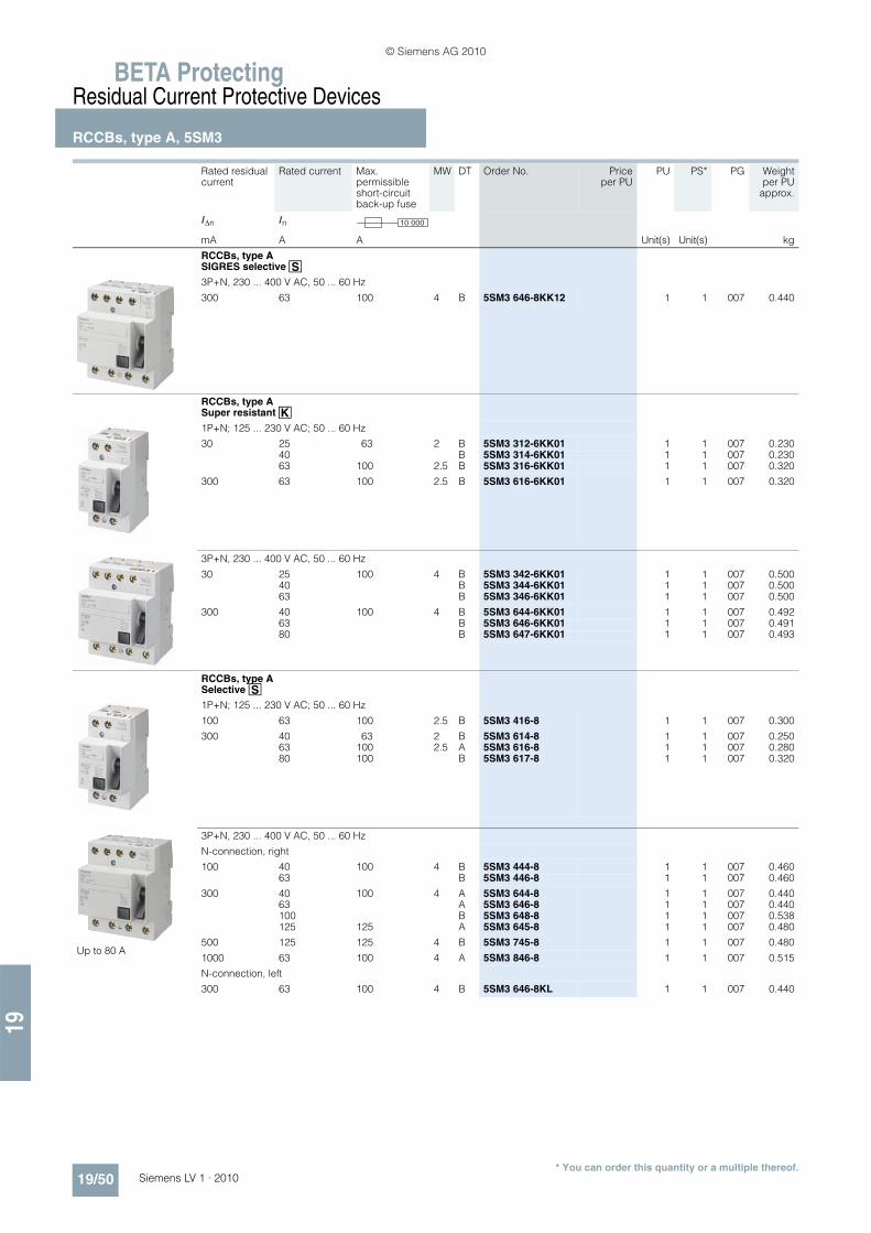
BETA ProtectingResidual Current Protective Devices
RCCBs, type A, 5SM3
19/50 Siemens LV 1 · 2010
19
* You can order this quantity or a multiple thereof.
RCCBs, type A SIGRES selective î
3P+N, 230 ... 400 V AC, 50 ... 60 Hz
300 63 100 4 B 5SM3 646-8KK12 1 1 007 0.440
RCCBs, type A Super resistant æ
1P+N; 125 ... 230 V AC; 50 ... 60 Hz
30 25 63 2 B 5SM3 312-6KK01 1 1 007 0.23040 B 5SM3 314-6KK01 1 1 007 0.23063 100 2.5 B 5SM3 316-6KK01 1 1 007 0.320
300 63 100 2.5 B 5SM3 616-6KK01 1 1 007 0.320
3P+N, 230 ... 400 V AC, 50 ... 60 Hz
30 25 100 4 B 5SM3 342-6KK01 1 1 007 0.50040 B 5SM3 344-6KK01 1 1 007 0.50063 B 5SM3 346-6KK01 1 1 007 0.500
300 40 100 4 B 5SM3 644-6KK01 1 1 007 0.49263 B 5SM3 646-6KK01 1 1 007 0.49180 B 5SM3 647-6KK01 1 1 007 0.493
RCCBs, type A Selective î
1P+N; 125 ... 230 V AC; 50 ... 60 Hz
100 63 100 2.5 B 5SM3 416-8 1 1 007 0.300
300 40 63 2 B 5SM3 614-8 1 1 007 0.25063 100 2.5 A 5SM3 616-8 1 1 007 0.28080 100 B 5SM3 617-8 1 1 007 0.320
Up to 80 A
3P+N, 230 ... 400 V AC, 50 ... 60 Hz
N-connection, right
100 40 100 4 B 5SM3 444-8 1 1 007 0.46063 B 5SM3 446-8 1 1 007 0.460
300 40 100 4 A 5SM3 644-8 1 1 007 0.44063 A 5SM3 646-8 1 1 007 0.440100 B 5SM3 648-8 1 1 007 0.538125 125 A 5SM3 645-8 1 1 007 0.480
500 125 125 4 B 5SM3 745-8 1 1 007 0.480
1000 63 100 4 A 5SM3 846-8 1 1 007 0.515
N-connection, left
300 63 100 4 B 5SM3 646-8KL 1 1 007 0.440
Rated residual current
Rated current Max. permissible short-circuit back-up fuse
MW DT Order No. Priceper PU
PU PS* PG Weightper PU
approx.
I�n In
mA A A Unit(s) Unit(s) kg
10 000
© Siemens AG 2010

19
BETA ProtectingResidual Current Protective Devices
SIQUENCE, universal current-sensitive RCCBstype B and type B+, 5SM3 and 5SU1
19/51Siemens LV 1 · 2010* You can order this quantity or a multiple thereof.
■ Overview
Frequency converters, medical devices and UPS systems are seeing increasing use in industry. Smooth DC residual currents or currents with low residual ripple may occur in the event of faults on these devices.
Type A residual current protective devices are unable to detect these smooth DC residual currents. Furthermore, such smooth DC residual currents make Type A devices increasingly insensi-tive to AC residual currents and pulsating DC residual currents. Hence if a fault occurs, there is no tripping and the desired pro-tection function is no longer assured.
UC-sensitive residual current protective devices of Types B and B+ have an additional transformer which is supplied with a con-trol signal. Hence it is possible to evaluate the change of the transformer's operating range caused by smooth DC residual currents. The desired protection function is thus assured.
The residual current protective devices of Type B are suitable for use in three-phase current systems before input circuits with rec-tifiers. They are not intended for use in DC systems and in net-works with operating frequencies other than 50 or 60 Hz.
The devices in this series are designed as residual current oper-ated circuit breakers (RCCBs) up to 80 A and as residual current circuit breakers with integral overcurrent protection (RCBOs) for 100 A or 125 A in Characteristics C or D.
Type B+ residual current protective devices additionally offer en-hanced, preventative fire protection. In these versions, the trip-ping value is limited to a maximum of 420 mA up to 20 kHz.
■ Benefits
• Universal current-sensitive residual current protective devices detect not only AC residual currents and pulsating DC residual currents, but also smooth DC residual currents, thus ensuring the desired protective function with all types of residual cur-rent
• With type B, the tripping characteristic is adapted to the in-crease of leakage currents at higher frequencies in systems with capacitive impedances and results in increased operat-ing safety.
• Type B+ versions offer enhanced preventative fire protection and correspond to the prestandards DIN V VDE V 0664-110 and/or DIN V VDE V 0664-210 and VdS Directive 3501.
• The RCBO is a compact device for up to 125 A. It provides not only personnel, property and fire protection but also overload and short-circuit protection for cables. This enables great sav-ings on wiring and installation costs.
• All RCBOs offer external remote tripping over terminals Y1/Y2. This supports implementation of central OFF circuits
■ Selection and ordering data
Rated residual current
Rated current Max. permissi-ble short-circuit back-up fuse
MW DT Order No. Priceper PU
PU PS* PG Weightper PU
approx.
I�n InmA A A Unit(s) Unit(s) kg
SIQUENCE RCCBs, type B Super resistant æ
1P+N; 230 V AC; 50 ... 60 Hz
30 16 100 4 A 5SM3 321-4 1 1 015 0.59025 A 5SM3 322-4 1 1 015 0.59040 A 5SM3 324-4 1 1 015 0.58863 A 5SM3 326-4 1 1 015 0.591
300 16 100 4 A 5SM3 621-4 1 1 015 0.60025 A 5SM3 622-4 1 1 015 0.60040 A 5SM3 624-4 1 1 015 0.59163 A 5SM3 626-4 1 1 015 0.586
3P+N, 230 ... 400 V AC, 50 ... 60 Hz
30 25 100 4 A 5SM3 342-4 1 1 015 0.60040 A 5SM3 344-4 1 1 015 0.60063 A 5SM3 346-4 1 1 015 0.60080 B 5SM3 347-4 1 1 015 0.600
300 25 100 4 } 5SM3 642-4 1 1 015 0.52040 A 5SM3 644-4 1 1 015 0.52063 A 5SM3 646-4 1 1 015 0.52080 B 5SM3 647-4 1 1 015 0.520
500 63 100 4 B 5SM3 746-4 1 1 015 0.52080 B 5SM3 747-4 1 1 015 0.520
SIQUENCE RCCBs, type B Selective î
3P+N, 230 ... 400 V AC, 50 ... 60 Hz
300 63 100 4 B 5SM3 646-5 1 1 015 0.52080 B 5SM3 647-5 1 1 015 0.520
500 63 100 4 B 5SM3 746-5 1 1 015 0.52080 B 5SM3 747-5 1 1 015 0.520
10 000
© Siemens AG 2010

BETA ProtectingResidual Current Protective DevicesSIQUENCE, universal current-sensitive RCCBs type B and type B+, 5SM3 and 5SU1
19/52 Siemens LV 1 · 2010
19
* You can order this quantity or a multiple thereof.
SIQUENCE RCCBs, type B+ Super resistant æ
1P+N; 230 V AC; 50 ... 60 Hz
30 16 100 4 C 5SM3 321-4KK14 1 1 015 0.58725 C 5SM3 322-4KK14 1 1 015 0.60040 C 5SM3 324-4KK14 1 1 015 0.60063 C 5SM3 326-4KK14 1 1 015 0.600
300 16 100 4 C 5SM3 621-4KK14 1 1 015 0.60025 C 5SM3 622-4KK14 1 1 015 0.60040 C 5SM3 624-4KK14 1 1 015 0.60063 C 5SM3 626-4KK14 1 1 015 0.600
3P+N, 230 ... 400 V AC, 50 ... 60 Hz
30 25 100 4 C 5SM3 342-4KK14 1 1 015 0.60040 C 5SM3 344-4KK14 1 1 015 0.60063 C 5SM3 346-4KK14 1 1 015 0.60080 C 5SM3 347-4KK14 1 1 015 0.600
300 25 100 4 C 5SM3 642-4KK14 1 1 015 0.60040 C 5SM3 644-4KK14 1 1 015 0.60063 C 5SM3 646-4KK14 1 1 015 0.60080 C 5SM3 647-4KK14 1 1 015 0.600
SIQUENCE RCCBs, type B+ Selective î
3P+N, 230 ... 400 V AC, 50 ... 60 Hz
300 63 100 4 C 5SM3 646-5KK14 1 1 015 0.60080 C 5SM3 647-5KK14 1 1 015 0.600
SIQUENCE RCBOs, type B Super resistant æ,rated switching capacity 10 kA
4P; 400 V AC; 50 ... 60 Hz
Characteristic C
30 100 11 B 5SU1 374-7AK81 1 1 017 2.050125 B 5SU1 374-7AK82 1 1 017 2.050
300 100 11 B 5SU1 674-7AK81 1 1 017 2.050125 B 5SU1 674-7AK82 1 1 017 2.050
Characteristic D
30 100 11 B 5SU1 374-8AK81 1 1 017 2.050
300 100 11 B 5SU1 674-8AK81 1 1 017 2.050
4P; 480 V AC; 50 ... 60 Hz
Characteristic C
300 100 11 B 5SU1 674-7CK81 1 1 017 2.050125 B 5SU1 674-7CK82 1 1 017 2.050
SIQUENCE RCBOs, type B Selective æ,rated switching capacity 10 kA
4P; 400 V AC; 50 ... 60 Hz
Characteristic C
300 125 11 B 5SU1 674-7BK82 1 1 017 1.950
Characteristic D
300 100 11 B 5SU1 674-8BK81 1 1 017 1.950
Rated residual current
Rated current Max. permissi-ble short-circuit back-up fuse
MW DT Order No. Priceper PU
PU PS* PG Weightper PU
approx.
I�n InmA A A Unit(s) Unit(s) kg
10 000
© Siemens AG 2010

19
BETA ProtectingResidual Current Protective Devices
SIQUENCE, universal current-sensitive RCCBstype B and type B+, 5SM3 and 5SU1
19/53Siemens LV 1 · 2010* You can order this quantity or a multiple thereof.
■ More information
More information about SIQUENCE residual current protective devices, universal-current sensitive RCCBs type B and type B+, 5SM3 and 5SU1, can be found in Catalog ET B1 · 2010. You can download the up-to-date catalog from www.siemens.com/e-installation-catalogs.
SIQUENCE RCBOs, type B+ Super resistant æ,rated switching capacity 10 kA
4P; 400 V AC; 50 ... 60 Hz
Characteristic C
30 100 11 C 5SU1 374-7DK81 1 1 017 2.067125 C 5SU1 374-7DK82 1 1 017 2.053
300 100 11 C 5SU1 674-7DK81 1 1 017 2.069125 C 5SU1 674-7DK82 1 1 017 2.088
Characteristic D
30 100 11 C 5SU1 374-8DK81 1 1 017 2.084
300 100 11 C 5SU1 674-8DK81 1 1 017 2.082
4P; 480 V AC; 50 ... 60 Hz
Characteristic C
300 100 11 C 5SU1 674-7FK81 1 1 017 2.050125 C 5SU1 674-7FK82 1 1 017 2.050
SIQUENCE RCBOs, type B+ Selective î,rated switching capacity 10 kA
4P; 400 V AC; 50 ... 60 Hz
Characteristic C
300 125 11 C 5SU1 674-7EK82 1 1 017 2.082
Characteristic D
300 100 11 C 5SU1 674-8EK81 1 1 017 2.078
Rated residual current
Rated current Max. permissi-ble short-circuit back-up fuse
MW DT Order No. Priceper PU
PU PS* PG Weightper PU
approx.
I�n InmA A A Unit(s) Unit(s) kg
10 000
© Siemens AG 2010

BETA ProtectingResidual Current Protective Devices
Additional components
19/54 Siemens LV 1 · 2010
19
* You can order this quantity or a multiple thereof.
■ Overview
Auxiliary switches (AS) signal the contact position of the RCCB.
Remote-controlled mechanisms are used for the remote ON/OFF switching of RCCBs. They also enable local manual switching. A blocking function permits maintenance work. If the RCCB is tripped, an acknowledgment must be carried out prior to switch-ing back on.
The leakage current measurement device detects the leakage currents - like the circuit breaker - thus providing a direct state-ment as to the current loading of the RCCB. It is used to measure leakage currents up to 300 mA. This requires a voltmeter with an internal resistance more than 1 M�/V and a measuring range for AC voltages of Ueff = 1 mV to 2 V. For the fault-free operation of an RCCB, the measured leakage current should be no greater than 1/3 of the rated residual current.
■ Benefits
• Using captive brackets, the remote-controlled mechanism can be attached (or retroffitted) to the right-hand side of the basic device without the need for tools
• Bus systems, such as instabus KNX, AS-Interface bus or PROFIBUS, can be integrated in the communication over bi-nary inputs
• The leakage current measurement device enables the sys-tematic selection of the rated residual current, thus helping to prevent the inadvertent tripping of RCCBs.
■ Selection and ordering data
Version MW DT Order No. Priceper PU
PU PS* PG Weightper PU
approx.
Unit(s) Unit(s) kg
Auxiliary switches (AS)For 5SM3 RCCBs up to 80 A
1 NO + 1 NC 0.5 } 5SW3 300 1 1/10 008 0.042
2 NC 0.5 C 5SW3 301 1 1/10 008 0.042
2 NO 0.5 A 5SW3 302 1 1/10 008 0.042
Auxiliary switches (AS)For 5SM3 RCCBs, 100 ... 125 A, 3P+N
1 NO + 1 NC 0.5 B 5SW3 330 1 1 008 0.040
Remote-controlled mechanisms (RC) For 5SM3 RCCBs up to 80 A
Rated voltage Un = 230 V AC 3.5 B 5ST3 051 1 1 027 0.395
Leakage current measurement device
Rated voltage Un = 500 V AC; 50 ... 60 Hz, 4P
4 B 5SM1 930-0 1 1 008 0.430
Rated residual current I�n = 0 ... 300 mA
Rated current In = 63 A
Covers for connection terminals
For residual current operated circuit breakers up to 80 A, sealable (2 units in plastic bag)
2 A 5SW3 010 1 1/50 008 0.003
2.5 A 5SW3 011 1 1/50 008 0.004
4 A 5SW3 008 1 1/50 008 0.006
I2_1
3711
a
© Siemens AG 2010

19
BETA ProtectingResidual Current Protective Devices
Additional componentsRC units, type A, 5SM2
19/55Siemens LV 1 · 2010* You can order this quantity or a multiple thereof.
■ More information
Gossen-Metrawatt offers suitable test devices for RCCB function tests and for testing protective measures.
Information is available at:
Gossen-Metrawatt GmbH Thomas-Mann-Str. 16-20 D-90471 Nuremberg GermanyTel. +49 (0) 9 11/86 02-111Fax +49 (0) 9 11/86 02-777www.gmc-instruments.comE-mail: [email protected]
■ Overview
RC units, type A, 5SM2
RC units of type A can be used in all systems up to 240/415 V AC. They trip in the event of both sinusoidal AC fault currents and pulsating DC residual currents.
RCCBs with a rated residual current of maximum 30 mA are used for personnel, material and fire protection, and for addi-tional protection against direct contact.
Devices with a rated residual current of maximum 300 mA are used as preventative fire protection in case of insulation faults.
RC units are combined with MCBs with characteristics A, B, C and D, provided that these are available in the MCB range. The two components are simply plugged together without the need for any tools.
They then form a combination of RCCB and MCB for personnel, fire and line protection.
Super resistantæ
Super resistant (short-time delayed) RC units satisfy the maxi-mum permissible break times for instantaneous devices. How-ever, by implementing a short-time delay they prevent unneces-sary trippings, and thus plant faults, when pulse-shaped leakage currents occur - as is the case when capacitors are switched on.
Selectiveî
Can be used as upstream group switch for selective tripping contrary to a downstream, instantaneous or super resistant RCCB.
The dimensioning of the rated residual current depends on the size of the plant.
■ Benefits
• Our wide variety of RC unit types and comprehensive range of miniature circuit breakers offer a huge spectrum of combina-tions for all applications
• All devices have an current withstand capability of more than 1 kA, thus ensuring safe and reliable operation
• All additional components for miniature circuit breakers can be retrofitted on the right-hand side
• All 100 A and 125 A RC units offer external remote tripping over terminals Y1/Y2. This supports implementation of central OFF circuits
• Both components can be simply plugged into each other and secured with captive metal brackets - no tools required. This saves considerable time when mounting.
Locking devices
for RCCBs up to 80 A, sealable and lockable
4.5 mm hole diameter B 5SW3 303 1 10 008 0.008
Padlocks
For 5SW3 303 locking device } 5ST3 802 1 1 027 0.027
Locking devices with padlock
Comprising 5SW3 303 locking device and 5ST3 802 padlock
B 5SW3 312 1 set 1 set 008 0.035
Version MW DT Order No. Priceper PU
PU PS* PG Weightper PU
approx.
Unit(s) Unit(s) kg
© Siemens AG 2010

BETA ProtectingResidual Current Protective Devices
RC units, type A, 5SM2
19/56 Siemens LV 1 · 2010
19
* You can order this quantity or a multiple thereof.
■ Selection and ordering data
Rated residual current
Rated current MW DT Order No. Priceper PU
PU PS* PG Weightper PU
approx.
I�n InmA A Unit(s) Unit(s) kg
RC units, type A instantaneous
For 5SY miniature circuit breakers, but not for 5SY5 and 5SY6 0..
2P, 230 ... 400 V AC, 50 ... 60 Hz
10 0.3 ... 16 2 B 5SM2 121-6 1 1 007 0.180
30 0.3 ... 40 } 5SM2 322-6 1 1 007 0.170300 A 5SM2 622-6 1 1 007 0.170
30 0.3 ... 63 A 5SM2 325-6 1 1 007 0.170100 B 5SM2 425-6 1 1 007 0.170300 B 5SM2 625-6 1 1 007 0.170500 B 5SM2 725-6 1 1 007 0.170
For 5SY miniature circuit breakers, but not for 5SY5 and 5SY6 0..
3P, 230 ... 400 V AC, 50 ... 60 Hz
30 0.3 ... 40 3 A 5SM2 332-6 1 1 007 0.260300 A 5SM2 632-6 1 1 007 0.260
30 0.3 ... 63 B 5SM2 335-6 1 1 007 0.260100 B 5SM2 435-6 1 1 007 0.260300 B 5SM2 635-6 1 1 007 0.260500 B 5SM2 735-6 1 1 007 0.260
For 5SY miniature circuit breakers, but not for 5SY5 and 5SY6 0..
4P, 230 ... 400 V AC, 50 ... 60 Hz
30 0.3 ... 40 3 } 5SM2 342-6 1 1 007 0.290300 } 5SM2 642-6 1 1 007 0.290
30 0.3 ... 63 A 5SM2 345-6 1 1 007 0.290100 B 5SM2 445-6 1 1 007 0.290300 A 5SM2 645-6 1 1 007 0.290500 A 5SM2 745-6 1 1 007 0.290
For 5SP4 miniature circuit breakers (B and C characteristic)
2P; 125 ... 230 V AC, 50 ... 60 Hz
30 80 ... 100 3.5 B 5SM2 327-6 1 1 007 0.410300 B 5SM2 627-6 1 1 007 0.410
For 5SP4 miniature circuit breakers (B and C characteristic)
4P; 230 ... 400 V AC, 50 ... 60 Hz
30 80 ... 100 5 B 5SM2 347-6 1 1 007 0.630300 A 5SM2 647-6 1 1 007 0.630
© Siemens AG 2010

19
BETA ProtectingResidual Current Protective Devices
RC units, type A, 5SM2
19/57Siemens LV 1 · 2010* You can order this quantity or a multiple thereof.
RC units, type A Super resistantæ
For 5SY miniature circuit breakers, but not for 5SY5 and 5SY6 0..
2P, 230 ... 400 V AC, 50 ... 60 Hz
30 0.3 ... 40 2 B 5SM2 322-6KK01 1 1 007 0.350
30 0.3 ... 63 B 5SM2 325-6KK01 1 1 007 0.350
3P, 230 ... 400 V AC, 50 ... 60 Hz
30 0.3 ... 40 3 B 5SM2 332-6KK01 1 1 007 0.365
30 0.3 ... 63 B 5SM2 335-6KK01 1 1 007 0.365
4P, 230 ... 400 V AC, 50 ... 60 Hz
30 0.3 ... 40 3 B 5SM2 342-6KK01 1 1 007 0.290
30 0.3 ... 63 B 5SM2 345-6KK01 1 1 007 0.290
RC units, type A Selective î
For 5SY miniature circuit breakers, but not for 5SY5 and 5SY6 0..
2P, 230 ... 400 V AC, 50 ... 60 Hz
300 0.3 ... 40 2 A 5SM2 622-8 1 1 007 0.170
300 0.3 ... 63 B 5SM2 625-8 1 1 007 0.170
3P, 230 ... 400 V AC, 50 ... 60 Hz
1000 0.3 ... 40 3 B 5SM2 832-8 1 1 007 0.365
300 0.3 ... 63 3 B 5SM2 635-8 1 1 007 0.260500 B 5SM2 735-8 1 1 007 0.4001000 B 5SM2 835-8 1 1 007 0.260
For 5SY miniature circuit breakers, but not for 5SY5 and 5SY6 0..
4P, 230 ... 400 V AC, 50 ... 60 Hz
300 0.3 ... 63 3 A 5SM2 645-8 1 1 007 0.290500 A 5SM2 745-8 1 1 007 0.4001000 A 5SM2 845-8 1 1 007 0.290
For 5SP4 miniature circuit breakers (B and C characteristic)
2P; 125 ... 230 V AC, 50 ... 60 Hz
300 80 ... 100 3.5 B 5SM2 627-8 1 1 007 0.410
For 5SP4 miniature circuit breakers (B and C characteristic)
4P; 230 ... 400 V AC, 50 ... 60 Hz
300 80 ... 100 5 A 5SM2 647-8 1 1 007 0.6301000 A 5SM2 847-8 1 1 007 0.630
Rated residual current
Rated current MW DT Order No. Priceper PU
PU PS* PG Weightper PU
approx.
I�n InmA A Unit(s) Unit(s) kg
© Siemens AG 2010
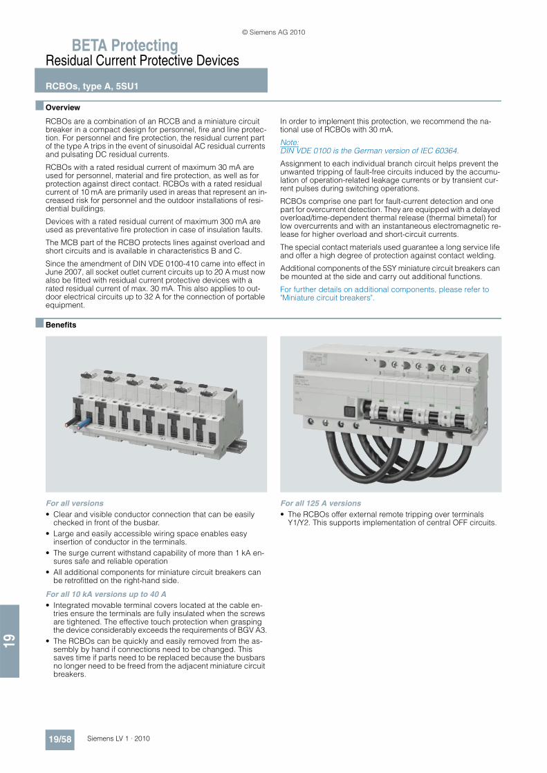
BETA ProtectingResidual Current Protective Devices
RCBOs, type A, 5SU1
19/58 Siemens LV 1 · 2010
19
■ Overview
RCBOs are a combination of an RCCB and a miniature circuit breaker in a compact design for personnel, fire and line protec-tion. For personnel and fire protection, the residual current part of the type A trips in the event of sinusoidal AC residual currents and pulsating DC residual currents.
RCBOs with a rated residual current of maximum 30 mA are used for personnel, material and fire protection, as well as for protection against direct contact. RCBOs with a rated residual current of 10 mA are primarily used in areas that represent an in-creased risk for personnel and the outdoor installations of resi-dential buildings.
Devices with a rated residual current of maximum 300 mA are used as preventative fire protection in case of insulation faults.
The MCB part of the RCBO protects lines against overload and short circuits and is available in characteristics B and C.
Since the amendment of DIN VDE 0100-410 came into effect in June 2007, all socket outlet current circuits up to 20 A must now also be fitted with residual current protective devices with a rated residual current of max. 30 mA. This also applies to out-door electrical circuits up to 32 A for the connection of portable equipment.
In order to implement this protection, we recommend the na-tional use of RCBOs with 30 mA.
Note:DIN VDE 0100 is the German version of IEC 60364.
Assignment to each individual branch circuit helps prevent the unwanted tripping of fault-free circuits induced by the accumu-lation of operation-related leakage currents or by transient cur-rent pulses during switching operations.
RCBOs comprise one part for fault-current detection and one part for overcurrent detection. They are equipped with a delayed overload/time-dependent thermal release (thermal bimetal) for low overcurrents and with an instantaneous electromagnetic re-lease for higher overload and short-circuit currents.
The special contact materials used guarantee a long service life and offer a high degree of protection against contact welding.
Additional components of the 5SY miniature circuit breakers can be mounted at the side and carry out additional functions.
For further details on additional components, please refer to "Miniature circuit breakers".
■ Benefits
For all versions • Clear and visible conductor connection that can be easily
checked in front of the busbar.• Large and easily accessible wiring space enables easy
insertion of conductor in the terminals.• The surge current withstand capability of more than 1 kA en-
sures safe and reliable operation• All additional components for miniature circuit breakers can
be retrofitted on the right-hand side.
For all 10 kA versions up to 40 A• Integrated movable terminal covers located at the cable en-
tries ensure the terminals are fully insulated when the screws are tightened. The effective touch protection when grasping the device considerably exceeds the requirements of BGV A3.
• The RCBOs can be quickly and easily removed from the as-sembly by hand if connections need to be changed. This saves time if parts need to be replaced because the busbars no longer need to be freed from the adjacent miniature circuit breakers.
For all 125 A versions• The RCBOs offer external remote tripping over terminals
Y1/Y2. This supports implementation of central OFF circuits.
© Siemens AG 2010

19
BETA ProtectingResidual Current Protective Devices
RCBOs, type A, 5SU1
19/59Siemens LV 1 · 2010* You can order this quantity or a multiple thereof.
■ Selection and ordering data
Tripping characteristic B Tripping characteristic C
Rated residual current
Rated current
MW DT Order No. Priceper PU
PG DT Order No. Priceper PU
PU PS* PG Weightper PU
approx.I�n InmA A Unit(s) Unit(s) kg
RCBOs, type A Instantaneous
1P+N; 230 V AC; 50 ... 60 Hz
30 6 2 A 5SU1 356-6KK06 011 A 5SU1 356-7KK06 1 1 011 0.2608 -- B 5SU1 356-7KK08 1 1 011 0.260
10 A 5SU1 356-6KK10 011 } 5SU1 356-7KK10 1 1 011 0.26013 B 5SU1 356-6KK13 011 A 5SU1 356-7KK13 1 1 011 0.26016 } 5SU1 356-6KK16 011 } 5SU1 356-7KK16 1 1 011 0.260
20 B 5SU1 356-6KK20 011 B 5SU1 356-7KK20 1 1 011 0.26025 B 5SU1 356-6KK25 011 A 5SU1 356-7KK25 1 1 011 0.26032 B 5SU1 356-6KK32 011 B 5SU1 356-7KK32 1 1 011 0.26040 B 5SU1 356-6KK40 011 B 5SU1 356-7KK40 1 1 011 0.260
300 6 2 B 5SU1 656-6KK06 011 B 5SU1 656-7KK06 1 1 011 0.26010 B 5SU1 656-6KK10 011 A 5SU1 656-7KK10 1 1 011 0.26013 B 5SU1 656-6KK13 011 B 5SU1 656-7KK13 1 1 011 0.26016 B 5SU1 656-6KK16 011 A 5SU1 656-7KK16 1 1 011 0.260
20 B 5SU1 656-6KK20 011 B 5SU1 656-7KK20 1 1 011 0.26025 B 5SU1 656-6KK25 011 B 5SU1 656-7KK25 1 1 011 0.26032 B 5SU1 656-6KK32 011 B 5SU1 656-7KK32 1 1 011 0.26040 B 5SU1 656-6KK40 011 B 5SU1 656-7KK40 1 1 011 0.260
RCBOs, type A Instantaneous
1P+N; 230 V AC; 50 ... 60 Hz
10 6 2 B 5SU1 154-6KK06 011 B 5SU1 154-7KK06 1 1 011 0.26010 B 5SU1 154-6KK10 011 B 5SU1 154-7KK10 1 1 011 0.26013 B 5SU1 154-6KK13 011 B 5SU1 154-7KK13 1 1 011 0.26016 B 5SU1 154-6KK16 011 } 5SU1 154-7KK16 1 1 011 0.260
30 6 2 B 5SU1 354-6KK06 011 } 5SU1 354-7KK06 1 1 011 0.2608 -- B 5SU1 354-7KK08 1 1 011 0.260
10 B 5SU1 354-6KK10 011 } 5SU1 354-7KK10 1 1 011 0.26013 B 5SU1 354-6KK13 011 B 5SU1 354-7KK13 1 1 011 0.26016 } 5SU1 354-6KK16 011 } 5SU1 354-7KK16 1 1 011 0.260
20 B 5SU1 354-6KK20 011 B 5SU1 354-7KK20 1 1 011 0.26025 B 5SU1 354-6KK25 011 B 5SU1 354-7KK25 1 1 011 0.26032 B 5SU1 354-6KK32 011 B 5SU1 354-7KK32 1 1 011 0.26040 B 5SU1 354-6KK40 011 B 5SU1 354-7KK40 1 1 011 0.260
300 6 2 B 5SU1 654-6KK06 011 B 5SU1 654-7KK06 1 1 011 0.26010 B 5SU1 654-6KK10 011 B 5SU1 654-7KK10 1 1 011 0.26013 B 5SU1 654-6KK13 011 B 5SU1 654-7KK13 1 1 011 0.26016 B 5SU1 654-6KK16 011 B 5SU1 654-7KK16 1 1 011 0.260
20 B 5SU1 654-6KK20 011 B 5SU1 654-7KK20 1 1 011 0.26025 B 5SU1 654-6KK25 011 B 5SU1 654-7KK25 1 1 011 0.26032 B 5SU1 654-6KK32 011 B 5SU1 654-7KK32 1 1 011 0.26040 B 5SU1 654-6KK40 011 B 5SU1 654-7KK40 1 1 011 0.260
2P; 230 V AC; 50 ... 60 Hz
30 6 3 B 5SU1 324-6FA06 011 B 5SU1 324-7FA06 1 1 011 0.40310 } 5SU1 324-6FA10 011 } 5SU1 324-7FA10 1 1 011 0.40313 B 5SU1 324-6FA13 011 B 5SU1 324-7FA13 1 1 011 0.40316 } 5SU1 324-6FA16 011 } 5SU1 324-7FA16 1 1 011 0.403
20 B 5SU1 324-6FA20 011 B 5SU1 324-7FA20 1 1 011 0.40325 B 5SU1 324-6FA25 011 B 5SU1 324-7FA25 1 1 011 0.40332 B 5SU1 324-6FA32 011 B 5SU1 324-7FA32 1 1 011 0.40340 B 5SU1 324-6FA40 011 B 5SU1 324-7FA40 1 1 011 0.403
6 0003
10 0003
10 0003
© Siemens AG 2010

BETA ProtectingResidual Current Protective Devices
RCBOs, type A, 5SU1
19/60 Siemens LV 1 · 2010
19
* You can order this quantity or a multiple thereof.
Note:The same additional components are used for RCBOs as for miniature circuit breakers. See "Miniature circuit breakers".
■ More information
More information about RCBOs, type A, 5SU1 can be found in Catalog ET B1 · 2010. The current issue of the catalog can be downloaded from www.siemens.com/e-installation-catalogs.
RCBOs, type A Instantaneous
2P; 400 V AC; 50 ... 60 Hz
30 125 6.5 B 5SU1 324-6KK82 011 B 5SU1 324-7KK82 1 1 011 0.930
300 125 B 5SU1 624-6KK82 011 B 5SU1 624-7KK82 1 1 011 0.930
4P; 400 V AC; 50 ... 60 Hz
30 125 11 B 5SU1 344-6KK82 011 B 5SU1 344-7KK82 1 1 011 1.900
300 125 B 5SU1 644-6KK82 011 B 5SU1 644-7KK82 1 1 011 1.900
RCBOs, type A Super resistant æ
1P+N; 230 V AC; 50 ... 60 Hz
30 10 2 -- B 5SU1 354-7VK10 1 1 011 0.26016 -- B 5SU1 354-7VK16 1 1 011 0.26020 -- B 5SU1 354-7VK20 1 1 011 0.26025 -- B 5SU1 354-7VK25 1 1 011 0.260
RCBOs, type A Selective î
2P; 400 V AC; 50 ... 60 Hz
300 125 6.5 B 5SU1 624-6WK82 011 B 5SU1 624-7WK82 1 1 011 0.930
4P; 400 V AC; 50 ... 60 Hz
300 125 11 B 5SU1 644-6WK82 011 B 5SU1 644-7WK82 1 1 011 1.900
Version DT Order No. Priceper PU
PU PS* PG Weightper PU
approx.
Unit(s) Unit(s) kg
Handle couplers for additional components
For mounting the additional components: auxiliary switches, fault signal contacts, shunt trips and undervoltage releases onto 5SU1 RCBOs, you require a handle coupler (1 set = 5 units).
} 5ST3 805-1 1 set 1 set 027 0.008
Tripping characteristic B Tripping characteristic C
Rated residual current
Rated current
MW DT Order No. Priceper PU
PG DT Order No. Priceper PU
PU PS* PG Weightper PU
approx.I�n InmA A Unit(s) Unit(s) kg
10 000
10 000
10 0003
10 000
10 000
© Siemens AG 2010

19
BETA ProtectingResidual Current Protective Devices
Busbars
19/61Siemens LV 1 · 2010
■ Overview
4-pole 5SM3 RCCBs are bus-mounted either together or in com-bination with miniature circuit breakers. RCCBs with an N con-ductor connection on the left-hand side facilitate installation be-cause normal busbars are used, as for miniature circuit breakers.
Busbars are available in 10 mm2 and 16 mm2.
The extremely flexible 5ST3 6 busbar system with fixed lengths enables installation in any length as the busbars can be over-lapped.
No further need for time-consuming tasks, such as cutting, cut-ting to length, deburring, cleaning of cut surfaces and mounting of end caps.
Any free pins on the busbars can be made finger-safe by cover-ing with touch protection.
If several RCBOs are bus-mounted together, this is implemented with two-phase busbars, which are used as 1+N busbars.
■ Benefits
• Connection of miniature circuit breakers to 4-pole RCCBs with N-connection right with three-phase busbar, using busbar specially designed for this application. No cutting or end caps required.
• Connection of miniature circuit breakers to 4-pole RCCBs with N-connection left with three-phase busbar that can be cut. No additional items to be stored and busbars that are always available.
• Connection of 1P+N RCBOs with two-phase busbar. No cut-ting or end caps required.
• Bus mounting of RCCBs on busbar (three-phase +N) that can be cut. A proven and frequently used application
© Siemens AG 2010

BETA ProtectingResidual Current Protective Devices
Busbars
19/62 Siemens LV 1 · 2010
19
* You can order this quantity or a multiple thereof.
■ Selection and ordering data
Version Pin spacing
Length DT Order No. Priceper PU
PU PS* PG Weightper PU
approx.
MW mm Unit(s) Unit(s) kg
5ST3 6 busbar systems, fixed lengths, cannot be cut, fully insulated
For 1 RC block 4P, N connection right, and 8 MCBs 1P
• Three-phase 10 mm2 1 210 A 5ST3 624 1 10 027 0.075
• Three-phase 16 mm2 1 210 A 5ST3 654 1 10 027 0.114
For 6 RCBOs 1P+N together
• Two-phase 10 mm2 210 A 5ST3 608 1 10 027 0.048
• Two-phase 16 mm2 210 A 5ST3 638 1 10 027 0.076
5ST3 7 busbar systems, 12 MW, can be cut, with end caps
For 1 RC block 4P, N connection right, and 8 MCBs 1P
• Three-phase 16 mm2 A 5ST3 717 1 25 027 0.150
For 6 RCBOs 1P+N
• Two-phase 10 mm2 1 216 A 5ST3 734 1 1 027 0.060
• Two-phase 16 mm2 1 216 A 5ST3 704 1 1 027 0.060
5ST3 7 busbar systems, with end caps, can be cut, finger-safe
For RCBO 1P+N and MCB 2P
• Four-phase 10 mm4 1 1008 A 5ST3 770-2 1 10 027 0.400• Four-phase 16 mm4 1 1008 A 5ST3 770-3 1 10 027 0.550
For RC block 4P, N connection right and 6 MCBs 1P+N
• Four-phase 10 mm4 1 288 A 5ST3 770-4 1 10 027 0.100• Four-phase 16 mm4 1 288 A 5ST3 770-5 1 10 027 0.160
End caps for 5ST3 7, can be cut
For two-phase busbars } 5ST3 750 1 10 027 0.001
Touch protection
For free connections, yellow (RAL 1004) A 5ST3 655 1 10 027 0.0035 x 1 pin
Busbars, 12 MW, with fork-type connections, can be cut, with end caps
For bus mounting RCCBs together • Three-phase + N, 16 mm2 1 216 A 5ST2 145 1 1 027 0.315
End caps for 5ST3 7, can be cut
For three-phase busbars A 5ST2 156 1 10 027 0.017
Terminals up to 35 mm2 (stranded), for direct infeed of 5ST2 145 busbar
Side-by-side mounting possible A 5ST2 157 1 5 027 0.030
© Siemens AG 2010

19
BETA ProtectingResidual Current Protective Devices
Accessories
19/63Siemens LV 1 · 2010* You can order this quantity or a multiple thereof.
■ Accessories
Version DT Order No. Priceper PU
PU PS* PG Weightper PU
approx.
Unit(s) Unit(s) kg
Terminal covers, gray
For surface mounting, degree of protection IP40, sealable, with TH 35 standard mounting rail
• Up to 2.5 MW B 5SW3 004 1 1 008 0.084
• Up to 4.5 MW B 5SW3 005 1 1 008 0.114
Wall enclosures, gray
For flush mounting, degree of protection, IP40, with TH 35 standard mounting rail
• Up to 2.5 MW B 5SW3 006 1 1/4 008 0.126
• Up to 4.5 MW B 5SW3 007 1 1 008 0.147
Molded-plastic enclosures, gray
For surface mounting, degree of protection IP54, sealable, with TH 35 standard mounting rail, with transparent hinged lid For 4.5 MW
A 5SW1 200 1 1 008 0.450
Covers
Can be assembled as mini distribution board, suitable for all devices, cover parts prepared for rail mounting of conventional label caps, comprising:
• End plates (can be snapped onto standard mounting rail)
A 5ST2 134 1 10 027 0.022
• Angle section (approx. 1 m long) A 5ST2 135 1 5 027 0.330
• Alternatively flat profile (as a cover between the rows of devices, length approx. 1 m)
B 5ST2 136 1 5 027 0.260
Fixing parts
Plastic 4 MW
B 5ST2 201 1 1 027 0.012
Inscription labels (white)
15 mm x 9 mm, 3 frames à 44 labels, any attachment and inscription, self-adhesive
B 5ST2 173 1 set 1 set 027 0.038
Labeling systems
Inscriptions on self-adhesive labels for a neat and uniform appearance in the power distribution system. The labeling program can be downloaded to your PC free of charge:
www.siemens.com/beta
Recommended ELAT-3-747 labels for printing out on standard printers can be ordered from BRADY:
www.bradycorp.com
© Siemens AG 2010

BETA ProtectingLow-Voltage Fuse Systems
NEOZED fuse systems
19/64 Siemens LV 1 · 2010
19
■ Overview
The NEOZED fuse system is primarily used in distribution tech-nology and industrial switchgear assemblies. The system is easy to use and is also approved for domestic installation.
MINIZED switch disconnectors are primarily used in switchgear assemblies and control engineering. They are approved for switching loads and also for safe switching in the event of short circuits. The MINIZED D02 is also suitable for use in the pre-counter sector in household applications in compliance with the recommendations of the BDEW (association of German utilities) according to TAB 2007.
Due to its small footprint, the NEOZED disconnector is primarily used in control engineering.
The NEOZED fuse bases are the most cost-effective solution for the application of NEOZED fuses. All NEOZED bases must be fed from the bottom to ensure that the threaded ring is insulated during removal of the fuse link. The terminals of the NEOZED bases are available in different versions and designs to support the various installation methods.
■ Benefits
MINIZED switch disconnectors • Clear and visible conductor connection that can be easily
checked. This facilitates insertion of the conductor and saves time
• With draw-out technology for off-circuit replacement of fuses. This provides enhanced safety
• The infeed of the devices can be from the top or the bottom. This enables flexible application.
NEOZED fuse bases made of molded plastic• Clear and visible conductor connection that can be easily
checked. This facilitates insertion of the conductor and saves time
• Greater safety for personnel thanks to terminals with touch protection acc. to BGV A3 (labor safety specification) at in-coming and outgoing feeder. This ensures enhanced safety
• Two type ranges with different terminals offer expanded appli-cation options.
NEOZED fuse disconnectors• With draw-out technology for off-circuit replacement of fuses.
This provides enhanced safety• Extremely narrow design with a single MW per pole. This
saves space and costs.
NEOZED fuse bases made of ceramic• Different terminal versions support a huge range of different
installation methods. This ensures greater flexibility• These bases are the most widely used devices for applica-
tions with NEOZED fuses. An unrivaled cost-effective solution.
© Siemens AG 2010

19
BETA ProtectingLow-Voltage Fuse Systems
NEOZED fuse systems
19/65Siemens LV 1 · 2010* You can order this quantity or a multiple thereof.
■ Selection and ordering data
Size Number of poles
In Identifica-tion color
MW DT Order No. Priceper PU
PU PS* PG Weightper PU
approx.
A Unit(s) Unit(s) kg
NEOZED fuse links Rated voltage 400 V AC/250 V DC operational class gG
D01 2 Pink } 5SE2 302 1 10 016 0.0064 Brown } 5SE2 304 1 10 016 0.0066 Green } 5SE2 306 1 10/500 016 0.006
10 Red } 5SE2 310 1 10/500 016 0.00713 Black A 5SE2 013-2A 1 10 016 0.00716 Gray } 5SE2 316 1 10/500 016 0.007
D02 20 Blue } 5SE2 320 1 10 016 0.01225 Yellow } 5SE2 325 1 10 016 0.01332 Black B 5SE2 332 1 10 016 0.014
35 Black } 5SE2 335 1 10 016 0.01440 Black B 5SE2 340 1 10 016 0.01450 White } 5SE2 350 1 10 016 0.015
63 Copper } 5SE2 363 1 10 016 0.016
D03 80 Blue } 5SE2 280 1 10 016 0.039100 Red } 5SE2 300 1 10 016 0.042
MINIZED switch disconnectors with fuses Using draw-out technology with touch protection to BGV A3 (adapter sleeves are not included in the scope of supply)
D02 1P 63 1.5 } 5SG7 113 1 1 016 0.145
1P+N 63 3 B 5SG7 153 1 1 016 0.267
2P 63 3 B 5SG7 123 1 1 016 0.283
3P 63 4.5 } 5SG7 133 1 1 016 0.421
3P+N 63 6 B 5SG7 163 1 1 016 0.540
Versions for Austria only, permanently fitted adapter sleeves, including fuse link
D02 3P 25 4.5 B 5SG7 133-8BA25 1 1 016 0.42035 B 5SG7 133-8BA35 1 1 016 0.42050 B 5SG7 133-8BA50 1 1 016 0.420
Locking caps
In MINIZED D02 switch disconnectors for applications in the precounter sector
C 5SH5 532 1 1 016 0.012
Reducers
For fuse links D01,in MINIZED switch disconnectors D02
C 5SH5 527 1 10/100 016 0.003
Auxiliary switches (AS)
For MINIZED switch disconnectors D02
1 NO + 1 NC 0.5 } 5ST3 010 1 1 027 0.050
2 NO A 5ST3 011 1 1 027 0.050
2 NC A 5ST3 012 1 1 027 0.050
For technical specifications, see chapter Miniature circuit breakers –> Additional components
Auxiliary switches (AS) with TEST button
For MINIZED switch disconnectors D02
1 NO + 1 NC 0.5 A 5ST3 010-2 1 1 027 0.045
2 NO A 5ST3 011-2 1 1 027 0.045
2 NC A 5ST3 012-2 1 1 027 0.045
For technical specifications, see chapter Miniature circuit breakers –> Additional components
© Siemens AG 2010

BETA ProtectingLow-Voltage Fuse Systems
NEOZED fuse systems
19/66 Siemens LV 1 · 2010
19
* You can order this quantity or a multiple thereof.
For busbars, see page 19/82 ff.1) Covers in brackets are included in the scope of supply.
Covers without brackets are not included in scope of supply.
Size Number of poles
In Matching cover1)
MW DT Order No. Priceper PU
PU PS* PG Weightper PU
approx.
A Unit(s) Unit(s) kg
MINIZED fuse switch disconnectorsFor industrial applications Using draw-out technology with touch protection BGV A3 (NEOZED adapter sleeves cannot be used)
D01 1P 16 1 A 5SG7 610 1 1 016 0.0701P+N 16 2 B 5SG7 650 1 1 016 0.1502P 16 2 B 5SG7 620 1 1 016 0.150
3P 16 3 A 5SG7 630 1 1 016 0.2203P+N 16 4 B 5SG7 660 1 1 016 0.300
NEOZED comfort bases made of molded plas-ticWith touch protection acc. to BGV A3
D01 1P 16 -- 1.5 } 5SG1 301 1 3 016 0.123D02 63 -- } 5SG1 701 1 3 016 0.120
D01 3P 16 -- 4.5 } 5SG5 301 1 1 016 0.371D02 63 -- } 5SG5 701 1 1 016 0.360
NEOZED fuse bases made of molded plastic With touch protection acc. to BGV A3
With cover
D01 1P 16 (A1) 1.5 A 5SG1 330 1 6 016 0.068D02 63 (A1) 1.5 A 5SG1 730 1 6 016 0.087
Without cover
D01 1P 16 A1 1.5 B 5SG1 331 1 6 016 0.056D02 63 A1 1.5 A 5SG1 731 1 6 016 0.080
With cover
D01 3P 16 (A2) 4.5 A 5SG5 330 1 2 016 0.216D02 63 (A2) 4.5 A 5SG5 730 1 2 016 0.252
© Siemens AG 2010

19
BETA ProtectingLow-Voltage Fuse Systems
NEOZED fuse systems
19/67Siemens LV 1 · 2010* You can order this quantity or a multiple thereof.
1) Covers in brackets are included in the scope of supply. Covers without brackets are not included in the scope of supply.
2) For terminal versions, see page 19/69.
Size Number of poles
In Matching cover1)
Terminals2) MW DT Order No. Priceper PU
PU PS* PG Weightper PU
approx.
A Unit(s) Unit(s) kg
NEOZED fuse bases made of ceramic
With cover
D01 1P 16 (A4) BB 1.5 } 5SG1 553 1 6 016 0.083D02 63 (A10) SS 1.5 } 5SG1 653 1 6 016 0.093D02 63 (A10) KS 1.5 } 5SG1 693 1 6 016 0.090
Without cover
D01 1P 16 A4 BB 1.5 B 5SG1 595 1 6 016 0.071D02 63 A10 SS 1.5 } 5SG1 655 1 6 016 0.081D02 63 A10 KS 1.5 B 5SG1 695 1 6 016 0.078D03 100 A6, A9 KS 2.5 A 5SG1 812 1 10 016 0.176
For screw connection only, without cover
D01 1P 16 A4 BB 1.5 B 5SG1 590 1 6 016 0.061D02 63 A10 SS 1.5 B 5SG1 650 1 6 016 0.078D03 100 A6, A9 KS 2.5 B 5SG1 810 1 10 016 0.176
With cap
D01 1P 16 (A8) BB 1.5 } 5SG1 594 1 6 016 0.105D02 63 (A8) SS 1.5 B 5SG1 694 1 6 016 0.115D03 100 (A9) KS 2.5 B 5SG1 813 1 10 016 0.242
With cover
D01 3P 16 (A5) BB 4.5 } 5SG5 553 1 2 016 0.263D02 63 (A11) SS 4.5 } 5SG5 653 1 2 016 0.240D02 63 (A11) KS 4.5 } 5SG5 693 1 2 016 0.290
Without cover
D01 3P 16 A5 BB 4.5 B 5SG5 555 1 2 016 0.228D02 63 A11 SS 4.5 B 5SG5 655 1 2 016 0.265D02 63 A11 KS 4.5 B 5SG5 695 1 2 016 0.255
For screw connection only, without cover
D01 3P 16 A5 BB 4.5 B 5SG5 550 1 2 016 0.228D02 63 A11 SS 4.5 B 5SG5 650 1 2 016 0.260D02 63 A11 KS 4.5 B 5SG5 690 1 2 016 0.250
NEOZED covers
Made of molded plastic, plug-infor fuse base made of molded plastic
D01, D02
A1 1.5 C 5SH5 244 1 15 016 0.008
D01, D02
A2 4.5 C 5SH5 245 1 5 016 0.017
For fuse bases made of ceramic
D01 A4 1.5 B 5SH5 251 1 15 016 0.012D02 A10 1.5 B 5SH5 253 1 15 016 0.020
© Siemens AG 2010

BETA ProtectingLow-Voltage Fuse Systems
NEOZED fuse systems
19/68 Siemens LV 1 · 2010
19
* You can order this quantity or a multiple thereof.
Size Matching cover
MW DT Order No. Priceper PU
PU PS* PG Weightper PU
approx.
Unit(s) Unit(s) kg
NEOZED covers
D01 A5 4.5 C 5SH5 252 1 5 016 0.035D02 A11 4.5 C 5SH5 254 1 5 016 0.045
Screw-on
D03 A6 2.5 B 5SH5 233 1 20 016 0.021
NEOZED caps
Made of molded plastic, plug-in
D01, D02 A8 B 5SH5 235 1 5 016 0.034
Screw-on
D03 A9 C 5SH5 234 1 10 016 0.066
NEOZED screw caps
Molded plastic, with inspection hole
D01 } 5SH4 116 1 10/1000 016 0.007D02 } 5SH4 163 1 10/200 016 0.008
Ceramic
D01, sealable A 5SH4 316 1 10 016 0.014D02, sealable A 5SH4 363 1 10 016 0.015D03 A 5SH4 100 1 3 016 0.070
Ceramic, with inspection hole
D01 } 5SH4 317 1 20 016 0.014D02 } 5SH4 362 1 20 016 0.017
Size For fuse links Identification color MW DT Order No. Priceper PU
PU PS* PG Weightper PU
approx.
A Unit(s) Unit(s) kg
NEOZED adapter sleeves
D01 2 Pink } 5SH5 002 1 10 016 0.0014 Brown } 5SH5 004 1 10 016 0.0016 Green } 5SH5 006 1 10 016 0.001
10/13 Red } 5SH5 010 1 10 016 0.001
D02 20 Blue } 5SH5 020 1 10 016 0.00125 Yellow } 5SH5 025 1 10 016 0.00132/35/40 Black } 5SH5 035 1 10 016 0.001
50 White } 5SH5 050 1 10 016 0.001
D03 80 Silver A 5SH5 080 1 25 016 0.001
For fuse links D01 in base D02 and MINIZED switch disconnectors D02
D02 2 Pink A 5SH5 402 1 10 016 0.0014 Brown A 5SH5 404 1 10 016 0.0016 Green A 5SH5 406 1 10 016 0.001
10/13 Red A 5SH5 410 1 10 016 0.00116 Gray A 5SH5 416 1 10 016 0.001
© Siemens AG 2010

19
BETA ProtectingLow-Voltage Fuse Systems
NEOZED fuse systems
19/69Siemens LV 1 · 2010* You can order this quantity or a multiple thereof.
■ More information
Fuse base D01 with terminal type BB• Incoming feeder, clamp-type terminal B• Outgoing feeder, clamp-type terminal B
Fuse base D02 with terminal type SS• Incoming feeder, saddle terminal S• Outgoing feeder, saddle terminal S
Fuse base D02 with terminal type KS• Incoming feeder, screw head contact K• Outgoing feeder, saddle terminal S
Size For fuse links Identification color MW DT Order No. Priceper PU
PU PS* PG Weightper PU
approx.
A Unit(s) Unit(s) kg
NEOZED adapter sleeve fitters
A 5SH5 100 1 1/10 016 0.016
NEOZED retaining springs
For fuse links D01 in screw caps.
D02 2 ... 16 A 5SH5 400 1 25 016 0.001
For fuse links D01 in screw caps DL
DL 2 ... 16 A 5SH5 417 1 25 016 0.001
Busbar adapters
For mounting MINIZED D02 switch disconnectors on busbars 12 × 5 mm at a distance of 40 mm
Rated current 63 A, 16 mm²
4.5 C 5SH5 503 1 1 016 0.280
© Siemens AG 2010

BETA ProtectingLow-Voltage Fuse Systems
DIAZED fuse systems
19/70 Siemens LV 1 · 2010
19
■ Overview
The DIAZED fuse system is one of the oldest fuse systems in the world. It was developed by Siemens as far back as 1906. It is still the standard fuse system in many countries to this day. It is particularly widely used in the harsh environments of industrial applications.The series is available with rated voltages from 500 to 750 V.All DIAZED bases must be fed from the bottom to ensure an insulat-ed threaded ring when the fuse link is being removed. Reliable con-tact of the fuse links is only ensured when used together with DIAZ-ED screw adapters.
The terminals of the DIAZED bases are available in different versions and designs to support the various installation methods.The high-performing EZR bus-mounting system for screw connec-tion is an outstanding feature. The busbars, which are particularly suited for bus-mounting bases, have a load capacity of up to 150 A with lateral infeed.DIAZED stands for Diametral gestuftes zweiteiliges Sicherungssys-tem mit Edisongewinde (diametral two-step fuse system with Edison screw).
■ Benefits
DIAZED fuse systems are a a result of the well-designed mod-ular system, the components can be combined in any way to meet the various requirements and to facilitate different instal-lation methods.
$ DIAZED base
% DIAZED cover
& DIAZED cover ring
( DIAZED cap
) DIAZED DII fuse link
* DIAZED NDz fuse link
+ DIAZED screw adapter
, DIAZED adapter sleeve
- DIAZED screw cap
. Busbar, oblong hole, single-phase
/ Terminal, fork-type terminal, non-insulated
7
9
5
3
6
811
10
2
1
4
I2_16013
© Siemens AG 2010

19
BETA ProtectingLow-Voltage Fuse Systems
DIAZED fuse systems
19/71Siemens LV 1 · 2010* You can order this quantity or a multiple thereof.
■ Selection and ordering data
1) Use screw adapter 6 A.
Size Un In Identification color
Thread DT Order No. Priceper PU
PU PS* PG Weightper PU
approx.
V AC/V DC
A Unit(s) Unit(s) kg
DIAZED fuse links
Operational class gG
DII 500/500 2 Pink E27 } 5SB2 11 1 5 016 0.0264 Brown } 5SB2 21 1 5 016 0.0266 Green } 5SB2 31 1 5 016 0.026
10 Red } 5SB2 51 1 5 016 0.02716 Gray } 5SB2 61 1 5 016 0.02820 Blue } 5SB2 71 1 5 016 0.02925 Yellow } 5SB2 81 1 5 016 0.031
DIII 500/500 32 Black E33 B 5SB4 010 1 5 016 0.04835 Black A 5SB4 11 1 5 016 0.05050 White A 5SB4 21 1 5 016 0.05163 Copper A 5SB4 31 1 5 016 0.054
DIV 500/400 80 Silver R1¼” B 5SC2 11 1 3 016 0.110100 Red B 5SC2 21 1 3 016 0.110
Characteristic: slow
TNDz 500/500 2 Pink E16 B 5SA2 11 1 10 016 0.0134 Brown B 5SA2 21 1 10 016 0.0136 Green B 5SA2 31 1 10 016 0.013
10 Red B 5SA2 51 1 10 016 0.01316 Gray B 5SA2 61 1 10 016 0.01320 Blue B 5SA2 71 1 10 016 0.01525 Yellow B 5SA2 81 1 10 016 0.016
Characteristic: quick
NDz 500/500 2 Pink E16 B 5SA1 11 1 10 016 0.0134 Brown B 5SA1 21 1 10 016 0.0136 Green B 5SA1 31 1 10 016 0.013
10 Red B 5SA1 51 1 10 016 0.01316 Gray B 5SA1 61 1 10 016 0.01320 Blue B 5SA1 71 1 10 016 0.01525 Yellow B 5SA1 81 1 10 016 0.016
DII 500/500 2 Pink E27 B 5SB1 11 1 5 016 0.0264 Brown B 5SB1 21 1 5 016 0.0266 Green B 5SB1 31 1 5 016 0.026
10 Red1) B 5SB1 41 1 5 016 0.026
10 Red A 5SB1 51 1 5 016 0.02716 Gray A 5SB1 61 1 5 016 0.02820 Blue A 5SB1 71 1 5 016 0.029
25 Yellow A 5SB1 81 1 5 016 0.031
DIII 500/500 35 Black E33 A 5SB3 11 1 5 016 0.05050 White A 5SB3 21 1 5 016 0.05163 Copper A 5SB3 31 1 5 016 0.054
DIV 500/500 80 Silver R1¼” B 5SC1 11 1 3 016 0.110100 Red B 5SC1 21 1 3 016 0.110
Operational class gG, use 5SF1 and 5SF5 fuse bases made of ceramic, for 2 A ... 25 A, use DII screw adapters
DIII 690/600 2 Pink E33 B 5SD8 002 1 5 016 0.0684 Brown B 5SD8 004 1 5 016 0.0686 Green B 5SD8 006 1 5 016 0.068
10 Red B 5SD8 010 1 5 016 0.06816 Gray B 5SD8 016 1 5 016 0.069
20 Blue B 5SD8 020 1 5 016 0.07125 Yellow B 5SD8 025 1 5 016 0.072
35 Black B 5SD8 035 1 5 016 0.07850 White B 5SD8 050 1 5 016 0.08063 Copper B 5SD8 063 1 5 016 0.082
© Siemens AG 2010

BETA ProtectingLow-Voltage Fuse Systems
DIAZED fuse systems
19/72 Siemens LV 1 · 2010
19
* You can order this quantity or a multiple thereof.
1) Can also be used for 690 V AC/600 V DC.
Size Un In Identifica-tion color
Thread Terminals DT Order No. Priceper PU
PU PS* PG Weightper PU
approx.
V AC/V DC
A Unit(s)
Unit(s)
kg
DIAZED fuse links
Characteristic: quick, also for direct current railway facilities use for 2 A ... 25 A DII screw adapter
DIII 750/750 2 Pink E33 A 5SD6 01 1 5 016 0.0684 Brown B 5SD6 02 1 5 016 0.0686 Green B 5SD6 03 1 5 016 0.068
10 Red B 5SD6 04 1 5 016 0.06816 Gray B 5SD6 05 1 5 016 0.069
20 Blue B 5SD6 06 1 5 016 0.07125 Yellow A 5SD6 07 1 5 016 0.07235 Black B 5SD6 08 1 5 016 0.07850 White B 5SD6 10 1 5 016 0.08063 Copper B 5SD6 11 1 5 016 0.082
DIAZED fuse bases made of ceramic
1P, for standard mounting rail
NDz 500/500 25 E16 KK A 5SF1 012 1 5 016 0.060
DII 25 E27 BB } 5SF1 005 1 5 016 0.093
DIII1) 63 E33 BS } 5SF1 205 1 5 016 0.191
DIII1) 63 E33 SS B 5SF1 215 1 5 016 0.154
1P, for screw connection
NDz 500/500 25 E16 KK A 5SF1 01 1 5 016 0.055
DII 25 E27 BB A 5SF1 024 1 5 016 0.093
DIII1) 63 E33 BS A 5SF1 224 1 5 016 0.137
DIII1) 63 E33 SS B 5SF1 214 1 5 016 0.141
1P, with flat connection
DIV 100 R1¼” B 5SF1 401 1 1 016 0.380
3P, for standard mounting rail, with cap and N-type fixpoint terminal
DII 500/500 3 × 25 E27 BB B 5SF5 067 1 1 016 0.400
DIII1) 3 × 63 E33 BB B 5SF5 237 1 1 016 0.580
3P, for screw connection, with cap and N-type fixpoint terminal
DII 500/500 3 × 25 E27 KB B 5SF5 066 1 1 016 0.410
DIII1) 3 × 63 E33 KB B 5SF5 236 1 1 016 0.590
DIAZED fuse bases made of molded plasticWith touch protection acc. to BGV A3
1P, for standard mounting rail or screw connection
DII 500/500 25 E27 } 5SF1 060 1 3/108 016 0.152
DIII1) 63 E33 } 5SF1 260 1 3/132 016 0.186
3P
DII 500/500 3 × 25 E27 } 5SF5 068 1 1/36 016 0.457
DIII1) 3 × 63 E33 } 5SF5 268 1 1/44 016 0.538
© Siemens AG 2010

19
BETA ProtectingLow-Voltage Fuse Systems
DIAZED fuse systems
19/73Siemens LV 1 · 2010* You can order this quantity or a multiple thereof.
1) Can also be used for 690 V AC/600 V DC.
Size Un In Thread Terminals DT Order No. Priceper PU
PU PS* PG Weightper PU
approx.
V AC/V DC A Unit(s) Unit(s) kg
DIAZED components 750 V
DIAZED fuse bases 1P, for screw connectionwith fine thread and cap
DIII 750/750 63 E33S KK A 5SF4 230 1 1 016 0.460
DIAZED screw caps Made of ceramic, with fine thread
DIII 750/750 63 E33S A 5SH1 161 1 5 016 0.084
DIAZED EZR bus-mounting bases
1P, to snap onto EZR busbarsFor screw connection
DII 500/500 25 E27 B B 5SF6 005 1 5 016 0.072
DIII 500/500 63 E33 B B 5SF6 205 1 5 016 0.135
DIAZED screw caps
Ceramic
NDz 500/500 25 E16 A 5SH1 11 1 5/200 016 0.016
Molded plastic, with inspection hole, black,not for SILIZED fuse links
DII 500/500 25 E27 } 5SH1 221 1 5/200 016 0.026
DIII1) 63 E33 } 5SH1 231 1 5/5000 016 0.042
Ceramic
DII 500/500 25 E27 } 5SH1 12 1 50/30000 016 0.034
DIII1) 63 E33 } 5SH1 13 1 30 016 0.059
Ceramic, with inspection hole, sealable
DII 500/500 25 E27 A 5SH1 22 1 50/5000 016 0.050
DIII1) 63 E33 A 5SH1 23 1 30/5000 016 0.076
Ceramic
DIV 500/500 100 R1¼” C 5SH1 141 1 1 016 0.181
Ceramic, prolonged version
DIII 690/600 63 E33 A 5SH1 170 1 5 016 0.086
© Siemens AG 2010

BETA ProtectingLow-Voltage Fuse Systems
DIAZED fuse systems
19/74 Siemens LV 1 · 2010
19
* You can order this quantity or a multiple thereof.
Size Thread For fuse links
DT Order No. Priceper PU
PU PS* PG Weightper PU
approx.
A Unit(s) Unit(s) kg
DIAZED screw adapters
NDz E16 2 C 5SH3 28 1 20 016 0.0024 C 5SH3 31 1 20 016 0.0026 C 5SH3 05 1 20 016 0.002
10 C 5SH3 06 1 20 016 0.00216 C 5SH3 07 1 20 016 0.002
Also for 5SF2 30 up to 750 V
DII E27 2 } 5SH3 10 1 25/5000 016 0.0154 } 5SH3 11 1 25/5000 016 0.0156 } 5SH3 12 1 25/250 016 0.015
10 } 5SH3 13 1 25/10000 016 0.01516 } 5SH3 14 1 25/10000 016 0.01420 } 5SH3 15 1 25/5000 016 0.012
25 } 5SH3 16 1 25/10000 016 0.012
Also for 5SF2 30 up to 750 V
DIII E33 35 } 5SH3 17 1 25/10000 016 0.01950 } 5SH3 18 1 25/5000 016 0.01863 } 5SH3 20 1 1/250 016 0.017
DIAZED adapter sleeves
DIV R1¼” 80 C 5SH3 21 1 10/1000 016 0.006100 C 5SH3 22 1 10/1000 016 0.005
DIAZED adapter sleeves for screw caps
For NDz/TNDz fuse links in base DII C 5SH3 01 1 10 016 0.012
For DII fuse links in base DIII B 5SH3 02 1 10 016 0.023
DIAZED adapter sleeve fitters
DII/DIII A 5SH3 703 1 1 016 0.025
DIAZED cover made of molded plastic
Not for SILIZED fuse links
DII 5 bases = 12 MW E27 } 5SH2 032 1 10/620 016 0.017DIII 4 bases = 12 MW E33 } 5SH2 232 1 10/620 016 0.020
DIAZED caps made of molded plastic
NDz E16 A 5SH2 01 1 5 016 0.028DII E27 A 5SH2 02 1 5 016 0.038DIII E33 A 5SH2 22 1 5 016 0.048
© Siemens AG 2010

19
BETA ProtectingLow-Voltage Fuse Systems
DIAZED fuse systems
19/75Siemens LV 1 · 2010* You can order this quantity or a multiple thereof.
■ More information
Fuse base DIII with terminal type BS• Outgoing feeder (top), saddle terminal S • Incoming feeder (bottom), clamp-type terminal B
Fuse base Dll with terminal type BB• Outgoing feeder (top), clamp-type terminal B• Incoming feeder (bottom), clamp-type terminal B
Fuse base NDZ with terminal type KK• Outgoing feeder (top), screw head contact K• Incoming feeder (bottom), screw head contact K
Fuse base DII with terminal type SS• Outgoing feeder (top), saddle terminal S• Incoming feeder (bottom), saddle terminal S
Size Thread DT Order No. Priceper PU
PU PS* PG Weightper PU
approx.
Unit(s) Unit(s) kg
DIAZED cover rings
Ceramic DII and DIII, also for EZR bus-mounting base
NDz E16 C 5SH3 30 1 5 016 0.020DII E27 B 5SH3 32 1 10 016 0.029DIII E33 B 5SH3 34 1 10 016 0.035
Made of molded plastic, also for EZR bus-mounting base
DII E27 A 5SH3 401 1 5/60 016 0.013DIII E33 A 5SH3 411 1 5/60 016 0.014
© Siemens AG 2010

BETA ProtectingLow-Voltage Fuse Systems
3NW cylindrical fuse systems
19/76 Siemens LV 1 · 2010
19
* You can order this quantity or a multiple thereof.
■ Overview
Cylindrical fuses are standard in Europe. There are a range of different cylindrical fuse links and holders that comply with the standards IEC 60269-1, -2 and -3. They are suitable for use in in-dustrial applications. In South West Europe they are also ap-proved for use in residential buildings.
The cylindrical fuse holders are also approved to UL 512. The cylindrical fuse holders are tested and approved as fuse discon-nectors in accordance with the switching device standard IEC 60947-3. They are not suitable for switching loads.
Cylindrical fuse holders can be supplied with or without signal detectors. In the case of devices with signal detectors, a small electronic device with LED is located behind an inspection win-dow in the plug-in module. If the inserted fuse link is tripped, this is indicated by the LED flashing.
An auxiliary switch, which can be laterally mounted, enables the forwarding of the switching state of the fuse holder, and thus an integration of the fuses in the automation processes.
■ Benefits
• The devices with pole number 1P+N are available in a single modular width. This reduces the footprint by 50 %.
• The sliding catch for type ranges 8 × 32 mm and 10 × 38 mm enables the removal of individual devices from the assembly
• Space for a spare fuse in the plug-in module enables the fast replacement of fuses. This saves time and money and in-creases plant availability.
• A flashing LED signals that a fuse link has been tripped. This enables fast detection during runtime.
■ Selection and ordering data
Size In Un DT Order No. Priceper PU
PU PS* PG Weightper PU
approx.
mm × mm A V AC Unit(s) Unit(s) kg
Cylindrical fuse links operational class gG
8 × 32 2 400 B 3NW6 302-1 1 10 018 0.0044 B 3NW6 304-1 1 10 018 0.0046 B 3NW6 301-1 1 10 018 0.004
10 B 3NW6 303-1 1 10 018 0.00416 B 3NW6 305-1 1 10 018 0.00420 B 3NW6 307-1 1 10 018 0.004
10 × 38 2 500 } 3NW6 002-1 1 10 018 0.0084 } 3NW6 004-1 1 10 018 0.0086 } 3NW6 001-1 1 10 018 0.008
8 B 3NW6 008-1 1 10 018 0.00810 } 3NW6 003-1 1 10 018 0.00812 B 3NW6 006-1 1 10/100 018 0.008
16 } 3NW6 005-1 1 10 018 0.00820 B 3NW6 007-1 1 10 018 0.00825 B 3NW6 010-1 1 10 018 0.008
32 400 B 3NW6 012-1 1 10 018 0.008
14 × 51 4 500 B 3NW6 104-1 1 10 018 0.0196 B 3NW6 101-1 1 10 018 0.0198 B 3NW6 108-1 1 10/100 018 0.019
10 B 3NW6 103-1 1 10 018 0.01912 B 3NW6 106-1 1 10/100 018 0.01916 B 3NW6 105-1 1 10 018 0.019
20 B 3NW6 107-1 1 10 018 0.01925 B 3NW6 110-1 1 10 018 0.01932 B 3NW6 112-1 1 10 018 0.019
40 B 3NW6 117-1 1 10 018 0.01950 400 B 3NW6 120-1 1 10 018 0.019
22 × 58 8 500 B 3NW6 208-1 1 10/100 018 0.05110 B 3NW6 203-1 1 10/100 018 0.05112 B 3NW6 206-1 1 10/100 018 0.051
16 B 3NW6 205-1 1 10 018 0.05120 B 3NW6 207-1 1 10 018 0.05125 B 3NW6 210-1 1 10 018 0.051
32 B 3NW6 212-1 1 10 018 0.05140 B 3NW6 217-1 1 10 018 0.05150 B 3NW6 220-1 1 10 018 0.051
63 B 3NW6 222-1 1 10 018 0.05180 B 3NW6 224-1 1 10 018 0.051
100 400 B 3NW6 230-1 1 10 018 0.051
© Siemens AG 2010

19
BETA ProtectingLow-Voltage Fuse Systems
3NW cylindrical fuse systems
19/77Siemens LV 1 · 2010* You can order this quantity or a multiple thereof.
Size In Un DT Order No. Priceper PU
PU PS* PG Weightper PU
approx.
mm × mm A V AC Unit(s) Unit(s) kg
Cylindrical fuse links operational class aM
10 × 38 0.5 500 B 3NW8 000-1 1 10 018 0.0031 B 3NW8 011-1 1 10 018 0.008
2 B 3NW8 002-1 1 10 018 0.0084 B 3NW8 004-1 1 10 018 0.0086 B 3NW8 001-1 1 10 018 0.008
8 B 3NW8 008-1 1 10 018 0.00310 A 3NW8 003-1 1 10 018 0.00812 B 3NW8 006-1 1 10/100 018 0.008
16 B 3NW8 005-1 1 10 018 0.00820 B 3NW8 007-1 1 10 018 0.00825 400 B 3NW8 010-1 1 10 018 0.008
14 × 51 2 500 B 3NW8 102-1 1 10/50 018 0.0194 B 3NW8 104-1 1 10 018 0.0196 B 3NW8 101-1 1 10/50 018 0.019
8 B 3NW8 108-1 1 10/50 018 0.01910 B 3NW8 103-1 1 10 018 0.01912 B 3NW8 106-1 1 10/50 018 0.019
16 B 3NW8 105-1 1 10 018 0.01920 B 3NW8 107-1 1 10 018 0.01925 B 3NW8 110-1 1 10 018 0.019
32 B 3NW8 112-1 1 10 018 0.01940 B 3NW8 117-1 1 10 018 0.01950 400 B 3NW8 120-1 1 10 018 0.019
22 × 58 10 500 B 3NW8 203-1 1 10/50 018 0.05112 B 3NW8 206-1 1 10/50 018 0.051
16 B 3NW8 205-1 1 10/50 018 0.05120 B 3NW8 207-1 1 10 018 0.05125 B 3NW8 210-1 1 10 018 0.051
32 B 3NW8 212-1 1 10 018 0.05140 B 3NW8 217-1 1 10 018 0.05150 B 3NW8 220-1 1 10 018 0.051
63 B 3NW8 222-1 1 10 018 0.05180 B 3NW8 224-1 1 10 018 0.051
100 400 B 3NW8 230-1 1 10 018 0.051
Number of poles
In For fuse links of size
MW DT Order No. Priceper PU
PU PS* PG Weightper PU
approx.
A mm × mm Unit(s) Unit(s) kg
Cylindrical fuse holders with signal detector
1P
20 8 × 32 1 C 3NW7 314 1 1 018 0.05932 10 × 38 1 A 3NW7 014 1 1 018 0.059
50 14 × 51 1.5 B 3NW7 112 1 1 018 0.095100 22 × 58 2 B 3NW7 212 1 1 018 0.145
1P+N
20 8 × 32 1 C 3NW7 354 1 1 018 0.07232 10 × 38 1 A 3NW7 054 1 1 018 0.072
50 14 × 51 3 B 3NW7 152 1 1 018 0.215100 22 × 58 4 B 3NW7 252 1 1 018 0.330
2P
20 8 × 32 2 C 3NW7 324 1 1 018 0.12332 10 × 38 2 A 3NW7 024 1 1 018 0.123
50 14 × 51 3 B 3NW7 122 1 1 018 0.195100 22 × 58 4 B 3NW7 222 1 1 018 0.300
3P
20 8 × 32 3 C 3NW7 334 1 1 018 0.18032 10 × 38 3 A 3NW7 034 1 1 018 0.180
50 14 × 51 4.5 B 3NW7 132 1 1 018 0.295100 22 × 58 6 B 3NW7 232 1 1 018 0.480
3P+N
20 8 × 32 3 C 3NW7 364 1 1 018 0.19332 10 × 38 3 A 3NW7 064 1 1 018 0.193
50 14 × 51 6 B 3NW7 162 1 1 018 0.315100 22 × 58 8 B 3NW7 262 1 1 018 0.475
© Siemens AG 2010

BETA ProtectingLow-Voltage Fuse Systems
3NW cylindrical fuse systems
19/78 Siemens LV 1 · 2010
19
* You can order this quantity or a multiple thereof.
■ More information
Mounting
Fuse holders size 8 mm × 32 mm and 10 mm × 38 mm have a sliding catch that enables the removal of individual devices from the assembly.
The infeed can be from the top or the bottom. Because the cylin-drical fuse holders are fitted with the same anti-slip terminals at the top and the bottom, the devices can also be bus-mounted at the top or the bottom.
Auxiliary switches
Auxiliary switches are available for cylindrical fuse holders. These are simply clipped onto the base using the factory-fitted brackets.
Sizes 8 mm × 32 mm and 10 mm × 38 mm: The auxiliary switches support the remote display of the ON/OFF switching state of the fuse holder.
Sizes 14 mm × 51 mm and 22 mm × 58 mm: The auxiliary switches support the remote display of fuse failure. However, fuse links with strikers are required for this function. When the fuse is tripped, a small striking pin - the striker - shoots out of the front of the fuse. Over an armature link in the auxiliary switch, the kinetic energy of this striker is used to switch a mini switch, which then initializes this signal over a floating contact.
Number of poles
In For fuse links of size
MW DT Order No. Priceper PU
PU PS* PG Weightper PU
approx.
A mm × mm Unit(s) Unit(s) kg
Without signal detector
1P20 8 × 32 1 A 3NW7 313 1 25 018 0.05632 10 × 38 1 } 3NW7 013 1 1/12 018 0.056
50 14 × 51 1.5 } 3NW7 111 1 1 018 0.095100 22 × 58 2 } 3NW7 211 1 1 018 0.145
1P+N20 8 × 32 1 A 3NW7 353 1 1 018 0.06932 10 × 38 1 } 3NW7 053 1 1 018 0.069
50 14 × 51 3 B 3NW7 151 1 1 018 0.215100 22 × 58 4 B 3NW7 251 1 1 018 0.330
2P20 8 × 32 2 A 3NW7 323 1 1 018 0.11832 10 × 38 2 } 3NW7 023 1 1/6 018 0.118
50 14 × 51 3 } 3NW7 121 1 1 018 0.195100 22 × 58 4 } 3NW7 221 1 1 018 0.300
3P20 8 ×32 3 A 3NW7 333 1 1 018 0.17232 10 × 38 3 } 3NW7 033 1 1/4 018 0.172
50 14 × 51 4.5 } 3NW7 131 1 1 018 0.295100 22 × 58 6 } 3NW7 231 1 1 018 0.691
3P+N20 8 × 32 3 A 3NW7 363 1 1 018 0.18532 10 × 38 3 } 3NW7 063 1 1 018 0.185
50 14 × 51 6 A 3NW7 161 1 1 018 0.315100 22 × 58 8 A 3NW7 261 1 1 018 0.475
Auxiliary switches
For indicating disconnection of the fuse link, solely for application of striker fuse links. For retrofitting using the factory-fitted brackets.Contact: 250 V AC, 5 AMinimum contact load: 12 V, 25 mA
For fuse bases 14 × 51 0.5 B 3NW7 901 1 1 018 0.050For fuse bases 22 × 58 B 3NW7 902 1 1 018 0.050
For indicating the switching state of the fuse holder. For subsequent mounting with factory-fitted brackets.Contact: 230 V AC, 6 A/110 V DC, 1 AMinimum contact load: 12 V, 25 mATerminals 1.5 mm² - 0.5 Nm
For fuse holders 10 × 38 0.5 B 3NW7 903 1 1 018 0.034
© Siemens AG 2010

19
BETA ProtectingLow-Voltage Fuse Systems
3NW. ...-0HG Class CC fuse systems
19/79Siemens LV 1 · 2010* You can order this quantity or a multiple thereof.
■ Overview
Class CC fuses are used for "branch circuit protection".
The encapsulated fuse holders are tested and designed to the US National Electrical Code NEC 210.20(A) so that in uninter-rupted duty only 80 % of the rated current is permitted as oper-ational current.
An operational current of 100 % of the rated current (30 A) is only permitted short-time.
The devices are prepared for the inscription labels of the ALPHA FIX terminal blocks 8WH8 120-7AA15 and 8WH8 120-7XA05.
There are three different series:• Characteristic slow: 3NW1 ...-0HG
For the protection of control transformers, reactors, induc-tances. Significantly slower than the minimum requirements of 12 s at 2 × In as specified by UL for Class CC fuses.
• Characteristic quick: 3NW2 ...-0HG For a wide range of applications, for the protection of lighting installations, heating, control systems.
• Characteristic slow: current-limiting 3NW3 ...-0HG slow for overloads and quick for short circuits. High current limiting for the protection of motor circuits.
■ Benefits
• For switchgear assemblies and mechanical engineers who export their plants. Compliance with the American standard is as follows:
• Approved according to UL and CSA for typical "Branch Circuit Protection" applications. This facilitates export.
• Modern design with touch protection to BGV A3 ensures safe installation.
■ Selection and ordering data
Number of poles Un In MW DT Order No. Priceper PU
PU PS* PG Weightper PU
approx.
V A Unit(s) Unit(s) kg
Class CC fuse holders
1P 600 30 1 C 3NW7 513-0HG 1 12 018 0.0562P 600 30 2 C 3NW7 523-0HG 1 6 018 0.1183P 600 30 3 C 3NW7 533-0HG 1 4 018 0.172
Characteristic: slow Characteristic quick
In1) DT Order No. Price
per PUPG DT Order No. Price
per PUPU PS* PG Weight
per PUapprox.
A Unit(s) Unit(s) kg
Class CC fuse links
0.6 (6/10) C 3NW1 006-0HG 018 -- 1 10 0.0080.8 (8/10) C 3NW1 008-0HG 018 -- 1 10 0.0081 C 3NW1 010-0HG 018 C 3NW2 010-0HG 1 10 018 0.0081.5 (1 ½) C 3NW1 015-0HG 018 -- 1 10 0.008
2 C 3NW1 020-0HG 018 C 3NW2 020-0HG 1 10 018 0.0083 C 3NW1 030-0HG 018 C 3NW2 030-0HG 1 10 018 0.0084 C 3NW1 040-0HG 018 C 3NW2 040-0HG 1 10 018 0.0085 C 3NW1 050-0HG 018 C 3NW2 050-0HG 1 10 018 0.008
6 C 3NW1 060-0HG 018 C 3NW2 060-0HG 1 10 018 0.0088 C 3NW1 080-0HG 018 C 3NW2 080-0HG 1 10 018 0.00810 C 3NW1 100-0HG 018 C 3NW2 100-0HG 1 10 018 0.00812 -- C 3NW2 120-0HG 1 10 018 0.008
15 C 3NW1 150-0HG 018 C 3NW2 150-0HG 1 10 018 0.00820 C 3NW1 200-0HG 018 C 3NW2 200-0HG 1 10 018 0.00825 C 3NW1 250-0HG 018 C 3NW2 250-0HG 1 10 018 0.00830 C 3NW1 300-0HG 018 -- 1 10 0.008
© Siemens AG 2010

BETA ProtectingLow-Voltage Fuse Systems
3NW. ...-0HG Class CC fuse systems
19/80 Siemens LV 1 · 2010
19
* You can order this quantity or a multiple thereof.
1) Values in brackets, American designation.
Characteristic: slowcurrent limiting
In1) DT Order No. Price
per PUPU PS* PG Weight
per PUapprox.
A Unit(s) Unit(s) kg
Class CC fuse links
0.6 (6/10) --0.8 (8/10) --1 C 3NW3 010-0HG 1 10 018 0.0081.5 (1 ½) --
2 C 3NW3 020-0HG 1 10 018 0.0083 C 3NW3 030-0HG 1 10 018 0.0084 C 3NW3 040-0HG 1 10 018 0.0085 C 3NW3 050-0HG 1 10 018 0.008
6 C 3NW3 060-0HG 1 10 018 0.0088 C 3NW3 080-0HG 1 10 018 0.00810 C 3NW3 100-0HG 1 10 018 0.00812 C 3NW3 120-0HG 1 10 018 0.008
15 C 3NW3 150-0HG 1 10 018 0.00820 C 3NW3 200-0HG 1 10 018 0.00825 C 3NW3 250-0HG 1 10 018 0.00830 C 3NW3 300-0HG 1 10 018 0.008
© Siemens AG 2010

19
BETA ProtectingLow-Voltage Fuse Systems
5ST2, 5ST3 busbars for fuse systems
19/81Siemens LV 1 · 2010
■ Overview
Busbars with pin-type connections can be used for NEOZED safety switching devices and fuse bases. Busbars are available in 10 mm2 and 16 mm2.
Busbars with fork plugs are used for the most frequently used NEOZED fuse bases made of ceramic.
■ Benefits
• Clear and visible conductor connection that can be easily checked when using NEOZED comfort base D02. This facili-tates the insertion of conductors and saves time.
• Bus mounting of NEOZED fuse bases made of molded plastic on three-phase busbar with fork plug, which can be cut to length. Frequently used.
• Bus mounting of NEOZED fuse bases made of ceramic on three-phase busbar with fork plug, which can be cut to length. Most common application.
• Bus mounting of MINIZED fuse switch disconnectors D01 with 3-phase pin busbar, which can be cut to length. Tried and tested.
• Clear and visible conductor connection that can be easily checked when using MINIZED switch disconnectors D02. This facilitates the insertion of conductors and saves time.
• Bus mounting of cylindrical fuse holders 8 mm x 32 mm and 10 mm x 38 mm with three-phase pin busbar, which can be cut to length.
© Siemens AG 2010

BETA ProtectingLow-Voltage Fuse Systems
5ST2, 5ST3 busbars for fuse systems
19/82 Siemens LV 1 · 2010
19
* You can order this quantity or a multiple thereof.
• Bus mounting of SITOR cylindrical fuse holders 10 mm × 38 mm with the same terminal connection as Class CC fuse holder with three-phase pin busbars, which can be cut to length.
• Bus mounting with infeed through a connection terminal di-rectly on the fuse holder up to a conductor cross-section of 35 mm².
■ Selection and ordering data
Phase Conductor cross-sec-tion
Load capac-ity up to
Pinspacing
Length DT Order No. Priceper PU
PU PS* PG Weightper PU
approx.
mm2 A MW mm Unit(s) Unit(s) kg
Busbars
For MINIZED D02 switch disconnectors, for NEOZED D01/D02 comfort bases made of molded plastic5SG1 301, 5SG1 701, 5SG5 301, 5SG5 701
For NEOZED D01/D02 fuse bases made of ceramic, for 14 × 51 mm cylindrical fuse holders, for SITOR 14 × 51 mm cylindrical fuse holders
Terminal version S (saddle-type terminal connection) Can be cut to length, without end caps
Single-phase
16 130 1.5 1016 A 5ST3 703 1 1 027 0.190
Three-phase
16 120 1.5 1016 A 5ST3 714 1 1 027 0.430
For MINIZED D01 fuse switch disconnectors
Can be cut to length, without end caps
Single-phase
16 120 1 1000 B 5ST2 190 1 1 027 0.500
Two-phase
B 5ST2 191 1 1 027 0.710
Three-phase
B 5ST2 192 1 1 027 1.100
Can be cut to length, with 2 end caps
Single-phase
16 120 1 220 B 5ST2 186 1 1 027 0.090
Two-phase
B 5ST2 187 1 1 027 0.160
Three-phase
B 5ST2 188 1 1 027 0.230
© Siemens AG 2010

19
BETA ProtectingLow-Voltage Fuse Systems
5ST2, 5ST3 busbars for fuse systems
19/83Siemens LV 1 · 2010* You can order this quantity or a multiple thereof.
Phase Conductor cross-sec-tion
Load capac-ity up to
Pinspacing
Length DT Order No. Priceper PU
PU PS* PG Weightper PU
approx.
mm2 A MW mm Unit(s) Unit(s) kg
For NEOZED fuse bases D01/D02 made of molded plastic 5SG1 .30, 5SG1 .31, 5SG5 .30
For NEOZED D01/D02 fuse bases made of ceramic, terminal types B and K (clamp-type terminal, screw head contact)
Non-insulated
Single-phase
20 116 1.5 1000 } 5SH5 321 1 1 016 0.214
36 168 1.5 } 5SH5 322 1 1 016 0.321
Can be cut to length, without end caps
Single-phase
24 160 1.5 1000 A 5SH5 517 1 1 016 0.550
Three-phase
16 120 1.5 1000 } 5SH5 320 1 1 016 0.843
For 8 × 32 mm and 10 × 38 mm cylindrical fuse holders , for SITOR 10 × 38 mm cylindrical fuse holders, for Class CC cylindrical fuse holders
Can be cut to length, without end caps
Single-phase
16 120 1 1016 A 5ST3 701 1 1 027 0.190
Two-phase
120 1 A 5ST3 705 1 1 027 0.290
Three-phase
16 120 1 1016 } 5ST3 710 1 1 027 0.430
Cannot be cut to length, fully insulated
Single-phase
16 1 214 } 5ST3 700 1 1 027 0.040
Two-phase
1 A 5ST3 704 1 1 027 0.060
Three-phase
1 } 5ST3 708 1 1 027 0.100
End caps for busbars
For single-phase 5ST3 7, 5SH5 5 busbars 156 } 5ST3 748 1 10 027 0.001
For three-phase 5ST3 7 and 5SH5 320 busbars } 5ST3 750 1 10 027 0.001
Touch protection for free connection of pin busbars
Yellow (RAL 1004) 5 x 1 pin
A 5ST3 655 1 10 027 0.003
© Siemens AG 2010

BETA ProtectingLow-Voltage Fuse Systems
5ST2, 5ST3 busbars for fuse systems
19/84 Siemens LV 1 · 2010
19
* You can order this quantity or a multiple thereof.
Phase Conductor cross-sec-tion
Load capacity up to
Length DT Order No. Priceper PU
PU PS* PG Weightper PU
approx.
mm2 A mm Unit(s) Unit(s) kg
Terminals
For NEOZED fuse bases D01/D02 made of ceramic, For DIAZED fuse bases DII/DIII made of ceramic, For cylindrical fuse holders
Terminal version SFor con-ductors
2 ... 25 } 5SH5 327 1 10/300 016 0.014
Terminal versions B and KFor con-ductors
6 ... 25 } 5SH5 328 1 10/300 016 0.014
For the infeed of fork-type or pin busbarsFor con-ductors
6 ... 35 A 5ST2 157 1 5 027 0.030
Busbars For 1-pole DIAZED fuse bases made of ceramic with terminal versions BB and BS
Size DII, for 19 basesSingle-phase
24 80 1000 A 5SH3 500 1 1/25 016 0.095
Size DIII, for 25 basesSingle-phase
39 120 1000 A 5SH3 501 1 1/25 016 0.180
BusbarsFor DIAZED bus-mounting bases/EZR with thread for screw adapters
For size DII, 42 5SF6 005 basesSingle-phase
48 150 2000 C 5SH3 54 1 5 016 0.740
For size DIII, 34 5SF6 205 basesSingle-phase
48 150 2000 C 5SH3 55 1 5 016 0.740
Bus-mounting terminals For DIAZED EZR bus-mounting bases
Non-insulated
For con-ductors
1.5 ... 16 A 8JH4 122 1 10 046 0.012
For con-ductors
10 ... 35 A 8JH4 124 1 10 046 0.024
© Siemens AG 2010
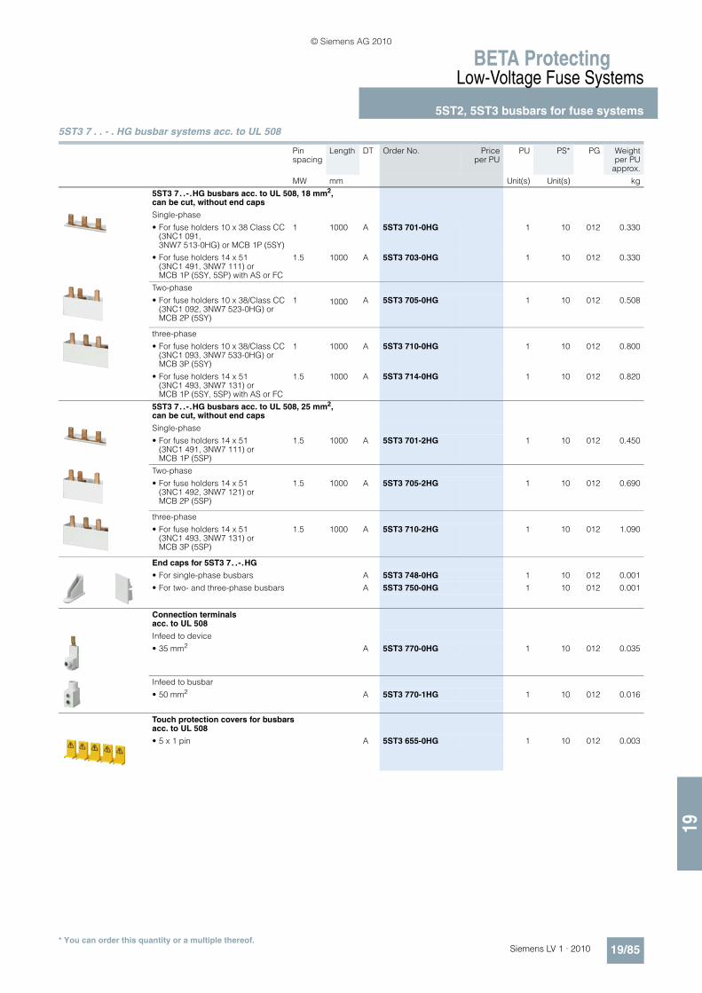
19
BETA ProtectingLow-Voltage Fuse Systems
5ST2, 5ST3 busbars for fuse systems
19/85Siemens LV 1 · 2010* You can order this quantity or a multiple thereof.
5ST3 7 . . - . HG busbar systems acc. to UL 508
Pin spacing
Length DT Order No. Priceper PU
PU PS* PG Weightper PU
approx.
MW mm Unit(s) Unit(s) kg
5ST3 7. .-.HG busbars acc. to UL 508, 18 mm2, can be cut, without end caps
Single-phase
• For fuse holders 10 x 38 Class CC (3NC1 091, 3NW7 513-0HG) or MCB 1P (5SY)
1 1000 A 5ST3 701-0HG 1 10 012 0.330
• For fuse holders 14 x 51 (3NC1 491, 3NW7 111) or MCB 1P (5SY, 5SP) with AS or FC
1.5 1000 A 5ST3 703-0HG 1 10 012 0.330
Two-phase
• For fuse holders 10 x 38/Class CC (3NC1 092, 3NW7 523-0HG) or MCB 2P (5SY)
1 1000 A 5ST3 705-0HG 1 10 012 0.508
three-phase
• For fuse holders 10 x 38/Class CC (3NC1 093, 3NW7 533-0HG) or MCB 3P (5SY)
1 1000 A 5ST3 710-0HG 1 10 012 0.800
• For fuse holders 14 x 51 (3NC1 493, 3NW7 131) or MCB 1P (5SY, 5SP) with AS or FC
1.5 1000 A 5ST3 714-0HG 1 10 012 0.820
5ST3 7. .-.HG busbars acc. to UL 508, 25 mm2, can be cut, without end caps
Single-phase
• For fuse holders 14 x 51 (3NC1 491, 3NW7 111) or MCB 1P (5SP)
1.5 1000 A 5ST3 701-2HG 1 10 012 0.450
Two-phase
• For fuse holders 14 x 51 (3NC1 492, 3NW7 121) or MCB 2P (5SP)
1.5 1000 A 5ST3 705-2HG 1 10 012 0.690
three-phase
• For fuse holders 14 x 51 (3NC1 493, 3NW7 131) or MCB 3P (5SP)
1.5 1000 A 5ST3 710-2HG 1 10 012 1.090
End caps for 5ST3 7. .-.HG
• For single-phase busbars A 5ST3 748-0HG 1 10 012 0.001
• For two- and three-phase busbars A 5ST3 750-0HG 1 10 012 0.001
Connection terminals acc. to UL 508
Infeed to device
• 35 mm2 A 5ST3 770-0HG 1 10 012 0.035
Infeed to busbar
• 50 mm2 A 5ST3 770-1HG 1 10 012 0.016
Touch protection covers for busbars acc. to UL 508
• 5 x 1 pin A 5ST3 655-0HG 1 10 012 0.003
© Siemens AG 2010

BETA ProtectingLow-Voltage Fuse Systems
3NA, 3ND LV HRC fuse links
19/86 Siemens LV 1 · 2010
19
■ Overview
LV HRC (NH type) fuse systems are used for installation systems in non-residential, commercial and industrial buildings, as well as in the systems of power supply companies. They therefore protect essential building parts and installations.
LV HRC fuse systems are fuse systems designed for operation by skilled personnel. There are no constructional requirements for non-interchangeability of rated current and touch protection.
The components and auxiliary equipment are designed in such a way as to ensure the safe replacement of LV HRC fuse systems or isolation of systems.
LV HRC fuse links are available in the sizes 000, 00, 0, 1, 2, 3, 4 and 4a.
LV HRC fuse links are available in the following operational classes:• gG for cable and line protection• aM for the short-circuit protection of switching devices in mo-
tor circuits • gR or aR for the protection of power semiconductors • gS: the new gS operational class combines cable and line
protection with semiconductor protection.
LV HRC fuse links of size 000 can also be used in LV HRC fuse bases, LV HRC fuse switch disconnectors, LV HRC fuse strips as well as in LV HRC in-line fuse switch dis-connectors of size 00.
The fuse links 300 A, 355 A and 425 A comply with the standard but do not have the VDE mark.
■ Benefits
• LV HRC fuse links with combination alarm signal the tripping of a fuse by a clear color change from red to white. This en-ables fast identification and replacement of the tripped fuse links. This increases plant availability.
• The insulated grip lugs made of metal are integrated in the top and bottom covers of the fuse link in molded plastic and pro-vide greater safety when replacing. The mark shown below in-dicates that the grip lugs are insulated .
• In the standard series with front indicator, the front-mounted red indicator signals the tripping of a fuse.
• LV HRC fuse links are always equipped with silver-plated con-tact pins. This means that they are non-corroding and have less contact resistance. This ensures the long-term opera-tional safety of the plant.
LV HRC components
$ LV HRC fuse base from the SR60 busbar system% LV HRC fuse base for busbar mounting& LV HRC fuse base, 3P( LV HRC fuse base, 1P) LV HRC contact covers* LV HRC fuse link+ LV HRC signal detectors, LV HRC partition- LV HRC protective cover
LV HRC fuse bases with slewing equipment. - for screw connection on mounting plate/ - for screw connection on busbar system 0 - for claw fixing on busbar1 LV HRC protective covers for LV HRC fuse bases with slewing
equipment2 LV HRC slewing equipment3 LV HRC fuse base cover4 LV HRC isolating link with insulated grip lugs5 LV HRC isolating link with non-insulated grip lugs6 LV HRC fuse puller with sleeve7 LV HRC fuse puller
I2_13743
1
23
45
6
15 16 17 18 19
10 11 12
14
13
9
8
7
Tripped Not tripped Tripped Not tripped
© Siemens AG 2010

19
BETA ProtectingLow-Voltage Fuse Systems
3NA, 3ND LV HRC fuse links
19/87Siemens LV 1 · 2010* You can order this quantity or a multiple thereof.
■ Selection and ordering data
Insulated grip lugs
Size Width In Un DT Order No. Priceper PU
PU PS* PG Weightper PU
approx.
mm A V AC/V DC
Unit(s) Unit(s) kg
LV HRC fuse links with combination alarm Operational class gG
000 21 10 400/-- B 3NA6 803-4 1 3 013 0.13516 B 3NA6 805-4 1 3 013 0.13520 B 3NA6 807-4 1 3 013 0.135
25 B 3NA6 810-4 1 3 013 0.13532 B 3NA6 812-4 1 3 013 0.13535 B 3NA6 814-4 1 3 013 0.135
40 B 3NA6 817-4 1 3 013 0.13550 B 3NA6 820-4 1 3 013 0.13563 B 3NA6 822-4 1 3 013 0.135
80 B 3NA6 824-4 1 3 013 0.135100 B 3NA6 830-4 1 3 013 0.135
00 30 80 400/-- B 3NA6 824-4KK 1 3 013 0.200100 B 3NA6 830-4KK 1 3 013 0.200
125 B 3NA6 832-4 1 3 013 0.200160 B 3NA6 836-4 1 3 013 0.200
1 30 35 400/-- B 3NA6 114-4 1 3 013 0.29040 B 3NA6 117-4 1 3 013 0.29050 B 3NA6 120-4 1 3 013 0.290
63 B 3NA6 122-4 1 3 013 0.29080 B 3NA6 124-4 1 3 013 0.290
100 B 3NA6 130-4 1 3 013 0.290
125 B 3NA6 132-4 1 3 013 0.290160 B 3NA6 136-4 1 3 013 0.290
47.2 200 B 3NA6 140-4 1 3 013 0.430224 B 3NA6 142-4 1 3 013 0.430250 B 3NA6 144-4 1 3 013 0.430
2 47.2 50 400/-- B 3NA6 220-4 1 3 013 0.45063 B 3NA6 222-4 1 3 013 0.45080 B 3NA6 224-4 1 3 013 0.450
100 B 3NA6 230-4 1 3 013 0.450125 B 3NA6 232-4 1 3 013 0.450160 B 3NA6 236-4 1 3 013 0.450
200 B 3NA6 240-4 1 3 013 0.450224 B 3NA6 242-4 1 3 013 0.450250 B 3NA6 244-4 1 3 013 0.450
57.8 300 B 3NA6 250-4 1 3 013 0.650315 B 3NA6 252-4 1 3 013 0.650355 B 3NA6 254-4 1 3 013 0.650400 B 3NA6 260-4 1 3 013 0.650
© Siemens AG 2010

BETA ProtectingLow-Voltage Fuse Systems
3NA, 3ND LV HRC fuse links
19/88 Siemens LV 1 · 2010
19
* You can order this quantity or a multiple thereof.
Non-insulated grip lugs
Insulated grip lugs
Size Width In Un DT Order No. Priceper PU
PG DT Order No. Priceper PU
PU PS* PG Weightper PU
approx.
A V AC/V DC
Unit(s) Unit(s) kg
LV HRC fuse links with combination alarm Operational class gG
000 21 2 500/ 250
B 3NA7 802 013 B 3NA6 802 1 3 013 0.1354 B 3NA7 804 013 B 3NA6 804 1 3 013 0.1356 B 3NA7 801 013 B 3NA6 801 1 3 013 0.135
10 B 3NA7 803 013 B 3NA6 803 1 3 013 0.13616 } 3NA7 805 013 } 3NA6 805 1 3 013 0.13620 } 3NA7 807 013 } 3NA6 807 1 3 013 0.136
25 } 3NA7 810 013 } 3NA6 810 1 3 013 0.60032 B 3NA7 812 013 B 3NA6 812 1 3 013 0.13635 } 3NA7 814 013 } 3NA6 814 1 3 013 0.440
40 B 3NA7 817 013 B 3NA6 817 1 3 013 0.13650 } 3NA7 820 013 } 3NA6 820 1 3 013 0.12863 } 3NA7 822 013 } 3NA6 822 1 3 013 0.120
80 } 3NA7 824 013 } 3NA6 824 1 3 013 0.128100 } 3NA7 830 013 } 3NA6 830 1 3 013 0.120
00 30 80 500/ 250
B 3NA7 824-7 013 B 3NA6 824-7 1 3 013 0.211100 B 3NA7 830-7 013 B 3NA6 830-7 1 3 013 0.211125 } 3NA7 832 013 } 3NA6 832 1 3 013 0.200
160 } 3NA7 836 013 A 3NA6 836 1 3 013 0.200
1 30 16 500/ 440
B 3NA7 105 013 B 3NA6 105 1 3 013 0.29020 B 3NA7 107 013 B 3NA6 107 1 3 013 0.29025 B 3NA7 110 013 B 3NA6 110 1 3 013 0.290
35 B 3NA7 114 013 B 3NA6 114 1 3 013 0.29040 B 3NA7 117 013 B 3NA6 117 1 3 013 0.29050 B 3NA7 120 013 B 3NA6 120 1 3 013 0.290
63 B 3NA7 122 013 B 3NA6 122 1 3 013 0.29080 B 3NA7 124 013 } 3NA6 124 1 3 013 0.290
100 B 3NA7 130 013 } 3NA6 130 1 3 013 0.290
125 } 3NA7 132 013 } 3NA6 132 1 3 013 0.290160 } 3NA7 136 013 } 3NA6 136 1 3 013 0.290
47.2 200 } 3NA7 140 013 } 3NA6 140 1 3 013 0.440224 B 3NA7 142 013 B 3NA6 142 1 3 013 0.440250 } 3NA7 144 013 } 3NA6 144 1 3 013 0.400
2 47.2 35 500/ 440
B 3NA7 214 013 B 3NA6 214 1 3 013 0.45050 B 3NA7 220 013 B 3NA6 220 1 3 013 0.45063 B 3NA7 222 013 B 3NA6 222 1 3 013 0.450
80 B 3NA7 224 013 B 3NA6 224 1 3 013 0.450100 B 3NA7 230 013 B 3NA6 230 1 3 013 0.450125 B 3NA7 232 013 B 3NA6 232 1 3 013 0.450
160 } 3NA7 236 013 } 3NA6 236 1 3 013 0.450200 } 3NA7 240 013 } 3NA6 240 1 3 013 0.450
224 B 3NA7 242 013 B 3NA6 242 1 3 013 0.450250 } 3NA7 244 013 } 3NA6 244 1 3 013 0.450
57.8 300 -- B 3NA6 250 1 3 013 0.641 315 } 3NA7 252 013 } 3NA6 252 1 3 013 0.660
355 -- B 3NA6 254 1 3 013 0.641400 } 3NA7 260 013 } 3NA6 260 1 3 013 0.660
© Siemens AG 2010

19
BETA ProtectingLow-Voltage Fuse Systems
3NA, 3ND LV HRC fuse links
19/89Siemens LV 1 · 2010* You can order this quantity or a multiple thereof.
Non-insulated grip lugs
Size Width In Un DT Order No. Priceper PU
PU PS* PG Weightper PU
approx.
mm A V AC/V DC
Unit(s) Unit(s) kg
LV HRC fuse links with front indicator Operational class gG
000 21 2 500/250 } 3NA3 802 1 3 013 0.1334 } 3NA3 804 1 3 013 0.1336 } 3NA3 801 1 3 013 0.133
10 } 3NA3 803 1 3 013 0.13316 } 3NA3 805 1 3 013 0.13320 } 3NA3 807 1 3 013 0.133
25 } 3NA3 810 1 3 013 0.13332 } 3NA3 812 1 3 013 0.13335 } 3NA3 814 1 3/90 013 0.133
40 } 3NA3 817 1 3 013 0.13350 } 3NA3 820 1 3/90 013 0.13363 } 3NA3 822 1 3/90 013 0.133
80 } 3NA3 824 1 3/90 013 0.133100 } 3NA3 830 1 3/90 013 0.133
125 } 3NA3 832-8 1 3/60 013 0.160160 400/250 } 3NA3 836-8 1 3/60 013 0.160
00 30 35 500/250 B 3NA3 814-7 1 3 013 0.20050 B 3NA3 820-7 1 3 013 0.20063 B 3NA3 822-7 1 3 013 0.200
80 B 3NA3 824-7 1 3 013 0.200100 B 3NA3 830-7 1 3 013 0.200125 } 3NA3 832 1 3 013 0.217
160 } 3NA3 836 1 3 013 0.217
0 30 6 500/440 B 3NA3 001 1 3 013 0.34010 B 3NA3 003 1 3 013 0.34016 B 3NA3 005 1 3 013 0.340
20 B 3NA3 007 1 3 013 0.34025 B 3NA3 010 1 3 013 0.34032 B 3NA3 012 1 3 013 0.340
35 B 3NA3 014 1 3 013 0.34040 B 3NA3 017 1 3 013 0.34050 B 3NA3 020 1 3 013 0.340
63 A 3NA3 022 1 3 013 0.34080 B 3NA3 024 1 3 013 0.340
100 A 3NA3 030 1 3 013 0.340
125 A 3NA3 032 1 3 013 0.340160 A 3NA3 036 1 3 013 0.340
1 30 16 500/440 B 3NA3 105 1 3 013 0.29020 B 3NA3 107 1 3 013 0.29025 B 3NA3 110 1 3 013 0.290
35 B 3NA3 114 1 3 013 0.30040 B 3NA3 117 1 3 013 0.30050 B 3NA3 120 1 3 013 0.300
63 } 3NA3 122 1 3 013 0.30080 } 3NA3 124 1 3 013 0.300
100 } 3NA3 130 1 3 013 0.300
125 } 3NA3 132 1 3 013 0.300160 } 3NA3 136 1 3 013 0.300
47.2 200 } 3NA3 140 1 3 013 0.440224 A 3NA3 142 1 3 013 0.440250 } 3NA3 144 1 3 013 0.440
© Siemens AG 2010

BETA ProtectingLow-Voltage Fuse Systems
3NA, 3ND LV HRC fuse links
19/90 Siemens LV 1 · 2010
19
* You can order this quantity or a multiple thereof.
Non-insulated grip lugs
Size Width In Un DT Order No. Priceper PU
PU PS* PG Weightper PU
approx.
mm A V AC/V DC
Unit(s) Unit(s) kg
LV HRC fuse links with front indicator Operational class gG
2 47.2 35 500/440 B 3NA3 214 1 3 013 0.45350 B 3NA3 220 1 3 013 0.45363 A 3NA3 222 1 3 013 0.453
80 A 3NA3 224 1 3 013 0.453100 A 3NA3 230 1 3 013 0.453125 A 3NA3 232 1 3 013 0.453
160 } 3NA3 236 1 3 013 0.453200 } 3NA3 240 1 3 013 0.453
224 } 3NA3 242 1 3 013 0.453250 } 3NA3 244 1 3 013 0.453
57.8 300 A 3NA3 250 1 3 013 0.647315 } 3NA3 252 1 3 013 0.647
355 } 3NA3 254 1 3 013 0.647400 } 3NA3 260 1 3 013 0.647
3 57.8 200 500/440 B 3NA3 340 1 3 013 0.647224 B 3NA3 342 1 3 013 0.640250 A 3NA3 344 1 3 013 0.647
300 B 3NA3 350 1 3 013 0.647315 } 3NA3 352 1 3 013 0.647
355 A 3NA3 354 1 3 013 0.647400 } 3NA3 360 1 3 013 0.647
71.2 425 A 3NA3 362 1 3 013 1.000500 } 3NA3 365 1 3 013 1.000630 } 3NA3 372 1 3 013 1.000
Can only be used with 3NH3 530 LV HRC fuse base
4 (IEC design) 101.8 630 500/440 B 3NA3 472 1 1 013 2.500800 A 3NA3 475 1 1 013 2.500
1000 A 3NA3 480 1 1 013 2.500
1250 A 3NA3 482 1 1 013 2.500
Can only be used with 3NH7 520 LV HRC fuse base
4a 101.8 500 500/440 B 3NA3 665 1 1 013 2.700630 B 3NA3 672 1 1 013 2.700800 A 3NA3 675 1 1 013 2.700
1000 A 3NA3 680 1 1 013 2.8401250 A 3NA3 682 1 1 013 2.840
© Siemens AG 2010

19
BETA ProtectingLow-Voltage Fuse Systems
3NA, 3ND LV HRC fuse links
19/91Siemens LV 1 · 2010* You can order this quantity or a multiple thereof.
Non-insulated grip lugs
Insulated grip lugs
Size- Width In Un DT Order No. Priceper PU
PG DT Order No. Priceper PU
PU PS* PG Weightper PU
approx.
A V AC/V DC
Unit(s) Unit(s) kg
LV HRC fuse links with combination alarm Operational class gG
000 21 2 690/ 250
B 3NA7 802-6 013 B 3NA6 802-6 1 3 013 0.1364 B 3NA7 804-6 013 B 3NA6 804-6 1 3 013 0.1366 B 3NA7 801-6 013 B 3NA6 801-6 1 3 013 0.136
10 B 3NA7 803-6 013 B 3NA6 803-6 1 3 013 0.13616 B 3NA7 805-6 013 B 3NA6 805-6 1 3 013 0.13620 B 3NA7 807-6 013 B 3NA6 807-6 1 3 013 0.136
25 B 3NA7 810-6 013 B 3NA6 810-6 1 3 013 0.13632 B 3NA7 812-6 013 B 3NA6 812-6 1 3 013 0.13635 B 3NA7 814-6 013 B 3NA6 814-6 1 3 013 0.136
00 30 40 690/ 250
B 3NA7 817-6 013 B 3NA6 817-6 1 3 013 0.21150 B 3NA7 820-6 013 B 3NA6 820-6 1 3 013 0.21163 B 3NA7 822-6 013 B 3NA6 822-6 1 3 013 0.211
80 B 3NA7 824-6 013 B 3NA6 824-6 1 3 013 0.211100 B 3NA7 830-6 013 B 3NA6 830-6 1 3 013 0.211
1 30 50 690/ 440
B 3NA7 120-6 013 B 3NA6 120-6 1 3 013 0.29063 B 3NA7 122-6 013 B 3NA6 122-6 1 3 013 0.29080 B 3NA7 124-6 013 B 3NA6 124-6 1 3 013 0.290
100 B 3NA7 130-6 013 B 3NA6 130-6 1 3 013 0.290125 B 3NA7 132-6 013 B 3NA6 132-6 1 3 013 0.290160 B 3NA7 136-6 013 B 3NA6 136-6 1 3 013 0.290
47.2 200 B 3NA7 140-6 013 B 3NA6 140-6 1 3 013 0.440
2 47.2 80 690/ 440
B 3NA7 224-6 013 B 3NA6 224-6 1 3 013 0.450100 B 3NA7 230-6 013 B 3NA6 230-6 1 3 013 0.450125 B 3NA7 232-6 013 B 3NA6 232-6 1 3 013 0.450
160 B 3NA7 236-6 013 B 3NA6 236-6 1 3 013 0.450200 B 3NA7 240-6 013 B 3NA6 240-6 1 3 013 0.450
57.8 224 B 3NA7 242-6 013 B 3NA6 242-6 1 3 013 0.660250 B 3NA7 244-6 013 B 3NA6 244-6 1 3 013 0.660
300 B 3NA7 250-6 013 B 3NA6 250-6 1 3 013 0.660315 B 3NA7 252-6 013 B 3NA6 252-6 1 3 013 0.660
© Siemens AG 2010

BETA ProtectingLow-Voltage Fuse Systems
3NA, 3ND LV HRC fuse links
19/92 Siemens LV 1 · 2010
19
* You can order this quantity or a multiple thereof.
Non-insulated grip lugs
Size Width In Un DT Order No. Priceper PU
PU PS* PG Weightper PU
approx.
mm A V AC/V DC
Unit(s) Unit(s) kg
LV HRC fuse links with front indicator Operational class gG
000 21 2 690/250 } 3NA3 802-6 1 3 013 0.1354 } 3NA3 804-6 1 3 013 0.1356 } 3NA3 801-6 1 3 013 0.135
10 } 3NA3 803-6 1 3 013 0.13516 } 3NA3 805-6 1 3 013 0.13520 } 3NA3 807-6 1 3 013 0.135
25 } 3NA3 810-6 1 3 013 0.13532 B 3NA3 812-6 1 3 013 0.13535 } 3NA3 814-6 1 3 013 0.135
00 30 40 690/250 B 3NA3 817-6 1 3 013 0.20050 } 3NA3 820-6 1 3 013 0.20063 } 3NA3 822-6 1 3 013 0.200
80 } 3NA3 824-6 1 3 013 0.200100 } 3NA3 830-6 1 3 013 0.200
1 30 50 690/440 B 3NA3 120-6 1 3 013 0.29063 B 3NA3 122-6 1 3 013 0.29080 B 3NA3 124-6 1 3 013 0.290
100 } 3NA3 130-6 1 3 013 0.290125 } 3NA3 132-6 1 3 013 0.290160 } 3NA3 136-6 1 3 013 0.290
47.2 200 } 3NA3 140-6 1 3 013 0.426
2 47.2 80 690/440 B 3NA3 224-6 1 3 013 0.426100 B 3NA3 230-6 1 3 013 0.426125 B 3NA3 232-6 1 3 013 0.426
160 } 3NA3 236-6 1 3 013 0.426200 } 3NA3 240-6 1 3 013 0.426
57.8 224 B 3NA3 242-6 1 3 013 0.660250 } 3NA3 244-6 1 3 013 0.680
300 B 3NA3 250-6 1 3 013 0.660315 } 3NA3 252-6 1 3 013 0.680
3 57.8 250 690/440 B 3NA3 344-6 1 3 013 0.660315 B 3NA3 352-6 1 3 013 0.660
71.2 355 B 3NA3 354-6 1 3 013 1.000400 } 3NA3 360-6 1 3 013 1.000
425 B 3NA3 362-6 1 3 013 1.000500 } 3NA3 365-6 1 3 013 1.000
© Siemens AG 2010

19
BETA ProtectingLow-Voltage Fuse Systems
3NA, 3ND LV HRC fuse links
19/93Siemens LV 1 · 2010* You can order this quantity or a multiple thereof.
Non-insulated grip lugs
Size Width In Un DT Order No. Priceper PU
PU PS* PG Weightper PU
approx.
mm A V AC/V DC
Unit(s) Unit(s) kg
LV HRC fuse links with front indicator Operational class aM
000 21 6 500/-- B 3ND1 801 1 3 014 0.13010 B 3ND1 803 1 3 014 0.13016 B 3ND1 805 1 3 014 0.130
20 B 3ND1 807 1 3 014 0.13025 B 3ND1 810 1 3 014 0.13032 B 3ND1 812 1 3 014 0.130
35 B 3ND1 814 1 3 014 0.13040 B 3ND1 817 1 3 014 0.13050 B 3ND1 820 1 3 014 0.130
63 B 3ND1 822 1 3 014 0.13080 B 3ND1 824 1 3 014 0.130
00 30 100 500/-- B 3ND1 830 1 3 014 0.192125 B 3ND1 832 1 3 014 0.192160 B 3ND1 836 1 3 014 0.192
1 30 63 690/-- B 3ND2 122 1 3 014 0.29080 B 3ND2 124 1 3 014 0.290
100 B 3ND2 130 1 3 014 0.440
47.2 125 B 3ND2 132 1 3 014 0.440160 B 3ND2 136 1 3 014 0.440
200 B 3ND2 140 1 3 014 0.440250 B 3ND2 144 1 3 014 0.440
2 47.2 125 690/-- B 3ND2 232 1 3 014 0.440160 B 3ND2 236 1 3 014 0.440
200 B 3ND2 240 1 3 014 0.440250 B 3ND2 244 1 3 014 0.440
57.8 315 B 3ND2 252 1 3 014 0.650355 B 3ND2 254 1 3 014 0.650400 A 3ND2 260 1 3 014 0.650
3 57.8 315 690/-- B 3ND2 352 1 3 014 0.650355 B 3ND2 354 1 3 014 0.650400 B 3ND2 360 1 3 014 0.650
71.2 500 B 3ND1 365 1 3 014 1.030630 B 3ND1 372 1 3 014 1.000
© Siemens AG 2010
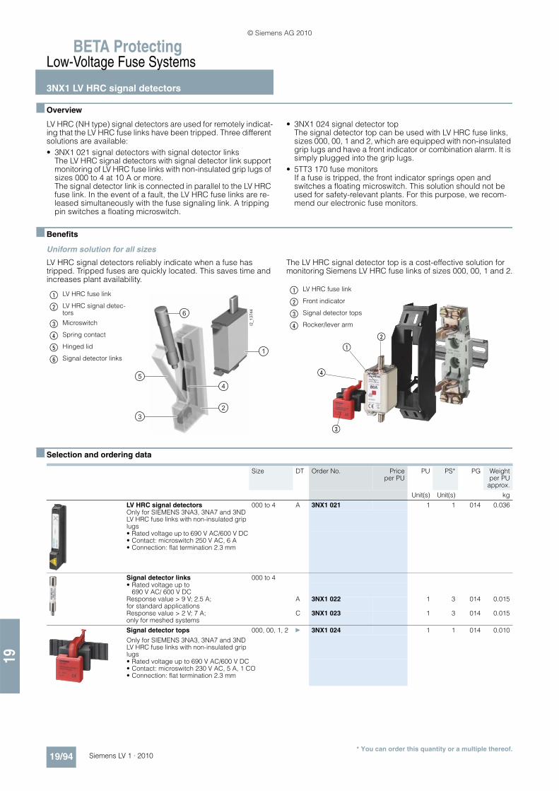
BETA ProtectingLow-Voltage Fuse Systems
3NX1 LV HRC signal detectors
19/94 Siemens LV 1 · 2010
19
* You can order this quantity or a multiple thereof.
■ Overview
LV HRC (NH type) signal detectors are used for remotely indicat-ing that the LV HRC fuse links have been tripped. Three different solutions are available:• 3NX1 021 signal detectors with signal detector links
The LV HRC signal detectors with signal detector link support monitoring of LV HRC fuse links with non-insulated grip lugs of sizes 000 to 4 at 10 A or more. The signal detector link is connected in parallel to the LV HRC fuse link. In the event of a fault, the LV HRC fuse links are re-leased simultaneously with the fuse signaling link. A tripping pin switches a floating microswitch.
• 3NX1 024 signal detector topThe signal detector top can be used with LV HRC fuse links, sizes 000, 00, 1 and 2, which are equipped with non-insulated grip lugs and have a front indicator or combination alarm. It is simply plugged into the grip lugs.
• 5TT3 170 fuse monitorsIf a fuse is tripped, the front indicator springs open and switches a floating microswitch. This solution should not be used for safety-relevant plants. For this purpose, we recom-mend our electronic fuse monitors.
■ Benefits
Uniform solution for all sizes
LV HRC signal detectors reliably indicate when a fuse has tripped. Tripped fuses are quickly located. This saves time and increases plant availability.
The LV HRC signal detector top is a cost-effective solution for monitoring Siemens LV HRC fuse links of sizes 000, 00, 1 and 2.
■ Selection and ordering data
$ LV HRC fuse link
% LV HRC signal detec-tors
& Microswitch
( Spring contact
) Hinged lid
* Signal detector links
I2_1
3744
1
6
5
3
4
2
$ LV HRC fuse link
% Front indicator
& Signal detector tops
( Rocker/lever arm
$
%
&
(
Size DT Order No. Priceper PU
PU PS* PG Weightper PU
approx.
Unit(s) Unit(s) kg
LV HRC signal detectors 000 to 4 A 3NX1 021 1 1 014 0.036Only for SIEMENS 3NA3, 3NA7 and 3ND LV HRC fuse links with non-insulated grip lugs• Rated voltage up to 690 V AC/600 V DC• Contact: microswitch 250 V AC, 6 A• Connection: flat termination 2.3 mm
Signal detector links 000 to 4• Rated voltage up to
690 V AC/ 600 V DCResponse value > 9 V; 2.5 A; for standard applications
A 3NX1 022 1 3 014 0.015
Response value > 2 V; 7 A; only for meshed systems
C 3NX1 023 1 3 014 0.015
Signal detector tops 000, 00, 1, 2 } 3NX1 024 1 1 014 0.010
Only for SIEMENS 3NA3, 3NA7 and 3ND LV HRC fuse links with non-insulated grip lugs• Rated voltage up to 690 V AC/600 V DC• Contact: microswitch 230 V AC, 5 A, 1 CO• Connection: flat termination 2.3 mm
© Siemens AG 2010

19
BETA ProtectingLow-Voltage Fuse Systems
3NX1 LV HRC signal detectors3NH LV HRC fuse bases
19/95Siemens LV 1 · 2010* You can order this quantity or a multiple thereof.
3NX1 LV HRC signal detectors
For more information on fuse monitors, please refer to Chapter "Monitoring of electrical values" in Catalog ET B1.
■ Overview
3NH LV HRC fuse bases
Terminals for all applications
Terminals are as different as the requirements of individual sys-tems.
Flat terminals with screws are suitable for connecting busbars or cable lugs. They have a torsion-proof screw connection with shim, spring washer and nut. When tightening the nut, always ensure compliance with the specified torque due to the consid-erable leverage effect.The double busbar terminal differs from the flat terminal in that it supports connection of two busbars, one on the top and one at the bottom of the flat terminal.
The modern box terminal ensures efficient and reliable connec-tion to the conductors. They support connection of conductors with or without end sleeves.
In the case of flat terminals with nuts, connection of the nut to the terminal lug is torsion-proof. When tightening the nut, the torque must be observed because of the considerable leverage effect.
Up to three conductors can be clamped to the terminal strip.
Ue In Uc MW DT Order No. Priceper PU
PU PS* PG Weightper PU
approx.
V AC A V Unit(s) Unit(s) kg
Fuse monitors
For all low-voltage fuse systems.Can be used in asymmetric systems afflicted with harmonics and regenerative feedback motors. Signal also for disconnected loads.
230 4 3 AC 380 ... 415 2 } 5TT3 170 1 1 027 0.150
© Siemens AG 2010

BETA ProtectingLow-Voltage Fuse Systems
3NH LV HRC fuse bases
19/96 Siemens LV 1 · 2010
19
The plug-in terminal is equipped for connecting two conductors.
One conductor can be clamped to the saddle-type terminal.
■ Benefits
• The silver-plated lyre-shaped contact provides a large con-tact area for the contact pin of the LV HRC fuse link. This im-proves heat transmission and lowers the temperature. It also minimizes aging of the fuse link in the maximum load range, in particular when using SITOR fuses
• The large contact area also facilitates replacement of LV HRC fuse links
• The spring washer that tensions the contact is mechanically galvanized. This will prevent hydrogen embrittlement. The contact is resistant to aging and there will be no dreaded an-nealing of contacts, which considerably improves operating safety.
© Siemens AG 2010

19
BETA ProtectingLow-Voltage Fuse Systems
3NH LV HRC fuse bases
19/97Siemens LV 1 · 2010* You can order this quantity or a multiple thereof.
■ Selection and ordering data
Size In Version DT Order No. Priceper PU
PU PS* PG Weightper PU
approx.
A Unit(s) Unit(s) kg
LV HRC fuse bases
Made of molded plastic, for standard rail mounting or screw fixing
000/00 1P160 With flat terminals, screw } 3NH3 051 1 1/10 014 0.119
With saddle-type terminals } 3NH3 052 1 1/10 014 0.114
125 With box terminals, up to 50 mm2 } 3NH3 053 1 1/10 014 0.109
Made of ceramic for screw fixing
000/00 160 1PWith flat terminals, screw } 3NH3 030 1 3 014 0.235With plug-in terminals B 3NH3 031 1 3 014 0.230With saddle-type terminals } 3NH3 032 1 3 014 0.266
With flat terminals and terminal strip B 3NH3 035 1 3 014 0.230With flat terminals, nut B 3NH3 038 1 3 014 0.207With flat and saddle-type terminals B 3NH3 050 1 3 014 0.227
3P (incl. two partitions)With flat terminals } 3NH4 030 1 1 014 0.700With plug-in terminals B 3NH4 031 1 1 014 0.800With saddle-type terminals B 3NH4 032 1 1 014 0.800With flat terminals and terminal strip B 3NH4 035 1 1 014 0.750
Made of ceramic for screw fixing
0 160 1PWith flat terminals A 3NH3 120 1 3 014 0.460With plug-in terminals B 3NH3 122 1 3 014 0.460
Made of ceramic for screw fixing
1 250 1PWith flat terminals } 3NH3 230 1 3 014 0.789With double busbar terminals B 3NH3 220 1 3 014 0.789
Ceramic support on base plate for screw fixing
1 250 3P (incl. two partitions)With flat terminals A 3NH4 230 1 1 014 2.100
Made of ceramic for screw fixing
2 400 1PWith flat terminals } 3NH3 330 1 1 014 0.843With double busbar terminals A 3NH3 320 1 1 014 1.000
Made of ceramic for screw fixing
3 630 1PWith flat terminals } 3NH3 430 1 1 014 1.100With double busbar terminals A 3NH3 420 1 1 014 1.100
© Siemens AG 2010

BETA ProtectingLow-Voltage Fuse Systems
3NH LV HRC fuse bases
19/98 Siemens LV 1 · 2010
19
* You can order this quantity or a multiple thereof.
Size In Version DT Order No. Priceper PU
PU PS* PG Weightper PU
approx.
A Unit(s) Unit(s) kg
LV HRC fuse bases
Ceramic support on base plate for screw fixing (IEC design)
4 1250 1PWith flat terminals A 3NH3 530 1 1 014 3.000
LV HRC bus-mounting bases made of molded plasticFor busbars 12 mm × 5 mm to 12 mm × 10 mm, busbar spacing 40 mm
000/00 160 1PWith saddle-type terminals at top B 3NH3 036 1 1 014 0.150With saddle-type terminals at bottom B 3NH3 037 1 1 014 0.150
000/00 80 3P, in tandem design3 outgoing feeders at top and bottom respec-tively, with saddle-type terminal
With 4 partitions B 3NH4 037 1 1 014 0.800With 2 non-interrupted partitions B 3NH4 045 1 1 014 0.800
LV HRC fuse bases with slewing equipmentWith flat terminals and additional saddle-type terminals (included)
000/00 160 1P
With screw fixing for mounting plate A 3NH7 030 1 1 014 1.000With claw fixing for non-perforated busbar
B 3NH7 031 1 1 014 1.000
With screw fixing for perforated busbar
B 3NH7 032 1 1 014 1.000
1 250 1P
With screw fixing for mounting plate A 3NH7 230 1 1 014 2.500With claw fixing for non-perforated busbar
B 3NH7 231 1 1 014 2.500
With screw fixing for perforated busbar
B 3NH7 232 1 1 014 2.500
Can also be used for fuse links of size 2
3 630 1P
With screw fixing for mounting plate B 3NH7 330 1 1 014 4.800With claw fixing for non-perforated busbar
B 3NH7 331 1 1 014 4.800
With screw fixing for perforated busbar, can be used as disconnector
B 3NH7 332 1 1 014 4.800
© Siemens AG 2010

19
BETA ProtectingLow-Voltage Fuse Systems
3NH LV HRC fuse bases
19/99Siemens LV 1 · 2010* You can order this quantity or a multiple thereof.
Size In Version DT Order No. Priceper PU
PU PS* PG Weightper PU
approx.
A Unit(s) Unit(s) kg
LV HRC fuse bases with slewing equipment
4a 1250 1P
With screw fixing for mounting plate
A 3NH7 520 1 1 014 5.200
LV HRC contact covers for LV HRC fuse bases
Touch protection for contact pieces
000/00 } 3NX3 105 1 2/20 014 0.0130 B 3NX3 114 1 2/40 014 0.0101 } 3NX3 106 1 2/20 014 0.027
2 } 3NX3 107 1 2/12 014 0.0313 } 3NX3 108 1 2/10 014 0.038
LV HRC partitions for LV HRC fuse bases
As intermediate phase and end barrier
000/00 Type
3NH3 0/3NH4 0 } 3NX2 023 1 2 014 0.0250 3NH3 1 B 3NX2 030 1 2 014 0.0501 3NH3 2 } 3NX2 024 1 2 014 0.053
2 3NH3 3 } 3NX2 025 1 2 014 0.0663 3NH3 4 } 3NX2 026 1 2 014 0.101
LV HRC protective covers IP2X
For LV HRC fuse bases
000/00 1P and 3P B 3NX3 115 1 10 014 0.039
LV HRC covers
000/00 For plugging into IP2X LV HRC protective covers
B 3NX3 116 1 10 014 0.014
LV HRC contact covers for LV HRC bus-mounting bases
000/00 Touch protection for contact pieces
Outgoing terminal } 3NX3 105 1 2/20 014 0.013Incoming terminal B 3NX3 113 1 2/50 014 0.006
LV HRC partitions for 3NH3 0 LV HRC bus-mounting bases
000/00 As intermediate partition C 3NX2 027 1 2 014 0.017
000/00 As end barrier C 3NX2 028 1 2/50 014 0.020
© Siemens AG 2010

BETA ProtectingLow-Voltage Fuse Systems
3NH LV HRC fuse bases
19/100 Siemens LV 1 · 2010
19
* You can order this quantity or a multiple thereof.
Size Version DT Order No. Priceper PU
PU PS* PG Weightper PU
approx.
Unit(s) Unit(s) kg
Non-interrupted partitions
000/00 For 3NH4 0 LV HRC bus-mounting bases C 3NX2 031 1 2/30 014 0.050
Fuse-base covers, for LV HRC fuse bases, red
With inscription "isolating point"
000/00 C 3NX1 003 1 3 014 0.0501, 2, 3 C 3NX1 004 1 3 014 0.100
Fuse pullers
000 to 4 For LV HRC fuse links
Without sleeve } 3NX1 013 1 1 014 0.280
With sleeve } 3NX1 014 1 1 014 0.480
Isolating links for LV HRC fuse bases and fuse switch disconnectors
With insulated grip lugs
000/00 Silver-plated } 3NG1 002 1 3/30 014 0.0800 C 3NG1 102 1 1/10 014 0.110
1 } 3NG1 202 1 1/10 014 0.1702 } 3NG1 302 1 1/5 014 0.2403 } 3NG1 402 1 1/5 014 0.290
With non-insulated grip lugs
4 Tinned B 3NG1 503 1 6 014 0.7084a Nickel-plated B 3NG1 505 1 1/5 014 0.730
© Siemens AG 2010

19
BETA ProtectingSITOR Semiconductor Fuses
SITOR, LV HRC design
19/101Siemens LV 1 · 2010
■ Overview
SITOR fuses protect power semiconductors from the effects of a short circuit because the super-quick disconnect characteristic is far quicker than that of conventional LV HRC (NH type) fuse systems. They protect expensive devices and system compo-nents such as converters with fuses in the input and in the DC link, UPS systems and soft starters for motors.
Panel mounting requirements have given rise to various connec-tion versions and designs.
The fuses with blade contacts comply with IEC 60269-2 and are suitable for installation in LV HRC fuse bases, in LV HRC fuse switch disconnectors and in switch disconnectors with fuses. They also include fuses with slotted blade contacts for screw fix-ing with 110 mm mounting dimension, whose sizes comply with IEC 60269-4.
Fuses with slotted blade contacts for screw fixing with 80 mm or 110 mm mounting dimension are often screwed directly onto busbars for optimum heat dissipation. Even better heat transmis-sion is provided by the compact fuses with M10 or M12 female thread, which are also mounted directly onto busbars.
Bolt-on links with 80 mm mounting dimension are another panel-mounting version for direct busbar mounting.
The fuses for SITOR thyristor sets, railway rectifiers or electroly-sis systems were developed specially for these applications.
To find out which LV HRC fuse bases and safety switching de-vices can be used with the SITOR fuses, please refer to the chapter "Low-voltage fuse systems".
Fuse characteristic curves, configuration notes and the assign-ment of SITOR fuses to 3NP and 3KL fuse bases and safety switching devices can be found in catalog ET B1 Add-On Fuse Characteristic Curves and Configuration Notes and on the Inter-net.
The new type ranges for size 3 have a round rather than square ceramic body. These series are characterized by small I²t values with low power dissipation and high capability under alternating load. The dimensions and functional dimensions correspond to the current standards IEC 60269-4/EN 60269-4 (VDE 0636-4).
Note:The ordering data of the fuses are listed in ascending order of the rated voltage in the selection tables.
■ Benefits
• SITOR fuses have a high varying load factor, which ensures a high level of operational reliability and plant availability - even when subject to constant load change.
• The use of SITOR fuses in LV HRC fuse bases or Siemens switch disconnectors has been tested with regard to heat dis-sipation and maximum current loading. This makes planning and dimensioning easier and prevents consequential dam-age.
• Our high standard of quality ensures good compliance with the characteristic curve and accuracy. This ensures long-term protection of devices.
Operational classes
Fuses are categorized according to function and operational classes. SITOR semiconductor fuses, in LV HRC design, are available in the following operational classes:• aR: for the short-circuit protection of power semiconductors
(partial range protection)• gR: for the protection of power semiconductors
(full range protection)• gS: The gS operational class combines cable and line protec-
tion with semiconductor protection (full range protection).
© Siemens AG 2010

BETA ProtectingSITOR Semiconductor Fuses
SITOR, LV HRC design
19/102 Siemens LV 1 · 2010
19
* You can order this quantity or a multiple thereof.
■ Selection and ordering data
Size Ie Ue Opera-tional class
Breaking I2t value
Power loss
Vary-ing load factor
DT Order No. Priceper PU
PU PS* PG Weightper PU
approx.
A V AC A2s W WL Unit(s) Unit(s) kg
SITOR, LV HRC design
With slotted blade contacts for M10 screw fixing, mounting dimension: 110 mm, or for installation in LV HRC fuse bases or fuse switch disconnectors
3 150 500 gR 33000 35 0.85 B 3NC2 423-3C 1 3 047 0.940200 64000 40 0.85 B 3NC2 425-3C 1 3 047 0.940250 99000 50 0.85 B 3NC2 427-3C 1 3 047 0.940
300 132000 65 0.85 B 3NC2 428-3C 1 3 047 0.940350 aR 249000 60 0.85 B 3NC2 431-3C 1 3 047 0.940400 390000 50 0.85 B 3NC2 432-3C 1 3 047 0.940
With slotted blade contacts with two M10 oblong slots, or for installation in LV HRC fuse bases or fuse switch discon-nectors
3 150 500 gR 33000 35 0.85 D 3NC2 423-0C 1 3 047 0.940200 64000 40 0.85 D 3NC2 425-0C 1 3 047 0.940250 99000 50 0.85 D 3NC2 427-0C 1 3 047 0.940
300 132000 65 0.85 D 3NC2 428-0C 1 3 047 0.940350 aR 249000 60 0.85 C 3NC2 431-0C 1 3 047 0.940400 390000 50 0.85 D 3NC2 432-0C 1 3 047 0.940
With blade contacts for mounting in LV HRC fuse bases or switch disconnectors
3 710 600 gR 2460000 65 1.0 D 3NE1 437-1 1 3 047 1.120800 3350000 72 1.0 B 3NE1 438-1 1 3 047 1.113
With slotted blade contacts for M10 screw fixing, mounting dimension: 110 mm, or for installation in LV HRC fuse bases or fuse switch disconnectors
3 150 690 gR 17600 40 0.85 B 3NC8 423-3C 1 3 047 0.940200 38400 55 0.85 B 3NC8 425-3C 1 3 047 0.940250 70400 72 0.85 B 3NC8 427-3C 1 3 047 0.940
350 176000 95 0.85 B 3NC8 431-3C 1 3 047 0.940500 448000 130 0.85 B 3NC8 434-3C 1 3 047 0.940
1000 600 aR 2480000 140 0.9 C 3NC8 444-3C 1 3 047 0.940
With slotted blade contacts for M10 screw fixing, mounting dimension: 110 mm, or for installation in LV HRC fuse bases or fuse switch disconnectors
1 160 690 gR 18600 30 1.0 B 3NE1 224-3 1 3 047 0.610200 51800 28 1.0 B 3NE1 225-3 1 3 047 0.610250 80900 35 1.0 B 3NE1 227-3 1 3 047 0.610315 168000 42 1.0 B 3NE1 230-3 1 3 047 0.610
With slotted blade contacts for M10 screw fixing, mounting dimension: 110 mm, or for installation in LV HRC fuse bases or fuse switch disconnectors
2 350 690 gR 177000 44 1.0 B 3NE1 331-3 1 3 047 0.750400 224000 54 1.0 B 3NE1 332-3 1 3 047 0.750450 276500 62 1.0 B 3NE1 333-3 1 3 047 0.750500 398000 65 1.0 B 3NE1 334-3 1 3 047 0.750
© Siemens AG 2010

19
BETA ProtectingSITOR Semiconductor Fuses
SITOR, LV HRC design
19/103Siemens LV 1 · 2010* You can order this quantity or a multiple thereof.
1) DC voltages according to UL.
Size Ie Ue Opera-tional class
Breaking I2t value
Power loss
Vary-ing load factor
DT Order No. Priceper PU
PU PS* PG Weightper PU
approx.
A V AC A2s W WL Unit(s) Unit(s) kg
SITOR, LV HRC design
With slotted blade contacts for M12 screw fixing, mounting dimension: 110 mm, or for installation in LV HRC fuse bases or fuse switch disconnectors
3 560 690 gR 890000 60 1.0 B 3NE1 435-3 1 3 047 1.150630 1390000 62 1.0 B 3NE1 436-3 1 3 047 1.150670 1640000 65 1.0 B 3NE1 447-3 1 3 047 1.150
710 1818000 72 1.0 B 3NE1 437-3 1 3 047 1.150800 2475000 82 1.0 B 3NE1 438-3 1 3 047 1.150850 3640000 76 1.0 B 3NE1 448-3 1 3 047 1.150
With slotted blade contacts with two oblong slots for M10 screw fixing, or for installation in LV HRC fuse bases or switch disconnectors
3 150 690 gR 17600 40 0.85 B 3NC8 423-0C 1 3 047 0.940200 38400 55 0.85 B 3NC8 425-0C 1 3 047 0.940250 70400 72 0.85 B 3NC8 427-0C 1 3 047 0.940
350 176000 95 0.85 B 3NC8 431-0C 1 3 047 0.940500 448000 130 0.85 B 3NC8 434-0C 1 3 047 0.940
Size Ie Ue Opera-tional class
Breaking I2t value
Power loss
Vary-ing load factor
DT Order No. Priceper PU
PU PS* PG Weightper PU
approx.
A V AC/V DC
A2s W WL Unit(s) Unit(s) kg
SITOR, LV HRC design
With M8 bolt-on links, mounting dimension: 80 mm, for screwing onto busbars
000 20 690/ 7001)
gR 83 7 0.9 B 3NE8 714-1 1 10 047 0.130
25 140 9 0.9 B 3NE8 715-1 1 10 047 0.13032 285 10 0.9 A 3NE8 701-1 1 10 047 0.131
40 490 12 0.9 A 3NE8 702-1 1 10 047 0.13150 815 15 0.9 A 3NE8 717-1 1 10 047 0.13263 aR 1550 16 0.95 A 3NE8 718-1 1 10 047 0.132
80 2700 18 0.9 } 3NE8 720-1 1 10 047 0.131100 4950 19 0.95 } 3NE8 721-1 1 10 047 0.130125 9100 23 0.95 } 3NE8 722-1 1 10 047 0.131
160 17000 31 0.9 } 3NE8 724-1 1 10 047 0.132200 30000 36 0.9 } 3NE8 725-1 1 10 047 0.130250 55000 42 0.9 } 3NE8 727-1 1 10 047 0.133
315 85500 54 0.85 } 3NE8 731-1 1 10 047 0.134
© Siemens AG 2010
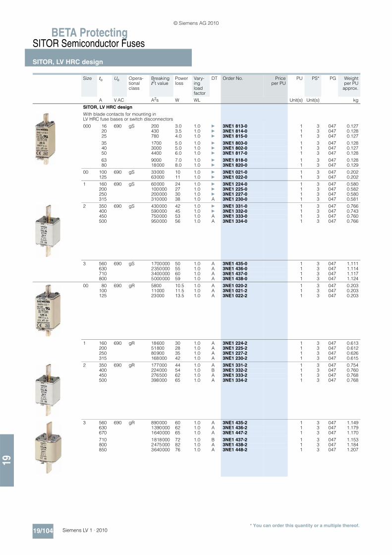
BETA ProtectingSITOR Semiconductor Fuses
SITOR, LV HRC design
19/104 Siemens LV 1 · 2010
19
* You can order this quantity or a multiple thereof.
Size Ie Ue Opera-tional class
Breaking I2t value
Power loss
Vary-ing load factor
DT Order No. Priceper PU
PU PS* PG Weightper PU
approx.
A V AC A2s W WL Unit(s) Unit(s) kg
SITOR, LV HRC design
With blade contacts for mounting in LV HRC fuse bases or switch disconnectors
000 16 690 gS 200 3.0 1.0 } 3NE1 813-0 1 3 047 0.12720 430 3.5 1.0 } 3NE1 814-0 1 3 047 0.12825 780 4.0 1.0 } 3NE1 815-0 1 3 047 0.127
35 1700 5.0 1.0 } 3NE1 803-0 1 3 047 0.12840 3000 5.0 1.0 } 3NE1 802-0 1 3 047 0.12750 4400 6.0 1.0 } 3NE1 817-0 1 3 047 0.128
63 9000 7.0 1.0 } 3NE1 818-0 1 3 047 0.12880 18000 8.0 1.0 } 3NE1 820-0 1 3 047 0.129
00 100 690 gS 33000 10 1.0 } 3NE1 021-0 1 3 047 0.202125 63000 11 1.0 } 3NE1 022-0 1 3 047 0.202
1 160 690 gS 60000 24 1.0 } 3NE1 224-0 1 3 047 0.580200 100000 27 1.0 } 3NE1 225-0 1 3 047 0.582250 200000 30 1.0 } 3NE1 227-0 1 3 047 0.580315 310000 38 1.0 A 3NE1 230-0 1 3 047 0.581
2 350 690 gS 430000 42 1.0 } 3NE1 331-0 1 3 047 0.766400 590000 45 1.0 } 3NE1 332-0 1 3 047 0.743450 750000 53 1.0 A 3NE1 333-0 1 3 047 0.760500 950000 56 1.0 A 3NE1 334-0 1 3 047 0.766
3 560 690 gS 1700000 50 1.0 A 3NE1 435-0 1 3 047 1.111630 2350000 55 1.0 A 3NE1 436-0 1 3 047 1.114710 3400000 60 1.0 A 3NE1 437-0 1 3 047 1.117800 5000000 59 1.0 A 3NE1 438-0 1 3 047 1.124
00 80 690 gR 5800 10.5 1.0 A 3NE1 020-2 1 3 047 0.203100 11000 11.5 1.0 A 3NE1 021-2 1 3 047 0.203125 23000 13.5 1.0 A 3NE1 022-2 1 3 047 0.203
1 160 690 gR 18600 30 1.0 A 3NE1 224-2 1 3 047 0.613200 51800 28 1.0 A 3NE1 225-2 1 3 047 0.612250 80900 35 1.0 A 3NE1 227-2 1 3 047 0.626315 168000 42 1.0 A 3NE1 230-2 1 3 047 0.615
2 350 690 gR 177000 44 1.0 A 3NE1 331-2 1 3 047 0.754400 224000 54 1.0 B 3NE1 332-2 1 3 047 0.760450 276500 62 1.0 A 3NE1 333-2 1 3 047 0.768500 398000 65 1.0 A 3NE1 334-2 1 3 047 0.768
3 560 690 gR 890000 60 1.0 A 3NE1 435-2 1 3 047 1.149630 1390000 62 1.0 A 3NE1 436-2 1 3 047 1.179670 1640000 65 1.0 A 3NE1 447-2 1 3 047 1.170
710 1818000 72 1.0 B 3NE1 437-2 1 3 047 1.153800 2475000 82 1.0 A 3NE1 438-2 1 3 047 1.184850 3640000 76 1.0 A 3NE1 448-2 1 3 047 1.207
© Siemens AG 2010

19
BETA ProtectingSITOR Semiconductor Fuses
SITOR, LV HRC design
19/105Siemens LV 1 · 2010* You can order this quantity or a multiple thereof.
Size Ie Ue Opera-tional class
Breaking I2t value
Power loss
Vary-ing load factor
DT Order No. Priceper PU
PU PS* PG Weightper PU
approx.
A V AC A2s W WL Unit(s) Unit(s) kg
SITOR, LV HRC design
With blade contacts for mounting in LV HRC fuse bases or fuse switch disconnectors (contd.)
00 25 690 gR 180 7 0.95 } 3NE8 015-1 1 3 047 0.20535 400 9 0.95 } 3NE8 003-1 1 3 047 0.20450 700 14 0.95 } 3NE8 017-1 1 3 047 0.203
63 1400 16 0.95 } 3NE8 018-1 1 3 047 0.20580 aR 2400 19 0.95 } 3NE8 020-1 1 3 047 0.203
100 4200 22 0.95 } 3NE8 021-1 1 3 047 0.205
125 6500 28 0.95 } 3NE8 022-1 1 3 047 0.213160 13000 38 0.95 } 3NE8 024-1 1 3 047 0.207
With slotted blade contacts for M12 screw fixing, mounting dimension: 80 mm
3 630 690 aR 244000 120 0.85 C 3NC3 236-1 1 3 047 0.785710 346000 130 0.85 D 3NC3 237-1 1 3 047 0.785800 498000 135 0.9 C 3NC3 238-1 1 3 047 0.785900 677000 145 0.9 D 3NC3 240-1 1 3 047 0.785
1000 975000 155 0.95 C 3NC3 241-1 1 3 047 0.7851100 1382000 165 0.95 D 3NC3 242-1 1 3 047 0.7851250 1990000 175 0.95 C 3NC3 243-1 1 3 047 0.785
1400 500 2100000 200 0.95 D 3NC3 244-1 1 3 047 0.7851600 2860000 240 0.9 D 3NC3 245-1 1 3 047 0.785
With M12 female thread at both ends for direct busbar mounting
3 630 690 aR 244000 125 0.9 C 3NC3 236-6 1 3 047 0.765710 346000 130 0.9 D 3NC3 237-6 1 3 047 0.765800 498000 135 0.95 C 3NC3 238-6 1 3 047 0.765900 677000 140 0.95 D 3NC3 240-6 1 3 047 0.765
1000 975000 145 1.0 C 3NC3 241-6 1 3 047 0.7651100 1382000 150 1.0 D 3NC3 242-6 1 3 047 0.7651250 1990000 155 1.0 C 3NC3 243-6 1 3 047 0.765
1400 500 2100000 175 1.0 C 3NC3 244-6 1 3 047 0.7651600 2860000 195 0.95 C 3NC3 245-6 1 3 047 0.765
With slotted blade contacts for M10 screw fixing,mounting dimension: 110 mm, or for installation in LV HRC fuse bases or fuse switch disconnectors
2 250 800 aR 29700 105 0.85 } 3NE4 327-0B 1 3 047 0.753315 60700 120 0.85 } 3NE4 330-0B 1 3 047 0.760450 191000 140 0.85 } 3NE4 333-0B 1 3 047 0.760
500 276000 155 0.85 } 3NE4 334-0B 1 3 047 0.754710 923000 155 0.85 } 3NE4 337 1 3 047 0.771
With blade contacts for mounting in LV HRC fuse bases or switch disconnectors
0 32 1000 gR 280 12 0.9 } 3NE4 101 1 3 047 0.27840 500 13 0.9 } 3NE4 102 1 3 047 0.27750 800 16 0.9 } 3NE4 117 1 3 047 0.276
63 aR 1500 20 0.9 } 3NE4 118 1 3 047 0.27980 3000 22 0.9 } 3NE4 120 1 3 047 0.276
100 6000 24 0.9 } 3NE4 121 1 3 047 0.278
125 14000 30 0.9 } 3NE4 122 1 3 047 0.279160 29000 35 0.9 } 3NE4 124 1 3 047 0.279
© Siemens AG 2010

BETA ProtectingSITOR Semiconductor Fuses
SITOR, LV HRC design
19/106 Siemens LV 1 · 2010
19
* You can order this quantity or a multiple thereof.
Size Ie Ue Opera-tional class
Breaking I2t value
Power loss
Vary-ing load factor
DT Order No. Priceper PU
PU PS* PG Weightper PU
approx.
A V AC A2s W WL Unit(s) Unit(s) kg
SITOR, LV HRC design
With slotted blade contacts for M10 screw fixing, mounting dimension: 110 mm, or for installation in LV HRC fuse bases or fuse switch disconnectors
1 100 1000 aR 4800 28 0.95 A 3NE3 221 1 3 047 0.580125 7200 36 0.95 A 3NE3 222 1 3 047 0.568160 13000 42 0.95 } 3NE3 224 1 3 047 0.573
200 30000 42 0.95 } 3NE3 225 1 3 047 0.570250 48000 50 0.95 } 3NE3 227 1 3 047 0.580315 80000 65 0.95 } 3NE3 230-0B 1 3 047 0.585
350 100000 75 0.9 A 3NE3 231 1 3 047 0.590400 135000 85 0.9 A 3NE3 232-0B 1 3 047 0.576450 175000 95 0.9 } 3NE3 233 1 3 047 0.720
2 400 1000 aR 135000 85 1.0 A 3NE3 332-0B 1 3 047 0.759450 175000 90 1.0 A 3NE3 333 1 3 047 0.748500 260000 90 1.0 } 3NE3 334-0B 1 3 047 0.753
560 360000 95 1.0 } 3NE3 335 1 3 047 0.756630 600000 100 1.0 } 3NE3 336 1 3 047 0.760
710 900 aR 800000 105 1.0 } 3NE3 337-8 1 3 047 0.762800 800 850000 130 0.95 } 3NE3 338-8 1 3 047 0.764900 690 920000 165 0.95 } 3NE3 340-8 1 3 047 0.753
With slotted blade contacts for M10 screw fixing, mounting dimension: 130 mm
3 100 1000 aR 13500 25 1.0 D 3NE3 421-0C 1 3 047 1.120224 54000 85 1.0 B 3NE3 626-0C 1 3 047 1.120315 218000 80 1.0 B 3NE3 430-0C 1 3 047 1.120
400 364000 110 1.0 B 3NE3 432-0C 1 3 047 1.120450 488000 110 1.0 B 3NE3 635-0C 1 3 047 1.120
500 870000 95 1.0 B 3NE3 434-0C 1 3 047 1.120630 1280000 132 1.0 D 3NE3 636-0C 1 3 047 1.120710 1950000 145 1.0 D 3NE3 637-0C 1 3 047 1.120
With M10 female thread at both ends for direct mounting on busbars
3 450 1000 aR 488000 110 1.0 D 3NE3 635-6 1 3 047 1.184
With slotted blade contacts for M12 screw fixing, mounting dimension: 140 mm
3 710 1000 aR 1950000 145 1.0 D 3NE3 637-1C 1 3 047 1.120
With slotted blade contacts for M12 screw fixing, mounting dimension: 110 mm, or for installation in LV HRC fuse bases or fuse switch disconnectors
3 630 1000 aR 418000 145 0.85 C 3NC3 336-1 1 3 047 1.020710 569000 150 0.85 D 3NC3 337-1 1 3 047 1.020800 819000 155 0.85 C 3NC3 338-1 1 3 047 1.020900 1160000 165 0.9 D 3NC3 340-1 1 3 047 1.0201000 1670000 170 0.9 C 3NC3 341-1 1 3 047 1.020
1100 800 1910000 185 0.9 D 3NC3 342-1 1 3 047 1.0201250 2600000 210 0.9 D 3NC3 343-1 1 3 047 1.020
© Siemens AG 2010

19
BETA ProtectingSITOR Semiconductor Fuses
SITOR, LV HRC design
19/107Siemens LV 1 · 2010* You can order this quantity or a multiple thereof.
Size Ie Ue Opera-tional class
Breaking I2t value
Power loss
Vary-ing load factor
DT Order No. Priceper PU
PU PS* PG Weightper PU
approx.
A V AC A2s W WL Unit(s) Unit(s) kg
SITOR, LV HRC design
With M12 female thread at both ends for direct busbar mounting
3 630 1000 aR 418000 130 0.90 C 3NC3 336-6 1 3 047 0.980710 569000 140 0.90 D 3NC3 337-6 1 3 047 0.980800 819000 150 0.90 C 3NC3 338-6 1 3 047 0.980900 1160000 160 0.95 D 3NC3 340-6 1 3 047 0.9801000 1670000 165 0.95 C 3NC3 341-6 1 3 047 0.980
1100 800 1910000 175 0.95 D 3NC3 342-6 1 3 047 0.9801250 2600000 185 0.95 C 3NC3 343-6 1 3 047 0.980
With slotted blade contacts for M12 screw fixing, mounting dimension: 110 mm
3 315 1250 aR 72500 80 0.95 B 3NC3 430-1 1 3 047 0.950400 163000 95 0.95 B 3NC3 432-1 1 3 047 0.950500 290000 115 0.90 B 3NC3 434-1 1 3 047 0.950630 650000 120 0.95 B 3NC3 436-1 1 3 047 0.950
800 1100 985000 145 0.90 B 3NC3 438-1 1 3 047 1.150
With M12 female thread at both ends for direct busbar mounting
3 315 1250 aR 72500 80 0.95 B 3NC3 430-6 1 3 047 0.910400 163000 95 0.95 B 3NC3 432-6 1 3 047 0.910500 290000 115 0.90 B 3NC3 434-6 1 3 047 0.910630 650000 120 0.95 B 3NC3 436-6 1 3 047 0.910
800 1100 985000 145 0.95 B 3NC3 438-6 1 3 047 1.110
With slotted blade contacts for M10 screw fixing, mounting dimension: 210 mm
3 160 1500 aR 54000 56 1.0 D 3NE5 424-0C 1 2 047 1.860224 138000 80 1.0 C 3NE5 426-0C 1 2 047 1.860315 311000 115 1.0 D 3NE5 430-0C 1 2 047 1.860
350 428000 135 1.0 D 3NE5 431-0C 1 2 047 1.860450 870000 145 0.95 D 3NE5 433-0C 1 2 047 1.860450 870000 145 0.95 D 3NE5 433-1C 1 2 047 1.860
With slotted blade contacts for M10 screw fixing, mounting dimension: 170 mm
3 250 1500 aR 84000 130 1.0 D 3NE5 627-0C 1 3 047 1.520450 590000 160 1.0 B 3NE5 633-0C 1 3 047 1.520600 1950000 145 1.0 D 3NE5 643-0C 1 3 047 1.520
With slotted blade contacts for M10 screw fixing, mounting dimension: 210 mm
3 200 2000 aR 138000 75 1.0 D 3NE7 425-0C 1 2 047 1.860250 218000 110 1.0 D 3NE7 427-0C 1 2 047 1.860350 555000 120 1.0 D 3NE7 431-0C 1 2 047 1.860400 870000 150 1.0 D 3NE7 432-0C 1 2 047 1.860
450 960000 160 1.0 D 3NE7 633-0C 1 2 047 1.860630 1950000 220 1.0 D 3NE7 636-0C 1 2 047 1.860
With slotted blade contacts for M12 screw fixing, mounting dimension: 210 mm
3 450 2000 aR 960000 160 1.0 C 3NE7 633-1C 1 2 047 1.860525 1120000 210 1.0 D 3NE7 648-1C 1 2 047 1.860630 1950000 220 1.0 C 3NE7 636-1C 1 1 047 1.860710 3110000 275 1.0 B 3NE7 637-1C 1 2 047 1.860
© Siemens AG 2010

BETA ProtectingSITOR Semiconductor Fuses
SITOR, LV HRC design
19/108 Siemens LV 1 · 2010
19
* You can order this quantity or a multiple thereof.
1) Special design.
Size Ie Ue Opera-tional class
Breaking I2t value
Power loss
Vary-ing load factor
DT Order No. Priceper PU
PU PS* PG Weightper PU
approx.
A V AC A2s W WL Unit(s) Unit(s) kg
SITOR, LV HRC design
With slotted blade contacts for M12 screw fixing, mounting dimension: 260 mm
3 400 2500 aR 620,000 250 1.0 D 3NE9 632-1C 1 1 047 2.350500 1,270,000 235 1.0 D 3NE9 634-1C 1 1 047 2.350630 2,800,000 275 1.0 D 3NE9 636-1C 1 1 047 2.350
Fuses for special applications
For screwing onto water-cooled busbars, for rectifiers in electrolysis systems
--1) 350 800 aR 260,000 80 0.9 X 3NC5 531 1 3 047 0.671600 1000 888,000 150 0.9 D 3NC5 840 1 3 047 1.408630 800 888,000 145 0.9 C 3NC5 841 1 3 047 1.185800 1000 1,728,000 170 0.9 D 3NC5 838 1 3 047 1.196
710 900 620,000 150 0.9 D 3NE6 437-7 1 3 047 1.1681250 600 2,480,000 210 0.9 D 3NE9 450-7 1 3 047 1.245
With M10 female thread at both ends for direct busbar mounting, for air-cooled rectifiers in electrolysis systems
--1) 710 900 gR 620,000 150 0.9 D 3NE6 437 1 3 047 1.093850 600 2,480,000 85 1.0 D 3NE9 440-6 1 3 047 1.082900 900 aR 1,920,000 170 0.9 C 3NE6 444 1 3 047 1.175
1250 600 2,480,000 210 0.9 D 3NE9 450 1 3 047 1.114
Fuse with installation holder for SITOR 6QG10 thyristor sets
-- 200 1000 aR 44,000 50 0.85 D 3NE3 525-5 1 2 047 0.744450 395,000 90 0.85 D 3NE3 535-5 1 2 047 0.746
Fuse with installation holder for SITOR 6QG11 thyristor sets
--1) 50 1000 gR 1,100 20 0.85 C 3NE4 117-5 1 2 047 0.303100 aR 7,400 35 0.85 B 3NE4 121-5 1 2 047 0.309170 aR 60,500 43 0.85 B 3NE4 146-5 1 2 047 0.311
Fuse female thread at both ends for SITOR 6QG12 thyristor sets
--1) 250 800 aR 29,700 105 0.85 } 3NE4 327-6B 1 3 047 0.692315 60,700 120 0.85 } 3NE4 330-6B 1 3 047 0.688450 191,000 140 0.85 } 3NE4 333-6B 1 3 047 0.690
500 276,000 155 0.85 } 3NE4 334-6B 1 3 047 0.688710 923,000 155 0.95 } 3NE4 337-6 1 3 047 0.689
With M12 female thread at both ends for direct busbar mounting for railway supply rectifiers
--1) 250 680 aR 635,000 25 0.9 D 3NC7 327-2 1 3 047 0.725350 1,430,000 32 0.9 D 3NC7 331-2 1 3 047 0.740
© Siemens AG 2010

19
BETA ProtectingSITOR Semiconductor Fuses
SITOR, cylindrical fuse design
19/109Siemens LV 1 · 2010* You can order this quantity or a multiple thereof.
■ Overview
SITOR cylindrical fuses protect power semiconductors against the effects of short circuits because the super quick disconnect characteristic is far quicker than that of conventional fuses. They protect expensive devices and system components such as solid-state contactors, electronic relays (solid state), converters with fuses in the input and in the DC link, UPS systems and soft starters for motors up to 100 A.
The cylindrical design is approved for industrial applications. The cylindrical fuse links comply with IEC 60269.
Cylindrical fuse holders also comply with IEC 60269 and UL 512. The cylindrical fuse holders for 10 x 38 mm and 14 x 51 mm have been tested and approved as fuse switch dis-connectors and the cylindrical fuse holders for 22 x 58 mm as fuse disconnectors according to the switching device standard IEC 60947-3. The utilization category and the tested current and voltage values are specified in the Table "Technical Specifica-tions".
The cylindrical fuse holders have been specially developed for the application of SITOR fuse links with regard to heat tolerance and heat dissipation and are therefore not recommended for standard applications.
Cylindrical fuse bases do not offer the same comprehensive touch protection as the fuse holders, but have better heat dissi-pation. The single-pole cylindrical fuse bases for 14 × 51 mm and 22 × 58 mm allow modular expansion to multipole bases.
■ Benefits
• Cylindrical fuses have an extremely compact design and a correspondingly small footprint
• The cylindrical fuses have IEC and UL approval and are suit-able for universal use worldwide.
• The use of SITOR cylindrical fuses in the cylindrical fuse hold-ers and bases has been tested with regard to heat dissipation and maximum current loading. This makes planning and di-mensioning easier and prevents consequential damage.
• The use of fuse holders as switch disconnectors expands the area of application of these devices and increases operating safety.
■ Selection and ordering data
1) DC voltages according to UL.
Size Ie Ue Breaking I2t value
Power loss
DT Order No. Priceper PU
PU PS* PG Weightper PU
approx.
mm × mm A V AC/V DC
A2s W Unit(s) Unit(s) kg
Cylindrical fuse links, operational class aR
10 × 38 3 600/400 8 1.2 A 3NC1 003 1 10 047 0.0096 20 1.5 } 3NC1 006 1 10 047 0.0098 30 2 B 3NC1 008 1 10 047 0.009
10 60 2.5 } 3NC1 010 1 10 047 0.00912 110 3 B 3NC1 012 1 10 047 0.00916 150 3.5 } 3NC1 016 1 10 047 0.009
20 200 4.8 } 3NC1 020 1 10 047 0.00925 250 6 } 3NC1 025 1 10 047 0.00932 500 7.5 } 3NC1 032 1 10 047 0.009
14 × 51 1 660/7001) 1.2 5 B 3NC1 401 1 10 047 0.0202 10 3 } 3NC1 402 1 10 047 0.0203 15 2.5 B 3NC1 403 1 10 047 0.0204 25 3 } 3NC1 404 1 10 047 0.020
5 690/7001) 9 1.5 B 3NC1 405 1 10 047 0.0206 12 1.5 } 3NC1 406 1 10 047 0.020
10 20 4 } 3NC1 410 1 10 047 0.02015 75 5.5 } 3NC1 415 1 10 047 0.02020 120 6 } 3NC1 420 1 10 047 0.020
25 250 7 } 3NC1 425 1 10 047 0.02030 300 9 B 3NC1 430 1 10 047 0.02032 700 7.6 } 3NC1 432 1 10 047 0.021
40 900 8 } 3NC1 440 1 10 047 0.02150 1800 9 } 3NC1 450 1 10 047 0.021
22 × 58 20 690/7001) 220 4.6 B 3NC2 220 1 5 047 0.05625 300 5.6 B 3NC2 225 1 5 047 0.05632 450 7 B 3NC2 232 1 5 047 0.056
40 700 8.5 B 3NC2 240 1 5 047 0.05650 1350 9.5 } 3NC2 250 1 5 047 0.056
63 2600 11 } 3NC2 263 1 5 047 0.05680 5500 13.5 } 3NC2 280 1 5 047 0.057
100 600/7001) 8000 16 } 3NC2 200 1 5 047 0.05750 1500 9.5 B 3NC2 250-5 1 5 047 0.056
63 3000 11 B 3NC2 263-5 1 5 047 0.05680 6000 13.5 B 3NC2 280-5 1 5 047 0.057
22 × 58 100 600/7001) 8500 16 B 3NC2 200-5 1 5 047 0.057
© Siemens AG 2010

BETA ProtectingSITOR Semiconductor Fuses
SITOR, cylindrical fuse design
19/110 Siemens LV 1 · 2010
19
* You can order this quantity or a multiple thereof.
1) DC voltages according to UL.
1) Please observe the utilization category and current / voltage values speci-fied in the "Technical specifications" table.
Size Ie Ue Breaking I2t value
Power loss
DT Order No. Priceper PU
PU PS* PG Weightper PU
approx.
mm × mm A V AC/V DC
A2s W Unit(s) Unit(s) kg
Cylindrical fuse links with striking pin, operational class aR
14 × 51 10 690/7001) 90 4 B 3NC1 410-5 1 10 047 0.02015 100 5.5 B 3NC1 415-5 1 10 047 0.02020 500 6 B 3NC1 420-5 1 10 047 0.020
25 400 7 C 3NC1 425-5 1 10 047 0.02030 500 9 C 3NC1 430-5 1 10 047 0.02032 600 7.6 B 3NC1 432-5 1 10 047 0.020
40 900 8 B 3NC1 440-5 1 10 047 0.02050 2000 9 B 3NC1 450-5 1 10 047 0.020
22 × 58 20 690/7001) 240 5 C 3NC2 220-5 1 10 047 0.05625 350 6 C 3NC2 225-5 1 5 047 0.05632 500 8 B 3NC2 232-5 1 5 047 0.056
40 800 9 B 3NC2 240-5 1 5 047 0.056
Size Version Rated voltage DT Order No. Priceper PU
PU PS* PG Weightper PU
approx.
mm × mm V AC Unit(s) Unit(s) kg
Cylindrical fuse holders Can be used as fuse switch disconnectors/discon.1)
10 × 38 1P 690 } 3NC1 091 1 12 047 0.0652P } 3NC1 092 1 6 047 0.1313P } 3NC1 093 1 4 047 0.197
14 × 51 1P } 3NC1 491 1 6 047 0.1252P } 3NC1 492 1 3 047 0.2333P B 3NC1 493 1 2 047 0.350
22 × 58 1P } 3NC2 291 1 1 047 0.1932P } 3NC2 292 1 3 047 0.3813P B 3NC2 293 1 2 047 0.584
Cylindrical fuse holders Can be used as fuse switch disconnectors, with signal-ing switches for fuse links with striking pin1)
14 × 51 1P 690 B 3NC1 491-5 1 6 047 0.12522 × 58 1P B 3NC2 291-5 1 6 047 0.193
Cylindrical fuse bases
10 × 38 1P 600 B 3NC1 038-1 1 10 047 0.0422P C 3NC1 038-2 1 8 047 0.0773P B 3NC1 038-3 1 6 047 0.113
14 × 51 1P 690 B 3NC1 451-1 1 3 047 0.12022 × 58 1P B 3NC2 258-1 1 3 047 0.238
Cylindrical fuse clips
For fuses 10 × 38 C 3NC1 038 1 20 047 0.002For fuses 14 × 51 B 3NC1 451 1 20 047 0.005
Fuse tongs
10 × 38,14 × 51,22 × 58
B 3NC1 000 1 1 047 0.069
© Siemens AG 2010
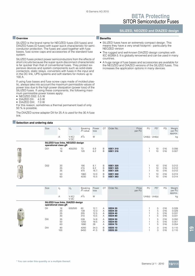
19
BETA ProtectingSITOR Semiconductor Fuses
SILIZED, NEOZED and DIAZED design
19/111Siemens LV 1 · 2010* You can order this quantity or a multiple thereof.
■ Overview
SILIZED is the brand name for NEOZED fuses (D0 fuses) and DIAZED fuses (D fuses) with super quick characteristic for semi-conductor protection. The fuses are used together with fuse bases, fuse screw caps and accessories of the standard fuse system.
SILIZED fuses protect power semiconductors from the effects of short circuits because the super quick disconnect characteristic is far quicker than that of conventional fuses. They protect ex-pensive devices and system components such as solid-state contactors, static relays, converters with fuses in the input and in the DC link, UPS systems and soft starters for motors up to 100 A.
If using fuse bases and fuse screw caps made of molded plas-tic, always take into account the maximum permissible values of power loss due to the high power dissipation (power loss) of the SILIZED fuses. If using these components, the following maxi-mum permissible power losses apply: • NEOZED D02: 5.5 W• DIAZED DII: 4.5 W• DIAZED DIII: 7.0 WFor this reason, sometimes a thermal permanent load of only 50 % is possible.
The DIAZED screw adapter DII for 25 A is used for the 30 A fuse link.
■ Benefits
• SILIZED fuses have an extremely compact design. This means they have a very small footprint - particularly the NEOZED version
• The rugged and well-known DIAZED design complies with IEC 60269-3. It is globally renowned and can be used in many countries.
• A huge range of fuse bases and accessories are available for the NEOZED and DIAZED versions of the SILIZED fuses. This increases the application options in many devices.
■ Selection and ordering data
Size Ie Ue Breaking I2t value
Power loss
DT Order No. Priceper PU
PU PS* PG Weightper PU
approx.
A V AC/V DC
A2s W Unit(s) Unit(s) kg
SILIZED fuse links, NEOZED designoperational class gR
D01 10 400/250 73 6.9 B 5SE1 310 1 10 016 0.00616 120 6.2 B 5SE1 316 1 10 016 0.007
D02 20 190 8.1 B 5SE1 320 1 10 016 0.01225 215 8.2 B 5SE1 325 1 10 016 0.01235 470 16.7 B 5SE1 335 1 10 016 0.012
50 1960 12.0 B 5SE1 350 1 10 016 0.01363 4230 15.5 B 5SE1 363 1 10 016 0.014
Size Ie Ue Breaking I2t value
Power loss
DT Order No. Priceper PU
PU PS* PG Weightper PU
approx.
A V AC/V DC
A2s W Unit(s) Unit(s) kg
SILIZED fuse links, DIAZED designoperational class gR
DII 16 500/500 60 12.1 A 5SD4 20 1 5 016 0.02820 139 12.3 A 5SD4 30 1 5 016 0.02925 205 12.5 A 5SD4 40 1 5 016 0.03130 310 13.5 A 5SD4 80 1 5 016 0.031
DIII 35 539 14.8 A 5SD4 50 1 5 016 0.05050 1250 18.5 A 5SD4 60 1 5 016 0.05163 1890 28 A 5SD4 70 1 5 016 0.054
DIV 80 4200 34.3 B 5SD5 10 1 3 016 0.110100 8450 41.5 B 5SD5 20 1 3 016 0.110
© Siemens AG 2010

BETA ProtectingSR60 Busbar Systems
Distribution board components
19/112 Siemens LV 1 · 2010
19
■ Overview
The use of busbar systems with their versatile rail-adaptable connection, switching and installation devices is an ideal and cost-effective electrotechnical enhancement of modern distribu-
tion boards due to their small footprint, compact design and quick assembly contacts. Mounting is implemented on longitu-dinal stays. The busbar spacing is 60 mm.
■ Benefits
• Only a few distribution board components are required to en-sure the integration of busbars in the distribution board. This saves time and space.
• The touch protection cover is sealable as standard and is quick and easy to attach to the supports thanks to the use of quick-release locking technology.
I201
_136
33
87
9
56
3
3
4
2
1
$ Longitudinal stays% Busbar supports, three-phase& Cu busbars( Terminals) Supports for blanking covers* Blanking covers+ Supports, Touch protection covers- Busbar supports, single-phase
© Siemens AG 2010

19
BETA ProtectingSR60 Busbar Systems
Distribution board components
19/113Siemens LV 1 · 2010* You can order this quantity or a multiple thereof.
■ Selection and ordering data
Dimensions DT Order No. Priceper PU
PU PS* PG Weightper PU
approx.
mm Unit(s) Unit(s) kg
Longitudinal stays
For mounting the assembly kits in unequipped dis-tribution boards, two longitudinal stays are required1 set = 2 stays
Height
600 A 8GK4 851-4KK00 1 set 1 set 039 1.000750 A 8GK4 851-5KK00 1 set 1 set 039 1.300900 A 8GK4 851-6KK00 1 set 1 set 039 1.500
1050 A 8GK4 851-7KK00 1 set 1 set 039 1.8001200 A 8GK4 851-8KK00 1 set 1 set 039 2.0801350 A 8GK4 852-8KK00 1 set 1 set 039 2.340
Busbar supportsFor busbars with a thickness of 5 or 10 mm and a busbar height of 12, 15, 20, 25 or 30 mm, for mounting on longitudinal stays, with fixing screws
three-phase A 8GK9 711-0KK03 1 1 039 1.100
N/PE busbar supports
For flat copper profiles For 5/10 mm busbars
A 5SH3 540 1 1 016 0.059
Cu busbars
Cu cross-section Length
12 × 5 mm, current intensity 250 A
250 A 8GK9 731-0KK10 1 5 039 0.100500 A 8GK9 731-0KK20 1 5 039 0.330750 A 8GK9 731-0KK30 1 5 039 0.500
1000 A 8GK9 731-0KK40 1 5 039 0.6601250 A 8GK9 731-0KK50 1 5 039 0.830
20 × 5 mm, current intensity 320 A
250 A 8GK9 733-0KK10 1 5 039 0.290500 A 8GK9 733-0KK20 1 5 039 0.570750 A 8GK9 733-0KK30 1 5 039 0.850
1000 A 8GK9 733-0KK40 1 5 039 1.1201250 A 8GK9 733-0KK50 1 5 039 1.470
30 × 5 mm, current intensity 450 A
250 A 8GK9 735-0KK10 1 5 039 0.400500 A 8GK9 735-0KK20 1 5 039 0.750750 A 8GK9 735-0KK30 1 5 039 1.460
1000 A 8GK9 735-0KK40 1 5 039 2.1701250 A 8GK9 735-0KK50 1 5 039 2.880
30 × 10 mm, current intensity 630 A
250 A 8GK9 736-0KK10 1 5 039 0.750500 A 8GK9 736-0KK20 1 5 039 1.720750 A 8GK9 736-0KK30 1 5 039 2.600
1000 A 8GK9 736-0KK40 1 5 039 3.4001250 A 8GK9 736-0KK50 1 5 039 4.600
Cover profiles for busbars
Busbar thickness 5 mm
Width 12 mm 1000 A 8US19 22-2CA00 1 10 143 0.200Width 15, 20, 25, 30 mm 1000 A 8US19 22-2AA00 1 10 143 0.156
Busbar thickness 10 mm
Width 12, 15, 20, 25, 30 mm 1000 A 8US19 22-2BA00 1 10 143 0.105
© Siemens AG 2010
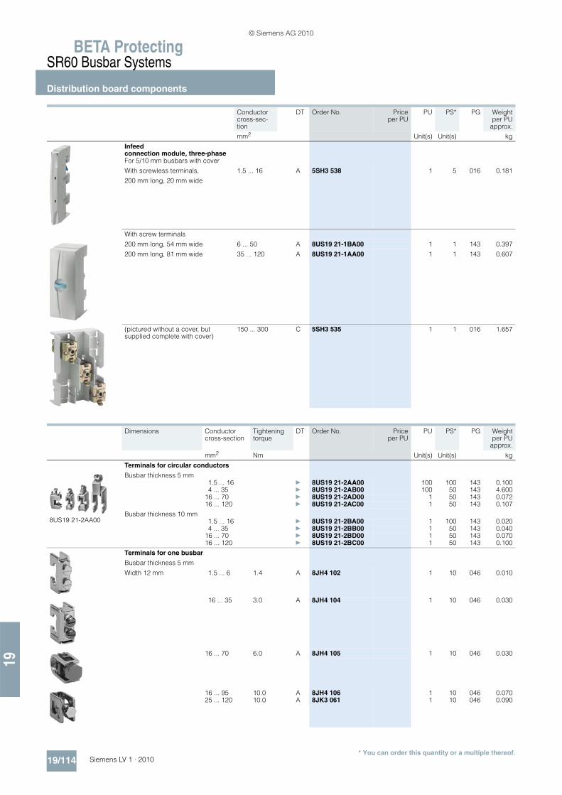
BETA ProtectingSR60 Busbar Systems
Distribution board components
19/114 Siemens LV 1 · 2010
19
* You can order this quantity or a multiple thereof.
Conductor cross-sec-tion
DT Order No. Priceper PU
PU PS* PG Weightper PU
approx.
mm2 Unit(s) Unit(s) kg
Infeed connection module, three-phase For 5/10 mm busbars with cover
With screwless terminals,
200 mm long, 20 mm wide
1.5 ... 16 A 5SH3 538 1 5 016 0.181
With screw terminals
200 mm long, 54 mm wide 6 ... 50 A 8US19 21-1BA00 1 1 143 0.397
200 mm long, 81 mm wide 35 ... 120 A 8US19 21-1AA00 1 1 143 0.607
(pictured without a cover, but supplied complete with cover)
150 ... 300 C 5SH3 535 1 1 016 1.657
Dimensions Conductor cross-section
Tightening torque
DT Order No. Priceper PU
PU PS* PG Weightper PU
approx.
mm2 Nm Unit(s) Unit(s) kg
Terminals for circular conductors
8US19 21-2AA00
Busbar thickness 5 mm1.5 ... 16 } 8US19 21-2AA00 100 100 143 0.1004 ... 35 } 8US19 21-2AB00 100 50 143 4.600
16 ... 70 } 8US19 21-2AD00 1 50 143 0.07216 ... 120 } 8US19 21-2AC00 1 50 143 0.107
Busbar thickness 10 mm1.5 ... 16 } 8US19 21-2BA00 1 100 143 0.0204 ... 35 } 8US19 21-2BB00 1 50 143 0.040
16 ... 70 } 8US19 21-2BD00 1 50 143 0.07016 ... 120 } 8US19 21-2BC00 1 50 143 0.100
Terminals for one busbar
Busbar thickness 5 mm
Width 12 mm 1.5 ... 6 1.4 A 8JH4 102 1 10 046 0.010
16 ... 35 3.0 A 8JH4 104 1 10 046 0.030
16 ... 70 6.0 A 8JH4 105 1 10 046 0.030
16 ... 95 10.0 A 8JH4 106 1 10 046 0.07025 ... 120 10.0 A 8JK3 061 1 10 046 0.090
© Siemens AG 2010

19
BETA ProtectingSR60 Busbar Systems
Distribution board components
19/115Siemens LV 1 · 2010* You can order this quantity or a multiple thereof.
■ More information
Number of built-in components that can be mounted
More information about the SR60 distribution board components of the busbar system can be found in Catalog ET B1 · 2010.
The current issue of the catalog can be downloaded from www.siemens.com/e-installation-catalogs.
Dimensions Conductor cross-section
Tightening torque
DT Order No. Priceper PU
PU PS* PG Weightper PU
approx.
mm2 Nm Unit(s) Unit(s) kg
Extension terminals
For busbars 12 mm × 5 mm(busbar not included in scope of supply)(1 set = 2 units) 6.0 A 8JK3 201 1 set 10 sets 046 0.100
Terminals for circular conductors
20 mm × 5 mm to 30 mm × 10 mm 150 ... 240 A 8US19 41-2BB00 1 6 143 0.307
Connection modules
For 32 mm cover level with box terminal 6 ... 70 mm2
A 3NP1 933-1BC00 1 1 143 0.145
Dimensions(H x W)
DT Order No. Priceper PU
PU PS* PG Weightper PU
approx.
mm × mm Unit(s) Unit(s) kg
Assembly kits
Comprising touch protection cover and 4 supports
Cutout width
For three-phase busbar systems
216 mm 300 × 250 A 8GK4 801-2KK13 1 1 039 0.500466 mm 300 × 500 A 8GK4 801-2KK23 1 1 039 0.700716 mm 300 × 750 A 8GK4 801-2KK33 1 1 039 0.900
216 mm 450 × 250 A 8GK4 801-3KK13 1 1 039 0.650466 mm 450 × 500 A 8GK4 801-3KK23 1 1 039 0.900716 mm 450 × 750 A 8GK4 801-3KK33 1 1 039 1.150
Support for blanking cover
For blanking covermounting on busbar(2 units required for each section of blanking cover
B 5SH3 536 1 4/160 016 0.040
Blanking cover
Mounting on 5SH3 536 support for blanking covers
Length Height1000 mm 202 mm A 5SH3 537 1 2 016 0.075
Height Width Cut-out width D02/63 A 5SH5 241
D02/63 A 5SH5 242
D02/63 A 5SH5 243
DII/25 A 5SH2 042
DIII/63 A 5SH2 242
5SG7 230 bus-mounting switch disconnectors D02
mm mm mm (27 mm wide) (36 mm wide) (54 mm wide) (42 mm wide) (57 mm wide) (26.8 mm wide)
300 250 216 8 6 4 5 3 8500 466 17 12 8 11 8 17
750 716 26 19 13 17 12 26
450 250 216 8 6 4 5 3 8500 466 17 12 8 11 8 17
750 715 26 19 13 17 12 26
© Siemens AG 2010

BETA ProtectingSR60 Busbar Systems
Built-in components
19/116 Siemens LV 1 · 2010
19
■ Overview
Rail-adaptable built-in components, such as NEOZED and DIAZED bus-mounting bases, adapters for modular installation devices, LV HRC fuse switch disconnectors and NEOZED bus-mounting fuse switch disconnectors are made of glass-fiber re-inforced, thermoplastic polyester. The material ensures required mechanical, chemical and electrical properties.
Efficient power distribution up to 630 A. There are many ways for users to mount the SR60 busbar sys-tem:
1. Mounting in the distribution board
The busbar supports are mounted on longitudinal stays. Once the built-in components have been mounted and connected, the touch protection cover (front cover) protects against accidental contact with live parts.
2. Mounting in control cabinets
The demand for comprehensive touch protection has generated new solutions: Built-in components, such as bus-mounting fuse bases, have integrated rear reach-through guard, thus enabling the configuration of cost-effective overall solutions.
The two previously available optional solutions can now be re-placed with new technology: the touch protection over base and the respective edges, or touch protection by means of partitions.
Overall, increased efficiency and cost savings for the plant man-ufacturer.
The fuse holders for cylindrical fuses, size 10 × 38 and for Amer-ican fuses, Class CC, can be used in the international plant en-gineering industry. In addition, Siemens offers a wide range of UL-approved components for the design of switchgear assem-blies in accordance with UL 508 A. For further information, see chapter BETA devices approved to UL standard in Catalog LV 16 · 2009.
Fuse holders are available with a connection module 16 mm² and screwless terminals; this offers users maximum safety and comfort.
■ Benefits
• The direct contact of the rail-adaptable switching and installa-tion devices on the Cu busbars reduces distribution panels and mounting times, and
• The transfer resistance of the connections are drastically re-duced, when compared to conventional installation. This pre-vents unnecessary temperature rises.
• New touch-protected built-in components ensure comprehen-sive touch protection without the previously required partitions
• International implementation due to UL-approved compo-nents
• Enhanced effectiveness and increased safety due to screw-less terminals.
I2_1
3634
a
4
5
3
6
7
2
1
$ NEOZED bus-mounting bases, 3-pole% DIAZED bus-mounting bases, 3-pole& SR60 bus-mounting fuse holders, 3-pole( NEOZED bus-mounting switch disconnectors, 3-pole) Connection modules, three-phase* Adapter for modular installation devices according to DIN 43880+ LV HRC fuse switch disconnectors
© Siemens AG 2010

19
BETA ProtectingSR60 Busbar Systems
Built-in components
19/117Siemens LV 1 · 2010* You can order this quantity or a multiple thereof.
■ Selection and ordering data
For NEOZED screw caps, adapter sleeves and fuse links, see Catalog ET B1 · 2010, Chapter, "Low-voltage fuse systems, NEOZED fuse systems". You can download the up-to-date catalog from www.siemens.com/e-installation-catalogs.
Size Rated current Rated voltage MW DT Order No. Priceper PU
PU PS* PG Weightper PU
approx.
A V Unit(s) Unit(s) kg
NEOZED SR60 bus-mounting bases with touch protection, 3PFor 5/10 mm busbars
27 mm wide
D02 63 400 1.5 B 5SG6 206 1 4 016 0.175
36 mm wide
D02 63 400 2 B 5SG6 207 1 4 016 0.188
NEOZED SR60 bus-mounting bases, 3P, standard versionFor 5/10 mm busbars
D02 63 400 1.5 A 5SG6 202 1 4/104 016 0.141
NEOZED SR60 covers for standard version
D02 1.5 A 5SH5 241 1 4/200 016 0.026Extra wide, with clearance for wiring
D02 2 B 5SH5 242 1 4/140 016 0.031
With double width for more clearance for wiring
D02 3 C 5SH5 243 1 4/120 016 0.040
DIAZED SR60 bus-mounting bases with touch protection, 3PFor 5/10 mm busbars
For use of DIAZED SR60 adapter ringsDII 25 500 2.3 B 5SF6 018 1 4 016 0.301DIII 63 500 V AC/DC (acc. to
DIN VDE 0636-3 also 690 V AC/600 V DC)
3.2 B 5SF6 218 1 4 016 0.402
For use of DIAZED screw adaptersDII 25 500 2.3 B 5SF6 020 1 4 016 0.291DIII 63 500 V AC/DC (acc. to
DIN VDE 0636-3 also 690 V AC/600 V DC)
3.2 B 5SF6 220 1 4 016 0.392
© Siemens AG 2010

BETA ProtectingSR60 Busbar Systems
Built-in components
19/118 Siemens LV 1 · 2010
19
* You can order this quantity or a multiple thereof.
For DIAZED screw caps, screw adapters and fuse links, see Catalog ET B1 · 2010, Chapter, "Low-voltage fuse systems, DIAZED fuse systems". You can download the up-to-date catalog from www.siemens.com/e-installation-catalogs.
Size Rated current Rated voltage MW DT Order No. Priceper PU
PU PS* PG Weightper PU
approx.
A V Unit(s) Unit(s) kg
DIAZED SR60 bus-mounting bases, 3P, standard versionFor 5/10 mm busbars
For use of DIAZED screw adapter ringsDII 25 500 2.3 B 5SF6 014 1 2/52 016 0.230DIII 63 500 V AC/DC (acc. to
DIN VDE 0636-3 also 690 V AC/600 V DC)
3.2 B 5SF6 214 1 2/52 016 0.318
For use of DIAZED screw adaptersDII 25 500 2.3 B 5SF6 015 1 2/52 016 0.222DIII 63 500 V AC/DC (acc. to
DIN VDE 0636-3 also 690 V AC/600 V DC)
3.2 B 5SF6 215 1 2/52 016 0.310
DIAZED SR60 covers for standard version
DII 2.3 B 5SH2 042 1 2/120 016 0.050
DIII 3.2 B 5SH2 242 1 2/120 016 0.061
DIAZED SR60 adapter ringsOnly for DIAZED SR60 bus-mounting bases
DII 2 C 5SH3 071 1 10/1500 016 0.0054 C 5SH3 072 1 10/1500 016 0.0056 C 5SH3 073 1 10/3000 016 0.005
10 C 5SH3 074 1 10/4000 016 0.00516 C 5SH3 075 1 10/5000 016 0.00520 C 5SH3 076 1 10/3000 016 0.004
DIII 2 C 5SH3 078 1 10 016 0.0084 C 5SH3 080 1 10 016 0.0086 C 5SH3 081 1 10 016 0.008
10 C 5SH3 082 1 10 016 0.00816 C 5SH3 083 1 10 016 0.00820 C 5SH3 084 1 10 016 0.006
25 C 5SH3 085 1 10/1000 016 0.00735 C 5SH3 086 1 10/3500 016 0.00650 C 5SH3 087 1 10/600 016 0.005
SR60 bus-mounting fuse holders, 3PFor 5/10 mm busbars with screwless terminals
For cylindrical fuses 10 × 38 mm U, s-- 30 690 1.5 A 3NW7 431 1 1 018 0.185
For UL-listed fuses Class CC u, s-- 30 600 1.5 A 3NW7 431-0HG 1 1 018 0.186
For UL-listed fuses Class CC u, swith LED signal detector-- 30 600 1.5 A 3NW7 432-0HG 1 1 018 0.188
NEOZED SR60 bus-mounting switch disconnectors, 3PFor 5/10 mm busbars
D02 63* 400 1.5 A 5SG7 230 1 1/30 016 0.700*For loads > 35 A, use 5SH5 526 lateral modules
SR60 bus-mounting disconnectors, 3P, for 10 x 38 mm cylindrical fusesFor 5/10 mm busbars
-- 32 690 1.5 A 3NW7 430 1 1/40 018 0.700
© Siemens AG 2010

19
BETA ProtectingSR60 Busbar Systems
Built-in components
19/119Siemens LV 1 · 2010* You can order this quantity or a multiple thereof.
For DIAZED screw caps, screw adapters and fuse links, see Catalog ET B1 · 2010, Chapter, "Low-voltage fuse systems, DIAZED fuse systems". You can download the up-to-date catalog from www.siemens.com/e-installation-catalogs.
Size Rated current Rated voltage MW DT Order No. Priceper PU
PU PS* PG Weightper PU
approx.
A V Unit(s) Unit(s) kg
Auxiliary switches for signaling the switching state of the NEOZED bus-mounting switch dis-connectors and disconnectors
1 W 0.5 C 5SH5 525 1 1/50 016 0.007
Lateral modules
For better heat dissipation from 35 A with NEOZED bus-mounting switch disconnectors
0.5 C 5SH5 526 1 5/50 016 0.060
ReducersFor NEOZED fuse links D01
In the SR60 bus-mounting switch disconnector C 5SH5 527 1 10/100 016 0.003
SR60 LV HRC bus-mounting fuse bases, 3P, size 00For 5/10 mm busbars
With cover, connections at topTerminals up to 70 mm2
With saddle-type terminals 690 A 3NH4 052 1 4 014 0.641
Number of mount-ing rails (TH 35)
Rated current Conductor cross-sec-tion
Adapters L × W
Un DT Order No. Priceper PU
PU PS* PG Weightper PU
approx.
A mm2 mm × mm V Unit(s) Unit(s) kg
Busbar adapters with terminals at top
1 25 4 182 × 45 690 A 8US12 50-5RM07 1 1 143 0.174
Busbar adapters with connecting cables at top
1 25 4 182 × 45 690 } 8US12 51-5DM07 1 1 143 0.1831 56 10 182 × 55 690 } 8US12 61-5FM08 1 1 143 0.263
Busbar adapters with Cage Clamp terminals
1 12.5 2.5 182 × 45 690 } 8US12 51-5CM47 1 1 143 0.190
Device holders for lateral mounting on busbar adapters of the same length
1 -- -- 182 × 45 -- } 8US12 50-5AM00 1 1 143 0.158
Connecting wedges (2 units needed for mounting)
-- -- -- -- -- } 8US19 98-1AA00 100 100 143 0.100
Lateral modules for extending busbar adapters and device holders of the same length
-- -- -- 182 × 13.5 -- A 8US19 98-2BM00 1 4 143 0.036
© Siemens AG 2010

BETA ProtectingSR60 Busbar Systems
Mounting components
19/120 Siemens LV 1 · 2010
19
■ Overview
The mounting components enable an enclosed design on a mounting plate.
The base, the holders for the edges, the edges, the supports for blanking covers with blanking cover and the end covers form a complete enclosure with degree of protection IP20.
■ Benefits
• The mounting components enable a closed design for the SR60 busbar system in any switchgear assembly.
• The touch protection rating to IP20 means that operation is safe, even for non-specialists.
1
1
4
3
35
2
I201
_136
35
$ End covers% Bases& Edges( Blanking covers) Holders
© Siemens AG 2010

19
BETA ProtectingSR60 Busbar Systems
Mounting components
19/121Siemens LV 1 · 2010* You can order this quantity or a multiple thereof.
■ Selection and ordering data
Length DT Order No. Priceper PU
PU PS* PG Weightper PU
approx.
mm Unit(s) Unit(s) kg
Bases
Height
230 mm, for 3 busbars 1100 B 5SH3 526 1 1 016 1.100290 mm, for 4 busbars C 5SH3 527 1 2 016 1.300
Blanking covers
Mounting on 5SH3 536 support for blanking covers, height 202 mm
1000 A 5SH3 537 1 2 016 0.075
Edges
17 × 36 mm, for 3 busbars 1100 B 5SH3 528 1 2 016 0.31177 × 36 mm, for 4 busbars C 5SH3 530 1 2 016 0.583
Partitions
For additional touch protection on systems without bases, slotted
17 × 86 mm 1100 C 5SH3 531 1 2 016 0.365
8US19 22-1AC005SH3 534
End covers
For covering free busbar ends
L1–L3, for 8US19 23-2AA01 or 8US19 23-3AA01
A 8US19 22-1AC00 1 10 143 0.020
L1–L3 + PE/N, 4P, for8US19 23-4AA00 (1 pack = 2 units, (1× right, 1× left))
A 8US19 22-1AB00 1 1 143 0.055
For 5SH3 532 holder
Height 230 mm (3P) B 5SH3 533 1 4 016 0.038
Height 290 mm (4P or 3P + wiring duct), (1 pack = 2 units (1× right, 1× left))
C 5SH3 534 1 4/40 016 0.048
Holder For 5SH3 528, 5SH3 530 and 5SH3 531 edges and partitions
B 5SH3 532 1 2 016 0.106
Support for blanking coverFor mounting blanking cover on busbar(2 units required for each section of blank-ing cover)
B 5SH3 536 1 4/160 016 0.040
Busbar supportsfor SR60 busbar systemsFor busbars with a thickness of5 or 10 mm and a busbar heightof 12, 15, 20, 25 or 30 mm
L1–L3, 3P, with outer mounting A 8US19 23-2AA01 1 10 143 0.200L1–L3, 3P, with inner mounting A 8US19 23-3AA01 1 10 143 0.200L1–L3 + PE/N, 4P, with inner mounting A 8US19 23-4AA00 1 10 143 0.269
© Siemens AG 2010

BETA ProtectingOvervoltage Protection Devices
Lightning arresters, type 1
19/122 Siemens LV 1 · 2010
19
* You can order this quantity or a multiple thereof.
■ Overview
Type 1 lightning arresters protect low-voltage systems against overvoltages and high surge currents that can be triggered by direct or indirect lightning strikes.
The protection level is lowered to 1.5 kV by the lightning arrester.
The lightning arresters are enclosed and suitable for mounting in the precounter sector.
All spark gaps are triggered. For this reason, decoupling reac-tors are no longer required for the installation of overvoltage pro-tection devices.
The lightning arresters are tested using wave-shaped lightning impulses, 25 ... 100 kA with waveform 10/350 μs.
■ Benefits
• The rated arrester voltage is a uniform 350 V AC. This in-creases safety in systems with extended voltage overshoots.
• All lightning arresters are fitted with a mechanical fault indica-tion that does not require an extra power supply. This means they can be installed in the precounter sector, where electrical plants can be protected particularly effectively.
• The protective modules are plug-in versions. No dismantling of electrical wires required when replacing the protective modules. When taking insulation measurements, the protec-tive modules are simply removed in order to disconnect from the power supply.
• All lightning arresters have a remote signaling contact, which signals if the device fails.
■ Selection and ordering data
Version Discharge capacity
MW DT Order No. Priceper PU
PU PS* PG Weightper PU
approx.
kA Unit(s) Unit(s) kg
Lightning arresters
1P For single-conductor systems with remote signaling
25 2 A 5SD7 411-1 1 1 008 0.424
2P For TN-S and TT systems with remote signaling
100 4 B 5SD7 412-1 1 1 008 0.732
3P For TN-C systems with remote signaling
75 6 A 5SD7 413-1 1 1 008 0.909
4P For TN-S and TT systems with remote signaling
100 8 A 5SD7 414-1 1 1 008 1.310
© Siemens AG 2010

19
BETA ProtectingOvervoltage Protection Devices
Combination surge arresters, type 1 and type 2
19/123Siemens LV 1 · 2010* You can order this quantity or a multiple thereof.
■ Overview
Type 1 and type 2 combination surge arresters protect low-volt-age systems against the overvoltages and high currents that can be triggered by direct lightning strikes. They are tested by wave-shaped lightning impulses, 25 ... 100 kA with waveform 10/350 μs.
The protection level is lowered to 1.5 kV by the combination surge arresters.
A thermal isolating arrester disconnector offers a high degree of protection against overload.
All spark gaps are triggered. For this reason, decoupling reac-tors are no longer required for the installation of overvoltage pro-tection devices.
■ Benefits
• The rated arrester voltage is a uniform 350 V AC. This in-creases safety in systems with extended voltage overshoots.
• All combination surge arresters are fitted with a mechanical fault indication that does not require an extra power supply.
• The protective modules are plug-in versions. No dismantling of electrical wires required when replacing the protective modules. When taking insulation measurements, the protec-tive modules are simply removed, in order to ensure discon-nection from the power supply.
• The same type 2 overvoltage protective modules are used as for the slim version of the surge arresters (5SD7 42.). This sim-plifies stock keeping.
• All combination surge arresters have a remote signaling con-tact, which signals if the device fails.
■ Selection and ordering data
Version Discharge capacity
MW DT Order No. Priceper PU
PU PS* PG Weightper PU
approx.
kA Unit(s) Unit(s) kg
Combination surge arresters
1P For single-conductor systems with remote signaling
25 2 A 5SD7 441-1 1 1 008 0.356
2P For TN-S and TT systems with remote signaling
100 4 B 5SD7 442-1 1 1 008 0.770
3P For TN-C systems with remote signaling
75 6 A 5SD7 443-1 1 1 008 1.040
4P For TN-S and TT systems with remote signaling
100 8 A 5SD7 444-1 1 1 008 1.430
© Siemens AG 2010

BETA ProtectingOvervoltage Protection Devices
Surge arresters, type 2
19/124 Siemens LV 1 · 2010
19
■ Overview
Surge arresters type 2 are used after lightning arresters type 1 in main distribution boards or sub-distribution boards. They protect low-voltage systems against transient overvoltages.
The type 2 surge arrester lowers the protection level to 1.4 to 1.5 kV. A remote signaling contact indicates whether a protective module has been disconnected from the network by the thermal arrester disconnector or whether it is just not plugged in.
All spark gaps are triggered. For this reason, decoupling reac-tors are no longer required for the installation of overvoltage pro-tection devices.
To ensure fault-free operation of photovoltaic systems, it is es-sential to have standardized protection against lightning and ov-ervoltages. SPDs (5SD7 483-.) for the DC side protect the pho-tovoltaic generator and the inverter against overvoltages.
The SPDs 5SD7 473-. and 5SD7 485-. are available specially for the protection of IT systems.
■ Benefits
• The rated arrester voltage is a uniform 350 V AC. This in-creases safety in systems with extended voltage overshoots.
• All type 2 surge arresters are fitted with a mechanical fault in-dication that does not require an extra power supply
• A thermal isolating arrester installed in each device offers a high degree of protection. In the event of overload, the surge arrester is disconnected from the mains - the plant continues running.
• The protective modules are plug-in versions. No dismantling of electrical wires required when replacing the protective modules. When taking insulation measurements, the protec-tive modules are simply removed in order to disconnect from the power supply.
• All surge arresters are available with a remote signaling con-tact, which signals if the device fails.
© Siemens AG 2010

19
BETA ProtectingOvervoltage Protection Devices
Surge arresters, type 2
19/125Siemens LV 1 · 2010* You can order this quantity or a multiple thereof.
■ Selection and ordering data
Version Max. continuous voltage UC
Dis-charge surge current In/Imax
MW DT Order No. Priceper PU
PU PS* PG Weightper PU
approx.
V kA Unit(s) Unit(s) kg
Surge arresters, standard design
• 1P, plug-in
- Without remote signaling 350 AC 20/40 1 A 5SD7 461-0 1 1 008 0.130- With remote signaling 350 AC 20/40 1 A 5SD7 461-1 1 1 008 0.134
• N/PE, 1P, plug-in
- Without remote signaling 260 AC 20/40 1 A 5SD7 481-0 1 1 008 0.131
• 3P, plug-in, 3+0 circuit for TN-C systems
- Without remote signaling 350 AC 20/40 3 A 5SD7 463-0 1 1 008 0.393- With remote signaling 350 AC 20/40 3 B 5SD7 463-1 1 1 008 0.403
• 3P, plug-in, 3+0 circuit for IT systems
- Without remote signaling 580 AC 15/30 3 A 5SD7 473-0 1 1 008 0.384- With remote signaling 580 AC 15/30 3 A 5SD7 473-1 1 1 008 0.371
• 3P, plug-in in order to protect the DC part of the photovoltaic systems up to DC 1000 V acc. to IEC 60364-7-712
- Without remote signaling 1000 DC 15/30 3 A 5SD7 483-0 1 1 008 0.344- With remote signaling 1000 DC 15/30 3 A 5SD7 483-1 1 1/44 008 0.352
© Siemens AG 2010

BETA ProtectingOvervoltage Protection Devices
Surge arresters, type 2
19/126 Siemens LV 1 · 2010
19
* You can order this quantity or a multiple thereof.
Version Max. continuous voltage UC
Dis-charge surge current In/Imax
MW DT Order No. Priceper PU
PU PS* PG Weightper PU
approx.
V kA Unit(s) Unit(s) kg
• 4P, plug-in, 3+1 circuitfor TN-S and TT systems
- Without remote signaling 350 AC 20/40 4 A 5SD7 464-0 1 1 008 0.433- With remote signaling 350 AC 20/40 4 A 5SD7 464-1 1 1 008 0.443
• 4P, plug-in, 4+0 circuit for IT systems with N conductor incorporated in the cable
- Without remote signaling 440 AC 20/40 4 A 5SD7 485-0 1 1/44 008 0.445- With remote signaling 440 AC 20/40 4 A 5SD7 485-1 1 1 008 0.455
Version Discharge surge currentIn/Imax
Width DT Order No. Priceper PU
PU PS* PG Weightper PU
approx.
kA mm (MW) Unit(s) Unit(s) kg
Surge arresters, narrow design
• 2P For TN-S and TT systems
- Without remote signaling 20/40 24 (1 1/3) A 5SD7 422-0 1 1 008 0.220- With remote signaling 20/40 24 (1 1/3) B 5SD7 422-1 1 1 008 0.227
• 3P For TN-C systems
- Without remote signaling 20/40 36 (2) A 5SD7 423-0 1 1 008 0.320- With remote signaling 20/40 36 (2) B 5SD7 423-1 1 1 008 0.330
• 4P For TN-S and TT systems
- Without remote signaling 20/40 48 (2 2/3) A 5SD7 424-0 1 1 008 0.408- With remote signaling 20/40 48 (2 2/3) A 5SD7 424-1 1 1 008 0.416
© Siemens AG 2010

19
BETA ProtectingOvervoltage Protection Devices
Surge arresters, type 3
19/127Siemens LV 1 · 2010* You can order this quantity or a multiple thereof.
■ Overview
Type 3 surge arresters are installed downstream of type 2 surge arresters in sub-distribution boards close to the loads in single or multiphase systems and further limit the overvoltage in order to protect the connected loads.
In the voltage variants 24, 60, 120 and 240 V it is possible to use the surge arresters type 3 in AC and DC networks.
■ Benefits
• The protective modules are plug-in versions. No mounting work required when replacing the protective modules
• All type 3 surge arresters are fitted with a mechanical fault indication that does not require an extra power supply
• Remote signaling is performed by an optocoupler with an open collector output in case of failure.
■ Selection and ordering data
Version Rated voltage UN
MW DT Order No. Priceper PU
PU PS* PG Weightper PU
approx.
V AC/V DC Unit(s) Unit(s) kg
Surge arresters, plug-in
• 2P
With remote signaling 24 1 A 5SD7 432-4 1 1 008 0.027
60 1 B 5SD7 432-3 1 1 008 0.026
120 1 B 5SD7 432-2 1 1 008 0.081
230 1 A 5SD7 432-1 1 1 008 0.071
• 4P
With remote signaling 230/400 2 A 5SD7 434-1 1 1 008 0.056
© Siemens AG 2010

BETA ProtectingOvervoltage Protection Devices
Accessories for surge arresters
19/128 Siemens LV 1 · 2010
19
* You can order this quantity or a multiple thereof.
■ Selection and ordering data
Version DT Order No. Priceper PU
PU PS* PG Weightper PU
approx.
Unit(s) Unit(s) kg
Male connectors for lightning arresters, type 1, and combination surge arresters, type 1 and type 2
• Lightning arresters L/N Ifi 50 kArms for 5SD7 41. lightning arresters
B 5SD7 418-1 1 1 008 0.240
• Lightning arresters N/PE for 5SD7 41. lightning arresters and 5SD7 44. combination surge arresters.
B 5SD7 418-0 1 1 008 0.240
Male connectors for lightning arresters, type 1, and combination surge arresters, type 1 and type 2
• Lightning arresters L/N Ifi 50 kArms B 5SD7 448-1 1 1 008 0.129• Lightning arresters N/PE
for 5SD7 41. lightning arresters and 5SD7 44. combination surge arresters.
B 5SD7 418-0 1 1 008 0.240
Male connectors for surge arresters, type 2, and combination surge arresters, type 1 and type 2
• Surge arresters L/N for 5SD7 42. surge arresters and 5SD7 44. com-bination surge arresters.
B 5SD7 428-1 1 1 008 0.052
• Lightning arresters N/PE for 5SD7 41. lightning arresters and 5SD7 44. combination surge arresters.
B 5SD7 428-0 1 1 008 0.049
Male connector for 5SD7 46. combination surge arresters, type 2
• Surge arresters L/N B 5SD7 468-1 1 1 008 0.051• Surge arresters N/PE B 5SD7 488-0 1 1 008 0.040
Male connector for 5SD7 485-. combination surge arresters, type 2
• Surge arresters for IT systems A 5SD7 488-1 1 1 008 0.053
Male connector for 5SD7 473-., 5SD7 483-. combination surge arresters, type 2
• Surge arresters for photovoltaic systems and IT systems
A 5SD7 498-1 1 1 008 0.065
Male connector for 5SD7 432-. combination surge arresters, type 3
• Rated voltage UN = 230 V B 5SD7 437-1 1 1 008 0.028
• Rated voltage UN = 120 V B 5SD7 437-2 1 1 008 0.027
• Rated voltage UN = 60 V B 5SD7 437-3 1 1 008 0.026
• Rated voltage UN = 24 V B 5SD7 437-4 1 1 008 0.027
Male connector for 5SD7 434-1 combination surge arresters, type 3
B 5SD7 438-1 1 1 008 0.162
© Siemens AG 2010

19
BETA ProtectingOvervoltage Protection Devices
Surge arresters formeasuring and control technology
19/129Siemens LV 1 · 2010
■ Overview
The new surge arresters for measuring and control technology are overvoltage protection modules, which comprise one basic element and one male connector, i. e. two components. Their application area is the protection of signal circuits.
The cable shields of basic elements can be either directly or in-directly grounded.
The mounting width of the new surge arresters is 1 MW.
Through the number of integrated paths, it is possible to protect up to four signal cores or two twin-wires against overvoltages.
■ Benefits
• The two-component design offers users maximum mainte-nance convenience. The basic element is always a fixed inte-gral part of the installation. No laborious interventions, e. g. in the case of repair work
• The benefits: - Two-component design, comprising one male connector
and one basic element- Interruption-free and impedance neutral plugging in and
pulling out of the male connector- Reverse polarity protection through mechanical encoding- Surge current carrying capable contacting to standard
mounting rail thanks to snap-on technique – no further labo-rious wiring of the reference potential.
• The arrangement of suppressor diodes between signal cores achieves a fine protection in connection with a fast response. The low capacitive coupling of the suppressor diodes to the signal cores enables high data transmission rates
• The use of gas-filled surge arresters ensures a high discharge capacity.
© Siemens AG 2010

BETA ProtectingOvervoltage Protection DevicesSurge arresters formeasuring and control technology
19/130 Siemens LV 1 · 2010
19
* You can order this quantity or a multiple thereof.
■ Selection and ordering data
Version MW DT Order No. Priceper PU
PU PS* PG Weightper PU
approx.
Unit(s) Unit(s) kg
Basic element
• For male connectors with protection circuit for a 2-wire ungrounded signal circuit
1 B 5SD7 512-1 1 1 008 0.052
• Jumper between terminals 3/4 (GND) and 9/10
• For 5SD7 520-1 and 5SD7 530-3 male connectors
• For male connectors with protection circuit for a 2-wire ungrounded signal circuit
1 B 5SD7 522-1 1 1 008 0.056
• Jumper between terminals 3/4 (GND) and 9/10
• For 5SD7 522-1 and 5SD7 550-4 male connectors
• For male connectors with protection circuit for a 2-wire ungrounded signal circuit
1 B 5SD7 522-0 1 1 008 0.057
• Gas arrester between terminals 3/4 (GND) and 9/10
• For 5SD7 522-1 and 5SD7 550-4 male connectors
• For male connectors with protection circuit for four conductors single-sided grounded signal circuit
1 B 5SD7 541-1 1 1 008 0.056
• Jumper between terminals 3/4 (GND) and 9/10
• For 5SD7 541-7 male connectors
• Jumper between terminals 3/4 (GND) and 9/10 1 B 5SD7 500-0 1 1 008 0.050
• For 5SD7 502-0 male connectors
Male connector - PROFIBUS 1 B 5SD7 530-3 1 1 008 0.020
• Protection for 2 signal cores with shared reference potential
• For 5SD7 512-1 basic element
Male connector for analog telecommunication interfaces
1 B 5SD7 520-1 1 1 008 0.020
• Protection for 2-wire Telecom cable (Uk0 or T-DSL)
• For 5SD7 512-1 basic element
Male connector, 24 V AC 1 B 5SD7 522-7 1 1 008 0.024
• Protection for 2-wire ungrounded signal circuit.
• Fine protection element between the respective wires
• For 5SD7 522-0 and 5SD7 522-1 basic elements
Male connector, 12 V DC 1 B 5SD7 550-4 1 1 008 0.026
• Protection for fieldbus systems and signal circuits in 3 or 4-wire method
• For 5SD7 522-0 and 5SD7 522-1 basic elements
Male connector, 24 V DC 1 B 5SD7 541-7 1 1 008 0.026
• Protection for 4 signal cores with shared reference potential
• For 5SD7 541-1 basic element
Male connector, 2-wire 1 B 5SD7 502-0 1 1 008 0.020
• Coarse protection for 2 single-sided signal leads
• For 5SD7 500-0 basic element
© Siemens AG 2010

19
BETA SwitchingSocket Outlets
5TE6 8 socket outlets
19/131Siemens LV 1 · 2010* You can order this quantity or a multiple thereof.
■ Overview
The socket outlets for mounting in distribution boards to DIN 43880 and on standard mounting rails to DIN 60715 have since become standard in modern switchgear assemblies/distri-bution boards. They are used for tasks such as the connection of plug-in communication devices in communication distribution boards, in switchgear assemblies for maintenance purposes or in private plants for the occasional use of devices with heavy starting and separate fusing.
The socket outlet range complies with a number of different stan-dards and is available according to the standards of the follow-ing countries: VDE for Germany, CEE7 for Belgium/France, CEI for Italy and UL for USA.
In distribution boards with 55 mm mounting depth the socket outlet can only be used without the hinged lid. The lids can be retrofitted on all devices. To make installation easier, the touch-protected terminals L, N and PE are located on the side of the socket outlet.
In system components where equipment is still live, even after the main control switch has been disconnected, this must be in-dicated according to DIN VDE 0105-1 and IEC/EN 60204-1/ DIN VDE 0113-1. Yellow socket outlets are used for these appli-cations.
■ Benefits
• Complete program according to VDE, UL, CEI and CEE for worldwide application.
• By pulling on the hinges, the hinged lid stays open at more than 180°. This facilitates manual insertion of plugs.
■ Selection and ordering data
Ue Ie Conductor cross-sec-tion
MW DT Order No. Priceper PU
PU PS* PG Weightper PU
approx.
V AC A mm2 Unit(s) Unit(s) kg
5-socket outlets acc. to DIN VDE 0620-1
• Without hinged lid230 16 6 2.5 } 5TE6 800 1 1 027 0.089
5-socket outlets acc. to DIN VDE 0620-1
• With hinged lid230 16 6 2.5 } 5TE6 801 1 1 027 0.094
5-socket outlets acc. to DIN VDE 0620-1
• Without hinged lid, yellow RAL 1018 230 16 6 2.5 } 5TE6 810 1 1 027 0.089
Socket outlets acc. to CEI 23-50
• With hinged lid230 16 6 2.5 } 5TE6 802 1 1 027 0.094
© Siemens AG 2010
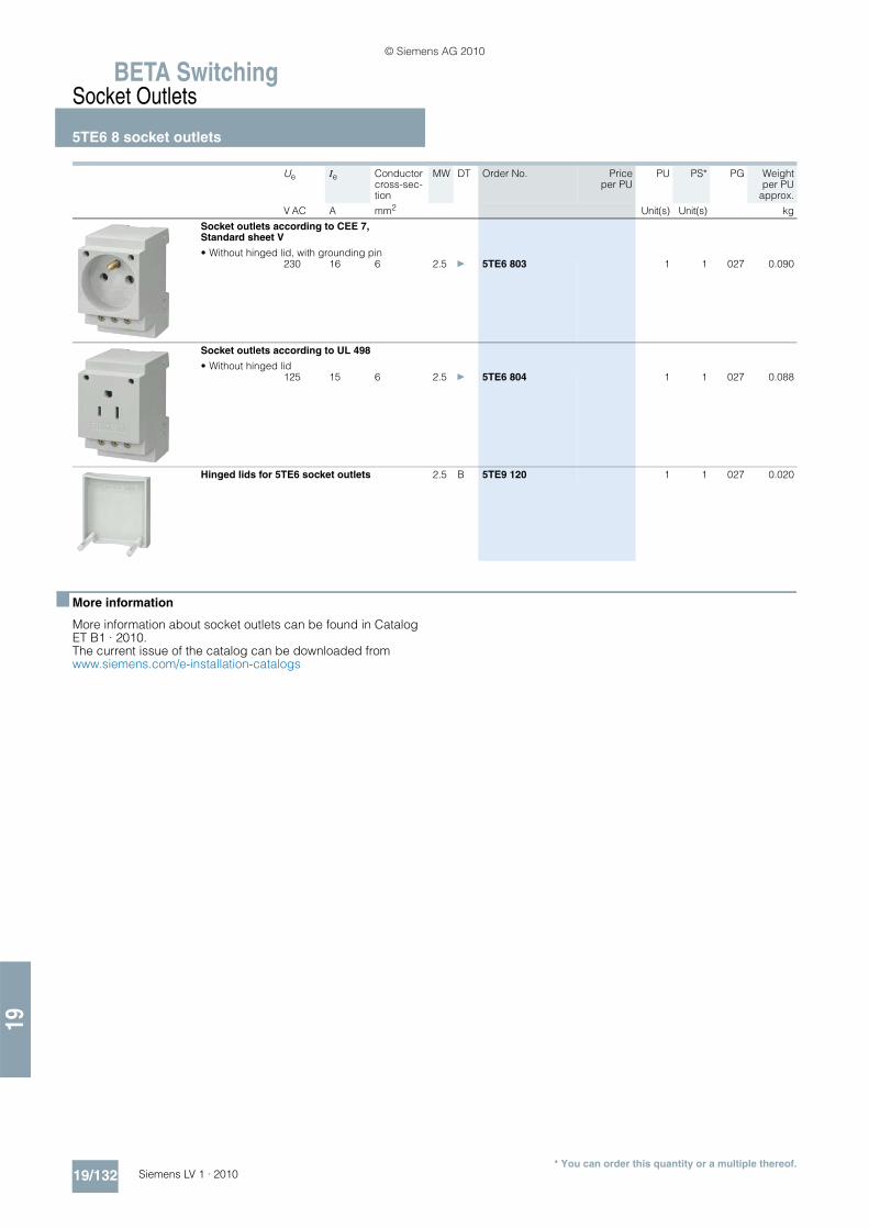
BETA SwitchingSocket Outlets
5TE6 8 socket outlets
19/132 Siemens LV 1 · 2010
19
* You can order this quantity or a multiple thereof.
■ More information
More information about socket outlets can be found in Catalog ET B1 · 2010. The current issue of the catalog can be downloaded from www.siemens.com/e-installation-catalogs
Ue Ie Conductor cross-sec-tion
MW DT Order No. Priceper PU
PU PS* PG Weightper PU
approx.
V AC A mm2 Unit(s) Unit(s) kg
Socket outlets according to CEE 7, Standard sheet V
• Without hinged lid, with grounding pin230 16 6 2.5 } 5TE6 803 1 1 027 0.090
Socket outlets according to UL 498
• Without hinged lid125 15 6 2.5 } 5TE6 804 1 1 027 0.088
Hinged lids for 5TE6 socket outlets 2.5 B 5TE9 120 1 1 027 0.020
© Siemens AG 2010

19
BETA MeasuringThree-Phase Measuring Devices
7KT1 30 multimeters
19/133Siemens LV 1 · 2010* You can order this quantity or a multiple thereof.
■ Overview
Multimeters are mainly used in power distribution boards for in-feeds into buildings and plants. They replace the more common analog voltmeters and ammeters with measuring point changeover, as well as measuring devices for power outputs and power factor p.f.
The standard measured quantity to be indicated in the 5 display fields of the multimeter can be tailored to customer require-ments. Versions for direct connection 63 A or for transformers /5 A with adjustable transformer primary current from 5 to 5000 A support a wide range of applications.
The green 7-segment displays for the measured values and the orange indicators of the units of measurement directly alongside the measured values make for easy reading.
■ Benefits
• Clear display of all necessary measured values• All measured values can be read from a distance• Customized setting of the measured quantities for the stan-
dard display• Wide range of application thanks to flexible adaptation to
measuring current transformers• Detection of connection errors during start-up saves consider-
able time when trying to locate faults • Large, 11 mm high, green 7-segment displays for measured
values makes for easy reading• Indication of units of measurement directly alongside the re-
lated measured values provide a clear overview.
■ Selection and ordering data
Ue Ie Uc MW DT Order No. Priceper PU
PU PS* PG Weightper PU
approx.
V AC A AC V AC Unit(s) Unit(s) kg
Multimeters
For the display of 23 electrical values, of which 5 values can be continuously displayed.
7KT1 300
Standard rail mounting
For direct connection
3 × 230/400 63 230 6 B 7KT1 300 1 1 027 0.400
For transformer connection 5 ... 5000 A, adjustable in 5 A increments, secondary current 5 A
3 × 230/400 Trans-former /5
230 6 B 7KT1 301 1 1 027 0.380
7KT1 302
Front mounting
For transformer connection 5 ... 5000 A, adjustable in 5 A increments, secondary current 5 A, mounting dimensions 96 mm × 96 mm
3 × 230/400 Trans-former /5
230 -- B 7KT1 302 1 1 027 0.378
© Siemens AG 2010

BETA MeasuringThree-Phase Measuring Devices
7KT1 30 multimeters
19/134 Siemens LV 1 · 2010
19
■ More information
Voltage measurement
The multimeter measures the delta voltages L1 against L2; L2 against L3 and L3 against L1 or the star voltages L1, L2, L3 against N.
�L symbol for the three-phase system
This indicates that all physical units shown under this symbol are always 3 phase.
Readout data
You can continuously display 5 measured quantities from the fol-lowing 23 options.
Matrix selection
Conventional measuring instruments display voltages, currents, powers, etc. in a rigid sequence on several "screens". These multimeters allow users to define their own standard for mea-sured quantities per display field, so that they can be imple-mented far more universally and flexibly.
A special feature is the analysis of the different loads on the phases. Phase displacement and unsymmetrical or unbalanced loads can cause partial overloads. These multimeters offer a range of different options for combining and assessing mea-sured values.
The display fields are selected using rotary switches and the de-sired indications confirmed with OK. By making the horizontal selection e. g. W, V, A or p.f., and the vertical selection, e. g. L1, L1 – L2 or �L, users can then define the desired measured quantities for this display field.
The vertical data on the display can be assigned to any mea-sured value in the horizontal data. The letters M(ega) and k(ilo) are automatically assigned according to measuring range, i. e. measured value, e. g. kW or MW. Capacitive loads are automat-ically indicated by a capacitor, inductive loads by a coil.
The following diagram shows an example of what your matrix se-lection might look like.
More information about multimeters can be found in Catalog ET B1 · 2010. The current issue of the catalog can be downloaded from www.siemens.com/e-installation-catalogs.
No. Measured value Display Unit Assign-ment
1 Active power D1 W L1
2 Voltage D1 V L1
3 Current D1 A L1
4 Apparent power D1 VA L1
5 P.f. D1 P.f. L1
6 Voltage D1 V L1 – L2
7 Active power D2 W L2
8 Voltage D2 V L2
9 Current D2 A L2
10 Apparent power D2 VA L2
11 P.f. D2 P.f. L2
12 Voltage D2 V L2 – L3
13 Active power D3 W L3
14 Voltage D3 V L3
15 Current D3 A L3
16 Apparent power D3 VA L3
17 P.f. D3 P.f. L3
18 Voltage D3 V L3 – L1
19 Active power D1, D2, D3, D5 W �L
20 Apparent power D1, D2, D3, D5 VA �L
21 reactive power D5 var �L
22 Frequency D4 Hz �L
23 P.f. D1, D2, D3, D4 P.f. �L
2 set values are also indicated:
24 Transformer setting D5 CT/A /5
25 Transformer setting CT/A 5 ... 5000
l1
L1-N
L1-L2
L1
L2L3
L3-L1
l2
l3
L3-N L2-N
N
L2-L3I2_08410b
1
2
3
I2_10803a
L1k W
A
L2 L3OKk W k W
L
COS
© Siemens AG 2010

19
BETA MeasuringThree-Phase Measuring Devices
7KT1 31, 7KT1 34, 7KT1 35 multicounters
19/135Siemens LV 1 · 2010* You can order this quantity or a multiple thereof.
■ Overview
Multicounters are mainly used in power distribution boards for in-feeds into buildings and plants. They replace the more common analog voltmeters and ammeters with measuring point changeover, as well as measuring devices for power outputs and power factor p.f.
The standard measured quantity to be indicated in the 6 display fields of the multicounter can be tailored to customer require-ments. The measured values of all measured quantities can also be displayed quickly and easily over the operator buttons. Ver-sions for direct connection 63 A or for transformers /5 A with ad-justable transformer primary current from 5 to 5000 A support a wide range of applications.
The green 7-segment displays for the measured values and the orange indicators of the units of measurement directly alongside the measured values make for easy reading.
■ Benefits
• Clear display of all necessary measured values • All measured values can be read from a distance • Customized setting of the measured quantities for the stan-
dard display Fast display of all measured quantities over op-erator buttons
• Wide range of application thanks to flexible adaptation to measuring current transformers
• Detection of incorrect connections during installation• Communication with LAN, Modbus or PROFIBUS DP enables
integration in an energy management system• Software package for data transmission over LAN and visual-
ization of measured data with Microsoft EXCEL enables imple-mentation of customized solutions.
■ Selection and ordering data
Ue Ie Uc MW DT Order No. Priceper PU
PU PS* PG Weightper PU
approx.
V AC A AC V AC Unit(s) Unit(s) kg
Multicounters
For the display of 35 electrical values, of which 5 or 6 values can be continuously displayed. For three-phase, 3/4 conductor connection, with S0 interface
Without communication interface
7KT1 310
Standard rail mounting
For direct connection
3 × 230/400 63 230 6 B 7KT1 310 1 1 027 0.420
For transformer connection 5 ... 5000 A, adjustable in 5 A increments, secondary current 5 A
3 × 230/400 Trans-former /5
230 6 B 7KT1 311 1 1 027 0.410
7KT1 312
Front mounting
For transformer connection 5 ... 5000 A, adjustable in 5 A increments, secondary current 5 A, mounting dimensions 96 mm × 96 mm
3 × 230/400 Trans-former /5
230 -- B 7KT1 312 1 1 027 0.410
With RS485 interface and RTU Modbus proto-col or for connection to LAN networks over 7KT1 390 LAN coupler
Standard rail mounting
For direct connection
3 × 230/400 63 230 6 B 7KT1 340 1 1 027 0.470
For transformer connection 5 ... 5000 A, adjustable in 5 A increments, secondary current 5 A
3 × 230/400 Trans-former /5
230 6 B 7KT1 341 1 1 027 0.423
Front mounting
For transformer connection 5 ... 5000 A, adjustable in 5 A increments, secondary current 5 A, mounting dimensions 96 mm × 96 mm
3 × 230/400 Trans-former /5
230 -- B 7KT1 342 1 1 027 0.397
© Siemens AG 2010
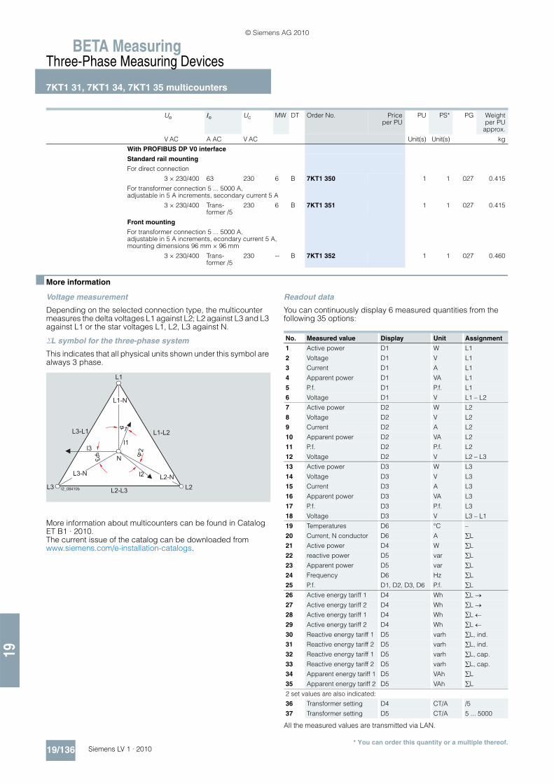
BETA MeasuringThree-Phase Measuring Devices
7KT1 31, 7KT1 34, 7KT1 35 multicounters
19/136 Siemens LV 1 · 2010
19
* You can order this quantity or a multiple thereof.
■ More information
Voltage measurement
Depending on the selected connection type, the multicounter measures the delta voltages L1 against L2; L2 against L3 and L3 against L1 or the star voltages L1, L2, L3 against N.
�L symbol for the three-phase system
This indicates that all physical units shown under this symbol are always 3 phase.
More information about multicounters can be found in Catalog ET B1 · 2010. The current issue of the catalog can be downloaded from www.siemens.com/e-installation-catalogs.
Readout data
You can continuously display 6 measured quantities from the following 35 options:
All the measured values are transmitted via LAN.
Ue Ie Uc MW DT Order No. Priceper PU
PU PS* PG Weightper PU
approx.
V AC A AC V AC Unit(s) Unit(s) kg
With PROFIBUS DP V0 interface
Standard rail mounting
For direct connection
3 × 230/400 63 230 6 B 7KT1 350 1 1 027 0.415
For transformer connection 5 ... 5000 A, adjustable in 5 A increments, secondary current 5 A
3 × 230/400 Trans-former /5
230 6 B 7KT1 351 1 1 027 0.415
Front mounting
For transformer connection 5 ... 5000 A, adjustable in 5 A increments, econdary current 5 A, mounting dimensions 96 mm × 96 mm
3 × 230/400 Trans-former /5
230 -- B 7KT1 352 1 1 027 0.460
l1
L1-N
L1-L2
L1
L2L3
L3-L1
l2
l3
L3-N L2-N
N
L2-L3I2_08410b
1
2
3
No. Measured value Display Unit Assignment
1 Active power D1 W L1
2 Voltage D1 V L1
3 Current D1 A L1
4 Apparent power D1 VA L1
5 P.f. D1 P.f. L1
6 Voltage D1 V L1 – L2
7 Active power D2 W L2
8 Voltage D2 V L2
9 Current D2 A L2
10 Apparent power D2 VA L2
11 P.f. D2 P.f. L2
12 Voltage D2 V L2 – L3
13 Active power D3 W L3
14 Voltage D3 V L3
15 Current D3 A L3
16 Apparent power D3 VA L3
17 P.f. D3 P.f. L3
18 Voltage D3 V L3 – L1
19 Temperatures D6 °C –
20 Current, N conductor D6 A �L
21 Active power D4 W �L
22 reactive power D5 var �L
23 Apparent power D5 var �L
24 Frequency D6 Hz �L
25 P.f. D1, D2, D3, D6 P.f. �L
26 Active energy tariff 1 D4 Wh �L �27 Active energy tariff 2 D4 Wh �L �28 Active energy tariff 1 D4 Wh �L �29 Active energy tariff 2 D4 Wh �L �30 Reactive energy tariff 1 D5 varh �L, ind.
31 Reactive energy tariff 2 D5 varh �L, ind.
32 Reactive energy tariff 1 D5 varh �L, cap.
33 Reactive energy tariff 2 D5 varh �L, cap.
34 Apparent energy tariff 1 D5 VAh �L
35 Apparent energy tariff 2 D5 VAh �L
2 set values are also indicated:
36 Transformer setting D4 CT/A /5
37 Transformer setting D5 CT/A 5 ... 5000
© Siemens AG 2010

19
BETA MeasuringThree-Phase Measuring Devices
7KT1 39 LAN couplers
19/137Siemens LV 1 · 2010* You can order this quantity or a multiple thereof.
■ Overview
A LAN coupler supports the worldwide data recall of up to 10 multicounters and E-counters over a LAN link to the Internet.
The LAN coupler is used in conjunction with multicounters and E-counters. Up to 10 devices can be linked with a LAN coupler. In turn, the LAN coupler is connected to a LAN.
Data communication between the LAN coupler and the PC takes place using the TCP/IP protocol.
The supplied software can be used to call up the measured data over LAN coupler and transfer it to a PC. The measured data are continuously stored as a text file with time and date stamp. This gives users great flexibility in designing their own solutions (e. g. the data can be prepared using MS Excel).
■ Benefits
• Integration of measuring devices in industrial or office commu-nication
• Display of measured data using the standard software MS Ex-cel
• Use of existing local networks (LAN) for transmitting the mea-sured data
• TCP/IP data protocol enables a wide range of applications• Limit value signals with time information for all measured val-
ues increases your plant's safety• Open software structure enables the implementation of cus-
tomized solutions for measured data indication and analysis• Worldwide communication of the measured values via LAN• One LAN coupler for 10 devices
■ Selection and ordering data
■ More information
Connection of the LAN coupler to a LAN
Each station in a LAN must be assigned its own IP address. On delivery, or after a reset, the LAN coupler has a standard IP ad-dress. The new IP address must be set in the LAN coupler dur-ing start-up. To do this, the LAN coupler must be directly con-nected to a PC using a so-called "cross-over" cable. This is a network cable in which the transmit and receive wires are cross-connected. This creates a small LAN with 2 stations, PC and LAN coupler can communicate with each other directly. The supplied LAN coupler configuration tool must be installed on the PC. This direct connection can then be used to set a new IP ad-dress in the LAN coupler, as well as other network parameters, such as subnet mask and default gateway. The LAN coupler must then be connected to the target system as communication is subsequently only possible with the new settings.
Connection of measuring devices to the LAN coupler
E-counters and multicounters are connected to the LAN couplers over their communication interface. The network is an RS 485 network in which devices are connected over a shielded 2-wire cable. When using Modbus, the device address and transmission rate must be set in the multicounters. This is not necessary if using the multicounters and E-counters over the LAN coupler, as the LAN coupler automatically detects and identifies any connected E-counters and multicounters. You can now use the LAN coupler configuration tool (over the LAN net-work) to tell the LAN coupler from which device you want to re-trieve the measured data.
The LAN coupler carries out a so-called "polling" during runtime. This cyclically retrieves the most recently gathered measured data from the measuring devices and buffers them in the LAN coupler. This can then be called up at any time over the LAN.
Uc MW DT Order No. Priceper PU
PU PS* PG Weightper PU
approx.
V AC Unit(s) Unit(s) kg
LAN couplers
For connection of up to 10 devices over RS485Software tools included for:
• Installation and commissioning
• Data transmission and storage
• MS Excel macro for visualization of measured data
230 4 B 7KT1 390 1 1 027 0.232
© Siemens AG 2010

BETA MeasuringThree-Phase Measuring Devices
7KT1 39 LAN couplers
19/138 Siemens LV 1 · 2010
19
Data transmission from LAN coupler to PC
This data transmission is PC-controlled. A software tool runs in the background on the PC and uses the network to cyclically re-trieve any measured data from all available LAN couplers and save it to the hard disk.
Software tool
The supplied software tool has the following functions:• Background transmission of measurement data from multi-
counters and E-counters and a number of LAN couplers• Full display of device measured data through a macro based
on MS Excel• Adjustable limit value signals for measured quantities• Violations of limit values are signaled with time stamp.
You will find further information on Modbus operation on the In-ternet at: www.siemens.com/beta
Display of measured data on the PC
A Visual Basic macro for MS Excel is supplied with the LAN cou-pler for the display of measured data on a PC. Among other things, this software tool lets you display all 35 measured data of a 7KT1 34 multicounter on a single panel. You can then select the various measuring devices you want to display from a small list box. The software also lets you set alarm limits for up to 10 measured quantities of a multicounter.
If a measured value exceeds or falls below the specified limits, the relevant indication is output, complete with time stamp from the PC clock.
Display of measured data of a multicounter
Simultaneous display of measured data on more than one PC
The software supplied with the LAN coupler supports display of measured data on any number of PCs connected to the network over a client-server architecture.
A PC acts as the server, similar to an Intranet or Internet server. This PC runs the software components that retrieve the measure-ment data from the LAN coupler and save it to hard disk. The MS Excel macro can be used to visualize the measured data on both the server PC and the clients.
Other client PCs can access the data pool of the server PC to vi-sualize the measured data.
Open software architecture
The architecture of the software tool is open and can be custom-ized to suit user requirements. The MS Excel macros are freely accessible and can also be customized by the user.
Block diagram of a system
TCP/IPnetwork
PC Clients- Communication software- MS EXCEL visualization- Configuration tool (only required for configuration of the LAN coupler)
LAN coupler
Measuring device 10 I201_13445
RS485
Measuring device 2
LAN couplerLAN coupler
Measuring device 1
© Siemens AG 2010

19
BETA MeasuringThree-Phase Measuring Devices
7KT1 5 E-counters
19/139Siemens LV 1 · 2010* You can order this quantity or a multiple thereof.
■ Overview
The E-counters (power meters) are used to record the amount of electrical energy exported or imported. Siemens compact E-counters are designed as modular devices for alternating cur-rent and can be mounted on standard mounting rails. They com-ply with the counter standard EN 50470-1 and -3 and come with an LCD.
The three-phase counters are available for direct connection up to 80 A and also in versions with transformer connection (…/5 A to 10000/5 A).
The E-counters store both active energy and reactive energy and they all comply with accuracy class 1 (for active energy).
All E-counters have a pulse output (S0) and are designed for 2 tariff measurements. The calibrated versions are in accor-dance with the new Measuring Instruments Directive 2004/22/EC (MID).
At the same time the E-counters have an integrated optical inter-face (IrDA) for connecting communication modules. Integration of the E-counters, e. g. in energy management systems, is thus possible.
For single-phase E-counters see page 19/141.
■ Benefits
• Compliant with the new counter standard EN 50470-1 and -3• Easy-to-read LCD• Versions calibrated in accordance with the new Measuring In-
struments Directive 2004/22/EC (MID) can be used for invoic-ing purposes
• Exact recording thanks to accuracy class 1 (for active energy)
• Direct connection up to 80 A, transformer current connection .../5 A
• Sealable terminal covers
■ Selection and ordering data
■ More information
More information about E-counters can be found in Catalog ET B1 · 2010. The current issue of the catalog can be downloaded from www.siemens.com/e-installation-catalogs.
Ue Ie Uc MW DT Order No. Priceper PU
PU PS* PG Weightper PU
approx.
V AC A AC V AC Unit(s) Unit(s) kg
Digital three-phase E-counters
For direct connection, double rate230 80 230 4 B 7KT1 543 1 1 027 0.386
For direct connection, double rate, calibrated version
230 80 230 4 B 7KT1 545 1 1 027 0.386
For transformer connection, double rate230 Trans-
former /5230 4 B 7KT1 540 1 1 027 0.281
© Siemens AG 2010

BETA MeasuringThree-Phase Measuring Devices7KT1 2 current transformers7KT9 0 measuring selector switches
19/140 Siemens LV 1 · 2010
19
■ Overview
7KT1 2 current transformers
This three-phase current transformer can be used in distribution boards according to DIN 43880. The measuring leads are routed vertically through the standard mounting rail.This type of current transformer is suitable for incoming or out-going feeders in connection with the installation of a 5TE8 switch or a 5TE1 disconnector, as the primary connecting leads do not have to be interrupted.
The current transformer is designed for cables of up to 13 mm in diameter, e. g. H07V-R with 50 mm2 conductor cross-section.
■ Benefits
• The current transformer has accuracy class 1 in accordance with EN 60044-1. This value is better than most measuring de-vices in this area of application.
• The versions designed for a transformer ratio of 60/5 A, 100/5 A and 150/5 A enable an even broader range of appli-cations.
■ Selection and ordering data
■ Overview
7KT9 0 measuring selector switches
Measuring selector switches are used as CO contacts of the phases for voltages and currents in three-phase systems for volt-meters and ammeters.
The design of these switches is adapted to match the modular installation devices. They support use in compliance with EN 60947-3.
■ Benefits
• The devices have a rated insulation voltage of 660 V. This per-mits use in many systems.
■ Selection and ordering data
Ue Ie Isec MW DT Order No. Priceper PU
PU PS* PG Weightper PU
approx.
V AC A AC A AC Unit(s) Unit(s) kg
Current transformers
720 3 × 60 5 6 B 7KT1 200 1 1 027 0.4603 × 100 B 7KT1 201 1 1 027 0.4603 × 150 B 7KT1 202 1 1 027 0.465
Ue Ie Uc MW DT Order No. Priceper PU
PU PS* PG Weightper PU
approx.
V AC A AC V AC Unit(s) Unit(s) kg
Voltmeter selector switches
400 12 6 3 A 7KT9 010 1 1/48 027 0.110
Ammeter selector switches for operation with current transformer
400 12 6 3 A 7KT9 011 1 1 027 0.110
© Siemens AG 2010

19
BETA MeasuringSingle-Phase Measuring Devices
7KT1 53, 7KT1 14 E-counters
19/141Siemens LV 1 · 2010* You can order this quantity or a multiple thereof.
■ Overview
The E-counters (power meters) are used to record the amount of electrical energy exported or imported. Siemens compact E-counters are designed as modular devices for alternating cur-rent and can be mounted on standard mounting rails. They com-ply with the counter standard EN 50470-1 and -3 and come with an LCD.
The single-phase counters are available for direct connection up to 80 A. They store both active energy and reactive energy and they all comply with accuracy class 1 (for active energy).
All E-counters have a pulse output (S0) and are designed for 1-tariff or 2-tariff measurements depending on the version. The cal-ibrated versions are in accordance with the new Measuring In-struments Directive 2004/22/EC (MID).
At the same time the E-counters have an integrated optical inter-face (IrDA) for connecting communication modules. Integration of the E-counters, e. g.in energy management systems, is thus possible.
For three-phase E-counters see page 19/139.
■ Benefits
Digital 7KT1 53. E-counters• Compliant with the new counter standard EN 50470-1 and -3• Easy-to-read LCD• Versions calibrated in accordance with the new Measuring In-
struments Directive 2004/22/EC (MID) can be used for invoic-ing purposes
• Exact recording thanks to accuracy class 1 (for active energy)• Sealable terminal covers
• Direct connection up to 80 A
7KT1 140 E-counters for active energy• The drum-type register with digit size 4 mm × 1.2 mm enables
easy reading• The short-circuit proof pulse output protects the device if it is
assembled incorrectly.
■ Selection and ordering data
■ More information
More information about E-counters can be found in Catalog ET B1 · 2010. The current issue of the catalog can be downloaded from www.siemens.com/e-installation-catalogs
Ue Ie Uc MW DT Order No. Priceper PU
PE PS*/P. unit
PG Weightper PU
approx.
V AC AC A V AC Unit(s) Unit(s) kg
Digital single-phase E-counters
• For direct connection, single rate80 4 B 7KT1 530 1 1 027 0.164
• For direct connection, double rate80 4 B 7KT1 531 1 1 027 0.164
• For direct connection, double rate, calibrated version
80 4 B 7KT1 533 1 1 027 0.164
E-counters for active energy
With 7-digit drum-type register 4 mm × 1.2 mmwith S0 interface, for single-phase operation
Direct connection, single rate
230 80 230 2 B 7KT1 140 1 1 027 0.400
© Siemens AG 2010

BETA MeasuringSingle-Phase Measuring Devices7KT1 11, 7KT1 12 digital measuring devices7KT1 0 analog measuring devices
19/142 Siemens LV 1 · 2010
19
* You can order this quantity or a multiple thereof.
■ Overview
7KT1 11, 7KT1 12 digital measuring devices
These devices for measuring voltages and currents can be used for monitoring incoming and outgoing currents or device cur-rents in electric plants. They are suitable for direct connection in a single-phase system or with measuring transducers in three-phase systems.
The measuring ranges of the ammeter are set at the device with a coding switch.
■ Benefits
• The ammeters have 14 measuring ranges from 0 ... 20 A to 0 ... 999 A, which can be set using a coding switch. This en-sures universal application.
■ Selection and ordering data
■ More information
More information about digital measuring devices can be found in Catalog ET B1 · 2010.
The current issue of the catalog can be downloaded from www.siemens.com/e-installation-catalogs
■ Overview
7KT1 0 analog measuring devices
These devices for measuring voltages and currents can be used for monitoring incoming and outgoing currents or device cur-rents in electric plants. They are suitable for direct connection in a single-phase system or with measuring transducers in three-phase systems.
■ Benefits
• The 7KT1 020 ammeter can be equipped with changeable scales for primary currents of 60, 150 or 400 A AC, depending on the transformer ratio of the installed current transformer. The changeable scales are included in the scope of delivery. This ensures universal application.
• Permanent overload up to 20 % does not damage the device. This means safety for your plant.
■ Selection and ordering data
Ue Ie Uc MW DT Order No. Priceper PU
PE PS*/P. unit
PG Weightper PU
approx.
V AC AC A V AC Unit(s) Unit(s) kg
Digital voltmeters
230 600 2 B 7KT1 110 1 1 027 0.190
Digital ammeters for direct and current transformer connection
230 0 ... 20 trans-formers/5
2 B 7KT1 120 1 1 027 0.200
Umeas Imeas MW DT Order No. Priceper PU
PE PS*/P. unit
PG Weightper PU
approx.
V AC AC A Unit(s) Unit(s) kg
Analog voltmeters
500 4 B 7KT1 000 1 1 027 0.105
Analog ammeters for direct connection
25 4 B 7KT1 010 1 1 027 0.11040 B 7KT1 011 1 1 027 0.12560 B 7KT1 012 1 1 027 0.135
Analog ammeters for current transformer connection with 3 different interchangeable scales
0 ... 60 A, 0 ... 150 A and 0 ... 400 A
0 ... 60/5 0 ... 150/5 0 ... 400/5
4 B 7KT1 020 1 1 027 0.105
© Siemens AG 2010

19
BETA MeasuringSingle-Phase Measuring Devices
7KT5 8 time and pulse counters
19/143Siemens LV 1 · 2010* You can order this quantity or a multiple thereof.
■ Overview
Time and pulse counters are used for the reliable monitoring of production and service times, which enables the exact planning and monitoring of production sequences, maintenance cycles and warranty times.
As well as the proven electromechanical time and pulse counters for mounting in distribution boards, we also supply dig-ital time and pulse counters.
The fields of application for both counter types are very diverse, such as the recording of operating hours of machines, systems or building management systems, as well as pulse counting for general volume flow counting, registration of starting frequen-cies, starting cycles or production quantities in systems and ma-chines.
■ Benefits
• Time and pulse counters help to plan maintenance intervals and ensure high plant availability.
• Versions without zero position and with electric or manual zero position for all applications.
• Flexible application of the digital counters for control supply voltages of 12 to 150 V DC and 24 to 240 V AC in a single de-vice.
■ Selection and ordering data
■ More information
More information about time and pulse counters can be found in Catalog ET B1 · 2010. The current issue of the catalog can be downloaded from www.siemens.com/e-installation-catalogs
Uc Fre-quency
MW DT Order No. Priceper PU
PE PS*/P. unit
PG Weightper PU
approx.
V Hz Unit(s) Unit(s) kg
Time counters
Mechanical counting mechanism, display 00000.00 h without resetting
12 ... 24 -- 2 A 7KT5 801 1 1 027 0.095
24 AC 50 A 7KT5 802 1 1 027 0.095115 AC B 7KT5 803 1 1 027 0.095230 AC A 7KT5 804 1 1 027 0.095
115 AC 60 B 7KT5 806 1 1 027 0.095230 AC B 7KT5 807 1 1 027 0.095
Pulse counters
Mechanical counting mechanism, display 0000000 without zero position
12 ... 24 -- 2 B 7KT5 811 1 1 027 0.095
24 AC 50/60 B 7KT5 812 1 1 027 0.095230 AC B 7KT5 814 1 1 027 0.095
Electronic time counters
LCD 000000.0 h without zero position
12 ... 150 DC, 24 ... 240
--50/60
2 B 7KT5 821 1 1 027 0.080
with electrical resetting
12 ... 150 DC, 24 ... 240
--50/60
B 7KT5 822 1 1 027 0.080
with electrical and mechanical resetting
12 ... 150 DC, 24 ... 240
--50/60
B 7KT5 823 1 1 027 0.080
Electronic pulse counters
LCD display 0000000
with electrical and mechanical resetting
12 ... 150 DC, 24 ... 240
--50/60
2 B 7KT5 833 1 1 027 0.080
© Siemens AG 2010

BETA MeasuringSingle-Phase Measuring Devices
7KT5 5, 7KT5 6 time counters for front mounting
19/144 Siemens LV 1 · 2010
19
* You can order this quantity or a multiple thereof.
■ Overview
Time and pulse counters for control cabinets, control and me-chanical engineering are used, e. g. in boilers, machine tools or compressors. The pulse counters count the starting frequencies. This supports planning for preventative maintenance.
In-time and regular maintenance is the best protection against unexpected shutdowns.
■ Benefits
• Time and pulse counters help to plan maintenance intervals and ensure high plant availability.
■ Selection and ordering data
Uc Fre-quency
MW DT Order No. Priceper PU
PE PS*/P. unit
PG Weightper PU
approx.
V Hz Unit(s) Unit(s) kg
Time counters
Mechanical counting mechanism, display 00000.00 h, for front-panel mounting, front frame 48 mm x 48 mm
10 ... 80 – A 7KT5 500 1 1 027 0.045
24 AC 50 A 7KT5 505 1 1 027 0.045115 AC A 7KT5 501 1 1 027 0.045230 AC A 7KT5 502 1 1 027 0.045
115 AC 60 A 7KT5 503 1 1 027 0.045230 AC A 7KT5 504 1 1 027 0.045
For front-panel mounting, front frame 72 mm x 72 mmwith narrow frame according to DIN 43700
10 ... 50 – 2 B 7KT5 600 1 1 027 0.120
115 AC 50 B 7KT5 601 1 1 027 0.120230 AC A 7KT5 602 1 1 027 0.120
115 AC 60 B 7KT5 603 1 1 027 0.120230 AC B 7KT5 604 1 1 027 0.120
Covers for 7KT5 5 time counters
55 mm × 55 mm B 7KT9 020 1 1 027 0.015
Sealing rings for 7KT9 020 covers
IP43 installation in switchboards with smooth surfaces C 7KT9 000 1 set 1 set 027 0.020(1 set = 5 units)
Terminal covers for 7KT5 6 time counters
Degree of protection IP20 with connected conductors B 7KT9 021 1 1 027 0.010
© Siemens AG 2010