Embed Size (px)
Citation preview

PARTS LISTING WITHMOUNTING AND OPERATINGINSTRUCTIONS
SIDE / REARFLAIL
ASSEMBLIESFord 81-8560, CAB
32836
Tiger Corporation3301 N. Louise Ave.
Sioux Falls, SD 571071-800-843-68491-605-336-7900
www.tiger-mowers.com
Current as of 04/22/05

TO THE OWNER / OPERATOR / DEALERAll implements with moving parts are potentially hazardous. There is no substitute for a cautious,
safe-minded operator who recognizes the potential hazards and follows reasonable safety practices.The manufacturer has designed this implement to be used with all its safety equipment properlyattached to minimize the chance of accidents.
BEFORE YOU START!! Read the safety messages on the implement and shown in this manual.Observe the rules of safety and use common sense!
READ AND UNDERSTAND THIS MANUAL! Non–English speaking operators will need to GETTHE MANUAL TRANSLATED as needed!
Warranty Information: Read and understand the complete Warranty Statement found in this manual. Fill out theWarranty Registration form in full and return it within 90 days. Make certain the Serial Number of the machine isrecorded on the Warranty Card, and form that you retain.

FORWARD
This manual contains information about many features of the Tiger mowingand roadside maintenance equipment. Some of these include: Safety precautions,Assembly instructions, Operations, Maintenance and Parts. This manual will alsoassist you in the proper break-in, daily care, and troubleshooting of your newmower.
We recommend that you read carefully the entire manual before operating theunit. Also, time spent in becoming fully acquainted with its performance features,adjustments, and maintenance schedules will be repaid in a long and satisfactorylife of the equipment.
Troubleshooting - Please, before you call, help us to help you!Please look at the equipment to observe what is happening, then:• Classify the problem
• Hydraulic, electrical or mechanical - Read the trouble shooting section• Tractor or Truck chassis - Contact vehicle dealer
• If unable to correct the problem yourself, contact your local Tiger Dealer after gathering:
• Machine model _______________________• Serial number ________________________• Dealer name _________________________• Detailed information about the problem including results of troubleshooting
Attention Owner / Operator / Dealer: It is your obligation to read, and understand,the warranty information section located at the back of this manual denoting that thepurchaser understands the safety issues relating to this machine and has receivedand will read a copy of this manual.
If at any time, you have a service problem with your Tiger mower, Contactyour local dealer for service and parts needed.
MANUFACTURED BY: DISTRIBUTED BY:Tiger Corporation _____________________3301 N. Louise Ave. _____________________Sioux Falls, SD 57107 1-_____-_____-________1-800-843-6849 1-_____-_____-________1-605-336-7900www.tiger-mowers.com

TABLE OF CONTENTS
SAFETY_____________________________________________ 1-1Safety Information__________________________________ 1-2
ASSEMBLY / MOUNTING SECTION_______________________2-1
OPERATION SECTION_________________________________ 3-1
MAINTENANCE SECTION______________________________ 4-1
PARTS SECTION_____________________________________ 5-1Parts Ordering Guide_______________________________ 5-2Parts Table of Contents______________________________ 5-3
Common Parts Section____________________________ 6-1
WARRANTY INFORMATION_____________________________ 7-1
This symbol means:
CAUTION – YOUR SAFETY IS AT RISK!When you see this symbol, read and
follow the associated instructions carefullyor personal injury or damage may result.
Tiger is a registered trademark.

SAFETYSECTION
Safety Section 1-1

Safety Section 1-2
SAFETY
Indicates an imminently hazardous situation that, if not avoided, WILL result in DEATHOR VERY SERIOUS INJURY.
Indicates an imminently hazardous situation that, if not avoided, COULD result inDEATH OR SERIOUS INJURY.
Indicates an imminently hazardous situation that, if not avoided, MAY result in MINORINJURY.
Identifies special instructions or procedures that, if not strictly observed, could resultin damage to, or destruction of the machine, attachments or the enviroment.
NOTE: Identifies points of particular interest for more efficient or convienient operation orrepair. (SG-1)
General Safety Instructions and PracticesA safe and careful operator is the best operator. Safety is of primary importance to themanufacturer and should be to the owner / operator. Most accidents can be avoided by beingaware of your equipment, your surroundings, and observing certain precautions. The firstsection of this manual includes a list of Safety Messages that, if followed, will help protect theoperator and bystanders from injury or death. Read and understand these Safety Messagesbefore assembling, operating or servicing this mower. This equipment should only beoperated by those persons who have read the Manual, who are responsible and trained, andwho know how to do so safely and responsibly.
The Safety Alert Symbol combined with a Signal Word, as seen below, is usedthroughout this manual and on decals which are attached to the equipment. TheSafety Alert Symbol means: “ATTENTION! BECOME ALERT! YOUR SAFETY ISINVOLVED!” The symbol and signal word are intended to warn the owner /operator of impending hazards and the degree of possible injury when operatingthis equipment.
Practice all usual and customary safe working precautions andabove all -- remember safety is up to YOU! Only YOU can
prevent serious injury or death from unsafe practices.
READ, UNDERSTAND, and FOLLOW the following Safety Messages.Serious injury or death may occur unless care is taken to follow thewarnings and instructions stated in the Safety Messages. Always usegood common sense to avoid hazards. (SG-2)
IMPORTANT!
Safety Section 1-3
SAFETY
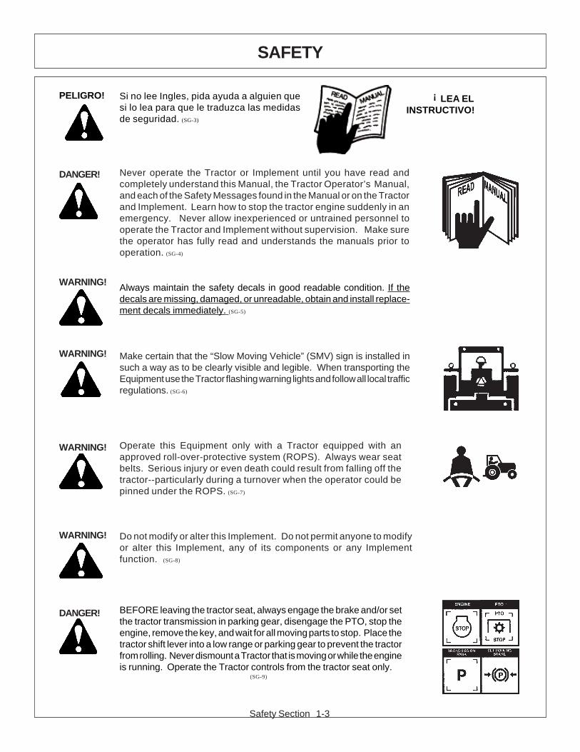
DANGER! Never operate the Tractor or Implement until you have read andcompletely understand this Manual, the Tractor Operator’s Manual,and each of the Safety Messages found in the Manual or on the Tractorand Implement. Learn how to stop the tractor engine suddenly in anemergency. Never allow inexperienced or untrained personnel tooperate the Tractor and Implement without supervision. Make surethe operator has fully read and understands the manuals prior tooperation. (SG-4)
WARNING! Always maintain the safety decals in good readable condition. If thedecals are missing, damaged, or unreadable, obtain and install replace-ment decals immediately. (SG-5)
WARNING! Make certain that the “Slow Moving Vehicle” (SMV) sign is installed insuch a way as to be clearly visible and legible. When transporting theEquipment use the Tractor flashing warning lights and follow all local trafficregulations. (SG-6)
WARNING! Operate this Equipment only with a Tractor equipped with anapproved roll-over-protective system (ROPS). Always wear seatbelts. Serious injury or even death could result from falling off thetractor--particularly during a turnover when the operator could bepinned under the ROPS. (SG-7)
WARNING! Do not modify or alter this Implement. Do not permit anyone to modifyor alter this Implement, any of its components or any Implementfunction. (SG-8)
DANGER! BEFORE leaving the tractor seat, always engage the brake and/or setthe tractor transmission in parking gear, disengage the PTO, stop theengine, remove the key, and wait for all moving parts to stop. Place thetractor shift lever into a low range or parking gear to prevent the tractorfrom rolling. Never dismount a Tractor that is moving or while the engineis running. Operate the Tractor controls from the tractor seat only.
(SG-9)
!Si no lee Ingles, pida ayuda a alguien quesi lo lea para que le traduzca las medidasde seguridad. (SG-3)
PELIGRO! LEA ELINSTRUCTIVO!

Safety Section 1-4
SAFETY
DANGER! Never allow children or other persons to ride on the Tractor or Implement.Falling off can result in serious injury or death.
(SG-10)
DANGER! Never allow children to operate or ride on the Tractor or Implement. (SG-11)
WARNING! Do not mount the tractor while the tractor is moving. Mount the tractoronly when the tractor and all moving parts are completely stopped.
(SG-12)
DANGER! Start tractor only when properly seated in the tractor seat. Starting atractor in gear can result in injury or death. Read the tractor operatorsmanual for proper starting instructions. (SG-13)
DANGER! Never work under the Implement, the framework, or any lifted compo-nent unless the Implement is securely supported or blocked up toprevent sudden or inadvertent falling which could cause serious injuryor even death. (SG-14)
DANGER! Do not operate this Equipment with hydraulic oil leaking. Oil isexpensive and its presence could present a hazard. Do not check forleaks with your hand! Use a piece of heavy paper or cardboard. High-pressure oil streams from breaks in the line could penetrate the skinand cause tissue damage including gangrene. If oil does penetrate theskin, have the injury treated immediately by a physician knowledge-able and skilled in this procedure. (SG-15)
Safety Section 1-5
SAFETY
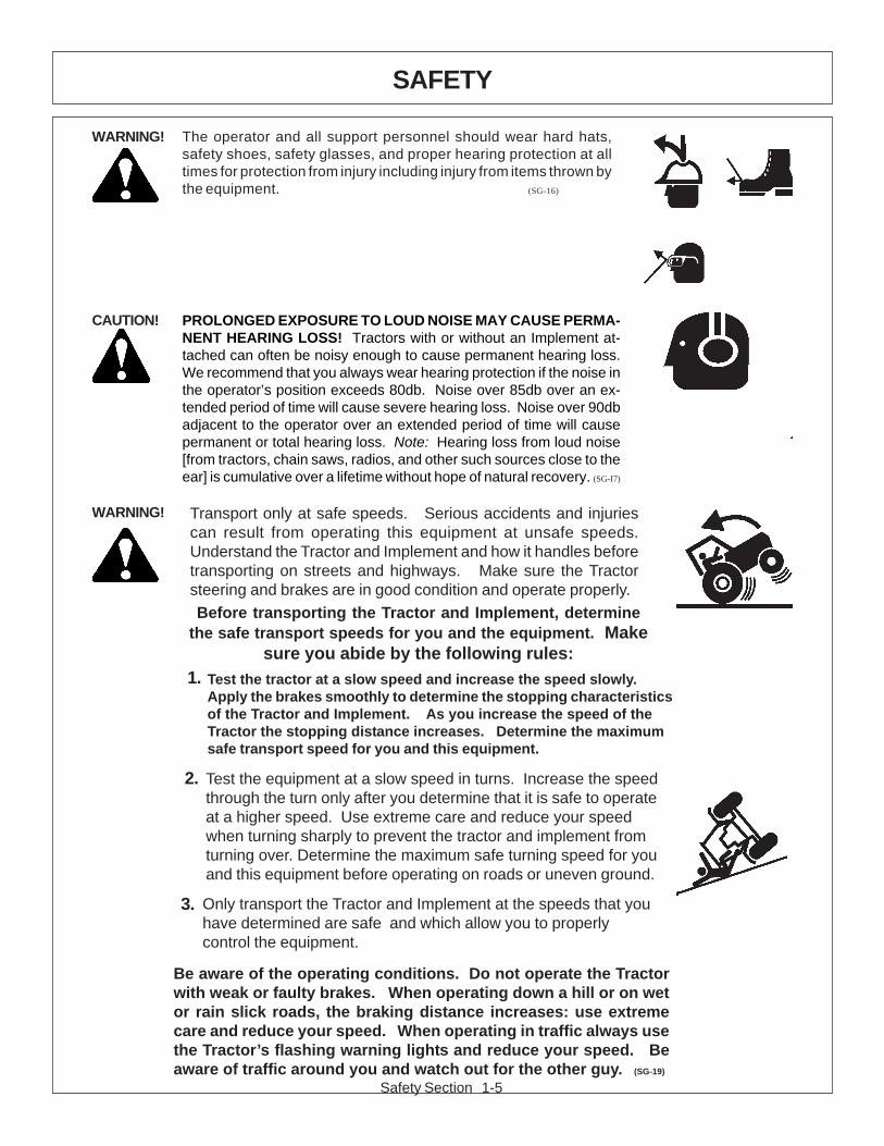
WARNING! Transport only at safe speeds. Serious accidents and injuriescan result from operating this equipment at unsafe speeds.Understand the Tractor and Implement and how it handles beforetransporting on streets and highways. Make sure the Tractorsteering and brakes are in good condition and operate properly.Before transporting the Tractor and Implement, determine
the safe transport speeds for you and the equipment. Makesure you abide by the following rules:
Be aware of the operating conditions. Do not operate the Tractorwith weak or faulty brakes. When operating down a hill or on wetor rain slick roads, the braking distance increases: use extremecare and reduce your speed. When operating in traffic always usethe Tractor’s flashing warning lights and reduce your speed. Beaware of traffic around you and watch out for the other guy. (SG-19)
Test the equipment at a slow speed in turns. Increase the speedthrough the turn only after you determine that it is safe to operateat a higher speed. Use extreme care and reduce your speedwhen turning sharply to prevent the tractor and implement fromturning over. Determine the maximum safe turning speed for youand this equipment before operating on roads or uneven ground.
Only transport the Tractor and Implement at the speeds that youhave determined are safe and which allow you to properlycontrol the equipment.
Test the tractor at a slow speed and increase the speed slowly.Apply the brakes smoothly to determine the stopping characteristicsof the Tractor and Implement. As you increase the speed of theTractor the stopping distance increases. Determine the maximumsafe transport speed for you and this equipment.
2.
1.
3.
CAUTION! PROLONGED EXPOSURE TO LOUD NOISE MAY CAUSE PERMA-NENT HEARING LOSS! Tractors with or without an Implement at-tached can often be noisy enough to cause permanent hearing loss.We recommend that you always wear hearing protection if the noise inthe operator’s position exceeds 80db. Noise over 85db over an ex-tended period of time will cause severe hearing loss. Noise over 90dbadjacent to the operator over an extended period of time will causepermanent or total hearing loss. Note: Hearing loss from loud noise[from tractors, chain saws, radios, and other such sources close to theear] is cumulative over a lifetime without hope of natural recovery. (SG-I7)
WARNING! The operator and all support personnel should wear hard hats,safety shoes, safety glasses, and proper hearing protection at alltimes for protection from injury including injury from items thrown bythe equipment. (SG-16)
Safety Section 1-6
SAFETY
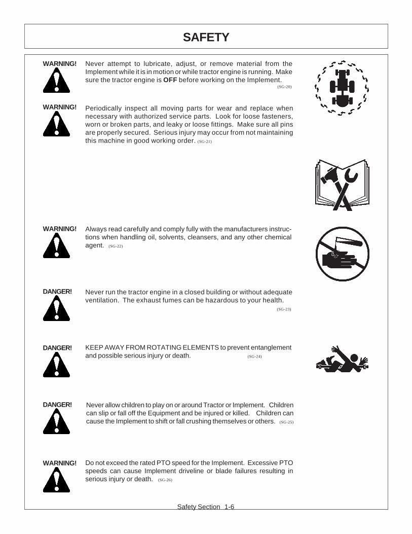
WARNING! Never attempt to lubricate, adjust, or remove material from theImplement while it is in motion or while tractor engine is running. Makesure the tractor engine is OFF before working on the Implement.
(SG-20)
WARNING! Periodically inspect all moving parts for wear and replace whennecessary with authorized service parts. Look for loose fasteners,worn or broken parts, and leaky or loose fittings. Make sure all pinsare properly secured. Serious injury may occur from not maintainingthis machine in good working order. (SG-21)
WARNING! Always read carefully and comply fully with the manufacturers instruc-tions when handling oil, solvents, cleansers, and any other chemicalagent. (SG-22)
DANGER! Never run the tractor engine in a closed building or without adequateventilation. The exhaust fumes can be hazardous to your health.
(SG-23)
DANGER! KEEP AWAY FROM ROTATING ELEMENTS to prevent entanglementand possible serious injury or death. (SG-24)
DANGER! Never allow children to play on or around Tractor or Implement. Childrencan slip or fall off the Equipment and be injured or killed. Children cancause the Implement to shift or fall crushing themselves or others. (SG-25)
WARNING! Do not exceed the rated PTO speed for the Implement. Excessive PTOspeeds can cause Implement driveline or blade failures resulting inserious injury or death. (SG-26)
Safety Section 1-7
SAFETY
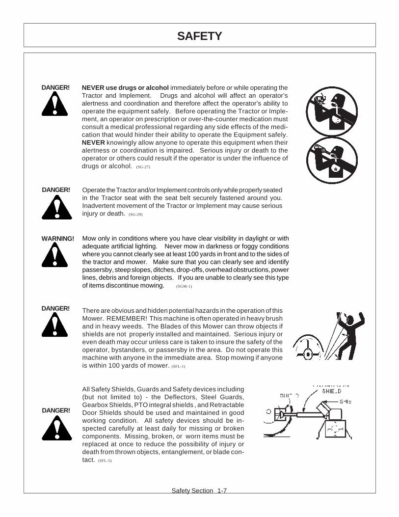
DANGER! NEVER use drugs or alcohol immediately before or while operating theTractor and Implement. Drugs and alcohol will affect an operator’salertness and coordination and therefore affect the operator’s ability tooperate the equipment safely. Before operating the Tractor or Imple-ment, an operator on prescription or over-the-counter medication mustconsult a medical professional regarding any side effects of the medi-cation that would hinder their ability to operate the Equipment safely.NEVER knowingly allow anyone to operate this equipment when theiralertness or coordination is impaired. Serious injury or death to theoperator or others could result if the operator is under the influence ofdrugs or alcohol. (SG-27)
DANGER!
Operate the Tractor and/or Implement controls only while properly seatedin the Tractor seat with the seat belt securely fastened around you.Inadvertent movement of the Tractor or Implement may cause seriousinjury or death. (SG-29)
WARNING! Mow only in conditions where you have clear visibility in daylight or withadequate artificial lighting. Never mow in darkness or foggy conditionswhere you cannot clearly see at least 100 yards in front and to the sides ofthe tractor and mower. Make sure that you can clearly see and identifypassersby, steep slopes, ditches, drop-offs, overhead obstructions, powerlines, debris and foreign objects. If you are unable to clearly see this typeof items discontinue mowing. (SGM-1)
DANGER! There are obvious and hidden potential hazards in the operation of thisMower. REMEMBER! This machine is often operated in heavy brushand in heavy weeds. The Blades of this Mower can throw objects ifshields are not properly installed and maintained. Serious injury oreven death may occur unless care is taken to insure the safety of theoperator, bystanders, or passersby in the area. Do not operate thismachine with anyone in the immediate area. Stop mowing if anyoneis within 100 yards of mower. (SFL-1)
All Safety Shields, Guards and Safety devices including(but not limited to) - the Deflectors, Steel Guards,Gearbox Shields, PTO integral shields , and RetractableDoor Shields should be used and maintained in goodworking condition. All safety devices should be in-spected carefully at least daily for missing or brokencomponents. Missing, broken, or worn items must bereplaced at once to reduce the possibility of injury ordeath from thrown objects, entanglement, or blade con-tact. (SFL-5)
DANGER!

Safety Section 1-8
SAFETY
WARNING!Extreme care should be taken when operating near loose objects suchas gravel, rocks, wire, and other debris. Inspect the area beforemowing. Foreign objects should be removed from the site to preventmachine damage and/or bodily injury or even death. Any objects thatcannot be removed must be clearly marked and carefully avoided bythe operator. Stop mowing immediately if blades strike a foreignobject. Repair all damage and make certain rotor or blade carrier isbalanced before resuming mowing. (SGM-5)
WARNING! Many varied objects, such as wire, cable, rope, or chains, can becomeentangled in the operating parts of the mower head. These items couldthen swing outside the housing at greater velocities than the blades. Sucha situation is extremely hazardous and could result in serious injury oreven death. Inspect the cutting area for such objects before mowing.Remove any like object from the site. Never allow the cutting blades tocontact such items. (SGM-6)
WARNING! Mow at the speed that you can safely operate and control the tractor andmower. Safe mowing speed depends on terrain condition and grass type,density, and height of cut. Normal ground speed range is from 0 to 5 mph.Use slow mowing speeds when operating on or near steep slopes,ditches, drop-offs, overhead obstructions, power lines, or when debris andforeign objects are to be avoided. (SGM-7)
WARNING! Avoid mowing in reverse direction when possible. Check to make surethere are no persons behind the mower and use extreme care whenmowing in reverse. Mow only at a slow ground speed where you can safelyoperate and control the tractor and mower. Never mow an area that youhave not inspected and removed debris or foreign material. (SGM-8)
DANGER! Replace bent or broken blade with new blades. NEVER ATTEMPT TOSTRAIGHTEN OR WELD ON BLADES SINCE THIS WILL LIKELYCRACK OR OTHERWISE DAMAGE THE BLADE WITH SUBSE-QUENT FAILURE AND POSSIBLE SERIOUS INJURY FROM THROWNBLADES. (SGM-10)
WARNING!Do not mow with two machines in the same area except with Cab tractorswith the windows closed. (SGM-11)
DANGER! The rotating parts of this machine have been designed and tested forrugged use. However, the blades could fail upon impact with heavy,solid objects such as metal guard rails and concrete structures. Suchimpact could cause the broken objects to be thrown outward at veryhigh velocities. To reduce the possibility of property damage, seriousinjury, or even death, never allow the cutting blades to contact suchobstacles. (SGM-4)

Safety Section 1-9
SAFETY
DANGER! Flail Mowers are capable under adverse conditions of throwing objectsfor great distances (100 yards or more) and causing serious injury ordeath. Follow safety messages carefully.
STOP MOWING IF PASSERSBY ARE WITHIN 100 YARDS UN-LESS:
-Front and Rear Deflectors are installed and in good, working condition;
-Mower Head is running close to and parallel to the ground without exposed Blades;
-Passersby are outside the existing thrown-object zone;-All areas have been thoroughly inspected and all foreign
material such as rocks, cans, glass, and general debris has been removed.
NOTE: Where there are grass and weeds high enough to hide debristhat could be struck by the blades, the area should be: in-spected and large debris removed, mowed at an intermediateheight, inspected closely with any remaining debris being re-moved, and mowed again at desired final height. (SFL-6)
DANGER! Do not put hands or feet under mower decks. Blade Contact can resultin serious injury or even death. Stay away until all motion has stoppedand the decks are securely blocked up. (SFL-2)
WARNING!Each Rear Wheel must have a minimum of 1,000 pounds contact withthe surface to prevent lateral instability and possible tip-over whichcould result in serious bodily injury or even death. Widen the wheeltread and add weights if needed. Refer to the mounting instructionsor call Customer Service if you need assistance with CouterweightProcedure. (SFL-3)
WARNING!
Do not operate Mower if excessive vibration exists. Shut down PTOand the Tractor engine. Inspect the Mower to determine the sourceof the vibration. If Mower blades are missing or damaged replacethem immediately. Do not operate the mower until the blades havebeen replaced and the Mower operates smoothly. Operating theMower with excessive vibration can result in component failure andbroken objects to be thrown outward at very high velocities. To reducethe possibility of property damage, serious injury, or even death, neverallow the Mower to be operated with blades missing. (SFL-4)
WARNING!
Be particularly careful when transporting the Implement with the Tractor.Turn curves or go up hills only at a low speed and using a gradualsteering angle. Rear mounted implements move the center of gravity tothe rear and remove weight from the front wheels. Make certain, byadding front ballast, that at least 20% of the tractor’s weight is on thefront wheels to prevent rearing up, loss of steering control or Tractor tip-over. Slow down on rough or uneven surfaces to prevent loss ofsteering control which could result in property damage or possible injury.Do not transport unless 3-Point lift lever is fully raised and in the latchedtransport position. Dropping implement in transport can cause seriousdamage to the tractor and/or Implement and possibly cause the operatoror others to be injured or killed. (S3PT-2)

Safety Section 1-10
SAFETY
DANGER! Always disconnect the main PTO Driveline from the Tractor beforeperforming service on the Mower. Never work on the Mower with thetractor PTO driveline connected and running. Blades or Drivelines couldturn without warning and cause immediate entanglement, injury or death.(SRM-3)
WARNING!Do not let the Blades turn when the Mower Deck is raised for anyreason, including clearance or for turning. Raising the Mowerdeck exposes the Cutting Blades which creates a potentiallyserious hazard and could cause serious injury or even death fromobjects thrown from the Blades. (SRM-7)
WARNING!Never leave Tractor and Implement unattended while the implement is inthe lifted position. Accidental operation of lifting lever or a hydraulic failuremay cause sudden drop of unit with injury or death by crushing. Toproperly park the implement when disconnecting it from the tractor, lowerthe stand and put the retaining pin securely in place, or put a securesupport under the A-Frame. Lower the implement carefully to the ground.Do not put hands or feet under lifted components. (SPT-1)
DANGER! Make sure the PTO shield, integral driveline shields, and input shields areis installed when using PTO-driven equipment. Always replace anyshield if it is damaged or missing. (S3PT-8)
WARNING! Relieve hydraulic pressure prior to doing any maintenance or repair workon the Implement. Place the Implement on the ground or securelyblocked up, disengage the PTO, and turn off the tractor engine. Pushand pull the Remote Cylinder lever in and out several times prior tostarting any maintenance or repair work. (S3PT-9)
WARNING! Use extreme care when lowering or unfolding the implement’s wings.Make sure no bystanders are close by or underneath the wings. Allowample clearance around the implement when folding or unfolding thewings. Use extreme caution around buildings or overhead power lines.
(S3PT-5)
DANGER!When the Wings are folded for transport, the center of gravity is raisedand the possibility of overturn is increased. Drive slowly and useextremecaution when turning on hillsides. Overturning the Implementcould cause the Implement to overturn the Tractor and vice versa resultingin serious injury or even death. Never fold wings on a hillside...theImplement may overturn. (STI-2)
DANGER!DO NOT allow any person under a folded wing unless wing is securelylocked up or supported. DO NOT approach the Implement unless theTractor is turned off and all motion has ceased. Never work under theframe work, or any lifted component unless the implement is securelysupported or blocked up. A sudden or inadvertent fall by any of thesecomponents could cause serious injury or even death. (STI-3)

Safety Section 1-11
SAFETY
WARNING!
In addition to the design and configuration of this Implement, including Safety Signs and SafetyEquipment, hazard control and accident prevention are dependent upon the awareness,concern, prudence, and proper training of personnel involved in the operation, transport,maintenance, and storage of the machine. Refer also to Safety Messages and operationinstruction in each of the appropriate sections of the Tractor and Equipment Manuals. Payclose attention to the Safety Signs affixed to the Tractor and Equipment. (SG-18)
Tiger mowers use balanced and matched system components for blade carriers, blades, cutter-shafts, knives, knife hangers, rollers, drive-train components and bearings. These parts are made andtested to Tiger specifications. Non-genuine “will fit” parts do not consistently meet these specifications.The use of “will fit” parts may reduce mower performance, void mower warranties and present a safetyhazard. Use genuine Tiger mower parts for economy and safety.
SEE YOUR DEALER
Engine Exhaust, some of its constituents, and certain components contain or emitchemicals known to the state of California to cause cancer and birth or otherreproductive harm.
WARNING!Battery posts, terminals and related accessories contain lead and lead compounds,chemicals known to the state of California to cause cancer and birth or otherreproductive harm. Wash hands after handling!
WARNING! The rotating parts of this machine continue to rotate even after the PTO has been turnedoff. The operator should remain in his seat for 60 seconds after the brake has been set,the PTO disengaged, the tractor turned off, and all evidence of rotation has ceased.(3PT-10)
“Wait a minute...Save a life!”
DANGER! The flail cutter shaft is designed for standard rotation (samerotation as the tractor wheels during forward travel). Never operate thecutter shaft in the reverse rotation. Operating this mower in reverserotation may cause objects to be thrown out the front of the mowerhead.

Safety Section 1-12
SAFETY
24028 MOWER DECK
22839 MOWER DECK
21405 MOWER DECK
22840 INSIDE OF CAB
PART NO.LOCATION

Safety Section 1-13
SAFETY
42350 MOWER DECK
33743 INSIDE OF CAB
10” x 5.5” 31522 MOWER DECK18.25” x10” 31523 HYDRAULIC TANK
PART NO.LOCATION

Safety Section 1-14
SAFETY
6T3217 MOWER DECK
42399 MOWER DECK
6T3219 INSIDE OF CAB
6T3220FRONT PUMP MOUNT
PART NO.LOCATION
42400 MOWER DECK
Safety Section 1-15
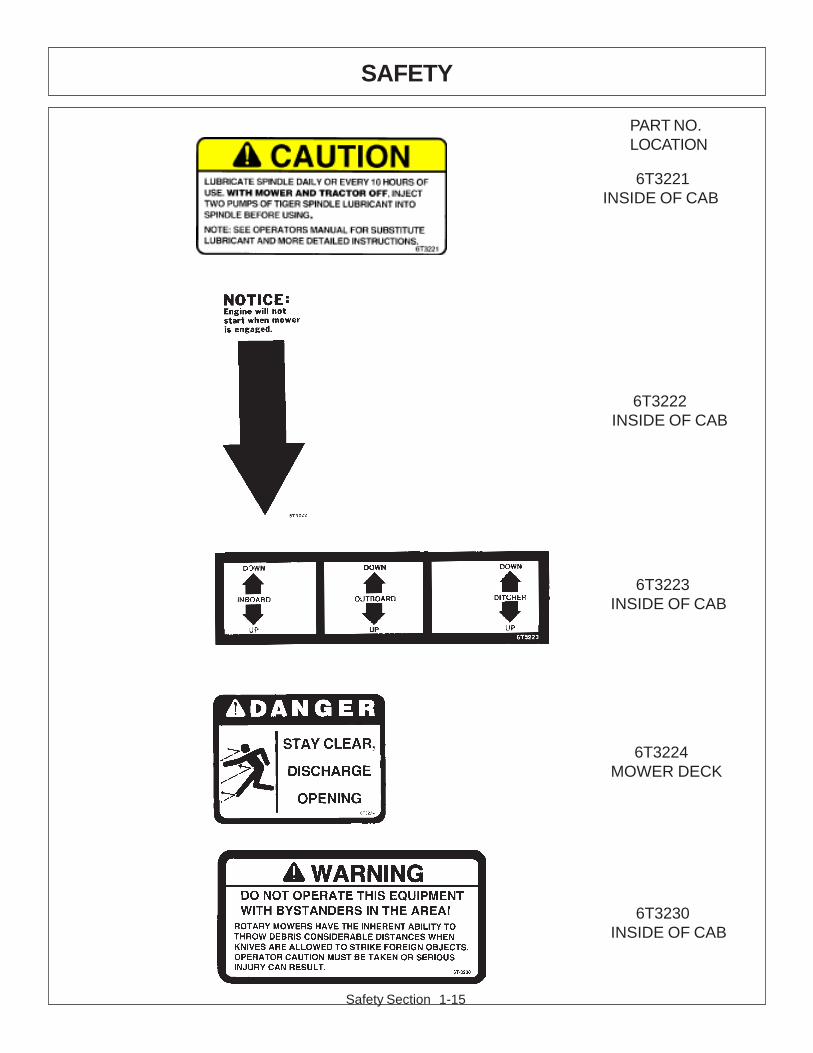
SAFETY
6T3223 INSIDE OF CAB
6T3224 MOWER DECK
6T3221 INSIDE OF CAB
6T3222 INSIDE OF CAB
PART NO.LOCATION
6T3230 INSIDE OF CAB
Safety Section 1-16
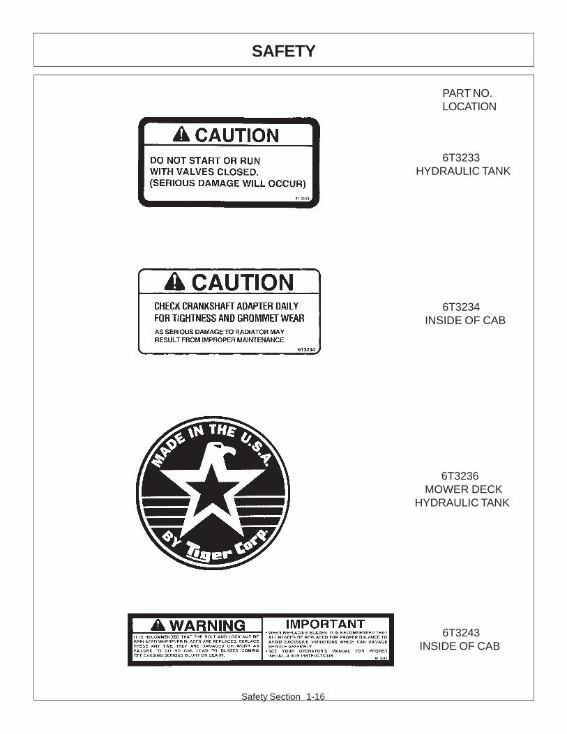
SAFETY
6T3243 INSIDE OF CAB
6T3236 MOWER DECK HYDRAULIC TANK
6T3233 HYDRAULIC TANK
6T3234 INSIDE OF CAB
PART NO.LOCATION
Safety Section 1-17
SAFETY
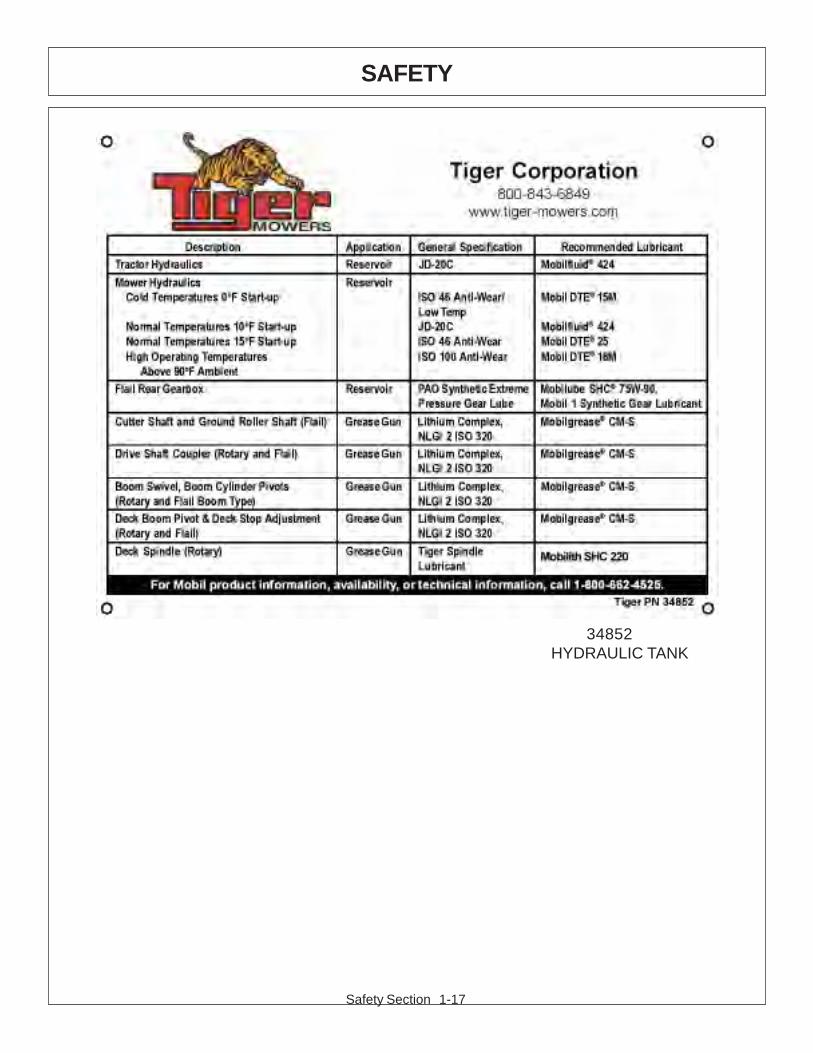
34852 HYDRAULIC TANK

Safety Section 1-18
SAFETY
ITEM PART NO. QTY. DESCRIPTION
50023 AVAIL MANUAL CANISTER COMPLETE1 00776031 1 ROUND MANUAL CANISTER
33997 1 DECAL, SHEET, MANUAL CANISTER2 * DECAL3 * DECAL4 * DECAL5 * AVAIL SPECIFIC PRODUCT MANUAL6 33753 1 E M I SAFETY MANUAL7 34296 1 FRONT ADHESIVE PAD8 34297 1 REAR ADHESIVE PAD9 6T1823 4 ZIP TIE 14” LONG
NOTE:The manual canister can be bolted, zip tied or adhered to a variety ofsurfaces. Locate a protected area within the view of the operator. Thenselect an installation method and attach the canister. CAUTION - AVOIDDRILLING HOLES INTO UNKNOWN AREAS, wires and other parts maybe located behind these areas. When adhering the canister to a surface,thoroughly clean that surface before installing the canister.

Safety Section 1-19
SAFETY
This section is intended to explain in broad terms the concept and effect of federal laws and regulationsconcerning employer and employee equipment operators. This section is not intended as a legalinterpretation of the law and should not be considered as such.
Employer-Employee Operator RegulationsU.S. Public Law 91-596 (The Williams-Steiger Occupational and Health Act of 1970) OSHA
This Act Seeks:“...to assure so far as possible every working man and woman in the nation safe andhealthful working conditions and to preserve our human resources...”
DUTIESSec. 5 (a) Each employer-(1) shall furnish to each of his employees employment and a place of employment whichare free from recognized hazards that are causing or are likely to cause death or seriousphysical harm to his employees;(2) shall comply with occupational safety and health standards promulgated under thisAct.(b) Each employee shall comply with occupational safety and health standards and allrules, regulations and orders issued pursuant to this Act which are applicable to hisown actions and conduct.
OSHA RegulationsOSHA regulations state in part: “At the time of initial assignment and at least annuallythereafter, the employer shall instruct every employee in the safe operation and servicingof all equipment with which the employee is, or will be involved.”
Employer Responsibilities:To ensure employee safety during Tractor and Implement operation, it is the employer’s responsibilityto:
1. Train the employee in the proper and safe operation of the Tractor and Implement.
2. Require that the employee read and fully understand the Tractor and Implement Operator’s manual.
3. Permit only qualified and properly trained employees to operate the Tractor and Implement.
4. Maintain the Tractor and Implement in a safe operational condition and maintain all shields andguards on the equipment.
5. Ensure the Tractor is equipped with a functional ROPS and seat belt and require that the employeeoperator securely fasten the safety belt and operate with the ROPS in the raised position at alltimes.
6. Forbid the employee operator to carry additional riders on the Tractor or Implement.
7. Provide the required tools to maintain the Tractor and Implement in a good safe working conditionand provide the necessary support devices to secure the equipment safely while performing repairsand service.
Child Labor Under 16 Years of AgeSome regulations specify that no one under the age of 16 may operate power machinery. It is yourresponsibility to know what these regulations are in your own area or situation. (Refer to U.S. Dept. ofLabor, Employment Standard Administration, Wage & Home Division, Child Labor Bulletin #102.)
FEDERAL LAWS AND REGULATIONS

Safety Section 1-20
SAFETY

ASSEMBLYSECTION
Assembly Section 2-1
Assembly Section 2-2
ASSEMBLY
Before attempting to mount or service your Tiger mower, it is important toread and understand all of the information in the Safety section of this manual.
Check complete shipment list against the packing list to make sure there are noshortages. Make certain the tractor model is the appropriate one for the mowerreceived!
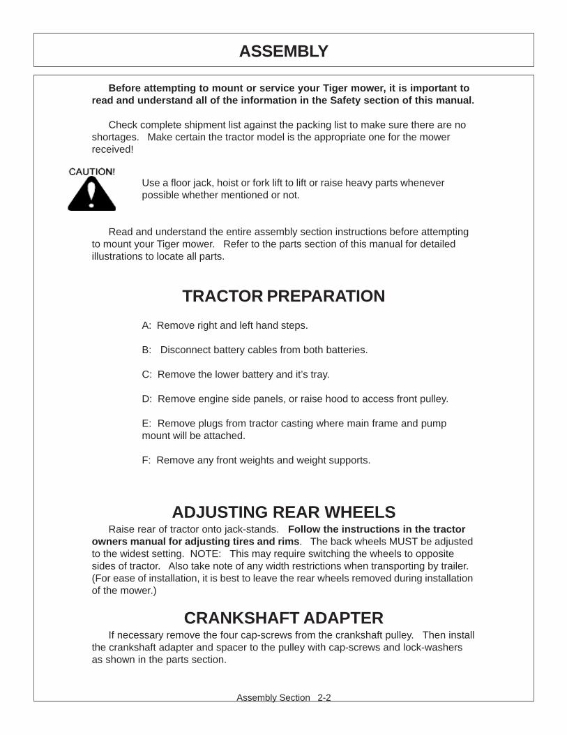
Use a floor jack, hoist or fork lift to lift or raise heavy parts wheneverpossible whether mentioned or not.
Read and understand the entire assembly section instructions before attemptingto mount your Tiger mower. Refer to the parts section of this manual for detailedillustrations to locate all parts.
TRACTOR PREPARATION
A: Remove right and left hand steps.
B: Disconnect battery cables from both batteries.
C: Remove the lower battery and it’s tray.
D: Remove engine side panels, or raise hood to access front pulley.
E: Remove plugs from tractor casting where main frame and pumpmount will be attached.
F: Remove any front weights and weight supports.
ADJUSTING REAR WHEELSRaise rear of tractor onto jack-stands. Follow the instructions in the tractor
owners manual for adjusting tires and rims. The back wheels MUST be adjustedto the widest setting. NOTE: This may require switching the wheels to oppositesides of tractor. Also take note of any width restrictions when transporting by trailer.(For ease of installation, it is best to leave the rear wheels removed during installationof the mower.)
CRANKSHAFT ADAPTERIf necessary remove the four cap-screws from the crankshaft pulley. Then install
the crankshaft adapter and spacer to the pulley with cap-screws and lock-washersas shown in the parts section.
Assembly Section 2-3
ASSEMBLY
MODIFICATION OF FRONT CASTINGHole in front support / casting is not provided for an auxiliary pump and drive shaft
to be mounted and driven off of the front engine crank.Two methods have been developed to rework the front support to add passage
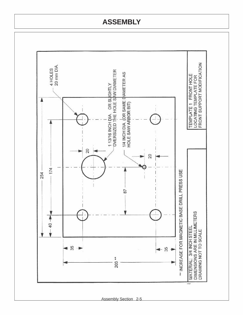
holes for a drive shaft without removal of the front support from the tractor. Methodone requires the use of a right angle drill, and method two requires a magnetic basedrill. Method two also requires modification of two 1-1/2” deep hole saws byremoving the teeth from one saw, cutting the cap off of a second and welding the twotogether to achieve a 3” cutting depth. Method two is suggested for dealersexpecting to rework several tractors. Diagrams of two templates follow theseinstructions to properly locate the holes. These templates must be produced andused accurately to locate and drill the holes. Note: If using method 2 with amagnetic base drill, the template must be increased to approximately 20” long tosupport drill base.
METHOD 1:Required Materials: 1/2" drive right angle drill
1 3/4" hole saw for metals1/4" drill bitGuide templates 1 and 23/8” x 1” Capscrews, flat & lockwashers – qty. 4 ea.
1. Locally produce the two guide plates.2. Fasten template 1 to the front, top two center holes of the front support so the ¼”hole of the template is located closest to the top. Attach the template, using two20mm x 50mm x 2.5mm bolts. This will locate the hole 3-25/32” from the top edgeof the front web and in line with the center of the crankshaft.3. Drill a ¼” pilot hole completely through the front web of the casting, usingtemplate 1 as a guide.4. Reinstall template 1 with the 1-13/16” guide hole closest to the top and centeredover the ¼” pilot hole.5. Bore the 1-3/4” hole, using the hole saw bit and template 1 as a guide to maintaina straight hole. Bore from the front side, as deep as the hole saw will allow.6. Finish boring the hole in the front web from the back side, using the right angledrill. Use the ¼” pilot hole as a guide. Care must be taken to start and maintain astraight bore.7. Remove the sheet metal cover attached to the rear web. In its place, attachtemplate 2, using the same 8mm x 16mm bolts that held the metal cover in place.This will locate the hole 2-11/16” from the top edge of the rear web and in line with thecenter of the crankshaft.8. Drill a ¼” hole through the rear web, using template 2 as a guide.9. Remove template 2 and bore a 1-3/4” hole, using the holes saw and right angledrill.10. File edges of the holes to remove any sharp corners and paint as required.11. Install the new battery stands using the original hardware. Install the lowerbattery tray onto the stands, using 3/8” x 1” capscrews, flat and lockwashers.12. Install the lower battery ground cable. It will be necessary to reverse theconnections of the ground cable to the batteries, as the cable will now be too short toreach the original front support grounding location. The new ground point will be themounting bolt for the top battery tray. Be sure to remove paint between upper traybracket and mounting surface to promote a solid ground location.
Assembly Section 2-4
ASSEMBLY
METHOD 2:Required Materials: Magnetic base drill
16” – 18” bit extension1-3/4” hole saw for metals – qty. 2 (modified)1/4" drill bit – 16” x 18” longGuide template 1 – increase length to fit drill baseGuide templste 23/8” x 1” capscrews, flat & lockwashers – qty. 4 ea.
1. Locally produce the two guide templates. The length of template 1 will need to beincreased from 8” to approximately 20” or as required for the magnetic drill base.2. Fasten template 1 to the front, top two center holes of the front support so the ¼”hole of the template is located closest to the top. Attach the template, using two20mm x 50mm x 2.5mm bolts. This will locate the hole 3-25/32” from the top edgeof the front web and in line with the center of the crankshaft.3. Remove the sheet metal cover attached to the rear web. In its place, attachtemplate2, using the same two 8mm x 16mm bolts that held the metal cover in place.This will locate the hole 2 11/16” from the top edge of the rear web and in line with thecenter of the crankshaft.4. Drill a ¼” pilot hole completely through the front and rear web of the casting usingthe templates as a guide for the 16” – 18” long bit. The use of the second templateensures the location of the rear hole.5. Reinstall template 1 with the 1-13/16” guide hole closest to the top and centeredover the ¼” pilot hole. Remove template 2.6. Bore the 1-3/4” hole through the front web using the modified hole saw andtemplate 1 as a guide to maintain a straight hole.7. Install the 16” – 18” long bit into the drill and install the modified hole saw onto thebit.8. Using the ¼” pilot hole, drill the hole in the rear web.9. File the edges of the holes to remove any sharp corners, and paint as required.10. Install the new battery stands using the original hardware. Install the lowerbattery tray onto the stands, using 3/8” x 1” capscrews, flat and lockwashers.11. Install the lower battery ground cable. It will be necessary to reverse theconnections of the ground cable to the batteries, as the cable will now be too short toreach the original front support grounding location. The new ground point will be themounting bolt for the top battery tray. Be sure to remove paint between upper traybracket and mounting surface to promote a solid ground location.
The following two pages show drawings of the templates to be produced. Notethat they are not to scale. Template 1 is to be produced from ¾” steel. Template 2is to be produced from strip steel as needed.
Assembly Section 2-5
ASSEMBLY

Assembly Section 2-6
ASSEMBLY
Assembly Section 2-7
ASSEMBLY
CABLE CONTROL LEVER STAND (cab units)Position the stand on the floor of the cab in front and to the right of the operator.
Be sure that the location of the stand will allow clearance between the cable controlhandles and all existing interior levers, etc. Also be sure to allow room for the mowerswitch box to be mounted with the control handles. After the stand is properlypositioned, check for any obstructions under the cab before drilling holes.
Drill 3 holes to match control bracket and secure with cap-screws and nylocknuts noted in parts section.
Cut a 2 ¼” hole in the fender from inside the cab. This hole is to be locatedapproximately 4” up from floor, and 5” from the metal edge by the right door. Installtrim lock around the metal edges of the hole, then route the cables through the hole.Next, wrap the cables with the 6” split hose at the point they pass through the hole,and secure with zip-ties.
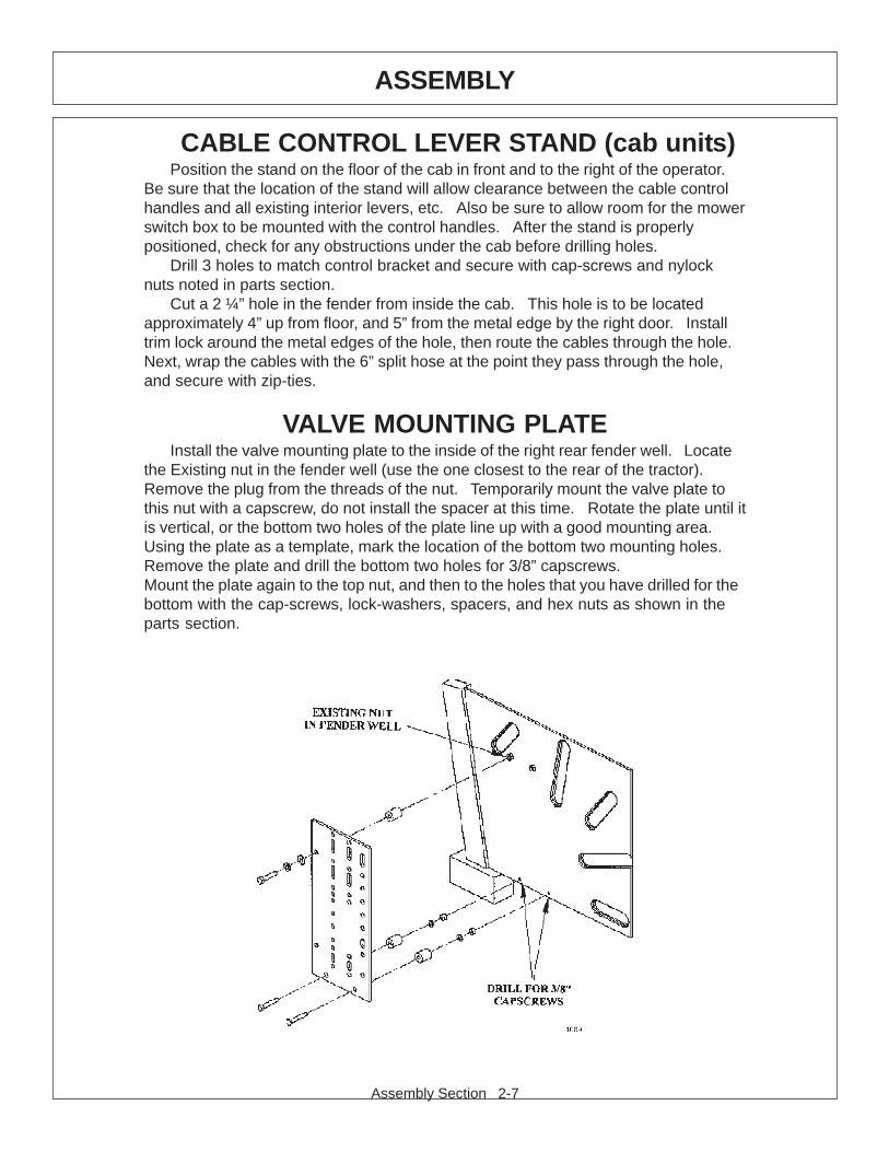
VALVE MOUNTING PLATEInstall the valve mounting plate to the inside of the right rear fender well. Locate
the Existing nut in the fender well (use the one closest to the rear of the tractor).Remove the plug from the threads of the nut. Temporarily mount the valve plate tothis nut with a capscrew, do not install the spacer at this time. Rotate the plate until itis vertical, or the bottom two holes of the plate line up with a good mounting area.Using the plate as a template, mark the location of the bottom two mounting holes.Remove the plate and drill the bottom two holes for 3/8” capscrews.Mount the plate again to the top nut, and then to the holes that you have drilled for thebottom with the cap-screws, lock-washers, spacers, and hex nuts as shown in theparts section.
Assembly Section 2-8
ASSEMBLY
PLY-CARBONATE SAFETY WINDOW - OPT.NOTE: This should be done before mounting the main frame. Remove the right
side cab windows that match the poly windows provided. Installing a boom mowerrequires that all of the right side windows be replaced.
Peel back the protective paper from the area around the window that will contactthe frame. Install the outside trim to the right rear window. Position metal supporttube to the outside, front edge of the poly window, just inside of the moulding andclamp together. Next drill 3 holes for 3/16” pop rivets through the window to matchthe 3 holes in the metal tube.
Pop rivet tube into position onto poly window.Remove weather strip from factory window and replace onto poly window.
(Some newer tractors must use trim supplied in the kit. Affix ends of trim seal with 1/8” pop rivets provided).
Install the poly window into place where factory window was removed (upper rightrear first).
Last, install the factory right door window poly and secure with 19 pop rivetsevenly spaced. Replace the door onto the tractor.
MAIN FRAME MOUNTINGRaise front of tractor as needed and slide the main frame under tractor from right
hand side. With an overhead hoist and / or jack-stands, raise the frame up to thecorrectly matching mounting holes. Install cap-screws and all other hardware asshown in main frame parts section. Remove the cap-screws one at a time andapply a thread locking agent, then reinsert the cap-screws and tighten / torque tovalues noted in the torque chart located in the maintenance section of this manual.
FRONT PUMP MOUNTINGInstall the pump mounting bracket on the front of the tractor with cap-screws and
lock-washers as shown in the parts section illustration. DO NOT tighten fasteners atthis time.
Slide the pump drive shaft into the crankshaft adapter. The end with the shortersplines should be inserted into the adapter (if applicable). Slide the splined driveshaft coupler onto the pump drive shaft. Install the pump onto the mounting bracket.NOTE: the shaft is offset to one direction, the pump should be installed with theoffset side on top. Install hardware for securing pump to the pump mount, DO NOTtighten.
Align pump so that splined coupling can be moved back and forth by hand.Tighten pump mounting bolts in succession rechecking for spline couplingmovement. Remove the pump mounting bracket bolts one at a time and apply atread locking agent. Tighten these bolts in succession, again checking for freemovement in the drive shaft. After all bolts are torqued, the end play on the driveshaft should be 1/16” to 1/8”, and coupler should move freely with hand pressure. Ifend play is less than 1/16”, grind the end of the shaft to achieve the proper end play.If there is more than 1/4" of end play, return the shaft with specifications for a longershaft.
CAUTION: DO NOT START THE TRACTOR UNTIL ALL HOSES AREATTACHED AND TANK IS FILLED WITH PROPER OIL! STARTING AT THISTIME WILL CAUSE SERIOUS DAMAGE TO THE PUMP.
Assembly Section 2-9
ASSEMBLY
SECTIONAL VALVE MOUNTING W/CABRefer to the boom lift valve assembly for hardware an placement of all related
parts.
SECTIONAL VALVE MOUNTING WO/CABRefer to the boom lift valve assembly for hardware and location of components.
First, attach control valve stand to the top of the main frame mast with cap-screws,lock-washers and hex nuts. NOTE: The mounting plate should face the rear of thetractor.
Attach the 4-spool control valve to the stand using the hardware noted in the partssection. One cap-screw must be used to secure the switch box to the under side ofthe valve stand.
SWITCH MOUNTINGRefer to the parts section for wiring diagrams. Remove right side cowl panel,
tach panel, and hour meter panel for access to the wires.Route the red wire from the switch box to the bare electrical plug in the fuse box,
or other un-used “keyed” hot wire. NOTE: +12 VOLTS ELECTRICAL POWERMUST BE TAKEN FROM A SOURCE LOCATION WHERE IT IS LIVE ONLYWHEN THE IGNITION SWITCH IS IN THE “ON” POSITION. THIS WIRE MUSTBE FUSED AT THE SOURCE LOCATION.
Drill a ½” hole in the 9” X 5” right side panel to route the green safety switch wires,and white wire to be connected to the hydraulic solenoid valve.
The switch box is to be secured to the operators side of the control handles, orvalve stand.
The green wires will connect to the neutral safety switch, located on the back ofthe ignition switch, under the cowl panel.
TEMPERATURE GAUGE MOUNTING(OPTIONAL)
Mount the temperature gauge where it is clearly visible to the operator. Attach thegreen ( - ) wire from the negative post on the gauge to a grounded bolt on the tractorframe. Remove paint if needed to make a good ground.
Remove the pipe plug from the side of the hydraulic reservoir, and install thetemperature sensor using tread sealing tape.Run the white wire from the ( S ) sensor post of the gauge to the temperature sensoron the hydraulic reservoir tank.
Assembly Section 2-10
ASSEMBLY

Assembly Section 2-11
ASSEMBLY
GENERAL HOSE INSTALLATIONRefer to the parts section for detailed information about hoses and fittings for this
application.When mounting the suction hose between the pump and the tank, the stainless
steel bands that are provided must be used. CAUTION: DO NOT use regular hoseclamps for this purpose.
For protection of hoses in contact with metal edges, wrap hoses with spit hosesections and fasten with hose clamps or zip ties as needed.
INSTALLING O-RING FITTINGSInstalling straight, 45 degree and 90 degree O-rings requires that the O-ring and
washer (A) be up against the swivel body (B). Insert the swivel and turn in until theswivel is pointed in the right direction and the O-ring contact is made. Hold swivel inset direction with a wrench and turn the O-ring nut away from the swivel body andcarefully tighten.
INSTALLING NATIONAL PIPE FITTINGSWhenever installing a pipe fitting, wrap the threads clockwise (looking at the end)
with teflon tape. In this way, the tape will be tightened when installed. NOTE: It isnot necessary to tape O-ring fittings, or those installed in swivels.
HYDRAULIC TANK INSTALLATIONInstall all fittings and tubes into tank and tank filter as shown in parts section
illustration. Insert tank sight glass into front side of the tank. Install thetemperature sensor or pipe plug into the side of the tank.
Place the tank in the mounting bracket on the main fame with fittings towardtractor and filter toward the cab.
Secure the tank in the mounting bracket with the tank strap and nylock nuts.Install the filter gauge into the filter housing so that it points to the rear of the
tractor and is clearly visible to the operator.Locate the tank breather and reducer bushing (bushing may be already
installed in the tank along with many of the for-mentioned parts). These will beinstalled after tank is filled.
Assembly Section 2-12
ASSEMBLY
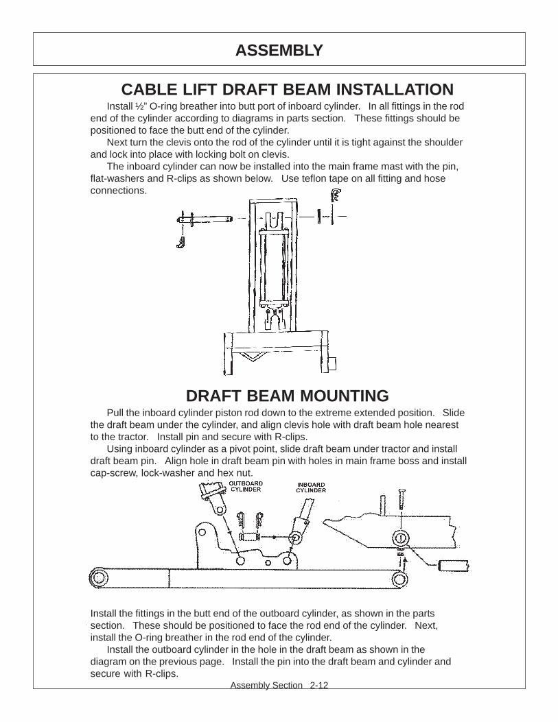
CABLE LIFT DRAFT BEAM INSTALLATIONInstall ½” O-ring breather into butt port of inboard cylinder. In all fittings in the rod
end of the cylinder according to diagrams in parts section. These fittings should bepositioned to face the butt end of the cylinder.
Next turn the clevis onto the rod of the cylinder until it is tight against the shoulderand lock into place with locking bolt on clevis.
The inboard cylinder can now be installed into the main frame mast with the pin,flat-washers and R-clips as shown below. Use teflon tape on all fitting and hoseconnections.
DRAFT BEAM MOUNTINGPull the inboard cylinder piston rod down to the extreme extended position. Slide
the draft beam under the cylinder, and align clevis hole with draft beam hole nearestto the tractor. Install pin and secure with R-clips.
Using inboard cylinder as a pivot point, slide draft beam under tractor and installdraft beam pin. Align hole in draft beam pin with holes in main frame boss and installcap-screw, lock-washer and hex nut.
Install the fittings in the butt end of the outboard cylinder, as shown in the partssection. These should be positioned to face the rod end of the cylinder. Next,install the O-ring breather in the rod end of the cylinder.
Install the outboard cylinder in the hole in the draft beam as shown in thediagram on the previous page. Install the pin into the draft beam and cylinder andsecure with R-clips.

Assembly Section 2-13
ASSEMBLY
TRAVEL LOCK MOUNTINGInstall the travel lock bracket with pin and clip on the draft beam. Slide the draft
beam and align the travel lock bracket hole with the mounting hole on the main frame.Install the capscrew, lockwasher and hex nut as shown in the picture.
Raise the deck/flail to it’s upright position (Deck ear touches to stop bolt as shownin the picture). Drill a 13/16” hole to the deck/flail ear through the draft beam as shownbelow. Insert the supplied pin and clip through the hole.

Assembly Section 2-14
ASSEMBLY
LIFT CONTROL FEEDLINESHose lengths will vary between tractor applications such as cab and non-cab
units. See the parts section that pertains to your tractor for hose applications.Install a hose from the bottom or inner valve port (in fender well for cab units, on
stand for non-cab units) to the restrictor on the inboard cylinder gland.Install a hose form the upper or outer valve port to the restrictor on the outboard
cylinder butt. Use teflon tape on all fitting and hose connections.
DECK / MOTOR FEEDLINEInstall the 1” hose with the 180 degree flange on the front side of the motor to the
top of the solenoid valve. Secure to motor with flange kit, and install swivel fitting onthe other end. Install the other 1” hose with the 60 degree flange on the back side ofthe motor to the bottom of the solenoid valve.
Install split hoses around hydraulic hoses where they contact sharp edges, or anyother edges that may rub hoses.
Be sure that all grease zerks are installed in the draft beam pin bosses. Greaseall areas of the draft beam according to the instructions in the maintenance section.
Re-check all fittings for tightness and be sure teflon tape has been used at allconnections.
Fill hydraulic tank with fluid as recommended in the maintenance section. BESURE TO OPEN THE BALL VALVES. Start the tractor and operate the inboardcylinder through the entire stroke and the outboard cylinder through the bottom ¾stroke repeatedly to clear the lines of air. DO NOT run outboard cylinder out tofull stroke until turnbuckle has been adjusted!
Check for oil leaks at all fittings and connections using a piece of paper orcardboard. DO NOT USE HANDS TO CHECK FOR FLUID LEAKS!
Raise the tree point hitch and check the tractor internal hydraulics, fill to properlevel if needed.
Assembly Section 2-15
ASSEMBLY
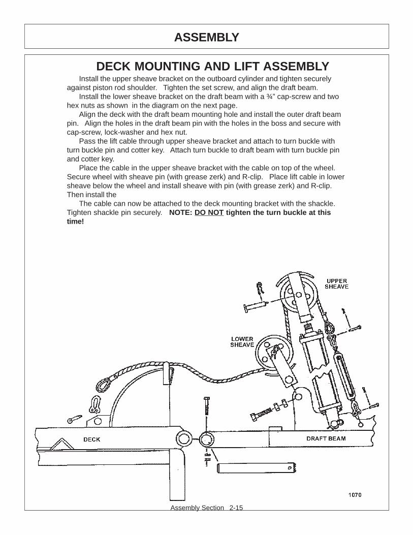
DECK MOUNTING AND LIFT ASSEMBLYInstall the upper sheave bracket on the outboard cylinder and tighten securely
against piston rod shoulder. Tighten the set screw, and align the draft beam.Install the lower sheave bracket on the draft beam with a ¾” cap-screw and two
hex nuts as shown in the diagram on the next page.Align the deck with the draft beam mounting hole and install the outer draft beam
pin. Align the holes in the draft beam pin with the holes in the boss and secure withcap-screw, lock-washer and hex nut.
Pass the lift cable through upper sheave bracket and attach to turn buckle withturn buckle pin and cotter key. Attach turn buckle to draft beam with turn buckle pinand cotter key.
Place the cable in the upper sheave bracket with the cable on top of the wheel.Secure wheel with sheave pin (with grease zerk) and R-clip. Place lift cable in lowersheave below the wheel and install sheave with pin (with grease zerk) and R-clip.Then install the
The cable can now be attached to the deck mounting bracket with the shackle.Tighten shackle pin securely. NOTE: DO NOT tighten the turn buckle at thistime!
Assembly Section 2-16
ASSEMBLY
TURNBUCKLE ADJUSTMENTExtend the outboard cylinder until the deck touches the stop on the draft beam.
Hold the deck in this position to adjust the lift cable tension. Adjust turn buckle untilcable is tight.
Lower and raise the deck to check adjustment. The mower deck should reachit’s stop on the draft beam at the same time the outboard cylinder reaches it’sextreme extended position.
Finally tighten the turn buckle lock nuts securely. It will be necessary to readjustthe turn buckle after the cable has stretched from use.
FINAL PREPARATION FOR OPERATIONPlace operators safety and operation decals on the steering column and side
counsel where they are clearly visible to the operator. These decals should beunderstood by each operator of the machine in conjunction with the safety andoperation section of this book. The decals are to remain in good condition as areminder to the operator, and should be replaced if damaged.
Double check that all pivot points have been greased. Secure all hoses togetherwith zip ties and wrap with split hose sections where friction may occur on the hose.
BEFORE starting or operating the tractor you must read and understandthe safety and operation sections of this manual completely.
Before operating the mower, the cutter head and draft beam should be slowlymoved throughout the full range of motion. Watch for any condition that would causepinching or excess stress on the hoses. The steering and front axle travel shouldalso be carefully moved through their full range of motion. If any condition occurs inwhich the hoses contact the tires, the steering and / or front axle travel may need tobe limited as described in the tractor operators manual. This should also be done ifthe tires rub, or are extremely close to any other part of the mower such as thehydraulic tank or draft beam. This may include adding shims, or adjusting stop boltsin the tractor front to solve the problem. While checking motion, you should alsocheck that the control circuits are connected according to the operators decal for thevalve handles.
MOWER TESTINGTake the tractor to a place free of loose objects on the ground. Operate the
cylinders through their full range of motion again, to clear the lines of air. Follow theinstructions in the operation section to operate the mower. Vibration of the mowershould be minimal at all times. After a 5 minute test run, the knife bolts should beretorqued and once again after the first few hours of operation.
If any parts of this assembly section, or any other section of thismanual are not clearly understood you must contact your dealer or theaddress on the front of this manual for assistance!

Assembly Section 2-17
ASSEMBLY
DRAFT BEAM MOUNTINGPull the inboard cylinder piston rod down to the extreme extended position. Slide
the draft beam under the cylinder, and align clevis hole with draft beam hole nearestto the tractor. Install pin and secure with R-clips.
Using inboard cylinder as a pivot point, slide draft beam under tractor and installdraft beam pin. Align hole in draft beam pin with holes in main frame boss and installcap-screw, lock-washer and hex nut.
COMBO LIFT DRAFT BEAM INSTALLATIONInstall ½” O-ring breather into butt port of inboard cylinder. In all fittings in the rod
end of the cylinder according to diagrams in parts section. These fittings should bepositioned to face the butt end of the cylinder.
Next turn the clevis onto the rod of the cylinder until it is tight against the shoulderand lock into place with locking bolt on clevis.
The inboard cylinder can now be installed into the main frame mast with the pin,flat-washers and R-clips as shown below. Use teflon tape on all fitting and hoseconnections.
Install all fittings in the outboard cylinder and adjust to point towards the butt endof the cylinder. Attach the hoses as specified in the parts book. Slide the cylinderinto the draft beam from the outside of the draft beam and attach cylinder to the draftbeam with clevis pin and R-clips.
Assembly Section 2-18
ASSEMBLY
DECK / MOTOR FEEDLINEInstall the hose with the 60 degree #16 flange on one end between the back side
of the motor to the bottom of the solenoid valve. Secure to motor with #16 flange kit.Install the #16 flange adapter block to the front side of the motor and install swivelfittings. Install the hose from the fittings on the back of the motor to the top of thesolenoid valve. Install split hoses around hydraulic hoses where they contact theedge of the head, or any other edges that may rub hoses.
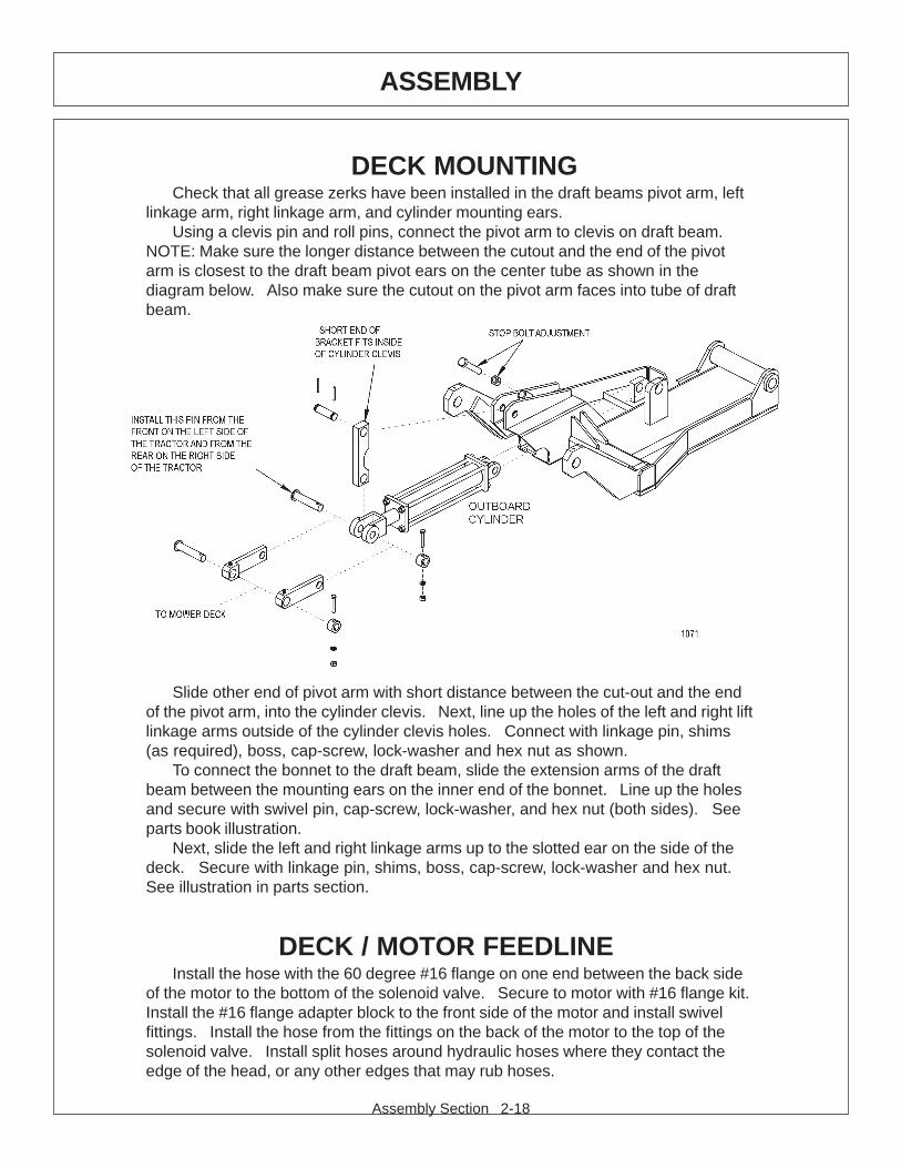
DECK MOUNTINGCheck that all grease zerks have been installed in the draft beams pivot arm, left
linkage arm, right linkage arm, and cylinder mounting ears.Using a clevis pin and roll pins, connect the pivot arm to clevis on draft beam.
NOTE: Make sure the longer distance between the cutout and the end of the pivotarm is closest to the draft beam pivot ears on the center tube as shown in thediagram below. Also make sure the cutout on the pivot arm faces into tube of draftbeam.
Slide other end of pivot arm with short distance between the cut-out and the endof the pivot arm, into the cylinder clevis. Next, line up the holes of the left and right liftlinkage arms outside of the cylinder clevis holes. Connect with linkage pin, shims(as required), boss, cap-screw, lock-washer and hex nut as shown.
To connect the bonnet to the draft beam, slide the extension arms of the draftbeam between the mounting ears on the inner end of the bonnet. Line up the holesand secure with swivel pin, cap-screw, lock-washer, and hex nut (both sides). Seeparts book illustration.
Next, slide the left and right linkage arms up to the slotted ear on the side of thedeck. Secure with linkage pin, shims, boss, cap-screw, lock-washer and hex nut.See illustration in parts section.
Assembly Section 2-19
ASSEMBLY
DECK / MOTOR FEEDLINE MOUNTING (cont.)Be sure that all grease zerks are installed in the draft beam pin bosses. Grease
all areas of the draft beam according to the instructions in the maintenance section.Re-check all fittings for tightness and be sure teflon tape has been used at allconnections.Fill hydraulic tank with fluid as recommended in the maintenance section. BE SURETO OPEN THE BALL VALVES. Start the tractor and operate the inboard cylinderthrough the entire stroke and the outboard cylinder through the bottom ¾ strokerepeatedly to clear the lines of air. DO NOT run outboard cylinder out to fullstroke until stop bolt has been adjusted!Check for oil leaks at all fittings and connections using a piece of paper or cardboard.If a leak is found, you must shut down the tractor and set the cutter head on theground. Before attempting to fix the leak, you must actuate the lift valve handlesseveral times to relieve any pressure in the lines. DO NOT USE HANDS TOCHECK FOR FLUID LEAKS!
Raise the tree point hitch and check the tractor internal hydraulics, fill to properlevel if needed.
STOP BOLT ADJUSTMENTExtend the outboard cylinder all the way out. Adjust the stop adjustment bolt
(located on the top of the draft beam) out until it is up against the bonnet. Lock thebolt down with the ¾” hex nut.
NOTE: When the outboard cylinder is fully extended, the bonnet or deck shouldeither be up against the stop or if travel locks are installed, it should be up against thetravel lock. It may be necessary to use either external or internal slugs on thecylinder to get the correct stroke. If the cutter head is against the stop and thecylinder has stoke remaining, serious damage will occur.
Proceed to final preparation for operation instructions on the next page.

Assembly Section 2-20
ASSEMBLY
FINAL PREPARATION FOR OPERATIONPlace operators safety and operation decals on the steering column and side
counsel where they are clearly visible to the operator. These decals should beunderstood by each operator of the machine in conjunction with the safety andoperation section of this book. The decals are to remain in good condition as areminder to the operator, and should be replaced if damaged.
Double check that all pivot points have been greased. Secure all hoses together withzip ties and wrap with split hose sections where friction may occur on the hose.
BEFORE starting or operating the tractor you must read andunderstand the safety and operation sections of this manualcompletely.
Before operating the mower, the cutter head and draft beam should be slowlymoved throughout the full range of motion. Watch for any condition that would causepinching or excess stress on the hoses. The steering and front axle travel shouldalso be carefully moved through their full range of motion. If any condition occurs inwhich the hoses contact the tires, the steering and / or front axle travel may need tobe limited as described in the tractor operators manual. This should also be done ifthe tires rub, or are extremely close to any other part of the mower such as thehydraulic tank or draft beam. This may include adding shims, or adjusting stop boltsin the tractor front to solve the problem. While checking motion, you should alsocheck that the control circuits are connected according to the operators decal for thevalve handles.
MOWER TESTINGTake the tractor to a place free of loose objects on the ground. Operate the
cylinders through their full range of motion again, to clear the lines of air. Follow theinstructions in the operation section to operate the mower. Vibration of the mowershould be minimal at all times. After a 5 minute test run, the knife bolts should beretorqued and once again after the first few hours of operation.
If any parts of this assembly section, or any other section of thismanual are not clearly understood you must contact your dealer or theaddress on the front of this manual for assistance!

OPERATIONSECTION
Operation Section 3-1
Operation Section 3-2
OPERATION
Safety is of primary importance to the owner / operator and to the manufacturer.The first section of this manual includes a list of Safety Messages, that, if followed,will help protect the operator and bystanders from injury or death. Many of themessages will be repeated throughout the manual. The owner / operator / dealershould know these Safety Messages before assembly and be aware of the hazardsof operating this mower during assembly, use, and maintenance.
The Safety Alert Symbol combined with a signal word, as seen below, isintended to warn the owner / operator of impending hazards and the degree of injurypossible during operation.
Indicates an imminently hazardous situation that, if not avoided, WILL result in DEATHOR VERY SERIOUS INJURY.
Indicates an imminently hazardous situation that, if not avoided, COULD result inDEATH OR SERIOUS INJURY.
Indicates an imminently hazardous situation that, if not avoided, MAY result in MINORINJURY.
Identifies special instructions or procedures that, if not strictly observed, could resultin damage to, or destruction of the machine, attachments or the enviroment.
NOTE: Identifies points of particular interest for more efficient or convienient operation orrepair. (SG-1)
Before any operation of tractor and mower, the user should read andunderstand the safety and operating instructions for both the tractor andthe mower. The user should also be familiar with the location andfunctions of the units instruments and controls. Being familiar with themachine and it’s controls will increase efficiency and reduce possibility of
serious injury or damage to the unit. The operator should work slowly and carefullyuntil he feels comfortable with the machine. Speed and skill will be attained mucheasier if the necessary time is spent to familiarize yourself with the machine and itsoperations.
Since tractor makes and models vary, we recommend reading and following theoperators manual provided by the manufacturer pertaining to your particular unit.
IMPORTANT!
Operation Section 3-3
OPERATION
STARTING TRACTOR AND MOWER
Check the operators manual received from the tractor manufacturer, fortheir recommendation and procedures pertaining to your particular make and model.
When rotating parts are in motion, serious injury may occur if caution isnot used or danger is not recognized. Never allow bystanders within 300feet of the machine when mower is in operation.
Be sure the ball valves on the mower hydraulic tank are OPEN beforestarting the tractor. Serious damage to the hydraulic system can occur ifthe valves are not open.
Check to make sure mower switch is in the “OFF” position. The unit isdesigned not to start if the switch is in the “on” position. If tractor startswith switch on, turn off tractor and contact your local Tiger dealership forassistance.
Start the tractor and allow the instruments to stabilize. Without starting themower, practice positioning the boom and deck. Remember, speed and skill will beattained easier if the necessary time is spent familiarizing yourself with the machineand its operations. When you feel comfortable at controlling the position of themower, return the mower to the travel position, and transport the mower to thedesired mowing location.
If mowing for the first time with a Tiger Boom Mower, we recommend choosing aditch or area relatively flat with a minimum of sign posts, guard rails, etc. As always,you should inspect the area for other objects that can cause potential hazards.
The Mower Control switch turns the mower “ON” and “OFF”. This switch is to bein the “OFF” position to start the tractor. The tractor will not start with the switch inthe “ON” position.
If tractor starts with switch on, turn off tractor and contactyour local Tiger dealership for assistance.
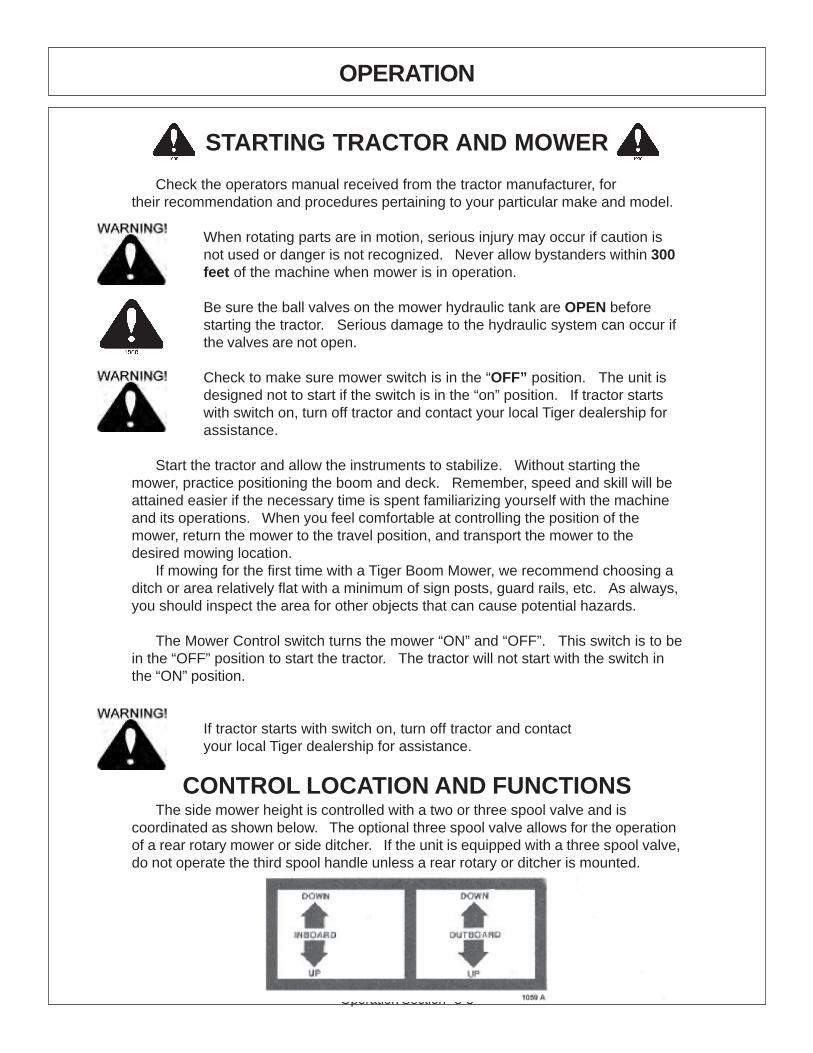
CONTROL LOCATION AND FUNCTIONSThe side mower height is controlled with a two or three spool valve and is
coordinated as shown below. The optional three spool valve allows for the operationof a rear rotary mower or side ditcher. If the unit is equipped with a three spool valve,do not operate the third spool handle unless a rear rotary or ditcher is mounted.

Operation Section 3-4
OPERATION
The rear mower height is controlled with the 3-point hitch control lever. Follow theinstructions for this control is the tractor operators manual. The tilt of the rear mower iscontrolled with the third spool if the lift valve and is coordinated as shown above.
The side and rear mower positions may optionally be controlled with the tractorsremote hydraulic connections or a combination of lift valve and remote hydraulics. If so,determine which position of the side or rear mower is to be controlled be each remotelever.
The side mower ON / OFF switch is located in a switch box mounted to the valvestand or cable controls for non-cab and cab units respectively. If operating a rear mower,the ON / OFF switch is located in the switch box with a side mower switch.
This machine may be equipped with an auxiliary oil temperature gauge, an amp gaugeor oil pressure gauge. If oil temperature reaches 200 degrees Fahrenheit, stop mowersand see trouble shooting section for possible causes. Keep an eye on all gauges forindication of problems.
MOWER OPERATIONWhen rotating parts are in motion, serious injury may occur if caution isnot used or danger is not recognized. Never allow bystanders within 300feet of the machine when in operation. Extreme care should be takenwhen operating near loose objects – such as gravel, rocks and debris.These conditions should be avoided.
The rotating parts in this machine have been designed and tested for rugged use.However, they could fail upon impact with heavy solid objects – such as steel guard rails,concrete abutments, etc., causing them to be thrown at a very high velocity. Never allowcutter head to contact such objects. Inspecting the cutting area for such objects prior tomowing can help eliminate these potential hazards.
Once on location, lower the mower deck slightly above the material to be cut, sothe mower does not have to start under a load. Bring the R.P.M. of the tractor up to 1200and engage the side mower. If a rear mower is being used, allow the R.P.M. to return to1200 before engaging the rear mower.
The flail mower deck should be carried so that part of the weight is carried by theground roller. When the flail is carried this way, the roller also follows the contour of theground more easily during mowing operations.
When cutting small shrubs or brush, begin each pass at the top of the material andwork down with each consecutive pass. Use a low speed to allow the cutting blades timeto mulch as well as cut the foliage. When the initial pass has been made, disengage themower and return the mower to the travel position. Return to the starting point and makenext pass, etc. The flail head is not intended for cutting heavy brush, or for continuallycutting brush. Wear or damage of the blades will occur rapidly when the flail cutter isused this way.
Operation Section 3-5
OPERATION
To ensure a clean cut, engine speed should be maintained at approximately 1800– 2200 R.P.M. If the tractor slows to less than 1800 R.P.M., shift to the next lowergear. DO NOT ride the clutch, this will cause premature clutch failure. The engineshould not be operated at any time at more than 2400 R.P.M. on the tractortachometer.
The mower will operate more efficiently in tougher conditions and with less powerif the knives are kept sharp. If the mower begins to vibrate, stop the tractor, check forwire wrapped in the spindle or damaged knives. When replacing knives, replace allknives with new knives to ensure proper balance so the mower will not vibrate.Severe vibration will result, if knives with unequal wear are used. Follow theinstructions in the maintenance section closely when replacing knife blades.
If bystanders approach within 300 feet while mower is in operation turnmower switch “OFF” immediately! After shutdown, never leave thetractor or allow bystanders to approach within 300 FEET of the unit until allmotion stops completely.
When encountering a very severe condition which causes the tractor to stall,disengage mower, start tractor, raise the mower from the cut. Shut tractor off andinspect the mower, blades and disk for damage before engaging mower again.
If the blades jam or stop, disengage the clutch and raise the head slightly or backthe tractor up. Normally, this will clear the cutter head. If not, shut off the mower(s),raise the cutter heads, turn off the tractor and set the parking brake. After all motionstops completely, leave the tractor and clear the cutting heads manually.
After the first day of operation, all bolts should be checked and tightenedsecurely.This should be done periodically to ensure the bolts do not become loose and causedamage to the tractor or mower, or injury to the operator.
Operation Section 3-6
OPERATION
TRANSPORTING MOWER
Transporting under the units own power:When transporting between job sites or between cutting passes, the following
procedure should be followed: Shut off the power to the cutting head(s) and allow allmotion to come to a complete stop. Raise the draft beam to it’s highest position.Raise the side mower until the deck stops against the draft beam. Raise the rearmower with the 3-point hitch control lever. The unit is now in position for selftransportation.
Transporting unit by flatbed trailer:Most tractors with a side mounted mower head attached will be over legal
transporting width (102” wide). For this reason, one of the following proceduresmust be followed.
1: Transporting with side mower attached: Use a loading dock or ramp to loadtractor onto the trailer. Center the tractor with the mowers attached between thesides of the trailer. Make sure the draft beam and head are fully raised and secured.Lower the rear mower onto the trailer. Secure the tractor and rear mower to thetrailer with chains. Obtain proper over-width permits and mark the vehicle andmower as over-width as required be law. Check the tractor operators manual for anytractor requirements to transport by flatbed trailer.
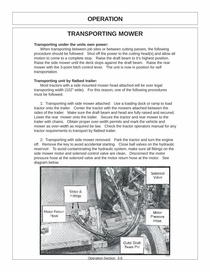
2: Transporting with side mower removed: Park the tractor and turn the engineoff. Remove the key to avoid accidental starting. Close ball valves on the hydraulicreservoir. To avoid contaminating the hydraulic system, make sure all fittings on theside mower motor and solenoid control valve are clean. Disconnect the motorpressure hose at the solenoid valve and the motor return hose at the motor. Seediagram below.
Operation Section 3-7
OPERATION
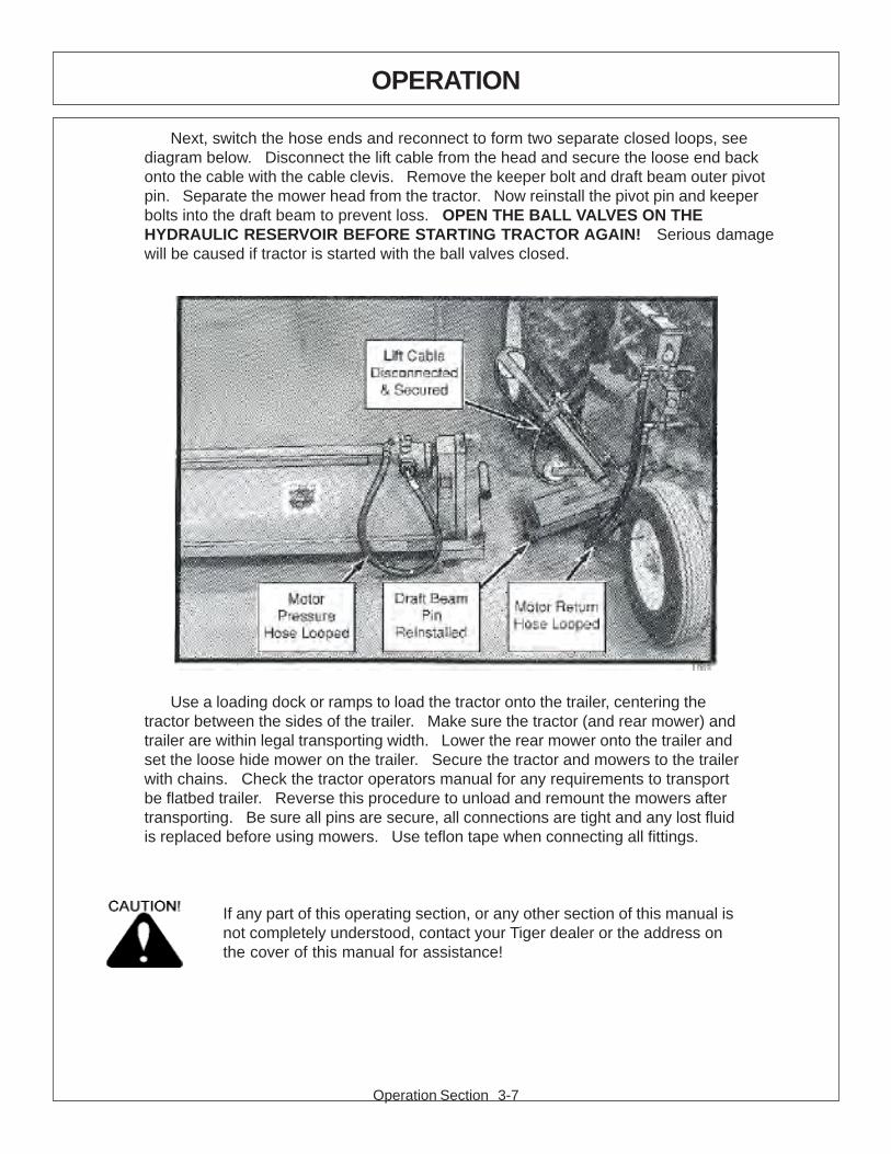
Next, switch the hose ends and reconnect to form two separate closed loops, seediagram below. Disconnect the lift cable from the head and secure the loose end backonto the cable with the cable clevis. Remove the keeper bolt and draft beam outer pivotpin. Separate the mower head from the tractor. Now reinstall the pivot pin and keeperbolts into the draft beam to prevent loss. OPEN THE BALL VALVES ON THEHYDRAULIC RESERVOIR BEFORE STARTING TRACTOR AGAIN! Serious damagewill be caused if tractor is started with the ball valves closed.
Use a loading dock or ramps to load the tractor onto the trailer, centering thetractor between the sides of the trailer. Make sure the tractor (and rear mower) andtrailer are within legal transporting width. Lower the rear mower onto the trailer andset the loose hide mower on the trailer. Secure the tractor and mowers to the trailerwith chains. Check the tractor operators manual for any requirements to transportbe flatbed trailer. Reverse this procedure to unload and remount the mowers aftertransporting. Be sure all pins are secure, all connections are tight and any lost fluidis replaced before using mowers. Use teflon tape when connecting all fittings.
If any part of this operating section, or any other section of this manual isnot completely understood, contact your Tiger dealer or the address onthe cover of this manual for assistance!

Operation Section 3-8
OPERATION
INSPECTION SHEETS
Operation Section 3-9
OPERATION
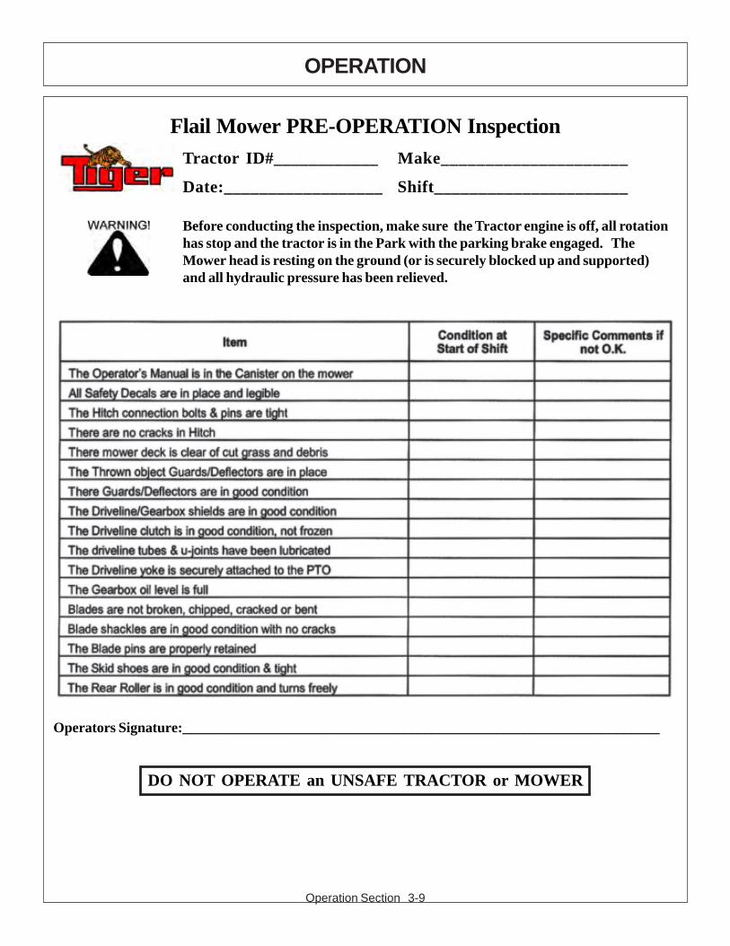
Flail Mower PRE-OPERATION InspectionTractor ID#____________ Make_____________________
Date:__________________ Shift______________________
Before conducting the inspection, make sure the Tractor engine is off, all rotationhas stop and the tractor is in the Park with the parking brake engaged. TheMower head is resting on the ground (or is securely blocked up and supported)and all hydraulic pressure has been relieved.
Operators Signature:___________________________________________________________________
DO NOT OPERATE an UNSAFE TRACTOR or MOWER
Operation Section 3-10
OPERATION
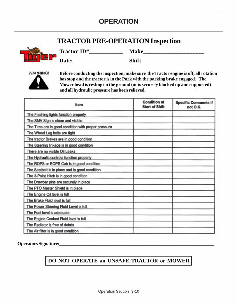
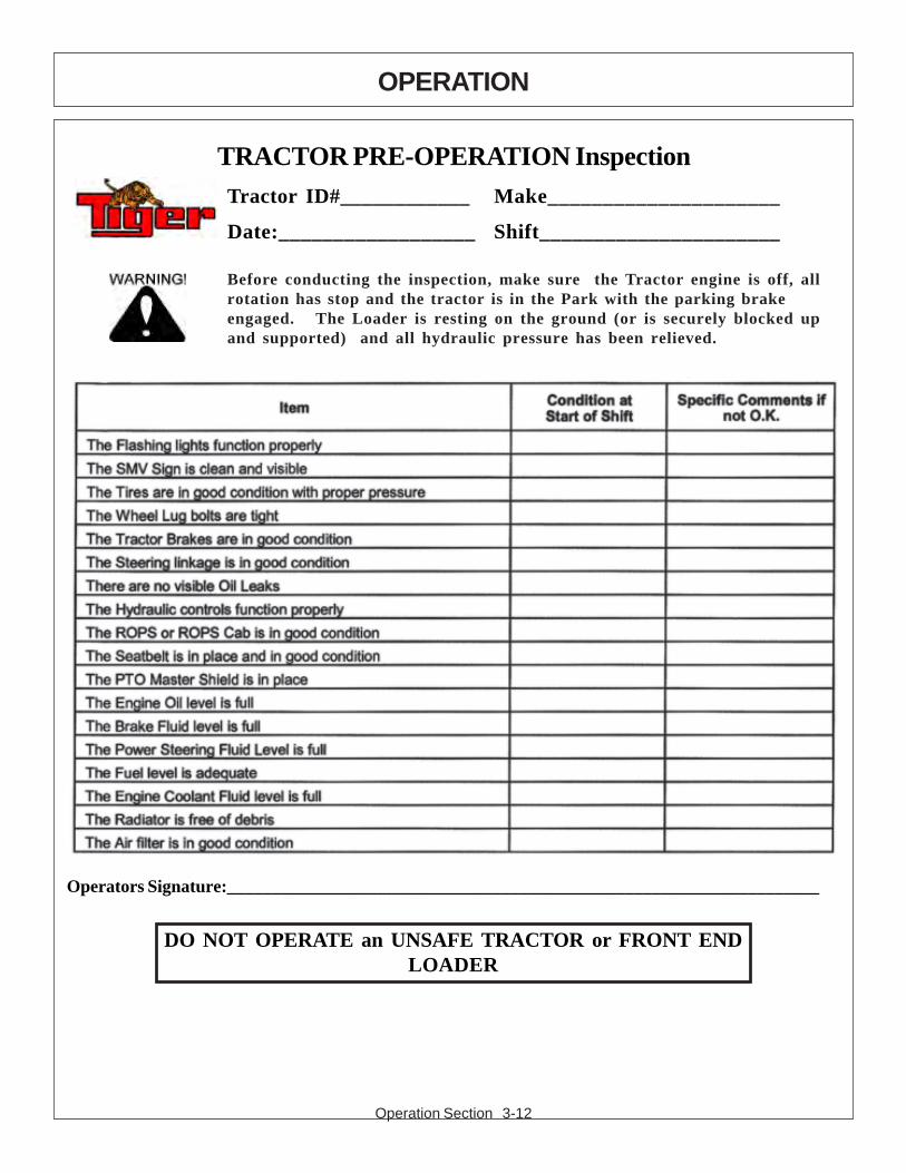
TRACTOR PRE-OPERATION InspectionTractor ID#____________ Make_____________________
Date:__________________ Shift______________________
Before conducting the inspection, make sure the Tractor engine is off, all rotationhas stop and the tractor is in the Park with the parking brake engaged. TheMower head is resting on the ground (or is securely blocked up and supported)and all hydraulic pressure has been relieved.
Operators Signature:___________________________________________________________________
DO NOT OPERATE an UNSAFE TRACTOR or MOWER
Operation Section 3-11
OPERATION
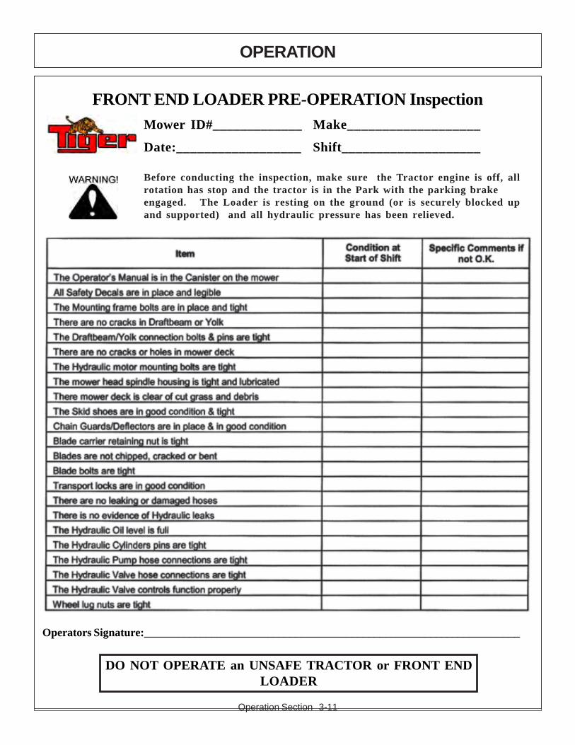
FRONT END LOADER PRE-OPERATION InspectionMower ID#_____________ Make___________________
Date:__________________ Shift____________________
Before conducting the inspection, make sure the Tractor engine is off, allrotation has stop and the tractor is in the Park with the parking brakeengaged. The Loader is resting on the ground (or is securely blocked upand supported) and all hydraulic pressure has been relieved.
Operators Signature:___________________________________________________________________
DO NOT OPERATE an UNSAFE TRACTOR or FRONT ENDLOADER
Operation Section 3-12
OPERATION
TRACTOR PRE-OPERATION InspectionTractor ID#____________ Make_____________________
Date:__________________ Shift______________________
Before conducting the inspection, make sure the Tractor engine is off, allrotation has stop and the tractor is in the Park with the parking brakeengaged. The Loader is resting on the ground (or is securely blocked upand supported) and all hydraulic pressure has been relieved.
Operators Signature:___________________________________________________________________
DO NOT OPERATE an UNSAFE TRACTOR or FRONT ENDLOADER

MAINTENANCESECTION
Maintenance Section 4-1
Maintenance Section 4-2
MAINTENANCE
Tiger Mowers are designed for high performance and rugged durability, yet withsimplified maintenance. The purpose of this section of the manual is to help theoperator in the regular servicing of the mower. Regular maintenance at theintervals mentioned will result in the maximum efficiency and long life of the TigerMower.
When you purchase a Tiger Mower you also acquire another valuable asset,Tiger’s parts organization. Our rapid and efficient service has guaranteed thecustomer satisfaction for many years. Tiger parts keep up with the demands forefficiency, safety and endurance expected of the Tiger Mower.
BREAK IN PERIOD
MAINTENANCE PRECAUTIONS
In addition to following the break in instructions for your particular tractor, the in-tankhydraulic fluid filter should be replaced after the first 50 hours of service. Thereafterthe filter should be replaced every 500 hours, or yearly, which ever comes first.
Re-torque wheel lugs after first five hours of operation and periodicallythereafter. See torque specifications listed in the tractor’s service manual for yourparticular model. Wheel lugs must always be re-torqued whenever a wheel isremoved and reinstalled.
· Be sure end of grease gun and zerks are clean before using. Debris injectedintobearings, etc. with grease will cause immediate damage.· DO NOT use a power grease gun to lubricate bearings. These require verysmall and exact amounts of lubrication. Refer to the detailed maintenance sectionfor specificlubrication instructions. Do Not over-grease bearings.· Lexan windows should be washed with mild soap or detergent and luke warmwater, using a soft clean sponge or soft cloth. DO NOT use abrasive or alkalinecleaners or metal scrapers on lexan windows!· Be alert to maintenance indicators such as the in-tank filter pressure gauge,hydraulic reservoir sight gauge, etc. Take the required action to correct anyproblems immediately.· Release of energy from pressurized systems may cause inadvertent actuationof cylinders, or sudden release of compressed springs. Before disconnecting anyhoses relieve pressure by shutting tractor off, setting cutter on ground and actuatinglift valve handles.
DO NOT use hands to check for suspected leaks in hydraulic hoses!Hydraulic fluid escaping under pressure can have sufficient force topenetrate skin and cause serious injury. If fluid is injected into skin, itmust be surgically removed within a few hours or gangrene may result.Use a small piece of wood or cardboard, not hands, to search for pinhose leaks. Be sure all pressure is relieved whenever disconnectinglines. Be sure all connections are tight and hoses and lines are notdamaged before applying pressure.

Maintenance Section 4-3
MAINTENANCE
REGULAR MAINTENANCE
The intervals at which regular servicing should be done are based on hours ofoperation. Use the tractors hour meter to determine when regular servicing isrequired.
This symbol indicates a point that needs to be greased at an intervalnoted in the section below. Refer to the Detailed Maintenance sectionfor further instructions on greasing. Copy and use the DailyMaintenance sheet located at the end of this section.
DAILY OR EVERY 8 HOURS
ITEM SERVICE COMMENTS
Drive Shaft Yoke, U-Joint Grease Grease as instructed in & Stub Shaft detailed maint. section
Pump Drive Shaft Check and Lube Insure drive shaft endplay
Crankshaft Adapter Check rubber grommets Replace grommets ifdamaged or missing
Pivot Points Lubricate Inject grease until itappears at ends
Hydraulic Fittings Check for leaks Tighten when needed.Do Not use hands tocheck for leaks, seemaint. Precautions
Knives Check Inspect for missing ordamaged knives, changeor sharpen as needed
Cutter shaft mounting bolts Check 1/2” x 2” torque to 84 ft. lbs.(cutter shaft to deck)Knife mounting bolts Check Retorque to knife(knife to cutter shaft) replacement specificationsBelts Check / Adjust Check if broken, tighten
as requiredMain Frame and Check Retorque bolts to torqueDeck specifications in this sectionHydraulic Fluid Level Check Add if required per
fluid recommendationsRear Flail Drive (if applicable) Lubricate Grease as instructed inBearing Flange and detailed maint. sectionShaft CouplerCutter Shaft and Lubricate Grease as instructedGround Roller in detailed maint. section

Maintenance Section 4-4
MAINTENANCE
WEEKLY OR EVERY 50 HOURSITEM SERVICE COMMENTS
In Tank Hyd. Fluid Change Change after first 50Filter hours only, then every(10 micron filter) 500 hours or yearly
In-Line High Pressure Change Change after first 50Filter hours only, then every(10 micron filter) 500 hours or yearly
MONTHLY OR EVERY 150 HOURSHydraulic Fluid Level Check Add as needed
Hyd. Tank Breather Clean / Check / Replace Clean or replaceElement as required
Rear Tire Type Max P.S.I. 480/80R38 29 18.4-34 26 18.4-38 26
YEARLY OR EVERY 500 HOURSHyd. Tank Fluid Change
In Tank Hyd. Fluid ChangeFilter(10 micron filter)
In-Line High Pressure Change or Change when indicatedFilter by restriction indicator.(10 micron filter)
Hyd. Tank Breather Change
TROUBLE SHOOTINGSYMPTOMS CAUSE REMEDY
Vibration 1. Loose bolts 1. Check all bolts and tighten totorque specs. in this section.
2. Cutter assembly 2a. Check for damaged blades, disc.Unbalanced or cutter shaft. Replace if needed.
2b. Check for wire, rope, etc. entangledin cutter assembly
Mower will not lift 1. Hyd. Fluid low 1. Check and refill Hyd. Fluid2. Leaks in line 2. Tighten or replace fittings and hoses3. Faulty relief valve 3. Check pressure in line. Line
in Control Valve pressure should be at least 2500 PSI4. Kinked or blocked 4. Clean or replace lines5. Faulty cylinder 5. Inspect, repair or replace cylinder

Maintenance Section 4-5
MAINTENANCE
SYMPTOMS CAUSE REMEDY
Mower will not start 1. Blown fuse 1. Check fuse between mower switchor run and ignition / replace
2. Ball valves closed 2. Make sure valves are open3. Low oil level 3. Check Hyd. tank and fill4. Line leak 4. Check all fittings and lines,
re-tighten or replace.Oil Temperature rises 1. Low oil level 1. Bring oil to proper levelabove 200 deg. F 2. Kinked or blocked 2. Inspect, Repair, or Replace hoses
3. Worn pump/motor3. Disable and repairMower will not start 1. Electronic 1a. Without the tractor running, turnor run, cont. solenoid faulty the mower switch to on. A low
audible click should be heard if thesolenoid is engaging the solenoidspool. If click is not heard, leaveswitch in on position and with ascrewdriver or other steel object,touch the small nut on the end of thesolenoid. If the metallic object is notattracted to the nut, check the fuseand wiring for an open circuit. If theobject is attracted but no “click” isheard, replace the solenoid.
1b. Remove the four bolts holding thesmall block to the main block. Liftand remove small block beingcareful not to damage O-rings / filter.Clean filter and re-install.
1c. Remove large nut on side of largevalve block. Remove spring, and useneedle nose vise grip to pull spoolfrom block. Check block and spoolfor contaminates and scratches.Clean parts or replace if scratched.
Motor runs but 1. Belts 1. Inspect belts and pulleys. Replacewill not cut. belts and repair as needed.
2. Tensioner 2. Adjust tensioner nut until flat washerwasher is flush with top of guide.
Motor turns slowly 1. Contaminants 1. Remove large nut on side of largeor not at all. restricting spool valve block. Remove spring, and use
movement in needle nose vise grip to pull spoolvalve body. from block. Check block and spool
for contaminates and scratches.Clean parts or replace if scratched.
2. Suction lines 2. Check for crimp or obstruction inobstructed suction hose
3. Low oil level 3. Check Hyd. tank level and fillPump will not work 1. Excessive wear 1. Disassemble and repair.
on internal parts

Maintenance Section 4-6
MAINTENANCE
Motor will not work 1. Excessive wear 1. Disassemble and repair.on internal parts
NOTE: If flow meter is available, check pressure and flow volume for allsuspected hydraulic problems.
If the solution to your problem cannot be found in this section, call theTechnical Service representative at the number shown on the front cover ofthis manual.

Maintenance Section 4-7
MAINTENANCE
TORQUE SPECIFICATIONS
* These are intended to be general specifications. See tractor operators or service manual for exact specifications for your unit.

Maintenance Section 4-8
MAINTENANCE
LUBRICATION RECOMMENDATIONS
Description Application General Specification RecomendedMobil Lubricant
Tractor Hydraulics Reservoir JD-20C Mobilfluid 424MF M1135,M1141FNHM2C134D (FNH201)
Mower Hydraulics ReservoirCold Temperatures 0 F Start-Up ISO 46 Anti-Wear - Low Temp Mobil DTE 15MNormal Temperatures 10 F Start-Up JD-20C Mobilfluid 424
MF M1135,M1141FNH M2C134D (FNH201)
Normal Temperatures 15 F Start-Up ISO 46 Anti-Wear Mobil DTE 25High Operating Temp. Above 90 F ISO 100 Anti-Wear Mobil DTE 18M
Flail Rear Gearbox Grease PAO Synthetic Extreme Mobil SHC 75W-90Pressure Gear Lube Mobil 1 Synthetic Gear
Cutter Shaft & Ground Grease Lithium-Complex Mobilgrease CM-S
Roller Shaft (Flail) Gun Extreme Pressure
NLGI 2 - ISO 320
Drive Shaft Coupler Grease Lithium-Complex Mobilgrease CM-S(Flail and Rotary) Gun Extreme Pressure
NLGI2 - ISO 320
Drive Shaft Yoke, U-Joint & Stub Shaft Grease Lithium-Complex Mobilgrease CM-SGun Extreme Pressure
NLGI2 - ISO 320
Boom Swivel Grease Lithium-Complex Mobilgrease CM-SBoom Cylinder Pivots Gun Extreme pressure(Rotary & Flail Boom) NLGI2 - ISO 320
Deck Boom Pivot & Grease Lithium-Complex Mobilgrease CM-S
Deck Stop Adjustment Gun Extreme pressure(Rotary & Flail) NLGI 2 - ISO 320
Deck Spindle (Rotary) Grease Tiger Spindle Lubricant Mobilith SHC 220Gun part number 06540000
9-13-02
Maintenance Section 4-9
MAINTENANCE
POLYCARBONATE CARE & MAINTENANCE
The proprietary UV and Abrasion Resistant surface coating on SHIELDS®
SUPERCOATED™ polycarbonate significantly improves performance. Periodiccleaning using proper procedures and compatible cleaners are recommended toprolong service life. Tiger Corp. polycarbonate is SUPERCOATED™ on both sides.
CLEANING THE SUPERCOAT™ HARD-COAT1. Wash with a mild solution of soap or detergent and lukewarm water.2. Using a soft cloth or sponge, gently wash the sheet to loosen dirt and grime and rinse well
with clean water.3. To prevent water spotting, thoroughly dry with chamois or cellulose sponge.4. Avoid the use of abrasive cleaners, squeegees and/or other cleaning implements that may
mar or gouge the coating.
CLEANING AGENTS WHICH HAVE BEEN FOUND TO BE COMPATIBLE UNDER LABORATORYCONDITIONS:
• Aqueous Solutions of Soaps and DetergentsWindex1 Top Job2 Joy2 Mr. Clean2
Fantastik3 Formula 4094 Sumalight D12 Brucodecid
• Organic SolventsButyl Cellosolve Kerosene Hexel, F.O. 554 Naphtha (VM&P grade)Neleco-Placer Turco 5042
• AlcoholsMethanol Isopropyl
All residual organic solvents should be removed with a secondary rinse.
GRAFFITI REMOVALButyl cellosolve (for removal of paints, marking pen inks, lipstick, etc.). The use of
masking tape, adhesive tape or lint removal tools works well for lifting off old weatheredpaints.
To remove labels, stickers, etc., the use of kerosene or VM&P naphtha are generallyeffective. When the solvent will not penetrate sticker material, apply heat (hair dryer) tosoften the adhesive and promote removal.
IMPORTANT: If a material is found to be incompatible in a short-term test, it will usually befound to be incompatible in the field. The converse, however, is not always true. Favorableperformance is no guarantee that actual end-use conditions have been duplicated.Therefore, these results should be used as a guide only and it is recommended that theuser test the products under actual end-use conditions.
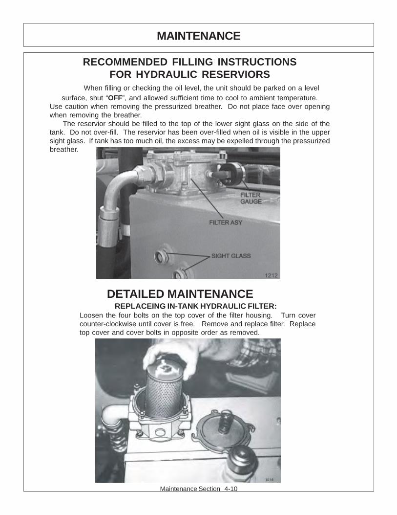
Maintenance Section 4-10
MAINTENANCE
RECOMMENDED FILLING INSTRUCTIONSFOR HYDRAULIC RESERVIORS
When filling or checking the oil level, the unit should be parked on a levelsurface, shut “OFF”, and allowed sufficient time to cool to ambient temperature.
Use caution when removing the pressurized breather. Do not place face over openingwhen removing the breather.
The reservior should be filled to the top of the lower sight glass on the side of thetank. Do not over-fill. The reservior has been over-filled when oil is visible in the uppersight glass. If tank has too much oil, the excess may be expelled through the pressurizedbreather.
DETAILED MAINTENANCEREPLACEING IN-TANK HYDRAULIC FILTER:
Loosen the four bolts on the top cover of the filter housing. Turn covercounter-clockwise until cover is free. Remove and replace filter. Replacetop cover and cover bolts in opposite order as removed.
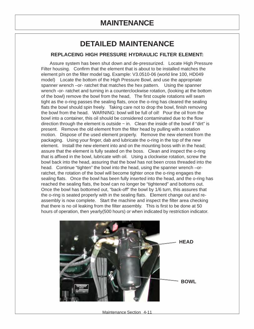
Maintenance Section 4-11
MAINTENANCE
DETAILED MAINTENANCEREPLACEING HIGH PRESSURE HYDRAULIC FILTER ELEMENT:
Assure system has been shut down and de-pressurized. Locate High PressureFilter housing. Confirm that the element that is about to be installed matches theelement p/n on the filter model tag. Example: V3.0510-06 (world line 100, HD049model) Locate the bottom of the High Pressure Bowl, and use the appropriatespanner wrench –or- ratchet that matches the hex pattern. Using the spannerwrench -or- ratchet and turning in a counterclockwise rotation, (looking at the bottomof the bowl) remove the bowl from the head, The first couple rotations will seamtight as the o-ring passes the sealing flats, once the o-ring has cleared the sealingflats the bowl should spin freely. Taking care not to drop the bowl, finish removingthe bowl from the head. WARNING: bowl will be full of oil! Pour the oil from thebowl into a container, this oil should be considered contaminated due to the flowdirection through the element is outside ~ in. Clean the inside of the bowl if “dirt” ispresent. Remove the old element from the filter head by pulling with a rotationmotion. Dispose of the used element properly. Remove the new element from thepackaging. Using your finger, dab and lubricate the o-ring in the top of the newelement. Install the new element into and on the mounting boss with in the head;assure that the element is fully seated on the boss. Clean and inspect the o-ringthat is affixed in the bowl, lubricate with oil. Using a clockwise rotation, screw thebowl back into the head, assuring that the bowl has not been cross threaded into thehead. Continue “tighten” the bowl into the head, using the spanner wrench –or-ratchet, the rotation of the bowl will become tighter once the o-ring engages thesealing flats. Once the bowl has been fully inserted into the head, and the o-ring hasreached the sealing flats, the bowl can no longer be “tightened” and bottoms out.Once the bowl has bottomed out, “back-off” the bowl by 1/6 turn, this assures thatthe o-ring is seated properly with in the sealing flats. Element change out and re-assembly is now complete. Start the machine and inspect the filter area checkingthat there is no oil leaking from the filter assembly. This is first to be done at 50hours of operation, then yearly(500 hours) or when indicated by restriction indicator.
BOWL
HEAD
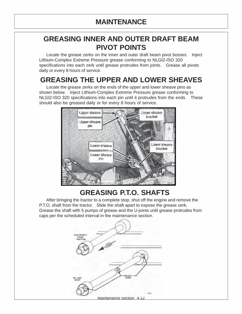
Maintenance Section 4-12
MAINTENANCE
GREASING INNER AND OUTER DRAFT BEAMPIVOT POINTS
Locate the grease zerks on the inner and outer draft beam pivot bosses. InjectLithium-Complex Extreme Pressure grease conforming to NLGI2-ISO 320specifications into each zerk until grease protrudes from joints. Grease all pivotsdaily or every 8 hours of service.
GREASING THE UPPER AND LOWER SHEAVESLocate the grease zerks on the ends of the upper and lower sheave pins as
shown below. Inject Lithium-Complex Extreme Pressure grease conforming toNLGI2-ISO 320 specifications into each pin until it protrudes from the ends. Theseshould also be greased daily or for every 8 hours of service.
GREASING P.T.O. SHAFTSAfter bringing the tractor to a complete stop, shut off the engine and remove the
P.T.O. shaft from the tractor. Slide the shaft apart to expose the grease zerk.Grease the shaft with 5 pumps of grease and the U-joints until grease protrudes fromcaps per the scheduled interval in the maintenance section.
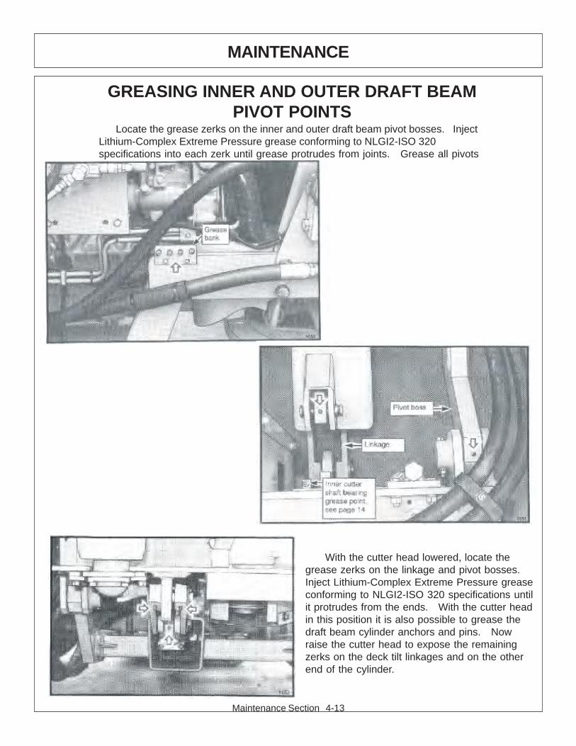
Maintenance Section 4-13
MAINTENANCE
GREASING INNER AND OUTER DRAFT BEAMPIVOT POINTS
Locate the grease zerks on the inner and outer draft beam pivot bosses. InjectLithium-Complex Extreme Pressure grease conforming to NLGI2-ISO 320specifications into each zerk until grease protrudes from joints. Grease all pivots
With the cutter head lowered, locate thegrease zerks on the linkage and pivot bosses.Inject Lithium-Complex Extreme Pressure greaseconforming to NLGI2-ISO 320 specifications untilit protrudes from the ends. With the cutter headin this position it is also possible to grease thedraft beam cylinder anchors and pins. Nowraise the cutter head to expose the remainingzerks on the deck tilt linkages and on the otherend of the cylinder.
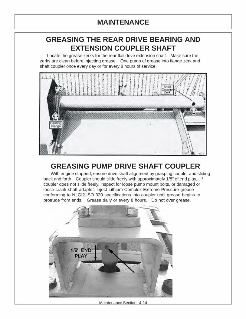
Maintenance Section 4-14
MAINTENANCE
GREASING PUMP DRIVE SHAFT COUPLERWith engine stopped, ensure drive shaft alignment by grasping coupler and sliding
back and forth. Coupler should slide freely with approximately 1/8” of end play. Ifcoupler does not slide freely, inspect for loose pump mount bolts, or damaged orloose crank shaft adapter. Inject Lithium-Complex Extreme Pressure greaseconforming to NLGI2-ISO 320 specifications into coupler until grease begins toprotrude from ends. Grease daily or every 8 hours. Do not over grease.
GREASING THE REAR DRIVE BEARING ANDEXTENSION COUPLER SHAFT
Locate the grease zerks for the rear flail drive extension shaft. Make sure thezerks are clean before injecting grease. One pump of grease into flange zerk andshaft coupler once every day or for every 8 hours of service.
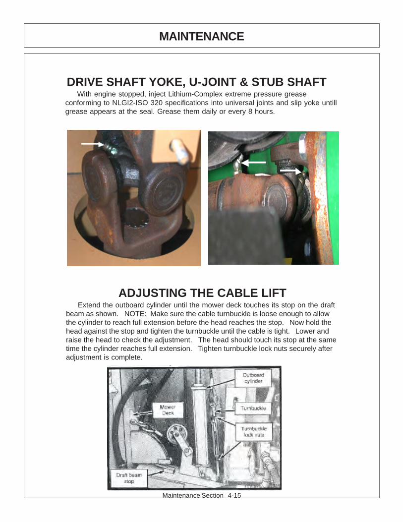
Maintenance Section 4-15
MAINTENANCE
ADJUSTING THE CABLE LIFTExtend the outboard cylinder until the mower deck touches its stop on the draft
beam as shown. NOTE: Make sure the cable turnbuckle is loose enough to allowthe cylinder to reach full extension before the head reaches the stop. Now hold thehead against the stop and tighten the turnbuckle until the cable is tight. Lower andraise the head to check the adjustment. The head should touch its stop at the sametime the cylinder reaches full extension. Tighten turnbuckle lock nuts securely afteradjustment is complete.
DRIVE SHAFT YOKE, U-JOINT & STUB SHAFTWith engine stopped, inject Lithium-Complex extreme pressure grease
conforming to NLGI2-ISO 320 specifications into universal joints and slip yoke untillgrease appears at the seal. Grease them daily or every 8 hours.
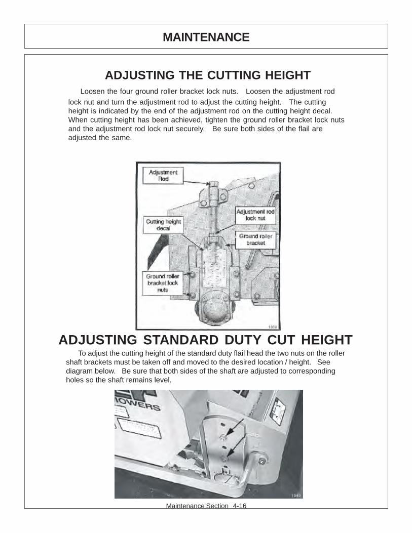
Maintenance Section 4-16
MAINTENANCE
ADJUSTING STANDARD DUTY CUT HEIGHTTo adjust the cutting height of the standard duty flail head the two nuts on the roller
shaft brackets must be taken off and moved to the desired location / height. Seediagram below. Be sure that both sides of the shaft are adjusted to correspondingholes so the shaft remains level.
ADJUSTING THE CUTTING HEIGHTLoosen the four ground roller bracket lock nuts. Loosen the adjustment rod
lock nut and turn the adjustment rod to adjust the cutting height. The cuttingheight is indicated by the end of the adjustment rod on the cutting height decal.When cutting height has been achieved, tighten the ground roller bracket lock nutsand the adjustment rod lock nut securely. Be sure both sides of the flail areadjusted the same.
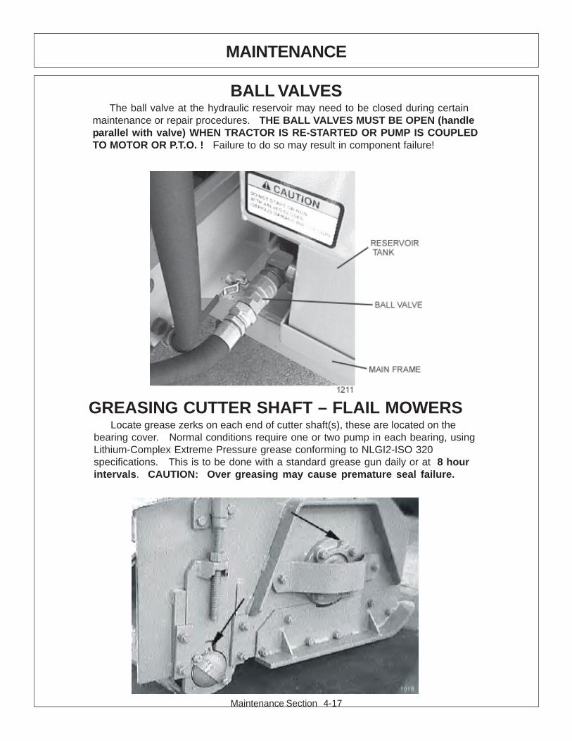
Maintenance Section 4-17
MAINTENANCE
GREASING CUTTER SHAFT – FLAIL MOWERSLocate grease zerks on each end of cutter shaft(s), these are located on the
bearing cover. Normal conditions require one or two pump in each bearing, usingLithium-Complex Extreme Pressure grease conforming to NLGI2-ISO 320specifications. This is to be done with a standard grease gun daily or at 8 hourintervals. CAUTION: Over greasing may cause premature seal failure.
BALL VALVESThe ball valve at the hydraulic reservoir may need to be closed during certain
maintenance or repair procedures. THE BALL VALVES MUST BE OPEN (handleparallel with valve) WHEN TRACTOR IS RE-STARTED OR PUMP IS COUPLEDTO MOTOR OR P.T.O. ! Failure to do so may result in component failure!
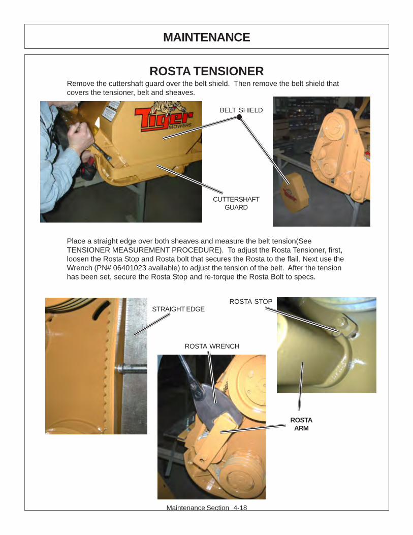
Maintenance Section 4-18
MAINTENANCE
ROSTA TENSIONERRemove the cuttershaft guard over the belt shield. Then remove the belt shield thatcovers the tensioner, belt and sheaves.
Place a straight edge over both sheaves and measure the belt tension(SeeTENSIONER MEASUREMENT PROCEDURE). To adjust the Rosta Tensioner, first,loosen the Rosta Stop and Rosta bolt that secures the Rosta to the flail. Next use theWrench (PN# 06401023 available) to adjust the tension of the belt. After the tensionhas been set, secure the Rosta Stop and re-torque the Rosta Bolt to specs.
CUTTERSHAFTGUARD
BELT SHIELD
STRAIGHT EDGE
ROSTA WRENCH
ROSTA STOP
ROSTAARM
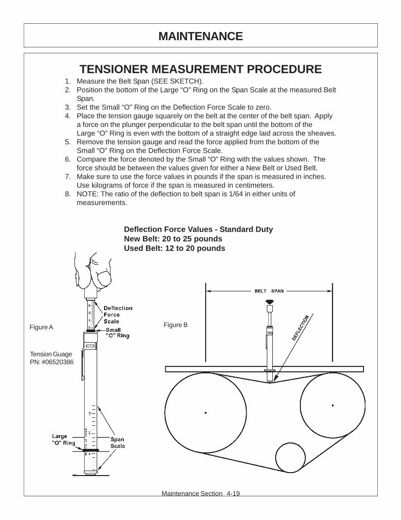
Maintenance Section 4-19
MAINTENANCE
TENSIONER MEASUREMENT PROCEDURE1. Measure the Belt Span (SEE SKETCH).2. Position the bottom of the Large “O” Ring on the Span Scale at the measured Belt
Span.3. Set the Small “O” Ring on the Deflection Force Scale to zero.4. Place the tension gauge squarely on the belt at the center of the belt span. Apply
a force on the plunger perpendicular to the belt span until the bottom of theLarge “O” Ring is even with the bottom of a straight edge laid across the sheaves.
5. Remove the tension gauge and read the force applied from the bottom of theSmall “O” Ring on the Deflection Force Scale.
6. Compare the force denoted by the Small “O” Ring with the values shown. Theforce should be between the values given for either a New Belt or Used Belt.
7. Make sure to use the force values in pounds if the span is measured in inches.Use kilograms of force if the span is measured in centimeters.
8. NOTE: The ratio of the deflection to belt span is 1/64 in either units ofmeasurements.
Deflection Force Values - Standard DutyNew Belt: 20 to 25 poundsUsed Belt: 12 to 20 pounds
Figure A Figure B
Tension GuagePN: #06520386

Maintenance Section 4-20
MAINTENANCE
GREASING THE IDLER TENSION ARMS
Locate the access holes and grease zerks in the belt shields of the side and rearflails. Normal conditions require one pump daily or every 8 hours of service withmulti purpose grease.
IDLER TENSIONING
Locate the idler tensioning rod for each flail. Loosen the locking nut. Turn theadjusting nut until the washer in between the spring and nuts is flush with the springhousing or guide. Tighten locking nut securely. For standard cut on side flail adjustuntil the spring washer is flush with the top of the spring housing, as shown below.Use this same method to adjust hydraulically driven rear flails.
GREASING GROUND ROLLER SHAFT – FLAILLocate grease zerks on each end of roller tube at lower rear of head. Normal
conditions require one or two pump in each bearing, using Lithium-ComplexExtreme Pressure grease conforming to NLGI2-ISO 320 specifications. This is tobe done with a standard grease gun daily or at 8 hour intervals. CAUTION:Over greasing may cause premature seal failure.
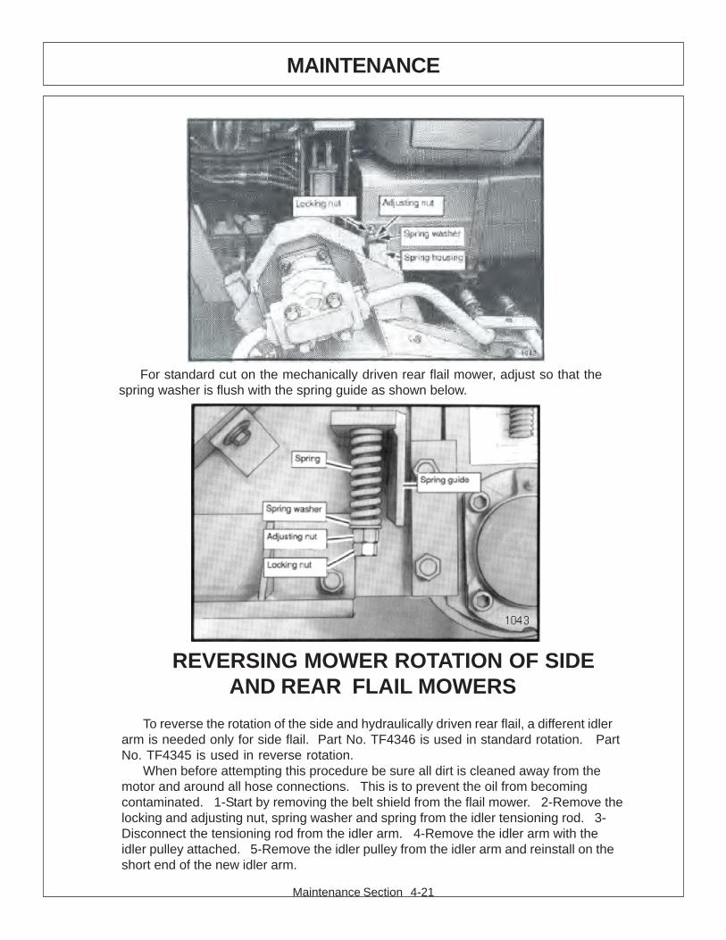
Maintenance Section 4-21
MAINTENANCE
REVERSING MOWER ROTATION OF SIDEAND REAR FLAIL MOWERS
To reverse the rotation of the side and hydraulically driven rear flail, a different idlerarm is needed only for side flail. Part No. TF4346 is used in standard rotation. PartNo. TF4345 is used in reverse rotation.
When before attempting this procedure be sure all dirt is cleaned away from themotor and around all hose connections. This is to prevent the oil from becomingcontaminated. 1-Start by removing the belt shield from the flail mower. 2-Remove thelocking and adjusting nut, spring washer and spring from the idler tensioning rod. 3-Disconnect the tensioning rod from the idler arm. 4-Remove the idler arm with theidler pulley attached. 5-Remove the idler pulley from the idler arm and reinstall on theshort end of the new idler arm.
For standard cut on the mechanically driven rear flail mower, adjust so that thespring washer is flush with the spring guide as shown below.
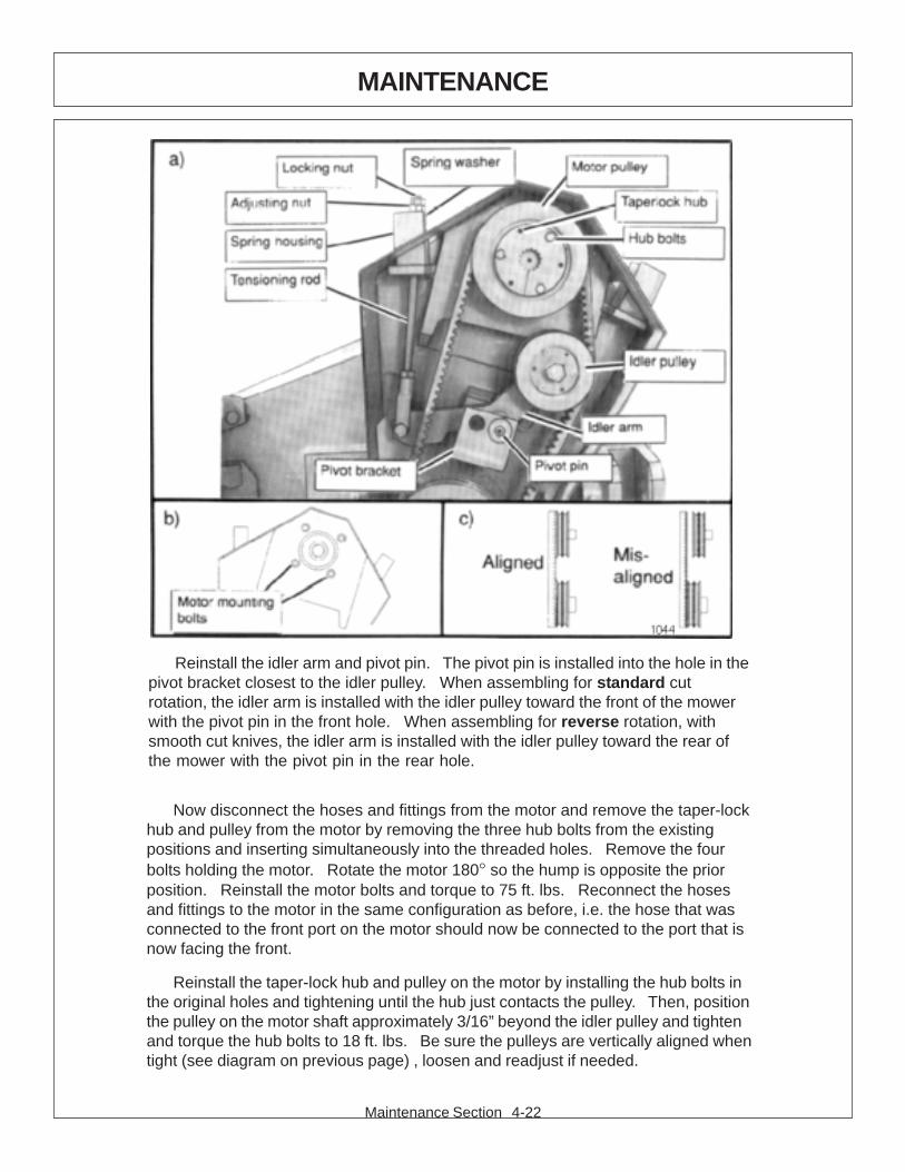
Maintenance Section 4-22
MAINTENANCE
Now disconnect the hoses and fittings from the motor and remove the taper-lockhub and pulley from the motor by removing the three hub bolts from the existingpositions and inserting simultaneously into the threaded holes. Remove the fourbolts holding the motor. Rotate the motor 180° so the hump is opposite the priorposition. Reinstall the motor bolts and torque to 75 ft. lbs. Reconnect the hosesand fittings to the motor in the same configuration as before, i.e. the hose that wasconnected to the front port on the motor should now be connected to the port that isnow facing the front.
Reinstall the taper-lock hub and pulley on the motor by installing the hub bolts inthe original holes and tightening until the hub just contacts the pulley. Then, positionthe pulley on the motor shaft approximately 3/16” beyond the idler pulley and tightenand torque the hub bolts to 18 ft. lbs. Be sure the pulleys are vertically aligned whentight (see diagram on previous page) , loosen and readjust if needed.
Reinstall the idler arm and pivot pin. The pivot pin is installed into the hole in thepivot bracket closest to the idler pulley. When assembling for standard cutrotation, the idler arm is installed with the idler pulley toward the front of the mowerwith the pivot pin in the front hole. When assembling for reverse rotation, withsmooth cut knives, the idler arm is installed with the idler pulley toward the rear ofthe mower with the pivot pin in the rear hole.
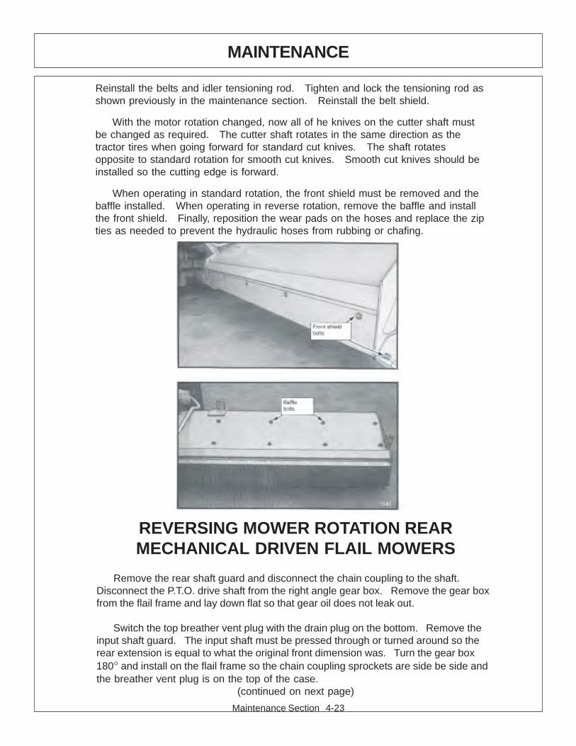
Maintenance Section 4-23
MAINTENANCE
REVERSING MOWER ROTATION REARMECHANICAL DRIVEN FLAIL MOWERS
Remove the rear shaft guard and disconnect the chain coupling to the shaft.Disconnect the P.T.O. drive shaft from the right angle gear box. Remove the gear boxfrom the flail frame and lay down flat so that gear oil does not leak out.
Switch the top breather vent plug with the drain plug on the bottom. Remove theinput shaft guard. The input shaft must be pressed through or turned around so therear extension is equal to what the original front dimension was. Turn the gear box180° and install on the flail frame so the chain coupling sprockets are side be side andthe breather vent plug is on the top of the case.
(continued on next page)
Reinstall the belts and idler tensioning rod. Tighten and lock the tensioning rod asshown previously in the maintenance section. Reinstall the belt shield.
With the motor rotation changed, now all of he knives on the cutter shaft mustbe changed as required. The cutter shaft rotates in the same direction as thetractor tires when going forward for standard cut knives. The shaft rotatesopposite to standard rotation for smooth cut knives. Smooth cut knives should beinstalled so the cutting edge is forward.
When operating in standard rotation, the front shield must be removed and thebaffle installed. When operating in reverse rotation, remove the baffle and installthe front shield. Finally, reposition the wear pads on the hoses and replace the zipties as needed to prevent the hydraulic hoses from rubbing or chafing.
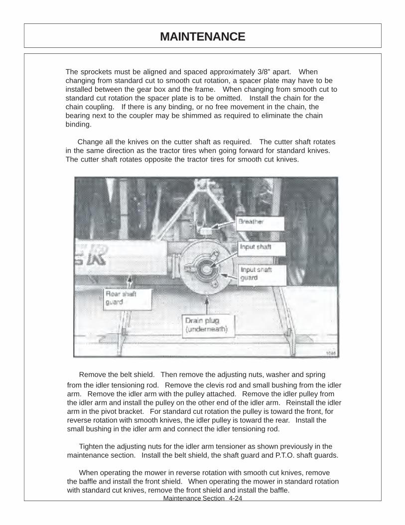
Maintenance Section 4-24
MAINTENANCE
Remove the belt shield. Then remove the adjusting nuts, washer and spring
from the idler tensioning rod. Remove the clevis rod and small bushing from the idlerarm. Remove the idler arm with the pulley attached. Remove the idler pulley fromthe idler arm and install the pulley on the other end of the idler arm. Reinstall the idlerarm in the pivot bracket. For standard cut rotation the pulley is toward the front, forreverse rotation with smooth knives, the idler pulley is toward the rear. Install thesmall bushing in the idler arm and connect the idler tensioning rod.
Tighten the adjusting nuts for the idler arm tensioner as shown previously in themaintenance section. Install the belt shield, the shaft guard and P.T.O. shaft guards.
When operating the mower in reverse rotation with smooth cut knives, removethe baffle and install the front shield. When operating the mower in standard rotationwith standard cut knives, remove the front shield and install the baffle.
The sprockets must be aligned and spaced approximately 3/8” apart. Whenchanging from standard cut to smooth cut rotation, a spacer plate may have to beinstalled between the gear box and the frame. When changing from smooth cut tostandard cut rotation the spacer plate is to be omitted. Install the chain for thechain coupling. If there is any binding, or no free movement in the chain, thebearing next to the coupler may be shimmed as required to eliminate the chainbinding.
Change all the knives on the cutter shaft as required. The cutter shaft rotatesin the same direction as the tractor tires when going forward for standard knives.The cutter shaft rotates opposite the tractor tires for smooth cut knives.

Maintenance Section 4-25
MAINTENANCE
50” BOOM FLAIL KNIFE REPLACEMENT
1 – If knives are damaged or badly worn, they will need to be replaced as a set. Replacinga single knife can cause severe vibration and possible damage to the mower. The knifeshould not be welded on for any reason.
2 - Always replace the knife bolts when replacing the knives. DO NOT REUSE THEKNIFE BOLTS OR NUTS.
3 – Assemble knives, bushings, bolts and nuts as shown in part section of the manual.
4 – Install the locking hex nut so that the flat face of the nut is towards the knife.
4 – apply loctite “271” or equivalent to threads.
5 – Torque nut to 50 ft lbs. Knife must swing freely.
DO NOT re-use the locking hex nuts for mounting the knives. If hexnut become loose, or require removal for knife replacement or anyother reason, they must be discarded and replaced with new nuts.

Maintenance Section 4-26
MAINTENANCE
63” BOOM FLAIL KNIFE REPLACEMENT
1 – If knives are damaged or badly worn, they will need to be replaced as a set. Replacinga single knife can cause severe vibration and possible damage to the mower.
2 – Assemble knives, clevis, bolts and nuts as shown in part section of manual.
3 – Install locking hex nut so that the flat face of nut is towards the knife.
4 – apply loctite “271” or equivalent to threads.
5 – Torque nut to 35 FT. LBS. Knife must swing freely.
DO NOT re-use the locking hex nuts for mounting the knives. If hexnut become loose, or require removal for knife replacement or anyother reason, they must be discarded and replaced with new nuts.
Knives should not be welded on for any reason.
STANDARD OR HEAVY DUTY SIDE OR REARFLAIL KNIFE REPLACEMENT
1 – If knives are damaged or badly worn, they will need to be replaced as a set. Replacinga single knife can cause severe vibration and possible damage to the mower.
2 – Assemble knives, bushings, collars, bolts and nuts as shown in part section ofmanual.
3 – Install locking hex nut so that the flat face of nut is towards the knife.
4 – apply loctite “271” or equivalent to threads.
5 – Torque nut to 35 FT. LBS. Knife must swing freely.
DO NOT re-use the locking hex nuts for mounting the knives. If hexnut become loose, or require removal for knife replacement or anyother reason, they must be discarded and replaced with new nuts.
Knives should not be welded on for any reason.
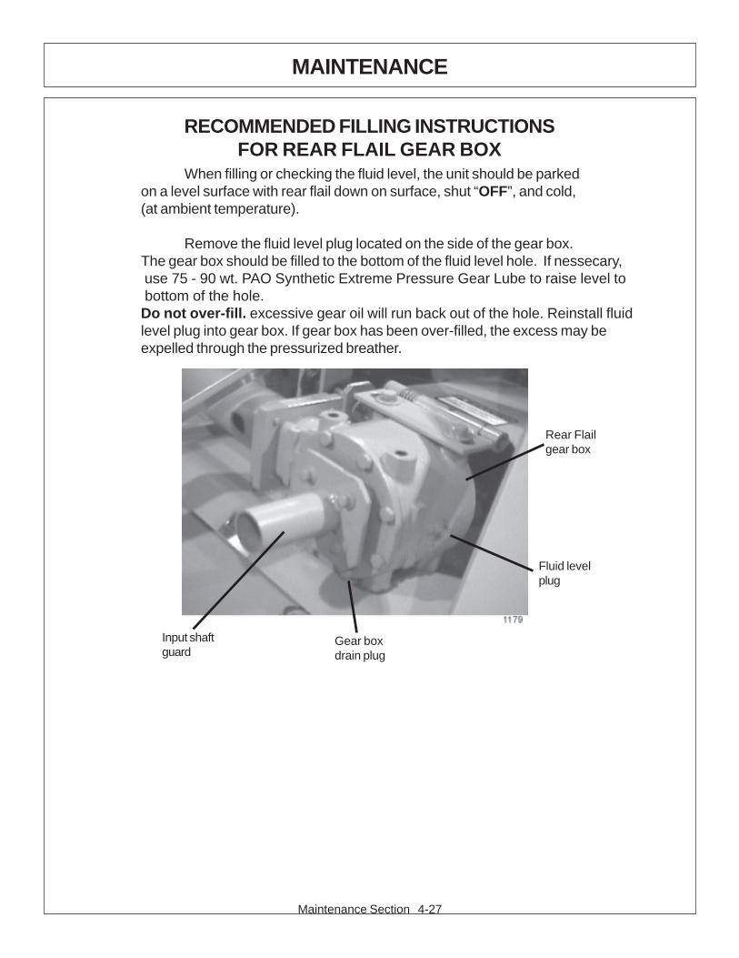
Maintenance Section 4-27
MAINTENANCE
RECOMMENDED FILLING INSTRUCTIONSFOR REAR FLAIL GEAR BOX
Rear Flailgear box
Fluid levelplug
Gear boxdrain plug
Input shaftguard
When filling or checking the fluid level, the unit should be parkedon a level surface with rear flail down on surface, shut “OFF”, and cold,(at ambient temperature).
Remove the fluid level plug located on the side of the gear box.The gear box should be filled to the bottom of the fluid level hole. If nessecary, use 75 - 90 wt. PAO Synthetic Extreme Pressure Gear Lube to raise level to bottom of the hole.Do not over-fill. excessive gear oil will run back out of the hole. Reinstall fluidlevel plug into gear box. If gear box has been over-filled, the excess may beexpelled through the pressurized breather.

Maintenance Section 4-28
MAINTENANCE
DAILY MAINTENANCE SCHEDULEThe following services should be performed daily or every 8 hoursof service, following the detailed maintenance instructions in the operatorsmanual.
______ Pump Drive Shaft: Check for end play in drive shaft / coupler and lubricate at zerks.
______ Crankshaft adapter: If equipped with rubber grommets check conditlion, replace if missing or damaged.
______ Pivot points: Inject grease until it appears at ends.
______ Hydraulic fittings: Check for leaks with paper or cardboard. Tighten fittings or replace hoses immediately.
______ Knives: Inspect for missing or damaged knives, change(onlycomplete sets) as needed.
______ Belts: Check / Tighten / Replace belts as needed.
______ Main Frame / Deck: Unless otherwise specified retorque boltsaccording to torque specifications in thissection.
______ Hydraulic Fluid Level: Add, if required, per fluid recommendations.
______ Rear Flail Drive, Bearing Flange and Shaft Couplers: Grease as instructed in the detailed (if applicable) maintenance section.
______ Cutter Shaft and Ground Roller: Grease as instructed in the detailed maintenance section
Service performed by:_______ Date:____/____/____ HourMeter:__________
Maintenance Section** This page may be copied and used as part of the daily maintenance routine.

PARTSSECTION
FORD 81-8560 SIDE - REAR FLAIL, CAB
Parts Section 5-1
Parts Section 5-2
The following instructions are offered to help eliminate needless delay and error inprocessing purchase orders for the equipment in this manual.
1. The Parts Section is prepared in logical sequence and grouping of parts thatbelong to the basic machine featured in this manual. Part Numbers andDescriptions are given to help locate the parts and quantities required.
2. The Purchase Order must indicate the Name and Address of the person ororganization ordering the parts, who should be charged, and if possible, the serialnumber of the machine for which the parts are being ordered.
3. The purchase order must clearly list the quantity of each part, the completeand correct part number, and the basic name of the part.
4. The manufacturer reserves the right to substitute parts where applicable.
5. Some parts may be unlisted items which are special production items notnormally stocked and are subject to special handling. Request a quotation for suchparts before sending a purchase order.
6. The manufacturer reserves the right to change prices without prior notice.
NOTE: When ordering replacement decals, refer to the part numbers anddescriptions listed in the safety section in the front of this manual.
For maximum safety and to guarantee optimum product reliability,always use genuine Tiger replacement parts. The use of inferiorreplacement parts may cause premature or catastrophic failurewhich could result in serious injury or death.
Direct any questions regarding parts to:
Tiger Corporation3301 N. Louise Ave.
Sioux Falls, SD 571071-800-843-6849 1-605-336-7900
PARTS ORDERING GUIDE

Parts Section 5-3
PARTS SECTION TABLE OF CONTENTS
SECTION ASSEMBLY PAGE
TRACTOR SPECIFIC PARTS:
TRACTOR MOUNT KIT - MAIN FRAME 06100646 5-4
TRACTOR MOUNT KIT - HYDRAULICS 06100646 5-6
LIFT VALVE 06100648 5-8
PUMP GUARD - OPTIONAL 06200342 5-10
SOLENOID VALVE SWITCH WIRING 80155 5-11
PARTS SECTION QUICK INDEX 5-12
COMMON PARTS SECTION: 6-1
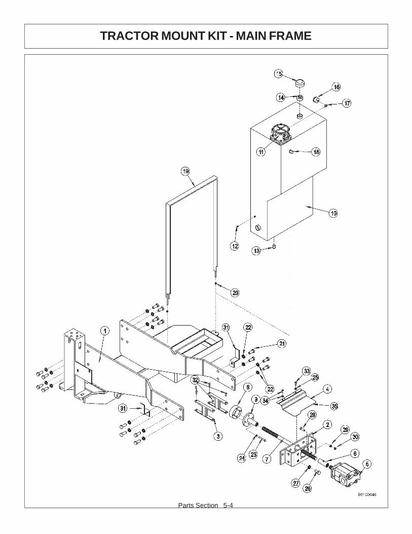
Parts Section 5-4
TRACTOR MOUNT KIT - MAIN FRAME

Parts Section 5-5 R 10-98
TRACTOR MOUNT KIT - MAIN FRAME
ITEM PART NO. QTY. DESCRIPTION
1 32407 1 MAIN FRAME2 32408 1 PUMP MOUNTING BRACKET3 32411 2 BATTERY LIFT BRACKET4 32409 1 DRIVE SHAFT COVER5 23152 1 PUMP6 6T0375B 1 DRV SHFT COUPLING WITH ZERK7 28656 1 PUMP DRIVE SHAFT8 32410 1 DRIVE SHAFT SPACER9 6T0379 1 CRANKSHAFT ADAPTER
28193 AVAIL. RESERVOIR TANK ASSY10 28192D 1 RESERVOIR TANK11 6T0640 1 IN-TANK FILTER ASSY12 6T4197 1 PIPE PLUG13 6T4200 1 PIPE PLUG14 33700 1 REDUCER BUSHING15 31004 1 TANK BREATHER16 6T0649 1 FILTER GUAGE17 TF4888 1 STREET ELBOW18 6T1209 2 TANK SIGHT GLASS19 28191B 1 TANK STRAP20 21627 2 NYLOCK NUT - 3/8"21 31731 16 CAPSCREW - 20MM X 50MM22 24881 16 LOCKWASHER - 20MM23 21688 4 CAPSCREW - 7/16" X 3 1/4"24 21989 4 LOCKWASHER - 7/16"25 32691 1 LOCKWASHER - 10MM26 24860 4 CAPSCREW - 20MM X 40MM27 24881 4 LOCKWASHER - 20MM28 21732 4 CAPSCREW - 1/2" X 1 3/4"29 21990 4 LOCKWASHER - 1/2"30 21725 4 HEX NUT - 1/2"31 32382 2 HOSE BRACKET32 21630 4 CAPSCREW - 3/8" X 1"33 6T2497 1 CAPSCREW - 10MM X 25MM34 EXISTING * EXISTING CAPSCREW WITH LOCKWASHER35 28053 2' TRIM LOCK
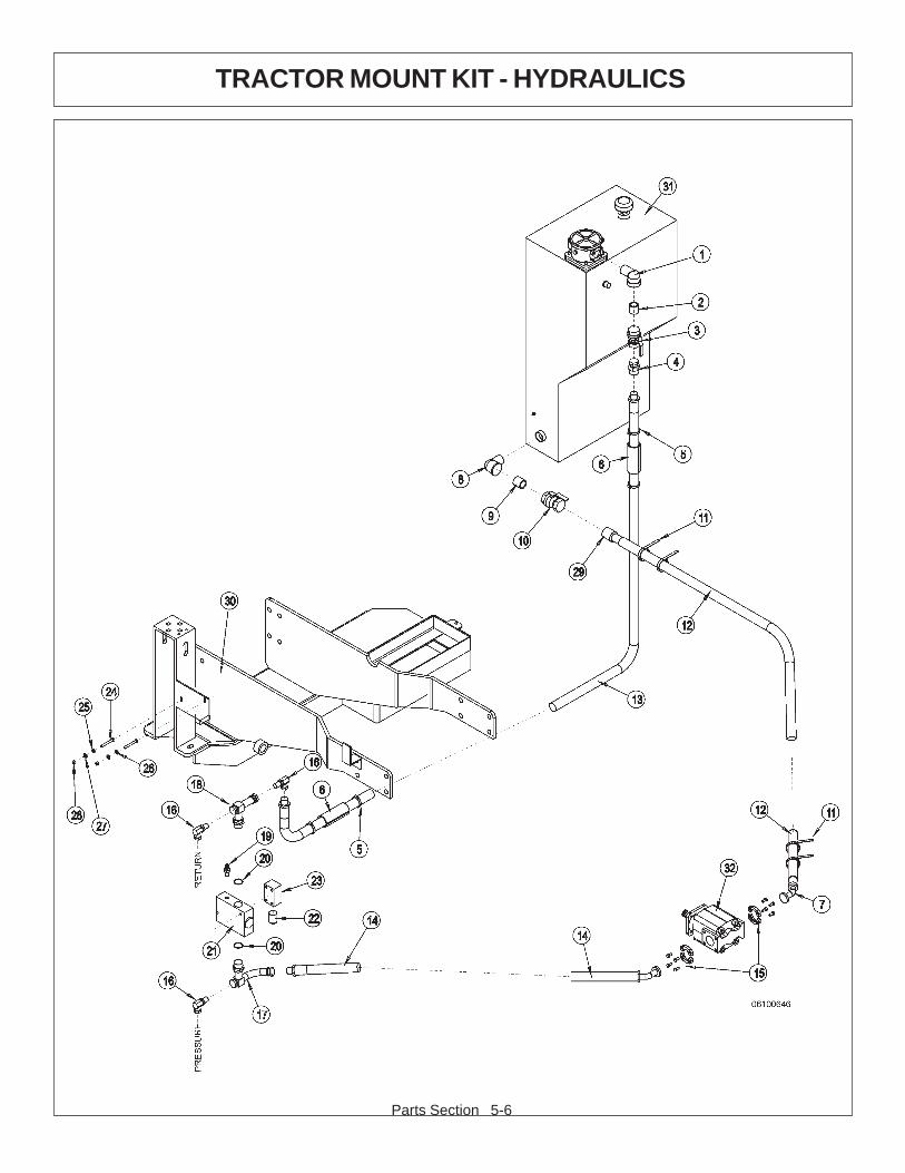
Parts Section 5-6
TRACTOR MOUNT KIT - HYDRAULICS

Parts Section 5-7 R 10-98
TRACTOR MOUNT KIT - HYDRAULICS
ITEM PART NO. QTY. DESCRIPTION
1 6T3601 1 STREET ELBOW2 6T3825 1 NIPPLE3 6T4237 1 BALL VALVE4 22890 1 SWIVEL5 23568 4 HOSE CLAMP6 6T3200 2 SPLIT HOSE7 22631 1 #20 FLANGE - 45 DEG8 6T3612 1 STREET ELBOW9 6T3801 1 NIPPLE10 6T4238 1 BALL VALVE11 6T3018 4 BANDIT CLAMP12 22897 1 SUCTION HOSE13 22858 1 HOSE (MP - MP)14 25223 1 HOSE (MP - 20FLG 45 DEG)15 TF4852 2 #20 FLANGE KIT16 TF4870 3 SWIVEL (MP - FPX)
27907 AVAIL. SOLENOID VALVE ASSEMBLY17 23158 1 PREFORMED TEE18 24030 1 PREFORMED TEE19 6T3910 1 RELIEF VALVE20 6T3904A 2 O-RING21 27360 1 SOLENOID VALVE22 6T3906 1 SOLENOID23 6T3907 1 SOLENOID BLOCK24 21638 2 CAPSCREW - 3/8" x 3"25 6T2665 1 STAR LOCKWASHER - 3/8"26 21988 1 LOCKWASHER - 3/8"27 22016 2 FLATWASHER - 3/8'28 21625 2 HEX NUT - 3/8"29 6T3800 1 NIPPLE30 * REF. MAIN FRAME - REFER TO MAIN FRAME PARTS31 * REF. RESERVOIR TANK - REFER TO MAIN FRAME PART32 * REF. FRONT PUMP - REFER TO MAIN FRAME PARTS
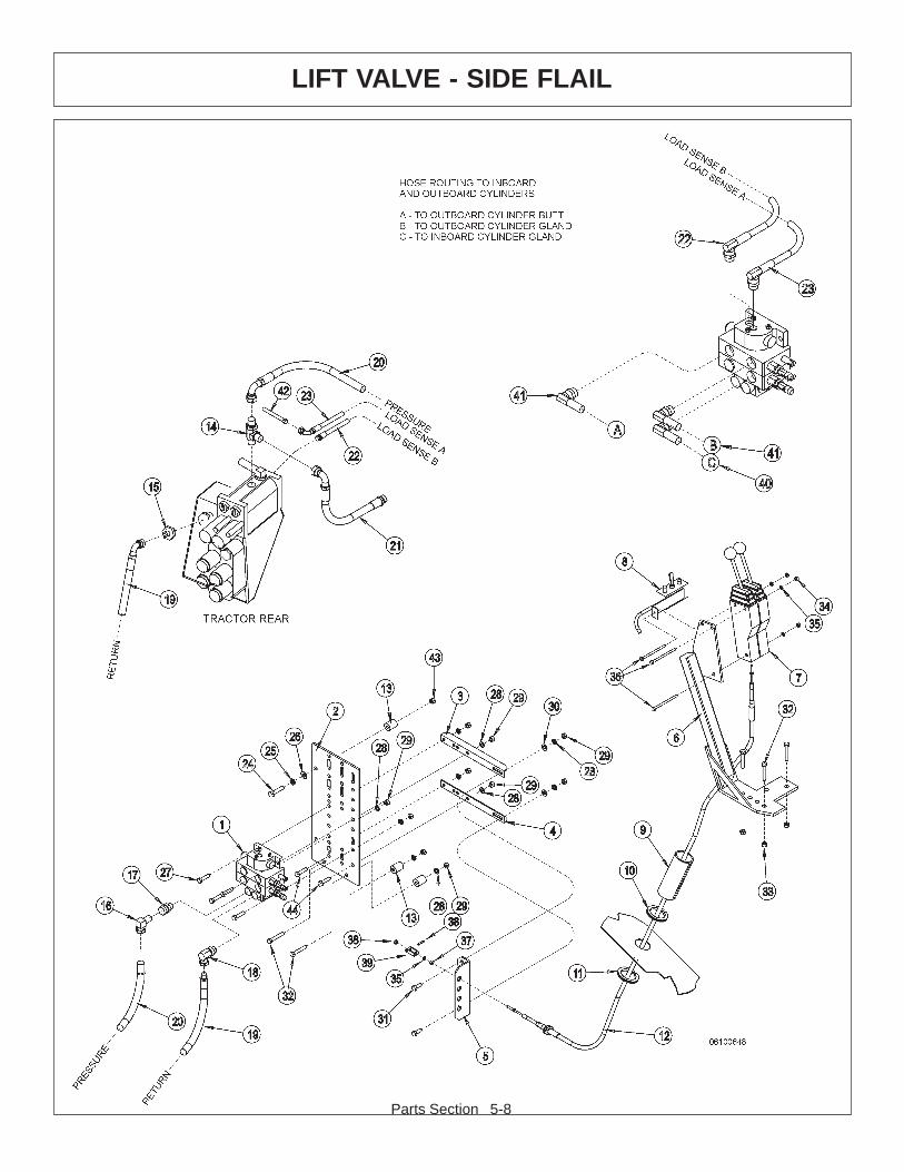
Parts Section 5-8
LIFT VALVE - SIDE FLAIL

Parts Section 5-9
LIFT VALVE - SIDE FLAIL
ITEM PART NO. QTY. DESCRIPTION
1 31322 1 VALVE2 28856C 1 VALVE MOUNTING PLATE3 22148-2D 1 VALVE MOUNTING ANGLE4 22148-1D 1 VALVE MOUNTING ANGLE5 6T4325 1 CABLE REMOTE MOUTING BRACKET6 23865B 1 CABLE CONTROLS MOUNTING BRACKET7 6T1251 2 CABLE CONTROL BOX - 180 DEG8 27401 1 SINGLE SWITCH BOX WITH MTG. BRACKET9 6T3200 1 SPLIT HOSE - SECURE WITH ZIP TIES10 TB3440 1 TRIM LOCK11 28053 1 TRIM LOCK12 31356 2 CABLE - CONTROL13 27082B 3 SPACER14 32440 1 TEE - MALE RUN15 32443 1 ADAPTER16 27145 1 SWIVEL17 TB1094 1 SWIVEL18 TB1095 1 SWIVEL19 32442 1 HOSE20 28921 1 HOSE21 32444 1 HOSE - REPLACES EXISTING HYDRAULIC LINE22 32445 1 HOSE23 32446 1 HOSE24 22254 1 CAPSCREW - 10MM X 50MM25 21989 1 LOCKWASHER - 7/16"26 22017 1 FLATWASHER - 7/16"27 21632 4 CAPSCREW - 3/8" X 1 1/2"28 21988 10 LOCKWASHER - 3/8"29 21625 10 HEX NUT - 3/8'30 22016 2 FLATWASHER - 3/8"31 21630 2 CAPSCREW - 3/8" X 1"32 21635 5 CAPSCREW - 3/8" X 2 1/4"33 21627 3 NYLOCK NUT - 3/8"34 21525 3 HEX NUT - 1/4'35 21986 7 LOCKWASHER - 1/4"36 21542 3 CAPSCREW - 1/4" X 4"37 21500 8 HEX NUT - 1/4" NF38 6T3017 4 ROLL PIN39 6T4411 4 CABLE CLEVIS40 28936 1 HOSE41 28988 2 HOSE42 EXISTING 1 TRACTOR HYDRAULIC LINE43 EXISTING 1 FENDER WELL NUT44 21631 2 CAPSCREW - 3/8" X 1 1/4"
R 10-98
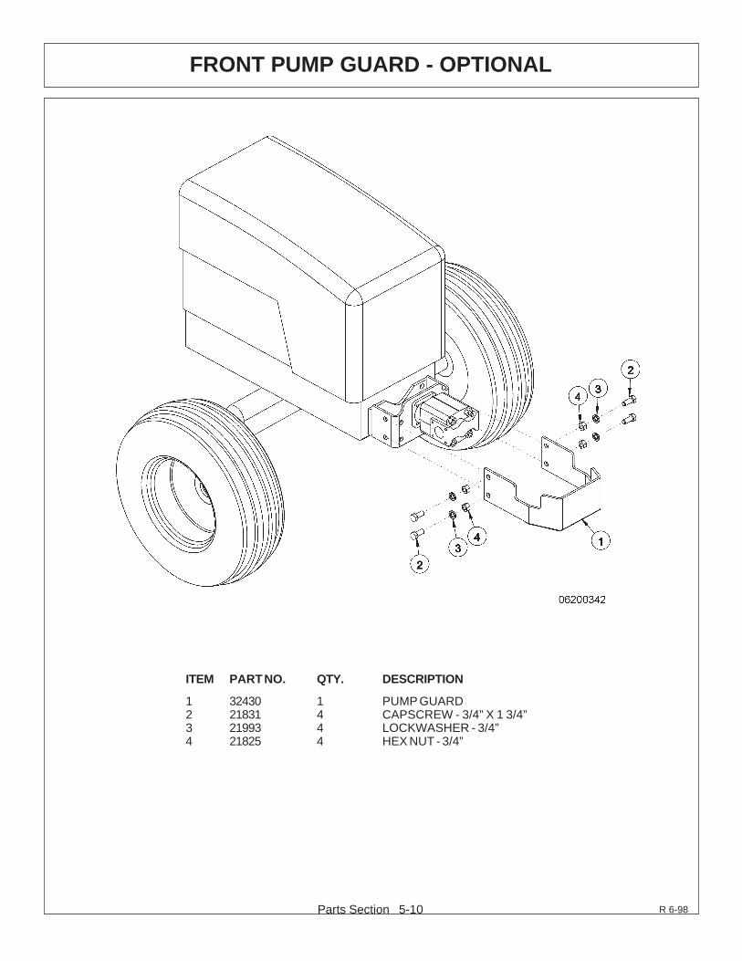
Parts Section 5-10
FRONT PUMP GUARD - OPTIONAL
ITEM PART NO. QTY. DESCRIPTION
1 32430 1 PUMP GUARD2 21831 4 CAPSCREW - 3/4” X 1 3/4”3 21993 4 LOCKWASHER - 3/4”4 21825 4 HEX NUT - 3/4”
R 6-98
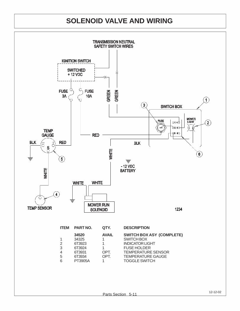
Parts Section 5-1112-12-02
SOLENOID VALVE AND WIRING
ITEM PART NO. QTY. DESCRIPTION
34520 AVAIL SWITCH BOX ASY (COMPLETE)1 34325 1 SWITCH BOX2 6T3923 1 INDICATOR LIGHT3 6T3924 1 FUSE HOLDER4 6T3931 OPT. TEMPERATURE SENSOR5 6T3934 OPT. TEMPERATURE GAUGE6 PT3905A 1 TOGGLE SWITCH

Parts Section 5-12
PARTS QUICK INDEX
This section will assist you in finding the repair parts that you may need for yourTiger mower quickly and easily. The following is a list of common parts and orassemblies followed by the pages in this book where they may be found.
MAIN FRAME AND ATTACHMENTS 5-45-6
HYDRAULIC RESERVOIR AND FITTINGS 5-45-6
HOSES / CABLES 5-65-8
PUMPS / PUMP GUARD 5-45-65-10
VALVES / VALVE HANDLES 5-65-8

HEAVY DUTY SIDE FLAIL MOWER
COMMONPARTS
SECTION

Side Flail Heavy Duty Common Section 6-2
TABLE OF CONTENTS
SECTION ASSEMBLY PAGE
CABLE LIFT ASSEMBLY 6-4
COMBO DRAFT BEAM 6-6
60” STANDARD ROTATION - COMBO 6-8
60” REVERSE ROTATION - COMBO 6-10
75” STANDARD ROTATION - CABLE 6-12
75” REVERSE ROTATION - CABLE 6-14
75” STANDARD ROTATION - COMBO 6-16
75” REVERSE ROTATION - COMBO 6-18
90” STANDARD ROTATION - CABLE 6-20
90” REVERSE ROTATION - CABLE 6-22
90” STANDARD ROTATION - COMBO 6-24
90” REVERSE ROTATION - COMBO 6-26
SIDE FLAIL DRIVE ASSEMBLY 6-28
HYDRAULIC LIFT CYLINDERS 6-30
RESERVOIR TANK FILTER ASSEMBLY 6-34
HUSCO VALVES BREAKDOWN 6-36
FRONT HYDRAULIC PUMP 6-50
FLAIL MOTOR - HIGH PRESSURE 6-52
COOLER ASSEMBLY 6-54
SOLENOID BRAKE VALVE ASSEMBLY 6-56
SOLENOID BRAKE VALVE HYDRO SCHEMATIC 6-57
SIDE FLAIL TRAVEL LOCK 6-58
TRAVEL LOCK LIFT BEAM 6-59
SWITCHBOX
Side Flail Heavy Duty Common Section 6-3
The following instructions are offered to help eliminate needless delay and error inprocessing purchase orders for the equipment in this manual.
1. The Parts Section is prepared in logical sequence and grouping of parts thatbelong to the basic machine featured in this manual. Part Numbers andDescriptions are given to help locate the parts and quantities required.
2. The Purchase Order must indicate the Name and Address of the person ororganization ordering the parts, who should be charged, and if possible, the serialnumber of the machine for which the parts are being ordered.
3. The purchase order must clearly list the quantity of each part, the completeand correct part number, and the basic name of the part.
4. The manufacturer reserves the right to substitute parts where applicable.
5. Some parts may be unlisted items which are special production items notnormally stocked and are subject to special handling. Request a quotation for suchparts before sending a purchase order.
6. The manufacturer reserves the right to change prices without prior notice.
NOTE: When ordering replacement decals, refer to the part numbers anddescriptions listed in the safety section in the front of this manual.
For maximum safety and to guarantee optimum product reliability,always use genuine Tiger replacement parts. The use of inferiorreplacement parts may cause premature or catastrophic failurewhich could result in serious injury or death.
Direct any questions regarding parts to:
Tiger Corporation3301 N. Louise Ave.
Sioux Falls, SD 571071-800-843-6849 1-605-336-7900
PARTS ORDERING GUIDE

Side Flail Heavy Duty Common Section 6-4
CABLE LIFT ASSEMBLY

Side Flail Heavy Duty Common Section 6-5
CABLE LIFT ASSEMBLY
ITEM PART NO. QTY. DESCRIPTION
1 6T0103E OPT. DRAFT BEAM (EXTENDED 6” 4WD)6T0105 OPT. DRAFT BEAM (STD WITH TRAVEL LOCK)6T0108 OPT. DRAFT BEAM (30 LB CHANNEL, 45 3/8”)
2 6T0150 1 CYLINDER 3” X 18”3 6T0151R 1 HYD. CYLINDER 3” X 10”4 6T0100 1 LOWER SHEAVE BRACKET5 6T0101 1 UPPER SHEAVE BRACKET6 33768 2 SHEAVE7 6T0110 1 LIFT CABLE (STD 1/2” X 87 1/2”)
6T0110E OPT. LIFT CABLE (EXTENDED 6” 4WD)6T0110L OPT. LIFT CABLE (EXTENDED 15”)
8 6T0115 1 TURN BUCKLE9 6T0112 1 SHACKLE WITH PIN10 6T2999 1 OUTER DRAFT BEAM PIN 1 1/2” X 14 1/2”11 6T3001 1 INNER DRAFT BEAM PIN 1 1/2” X 15 3/4”12 6T3002 1 CYLINDER PIN 1” X 7 5/8”13 TB1033 2 CLEVIS PIN 1” X 4”14 6T3004 2 R - CLIP 3/16”15 6T3010 1 UPPER SHEAVE PIN WITH ZERK 3/4” X 3”16 6T3009 1 LOWER SHEAVE PIN WITH ZERK 3/4” X 2 1/2”17 27849 2 R - CLIP 3/16”18 6T2272 1 SET SCREW 3/8” X 1/2”19 6T3211 1 GREASE ZERK 1/8” STRAIGHT20 21836 1 CAPSCREW 3/4” X 3”21 21688 2 CAPSCREW 7/16” X 3 1/4”22 21825 2 HEX NUT 3/4”23 21675 2 HEX NUT 7/16”24 22023 2 FLAT WASHER 1”25 21989 2 LOCK WASHER 7/16”26 6T0104N 2 SHEAVE PIN BUSHING 1” OD X 3/4” ID27 21833 1 CAPSCREW 3/4” X 2 1/4”28 22021 1 FLAT WASHER 3/4”29 21993 1 LOCK WASHER 3/4”30 06537021 4 ROLL PIN31 6T0106 1 TRAVEL LOCK BRACKET32 6T4258 2 BREATHER 1/2”33 34396 2 RESTRICTOR34 34244 2 ELBOW FITTING 1/2”35 06700095 1 SPACER37 * REF. MAIN FRAME REFER TO TRACTOR PARTS SECTION

Side Flail Heavy Duty Common Section 6-6
COMBO DRAFT BEAM

Side Flail Heavy Duty Common Section 6-7
COMBO DRAFT BEAM
ITEM PART NO. QTY. DESCRIPTION
1 28955D 1 COMBO DRAFT BEAM - HEAVY DUTY2 6T0151R 1 HYD. CYLINDER 3” X 10”3 25343 1 HYD. CYLINDER 3” X 11.5”4 TF4500A 1 PIVOT ARM5 TF4507B 1 RIGHT LINKAGE ARM6 TF4506B 1 LEFT LINKAGE ARM7 TF4514 2 PIN, HEAD PIVOT8 6T3001 1 PIN, BEAM PIVOT9 TF4519 2 PIN, LINKAGE10 TB1033 3 PIN, CLEVIS11 06537021 6 ROLLPIN12 6T3002A 1 PIN, LIFT CYLINDER13 6T3004 2 R-CLIP HAIRPIN14 22023 2 FLATWASHER 1”15 TB3010 6 BUSHING 1”16 22847 2 BOSS, LINKAGE PIN17 22076 1 SPACER, HYD. CYLINDER 1”(AS NEEDED)18 22077 1 SPACER, HYD. CYLINDER 1/2”(AS NEEDED)19 6T3207 5 GREASE ZERK 1/4”20 6T3211 3 GREASE ZERK 1/8”21 6T4258 1 BREATHER 1/2”23 34244 3 ELBOW FITTING 1/2”24 34396 3 SWIVEL RESTRICTOR27 21688 3 CAPSCREW 7/16” X 3 1/4”28 21989 3 LOCKWASHER 7/16”29 21675 3 HEX NUT 7/16”30 21635 2 CAPSCREW 3/8” X 2 1/4”31 21988 2 LOCKWASHER 3/8”32 21625 2 HEX NUT 3/8”33 21831 1 CAPSCREW 3/4” X 1 3/4”34 21825 1 HEX NUT 3/4”35 06700095 1 SPACER36 * REF REFER TO MAIN FRAME
NOTE: ITEM 35 IS USED ON THE GLAND END OF ITEM 2 (AS NEEDED)
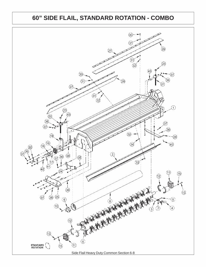
Side Flail Heavy Duty Common Section 6-8
60” SIDE FLAIL, STANDARD ROTATION - COMBO

Side Flail Heavy Duty Common Section 6-9
60” SIDE FLAIL, STANDARD ROTATION - COMBO
ITEM P/N QTY DESCRIPTION
1 33913 1 BONNET 60" COMBO2 TF1802A 1 BAFFLE,FLAIL,60" HD,STC
TF1807A 1 CUTTERSHAFT,ASSY,60" HD,STC3 21677 40 NYLOCK NUT,7/16 NC4 33714 80 KNIFE,FLAIL,STANDARD5 34011 40 CAPSCREW,7/16x3 7/16,NC GR86 TF1807 1 CUTTERSHAFT,60" HD7 TF1020 40 KNIFE MTG CLEVIS,FLAIL8 30277 1 GROUND ROLLER 60”9 TF1045B 2 STUB SHAFT,GROUND ROLLER10 6T2330 8 CAPSCREW,SKT HD,7/16X1-1/2NC11 TF1018 2 BEARING,FLANGE,2-3/16
06200347 * STRING GUARD,KIT,HD(ITEMS 12,13,15)12 31204 2 STRING GUARD, HD13 06530217 8 CAPSCREW,1/2 X 2,NC,L915 06533006 12 FLATWASHER,1/2,SAE,L916 06520028 2 BEARING,FLANGE,1 3/8,GRNDRLR17 06520029 2 O-RING,2 3/4x3/32,AS568A-14818 06520027 2 CAP,BEARING,GRNDRLR19 TF4333A 2 GROUND ROLLER ADJ,BRKT20 TF4334 1 ROD,GROUND ROLLER ADJ,RT21 TF4335 1 ROD,GROUND ROLLER ADJ,LF22 TF4336 4 PLATE,GROUND ROLLER LOCK23 21399 2 HEX NUT,3/4 (ACME) BULK24 TF1040 1 GUARD,CUTTER SHAFT25 TF4371 1 SKID SHOE,L/PROFILE-OUTER26 23272A 1 SKID SHOE,T3F,INNER27 TF1803 2 BAR,FLAP,TSF/TRF 6028 TF1804 1 FLAP,DEFLECTOR,TSF 6029 06520240 1 FLAP,60",FRONT30 21632 30 CAPSCREW,3/8 X 1-1/2 NC31 22016 60 FLATWASHER,3/832 21625 40 HEX NUT,3/8 NC33 6T2283 10 CARRIAGE BOLT,3/8 X 1 NC34 6T2615 10 WASHER,FENDER 3/835 21732 2 CAPSCREW,1/2 X 1-3/4 NC36 21990 23 LOCKWASHER,1/237 21725 23 HEX NUT,1/2 NC38 6T2331 8 CAPSCREW,SKT HD,7/16 X 1 NC39 21730 6 CAPSCREW,1/2 X 1-1/4 NC40 23293 3 PLOW,BOLT,1/2 X 1-3/4 NC41 06530001 12 CAPSCREW,SKT HD,8-32x1/2,SS42 6T2291 8 PLOW BOLT,1/2 X 2 NC GR543 21731 4 CAPSCREW,1/2 X 1-1/2 NC

Side Flail Heavy Duty Common Section 6-10
60” SIDE FLAIL, REVERSE ROTATION - COMBO

Side Flail Heavy Duty Common Section 6-11
60” SIDE FLAIL, REVERSE ROTATION - COMBO
ITEM P/N QTY DESCRIPTION
1 33913 1 BONNET 60" COMBO2 TF1802A 1 BAFFLE,FLAIL,60" HD,STC
TF1807A 1 CUTTERSHAFT,ASSY,60" HD,STC3 21677 40 NYLOCK NUT,7/16 NC4 33714 80 KNIFE,FLAIL,STANDARD5 34011 40 CAPSCREW,7/16x3 7/16,NC GR86 TF1807 1 CUTTERSHAFT,60" HD7 TF1020 40 KNIFE MTG CLEVIS,FLAIL8 30277 1 GROUND ROLLER 60”9 TF1045B 2 STUB SHAFT,GROUND ROLLER10 6T2330 8 CAPSCREW,SKT HD,7/16X1-1/2NC11 TF1018 2 BEARING,FLANGE,2-3/16
06200347 * STRING GUARD,KIT,HD(ITEMS 12,13,15)12 31204 2 STRING GUARD, HD14 TF1019F 40 KNIFE,FLAIL (SMOOTH CUT)13 06530217 8 CAPSCREW,1/2 X 2,NC,L915 06533006 12 FLATWASHER,1/2,SAE,L916 06520028 2 BEARING,FLANGE,1 3/8,GRNDRLR17 06520029 2 O-RING,2 3/4x3/32,AS568A-14818 06520027 2 CAP,BEARING,GRNDRLR19 TF4333A 2 GROUND ROLLER ADJ,BRKT20 TF4334 1 ROD,GROUND ROLLER ADJ,RT21 TF4335 1 ROD,GROUND ROLLER ADJ,LF22 TF4336 4 PLATE,GROUND ROLLER LOCK23 21399 2 HEX NUT,3/4 (ACME) BULK24 TF1040 1 GUARD,CUTTER SHAFT25 TF4371 1 SKID SHOE,L/PROFILE-OUTER26 23272A 1 SKID SHOE,T3F,INNER27 TF1803 1 BAR,FLAP,TSF/TRF 6028 TF1804 1 FLAP,DEFLECTOR,TSF 6029 06520240 1 FLAP,60",FRONT30 21632 30 CAPSCREW,3/8 X 1-1/2 NC31 22016 60 FLATWASHER,3/832 21625 40 HEX NUT,3/8 NC33 6T2283 10 CARRIAGE BOLT,3/8 X 1 NC34 6T2615 10 WASHER,FENDER 3/835 21732 2 CAPSCREW,1/2 X 1-3/4 NC36 21990 23 LOCKWASHER,1/237 21725 23 HEX NUT,1/2 NC38 6T2331 8 CAPSCREW,SKT HD,7/16 X 1 NC39 21730 6 CAPSCREW,1/2 X 1-1/4 NC40 23293 3 PLOW,BOLT,1/2 X 1-3/4 NC41 06530001 12 CAPSCREW,SKT HD,8-32x1/2,SS42 6T2291 8 PLOW BOLT,1/2 X 2 NC GR543 21731 4 CAPSCREW,1/2 X 1-1/2 NC44 TF1801 1 TRASH GUARD,60REV ROT-HD45 22018 1 FLATWASHER,1/2,WIDE46 21727 1 NYLOCK NUT,1/2 NC
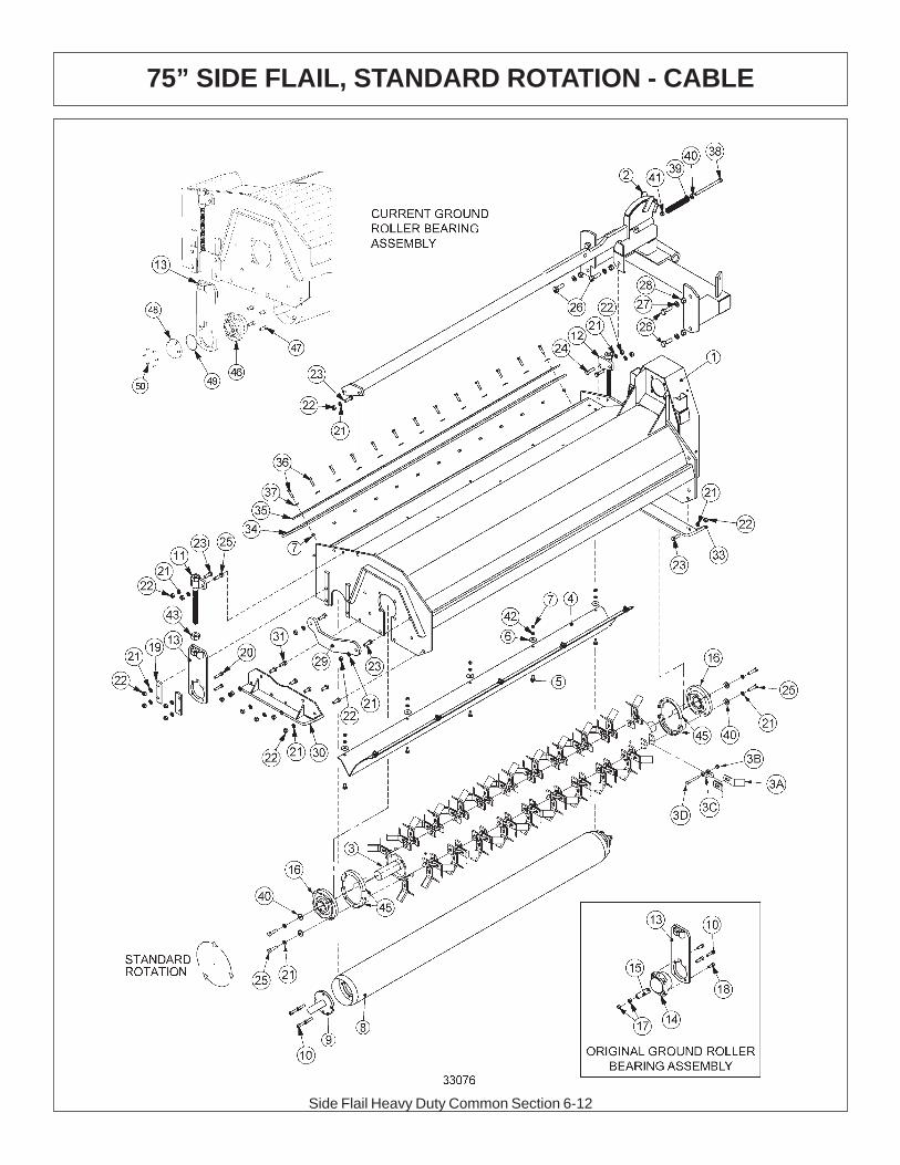
Side Flail Heavy Duty Common Section 6-12
75” SIDE FLAIL, STANDARD ROTATION - CABLE

Side Flail Heavy Duty Common Section 6-13
75” SIDE FLAIL, STANDARD ROTATION - CABLE
ITEM P/N QTY DESCRIPTION
1 22032 1 BONNET,75,HD,TSF2 21298C 1 MOUNTING FRAME3 TF1002A 1 CUTTERSHAFT,ASSY,75" HD,STC3A 33714 80 KNIFE,FLAIL,STANDARD3B 21677 40 NYLOCK NUT,7/16” NC3C TF1020 40 KNIFE MTG CLEVIS,FLAIL3D 34011 40 KNIFE MTG BOLT,FLAIL4 TF1402A 1 BAFFLE,FLAIL,75" HD,STC5 6T2283 10 CARRIAGE BOLT,3/8" X 1"NC6 6T2615 10 WASHER,FENDER 3/8"7 21625 23 HEX NUT,3/8",NC8 28738 1 GROUND ROLLER9 TF1045B 2 GRND ROLLER STUB SHAFT10 6T2330 12 CAPSCREW, 7/16 x 1 1/2, SOCKET HEAD11 TF4334 1 ROD,GROUND ROLLER ADJ,RT12 TF4335 1 ROD,GROUND ROLLER ADJ,LF13 TF4333A 2 GROUND ROLLER ADJ BRK14 TF1022S 2 BEARING,FLANGE,1-3/8"15 30565 2 BEARING CAP KEEPER16 TF1018 2 BEARING,FLANGE,2-3/16"17 24701 4 HEX NUT, 7/16" NC (STOVER NUT)18 6T2331 4 CAPSCREW, 7/16 x 1, SOCKET HEAD19 TF4336 4 CLAMPING BLOCK, LH20 6T2291 8 PLOW BOLT,1/2" X 2" NC21 21990 31 LOCKWASHER, 1/2"22 21725 23 HEX NUT, 1/2" NC23 21731 6 CAPSCREW, 1/2 X 1 1/2,NC24 21732 2 CAPSCREW, 1/2 x 1 3/4,NC25 21733 9 CAPSCREW, 1/2 x 2,NC26 21783 5 CAPSCREW, 5/8 x 2,NC27 21992 5 LOCKWASHER, 5/828 21775 5 HEX NUT, 5/829 TF1040 1 GUARD, CUTTER SHAFT30 TF4371 1 SKID SHOE,L/PROFILE - OUTER31 21730 6 CAPSCREW, 1/2 X 1 1/4,NC33 TF4365 1 SKID SHOE,L/PROFILE - INNER34 TF1016 1 FLAP,DEFLECTOR,TSF/TRF 7535 TF1029 1 FLAP RETAINING BAR36 21632 13 CAPSCREW,3/8" X 1-1/2" NC37 22016 13 FLATWASHER,3/8"38 21745 1 CAPSCREW, 1/2 x 7,NC39 27005 1 SPRING, PUSHOFF, SIDE RTRY40 27938 3 BUSHING,MACH,1ODx1/2IDx14GA.41 21727 1 NYLOCK NUT, 1/2”42 21988 10 LOCKWASHER, 3/8"43 21399 2 HEX NUT, 3/4" (ACME THRD)45 31204 2 STRING GUARD, HD46 06520028 2 BEARING,FLANGE, 1 3/8”47 6T2331 8 CAPSCREW, 7/16” X 1”, SOCKET HEAD48 06520027 2 CAP,BEARING, GRND ROLLER49 06520029 2 O-RING,2 3/4" X 3/32”50 06530001 12 CAPSCREW, SKT HD
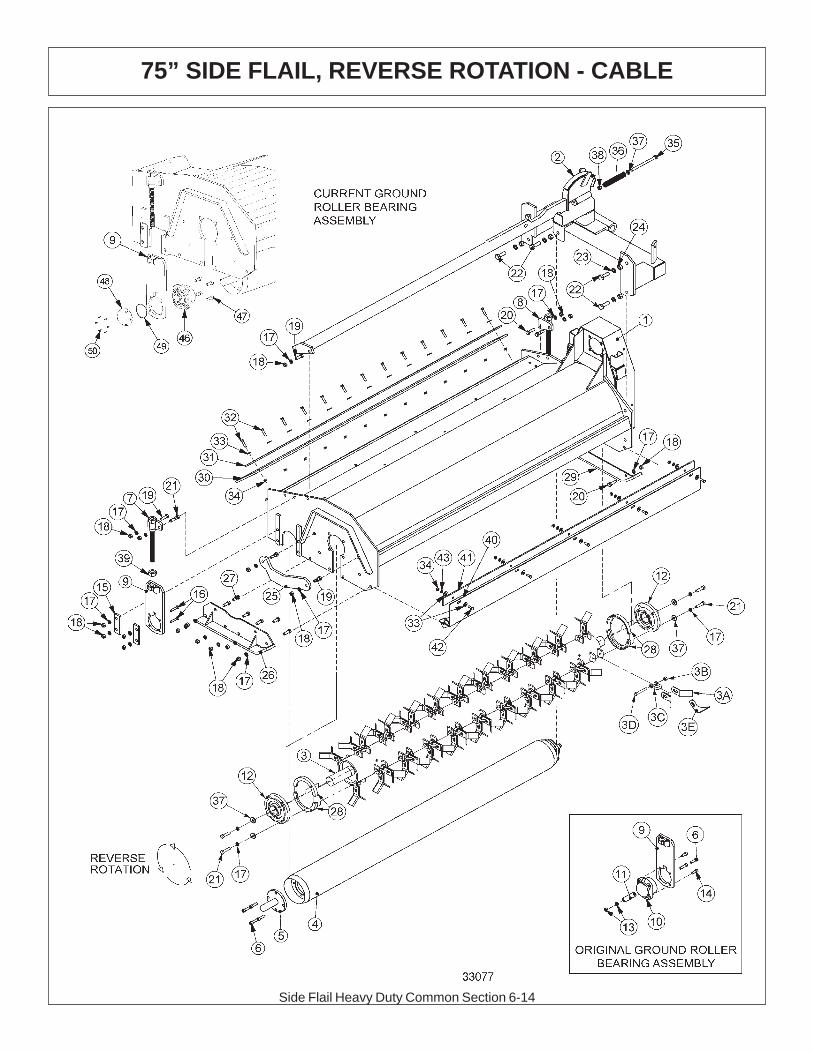
Side Flail Heavy Duty Common Section 6-14
75” SIDE FLAIL, REVERSE ROTATION - CABLE

Side Flail Heavy Duty Common Section 6-15
75” SIDE FLAIL, REVERSE ROTATION - CABLE
ITEM P/N QTY DESCRIPTION
1 22032 1 BONNET,75,HD,TSF2 21298C 1 MOUNTING FRAME3 TF1002A 1 CUTTERSHAFT,ASSY,75" HD,STC3A 33714 80 KNIFE,FLAIL,STANDARD3B 21677 40 NYLOCK NUT,7/16” NC3C TF1020 40 KNIFE MTG CLEVIS,FLAIL3D 34011 40 KNIFE MTG BOLT,FLAIL3E TF1019F 40 KNIFE,FLAIL (SMOOTH CUT)4 28738 1 GROUND ROLLER5 TF1045B 2 GRND ROLLER STUB SHAFT6 6T2330 12 CAPSCREW, 7/16 x 1 1/2, SOCKET HEAD7 TF4334 1 ROD,GROUND ROLLER ADJ,RT8 TF4335 1 ROD,GROUND ROLLER ADJ,LF9 TF4333A 2 GROUND ROLLER ADJ BRK10 TF1022S 2 BEARING,FLANGE,1-3/8"11 30565 2 BEARING CAP KEEPER12 TF1018 2 BEARING,FLANGE,2-3/16"13 24701 4 HEX NUT, 7/16" NC (STOVER NUT)14 6T2331 4 CAPSCREW, 7/16 x 1, SOCKET HEAD15 TF4336 4 CLAMPING BLOCK, LH16 6T2291 8 PLOW BOLT,1/2" X 2" NC17 21990 31 LOCKWASHER, 1/2"18 21725 23 HEX NUT, 1/2" NC19 21731 6 CAPSCREW, 1/2 X 1 1/2,NC20 21732 3 CAPSCREW, 1/2 x 1 3/4,NC21 21733 5 CAPSCREW, 1/2 x 2,NC22 21783 5 CAPSCREW, 5/8 x 2,NC23 21992 5 LOCKWASHER, 5/824 21775 5 HEX NUT, 5/825 TF1040 1 GUARD, CUTTER SHAFT26 TF4371 1 SKID SHOE,L/PROFILE - OUTER27 21730 5 CAPSCREW, 1/2 X 1 1/4,NC28 31204 2 STRING GUARD, HD29 TF4365 1 SKID SHOE,L/PROFILE - INNER30 TF1016 1 FLAP,DEFLECTOR,TSF/TRF 7531 TF1029 1 FLAP RETAINING BAR32 21632 13 CAPSCREW,3/8" X 1-1/2" NC33 22016 23 FLATWASHER,3/8"34 21625 18 HEX NUT,3/8",NC35 21745 1 CAPSCREW, 1/2 x 7,NC36 27005 1 SPRING, PUSHOFF, SIDE RTRY37 27938 9 BUSHING,MACH,1ODx1/2IDx14GA.38 21727 1 NYLOCK NUT, 1/239 21399 2 HEX NUT, 3/4" (ACME THRD)40 TF1403 1 FRONT TRASH GUARD41 25461 1 MOUNTING BAR42 21630 5 CAPSCREW, 3/8 x 1,NC43 21988 5 LOCKWASHER, 3/8"46 06520028 2 BEARING,FLANGE, 1 3/8”47 6T2331 8 CAPSCREW, 7/16” X 1”, SOCKET HEAD48 06520027 2 CAP,BEARING, GRND ROLLER49 06520029 2 O-RING,2 3/4" X 3/32”50 06530001 12 CAPSCREW, SKT HD
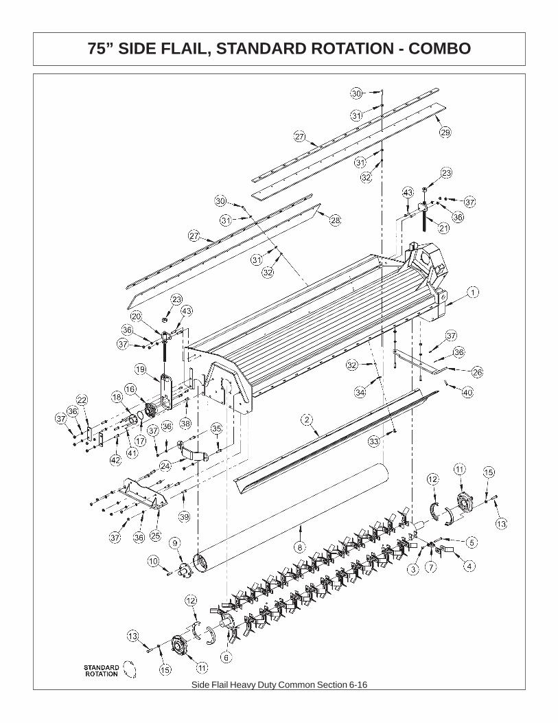
Side Flail Heavy Duty Common Section 6-16
75” SIDE FLAIL, STANDARD ROTATION - COMBO

Side Flail Heavy Duty Common Section 6-17
75” SIDE FLAIL, STANDARD ROTATION - COMBO
ITEM P/N QTY DESCRIPTION
1 21499A 1 BONNET,75,HD,T3F,RT2 TF1402A 1 BAFFLE,FLAIL,75HD,STD ROT
TF1002A 1 CUTSHFT ASSY,75HD,STD KNIVES3 21677 48 NYLOCK NUT,7/16 NC4 33714 96 KNIFE,FLAIL,STANDARD5 34011 48 CAPSCREW,7/16x3 7/16,NC GR86 TF1002 1 CUTTERSHAFT,90,HD7 TF1020 48 KNIFE MTG CLEVIS,FLAIL8 28738 1 GROUND ROLLER,759 TF1045B 2 STUB SHAFT,GROUND ROLLER10 6T2330 8 CAPSCREW,SKT HD,7/16X1-1/2NC11 TF1018 2 BEARING,FLANGE,2-3/16
06200347 * STRING GUARD,KIT,HD(ITEMS 12,13,15)12 31204 2 STRING GUARD, HD13 06530217 8 CAPSCREW,1/2 X 2,NC,L915 06533006 12 FLATWASHER,1/2,SAE,L916 06520028 2 BEARING,FLANGE,1 3/8,GRNDRLR17 06520029 2 O-RING,2 3/4x3/32,AS568A-14818 06520027 2 CAP,BEARING,GRNDRLR19 TF4333A 2 GROUND ROLLER ADJ,BRKT20 TF4334 1 ROD,GROUND ROLLER ADJ,RT21 TF4335 1 ROD,GROUND ROLLER ADJ,LF22 TF4336 4 PLATE,GROUND ROLLER LOCK23 21399 2 HEX NUT,3/4 (ACME) BULK24 TF1040 1 GUARD,CUTTER SHAFT25 TF4371 1 SKID SHOE,L/PROFILE-OUTER26 23272A 1 SKID SHOE,T3F,INNER27 TF1029 2 BAR,FLAP,TSF/TRF 7528 TF1016 1 FLAP,DEFLECTOR,TSF/TRF 7529 06520242 1 FLAP,75",FRONT30 21632 30 CAPSCREW,3/8 X 1-1/2 NC31 22016 60 FLATWASHER,3/832 21625 40 HEX NUT,3/8 NC33 6T2283 10 CARRIAGE BOLT,3/8 X 1 NC34 6T2615 10 WASHER,FENDER 3/835 21732 2 CAPSCREW,1/2 X 1-3/4 NC36 21990 23 LOCKWASHER,1/237 21725 23 HEX NUT,1/2 NC38 6T2331 8 CAPSCREW,SKT HD,7/16 X 1 NC39 21730 6 CAPSCREW,1/2 X 1-1/4 NC40 23293 3 PLOW,BOLT,1/2 X 1-3/4 NC41 06530001 12 CAPSCREW,SKT HD,8-32x1/2,SS42 6T2291 8 PLOW BOLT,1/2 X 2 NC GR543 21731 4 CAPSCREW,1/2 X 1-1/2 NC
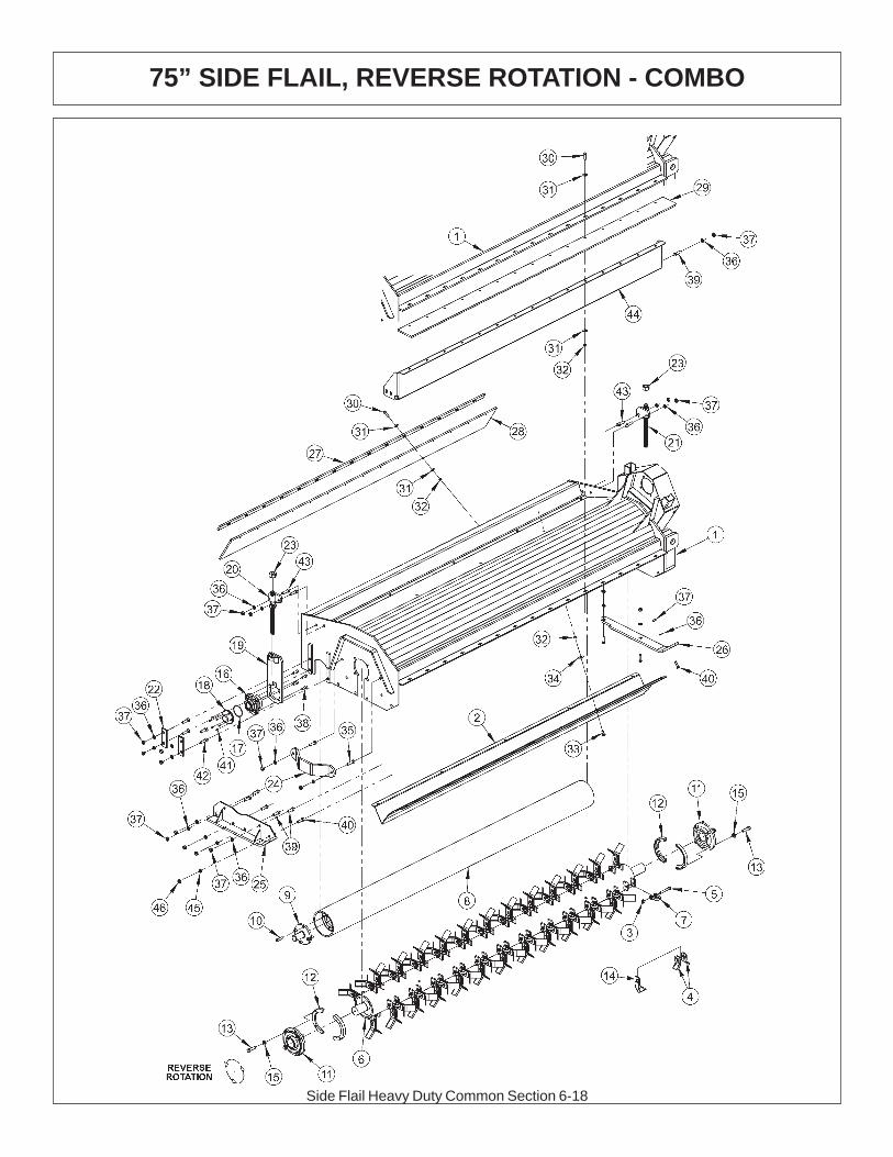
Side Flail Heavy Duty Common Section 6-18
75” SIDE FLAIL, REVERSE ROTATION - COMBO

Side Flail Heavy Duty Common Section 6-19
75” SIDE FLAIL REVESE ROTATION - COMBO
ITEM P/N QTY DESCRIPTION
1 21499A 1 BONNET,75,HD,T3F,RT2 TF1402A 1 BAFFLE,FLAIL,75HD (STANDARD ROTATION ONLY)
TF1002A 1 CUTSHFT ASSY,75HD,STD KNIVE3 21677 48 NYLOCK NUT,7/16 NC4 33714 96 KNIFE,FLAIL,STANDARD5 34011 48 CAPSCREW,7/16x3 7/16,NC GR86 TF1002 1 CUTTERSHAFT,75,HD7 TF1020 48 KNIFE MTG CLEVIS,FLAIL8 28738 1 GROUND ROLLER,759 TF1045B 2 STUB SHAFT,GROUND ROLLER10 6T2330 8 CAPSCREW,SKT HD,7/16X1-1/2NC11 TF1018 2 BEARING,FLANGE,2-3/16
06200347 * STRING GUARD,KIT,HD(ITEMS 12,13,15)12 31204 2 STRING GUARD, HD14 TF1019F 48 KNIFE,FLAIL (SMOOTH CUT)13 06530217 8 CAPSCREW,1/2 X 2,NC,L915 06533006 12 FLATWASHER,1/2,SAE,L916 06520028 2 BEARING,FLANGE,1 3/8,GRNDRLR17 06520029 2 O-RING,2 3/4x3/32,AS568A-14818 06520027 2 CAP,BEARING,GRNDRLR19 TF4333A 2 GROUND ROLLER ADJ,BRKT20 TF4334 1 ROD,GROUND ROLLER ADJ,RT21 TF4335 1 ROD,GROUND ROLLER ADJ,LF22 TF4336 4 PLATE,GROUND ROLLER LOCK23 21399 2 HEX NUT,3/4 (ACME) BULK24 TF1040 1 GUARD,CUTTER SHAFT25 TF4371 1 SKID SHOE,L/PROFILE-OUTER26 23272A 1 SKID SHOE,T3F,INNER27 TF1029 1 BAR,FLAP,TSF/TRF 7528 TF1016 1 FLAP,DEFLECTOR,TSF/TRF 7529 06520242 1 FLAP,75",FRONT30 21632 30 CAPSCREW,3/8 X 1-1/2 NC31 22016 60 FLATWASHER,3/832 21625 40 HEX NUT,3/8 NC33 6T2283 10 CARRIAGE BOLT,3/8 X 1 NC34 6T2615 10 WASHER,FENDER 3/835 21732 2 CAPSCREW,1/2 X 1-3/4 NC36 21990 23 LOCKWASHER,1/237 21725 23 HEX NUT,1/2 NC38 6T2331 8 CAPSCREW,SKT HD,7/16 X 1 NC39 21730 6 CAPSCREW,1/2 X 1-1/4 NC40 23293 3 PLOW,BOLT,1/2 X 1-3/4 NC41 06530001 12 CAPSCREW,SKT HD,8-32x1/2,SS42 6T2291 8 PLOW BOLT,1/2 X 2 NC GR543 21731 4 CAPSCREW,1/2 X 1-1/2 NC44 TF1403 1 TRASH GUARD,75REV ROT-HD45 22018 1 FLATWASHER,1/2,WIDE46 21727 1 NYLOCK NUT,1/2 NC
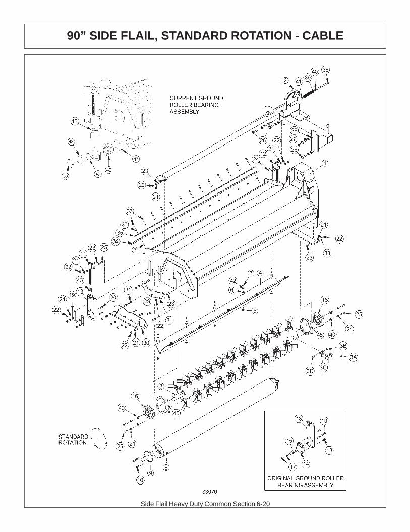
Side Flail Heavy Duty Common Section 6-20
90” SIDE FLAIL, STANDARD ROTATION - CABLE

Side Flail Heavy Duty Common Section 6-21
90” SIDE FLAIL, STANDARD ROTATION - CABLE
ITEM P/N QTY DESCRIPTION
1 27047 1 BONNET,90,HD,TSF2 27048A 1 MOUNTING FRAME3 TF1102A 1 CUTTERSHAFT,ASSY,90" HD,STC3A 33714 80 KNIFE,FLAIL,STANDARD3B 21677 40 NYLOCK NUT,7/16” NC3C TF1020 40 KNIFE MTG CLEVIS,FLAIL3D 34011 40 KNIFE MTG BOLT,FLAIL4 TF1502A 1 BAFFLE,FLAIL,90" HD,STC5 6T2283 10 CARRIAGE BOLT,3/8" X 1"NC6 6T2615 10 WASHER,FENDER 3/8"7 21625 23 HEX NUT,3/8",NC8 27972A 1 GROUND ROLLER9 TF1045B 2 GRND ROLLER STUB SHAFT10 6T2330 12 CAPSCREW, 7/16 x 1 1/2, SOCKET HEAD11 TF4334 1 ROD,GROUND ROLLER ADJ,RT12 TF4335 1 ROD,GROUND ROLLER ADJ,LF13 TF4333A 2 GROUND ROLLER ADJ BRK14 TF1022S 2 BEARING,FLANGE,1-3/8"15 30565 2 BEARING CAP KEEPER16 TF1018 2 BEARING,FLANGE,2-3/16"17 24701 4 HEX NUT, 7/16" NC (STOVER NUT)18 6T2331 4 CAPSCREW, 7/16 x 1, SOCKET HEAD19 TF4336 4 CLAMPING BLOCK, LH20 6T2291 8 PLOW BOLT,1/2" X 2" NC21 21990 31 LOCKWASHER, 1/2"22 21725 23 HEX NUT, 1/2" NC23 21731 6 CAPSCREW, 1/2 X 1 1/2,NC24 21732 2 CAPSCREW, 1/2 x 1 3/4,NC25 21733 9 CAPSCREW, 1/2 x 2,NC26 21783 5 CAPSCREW, 5/8 x 2,NC27 21992 5 LOCKWASHER, 5/828 21775 5 HEX NUT, 5/829 TF1040 1 GUARD, CUTTER SHAFT30 TF4371 1 SKID SHOE,L/PROFILE - OUTER31 21730 6 CAPSCREW, 1/2 X 1 1/4,NC33 TF4365 1 SKID SHOE,L/PROFILE - INNER34 TF1116 1 FLAP,DEFLECTOR,TSF/TRF 9035 TF1135 1 FLAP RETAINING BAR36 21632 13 CAPSCREW,3/8" X 1-1/2" NC37 22016 13 FLATWASHER,3/8"38 21745 1 CAPSCREW, 1/2 x 7,NC39 27005 1 SPRING, PUSHOFF, SIDE RTRY40 27938 9 BUSHING,MACH,1ODx1/2IDx14GA.41 21727 1 NYLOCK NUT, 1/242 21988 10 LOCKWASHER, 3/8"43 21399 2 HEX NUT, 3/4" (ACME THRD)45 31204 2 STRING GUARD, HD46 06520028 2 BEARING,FLANGE, 1 3/8”47 6T2331 8 CAPSCREW, 7/16” X 1”, SOCKET HEAD48 06520027 2 CAP,BEARING, GRND ROLLER49 06520029 2 O-RING,2 3/4" X 3/32”50 06530001 12 CAPSCREW, SKT HD
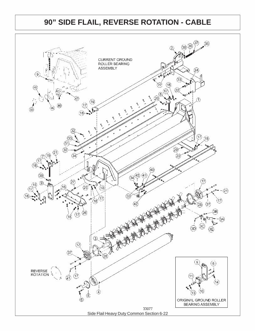
Side Flail Heavy Duty Common Section 6-22
90” SIDE FLAIL, REVERSE ROTATION - CABLE

Side Flail Heavy Duty Common Section 6-23
90” SIDE FLAIL, REVERSE ROTATION - CABLE
ITEM P/N QTY DESCRIPTION
1 27047 1 BONNET,90,HD,TSF2 27048A 1 MOUNTING FRAME3 TF1102A 1 CUTTERSHAFT,ASSY,90" HD,STC3A 33714 80 KNIFE,FLAIL,STANDARD3B 21677 40 NYLOCK NUT,7/16” NC3C TF1020 40 KNIFE MTG CLEVIS,FLAIL3D 34011 40 KNIFE MTG BOLT,FLAIL3E TF1019F 40 KNIFE,FLAIL (SMOOTH CUT)4 27972A 1 GROUND ROLLER5 TF1045B 2 GRND ROLLER STUB SHAFT6 6T2330 12 CAPSCREW, 7/16 x 1 1/2, SOCKET HEAD7 TF4334 1 ROD,GROUND ROLLER ADJ,RT8 TF4335 1 ROD,GROUND ROLLER ADJ,LF9 TF4333A 2 GROUND ROLLER ADJ BRK10 TF1022S 2 BEARING,FLANGE,1-3/8"11 30565 2 BEARING CAP KEEPER12 TF1018 2 BEARING,FLANGE,2-3/16"13 24701 4 HEX NUT, 7/16" NC (STOVER NUT)14 6T2331 4 CAPSCREW, 7/16 x 1, SOCKET HEAD15 TF4336 4 CLAMPING BLOCK, LH16 6T2291 8 PLOW BOLT,1/2" X 2" NC17 21990 31 LOCKWASHER, 1/2"18 21725 23 HEX NUT, 1/2" NC19 21731 6 CAPSCREW, 1/2 X 1 1/2,NC20 21732 3 CAPSCREW, 1/2 x 1 3/4,NC21 21733 9 CAPSCREW, 1/2 x 2,NC22 21783 5 CAPSCREW, 5/8 x 2,NC23 21992 5 LOCKWASHER, 5/824 21775 5 HEX NUT, 5/825 TF1040 1 GUARD, CUTTER SHAFT26 TF4371 1 SKID SHOE,L/PROFILE - OUTER27 21730 5 CAPSCREW, 1/2 X 1 1/4,NC28 31204 2 STRING GUARD, HD29 TF4365 1 SKID SHOE,L/PROFILE - INNER30 TF1116 1 FLAP,DEFLECTOR,TSF/TRF 9031 TF1135 1 FLAP RETAINING BAR32 21632 13 CAPSCREW,3/8" X 1-1/2" NC33 22016 23 FLATWASHER,3/8"34 21625 18 HEX NUT,3/8",NC35 21745 1 CAPSCREW, 1/2 x 7,NC36 27005 1 SPRING, PUSHOFF, SIDE RTRY37 27938 9 BUSHING,MACH,1ODx1/2IDx14GA.38 21727 1 NYLOCK NUT, 1/239 21399 2 HEX NUT, 3/4" (ACME THRD)40 TF1503 1 FRONT TRASH GUARD41 21358 1 BAR, TRASH GUARD42 21630 5 CAPSCREW, 3/8 x 1,NC43 21988 5 LOCKWASHER, 3/8"46 06520028 2 BEARING,FLANGE, 1 3/8”47 6T2331 8 CAPSCREW, 7/16” X 1”, SOCKET HEAD48 06520027 2 CAP,BEARING, GRND ROLLER49 06520029 2 O-RING,2 3/4" X 3/32”50 06530001 12 CAPSCREW, SKT HD
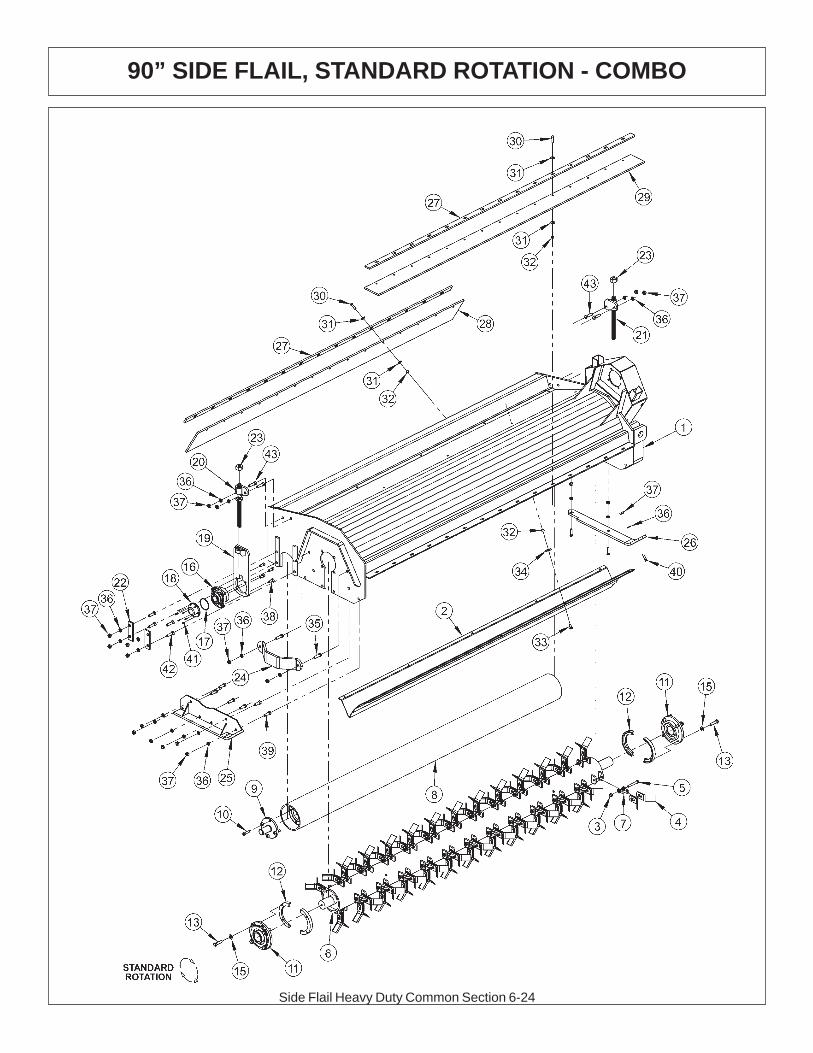
Side Flail Heavy Duty Common Section 6-24
90” SIDE FLAIL, STANDARD ROTATION - COMBO

Side Flail Heavy Duty Common Section 6-25
90” SIDE FLAIL, STANDARD ROTATION - COMBO
ITEM P/N QTY DESCRIPTION
1 22083A 1 BONNET,90,HD,T3F,RT2 TF1502A 1 BAFFLE,FLAIL,90HD,STD ROT
TF1102A 1 CUTSHFT ASSY,90HD,STD KNIVES3 21677 48 NYLOCK NUT,7/16 NC4 33714 96 KNIFE,FLAIL,STANDARD5 34011 48 CAPSCREW,7/16x3 7/16,NC GR86 TF1102 1 CUTTERSHAFT,90,HD7 TF1020 48 KNIFE MTG CLEVIS,FLAIL8 27972A 1 GROUND ROLLER,909 TF1045B 2 STUB SHAFT,GROUND ROLLER10 6T2330 8 CAPSCREW,SKT HD,7/16X1-1/2NC11 TF1018 2 BEARING,FLANGE,2-3/16
06200347 * STRING GUARD,KIT,HD(ITEMS 12,13,15)12 31204 2 STRING GUARD, HD13 06530217 8 CAPSCREW,1/2 X 2,NC,L915 06533006 12 FLATWASHER,1/2,SAE,L916 06520028 2 BEARING,FLANGE,1 3/8,GRNDRLR17 06520029 2 O-RING,2 3/4x3/32,AS568A-14818 06520027 2 CAP,BEARING,GRNDRLR19 TF4333A 2 GROUND ROLLER ADJ,BRKT20 TF4334 1 ROD,GROUND ROLLER ADJ,RT21 TF4335 1 ROD,GROUND ROLLER ADJ,LF22 TF4336 4 PLATE,GROUND ROLLER LOCK23 21399 2 HEX NUT,3/4 (ACME) BULK24 TF1040 1 GUARD,CUTTER SHAFT25 TF4371 1 SKID SHOE,L/PROFILE-OUTER26 23272A 1 SKID SHOE,T3F,INNER27 TF1135 2 BAR,FLAP,TSF/TRF 9028 TF1116 1 FLAP,DEFLECTOR,TSF/TRF 9029 06520243 1 FLAP,90",FRONT30 21632 30 CAPSCREW,3/8 X 1-1/2 NC31 22016 60 FLATWASHER,3/832 21625 40 HEX NUT,3/8 NC33 6T2283 10 CARRIAGE BOLT,3/8 X 1 NC34 6T2615 10 WASHER,FENDER 3/835 21732 2 CAPSCREW,1/2 X 1-3/4 NC36 21990 23 LOCKWASHER,1/237 21725 23 HEX NUT,1/2 NC38 6T2331 8 CAPSCREW,SKT HD,7/16 X 1 NC39 21730 6 CAPSCREW,1/2 X 1-1/4 NC40 23293 3 PLOW,BOLT,1/2 X 1-3/4 NC41 06530001 12 CAPSCREW,SKT HD,8-32x1/2,SS42 6T2291 8 PLOW BOLT,1/2 X 2 NC GR543 21731 4 CAPSCREW,1/2 X 1-1/2 NC
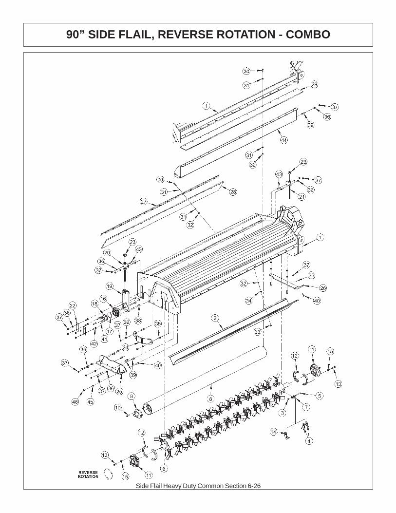
Side Flail Heavy Duty Common Section 6-26
90” SIDE FLAIL, REVERSE ROTATION - COMBO

Side Flail Heavy Duty Common Section 6-27
90” SIDE FLAIL, REVERSE ROTATION - COMBO
ITEM P/N QTY DESCRIPTION
1 22083A 1 BONNET,90,HD,T3F,RT1 22084A 1 BONNET 90” T3F2 TF1502A 1 BAFFLE,FLAIL,90HD (STANDARD ROTATION ONLY)
TF1102A 1 CUTSHFT ASSY,90HD,STD KNIVES3 21677 48 NYLOCK NUT,7/16 NC4 33714 96 KNIFE,FLAIL,STANDARD5 34011 48 CAPSCREW,7/16x3 7/16,NC GR86 TF1102 1 CUTTERSHAFT,90,HD7 TF1020 48 KNIFE MTG CLEVIS,FLAIL8 27972A 1 GROUND ROLLER,909 TF1045B 2 STUB SHAFT,GROUND ROLLER10 6T2330 8 CAPSCREW,SKT HD,7/16X1-1/2NC11 TF1018 2 BEARING,FLANGE,2-3/16
06200347 * STRING GUARD,KIT,HD(ITEMS 12,13,15)12 31204 2 STRING GUARD, HD13 06530217 8 CAPSCREW,1/2 X 2,NC,L914 TF1019F 48 KNIFE,FLAIL (SMOOTH CUT)15 06533006 12 FLATWASHER,1/2,SAE,L916 06520028 2 BEARING,FLANGE,1 3/8,GRNDRLR17 06520029 2 O-RING,2 3/4x3/32,AS568A-14818 06520027 2 CAP,BEARING,GRNDRLR19 TF4333A 2 GROUND ROLLER ADJ,BRKT20 TF4334 1 ROD,GROUND ROLLER ADJ,RT21 TF4335 1 ROD,GROUND ROLLER ADJ,LF22 TF4336 4 PLATE,GROUND ROLLER LOCK23 21399 2 HEX NUT,3/4 (ACME) BULK24 TF1040 1 GUARD,CUTTER SHAFT25 TF4371 1 SKID SHOE,L/PROFILE-OUTER26 23272A 1 SKID SHOE,T3F,INNER27 TF1135 1 BAR,FLAP,TSF/TRF 9028 TF1116 1 FLAP,DEFLECTOR,TSF/TRF 9029 06520243 1 FLAP,90",FRONT30 21632 30 CAPSCREW,3/8 X 1-1/2 NC31 22016 60 FLATWASHER,3/832 21625 40 HEX NUT,3/8 NC33 6T2283 10 CARRIAGE BOLT,3/8 X 1 NC34 6T2615 10 WASHER,FENDER 3/835 21732 2 CAPSCREW,1/2 X 1-3/4 NC36 21990 23 LOCKWASHER,1/237 21725 23 HEX NUT,1/2 NC38 6T2331 8 CAPSCREW,SKT HD,7/16 X 1 NC39 21730 6 CAPSCREW,1/2 X 1-1/4 NC40 23293 3 PLOW,BOLT,1/2 X 1-3/4 NC41 06530001 12 CAPSCREW,SKT HD,8-32x1/2,SS42 6T2291 8 PLOW BOLT,1/2 X 2 NC GR543 21731 4 CAPSCREW,1/2 X 1-1/2 NC44 TF1503 1 TRASH GUARD,90REV ROT-HD45 22018 1 FLATWASHER,1/2,WIDE46 21727 1 NYLOCK NUT,1/2 NC
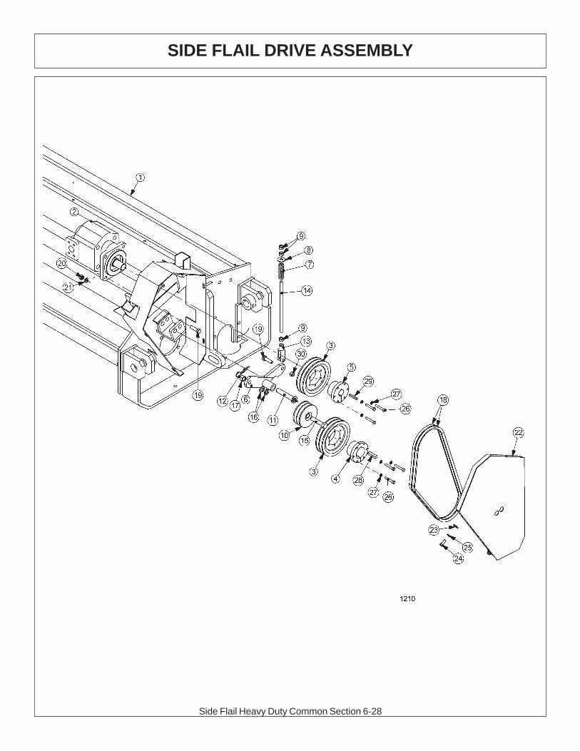
Side Flail Heavy Duty Common Section 6-28
SIDE FLAIL DRIVE ASSEMBLY

Side Flail Heavy Duty Common Section 6-29
ITEM P/N QTY DESCRIPTION
1 * REF BONNET - REFER TO FLAIL PARTS2 06504013 1 CURRENT MOTOR,TSF
23174 1 ORIGINAL MOTOR,TSF2 TF4400 1 MOTOR, T3F3 TF3040 2 SHEAVE,6.34 TF3011 1 BUSHING,QD,SK,2-3/16"5 TF3013 1 BUSHING,QD,SK 1-1/4"6 TF4345 OPT. IDLER ARM (REVERSE ROTATION - NOT SHOWN)
6 TF4346 1 IDLER ARM (STANDARD ROTATION)7 TF3620A 1 SPRING,TENSIONER8 22018 1 FLATWASHER,1/2",WIDE9 21700 3 HEX NUT, 1/2", NF10 31293 1 SHEAVE,IDLER ASSY, 4.4 O.D.11 TF3605 1 PIN,IDLER ARM 3/4"X4-1/4"12 6T3004 1 R-CLIP (HAIRPIN COTTER, 3/16")13 PT3611A 1 CLEVIS,6"14 32494 1 ROD, THREADED, 1/2-20NF15 21787 1 CAPSCREW,5/8" x 3", NC16 21992 2 LOCKWASHER, 5/817 21775 1 HEX NUT, 5/818 TF3020 2 V-BELT, (530)19 21732 5 CAPSCREW, 1/2 x 1 3/4,NC20 21725 4 HEX NUT, 1/2" NC21 21990 4 LOCKWASHER, 1/2"22 TF4564 1 BELT SHEILD (RIGHT)22 TF4565 1 BELT SHEILD (LEFT)23 22016 4 FLATWASHER,3/8"24 21630 4 CAPSCREW, 3/8 x 1,NC25 21988 4 LOCKWASHER, 3/8"26 21584 6 CAPSCREW, 5/16 x 2,NC27 21987 6 LOCKWASHER, 5/16"28 TF1025 1 KEY,1/4" X 1/2" X 1-7/8" SQ29 TF1125 1 KEY,3/8" X 1/2" X 1-7/8" SQ30 21727 1 NYLOCK NUT, 1/2
SIDE FLAIL DRIVE ASSEMBLY
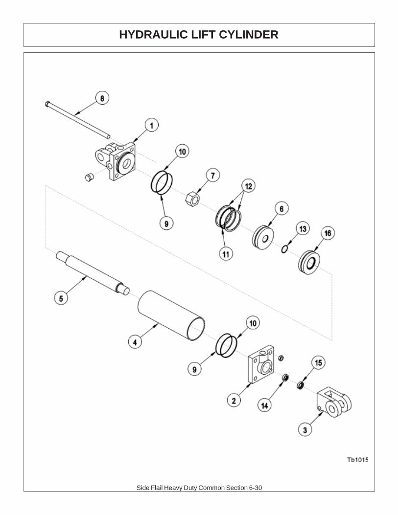
Side Flail Heavy Duty Common Section 6-30
HYDRAULIC LIFT CYLINDER

Side Flail Heavy Duty Common Section 6-31
HYDRAULIC LIFT CYLINDER
3” X 10” CYLINDER #6T0151R
ITEM PART NO. QTY. DESCRIPTION1 6T0167 1 CYLINDER BUTT2 6T0170 1 CYLINDER GLAND3 6T0178 1 CLEVIS END4 6T0164 1 CYLINDER TUBE5 6T0161 1 PISTON ROD6 6T0173 1 PISTON7 6T0179 1 LOCKNUT8 6T0176 4 TIE ROD ASY
6T0187 AVAIL SEAL KIT9 2 O - RING10 2 BACK - UP WASHER11 1 O - RING12 2 BACK - UP WASHER13 1 O - RING14 1 U - CUP15 1 WIPER16 NA NA
3” X 11.5” CYLINDER #25343
ITEM PART NO. QTY. DESCRIPTION1 6T0167 1 CYLINDER BUTT2 6T0170 1 CYLINDER GLAND3 6T0178 1 CLEVIS END4 6T0204 1 CYLINDER TUBE5 6T0203 1 PISTON ROD6 6T0173 1 PISTON7 6T0179 1 LOCKNUT8 6T0205 1 TIE ROD ASY
6T0187 AVAIL SEAL KIT9 2 O - RING10 2 BACK - UP WASHER11 1 O - RING12 2 BACK - UP WASHER13 1 O - RING14 1 U - CUP15 1 WIPER16 6T0206 1 SPACER
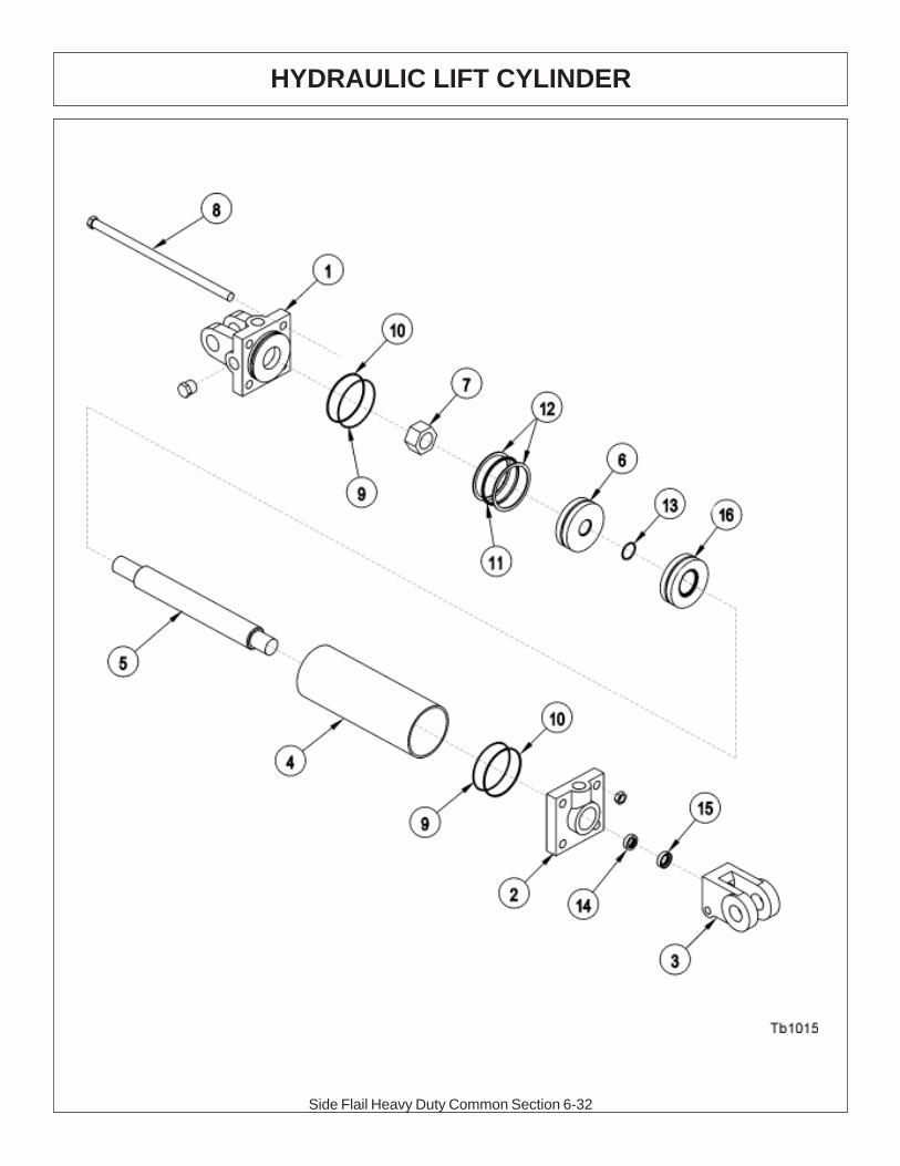
Side Flail Heavy Duty Common Section 6-32
HYDRAULIC LIFT CYLINDER

Side Flail Heavy Duty Common Section 6-33
HYDRAULIC LIFT CYLINDER
3” X 12” CYLINDER # 32215
ITEM PART NO. QTY. DESCRIPTION
1 6T0167 1 CYLINDER BUTT2 6T0170 1 CYLINDER GLAND3 6T0178 1 CLEVIS END4 6T0204 1 CYLINDER TUBE5 6T0203 1 PISTON ROD6 6T0173 1 PISTON7 6T0179 1 LOCKNUT8 6T0205 1 TIE ROD ASY
6T0187 AVAIL SEAL KIT9 2 O - RING10 2 BACK - UP WASHER11 1 O - RING12 2 BACK - UP WASHER13 1 O - RING14 1 U - CUP15 1 WIPER
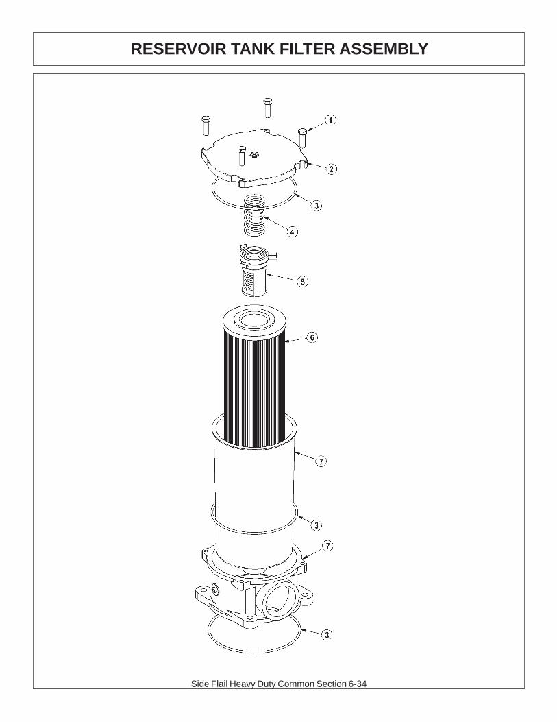
Side Flail Heavy Duty Common Section 6-34
RESERVOIR TANK FILTER ASSEMBLY

Side Flail Heavy Duty Common Section 6-35
RESERVOIR TANK FILTER ASSEMBLY
ITEM PART NO. QTY. DESCRIPTION
06505044 AVAIL FILTER ASSY SAE 10 MICRON1 28583 4 CAPSCREW,8MMX25MM(1.25 PITCH)2 06505045 1 COVER3 06505046 1 SEAL KIT4 06505047 1 SPRING5 06505048 1 BYPASS6 35259 1 FILTER,10 MIC,RETURN LINE7 06505049 1 CAN/BODY

Side Flail Heavy Duty Common Section 6-36
2SP HUSCO - LOAD SENSE (06502040)
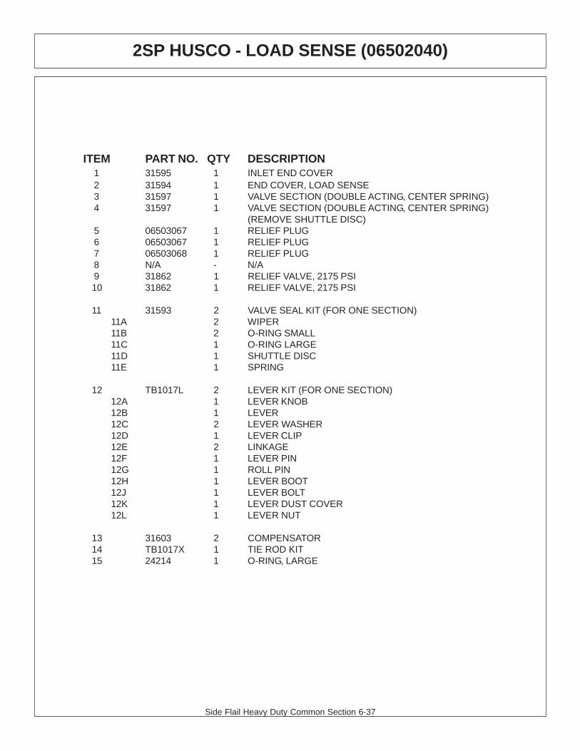
Side Flail Heavy Duty Common Section 6-37
2SP HUSCO - LOAD SENSE (06502040)
ITEM PART NO. QTY DESCRIPTION1 31595 1 INLET END COVER2 31594 1 END COVER, LOAD SENSE3 31597 1 VALVE SECTION (DOUBLE ACTING, CENTER SPRING)4 31597 1 VALVE SECTION (DOUBLE ACTING, CENTER SPRING)
(REMOVE SHUTTLE DISC)5 06503067 1 RELIEF PLUG6 06503067 1 RELIEF PLUG7 06503068 1 RELIEF PLUG8 N/A - N/A9 31862 1 RELIEF VALVE, 2175 PSI10 31862 1 RELIEF VALVE, 2175 PSI
11 31593 2 VALVE SEAL KIT (FOR ONE SECTION)11A 2 WIPER11B 2 O-RING SMALL11C 1 O-RING LARGE11D 1 SHUTTLE DISC11E 1 SPRING
12 TB1017L 2 LEVER KIT (FOR ONE SECTION)12A 1 LEVER KNOB12B 1 LEVER12C 2 LEVER WASHER12D 1 LEVER CLIP12E 2 LINKAGE12F 1 LEVER PIN12G 1 ROLL PIN12H 1 LEVER BOOT12J 1 LEVER BOLT12K 1 LEVER DUST COVER12L 1 LEVER NUT
13 31603 2 COMPENSATOR14 TB1017X 1 TIE ROD KIT15 24214 1 O-RING, LARGE

Side Flail Heavy Duty Common Section 6-38
2SP HUSCO - LOAD SENSE (06502042)

Side Flail Heavy Duty Common Section 6-39
2SP HUSCO - LOAD SENSE (06502042)
ITEM PART NO. QTY DESCRIPTION1 31595 1 INLET END COVER2 31594 1 END COVER, LOAD SENSE3 31600 1 VALVE SECTION (DOUBLE ACTING, DETENT FLOAT)4 31600 1 VALVE SECTION (DOUBLE ACTING, DETENT FLOAT)
(REMOVE SHUTTLE DISC)5 06503067 1 RELIEF PLUG6 31861 1 RELIEF VALVE 360 PSI7 06503068 1 RELIEF PLUG8 6T4209 1 RELIEF PLUG9 31862 1 RELIEF VALVE, 2175 PSI10 31862 1 RELIEF VALVE, 2175 PSI
11 31593 2 VALVE SEAL KIT (FOR ONE SECTION)11A 2 WIPER11B 2 O-RING SMALL11C 1 O-RING LARGE11D 1 SHUTTLE DISC11E 1 SPRING
12 TB1017L 2 LEVER KIT (FOR ONE SECTION)12A 1 LEVER KNOB12B 1 LEVER12C 2 LEVER WASHER12D 1 LEVER CLIP12E 2 LINKAGE12F 1 LEVER PIN12G 1 ROLL PIN12H 1 LEVER BOOT12J 1 LEVER BOLT12K 1 LEVER DUST COVER12L 1 LEVER NUT
13 31603 2 COMPENSATOR14 TB1017X 1 TIE ROD KIT15 24214 1 O-RING, LARGE

Side Flail Heavy Duty Common Section 6-40
2SP HUSCO - LOAD SENSE (31320)

Side Flail Heavy Duty Common Section 6-41
2SP HUSCO - LOAD SENSE (31320)
ITEM PART NO. QTY DESCRIPTION1 31595 1 INLET END COVER2 31594 1 END COVER, LOAD SENSE3 31597 1 VALVE SECTION (DOUBLE ACTING, CENTER SPRING)4 31597 1 VALVE SECTION (DOUBLE ACTING, CENTER SPRING)5 06503067 1 RELIEF PLUG6 06503067 1 RELIEF PLUG7 N/A - N/A8 6T4209 1 RELIEF PLUG9 31862 1 RELIEF VALVE, 2175 PSI10 31862 1 RELIEF VALVE, 2175 PSI
11 31593 2 VALVE SEAL KIT (FOR ONE SECTION)11A 2 WIPER11B 2 O-RING SMALL11C 1 O-RING LARGE11D 1 SHUTTLE DISC11E 1 SPRING
12 TB1017L 2 LEVER KIT (FOR ONE SECTION)12A 1 LEVER KNOB12B 1 LEVER12C 2 LEVER WASHER12D 1 LEVER CLIP12E 2 LINKAGE12F 1 LEVER PIN12G 1 ROLL PIN12H 1 LEVER BOOT12J 1 LEVER BOLT12K 1 LEVER DUST COVER12L 1 LEVER NUT
13 31603 2 COMPENSATOR14 TB1017X 1 TIE ROD KIT15 24214 1 O-RING, LARGE
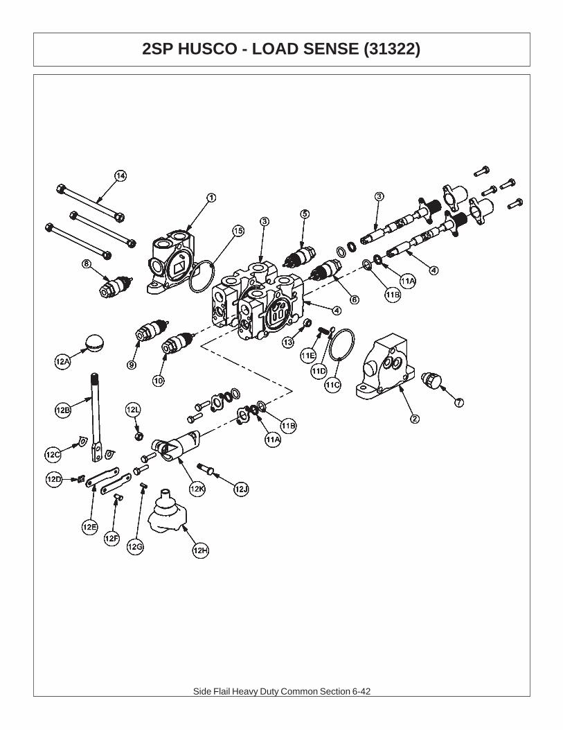
Side Flail Heavy Duty Common Section 6-42
2SP HUSCO - LOAD SENSE (31322)

Side Flail Heavy Duty Common Section 6-43
2SP HUSCO - LOAD SENSE (31322)
ITEM PART NO. QTY DESCRIPTION1 31595 1 INLET END COVER2 31594 1 END COVER, LOAD SENSE3 31600 1 VALVE SECTION (DOUBLE ACTING, DETENT - FLOAT)4 31600 1 VALVE SECTION (DOUBLE ACTING, DETENT - FLOAT)5 06503067 1 RELIEF PLUG6 31861 1 RELIEF VALVE, 360 PSI7 N/A - N/A8 6T4209 1 RELIEF PLUG9 31862 1 RELIEF VALVE, 2175 PSI10 31862 1 RELIEF VALVE, 2175 PSI
11 31593 2 VALVE SEAL KIT (FOR ONE SECTION)11A 2 WIPER11B 2 O-RING SMALL11C 1 O-RING LARGE11D 1 SHUTTLE DISC11E 1 SPRING
12 TB1017L 2 LEVER KIT (FOR ONE SECTION)12A 1 LEVER KNOB12B 1 LEVER12C 2 LEVER WASHER12D 1 LEVER CLIP12E 2 LINKAGE12F 1 LEVER PIN12G 1 ROLL PIN12H 1 LEVER BOOT12J 1 LEVER BOLT12K 1 LEVER DUST COVER12L 1 LEVER NUT
13 31603 2 COMPENSATOR14 TB1017X 1 TIE ROD KIT15 24214 1 O-RING, LARGE
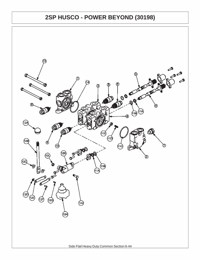
Side Flail Heavy Duty Common Section 6-44
2SP HUSCO - POWER BEYOND (30198)

Side Flail Heavy Duty Common Section 6-45
2SP HUSCO - POWER BEYOND (30198)
ITEM PART NO. QTY DESCRIPTION1 TB1017S 1 INLET END COVER2 TB1702 1 END COVER, POWER BEYOND3 TF3009 1 VALVE SECTION (DOUBLE ACTING, DETENT - FLOAT)4 TF3009 1 VALVE SECTION (DOUBLE ACTING, DETENT - FLOAT)5 06503067 1 RELIEF PLUG6 TF4212 1 RELIEF VALVE, 200 PSI7 TB1017M 1 SHUT-OFF PLUG8 TB1017E 1 RELIEF VALVE, 2250 PSI9 TB1017M 1 SHUT-OFF PLUG10 TB1017M 1 SHUT-OFF PLUG
11 TB1017A 2 VALVE SEAL KIT (FOR ONE SECTION)11A 2 WIPER11B 2 O-RING SMALL11C 1 O-RING LARGE11D 1 SPRING11E 1 PUCKET
12 TB1017L 2 LEVER KIT (FOR ONE SECTION)12A 1 LEVER KNOB12B 1 LEVER12C 2 LEVER WASHER12D 1 LEVER CLIP12E 2 LINKAGE12F 1 LEVER PIN12G 1 ROLL PIN12H 1 LEVER BOOT12J 1 LEVER BOLT12K 1 LEVER DUST COVER12L 1 LEVER NUT
13 TB1017X 1 TIE ROD KIT14 24214 1 O-RING, LARGE

Side Flail Heavy Duty Common Section 6-46
2SP HUSCO - POWER BEYOND (30801)

Side Flail Heavy Duty Common Section 6-47
2SP HUSCO - POWER BEYOND (30801)
ITEM PART NO. QTY DESCRIPTION1 TB1017S 1 INLET END COVER2 TB1702 1 END COVER, POWER BEYOND3 TB1017P 1 VALVE SECTION (SINGLE ACTING, SPRING DETENT)4 06502091 1 VALVE SECTION (DOUBLE ACTING, CENTER SPRING)
(NO AUX VALVE PORTS)5 N/A - N/A6 N/A - N/A7 TB1017M 1 SHUT-OFF PLUG8 TB1017E 1 RELIEF VALVE, 2250 PSI9 TB1017M 1 SHUT-OFF PLUG10 N/A - N/A
11 TB1017A 2 VALVE SEAL KIT (FOR ONE SECTION)11A 2 WIPER11B 2 O-RING SMALL11C 1 O-RING LARGE11D 1 SPRING11E 1 PUCKET
12 TB1017L 2 LEVER KIT (FOR ONE SECTION)12A 1 LEVER KNOB12B 1 LEVER12C 2 LEVER WASHER12D 1 LEVER CLIP12E 2 LINKAGE12F 1 LEVER PIN12G 1 ROLL PIN12H 1 LEVER BOOT12J 1 LEVER BOLT12K 1 LEVER DUST COVER12L 1 LEVER NUT
13 TB1017X 1 TIE ROD KIT14 24214 1 O-RING, LARGE
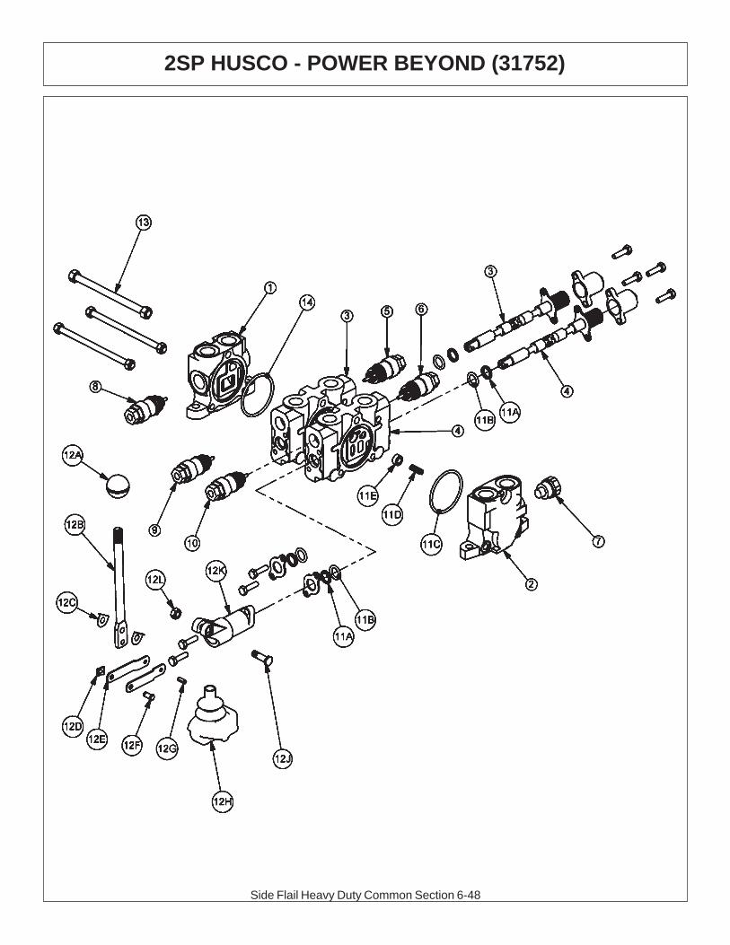
Side Flail Heavy Duty Common Section 6-48
2SP HUSCO - POWER BEYOND (31752)

Side Flail Heavy Duty Common Section 6-49
2SP HUSCO - POWER BEYOND (31752)
ITEM PART NO. QTY DESCRIPTION1 TB1017S 1 INLET END COVER2 TB1702 1 END COVER, POWER BEYOND3 TB1017P 1 VALVE SECTION (SINGLE ACTING, SPRING DETENT)4 TB1017P 1 VALVE SECTION (SINGLE ACTING, SPRING DETENT)5 N/A - N/A6 N/A - N/A7 TB1017M 1 SHUT-OFF PLUG8 TB1017E 1 RELIEF VALVE, 2250 PSI9 TB1017M 1 SHUT-OFF PLUG10 TB1017M 1 TB1017M
11 TB1017A 2 VALVE SEAL KIT (FOR ONE SECTION)11A 2 WIPER11B 2 O-RING SMALL11C 1 O-RING LARGE11D 1 SPRING11E 1 PUCKET
12 TB1017L 2 LEVER KIT (FOR ONE SECTION)12A 1 LEVER KNOB12B 1 LEVER12C 2 LEVER WASHER12D 1 LEVER CLIP12E 2 LINKAGE12F 1 LEVER PIN12G 1 ROLL PIN12H 1 LEVER BOOT12J 1 LEVER BOLT12K 1 LEVER DUST COVER12L 1 LEVER NUT
13 TB1017X 1 TIE ROD KIT14 24214 1 O-RING, LARGE
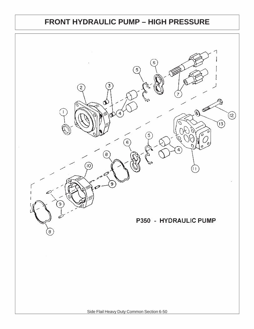
Side Flail Heavy Duty Common Section 6-50
FRONT HYDRAULIC PUMP – HIGH PRESSURE

Side Flail Heavy Duty Common Section 6-51
FRONT HYDRAULIC PUMP – HIGH PRESSURE
ITEM PART NO. QTY. DESCRIPTION
* 23152 AVAIL PUMP ASSEMBLY 1 3/4” COMPLETE1 22765 1 SEAL (INCLUDED IN SEAL KIT)2 22766 1 SHAFT END COVER3 22767 2 CHECK AND END COVER4 22768 2 BUSHING5 22769 2 CHANNEL SEAL (INCLUDED IN SEAL KIT)6 22770 2 THRUST PLATE (INCLUDED IN SEAL KIT)7 22771 SET DRIVE SHAFT AND GEAR SET 1 3/4”8 22772 2 GASKET SEAL (INCLUDED IN SEAL KIT)9 22773 4 DOWEL PINS10 22774 1 GEAR HOUSING 1 3/4”11 22779 1 PORT END COVER12 23824 4 STUDS13 22781 SET WASHER
6T5322 AVAIL SEAL APPLICATOR TOOL24150 AVAIL SEAL KIT (INCLUDES 1, 5, 6 AND 8)
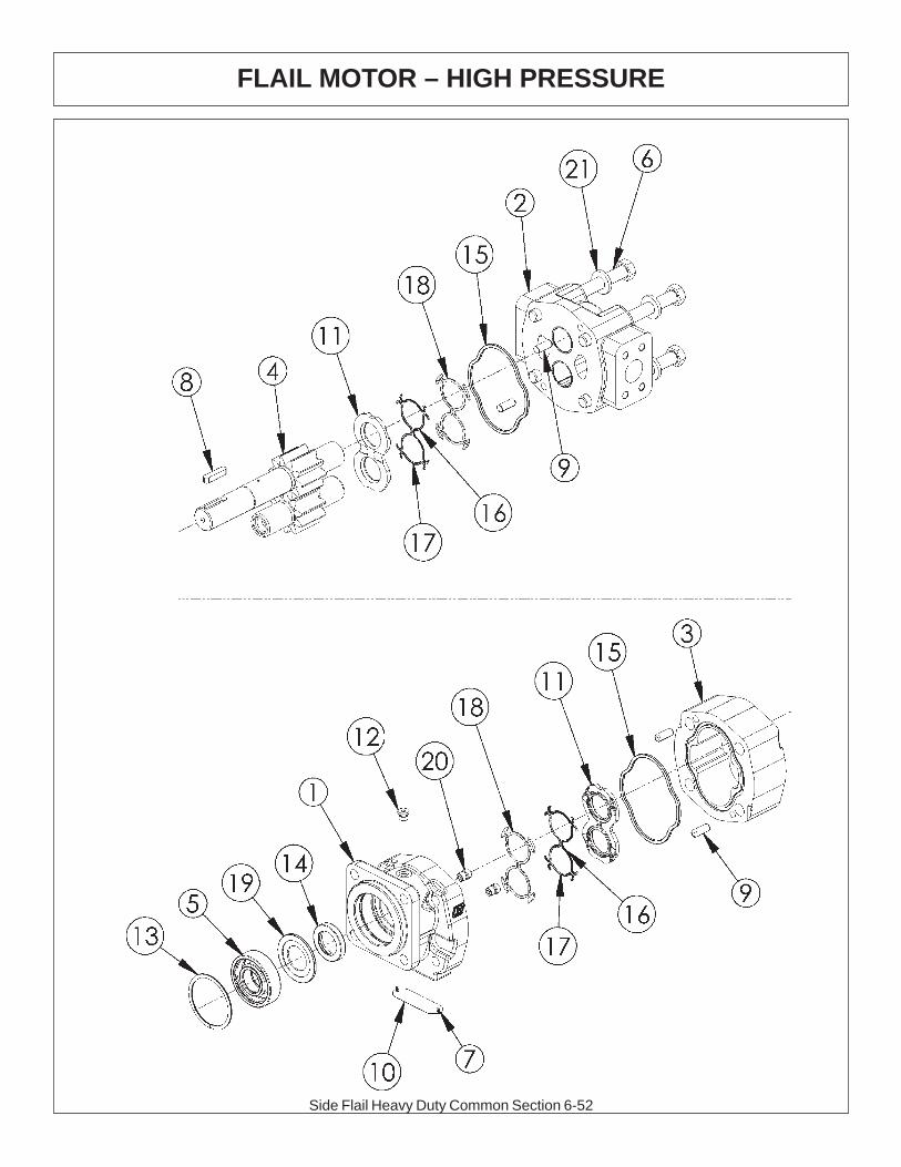
Side Flail Heavy Duty Common Section 6-52
FLAIL MOTOR – HIGH PRESSURE

Side Flail Heavy Duty Common Section 6-53
FLAIL MOTOR – HIGH PRESSURE
ITEM PART NO. QTY. DESCRIPTION
* 06504013 AVAIL MOTOR ASSEMBLY 350 - TSF1 06504039 1 SHAFT END COVER2 06504040 1 PORT END COVER3 06504041 1 GEAR HOUSING4 06504042 1 MATCHED GEAR SET5 TF4402 1 BALL BEARING6 06504043 4 CAP SCREW7 06504044 2 SET SCREW8 06504028 1 KEY9 06504045 4 DOWEL PIN10 1 NAMEPLATE11 763759 2 THRUSTPLATE12 02961940 1 HEX PLUG13 TF4401 1 SNAP RING14 06504049 1 LIP SEAL (INCLUDED IN SEAL KIT)15 TF4410 2 GASKET SEAL (INCLUDED IN SEAL KIT)16 06504046 4 SIDE SEAL (INCLUDED IN SEAL KIT)17 06504047 4 END SEAL (INCLUDED IN SEAL KIT)18 TF4407 2 BACK-UP SEAL (INCLUDED IN SEAL KIT)19 06504048 1 SEAL RETAINER20 6T5809 2 CHECK ASSEMBLY21 02961917 4 WASHER* 06504022 AVAIL SEAL KIT (INCLUDES 14, 15, 16, 17, AND 18)
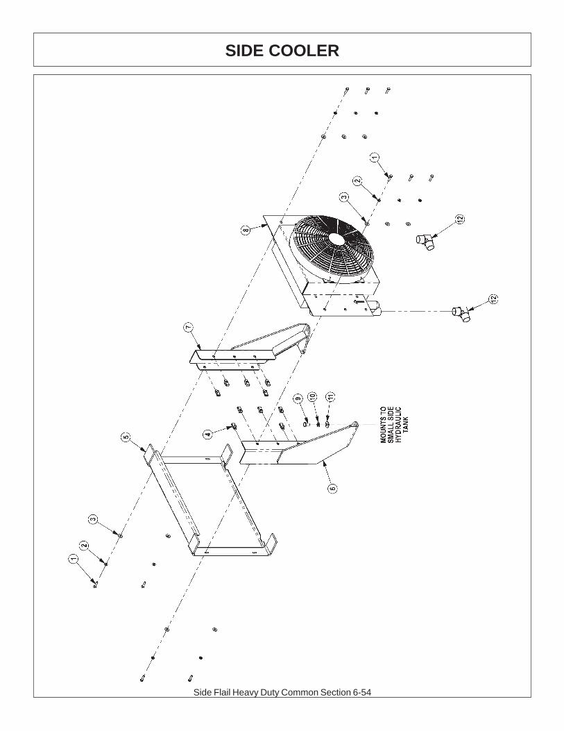
Side Flail Heavy Duty Common Section 6-54
SIDE COOLER

Side Flail Heavy Duty Common Section 6-55
SIDE COOLER
ITEM PART NO. QTY. DESCRIPTION
1 21530 10 CAPSCREW,1/4 X1 NC2 21986 10 LOCKWASHER,1/43 22014 10 FLATWASHER,1/44 35176 10 1/4 U-NUT5 06370015 1 SCREEN,COOLER,FRNT6 06380006 1 MNT,COOLER,BUMPER TANK,RH7 06380007 1 MNT,COOLER,BUMPER TANK,LH8 06510026 1 COOLER,FRONT MNT9 21629 4 CAPSCREW,3/8 X 3/4 NC10 21988 4 LOCKWASHER,3/811 22016 4 FLATWASHER,3/812 34117 2 ELBOW,1MOR X 1MJ90,FORGED
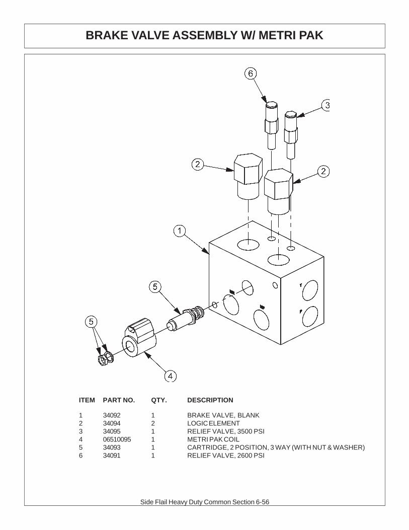
Side Flail Heavy Duty Common Section 6-56
BRAKE VALVE ASSEMBLY W/ METRI PAK
ITEM PART NO. QTY. DESCRIPTION
1 34092 1 BRAKE VALVE, BLANK2 34094 2 LOGIC ELEMENT3 34095 1 RELIEF VALVE, 3500 PSI4 06510095 1 METRI PAK COIL5 34093 1 CARTRIDGE, 2 POSITION, 3 WAY (WITH NUT & WASHER)6 34091 1 RELIEF VALVE, 2600 PSI

Side Flail Heavy Duty Common Section 6-57
SOLENOID BRAKE VALVE HYDRAULIC SCHEMATIC
BRAKE VALVE TROUBLESHOOTINGFAILURE MODE: CHECK STEPS
- MOWER WILL NOT START - system pressure is low (engine not lugging). 1 thru 6
- MOWER WILL NOT START - system pressure is high (engine lugging). “MR” port will be high pressure. 7
- MOWER WILL NOT ROTATE AT FULL SPEED - limited power. 3 thru 5
- MOWER BLADE WILL NOT STOP - blade will not stop in proper time. 7 thru 9
CORRECTIVE STEPS:
1. Check for voltage at solenoid (item 6), voltage must be between 10.2 volts and 13.8 volts.2. Remove, inspect solenoid and cartridge (items 4, 6) for wear or contamination.3. Remove, inspect logic elements near “P” port (item 3) for wear or contamination.4. Remove, inspect 3000 psi relief valve (item 2) for wear or contamination.5. Remove and inspect orifices near “P” port for contamination.6. Remove “P” port hose and fitting, visually inspect for contamination, check ball for movement.7. Remove and inspect orifices near “MR” port for contamination.8. Remove, inspect 2600 psi relief valve (item 5) for wear of contamination.9. Remove, inpect logic element near “MR” port (item 3) for wear or contamination.
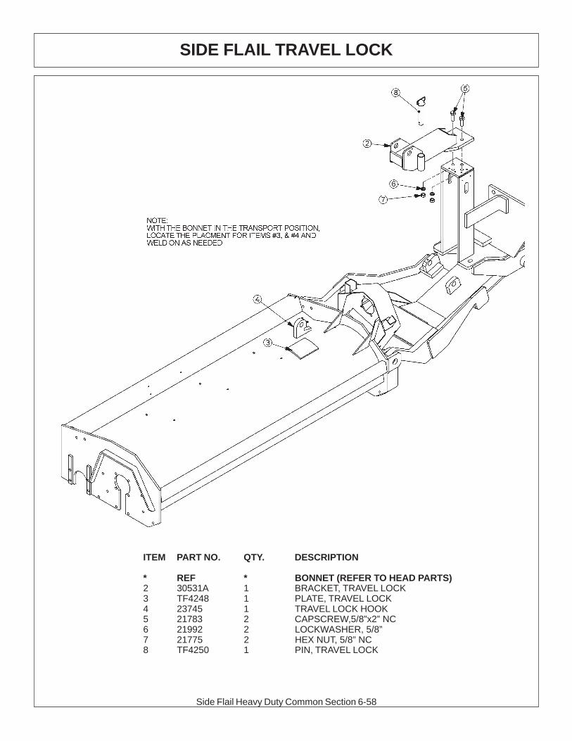
Side Flail Heavy Duty Common Section 6-58
ITEM PART NO. QTY. DESCRIPTION
* REF * BONNET (REFER TO HEAD PARTS)2 30531A 1 BRACKET, TRAVEL LOCK3 TF4248 1 PLATE, TRAVEL LOCK4 23745 1 TRAVEL LOCK HOOK5 21783 2 CAPSCREW,5/8”x2” NC6 21992 2 LOCKWASHER, 5/8”7 21775 2 HEX NUT, 5/8” NC8 TF4250 1 PIN, TRAVEL LOCK
SIDE FLAIL TRAVEL LOCK
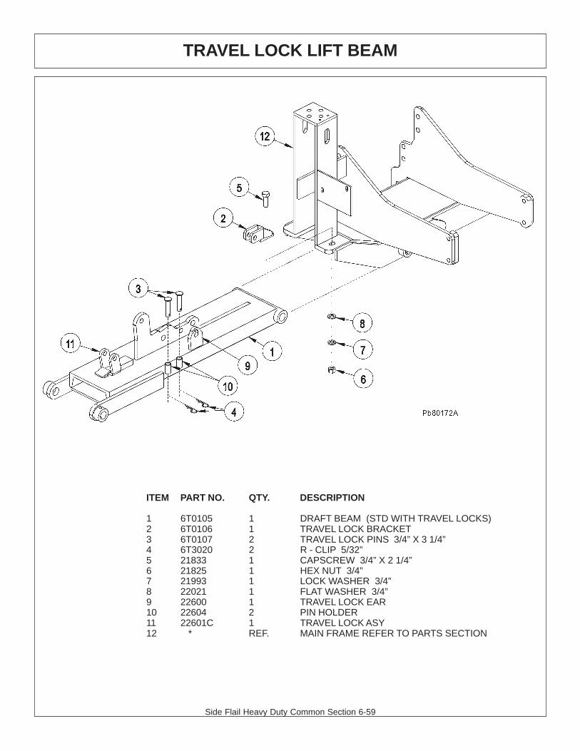
Side Flail Heavy Duty Common Section 6-59
TRAVEL LOCK LIFT BEAM
ITEM PART NO. QTY. DESCRIPTION
1 6T0105 1 DRAFT BEAM (STD WITH TRAVEL LOCKS)2 6T0106 1 TRAVEL LOCK BRACKET3 6T0107 2 TRAVEL LOCK PINS 3/4” X 3 1/4”4 6T3020 2 R - CLIP 5/32”5 21833 1 CAPSCREW 3/4” X 2 1/4”6 21825 1 HEX NUT 3/4”7 21993 1 LOCK WASHER 3/4”8 22021 1 FLAT WASHER 3/4”9 22600 1 TRAVEL LOCK EAR10 22604 2 PIN HOLDER11 22601C 1 TRAVEL LOCK ASY12 * REF. MAIN FRAME REFER TO PARTS SECTION

Side Flail Heavy Duty Common Section 6-60
SWITCHBOX SERVICE PARTS
ITEM P/N QTY. DESCRIPTION 1 06514013 1 SWBX,ALUM,BLK,06510102 2 35226 1 SWITCH,MOWER,COLEHERSEE 3 33811 1 SWITCH,MASTER/DECK FLOAT 4 6T3923 1 INDICTATOR LIGHT,ON,RED 5 06514014 1 BREAKER,10A,SWBX 6 34540 1 STRAIN RELIEF,3/4,BLACK,NYLON 7 06550018 1 DECAL,SWTCHBX,TM/TSF,CG 8 35227 1 RELAY,DP,DT,12V,LY2F,35226
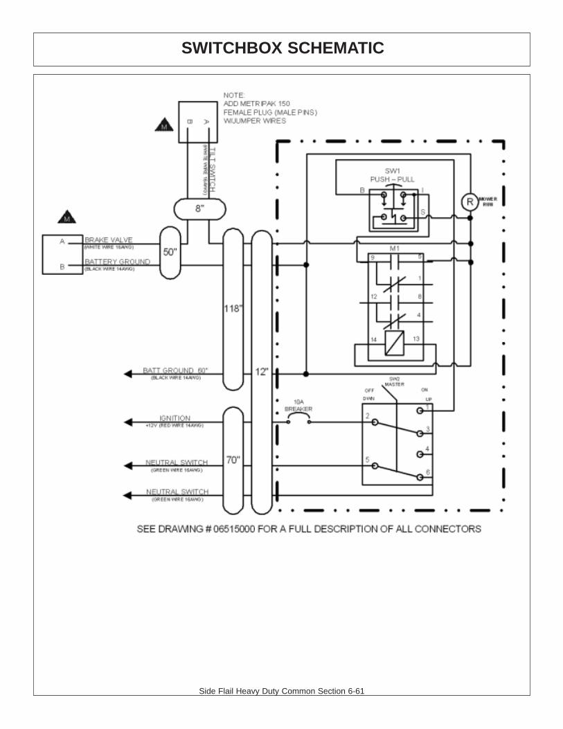
Side Flail Heavy Duty Common Section 6-61
SWITCHBOX SCHEMATIC

Side Flail Heavy Duty Common Section 6-62

WARRANTYSECTION
Warranty Section 7-1

.

WARRANTY INFORMATION
Tiger Corporation, 3301 N. Louise, Sioux Falls, South Dakota, warrants to theoriginal Retail Customer, the new Tiger equipment is free of defects in material andworkmanship. Any part of equipment that in Tiger’s judgement, show evidence ofsuch defects will be repaired or replaced without charge, provided that the failure ofpart(s) shall have occurred within twelve (12) months from the date of delivery ofsaid equipment to the Retail Customer. Expendable components such as knives,oil, chain sprockets, skid shoes, knife mounting disks and the like are excluded butnot limited to this warranty.
The Retail Customer must pay the transportation cost to and from the TigerDealer’s service shop for warranty service. Warranty service will be performed bythe Tiger Dealer from whom the equipment was purchased, during service shopregularly scheduled days and hours of operation.
All Tiger obligation under this warranty shall be terminated if the equipment ismodified or altered in ways not approved in writing by Tiger, if repair parts other thangenuine Tiger repair parts have been used, or if the equipment has been subject tomisuse, neglect, accident, improper maintenance or improper operation.
Tiger Corporation reserves the right to make improvements in design orchanges in specification at any time without incurring any obligation to owners ofequipment previously sold.
No agent or person has authority to alter, add to or waive the above warrantieswhich are agreed to be in the only warranties, representations or promises,expressed or implied, as to the quality or performance of the products covered andwhich do not include any implied warranty of merchantability or fitness. In no eventwill Tiger be liable for incidental or consequential damages or injuries, including, butnot limited to, loss of profits, rental or substitute equipment or other commercialloss.
THERE ARE NO WARRANTIES WHICH EXTENDBEYOND THOSE EXPRESSED HEREIN.
It is the Purchasers obligation to sign the warranty registration form AFTER he /she has Read and Understands the Operation and Safety Instructions statedwithin this manual.

ONE LAST WORDThis manual cannot possibly cover all of the
potentially hazardous situations you willencounter. By being familiar with the
safety rules, operating and maintenanceinstructions in this manual you can help preventaccidents. The objective of this manual is to
help make you a better operator. Remember,SAFETY IS YOU!
Your safety and the safety of those around youdepends on YOU. Common sense should
play a large role in the operation of this machine.
Since we at Tiger Corporation are constantly striving to improve out products, wereserve the right to change specifications or design at any time.

TO THE OWNER / OPERATOR / DEALER
To keep your implement running efficiently and safely, read your manual thoroughly and followthese directions and the Safety Messages in this manual and on the machine. The table ofcontents clearly identifies each section where you can easily find the information you need.
The Occupational Safety and Health Act (OSHA 1928.51 subpart C) makes the followingminimum requirements for tractor operators.
OWNER REQUIREMENTS:
1. Provide a Roll-Over-Protective Structure that meets the requirements of this Standard; and2. Provide Seatbelts that meet the requirements of this Standard and SAE J3C; and3. Ensure that each employee uses such Seatbelt while the tractor is moving; and4. Ensure that each employee tightens the Seatbelt sufficiently to confine the employee to the pro-
tected area provided by the ROPS.
OPERATOR REQUIREMENTS:
1. Securely fasten seatbelt it the tractor has a ROPS.2. Where possible, avoid operating the tractor near steep ditches, embankments, and holes.3. Reduce speed when turning, crossing slopes, and on rough, slick, or muddy surfaces.4. Stay off slopes too steep for safe operation.5. Watch where you are going – especially at row ends, on roads, and around trees.6. Do Not permit others to ride.7. Operate the tractor smoothly – no jerky turns, starts, or stops.8. Hitch only to the draw-bar and hitch points recommended by the tractor manufacturer.9. When the tractor is stopped, set brakes securely and use park lock, if available

Printed in USA© Tiger Corporation