Embed Size (px)
Citation preview
Side-of-Pole Mount for 2 Modules (SPM2)For Module Type D
step-by-step
assembly and installation
ASSEMBLY INSTRUCTIONS
Version 1, Rev ASP3352-2 PCN 042712-1
A few words about the product
For foundation and pipe size recommendations on a specific installation, please contact us at:
Phone: 800-260-3792
Email: [email protected]
About these Assembly Instructions
These instructions...
Ÿ Are intended to be used by individuals with sufficient technical skills for the task. Knowledge and use of hand tools, measuring devices and torque values is also required.
Ÿ Include various precautions in the forms of Notes, Cautions, and Warnings. These are to assist in the assembly process and/or to draw attention to the fact that certain assembly steps may be dangerous and could cause serious personal injury and/or damage to components. Following the step-by-step procedures and these precautions should minimize the risk of any personal injury or damage to components while making the installation not only safe but an efficient process.
Required Tools
The SPM2 for module type D is designed to mount on 3 - 4.5 O.D. pipe (installer supplied). Options are available for mounting to larger diameter poles.
Pipe size and foundation requirements are based on several factors including the array surface area, maximum design wind speed, exposure category, soil type, steepest expected tilt angle, and above-ground clearance.
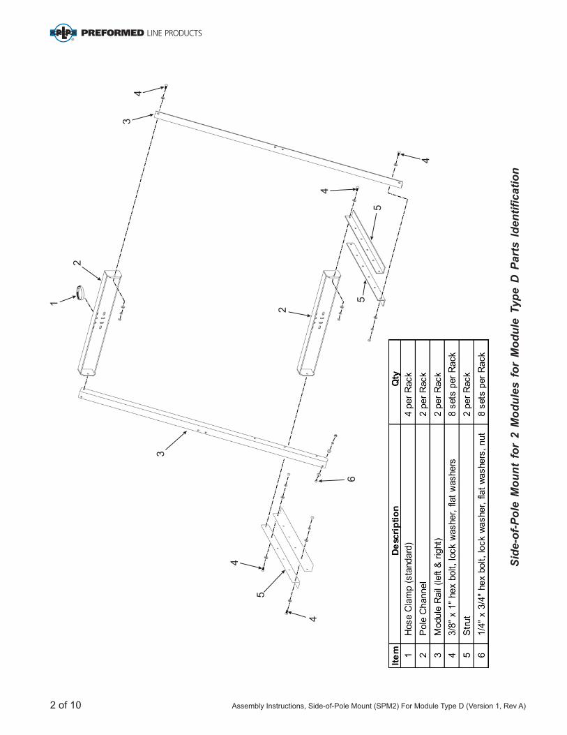
7/16 inch wrench or socket for 1/4 inch module hardware
9/16 inch wrench or socket for 3/8 inch hardware
Torque wrench
Ratchet wrench
Ratchet extension bar
˝ ˝
Side-of-Pole Mount for 2 Module (SPM2) For Module Type D
WARNING:Follow the procedures and precautions in these instructions carefully.
Assembly Instructions, Side-of-Pole Mount (SPM2) For Module Type D (Version 1, Rev A) 1 of 10
1
2
2
3
3
4
4
6
5
5
5
4
44
Sid
e-o
f-P
ole
Mo
un
t fo
r 2 M
od
ule
s f
or
Mo
du
le T
yp
e D
Part
s I
den
tifi
cati
on
2 of 10 Assembly Instructions, Side-of-Pole Mount (SPM2) For Module Type D (Version 1, Rev A)
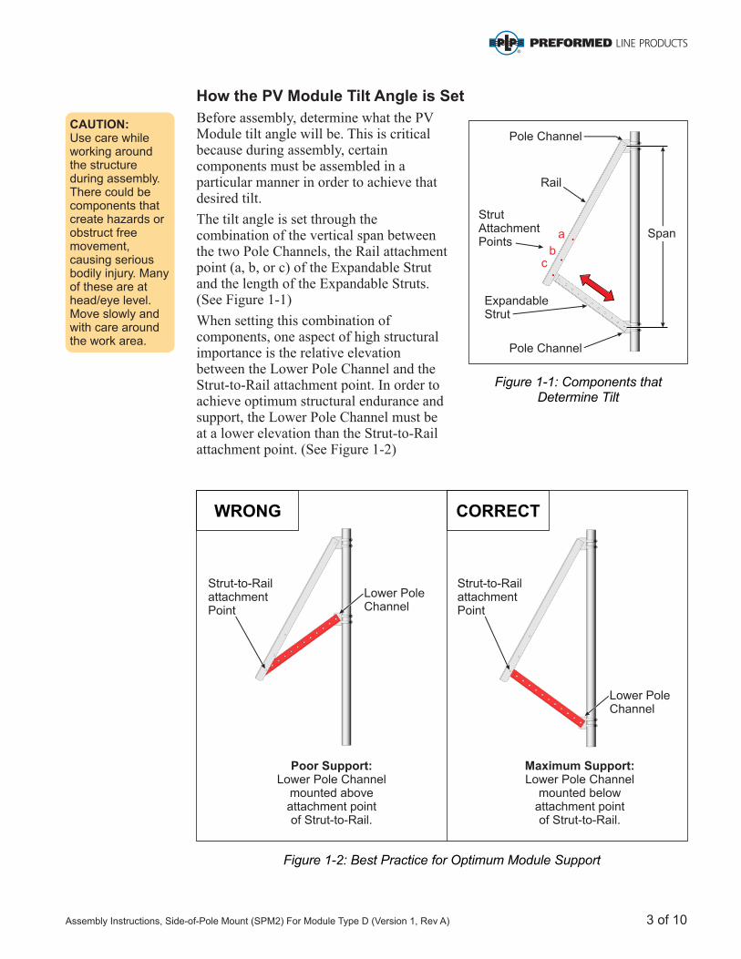
How the PV Module Tilt Angle is Set
Before assembly, determine what the PV Module tilt angle will be. This is critical because during assembly, certain components must be assembled in a particular manner in order to achieve that desired tilt.
The tilt angle is set through the combination of the vertical span between the two Pole Channels, the Rail attachment point (a, b, or c) of the Expandable Strut and the length of the Expandable Struts. (See Figure 1-1)
When setting this combination of components, one aspect of high structural importance is the relative elevation between the Lower Pole Channel and the Strut-to-Rail attachment point. In order to achieve optimum structural endurance and support, the Lower Pole Channel must be at a lower elevation than the Strut-to-Rail attachment point. (See Figure 1-2)
CAUTION:Use care while working around the structure during assembly. There could be components that create hazards or obstruct free movement, causing serious bodily injury. Many of these are at head/eye level. Move slowly and with care around the work area.
Figure 1-1: Components that Determine Tilt
Figure 1-2: Best Practice for Optimum Module Support
StrutAttachmentPoints
Rail
Pole Channel
Pole Channel
ExpandableStrut
a
bc
Span
Poor Support:Lower Pole Channel
mounted above attachment pointof Strut-to-Rail.
Strut-to-RailattachmentPoint
Strut-to-RailattachmentPoint
Lower PoleChannel
Lower PoleChannel
WRONG
Maximum Support:Lower Pole Channel
mounted below attachment pointof Strut-to-Rail.
CORRECT
Assembly Instructions, Side-of-Pole Mount (SPM2) For Module Type D (Version 1, Rev A) 3 of 10
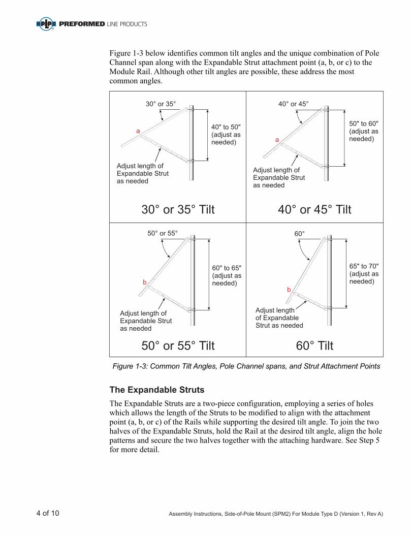
Figure 1-3 below identifies common tilt angles and the unique combination of Pole Channel span along with the Expandable Strut attachment point (a, b, or c) to the Module Rail. Although other tilt angles are possible, these address the most common angles.
The Expandable Struts
The Expandable Struts are a two-piece configuration, employing a series of holes which allows the length of the Struts to be modified to align with the attachment point (a, b, or c) of the Rails while supporting the desired tilt angle. To join the two halves of the Expandable Struts, hold the Rail at the desired tilt angle, align the hole patterns and secure the two halves together with the attaching hardware. See Step 5 for more detail.
Figure 1-3: Common Tilt Angles, Pole Channel spans, and Strut Attachment Points
30 or ° 35° Tilt
30 or 35° °
a40" to 50"(adjust asneeded)
Adjust length ofExpandable Strut as needed
b
50° or 55° Tilt
50 ° or 55°
60" to 65"(adjust asneeded)
Adjust length ofExpandable Strut as needed
b
60° Tilt
60°
65" to 70"(adjust as needed)
Adjust length of Expandable Strut as needed
Adjust length ofExpandable Strut as needed
40° or 45° Tilt
40 ° or 45°
50" to 60"(adjust asneeded)a
4 of 10 Assembly Instructions, Side-of-Pole Mount (SPM2) For Module Type D (Version 1, Rev A)
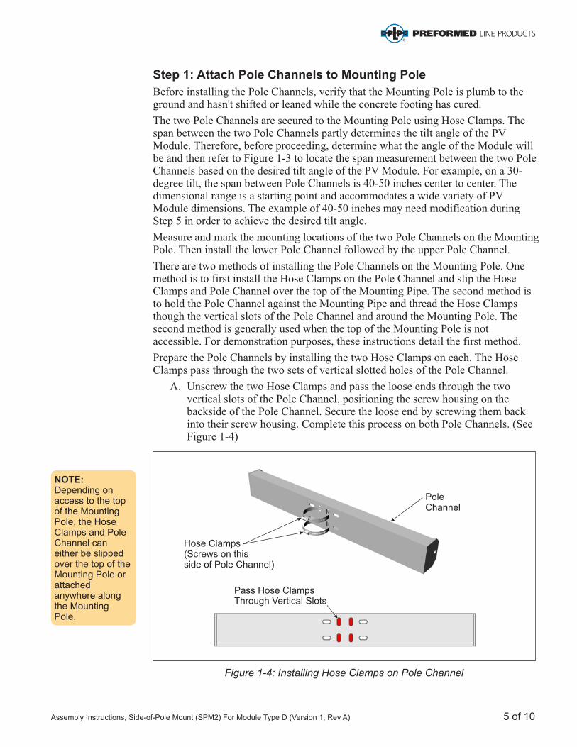
Hose Clamps(Screws on this side of Pole Channel)
PoleChannel
Pass Hose ClampsThrough Vertical Slots
Step 1: Attach Pole Channels to Mounting Pole
Before installing the Pole Channels, verify that the Mounting Pole is plumb to the ground and hasn't shifted or leaned while the concrete footing has cured.
The two Pole Channels are secured to the Mounting Pole using Hose Clamps. The span between the two Pole Channels partly determines the tilt angle of the PV Module. Therefore, before proceeding, determine what the angle of the Module will be and then refer to Figure 1-3 to locate the span measurement between the two Pole Channels based on the desired tilt angle of the PV Module. For example, on a 30-degree tilt, the span between Pole Channels is 40-50 inches center to center. The dimensional range is a starting point and accommodates a wide variety of PV Module dimensions. The example of 40-50 inches may need modification during Step 5 in order to achieve the desired tilt angle.
Measure and mark the mounting locations of the two Pole Channels on the Mounting Pole. Then install the lower Pole Channel followed by the upper Pole Channel.
There are two methods of installing the Pole Channels on the Mounting Pole. One method is to first install the Hose Clamps on the Pole Channel and slip the Hose Clamps and Pole Channel over the top of the Mounting Pipe. The second method is to hold the Pole Channel against the Mounting Pipe and thread the Hose Clamps though the vertical slots of the Pole Channel and around the Mounting Pole. The second method is generally used when the top of the Mounting Pole is not accessible. For demonstration purposes, these instructions detail the first method.
Prepare the Pole Channels by installing the two Hose Clamps on each. The Hose Clamps pass through the two sets of vertical slotted holes of the Pole Channel.
A. Unscrew the two Hose Clamps and pass the loose ends through the two vertical slots of the Pole Channel, positioning the screw housing on the backside of the Pole Channel. Secure the loose end by screwing them back into their screw housing. Complete this process on both Pole Channels. (See Figure 1-4)
Figure 1-4: Installing Hose Clamps on Pole Channel
NOTE:Depending on access to the top of the Mounting Pole, the Hose Clamps and Pole Channel can either be slipped over the top of the Mounting Pole or attached anywhere along the Mounting Pole.
Assembly Instructions, Side-of-Pole Mount (SPM2) For Module Type D (Version 1, Rev A) 5 of 10
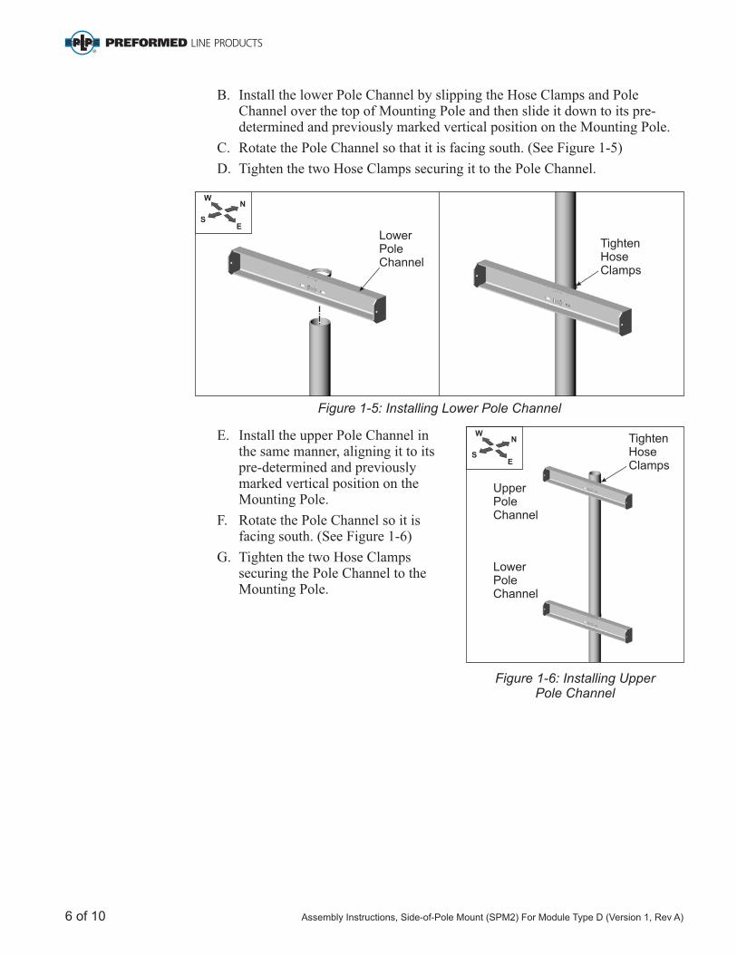
E. Install the upper Pole Channel in the same manner, aligning it to its pre-determined and previously marked vertical position on the Mounting Pole.
F. Rotate the Pole Channel so it is facing south. (See Figure 1-6)
G. Tighten the two Hose Clamps securing the Pole Channel to the Mounting Pole.
Figure 1-6: Installing Upper Pole Channel
Figure 1-5: Installing Lower Pole Channel
B. Install the lower Pole Channel by slipping the Hose Clamps and Pole Channel over the top of Mounting Pole and then slide it down to its pre-determined and previously marked vertical position on the Mounting Pole.
C. Rotate the Pole Channel so that it is facing south. (See Figure 1-5)
D. Tighten the two Hose Clamps securing it to the Pole Channel.
N
E
W
S
TightenHoseClamps
LowerPole Channel
UpperPole Channel
LowerPole Channel
TightenHose Clamps
N
E
W
S
6 of 10 Assembly Instructions, Side-of-Pole Mount (SPM2) For Module Type D (Version 1, Rev A)

Figure 2-1: Attaching First Half of Expandable Struts to Pole Channel
Step 2: Attaching First Half of Expandable Struts to Lower Pole Channel
The Expandable Struts are attached to the ends of the lower Pole Channel using 3/8 x 1 hex bolts and hardware. The Struts are attached/assembled in two stages with one half installed here (See Figure 2-1) and second half installed in Step 4.
A. Orient and align the Struts as shown in Figure 2-1. Secure with one 3/8 x 1 hex bolt, lock washer, flat washers, and Hex Nut, and finger tighten for now.
"
" "
"
Figure 3-1: Attaching Rails to Pole Channel
Step 3: Attaching Module Rails to Upper Pole Channel
The two Module Rails are attached to the ends of the upper Pole Channel using 3/8 x 1 hex bolts and hardware. (See Figure 3-1)
A. Orient and align the left Module Rail as shown in Figure 3-1. Secure with one 3/8 x 1 hex bolt, lock washer, flat washers, and Hex Nut. Finger tighten for now.
B. Continue in this manner to install the right Module Rail, and finger tighten for now.
""
" "
3/8Hex Nut
"
3/8 x 1Hex Bolt
" "
Expandable Strut (one of two parts)
Expandable Strut (one of two parts)
LockWasher
FlatWashers
Lower Pole Channel
3/8Hex Nut
"
3/8 x 1Hex Bolt
" "
Rail (Right)
Rail (Left)
LockWasher
FlatWashers
Upper Pole Channel
Assembly Instructions, Side-of-Pole Mount (SPM2) For Module Type D (Version 1, Rev A) 7 of 10
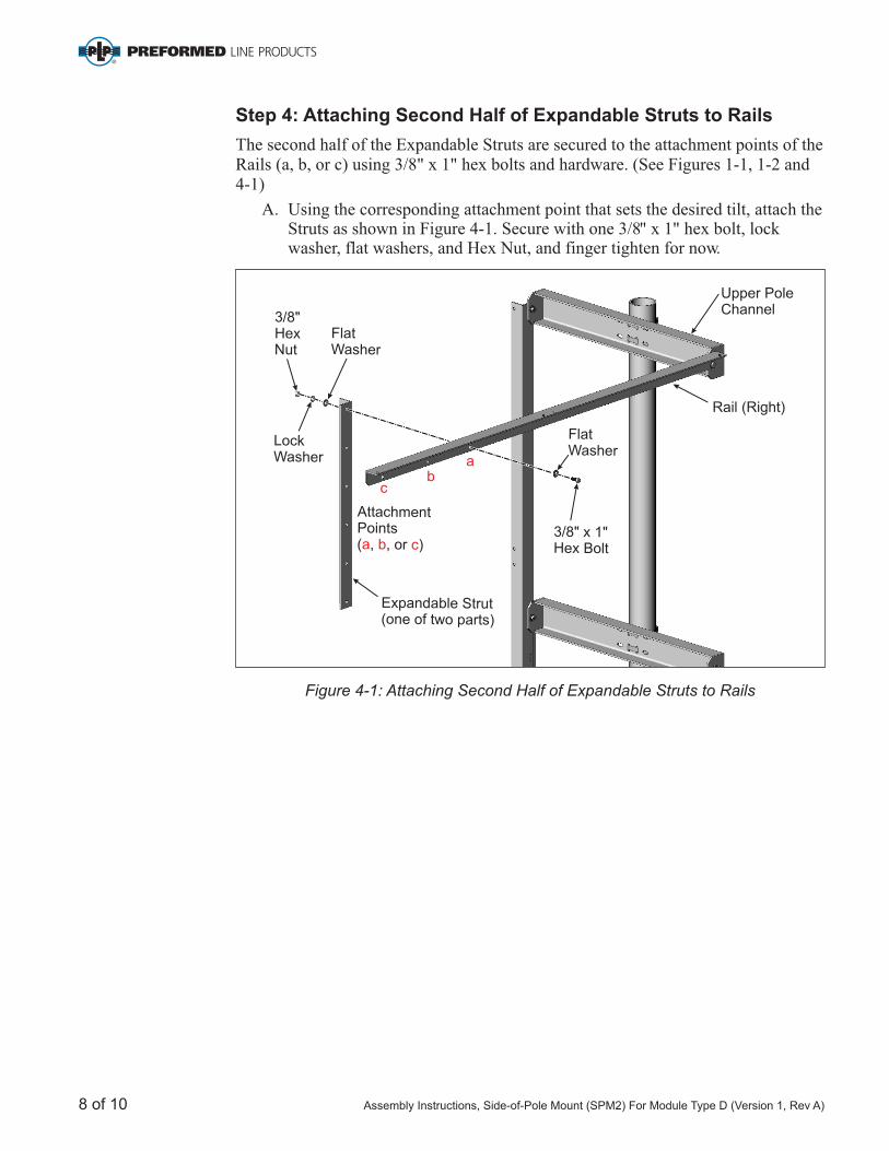
Step 4: Attaching Second Half of Expandable Struts to Rails
The second half of the Expandable Struts are secured to the attachment points of the Rails (a, b, or c) using 3/8 x 1 hex bolts and hardware. (See Figures 1-1, 1-2 and 4-1)
A. Using the corresponding attachment point that sets the desired tilt, attach the Struts as shown in Figure 4-1. Secure with one 3/8 x 1 hex bolt, lock washer, flat washers, and Hex Nut, and finger tighten for now.
" "
" "
Figure 4-1: Attaching Second Half of Expandable Struts to Rails
Rail (Right)
Upper Pole Channel
3/8Hex Nut
"
3/8 x 1Hex Bolt
" "
LockWasher
Expandable Strut (one of two parts)
FlatWasher
FlatWasher
ab
c
AttachmentPoints ( , , or )a b c
8 of 10 Assembly Instructions, Side-of-Pole Mount (SPM2) For Module Type D (Version 1, Rev A)

Figure 5-1: Joining the Two Halves of the Expandable Struts
Step 5: Joining the Two Halves of the Expandable Strut
The two halves of the Expandable Struts are secured to one another using 3/8 x 1 hex bolts and hardware. To join
(using a device like an inclinometer)
C. Secure the two halves with 3/8 x 1 bolt, lock washer, flat washers, and hex nut. Be sure and insert the bolts in the last hole on each of the two halves as shown in Figure 5-1. Torque to 32-34 ft.-lbs.
D. Continue in this manner and join the two halves of the other Expandable Strut.
" "
" " hex
the two halves of the Expandable Struts, hold the Rail at the desired tilt angle , align the hole patterns and secure the two halves together with the attaching hardware.
A. Rotate and hold the Module Rail at the desired tilt angle.
B. Rotate the two halves of the Expandable Strut, bringing their hole patterns into alignment with one another. If their hole patterns do not line up, it may be necessary to loosen the Lower Pole Channel and raise or lower it along the mounting pole.
3/8Hex Nut
"
3/8 x 1Hex Bolt
" "
Insert bolts in the last open hole of each strut
Module Rail (Right)
Inclinometer
LockWasher
FlatWashers
WARNING: Both bolts must be used for the rack to be stable.
Assembly Instructions, Side-of-Pole Mount (SPM2) For Module Type D (Version 1, Rev A) 9 of 10

= Torque to32-34 ft.-lbs.
These two bolts must be in the last open hole of each strut.
Step 7: Attach PV Module to Module Rails
PV Modules are secured to the Module Rails using 1/4 x 3/4 bolts and hardware. In general there are four attachment points per Module.
A. Place the Module on the Module Rails. While one person holds the Module in place, align the mounting holes and secure with four 1/4 x 3/4 bolts and hardware. Torque to 6-8 ft.-lbs. (See Figure 7-1)
B. Continue in this manner and install the second Module.
" "
" "
Figure 7-1: Attaching Module to Rail
CAUTION:This is a two person activity. The PV Module is heavy and unstable before fully secured to the Module Rails. The PV Module must be held in place by one person while the second person aligns and secures it to the Module Rails. Failure to do so could lead to serious personal injury and damaged components.
Module
Lock WasherFlat Washer
1/4 Nut"
1/4 x 3/4 Boltand Flat Washer
" "
Strut
Rail
Step 6: Return and Tighten Hardware
Return and tighten the hardware securing the Module Rails and Struts to the upper and lower Pole Channels. Torque to 32-34 ft.-lbs. (See Figure 6-1)
Figure 6-1: Return and Tighten Hardware
CAUTION:Be certain to return and tighten all hardware, securing the Rails and Struts to the Upper and Lower Pole Channels.
10 of 10 Assembly Instructions, Side-of-Pole Mount (SPM2) For Module Type D (Version 1, Rev A)

Corporate Headquarters660 Beta DriveMayfield Village, OH 44143
Albuquerque Office1700 Louisiana Blvd., Suite 130Albuquerque, NM 87110
Telephone: 800.260.3792Fax: 505.889.3548www.preformed.comE-mail: [email protected]
© 2017 Preformed Line ProductsPCN 042712-4 Version 1, Rev ASP3352-2