Embed Size (px)
Citation preview

NANO EXPRESS Open Access
Side Flow Effect on Surface Generation inNano CuttingFeifei Xu1,2, Fengzhou Fang1,3* and Xiaodong Zhang1
Abstract
The side flow of material in nano cutting is one of the most important factors that deteriorate the machinedsurface quality. The effects of the crystallographic orientation, feed, and the cutting tool geometry, including tooledge radius, rake angle and inclination angle, on the side flow are investigated employing molecular dynamicssimulation. The results show that the stagnation region is formed in front of tool edge and it is characterized bythe stagnation radius Rs and stagnation height hs. The side flow is formed because the material at or under thestagnation region is extruded by the tool edge to flow to the side of the tool edge. Higher stagnation heightwould increase the size of the side flow. The anisotropic nature of the material which partly determines thestagnation region also influences the side flow due to the different deformation mechanism under the action ofthe tool edge. At different cutting directions, the size of the side flow has a great difference which would finallyaffect the machined surface quality. The cutting directions of {100} < 011>, {110} < 001>, and {110} < 1-10 >are beneficial to obtain a better surface quality with small side flow. Besides that, the side flow could besuppressed by reducing the feed and optimizing the cutting tool geometry. Cutting tool with small edgeradius, large positive rake angle, and inclination angle would decrease the side flow and consequentlyimprove the machined surface quality.
Keywords: Nano cutting, Side flow, Surface generation, Plastic deformation, Cutting mechanism
BackgroundUltra-precision cutting is one of the most commonmethods in realizing the nanometric surface rough-ness and sub-micrometric form accuracy. Based onthe assumption that the workpiece material is re-moved ideally and the machined surface texture isthe replication of tool nose profile, the surfaceroughness could attain nanometric even sub-nanometric scale, if simply decreasing the feed andincreasing the tool nose radius. However, it alwaysdeviates from its ideal value due to many factors,such as, material properties of workpiece [1–4] andcutting tool geometry [5–7]. The side flow of work-piece material, which is a result of the interactionsbetween cutting tool and workpiece material, is
considered to be an important role in causing thedeviation [8]. It is the plastic deformation of work-piece material at a direction opposite to the feeddirection [9]. Two mechanisms are proposed to de-scribe the formation of material side flow [7]. Thefirst one is the squeeze between the tool flank faceand the machined surface especially when the uncutchip thickness (UCT) is less than the minimum un-cut chip thickness. The second one is due to thetrailing edge notch. The material is pressed asideunder high temperature and pressure. Material sideflow has been modeled by 3D thermo elasto-viscoplastic finite element method and found thatmore side flow is generated with higher nose radiusand lower feed [10]. The side flow of material hasbeen taken into account to predict the machinedsurface roughness [8, 11].In nano cutting, the ever-reduced UCT making the
material removal at nanoscale which is smaller thanthe material grain size causing the significant influ-ence of the size effects [12] and material removal
* Correspondence: [email protected] Key Laboratory of Precision Measuring Technology and Instruments,Centre of MicroNano Manufacturing Technology, Tianjin University, Tianjin300072, China3School of Mechanical and Materials Engineering, MNMT-Dublin, UniversityCollege Dublin, Dublin, IrelandFull list of author information is available at the end of the article
© The Author(s). 2017 Open Access This article is distributed under the terms of the Creative Commons Attribution 4.0International License (http://creativecommons.org/licenses/by/4.0/), which permits unrestricted use, distribution, andreproduction in any medium, provided you give appropriate credit to the original author(s) and the source, provide a link tothe Creative Commons license, and indicate if changes were made.
Xu et al. Nanoscale Research Letters (2017) 12:359 DOI 10.1186/s11671-017-2136-3
mechanism [13–15]. The anisotropic nature of singlecrystal materials would appear in the nano cutting,even the machined materials are polycrystalline [16].Lee et al. investigated the anisotropy of surfaceroughness on three different crystal planes in cuttingprocess [3]. The difference of machined surfaceroughness is explained by the different amount ofrecovery induced by the anisotropic Yong’s modulus.To et al. found that {100} plane of single crystalaluminum could attain a best machined surfaceroughness [2]. The anisotropy of single crystal 3C-SiC during nano-cutting has also been found byGoel et al. using molecular dynamics (MD) simula-tion [1]. However, the influence of anisotropic natureof single crystal material on side flow has not beendeeply investigated by far, which plays an importantrole in determining the machined surface quality.Besides that, when the UCT is comparable to the
cutting tool edge radius, the effect of tool edge onmachined surface quality could no longer beneglected. For instance, the increased tool edge ra-dius would increase the surface roughness [17], andthe spring back of the machined material affected bythe cutting tool edge is thought to be responsible ofthe machined surface roughness [18]. At the tooledge, there is a region or point where the materialtends to separate [19, 20]. The point is thought to bethe stagnation point [14, 15, 21], and the region isthe stagnation region where the material flow velocity isalmost zero [22]. The material above the stagnation pointor region is removed to form the chip. The material belowthem is pressed down to the flank face of cutting tool toform the machined surface. The amount of pressedmaterial which is determined by the tool edge radius,is responsible of the side flow and further affects thegenerated surface quality. However, the influence ofcutting tool geometry on side flow still lacks deepinvestigations in nano-cutting.In this study, the effects of the crystallographic orien-
tation and the cutting tool geometry, including tool edgeradius, rake angle and inclination angle, on the side floware investigated employing MD simulation. This studycontributes to a better understanding of the surface gen-eration for single crystal materials and polycrystallinematerials in nano-cutting.
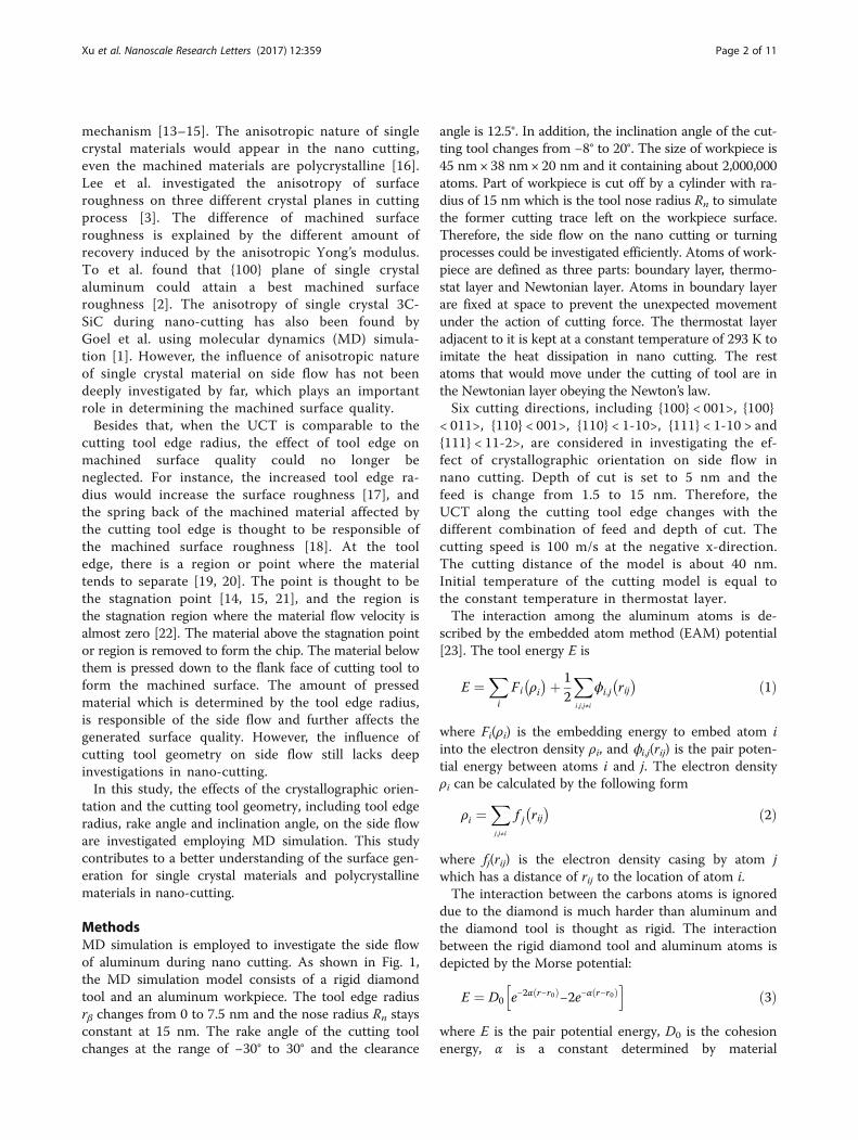
MethodsMD simulation is employed to investigate the side flowof aluminum during nano cutting. As shown in Fig. 1,the MD simulation model consists of a rigid diamondtool and an aluminum workpiece. The tool edge radiusrβ changes from 0 to 7.5 nm and the nose radius Rn staysconstant at 15 nm. The rake angle of the cutting toolchanges at the range of −30° to 30° and the clearance
angle is 12.5°. In addition, the inclination angle of the cut-ting tool changes from −8° to 20°. The size of workpiece is45 nm× 38 nm× 20 nm and it containing about 2,000,000atoms. Part of workpiece is cut off by a cylinder with ra-dius of 15 nm which is the tool nose radius Rn to simulatethe former cutting trace left on the workpiece surface.Therefore, the side flow on the nano cutting or turningprocesses could be investigated efficiently. Atoms of work-piece are defined as three parts: boundary layer, thermo-stat layer and Newtonian layer. Atoms in boundary layerare fixed at space to prevent the unexpected movementunder the action of cutting force. The thermostat layeradjacent to it is kept at a constant temperature of 293 K toimitate the heat dissipation in nano cutting. The restatoms that would move under the cutting of tool are inthe Newtonian layer obeying the Newton’s law.Six cutting directions, including {100} < 001>, {100}
< 011>, {110} < 001>, {110} < 1-10>, {111} < 1-10 > and{111} < 11-2>, are considered in investigating the ef-fect of crystallographic orientation on side flow innano cutting. Depth of cut is set to 5 nm and thefeed is change from 1.5 to 15 nm. Therefore, theUCT along the cutting tool edge changes with thedifferent combination of feed and depth of cut. Thecutting speed is 100 m/s at the negative x-direction.The cutting distance of the model is about 40 nm.Initial temperature of the cutting model is equal tothe constant temperature in thermostat layer.The interaction among the aluminum atoms is de-
scribed by the embedded atom method (EAM) potential[23]. The tool energy E is
E ¼X
i
Fi ρi� �þ 1
2
X
i;j;j≠i
ϕi;j rij� � ð1Þ
where Fi(ρi) is the embedding energy to embed atom iinto the electron density ρi, and ϕi,j(rij) is the pair poten-tial energy between atoms i and j. The electron densityρi can be calculated by the following form
ρi ¼X
j;j≠i
f j rij� � ð2Þ
where fj(rij) is the electron density casing by atom jwhich has a distance of rij to the location of atom i.The interaction between the carbons atoms is ignored
due to the diamond is much harder than aluminum andthe diamond tool is thought as rigid. The interactionbetween the rigid diamond tool and aluminum atoms isdepicted by the Morse potential:
E ¼ D0 e−2α r−r0ð Þ−2e−α r−r0ð Þh i
ð3Þ
where E is the pair potential energy, D0 is the cohesionenergy, α is a constant determined by material
Xu et al. Nanoscale Research Letters (2017) 12:359 Page 2 of 11
properties, r0 is the distance at equilibrium and r is thedistance between two atoms.The MD simulation is based on the LAMMPS and the
microstructural evolution of the workpiece undercutting process is analyzed based on common neighboranalysis with software OVITO. The displacement vectorsof the workpiece atoms are analyzed to reveal the mater-ial side flow mechanism in nano cutting.
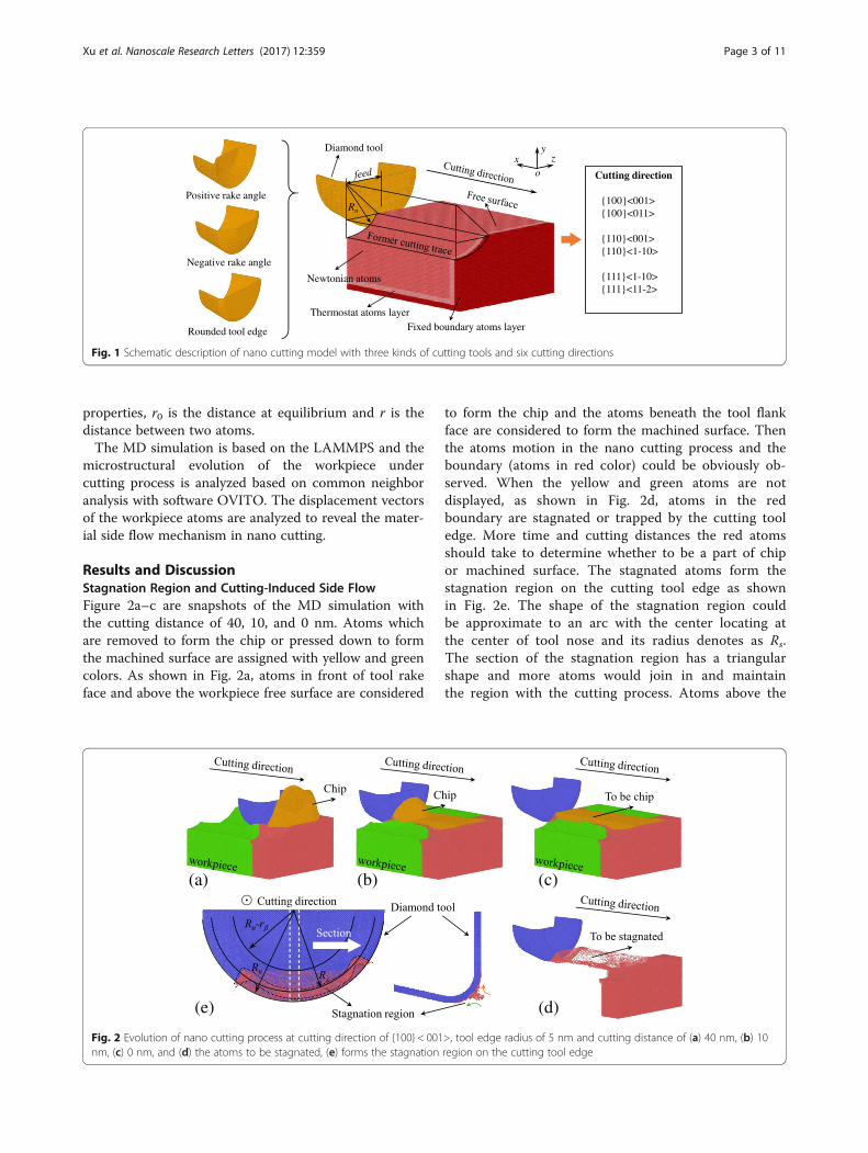
Results and DiscussionStagnation Region and Cutting-Induced Side FlowFigure 2a–c are snapshots of the MD simulation withthe cutting distance of 40, 10, and 0 nm. Atoms whichare removed to form the chip or pressed down to formthe machined surface are assigned with yellow and greencolors. As shown in Fig. 2a, atoms in front of tool rakeface and above the workpiece free surface are considered
to form the chip and the atoms beneath the tool flankface are considered to form the machined surface. Thenthe atoms motion in the nano cutting process and theboundary (atoms in red color) could be obviously ob-served. When the yellow and green atoms are notdisplayed, as shown in Fig. 2d, atoms in the redboundary are stagnated or trapped by the cutting tooledge. More time and cutting distances the red atomsshould take to determine whether to be a part of chipor machined surface. The stagnated atoms form thestagnation region on the cutting tool edge as shownin Fig. 2e. The shape of the stagnation region couldbe approximate to an arc with the center locating atthe center of tool nose and its radius denotes as Rs.The section of the stagnation region has a triangularshape and more atoms would join in and maintainthe region with the cutting process. Atoms above the
Diamond tool
Fixed boundary atoms layerThermostat atoms layer
Newtonian atoms
Rn
xyz
o
Positive rake angle
Negative rake angle
Rounded tool edge
Cutting direction
{100}<001>{100}<011>
{110}<001>{110}<1-10>
{111}<1-10>{111}<11-2>
Fig. 1 Schematic description of nano cutting model with three kinds of cutting tools and six cutting directions
(a) (b) (c)
(e) (d)
Fig. 2 Evolution of nano cutting process at cutting direction of {100} < 001>, tool edge radius of 5 nm and cutting distance of (a) 40 nm, (b) 10nm, (c) 0 nm, and (d) the atoms to be stagnated, (e) forms the stagnation region on the cutting tool edge
Xu et al. Nanoscale Research Letters (2017) 12:359 Page 3 of 11
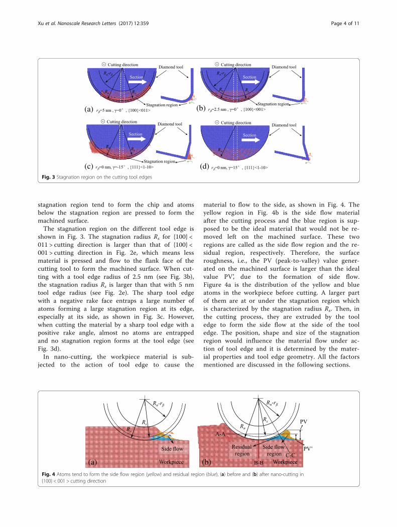
stagnation region tend to form the chip and atomsbelow the stagnation region are pressed to form themachined surface.The stagnation region on the different tool edge is
shown in Fig. 3. The stagnation radius Rs for {100} <011 > cutting direction is larger than that of {100} <001 > cutting direction in Fig. 2e, which means lessmaterial is pressed and flow to the flank face of thecutting tool to form the machined surface. When cut-ting with a tool edge radius of 2.5 nm (see Fig. 3b),the stagnation radius Rs is larger than that with 5 nmtool edge radius (see Fig. 2e). The sharp tool edgewith a negative rake face entraps a large number ofatoms forming a large stagnation region at its edge,especially at its side, as shown in Fig. 3c. However,when cutting the material by a sharp tool edge with apositive rake angle, almost no atoms are entrappedand no stagnation region forms at the tool edge (seeFig. 3d).In nano-cutting, the workpiece material is sub-
jected to the action of tool edge to cause the
material to flow to the side, as shown in Fig. 4. Theyellow region in Fig. 4b is the side flow materialafter the cutting process and the blue region is sup-posed to be the ideal material that would not be re-moved left on the machined surface. These tworegions are called as the side flow region and the re-sidual region, respectively. Therefore, the surfaceroughness, i.e., the PV (peak-to-valley) value gener-ated on the machined surface is larger than the idealvalue PV’, due to the formation of side flow.Figure 4a is the distribution of the yellow and blueatoms in the workpiece before cutting. A larger partof them are at or under the stagnation region whichis characterized by the stagnation radius Rs. Then, inthe cutting process, they are extruded by the tooledge to form the side flow at the side of the tooledge. The position, shape and size of the stagnationregion would influence the material flow under ac-tion of tool edge and it is determined by the mater-ial properties and tool edge geometry. All the factorsmentioned are discussed in the following sections.
(a) (b)
Fig. 4 Atoms tend to form the side flow region (yellow) and residual region (blue), (a) before and (b) after nano-cutting in{100} < 001 > cutting direction
(a) (b)
(c) (d)Fig. 3 Stagnation region on the cutting tool edges
Xu et al. Nanoscale Research Letters (2017) 12:359 Page 4 of 11
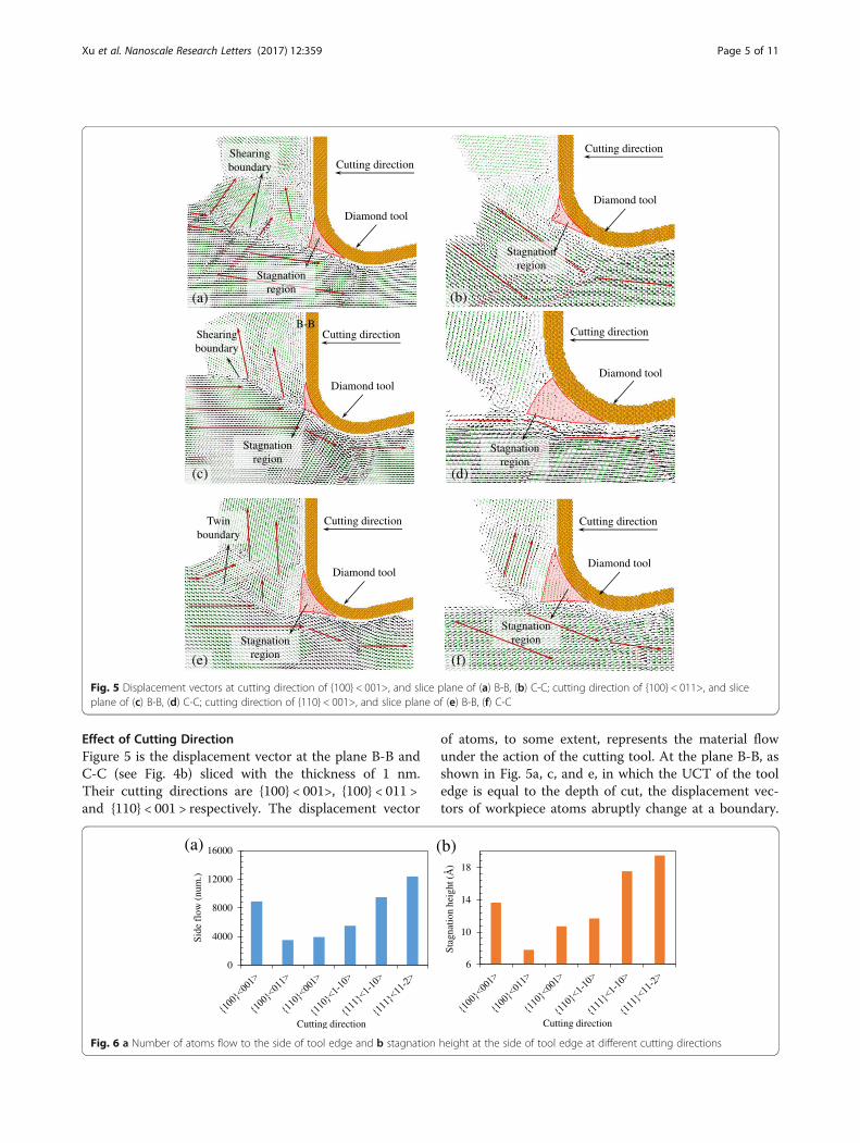
Effect of Cutting DirectionFigure 5 is the displacement vector at the plane B-B andC-C (see Fig. 4b) sliced with the thickness of 1 nm.Their cutting directions are {100} < 001>, {100} < 011 >and {110} < 001 > respectively. The displacement vector
of atoms, to some extent, represents the material flowunder the action of the cutting tool. At the plane B-B, asshown in Fig. 5a, c, and e, in which the UCT of the tooledge is equal to the depth of cut, the displacement vec-tors of workpiece atoms abruptly change at a boundary.
0
4000
8000
12000
16000
Sid
e fl
ow (
num
.)
Cutting direction
(a)
6
10
14
18
Stag
nati
on h
eigh
t (Å
)
Cutting direction
(b)
Fig. 6 a Number of atoms flow to the side of tool edge and b stagnation height at the side of tool edge at different cutting directions
Cutting direction
Diamond tool
Shearing boundary
Stagnationregion
(a)
Cutting direction
Diamond tool
Stagnationregion
(b)
B-BCutting direction
Diamond tool
Stagnationregion
Shearing boundary
(c)
Cutting direction
Diamond tool
Stagnationregion
(d)
Cutting direction
Diamond tool
Stagnationregion
Twin boundary
(e)
Cutting direction
Diamond tool
Stagnationregion
(f)
Fig. 5 Displacement vectors at cutting direction of {100} < 001>, and slice plane of (a) B-B, (b) C-C; cutting direction of {100} < 011>, and sliceplane of (c) B-B, (d) C-C; cutting direction of {110} < 001>, and slice plane of (e) B-B, (f) C-C
Xu et al. Nanoscale Research Letters (2017) 12:359 Page 5 of 11
The boundary is where the plastic deformation occurs.The boundary expands from the tip of the stagnation re-gion which is formed in front of the cutting tool edge.The included angle between the boundary and the cut-ting direction is the shearing angle. The shearing angleof {100} < 001 > cutting direction is smaller than that of{100} < 011 > cutting direction at the snapshots. Theshearing angle of the {110} < 001 > cutting direction isthe largest because it is the twin boundary. The shearingangle of it is about 35°.At the plane C-C, as shown in Fig. 5b, d, and f, it is
the displacement vector of atoms when the UCT is al-most zero, and it is where the side flow tends to occur.At the cutting direction of {100} < 001>, a large numberof atoms are extruded by the tool edge to flow to theflank face of the cutting tool forming the side flow onthe machined surface. However, at the cutting directionof {100} < 011 > and {110} < 001>, a small amount ofatoms are extruded by the tool edge. Therefore, smallerside flow forms on the machined surface. As shown inFig. 6, the size of side flow seems to relate to the stagna-tion radius Rs on the cutting edge. The stagnation heighths which is calculated according to the equation (Rn −Rs), is used to characterize the position of the stagnationregion at the tool edge. As shown in Fig. 6(b), the stag-nation height of the {100} < 001 > cutting direction ishigher than that of the {100} < 011 > and {110} < 001 >cutting directions, which causes a larger side flow. Thenumber of atoms in the side flow region (yellow regionin Fig. 4b) which quantitatively represents the size of theside flow material is counted and shown in Fig. 6a
including all the cutting directions. The side flow is lar-ger for the cutting direction of {100} < 001>, {111} < 1-10 > and {111} < 11-2 > than that of the rest three cuttingdirections. And it is consistent with the stagnationheight hs at each cutting direction, as shown in Fig. 6b.Furthermore, the side flow is influenced by the aniso-
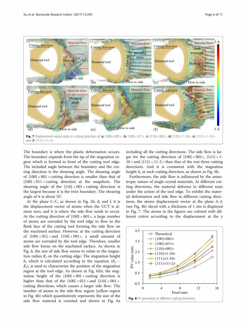
tropic nature of single crystal materials. At different cut-ting directions, the material deforms in different waysunder the action of the tool edge. To exhibit the mater-ial deformation and side flow in different cutting direc-tions, the atoms displacement vector at the plane A-A(see Fig. 4b) sliced with a thickness of 1 nm is displayedin Fig. 7. The atoms in the figures are colored with dif-ferent colors according to the displacement at the y
-0.5
0.5
1.5
2.5
3.5
4.5
0 4 8 12 16
PV v
alue
(nm
)
Feed (nm)
Theoretical{100}<001>{100}<011>{110}<001>{110}<1-10>{111}<1-10>{111}<11-2>
Fig. 8 PV generated at different cutting directions
Diamond tool
Cutting directionMaterial flow
Flow up
Flow to side
{111}
(a)
Diamond tool
Cutting directionMaterial flow
Shearingplane
Flow to side(b)
Diamond tool
Cutting directionMaterial flow
Twinboundary
Flow up
Flow to side(c)
Diamond tool
Cutting direction Material flow
Shearingplane
Flow to side(d)
Diamond tool
Cutting direction Material flow
{111}
Flow to side(e)
Diamond tool
Cutting direction Material flow
{111}
Flow to side
Flow up
(f) -3 Å
3 Å
Fig. 7 Displacement vector plots in cutting direction of (a) {100} < 001>, (b) {100} < 011>, (c) {110} < 001>, (d) {110} < 1–10>, (e) {111} < 1–10 >and (f) {111} < 11–2>
Xu et al. Nanoscale Research Letters (2017) 12:359 Page 6 of 11
direction. Therefore, the atoms displacement vector inthe space could be fully displayed. With the cutting dir-ection of {100} < 001>, the material in front of the cut-ting edge flows up at a triangular region which isbounded by the {111} planes and the cutting edge, asshown in Fig. 7a. Out of the triangular region, large partof material flows to the side of the tool edge. And thenthe side flow which is relatively larger than the cuttingdirection of {100} < 011>, {110} < 001>, and {110} < 1–10>, is formed when the material flows to the flank faceof the cutting tool. Similar results are obtained whencutting on the {111} plane which is a close-packed plane,a large number of atoms flow to the side of tool edge, asshown in Fig. 7e, f. It is because the material is easy toslip on the close-packed plane {111} making large part ofmaterial flow to the side of the tool edge.When cutting with the {100} < 011 > direction whose
side flow is the smallest, atoms do not flow to the sideuntil a small amount of atoms reach the shearing plane.
The flow up region in front of the cutting tool isbounded by the shearing plane which expands from thetip of the stagnation region as shown in Fig. 5c. Similarresults are obtained when cutting with the direction of{110} < 1–10>. But more material flows to the side of thecutting edge forming the relatively larger side flow onthe machined surface. With the cutting direction of{110} < 001>, the shearing plane is the twin boundary, asshown in Fig. 5e, which expands under the tool edge.Therefore, large part of material flow up in front of thetool edge and small part of material flow to the side ofthe tool edge. Thus it can be seen that the side flow isinfluenced by the anisotropic nature of the material. Atdifferent cutting directions, the size of the side flow hasgreat difference which would finally affect the machinedsurface quality. Therefore, the cutting directions of{100} < 011>, {110} < 001>, and {110} < 1–10 > are benefi-cial to obtain a better surface quality. For furtherincreasing the machined surface quality, the feed and
Cutting direction
Diamond tool
(a)
Cutting direction
Diamond tool
(b)
Cutting direction
Diamond tool
(c)
Cutting direction
Diamond tool
(d)
Fig. 10 Displacement vector of atoms at the plane B-B, cutting direction of {111} < 11–2 > and the feed of (a) 1.5 nm and (b) 3.75 nm; (c) and (d)corresponding shear strain
Diamond tool
(a)
Diamond tool
(b)
-0.2Å
0.2Å
Fig. 9 Displacement of atoms at (a) x-direction and (b) y-direction at cutting direction of {111} < 11–2 > and feed of 1.5 nm
Xu et al. Nanoscale Research Letters (2017) 12:359 Page 7 of 11
the tool geometry could be optimized which arediscussed in the next sections.
Effect of FeedThe effect of feed on the side flow and the materialremoval mechanism is investigated by changing the feedfrom 1.5 to 15 nm. The results shown in Fig. 8 are thetheoretical and simulated PV value obtained accordingto Fig. 4. At all different cutting directions, the simulatedPV value is larger than the theoretical value and de-creases with the reduced feed. When the feed is largerthan 8 nm, the PV value of {100} < 011 > and {110} <001 > cutting directions is the smallest. And the largestPV value is obtained at {100} < 001 > and {111} < 11–2 >cutting directions. The PV value of the rest cuttingdirections is in the middle of them and the value of{111} < 1–10 > cutting direction is relatively larger thatthat of {110} < 1–10 > cutting direction. It is consistentwith the number of atoms in the side flow regionshown in Fig. 4a.When the feed is smaller than 8 nm, the PV value of
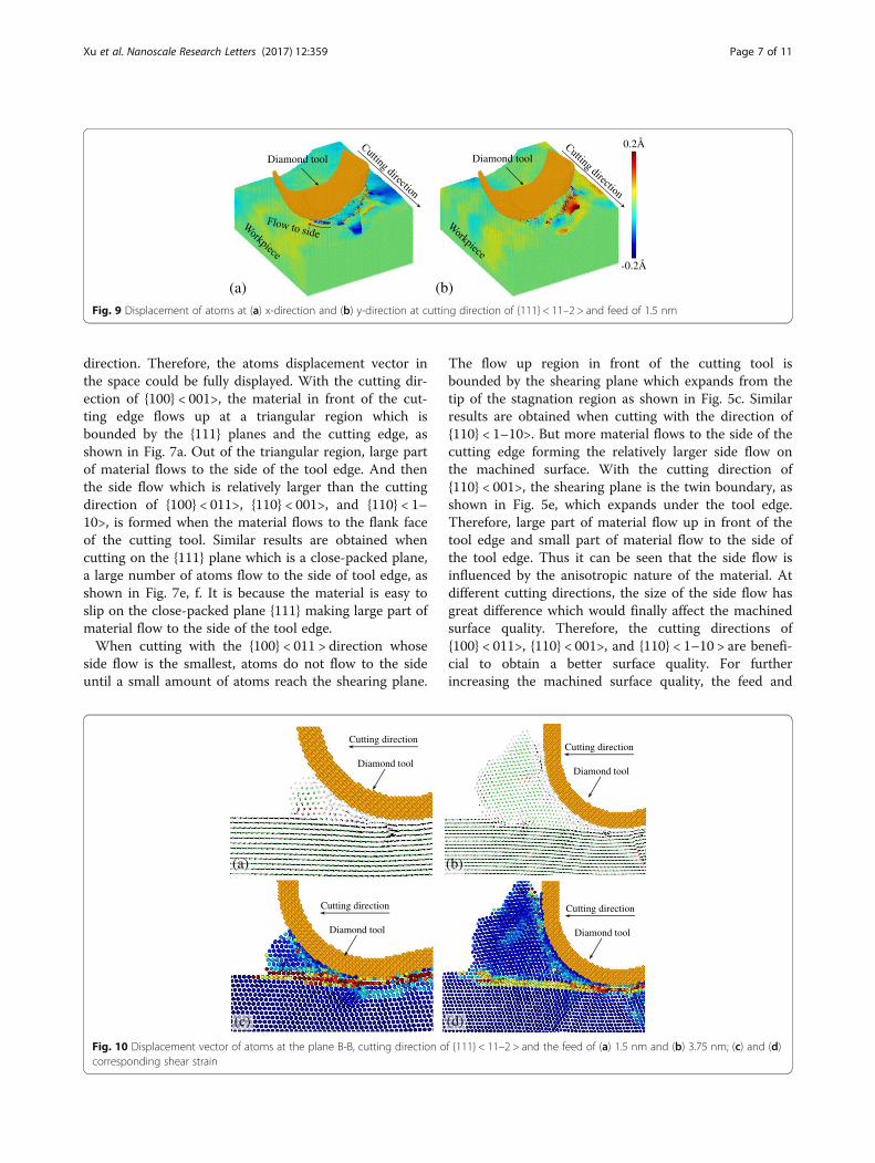
all the cutting directions is close to each other. Mini-mum PV value is not found at which the PV value wouldincrease when further decreases the feed [24]. It is be-cause the cutting distance used in these simulations issmall making the side flow increase slowly. As shown inFig. 9 is the displacement of atoms in x-direction and y-direction at the feed of 1.5 nm. The atoms in front ofthe diamond tool tend to flow to the side and almost noatoms flow up along the rake face of the cutting tool. Ifthe cutting distance is long enough, more atoms wouldbe extruded causing the size of the side flow increases.The displacement vector of atoms at the plane B-B isshown in Fig. 10a, b. When the feed is 1.5 nm, the cut-ting tool is rubbing on the machined surface and almostno atoms are removed. When the feed is 3.76 nm, stag-nation region does not form in front of tool edge and noshearing plane expands from the stagnation region tip,making the material extruded away from the bottomof the cutting edge and forming as chip. In this con-dition, the material is removed in extrusion mechan-ism [13–15]. Figure 10c, d is the corresponding shear
strain distribution of Fig. 10a, b. The results showthat when in the rubbing and extrusion mechanism,the primary deformation zone expands from the bot-tom of the cutting tool edge and just merges with thetertiary deformation zone. In rubbing and extrusionmechanism, the strain zone almost parallels to thecutting direction. The differences between the extru-sion and rubbing mechanism are that the strainhappens at surface or subsurface of the workpiecematerial.
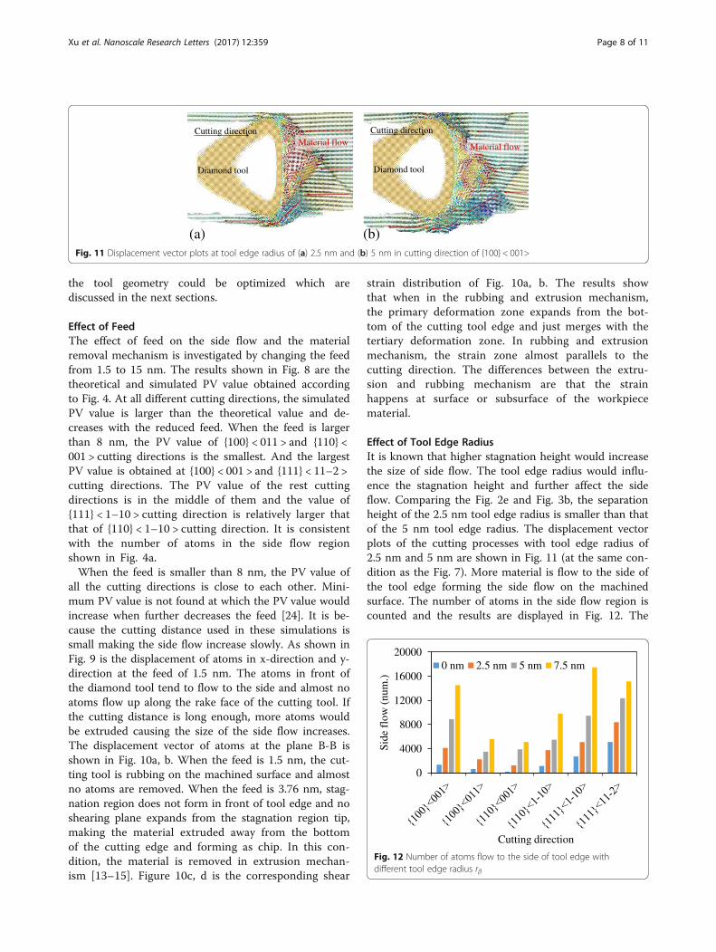
Effect of Tool Edge RadiusIt is known that higher stagnation height would increasethe size of side flow. The tool edge radius would influ-ence the stagnation height and further affect the sideflow. Comparing the Fig. 2e and Fig. 3b, the separationheight of the 2.5 nm tool edge radius is smaller than thatof the 5 nm tool edge radius. The displacement vectorplots of the cutting processes with tool edge radius of2.5 nm and 5 nm are shown in Fig. 11 (at the same con-dition as the Fig. 7). More material is flow to the side ofthe tool edge forming the side flow on the machinedsurface. The number of atoms in the side flow region iscounted and the results are displayed in Fig. 12. The
0
4000
8000
12000
16000
20000
Side
flo
w (
num
.)
Cutting direction
0 nm 2.5 nm 5 nm 7.5 nm
Fig. 12 Number of atoms flow to the side of tool edge withdifferent tool edge radius rβ
Diamond tool
Cutting directionMaterial flow
Diamond tool
Cutting direction
Material flow
(a) (b)Fig. 11 Displacement vector plots at tool edge radius of (a) 2.5 nm and (b) 5 nm in cutting direction of {100} < 001>
Xu et al. Nanoscale Research Letters (2017) 12:359 Page 8 of 11
results show that the sharper tool would decreases thesize of side flow for all the six cutting directions.In nano-cutting, large part of material is under the ac-
tion of the tool edge whose effective rake angle is alwaysnegative regardless of the nominal rake angle is positiveor not [14, 15, 25]. When the tool edge radius increases,more material is under the action of negative rake anglemaking the increase of side flow. Detailed discussionabout the effects of the rake angle on the side flow innano cutting is described in next section.
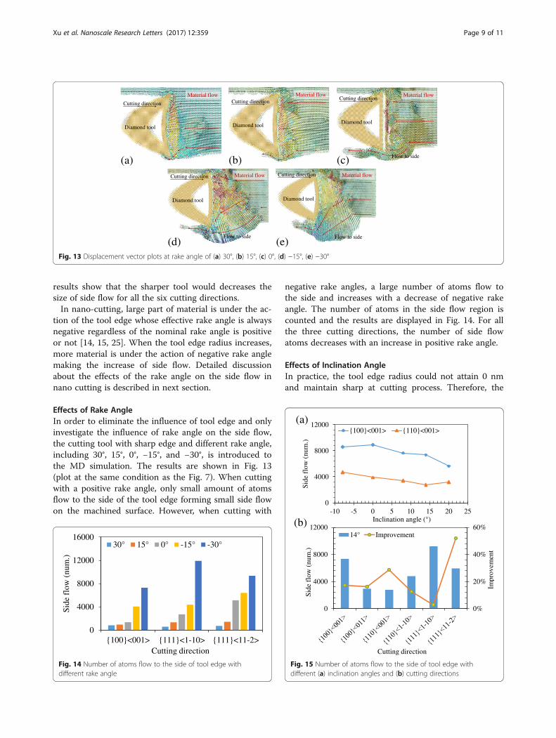
Effects of Rake AngleIn order to eliminate the influence of tool edge and onlyinvestigate the influence of rake angle on the side flow,the cutting tool with sharp edge and different rake angle,including 30°, 15°, 0°, −15°, and −30°, is introduced tothe MD simulation. The results are shown in Fig. 13(plot at the same condition as the Fig. 7). When cuttingwith a positive rake angle, only small amount of atomsflow to the side of the tool edge forming small side flowon the machined surface. However, when cutting with
negative rake angles, a large number of atoms flow tothe side and increases with a decrease of negative rakeangle. The number of atoms in the side flow region iscounted and the results are displayed in Fig. 14. For allthe three cutting directions, the number of side flowatoms decreases with an increase in positive rake angle.
Effects of Inclination AngleIn practice, the tool edge radius could not attain 0 nmand maintain sharp at cutting process. Therefore, the
Diamond tool
Cutting direction
Material flow
(a)
Material flow
Diamond tool
Cutting direction
(b)
Material flow
Diamond tool
Cutting direction
Flow to side(c)
Diamond tool
Cutting direction
Flow to side
Material flow
(d)
Diamond tool
Cutting direction Material flow
Flow to side(e)
Fig. 13 Displacement vector plots at rake angle of (a) 30°, (b) 15°, (c) 0°, (d) −15°, (e) −30°
0
4000
8000
12000
16000
{100}<001> {111}<1-10> {111}<11-2>
Side
flo
w (
num
.)
Cutting direction
30° 15° 0° -15° -30°
Fig. 14 Number of atoms flow to the side of tool edge withdifferent rake angle
0
4000
8000
12000
-10 -5 0 5 10 15 20 25
Side
flo
w (
num
.)
Inclination angle (°)
{100}<001> {110}<001>
0%
20%
40%
60%
0
4000
8000
12000
Impr
ovem
ent
Side
flo
w (
num
.)
Cutting direction
14° Improvement
(b)
(a)
Fig. 15 Number of atoms flow to the side of tool edge withdifferent (a) inclination angles and (b) cutting directions
Xu et al. Nanoscale Research Letters (2017) 12:359 Page 9 of 11
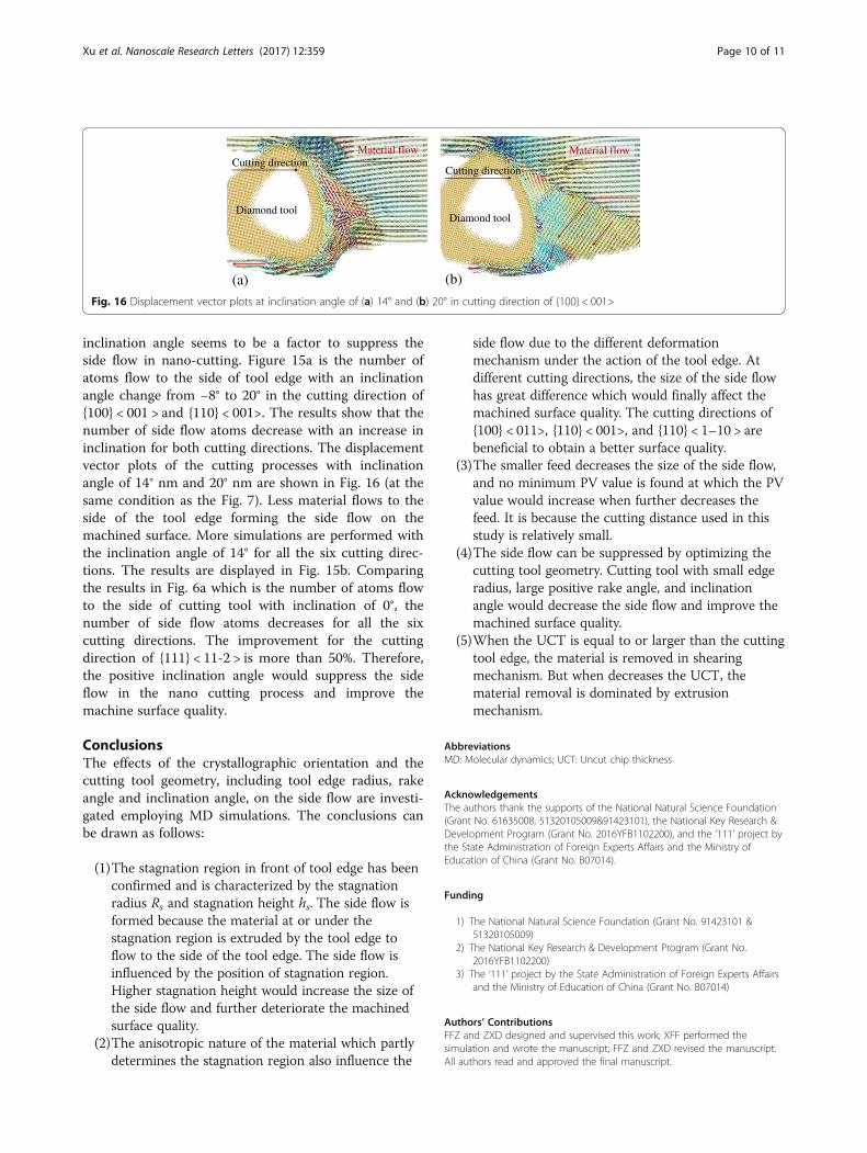
inclination angle seems to be a factor to suppress theside flow in nano-cutting. Figure 15a is the number ofatoms flow to the side of tool edge with an inclinationangle change from −8° to 20° in the cutting direction of{100} < 001 > and {110} < 001>. The results show that thenumber of side flow atoms decrease with an increase ininclination for both cutting directions. The displacementvector plots of the cutting processes with inclinationangle of 14° nm and 20° nm are shown in Fig. 16 (at thesame condition as the Fig. 7). Less material flows to theside of the tool edge forming the side flow on themachined surface. More simulations are performed withthe inclination angle of 14° for all the six cutting direc-tions. The results are displayed in Fig. 15b. Comparingthe results in Fig. 6a which is the number of atoms flowto the side of cutting tool with inclination of 0°, thenumber of side flow atoms decreases for all the sixcutting directions. The improvement for the cuttingdirection of {111} < 11-2 > is more than 50%. Therefore,the positive inclination angle would suppress the sideflow in the nano cutting process and improve themachine surface quality.
ConclusionsThe effects of the crystallographic orientation and thecutting tool geometry, including tool edge radius, rakeangle and inclination angle, on the side flow are investi-gated employing MD simulations. The conclusions canbe drawn as follows:
(1)The stagnation region in front of tool edge has beenconfirmed and is characterized by the stagnationradius Rs and stagnation height hs. The side flow isformed because the material at or under thestagnation region is extruded by the tool edge toflow to the side of the tool edge. The side flow isinfluenced by the position of stagnation region.Higher stagnation height would increase the size ofthe side flow and further deteriorate the machinedsurface quality.
(2)The anisotropic nature of the material which partlydetermines the stagnation region also influence the
side flow due to the different deformationmechanism under the action of the tool edge. Atdifferent cutting directions, the size of the side flowhas great difference which would finally affect themachined surface quality. The cutting directions of{100} < 011>, {110} < 001>, and {110} < 1–10 > arebeneficial to obtain a better surface quality.
(3)The smaller feed decreases the size of the side flow,and no minimum PV value is found at which the PVvalue would increase when further decreases thefeed. It is because the cutting distance used in thisstudy is relatively small.
(4)The side flow can be suppressed by optimizing thecutting tool geometry. Cutting tool with small edgeradius, large positive rake angle, and inclinationangle would decrease the side flow and improve themachined surface quality.
(5)When the UCT is equal to or larger than the cuttingtool edge, the material is removed in shearingmechanism. But when decreases the UCT, thematerial removal is dominated by extrusionmechanism.
AbbreviationsMD: Molecular dynamics; UCT: Uncut chip thickness
AcknowledgementsThe authors thank the supports of the National Natural Science Foundation(Grant No. 61635008, 51320105009&91423101), the National Key Research &Development Program (Grant No. 2016YFB1102200), and the ‘111’ project bythe State Administration of Foreign Experts Affairs and the Ministry ofEducation of China (Grant No. B07014).
Funding
1) The National Natural Science Foundation (Grant No. 91423101 &51320105009)
2) The National Key Research & Development Program (Grant No.2016YFB1102200)
3) The ‘111’ project by the State Administration of Foreign Experts Affairsand the Ministry of Education of China (Grant No. B07014)
Authors’ ContributionsFFZ and ZXD designed and supervised this work; XFF performed thesimulation and wrote the manuscript; FFZ and ZXD revised the manuscript.All authors read and approved the final manuscript.
Material flow
Diamond tool
Cutting direction
(a)
Material flow
Diamond tool
Cutting direction
(b)
Fig. 16 Displacement vector plots at inclination angle of (a) 14° and (b) 20° in cutting direction of {100} < 001>
Xu et al. Nanoscale Research Letters (2017) 12:359 Page 10 of 11

Competing InterestsThe authors declare that they have no competing interests.
Publisher’s NoteSpringer Nature remains neutral with regard to jurisdictional claims inpublished maps and institutional affiliations.
Author details1State Key Laboratory of Precision Measuring Technology and Instruments,Centre of MicroNano Manufacturing Technology, Tianjin University, Tianjin300072, China. 2Institute of Mechanical Manufacturing Technology, ChinaAcademy of Engineering Physics, Sichuan 621900, China. 3School ofMechanical and Materials Engineering, MNMT-Dublin, University CollegeDublin, Dublin, Ireland.
Received: 24 March 2017 Accepted: 10 May 2017
References1. Saurav G, Alexander S, Xichun L, Anupam A, Robert LR (2013) Anisotropy of
single-crystal 3C-SiC during nanometric cutting. Model Simul Mater Sci Eng21:065004
2. To S, Lee WB, Chan CY (1997) Ultraprecision diamond turning of aluminiumsingle crystals. J Mater Process Technol 6:157–162
3. Lee WB, To S, Cheung CF (2000) Effect of crystallographic orientation indiamond turning of copper single crystals. Scr Mater 42:937–945
4. Tauhiduzzaman M, Veldhuis SC (2014) Effect of material microstructure andtool geometry on surface generation in single point diamond turning.Precis Eng 38:481–491
5. Zong WJ, Li ZQ, Zhang L, Liang YC, Sun T, An CH, Zhang JF, Zhou L, WangJ (2013) Finite element simulation of diamond tool geometries affecting the3D surface topography in fly cutting of KDP crystals. Int J Adv ManufTechnol 68:1927–1936
6. Zhang G, To S, Zhang S (2016) Relationships of tool wear characteristics tocutting mechanics, chip formation, and surface quality in ultra-precision flycutting. Int J Adv Manuf Technol 83:133–144
7. Kishawy HA, Elbestawi MA (1999) Effects of process parameters on materialside flow during hard turning. Int J Mach Tool Manuf 39:1017–1030
8. Liu K, Melkote SN (2006) Effect of plastic side flow on surface roughness inmicro-turning process. Int J Mach Tool Manuf 46:1778–1785
9. Pekelharing A, Gieszen C (1971) Material side flow in finish turning. AnnCIRP 20:21–22
10. Kishawy HA, Haglund A, Balazinski M (2006) Modelling of Material Side Flowin Hard Turning. CIRP Ann 55:85–88
11. He CL, Zong WJ, Sun T (2016) Origins for the size effect of surfaceroughness in diamond turning. Int J Mach Tool Manuf 106:22–42
12. Furukawa Y, Moronuki N (1988) Effect of Material Properties on Ultra PreciseCutting Processes. CIRP Ann 37:113–116
13. Fang FZ, Venkatesh VC (1998) Achieving threshold barrier of 1 nm roughnessvalue of silicon surface by diamond turning. Chin J Mech Eng 11:6–10
14. Fang FZ, Wu H, Zhou W, Hu XT (2007) A study on mechanism of nano-cutting single crystal silicon. J Mater Process Technol 184:407–410
15. Fang FZ, Liu B, Xu ZW (2015) Nanometric cutting in a scanning electronmicroscope. Precis Eng 41:145–152
16. Ding X, Jarfors AEW, Lim GC, Shaw KC, Liu YC, Tang LJ (2012) A study of thecutting performance of poly-crystalline oxygen free copper with singlecrystalline diamond micro-tools. Precis Eng 36:141–152
17. Thiele JD, Melkote S (1999) Effect of cutting edge geometry and workpiecehardness on surface generation in the finish hard turning of AISI 52100steel. J Mater Process Technol 94:216–226
18. Schaal N, Kuster F, Wegener K (2015) Springback in metal cutting with highcutting speeds. Procedia CIRP 31:24–28
19. Yi K, Tr Ö (2008) Mechanics of high speed cutting with curvilinear edgetools. Int J Mach Tool Manuf 48:195–208
20. Denkena B, Biermann D (2014) Cutting edge geometries. CIRP Ann 63:631–65321. Lai M, Zhang XD, Fang FZ (2012) Study on critical rake angle in nanometric
cutting. Appl Phys A 108:809–81822. Kountanya RK, Endres WJ (2001) A high-magnification experimental study of
orthogonal cutting with edge-honed tools. Proceedings of 2001 ASMEInternational Mechanical Engineering Congress and Exposition, New York.http://citeseerx.ist.psu.edu/viewdoc/summary?
23. Merchant ME (1945) Mechanics of the metal cutting process. I. orthogonalcutting and a type 2 chip. J Appl Phys 16:267–275
24. Wu X, Li L, Zhao M, He N (2015) Experimental investigation of specificcutting energy and surface quality based on negative effective rake angle inmicro turning. Int J Adv Manuf Technol 82:1941–1947
25. Lai M, Zhang X, Fang F, Wang Y, Feng M, Tian W (2013) Study onnanometric cutting of germanium by molecular dynamics simulation.Nanoscale Res Lett 8:1–10
Xu et al. Nanoscale Research Letters (2017) 12:359 Page 11 of 11