Embed Size (px)
Citation preview

© 2019 Littelfuse, Inc.Specifications are subject to change without notice.
Revised: 03/05/19
GEN2 SiC Schottky Diode
SiC Schottky Diode
LSIC2SD065E40CCA, 650 V, 40 A, TO-247-3L
LSIC2SD065E40CCA 650 V, 40 A SiC Schottky Barrier Diode
Features
• AEC-Q101 qualified
• Positive temperature coefficient for safe operation and ease of paralleling
• 175 °C. maximum operating junction temperature
• Excellent surge capability
• Extremely fast, temperature-independent switching behavior
• Dramatically reduced switching losses compared to Si bipolar diodes
Maximum Ratings
Characteristics Symbol Conditions Value Unit
Repetitive Peak Reverse Voltage VRRM - 650 V
DC Blocking Voltage VR TJ = 25 °C 650 V
Continuous Forward Current(Per Leg/Component) IF
TC = 25 °C 45 / 90A
TC = 135 °C 20 / 40
Non-Repetitive Forward Surge Current (Per Leg) IFSM TC = 25 °C, TP = 10 ms, Half sine pulse 90 A
Power Dissipation(Per Leg/Component) PTot
TC = 25 °C 135 / 270W
TC = 110 °C 60 / 120
Operating Junction Temperature TJ - -55 to 175 °C
Storage Temperature TSTG - -55 to 150 °C
Soldering Temperature Tsold - 260 °C
Description
Circuit Diagram TO-247-3LApplications
• Boost diodes in PFC or DC/DC stages
• Switch-mode power supplies
• Uninterruptible power supplies
• Solar inverters
• Industrial motor drives
• EV charging stations
• Littelfuse “RoHS” logo = RoHS conform
• Littelfuse “HF” logo = Halogen Free
• Littelfuse “Pb-free” logo = Pb-free lead plating
Environmental
RoHS
Pb
PIN 1
PIN 2
PIN 3
CASE
1 2 3
This series of silicon carbide (SiC) Schottky diodes has negligible reverse recovery current, high surge capability, and a maximum operating junction temperature of 175 °C. This diode series is ideal for applications where improvements in efficiency, reliability, and thermal management are desired.
RoHS Pb

© 2019 Littelfuse, Inc.Specifications are subject to change without notice.
Revised: 03/05/19
GEN2 SiC Schottky Diode
SiC Schottky Diode
LSIC2SD065E40CCA, 650 V, 40 A, TO-247-3L
Characteristics Symbol ConditionsValue
UnitMin. Typ. Max.
Forward Voltage VF
IF = 20 A, TJ = 25 °C - 1.5 1.8V
IF = 20 A, TJ = 175 °C - 1.85 -
Reverse Current IR
VR = 650 V, TJ = 25 °C - <1 50μA
VR = 650 V, TJ = 175 °C - 60 -
Total Capacitance C
VR = 1 V, f = 1 MHz - 960 -
pFVR = 200 V, f = 1 MHz - 120 -
VR = 400 V, f = 1 MHz - 86 -
Total Capacitive Charge QC VR = 400 V, - 63 - nC
Electrical Characteristics (TJ = 25 °C unless otherwise specified)
Thermal Characteristics
Characteristics Symbol Value Unit
Thermal Resistance (Per Leg/Component) RθJC1.10 / 0.55 °C/W
Qc =
VR
C(V)dV∫0
Figure 1: Typical Foward Characteristics Figure 2: Typical Reverse Characteristics
0
2
4
6
8
10
12
14
16
18
20
0 0.25 0.5 0.75 1 1.25 1.5 1.75 2
Cu
rre
nt (
A)
Voltage (V)
TJ = -55 °CTJ = 25°CTJ = 125 °CTJ = 150 °C
°CTJ = 175

© 2019 Littelfuse, Inc.Specifications are subject to change without notice.
Revised: 03/05/19
GEN2 SiC Schottky Diode
SiC Schottky Diode
LSIC2SD065E40CCA, 650 V, 40 A, TO-247-3L
Figure 5: Capacitance vs. Reverse Voltage
Figure 4: Current Derating Figure 3: Power Derating
Figure 6: Capacitive Charge vs. Reverse Voltage
Figure 7: Stored Energy vs. Reverse Voltage Figure 8: Transient Thermal Impedance
Nor
mal
ized
Tra
nsie
nt Th
erm
al Im
peda
nce
Pulse Width (s)
1E-3
1E-2
1E-1
1E+0
1E-6 1E-5 1E-4 1E-3 1E-2 1E-1 1E+0
0.5
0.3
0.1
0.05
0.02
Single
0.01

© 2019 Littelfuse, Inc.Specifications are subject to change without notice.
Revised: 03/05/19
GEN2 SiC Schottky Diode
SiC Schottky Diode
LSIC2SD065E40CCA, 650 V, 40 A, TO-247-3L
Package Dimensions TO-247-3L
R0.93
5.44 5.44
2.46
Recommended Hole Pattern Layout
UNIT: mm
E
E1
A
A2 D2
D1ØP
ØP1
E2/2
E2
Q S
cA1
DL
L1
b2 (2x)
eb4
b (3x)e
OPTIONAL
Notes:1. Dimensions are in millimeters2. Dimension D, E do not include mold flash. Mold flash shall not exceed 0.127 mm per side. These measured at the outermost extreme of plastic body.3.øP to have a maximum draft angle of 1.5° to the top of the part with a maximum hole diameter of 0.154”
SymbolMillimeters
Min Nom MaxA 4.80 5.03 5.20
A1 2.25 2.38 2.54
A2 1.85 1.98 2.11
b 0.99 - 1.40
b2 1.65 - 2.39
b4 2.59 - 3.43
c 0.38 0.64 0.89
D 20.80 20.96 21.34
D1 13.50 - -
D2 0.51 1.19 1.35
e 5.44 BSC
E 15.75 15.90 16.13
E1 13.06 14.02 14.15
E2 4.19 4.32 4.83
L 19.81 20.19 20.57
L1 3.81 4.19 4.45
øP 3.55 3.61 3.66
øP1 7.06 7.19 7.32
Q 5.49 5.61 6.20
S 6.05 6.17 6.30
Packing Options
Part Number Marking Packing Mode M.O.Q
LSIC2SD065E40CCA SIC2SD065E40CC Tube (30pcs) 450
Part Numbering and Marking System
SIC 2 SD
E = TO-247-3L
Y WW X ZZZZZZ-ZZ
065
CC
SIC2SD065E40CC
YWWXZZZZZZ-ZZ
LF
= SiC
= Schottky Diode= Voltage Rating (650 V)
= Gen2
= Current Rating (40 A)
= Week= Special Code= Lot Number
= Year
40 = Common Cathode
© 2019 Littelfuse, Inc.Specifications are subject to change without notice.
Revised: 03/05/19
GEN2 SiC Schottky Diode
SiC Schottky Diode
LSIC2SD065E40CCA, 650 V, 40 A, TO-247-3L
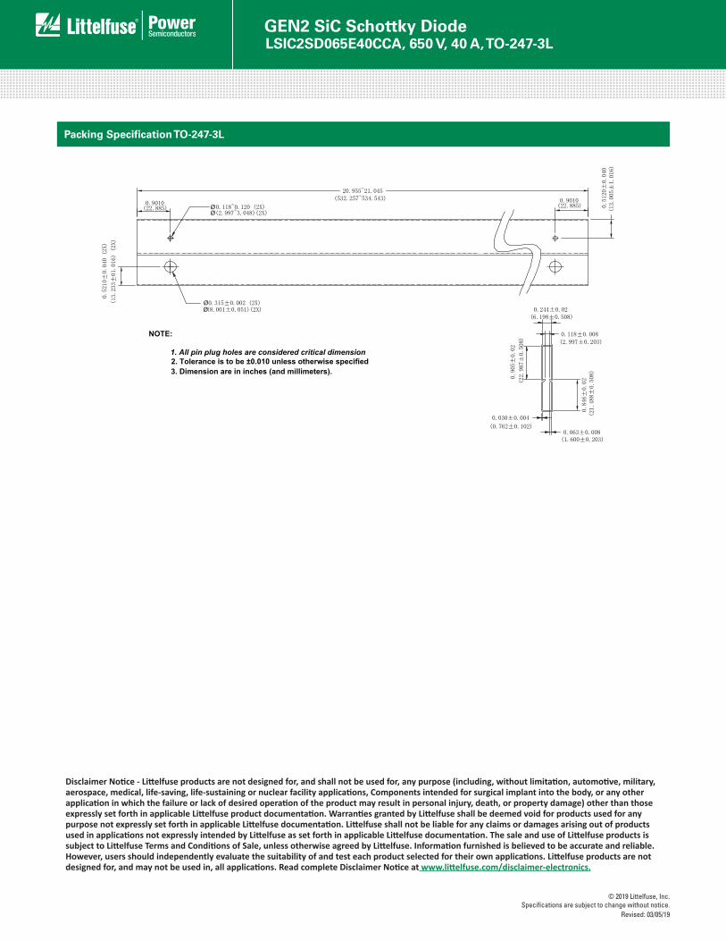
Packing Specification TO-247-3L
Ø
NOTE:
1. All pin plug holes are considered critical dimension2. Tolerance is to be ±0.010 unless otherwise specified3. Dimension are in inches (and millimeters).
Ø
Ø
Ø
Disclaimer Notice - Littelfuse products are not designed for, and shall not be used for, any purpose (including, without limitation, automotive, military, aerospace, medical, life-saving, life-sustaining or nuclear facility applications, Components intended for surgical implant into the body, or any other application in which the failure or lack of desired operation of the product may result in personal injury, death, or property damage) other than those expressly set forth in applicable Littelfuse product documentation. Warranties granted by Littelfuse shall be deemed void for products used for any purpose not expressly set forth in applicable Littelfuse documentation. Littelfuse shall not be liable for any claims or damages arising out of products used in applications not expressly intended by Littelfuse as set forth in applicable Littelfuse documentation. The sale and use of Littelfuse products is subject to Littelfuse Terms and Conditions of Sale, unless otherwise agreed by Littelfuse. Information furnished is believed to be accurate and reliable. However, users should independently evaluate the suitability of and test each product selected for their own applications. Littelfuse products are not designed for, and may not be used in, all applications. Read complete Disclaimer Notice at www.littelfuse.com/disclaimer-electronics.