Embed Size (px)
Citation preview
SiC MOSFET 45W Flyback Converter Application Note, Rev. 1.0 Page 1 of 12
AZ-SiC-EVB-FB-45W SiC MOSFET 45W Flyback Converter
SiC MOSFET 45W Flyback Converter 碳化硅MOSFET 45W 反激变换器
AZ-SiC-EVB-FB-45W
About this document
Scope and purpose This application note provides an overview of the evaluation board AZ-SiC-EVB-FB-45W including its main
features, key data, pin assignments and mechanical dimensions. AZ-SiC-EVB-FB-45W is a complete evaluation board including one SiC power switching devices, synchronous rectifier that is composed of multiple Si MOSFET and an output Si MOSFET. In combination with the on-board controllers, it features and demonstrates AZ Power’s SiC MOSFETs for data center and telecom power supply applications.
The evaluation board AZ-SiC-EVB-FB-45W was developed to support customers to speed up their product development during their initial hardware design with the SiC power devices. The used SiC power device has a rated blocking voltage of 1200 V. It is optimized for quasi-resonant flyback converters with very high switching frequency operation. Intended audience
This application note is intended for power electronic engineers who want to evaluate the performance of SiC devices in soft-switching flyback converter applications.
SiC MOSFET 45W Flyback Converter Application Note, Rev. 1.0 Page 2 of 12
AZ-SiC-EVB-FB-45W SiC MOSFET 45W Flyback Converter
Table of Contents
About this document ............................................................................................................................................... 1
1. Safety Precautions ........................................................................................................................................... 3
2. Introduction ...................................................................................................................................................... 4
3. Design features ................................................................................................................................................. 6
3.1. Detailed Specifications of The Evaluation Board ........................................................................................... 7
3.2. Functional Groups ............................................................................................................................................. 8
3.3. Power Interface Pin Assignment .................................................................................................................... 10
3.4. Sensing for Closed-loop Control ................................................................................................................... 11
4. Revision History ............................................................................................................................................. 12
SiC MOSFET 45W Flyback Converter Application Note, Rev. 1.0 Page 3 of 12
AZ-SiC-EVB-FB-45W SiC MOSFET 45W Flyback Converter
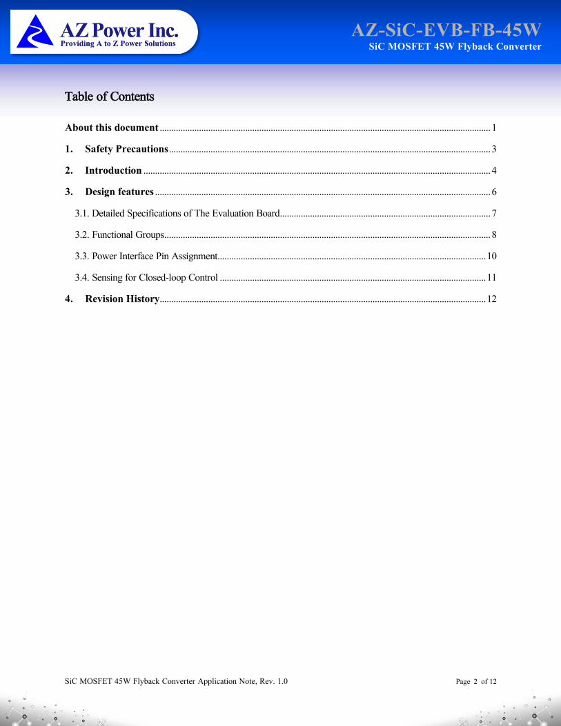
1. Safety Precautions
CAUTION: DURING THE OPERATION OF THE BOARD
DO NOT TOUCH THE EVALUATION BOARD WHEN IT IS POWERED BY ANY EXTERNAL POWER
SOURCE. AND NEVER LEAVE THE EVALUATION BOARD UNATTENDED. THERE MAY HAVE VERY
HIGH VOLTAGE PRESENTS ON THE EVALUATION BOARD.
CAUTION: BEFORE OPERATING THE BOARD
THE EVALUATION BOARD MAY PRESENTS HIGH VOLTAGE DURING OPERATION. THE BULKY
CAPACITORS WILL BE CHARGED BY EXTERNAL POWER SUPPLIES. BEFORE OPERATING THE BOARD,
WAIT FOR 10 SECONDS TO ALLOW THE POWER SUPPLIES TO FULLY CHARGE ALL THE CAPACITORS
AND GET THE WHOLE SYSTEM READY FOR OPERATION.
CAUTION: AFTER POWERING DOWN THE BOARD
THE EVALUATION BOARD MAY PRESENTS HIGH VOLTAGE DURING OPERATION. THE BULKY
CAPACITORS WILL BE CHARGED BY EXTERNAL POWER SUPPLIES. BEFORE WORKING ON THE
EVALUATION BOARD, ALLOW THE BULKY CAPACITORS DISCHARGING FOR THREE MINUTES.
CAUTION: MEASUREMENT
WHEN MEASUREMENT EQUIPMENT ARE ABOUT TO CONNECT TO THE EVALUATION BOARD, USE
HIGH-VOLTAGE DIFFERENTIAL PROBES. IF PASSIVE PROBES ARE INTENDED TO BE USED FOR
MEASUREMENT, CONSULT POWER ELECTRONICS PROFESSIONALS FIRST. DO NOT CONNECT THE
PROBE WHEN THE EVALUATION BOARD IS POWERED BY POWER SOURCE.
CAUTION: CONSEQUENCES
PLEASE MAKE SURE THAT ALL MENTIONED SAFETY PROCEDURES ARE FOLLOWED WHEN USING
THE EVALUATION BOARD. FAILED TO FOLLOW THE INSTRUCTIONS MAY LEAD TO:
• DEATH
• HEAT BURN
• SERIES INJURY
• ELECTROCUTION
• ELECTRICAL SHOCK
• ELECTRICAL BURN
SiC MOSFET 45W Flyback Converter Application Note, Rev. 1.0 Page 4 of 12
AZ-SiC-EVB-FB-45W SiC MOSFET 45W Flyback Converter
2. Introduction
The AZ-SiC-EVB-FB-45W evaluation board is designed for the portable power adaptor and auxiliary power supply application, based on quasi-resonant flyback converter topology. The quasi-resonant flyback converter board is equipped with on-board controllers, on both of the primary side and secondary side of the evaluation board. An additional control board is not needed.
This evaluation board is designed as an easy-to-use power stage based on AZ Power's Silicon Carbide power devices. The evaluation board includes a main power connector for connecting the high voltage AC line, a main power connector for connecting the low voltage DC output, EMI filter, bulky capacitors, transformer and flyback converter power stage. The power stage also contains control circuits.
The AZ-SiC-EVB-FB-45W evaluation board is available via regular AZ Power distribution partners as well as on AZ Power's website. The features of this board can be found in the design feature chapter of this document. The remaining paragraphs provide information enabling customers to copy, modify and qualify the design for production according to their own specific requirements.
Environmental conditions were considered in the design of the AZ-SiC-EVB-FB-45W. The design was tested as described in this document, but not qualified in terms of safety requirements, manufacturing and operation over the entire operating temperature range or lifetime. The boards provided by AZ Power are subject to functional testing only. Evaluation boards are not subject to the same procedures as regular products regarding returned material analysis, process change notification and product discontinuation. Evaluation boards are intended to be used under laboratory conditions and by trained specialists only.
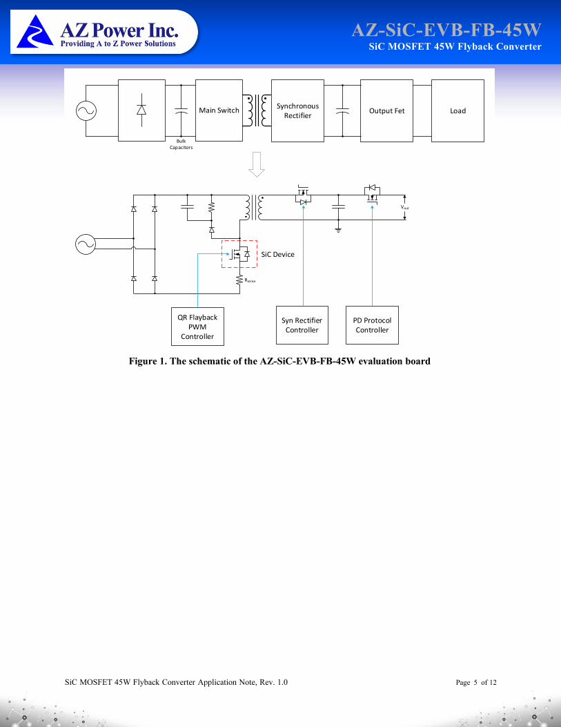
The block diagram of the AZ-SiC-EVB-FB-45W is depicted in Figure 1. This evaluation board includes EMI filters, one primary side PWM controller, one secondary side synchronous rectifier controller, current sensing circuits and quasi-resonant flyback converter composed by silicon carbide semiconductor. All the important control signals can be measured and observed via test points on the evaluation board. The hardware circuit relative to overcurrent protection is implemented through the controller ICs.
The signal processing circuitry of the evaluation board is fully isolated from the power circuitry by using optocouplers. The design may be easily upgraded to a circuitry safe electrical insulation by replacing the present MOSFET drivers, opto-coupler and the controller ICs that meets the safety requirement.
SiC MOSFET 45W Flyback Converter Application Note, Rev. 1.0 Page 5 of 12
AZ-SiC-EVB-FB-45W SiC MOSFET 45W Flyback Converter
Main Switch
Bulk Capacitors
Synchronous Rectifier
Output Fet Load
SiC Device
Rsense
QR Flayback PWM
Controller
Syn Rectifier Controller
Vout
PD Protocol Controller
Figure 1. The schematic of the AZ-SiC-EVB-FB-45W evaluation board
SiC MOSFET 45W Flyback Converter Application Note, Rev. 1.0 Page 6 of 12
AZ-SiC-EVB-FB-45W SiC MOSFET 45W Flyback Converter
3. Design features
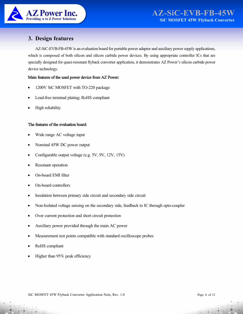
AZ-SiC-EVB-FB-45W is an evaluation board for portable power adaptor and auxiliary power supply applications, which is composed of both silicon and silicon carbide power devices. By using appropriate controller ICs that are specially designed for quasi-resonant flyback converter application, it demonstrates AZ Power’s silicon carbide power device technology.
Main features of the used power device from AZ Power:
• 1200V SiC MOSFET with TO-220 package
• Lead-free terminal plating; RoHS compliant
• High reliability
The features of the evaluation board:
• Wide range AC voltage input
• Nominal 45W DC power output
• Configurable output voltage (e.g. 5V, 9V, 12V, 15V)
• Resonant operation
• On-board EMI filter
• On-board controllers
• Insulation between primary side circuit and secondary side circuit
• Non-Isolated voltage sensing on the secondary side, feedback to IC through opto-coupler
• Over current protection and short circuit protection
• Auxiliary power provided through the main AC power
• Measurement test points compatible with standard oscilloscope probes
• RoHS compliant
• Higher than 95% peak efficiency
SiC MOSFET 45W Flyback Converter Application Note, Rev. 1.0 Page 7 of 12
AZ-SiC-EVB-FB-45W SiC MOSFET 45W Flyback Converter
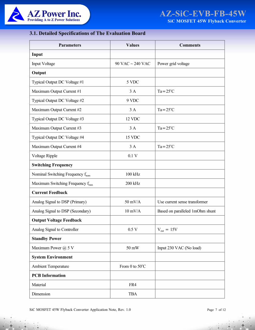
3.1. Detailed Specifications of The Evaluation Board
Parameters Values Comments
Input
Input Voltage 90 VAC ~ 240 VAC Power grid voltage
Output
Typical Output DC Voltage #1 5 VDC
Maximum Output Current #1 3 A Ta=25°C
Typical Output DC Voltage #2 9 VDC
Maximum Output Current #2 3 A Ta=25°C
Typical Output DC Voltage #3 12 VDC
Maximum Output Current #3 3 A Ta=25°C
Typical Output DC Voltage #4 15 VDC
Maximum Output Current #4 3 A Ta=25°C
Voltage Ripple 0.1 V
Switching Frequency
Nominal Switching Frequency fnom 100 kHz
Maximum Switching Frequency fmax 200 kHz
Current Feedback
Analog Signal to DSP (Primary) 50 mV/A Use current sense transformer
Analog Signal to DSP (Secondary) 10 mV/A Based on paralleled 1mOhm shunt
Output Voltage Feedback
Analog Signal to Controller 0.5 V Vout = 15V
Standby Power
Maximum Power @ 5 V 50 mW Input 230 VAC (No load)
System Environment
Ambient Temperature From 0 to 50°C
PCB Information
Material FR4
Dimension TBA
SiC MOSFET 45W Flyback Converter Application Note, Rev. 1.0 Page 8 of 12
AZ-SiC-EVB-FB-45W SiC MOSFET 45W Flyback Converter
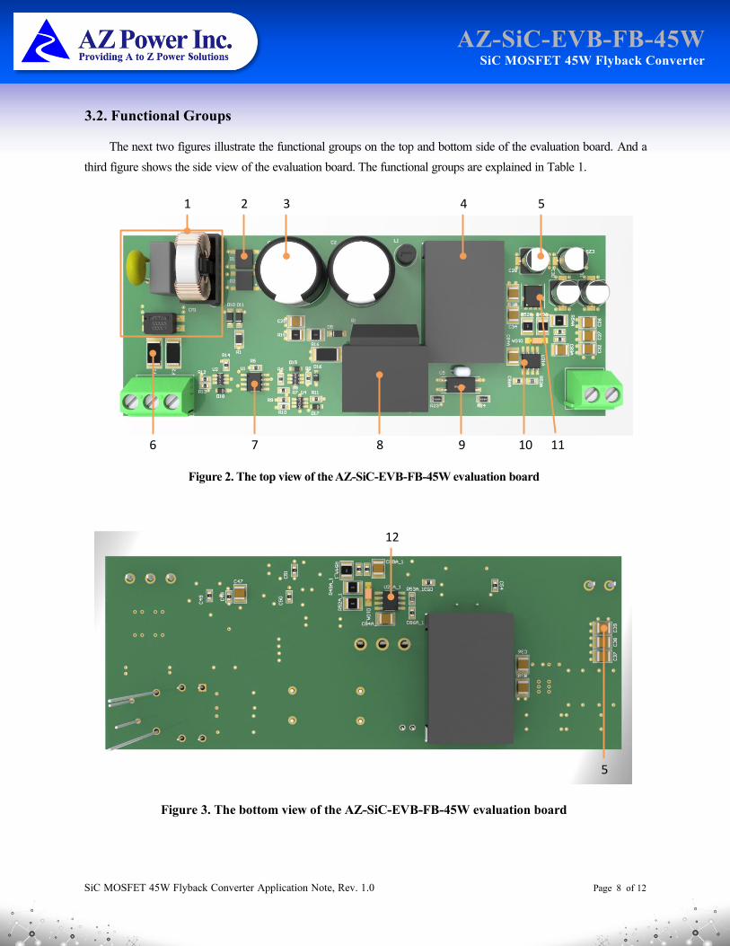
3.2. Functional Groups
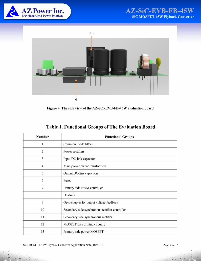
The next two figures illustrate the functional groups on the top and bottom side of the evaluation board. And a third figure shows the side view of the evaluation board. The functional groups are explained in Table 1.
3 4 51
6 8 9 11
2
7 10
Figure 2. The top view of the AZ-SiC-EVB-FB-45W evaluation board
12
5
Figure 3. The bottom view of the AZ-SiC-EVB-FB-45W evaluation board
SiC MOSFET 45W Flyback Converter Application Note, Rev. 1.0 Page 9 of 12
AZ-SiC-EVB-FB-45W SiC MOSFET 45W Flyback Converter
Table 1. Functional Groups of The Evaluation Board
Number Functional Groups
1 Common mode filters
2 Power rectifiers
3 Input DC-link capacitors
4 Main power planar transformers
5 Output DC-link capacitors
6 Fuses
7 Primary side PWM controller
8 Heatsink
9 Opto-coupler for output voltage feedback
10 Secondary side synchronous rectifier controller
11 Secondary side synchronous rectifier
12 MOSFET gate driving circuitry
13 Primary side power MOSFET
13
4
Figure 4. The side view of the AZ-SiC-EVB-FB-45W evaluation board
SiC MOSFET 45W Flyback Converter Application Note, Rev. 1.0 Page 10 of 12
AZ-SiC-EVB-FB-45W SiC MOSFET 45W Flyback Converter
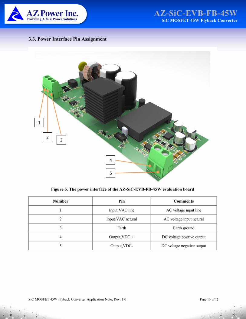
3.3. Power Interface Pin Assignment
Number Pin Comments
1 Input_VAC line AC voltage input line
2 Input_VAC netural AC voltage input netural
3 Earth Earth ground
4 Output_VDC+ DC voltage positive output
5 Output_VDC- DC voltage negative output
1
23
4
5
Figure 5. The power interface of the AZ-SiC-EVB-FB-45W evaluation board
SiC MOSFET 45W Flyback Converter Application Note, Rev. 1.0 Page 11 of 12
AZ-SiC-EVB-FB-45W SiC MOSFET 45W Flyback Converter
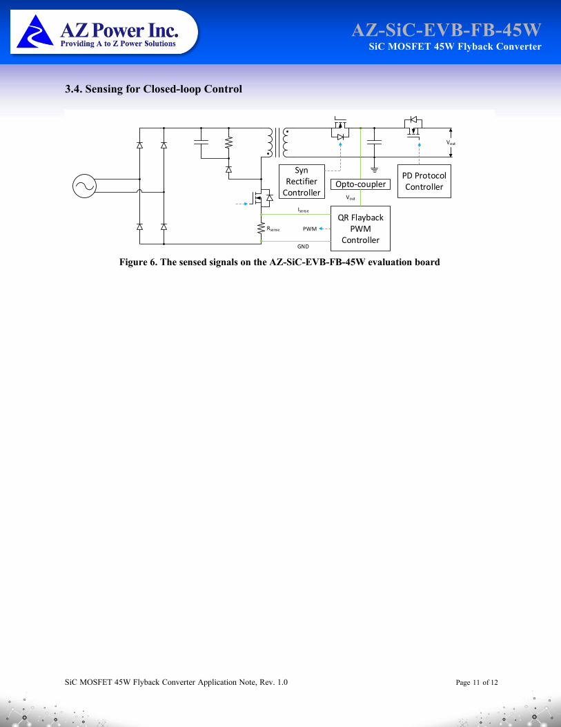
3.4. Sensing for Closed-loop Control
Rsense
QR Flayback PWM
Controller
Vout
GND
Isense
Vout
Opto-coupler
PWM
Syn Rectifier
Controller
PD Protocol Controller
Figure 6. The sensed signals on the AZ-SiC-EVB-FB-45W evaluation board

SiC MOSFET 45W Flyback Converter Application Note, Rev. 1.0 Page 12 of 12
AZ-SiC-EVB-FB-45W SiC MOSFET 45W Flyback Converter
4. Revision History
Document version Description of change
1.0 Initial version
This Product has not been designed or tested for use in, and is not intended for use in, applications implanted into the human body
nor in applications in which failure of the product could lead to death, personal injury or property damage, including but not limited to equipment used in the operation of nuclear facilities, life-support machines, systems, or air-traffic control systems.
The information given in this document shall in no event be regarded as a guarantee of conditions or characteristics. With respect to any examples, hints or any typical values stated herein and/or any information regarding the application of the product, AZ Power Inc. disclaims any and all warranties and liabilities of any kind, including without limitation warranties of non-infringement of intellectual property rights of any third party.
5601 W SLAUSON AVE 190
CULVER CITY, CA 90230
WWW.AZPE.COM
Information in this document may change without notice. All referenced product or service names and trademarks are the property of their respective owners. Copyright © 2020 AZ Power Inc. All rights reserved.


![Catalogue FLYBACK Equivalent - [PDF Document] FLYBACK Equivalent FlyBack Equivalent flyback reemplazo conversor Flyback tv fly-back Flyback Tester Flyback Converter conversor Flyback](https://img.pdfslide.us/doc/110x75/5a832a447f8b9a9d308e9416/catalogue-flyback-equivalent-pdf-document-flyback-equivalent-flyback-equivalent.jpg)