Embed Size (px)
Citation preview
20100224-0467 FERC PDF (Unofficia1) 02/03/2010
SI AlE OF CALIFORNIA - IHE RESOURCES AGENCY AINOLD SCHWAIZENEGGEI. GOver.
JAN 1'1 ZO.
DEPARTMENT OF WATER RESOURCES1416 NINTH STREET.P.O. BOX 942836SACRAMENTO. CA 9423~1(916) 653-5791
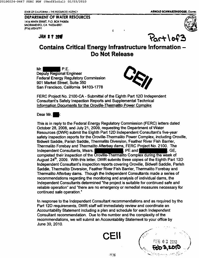
Contains Critical Energy Infrastructure Information -Do Not Release
Mr. P.E.Deputy Regional EngineerFederal Energy Regulatory Commission901 Market Street, Suite 350San Francisco, California 94103-1778
FERC Project No. 2100-CA - Submittal of the Eighth Part 120 IndependentConsultant's Safety Inspection Reports and Supplemental TechnicalInformation Documents for the Oroville- Thermalito Power Complex
Dear Mr. :
This is in reply to the Federal Energy Regulatory Commission (FERC) letters datedOctober 28,2008, and July 21,2009, requesting the Department of WaterResources (DWR) submit the Eighth Part 120 Independent Consultant's five-yearsafety inspection reports for the Oroville-Thermalito Power Complex, including Oroville,Bidwell Saddle, Parish Saddle, Thermalito Diversion, Feather River Fish Barrier,Thermalito Forebay and Thermalito Afterbay dams, FERC Project No. 2100. TheIndependent Consultants, Mssrs. PE and GE,completed their inspection of the Oroville- Thermalito Complex during the week ofAugust 24th, 2009. With this letter, DWR submits three copies of the Eighth Part 120Independent Consultant's inspection reports covering Oroville, Bidwell Saddle, ParishSaddle, Thermalito Diversion, Feather River Fish Barrier, Thermalito Forebay andThermalito Afterbay dams. Though the Independent ConSUltants made a series ofrecommendations regarding the monitoring and analysis of individual dams, theIndependent ConSUltants determined "the project is suitable for continued safe andreliable operation" and "there are no emergency or remedial measures necessary forcontinued safe operation."
In response to the Independent Consultant recommendations and as required by thePart 120 requirements, DWR staff will immediately review and coordinate anAccountability Statement including a plan and schedule for each IndependentConsultant recommendation. Due to the number and the complexity of therecommendations, we will submit an Accountability Statement to your office byJune 30,2010.
CEil...
.·.1...• .:~:~~.•".
20100224-0467 FERC PDF (Unofficia1) 02/03/2010
Mr. , P.E.'1It4 I' 20mPage 2
DWR also submits three copies of our revised Standard Technical InformationDocument (STID) for each dam within the Oroville-Thermalito Power Complex. Uponyour receipt of the new STID's, DWR requests that each 2005 STID be replaced withthe new version and that the 2005 STID's be either returned to DWR or destroyed.
DWR staff revised the STID's to include updated technical analyses as well asincorporating the recommendations from the 2005 Seventh Part 12D IndependentConsultant's five-year safety inspection reports. The revised STID's do not containaddendums to the 2005 Potential Failure Mode Analysis (PFMA), though a PFMA auditwas conducted on September 17, 2009, with the Eighth Part 12D IndependentConsultants. DWR will submit the PFMA update to your office under a separatecover-letter, as will any other updates made to the STID's per the Eighth Part 12DIndependent Consultant recommendations.
If you have any questions or would like to discuss this further, please contact me at, or your staff may contact , Chief of DWR's Dam Safety
Branch at
Sincerely,
Chief, Hydropower License Planning and ComplianceExecutive Division
Enclosures
20100224-0467 FERC PDF (Unofficial) 02/03/2010
IJGEl Consultants
GeotechnicalEnvironmental and
Water ResourcesEngineering
Oroville DamFERC Project 2100-CAState DamNo. 1-048NID No. CA00035, CA00530 andCA83096
Eighth Five-Year Part 12D SafetyInspection ReportSubmitted· to:California Department of Water ResourcesDivision of Operations and Maintenance1416 9th Street, P.O. Box 942836Sacfamento, CA 95814
Prepared By:GEl Consultants, Inc.180 Grand Avenue, Suite 1410Qakland, CA 94612-3017
January 2010Project 09202-0
CEil •• CRITICAL ENERGY INFRASTRUCTUREINFORMATION in accordance with 18 CFR§ 388.112.DO NOT COPY, RELEASE, OR OTHERWISEDISTRIBUTE.
20100224-0467 FERC PDF (Unofficia1) 02/03/2010
-- Oroville Damcalifornia Department of Water R_ourceeJanuary 2OtO-- Findinas and Recommendations 1-1
-
1.1 Findings 1-1loLl Summary Assessment or"the PFMA report 1-11.1.2 Summary Assessment of the Surveillance and Monitoring Plan 1-21.1.3 Summary of Field Inspection Findings 1-31.1.4 Summary of O&M Status 1-3Ll.5 Summary Assessment of "Supporting Technical Information"
Document.. 1-31.2 Conclusions ; 1-4
1.2.1 Conclusions Regarding the Suitability of the Project for ContinuedSafe and Reliable Operation 1-4
1.2.2 Conclusions Regarding the Project Description 1-41.2.3 Conclusions Regarding the PFMA Report 1-41.2.4 Conclusions Regarding the Surveillance and Monitoring Plan I-41.2.5 Conclusions Regarding the Field Inspection 1-51.2.6 Conclusions Regarding the Operation and Maintenance Programs 1-51.2.7 Conclusions Regarding the Supporting Technical Information
Document. 1-51.3 Recommendations 1-5
1.3.1 Recommendations Regarding the Suitability of the Project forContinued Safe and Reliable Operation 1-5
1.3.2 Recommendations Regarding the Project Description 1-61.3.3 Recommendations Regarding the PFMA Report 1-61.3.4 Recommendations Regarding the Surveillance and Monitoring
Plan (SMP) 1-61.3.5 Recommendations Regarding the Field Inspection 1-61.3.6 Recommendations Regarding the Operation and Maintenance
Programs 1-71.3.7 Recommendations Regarding the Supporting Technical
Information Document 1-71.4 Certification 1-7
1.4.1 List of all Field Inspection Participants (August 25, 26 and 27,2009) 1-8
1.4.2 Reference to FERC Order 122 dated March 1, 1981 and paragraph12.37(c)(7) 1-8
1.4.3 Limitation of Liability 1-91.4.4 Signature of Part 120 Co-Independent Consultants and PE Stamp 1-9
----------------------
Project Description 2-1-- 2.1 Brief Project Description 2-12.1.1 Dams 2-12.1.2 Spillways 2-32.1.3 Intakes and Conveyance System 2-4
---GEl Consultants, Inc.CEII- CRITICAL ENERGY INFIWITRIIClURE INFORIoIATIONln '... CRlllIIU1lI.DO NOT COPY, RELEASE, OR OTHE"-DISIIIIIIUIL
Project 09202-0----
20100224-0467 FERC PDF (Unofficia1) 02/03/2010
-- Oroville DamCallfarnla Deparlmenl 01Water R.... urcesJanuary 2010-
-
2.1.4 Powerhouse 2-42.1.5 Low Level Outlets 2-5
2.2 Hazard Potential Classification 2-52.3 Summary of Standard Operating Procedures 2-5
2.3.1 Purpose of Project.. 2-52.3.2 Reservoir Rule Curves and Operating Restrictions 2-62.3.3 Standard Gate Operation Procedures 2-6
2.4 Modifications Conducted for Project Safety 2-72.5 Flood History 2-9
2.5.1 Flood of Record, PMF, IDF 2-92.5.2 Zero Freeboard Spillway Capacity 2-102.5.3 Peak Spillway Discharge During Last Five Year Period 2-102.5.4 Peak Reservoir Elevation During Last Five Year Period 2-1O
--------
Discussion of Potential Failure Mode AnalysisReport 3-1
- 3.1 General 3-13.2 Assessment of Potential Failure Mode Analysis Report 3-23.3 Other Potential Failure Modes 3-3--- Surveillance and Monitoring with Respect toPotential Failure Modes 4-1
-4.1 Operator's Surveillance Program .4-14.2 Active Instrumentation 4-2
4.2.1 Piezometers and Pore Pressure Measurements .4-34.2.2 Weirs .4-44.2.3 Settlement/Alignment Monuments .4-54.2.4 Crack Gauges .4-54.2.5 Upstream River and/or Rain Gauge Stations .4-64.2.6 Headwaterffailwater (Alarm Systems) 4-64.2.7 Seismic Monitoring 4-6
4.3 Threshold and Action levels '" 4-64.4 Reading ProceduresIFrequency .4-7
4.4.1 Data Acquisition ProceduresIFrequency .4-74.4.2 Data Evaluation Procedures .4-74.4.3 Procedures for Spurious Readings .4-8
4.5 Assessment of Instrumentation Data and Surveillance and MonitoringPlans Relative to Potential Failure Modes 4-8
4.6 Assessment of Instrumentation Data ..........................•......................................4-94.6.1 Piezometers .4-94.6.2 Weirs .4-94.6.3 Survey Monuments .4-104.6.4 Crack Gages .4-10
-------------
GEl Consultants, Inc. ii Project ()9202A-- CEII- CRmCAL ENERGY INFRAIITRUI:nR auGS&&i1..... _ ........ GIl..... CMI-.n2.DO NOT COPY, RELEASE, OR onu II_II .JIE.--
-20100224-0467 FERC PDF (Unofficia1) 02/03/2010
- Oroville DamCalifornia Department of Wala. R.... urceaJanuary 2010-...
---...--.--- §:.------ 1.:.---....----...-
4.6.5 Upstream river and/or rain gage stations .4-lO4.6.6 Reservoir Level.. .4-11
Field Inspection 5-15.1 Field Inspection Observations 5-1
5.1.1 General.. 5-15.1.2 Dam 5-15.1.3 Spillway 5-35.1.4 Low-Level Outlets 5-45.1.5 Intake (Photos 34 to 35) 5-55.1.6 (Photo 39) 5-55.1.7 Hyatt Powerhouse (Photos 38 to 40) 5-55.1.8 Reservoir Rim Stability 5-5
5.2 Status of Response(s) to Recommendation(s) in Last Part 12DReport 5-55.3 Field Observations with Respect to Potential Failure Modes 5-95.4 Adequacy/Operation of Public Alert Systems 5-9
Operation and Maintenance Programs Relative toPotential Failure Modes 6-16.1 Summary PFMA Identified O&M Issues (from PFMA report) 6-16.2 Operation and Maintenance Procedures 6-2
6.2.1 Communication/Response 6-2
6.3 Assessment ofO&M Procedures Relative to Potential Failure Modes 6-4
Assessment of Supporting Technical InformationDocument 7-17.1 Potential Failure Mode Analysis Study Report 7-17.2 Project Description and Drawings 7-17.3 Construction History 7-27.4 Standard Operating Procedures 7-27.5 Geology and Seismicity 7-3
7.5.1 Site Geology 7-37.5.2 Landslides 7-47.5.3 Faulting and Seismicity 7-57.5.4 Geology and Seismicity Summary 7-7
7.6 Hydrology and Hydraulics 7-77.6.1 Hydrology Studies 7-77.6.2 Spillway Structure - Concrete Assessment.. 7-9
7.7 Surveillance and Monitoring Program 7-107.8 Stability and Stress Analyses of Project Structures 7-1O
7.8.1 Existing Stability Analysis 7-10
iii Project 09202-0- GEl Consultanta, Inc.- CElI- CRITICAL EHERGY INFRASTRuc:ftIIIE INFORMATION In .CI'II,......DO NOTCGP\', - E'SE, OROTHE_1llUR18UTE.-...
20100224-0467 FERC PDF (Unofficia1) 02/03/2010
-- Oroville DamCalifornia Department of Water Rl80urcasJanulU'y 20t 0-
-
7.8.2 Adequacy of Existing Stability Analyses 7-117.9 Spillway Gates 7-13
7.9.1 Stress Analysis 7-137.9.2 Radial Gate Testing 7-147.9.3 Structural Inspections and Trunnion Evaluation 7-157.9.4 Ultrasonic Inspections 7-15
7.10 Pertinent Correspondence Related to Safety of Project Works 7-167.11 Status of Studies in Process and Outstanding Issues 7-167.12 References 7-177.13 Conclusions 7-17
------- List of Figures (See Appendix C)
List of References-- Appendices:
A. FERC Letter Requiring Part 120 InspectionB. FERC Letter Approving ConsultantC. Project FiguresD. Instrumentation Location Figures and Data PlotsE. Inspection Photographs- August 25.26 and 27.2009F. Inspection ChecklistG. Operation and Maintenance Documentation
---------------".- GEl Consultants, Inc. iv
CEII- CRIllCALENERGYINFRASTRIIC:naX = ..... ...... =.1188112.DO IlaT caPt'. RELEASE. OR OTHE__ U '1E.
Project 09202-0--...
20100224-0467 FERC PDF (Unofficia1) 02/03/2010
-- Oroville DamcalHornla Depulment of Water ReaourceaJanuary 201 0- 1. Findings and Recommendations--- 1.1 Findings
- Oroville is part of the Oroville- Thermalito Complex, FERC Project No. 2100, which alsoincludes Edward Hyatt Powerplant, Thermalito Diversion Dam and Powerplant, FeatherRiver Fish Barrier Dam, Feather River Fish Hatchery, Thermalito Power Canal,Thermalito Forebay· Dam and Pump-Generation Plant, and Thermalito Afterbay Dam. Inall, the Oroville- Thermalito Complex stores approximately 3.6 million acre-ft andgenerates power from releases through three powerplants.
----
-
Beginning at the upstream end of the Oroville- Thermalito Complex, water released fromLake Oroville is used to produce electricity at the Edward Hyatt Powerplant, or may bedirectly released into the Thermalito Diversion pool. At Thermalito Diversion Dam thewater from Lake Oroville then is used to produce electricity at Thermalito DiversionPowerplant and enters the Feather River directly; or is diverted into the Thermalito PowerCanal which leads to the Thermalito Forebay. At the end of the Forebay, water dischargesdirectly into the Thermalito Afterbay or is used to generate power at the ThermalitoPump-Generation Plant before entering the Thermalito Afterbay.
--
-The Oroville portion of the complex consists of Oroville Dam, Edward Hyatt Powerplant,Hyatt Powerplant Intake, Bidwell Bar Canyon Saddle Dam, Parish Camp Saddle Dam,Flood Control and Emergency Spillways,
---- Oroville Dam, Parish Camp Saddle Dam and Bidwell Bar Canyon Saddle Dam are all
classified as a "High Hazard Potential" under FERC guidelines ...- 1.1.t Summary Assessment of the PFMA report-- The Potential Failure Modes Analysis (PFMA) workshop for Oroville Dam was held on
September 15, 2004. The "Potential Failure Modes Analysis Study Report" for OrovilleDam was prepared by HDR and Geomatrix Consultants, Inc. (Reference 70) using DraftChapter 14 of the FERC Engineering Guidelines (April 13, 2(03) and conforms ingeneral to the current FERC Engineering Guidelines Chapter 14 (dated July 1,2(05) .
-.-..- The 2004 PFMA workshop. resulted in the identification of only one potential failure
mode (PFM) for consideration and evaluation. The PFM related to core material pipingthat extends downstream leading to
failure of the dam. After discussion, this PFM was classified as Category IV-Ruled Out.---- GEl CoMUltants, Inc. 1-1 Project 09202-0... CEIl- = nc...... ENERGYINFRASTRUCTUREINFORMAnONIn accordII.- _ 1. CFR 1318.112 •
1ID..ra..; "EASE, OR OTHERWISEDISTRIBUTE.-...
20100224-0467 FERC PDF (Unofficia1) 02/03/2010
- Oroville DamCalifornia Deparlment 01 Wilier R.... u......January 2010
- Several other potential scenarios were discussed, but were ruled out since they wereconsidered to be non-viable or too remote of a possibility. Due to special interest in theissue based on past evaluations and discussions and onthe suggestion of the facilitator, several potential failure modes considered but not carriedforward as credible potential failure modes were documented as "Candidates" (ratherthan being discussed in the Other Considerations - Section 7) in order to facilitateunderstanding of the issue and illustrate the comprehensive consideration of this topic bythe PFMA team.
...-...--- As part of the 2010 Eighth Part 12D safety review,.a one-day workshop (covering all the
OroviIIe-Thermalito Project) was conducted to review the PFMs developed during the2004 PFMA workshops to determine if they remain appropriate or if there are any thathave been omitted or should be reclassified. During the 2009 PFMA Update workshop,an additional Potential Failure Mode for Oroville was proposed and discussed.
-...--- 1.1.2 Summary Assessment of the Surveillance and Monitoring Plan--
Staff from the Field Division observe the facilities seven days a week during theirmonitoring activities and collect surveillance instrument data from the facilities on aweekly basis.-
-An extensive array of instruments was installed at Oroville Dam, Flood Control Outletstructure, and Hyatt Powerplant to monitor performance during and after originalconstruction. At Oroville Dam, the instruments consisted of twin tube piezometers,
, various types of electrical strain meters and pressure transducers, fluidlevel and cross arm settlement devices, extensometers, seismic sensors, seepagemeasuring weirs, and survey monument markers. To date, most of the twin tubepiezometers and fluid level settlement monitoring devices located in the damembankment are no longer functional and have been abandoned in place. Only five of the56 original hydraulic piezometers installed in Oroville Dam during construction arefunctional and only three are providing reliable data; over 95 percent of the piezometershave failed. Most of the instrumentation was installed to monitor Oroville Damperformance during initial reservoir filling and for the initial 5 or more years ofoperation. The principle surveillance program monitoring is currently limited to seismic,seepage and settlement/deflection measurements. We believe for a dam of this size andpotential consequence of Oroville, a plan for long-term monitoring of the phreatic surfacewithin the dam embankment needs to be developed and implemented.
---------...
GEl Consultants, Inc.- Project 09202-0CElI- CRI1ICALENERGYINFRASTRIICTIa ............. ... I.CFR 1388.112-DONOTCXIPr, RELEASE,OR OTHERW.Wi' "IV..--...
20100224-0467 FERC PDF (Unofficia1) 02/03/2010
-- OrovIlle DamCalifornia Depar1menl at Walar RlI8Ou.....January 2010
1.1.3 Summary of Field Inspection Findings..
-
There were no conditions observed during the Part 120 field inspection conducted onAugust 25, 26 and 27,2009 that require emergency remedial action. The dam is beingwell operated by DWR and project structures appear adequately maintained. Based uponour field observations, Oroville Dam and its appurtenant structures are in goodcondition. There are no emergency or remedial measures necessary for continued safeoperation. DWR is doing a good job of maintaining the dam, auxiliary dams, RoodControl Outlet, intake, powerhouse, and other appurtenant structures. Most of thespecific findings in Section 5 are facility maintenance items, as DWR has currentcontracts and improvement work on the Rood Control Outlet spillway concrete chute
The physical condition of the twin tube piezometertubes in House T are deteriorating.
--------1.1.4 Summary of O&M Status-- Overall, our evaluation of the facility is that all operation and maintenance is beingperformed to an acceptable level, with some specific recommendations listed below in1.3.
...-- 1.1.5 Summary Assessment of "Supporting Technical Information"
Document---
The Supporting Technical Information Document (STID) for the Oroville Dam wasoriginally drafted by HDR and Geomatrix Consultants, Inc. in conjunction with the 2005Part 12D Safety Inspection Report (Reference 58) and finalized by DWR in June 2009(Reference 70). We have reviewed the STID and believe that it provides an adequatesummary of the available background information on the dam and related projectfacilities. The STID conforms in general to the FERC Engineering Guideline Chapter 14(dated July I, 2(05). Based on our review of the STID, discussions with DWR staff andour August 2009 field inspection, several suggested updates to the STID were identified.These updates are described in Section 7. Specific recommendations are given in Section\.3.7 .
----...------ GEl Consultants. Inc. 1-3 Project 08202-0- CEII- CIIJIICAL ENERGY INFRASTRUCTURE INFORMATION In lCCOrd8nce _ 1aCfRlalllLn2.
DONOT...,; - "IE, OROTHE~""'''''''--
20100224-0467 FERC PDF (Unofficia1) 02/03/2010.-- OrovIlle DamCalifornia Department 01Wilier ReeourceeJanuory 2010
- 1.2 Conclusions-- 1.2.1 Conclusions Regarding the Suitability of the Project for ContinuedSafe and Reliable Operation--.. The project is suitable for continued safe and reliable operation. There are no emergency
or remedial measures necessary for continued safe operation.-- 1.2.2 Conclusions Regarding the Project Description
- In general, the project description is adequate. Several suggested enhancements to theproject description in the STID are given in Section 7.2.-1.2.3 Conclusions Regarding the PFMA Report...
-The PFMA report meets the FERC requirements. No Category I-Highlighted PFMs wereidentified. There was only one PFM postulated during the 2004 PFMA workshop, whichwas subsequently ruled out. As part of the 2010 Eighth Part 12D safety review, a one-dayworkshop (covering all the Oroville- Thermalito Project) was conducted to review thePFMs developed during the 2004 PFMA workshops to determine if they remainappropriate or if there are any that have been omitted or should be reclassified. The 2004PFMA report and 2009 workshop are discussed in more detail in Section 3.
----- Based upon review of existing information and discussions in the PFMA workshop, we
conclude the PFMA report and addendum are adequate and cover the range of viablepotential failure modes identified for Oroville Dam,-
- 1.2.4 Conclusions Regarding the Surveillance and Monitoring Plan
-.. Due to Oroville Dam's size, water supply importance and potential consequence of afailure, a plan for long-term monitoring of the phreatic surface within the damembankment needs to be developed and implemented. In order to evaluate embankmentbehavior and performance under long term steady-seepage and unusual or extremeloading events, it will be necessary to monitor the dam's phreatic surface and porewaterpressure at several sections, upstream to downstream. While the original twin tubepiezometer network appears to have adequately served its useful purpose, the need forongoing piezometric monitoring does not end with the obsolescence of the system.Monitoring intemal porewater, pressures, and phreatic surfaces will give the engineergreatest insight into the behavior and performance of an embankment dam. In particularthe combined readings of piezometric level, seepage, and acceleration time history allows
-..-----...
GEl Can8uitants. Inc. 1-4- Project 09202-0
ca-.,.....~GY INFRASTRUCTIIRIEE:INFO::I::-••U.... • with 18 CFR, -.11Z.ID IIGI"GDP\'. - "BE, OR OTHERWISEDIs I srr.---
20100224-0467 FERC PDF (Unofficia1) 02/03/2010
- Oroville DamCalifornIa Department 01WaI8r R.... urcasJanuary 2010- for a deeper understanding and evaluation of embankment performance during and aftersignificant seismic events. We consider the need to assess the instrumentationrequirements and monitoring plan to be essential for this major dam.
--- 1.2.5 Conclusions Regarding the Field Inspection-.-
There were no conditions observed during the Part 12D field inspection conducted onAugust 25, 26 and 27, 2009 that require emergency remedial action.-
- 1.2.6 Conclusions Regarding the Operation and Maintenance Programs
--
Operation and maintenance for the project is being performed to an acceptable level.There are several outstanding issues regarding inspections, operation and maintenancewhich are discussed in Section 7.11.
--- 1.2.7 Conclusions Regarding the Supporting Technical Information
Document-
-
We have reviewed the STID and believe that it provides an adequate summary of theavailable background information on the dam and related project facilities. The STIDconforms in general to the FERC Engineering Guideline Chapter 14 (dated July 1,2(05).Based on our review of the STID, discussions with DWR staff and our August 2009 fieldinspection, several additional studies are recommended as discussed in Section 1.3.7below. In addition, several suggested updates to the STID were identified. These updatesare described in Section 7 herein.
----
1.3 Recommendations-- 1.3.1 Recommendations Regarding the Suitability of the Project forContinued Safe and Reliable Operation--
-None. The project is suitable for 'continued safe and reliable operation. There are noemergency or remedial measures necessary for continued safe operation.-
------ GEl Consultanta, Inc. 1·5- CEil - CRITICAL ENERGY INFRASTRUCTURE INFORMAnON In ... __ n.. with 18 CFR .... nz.DO NOT COPY, RELEAlE. OR OTHERWISE DISTRIBUTE.--
20100224-0467 FERC PDF (Unofficia1) 02/03/2010
-- OrovIlle DamCalifornia Departmenl 01W_ RnourceaJenUllry 1010- 1.3.2 Recommendations Regarding the Project Description-- See Sections 1.3.7 and 7.13 below for recommendations regarding the project descriptionin the STID.-- 1.3.3 Recommendations Regarding the PFMA Report-- None. The 2004 PFMA Report and the 2009 PFMA Addendum are adequate.
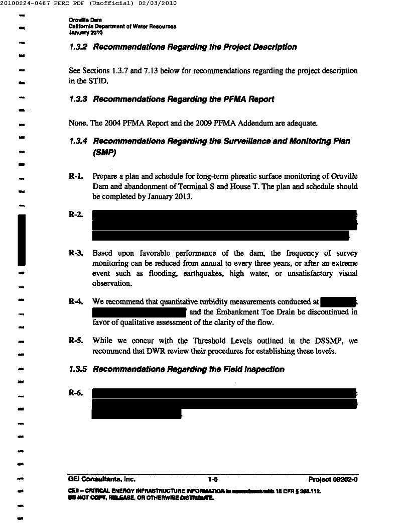
1.3.4 Recommendations Regarding the Surveillance and Monitoring Plan(SMP)
---- R·t. Prepare a plan and schedule for long·term phreatic surface monitoring of OrovilleDam and abandonment of Terminal S and House T. The plan and schedule shouldbe completed by January 2013.--
R·2.
-R·3. Based upon favorable performance of the dam, the frequency of survey
monitoring can be reduced from annual to every three years, or after an extremeevent such as flooding, earthquakes, high water, or unsatisfactory visualobservation.
-R-4. We recommend that quantitative turbidity measurements conducted at
and the Embankment Toe Drain be discontinued infavor of qualitative assessment of the clarity of the flow.
--- R·S. While we concur with the Threshold Levels outlined in the DSSMP, we
recommend that DWR review their procedures for establishing these levels.-- 1.3.5 Recommendations Regarding the Field Inspection-- R·6.-----GEl Consultanta, Inc. 1-6.. Project 09202·0
c:&Il- CRI'IICAL ENERGY INFRASTRUCTURE INFORIiA1IQ.U._ .. _' .... ,. CFR 1388.112 •..lICIT CIIIPf, - 'ME, OR OTHERWISEOIS'IRIBUIW.
---
20100224-0467 FERC PDF (Unofficia1) 02/03/2010
-- OroviliaDamCaliforniaoa,,-ent 01Water R.... u......Jlnuary 201 0-- 1.3.6 Recommendations Regarding the Operation and Maintenance
Programs--
R-7. DWR should establish a regular plan and schedule for periodic inspection andevaluation of the radial gates (including the trunnion pins). Refer to FERC letterdated December 18, 2009 (Ref. 71) for FERC requirements. This plan andschedule should be completed by January 2011.
----
R·8. DWR conducted a structural inspection of the Flood Control Outlet radial gates in1997 and several recommendations were made. A follow-up of theserecommendations should be investigated and a schedule of actions prepared byJanuary 2011, if necessary.
--- 1.3.7 Recommendations Regarding the Supporting Technicsllnformation
Document--- R·9. As discussed in Section 7.5, we recommend that an updated seismic hazardassessment be performed for the Oroville-Thermalito Complex. This should becompleted by January 2013.--- R·IO. We recommend an evaluation of the adequacy of the spillway to pass the designflood event (PMF) be presented in a single volume report considering thecomments made in Section 7.6.1. This should be completed by January 2014.--
-R·ll. We recommend a comprehensive review of the stability analyses on record,
considering the factors listed in Section 7.8, to determine whether the existingstudies remain valid in view of modern practices. Based on this review, the needfor updated seismic stability analyses should be determined. This should becompleted by January 2014.
---- R·12. We recommend structural evaluation of the Flood Control Outlet radial gates for
PMF loading conditions for two scenarios indicated in Section 7.9. This should becompleted by January 2013.-...
- R·13. We suggest several updates to the STID as listed in Section 7.13. These should becompleted by January 2014.-- 1.4 Certification- By signing this document we state that the entire report has been developed by and under
the direction of the undersigned and we concur (unless noted) with the assumptions,methods of analyses, and results of all studies documented in the report.
-..- GEl Consultants, Inc. 1·7- Project 09202-0
CEII- CRITICALBlERGY INfRASTRuc:n.e I.aRMAlDlIa wIIII,aCFRf-'ftZ.DO NOT«:mIW; -"', _GIIIE~"_ua.-..
20100224-0467 FERC PDF (Unofficia1) 02/03/2010
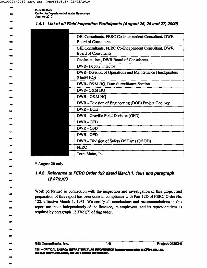
-.. Or",,",_ Damcalifornia Daparbnanl 01Walllr Raaou.....January 2010- 1.4.1 List of all Field Inspection Participants (August 25, 26 and 27, 2009)-- GEl Consultants, FERC Co-Independent Consultant, DWR
Board of Consultants
GEl Consultants, FERC Co-Independent Consultant, DWRBoard of Consultants
Geoinsite, Inc., DWR Board of Consultants
DWR- Deputy Director
DWR- Division of Operations and Maintenance Headquarters(O&MHQ)
DWR- O&M HQ, Dam Surveillance Section
DWR-O&MHQ
DWR-O&MHQ
DWR - Division of Engineering (DOE) Project Geology
DWR·DOE
DWR - Oroville Field Division (OFD)
DWR-OFD
DWR-OFD
DWR-OFD
DWR - Division of Safety Of Dams (DSOD)
FERC
Terra Mater, Inc.
..-..---------------- * August 26 only
- 1.4.2 Reference to FERC Order 122 dated March 1, 1981 and paragraph12.37(c)(7)-
- Work performed in connection with the inspection and investigation of this project andpreparation of this report has been done in compliance with Part 120 of FERC Order No.122, effective March 1, 1981. We certify all conclusions and recommendations in thisreport are made independent! y of the licensee, its employees, and its representatives asrequired by paragraph 12.37(c)(7) of that order.
------- GEl Consultants, Inc. 1-6- Project 092IIa-GCElI- CRITICALENEIIGYINFRASTRUClUMSS b6 .... Ia ...• GIR.1IIIL112."IIIII'CCIR,·' ,ca~-.-rTE-..
20100224-0467 FERC PDF (Unofficia1) 02/03/2010
-- OrovtueDamCalifornia Department of Water R.... urcesJanuary 2010- 1.4.3 Limitation of Liability-
-This report presents observations made, conclusions drawn and opinions formed from (1)a visual inspection of that portion of PERC ProjeCt 2100 identified as Oroville Dam(including Bidwell Bar Canyon and Parish Camp Saddle Dan1S) and (2) a review ofpertinent documents relating to the physical condition and operating capabilities of thestructural and hydraulic features of that dam. The purpose of the inspection and reviewhas been to assess the safety of the structure for continuing operation in accordance withthe requirements of Part 12D of PERC Order No. 122 effective March 1, 1981. Reuse ofthis report for any other purposes, in part or in whole, is at the sole risk of the user.
------- In the context intended above, the term "safety" is interpreted to be restricted specifically
to major structural and control features of the project in regard to their adequacy againstpossible catastrophic failure due to natural or operational events. No consideration isgiven herein to those public safety aspects related to voluntary occupancy or use ofproject features in such manner as to result in personal mishaps.--- The undersigned independent consultants, who performed the inspection, reviewedavailable information, and prepared this report, desire that it be clearly understood thatthe conclusions regarding the condition and safety of the dam and related facilities are notguaranteed, but do represent our best judgment. Inevitably, such judgment must berecognized to be affected to an uncertain degree by the practical limitations that affect alldam evaluations, relative principally to approximate knowledge of the existing propertiesof the structures and their foundations, the potential for storm or seismic damage, and theuncertainties that are known to exist in estimating margins of safety.
------ 1.4.4 Signature of Part 120 Co-Independent Consultants and PE Stamp
-- This report was prepared in compliance with PERC Part 12D requirements, but it isDWR's intent for the report to meet the dam-safety review requirements set forth by bothPERC and the California Department of Water Resources' Water Code. Therefore, Mssrs.
and both licensed civil engineers, are the PERC IndependentConsultants. Mssrs. a certified engineeringgeologist, together comprise the DWR Board of Consultants.
---------- GEl Consultants, Inc. 1-11- CElI- CRmCALENERGY~WORMUION In _ncewl!h 18CFIII-'11I.DONOTCOPY,REIE GRcmus ...........-..
20100224-0467 FERC PDF (Unofficia1) 02/03/2010
-- Oroville DamCalifornia Deperlment of Water RasourcaeJanuary 2010----
- PERC Co-Independent ConsultantDWR Board of Consultants
~~PERC Co-Independent ConsultantDWR Board of Consultants
----
-------
DWR Board of Consultants
..-------..------
Project 092CJ2.0CElI- CRITICAl. ENERGY INFRASTRuc:ftIRE INFORIlAnON In ...... CIIII ... 112 •DO NOT CGP¥, RELEASE, OR O1HE_IIrSTRIBUTE.
- GEl Conaultanta, Inc. 1·10..--
20100224-0467 FERC PDF (Unofficia1) 02/03/2010-- OrovIlle DamCllilfornia Department 01 Wilier ResourcesJanuary 2010-- 2. Project Description
... 2.1 Brief Project Description
- Oroville is part of the Oroville-Thermalito Complex, FERC Project No. 2100, which alsoincludes Edward Hyatt Powerplant, Thermalito Diversion Dam and Powerplant, FeatherRiver Fish Barrier Dam, Feather River Fish Hatchery, Thermalito Power Canal,Thermalito Forebay Dam and Pump-Generation Plant, and ThermaIito Afterbay Dam. Inall, the Oroville-Thermalito Complex stores approximately 3.6 million acre-ft andgenerates power from releases through three powerplants.
-...----- Beginning at the upstream end of the Oroville-Thermalito Complex, water released from
Lake Oroville is used to produce electricity at the Edward Hyatt Powerplant, or may bedirectly released into the Thermalito Diversion pool. At Thermalito Diversion Dam thewater from Lake Oroville then is used to produce electricity at Thermalito DiversionPowerplant and enters the Feather River directly; or is diverted into the Thermalito PowerCanal which leads to the Thermalito Forebay. At the end of the Forebay, water dischargesdirectly into the Thermalito Afterbay or is used to generate power at the ThermalitoPump-Generation Plant before entering the Thermalito Afterbay.
-.-----
The Oroville portion of the complex consists of Oroville Dam, Edward Hyatt Powerplant,Hyatt Powerplant Intake, Bidwell Bar Canyon Dam, Parish Camp Saddle Dam, FloodControl and Emergency Spillways, the River Outlet, and the Palermo Tunnel outlet.
- Oroville Dam is located on the Feather River in Butte County, approximately five milesnortheast of the City of Oroville, California. The location of the project is shown inFigure I, and a plan of the project features is shown in Figures 2 and 3*.--- 2.1.1 Dams- Oroville Dam:-- Oroville Dam was constructed in 1968 and is a zoned earthfill and rockfill embankmentdam, 770 ft in height above streambed excavation with a crest length of 6,920 ftt. The----- • Selected key project figures are localed in Appendix C. See Section 2 of the STlO for additional
drawings.-- GEl Consultants, Inc. Project 09202-0... CEII- CRmCAL __ .. ..wJTRICIVIIE W = II In .......nIance willi 1. CFR 11388.112•DO NOT IXIP', 9S," _an.u _--..
-
20100224-0467 FERC PDF (Unofficia1) 02/03/2010
-- Oroville DamC&l11omIaDeparlment 01W_ ResourcesJanuary 201 0-
-crest is 50.6-ft wide and is traversed surface with an asphaltic concrete paved road. Thedesign crest of the dam is at . The most recent survey indicates that the OrovilleDam crest ranges from El.
----- The dam axis is slightly curved upstream into the reservoir. The embankment is
comprised of an inclined impervious clay core withtransition zones and rock-fill shell zones on both sides. The zone descriptions are givenbelow:--
-• Zones I, lA, IB - Impervious core consisting of a well-graded mixture of clays,
silts, sands. gravels, and cobbles to 3-inch maximum size. The source of thismaterial was a deposit adjacent to the pervious borrow areas
--- • Zones 2, 2A - Transition zones consisting of a well-graded mixture of silts, sands,
gravels, cobbles, and boulders to IS-inch maximum size. Material passing the No.200 sieve material was limited to 6%.-
- • Zone 3 - Shell zone of predominately sands, gravels, cobbles. and boulders to 24-inch maximum; Material passing the No.4 sieve material was limited to 25%.-- • Zone 4 - Impervious core from selected abutment stripping containing from 15%to 45% material passing No. 200 sieve. with an 8-inch maximum size.-- • Zone 4A - Buffer zone designed to compress; with same grading as Zone 4 butwith less stringent compaction requirements.-- • Zones SA, 5B - Drainage zones consisting of gravels, cobbles, and boulders witha maximum of 12% material passing the No.4 sieve size permitted.-- Bidwell Bar Canyon and Parish Camp Saddle Dams:-
-Bidwell Bar Canyon Saddle Dam and Parish Camp Saddle Dam are two smallerembankment saddle dams that with Oroville Dam contain the reservoir. Bidwell BarCanyon Saddle Dam is 47-ft high and consists of a zoned main embankment and ahomogenous west embankment. The main embankment encompasses the former Miners'
---- t Note: DWR documents list the crest length as 6,920 ft which may include the spillway; the crest length of
the embankment is 5,420 ft.-- GEl Consultants, Inc. Project 09202-0- CElI- CRITICAL ENERGY INFRASTRUCTURE INFORMATION In .......... n... with 18 CFR, 388.112.DO NOT COPY, RELEASE, OR OTHERWISE DISTRIBUTE.--
20100224-0467 FERC PDF (Unofficia1) 02/03/2010
-- Oroville DamC8lllornia Deparlment 01W_ Reaau.....January 2010- Ranch Dike built in 1962 by the Oroville-Wyandotte Irrigation District (now the SouthFeather Water and Power Agency).-- Parish Camp Saddle Dam is 27-ft high and consists of a homogeneous embankment.Since the base of Parish Saddle Dam is only slightly below the normal maximum waterlevel of Lake Oroville (El. 900 ft), this dam is essentially a freeboard dike, i.e. it issubjected to reservoir loading only during very high reservoir levels and spill events.
..--- Both saddle dams have design crest elevation 922 ft. The most recent surveys of the
monument on the saddle dams indicate monument elevations approximately 0.5 ft belowthis elevation. According to DWR, the monuments are offset on the downstreamshoulders of the crest roads and do not reflect the dam crest elevations; the actual damcrests are at or above El. 922 ft. See Section 4 for further comment.
---- 2.1.2 Spillways-- The Oroville spillway is located on the right abutment of the dam and is comprised of agated Flood Control Outlet structure and an uncontrolled emergency overpour spillway.-- Gated Flood Control Outlet:-- The service spillway (also referred to as the gated Flood Control Outlet) consists of anapproximately ISS-ft wide unlined approach channel, a gated concrete headworksstructure with a 140.7-ft cumulative gate opening, and a lined chute extendingdownstream almost to the river, ending with a flip bucket and energy dissipating blocks.The gated outlet has eight, top-seal (low level) radial gates,
---------------- GEl Consultants, Inc. Project 09202-0---
20100224-0467 FERC PDF (Unofficia1) 02/03/2010
-... Orovilleo.mC.llIDmia Department of Wilier R..... ur ...January 2010- Emergency spillway:-- The ungated concrete emergency spillway is an overpour weir located to the right of theFlood Control Outlet. The emergency spillway has a total crest length of 1,730 ft. Thecrest of the emergency spillway is at
. The emergency spillway is composed of a maximum 50-ft high,930-ft long gravity ogee weir and, further to the right, an 800-ft long broad-crested weiron a bench excavation. Emergency spills cross the boat launch access road and then flowto the river over natural terrain consisting of soil, rock, bushes, and trees.
--------------------...- 2.1.4 Powerhouse
-- The majority of the water released from Lake Oroville passes through
Edward Hyatt Powerplant . Units 1,3 and 5are conventional vertical Francis-type turbines rated at 123.2 MV A each; Units 2, 4 and 6are Francis-type reversible pump-turbines rated at liS MV A each. The plant is capable of678.75-Megawatts of output.
---- GEl Consultants, Inc. Praiect 09202-0- CEII- CRI1ICIIL ENERGY INFRASTRUc:naIMiVRIMIION In ~"'.Cfllt"na.DO NOT CDII\', -I EME, OR OTHE __ ' "1!..-...
20100224-0467 FERC PDF (Unofficia1) 02/03/2010- Oroville DamCalifornia Deperlmant of Water ResourC8IIJenuary 2010
- 2.2 Hazard Potential Classification-
-
Oroville Dam and Bidwell Bar Canyon Saddle Dams are classified as a "High HazardPotential" under FERC guidelines. Parish Camp Saddle Dam was previously classified asa "Low Hazard Potential" under FERC guidelines but recent dam break studies (Ref. 68)indicate that the dam should be classified as "High Hazard Potential." We concur withthe High Hazard Potential for Oroville Dam, Bidwell Bar Canyon Saddle Dam and ParishCamp Saddle Dam.
----- 2.3 Summary of Standard Operating Procedures- 2.3.1 Purpose of Project--- Oroville Dam and its appurtenances comprise a mUltipurpose project, providing for water
conservation, power generation, flood control, fish/wildlife enhancement, irrigation, andrecreation.-- Lake Oroville has a capacity of the 3,537,577 -acre-foot. The reservoir stores winter andspring runoff, providing 750,000 acre-ft of flood control storage. These flows arereleased as needed into the Feather River to supply project needs.---- GEl Consultants, Inc.- Project 09202-0
CEII- CRlncAL ENERGY INFRASTR"R~"":':_:::'.:U::-'_""._"'ce with 18 CFR 13&112.DONOTCOPY,RELEASE,OROTHU a.iL re.--
20100224-0467 FERC PDF (Unofficia1) 02/03/2010
-- Orovilia DamcalHomla Department 01 WaI8r ResourcesJanuary 2010-
-A pumped-storage capability permits maximization of the value of power produced bythese releases. Oroville Dam releases flows to Edward Hyatt Powerplant, immediatelyadjacent to the dam, and to the Thermalito Powerplant and Thermalito Diversion DamPowerplant downstream. These releases provide a combined power capacity of 841megawatts from the three plants.
----
Oroville Dam impounds Lake Oroville, a recreational site providing 15,805 acres ofwater surface and 167 miles of shoreline at maximum operating water surface elevationof 900 ft.
-- 2.3.2 Reservoir Rule Curves and Operating Restrictions--- The reservoir is operated to balance the various uses of the water including irrigation,
domestic water supply, power generation, recreation, water quality, and flood control. Inorder to provide adequate flood control, DWR and the U. S. Army Corps of Engineersdeveloped a Flood Control Storage Reservation Diagram (see Figure 6-9 of the STID).The diagram defines the maximum reservoir level between September 15 and June 15 ofeach year as related to recorded precipitation. The maximum required flood reservationdrawdown is 750,000 acre-ft or to El. 848.5 ft. Historically, the reservoir level has varied253 ft between El. 647 ft to El. 900 ft (normal maximum pool).
------
There are currently no minimum release requirements out of Oroville Dam. The total ofoutflows from the Diversion Dam outlet, the Diversion Dam Powerplant, and the FeatherRiver Fish Hatchery pipeline, are required to be 600 cfs. The only other minimum flowrequirement is below Thermalito Afterbay and varies depending upon time of year andpercent of normal runoff. DWR has indicated that the minimum flow releaserequirements will change under new PERC license agreements.
----- 2.3.3 Standard Gate Operation Procedures
--
The Flood Control Outlet spillway gates are normally closed, but are opened as necessaryto pass flood flows.-
---'.---GEl Consultants, Inc.-- CEII- CRmCAL ENERGYINFRASTRUCTURE~_"'I ...nc;p."".CRI'II&ftZ.DONOTCOPY,RELEASE,OR OTHERWISE~--
20100224-0467 FERC PDF (Unofficia1) 02/03/2010
-- Oroville Damcalifornia Department 01W_ ResourcesJanuary 2010
- 2.4 Modifications Conducted for Project Safety-- Since the last Part 120 safety inspection report, the following project-safety relatedevents have occurred and/or repairs have been made:-- 200S------- 2005 Monitoring of Oroville Dan1, Spillway Slide and Bloomer Hill Slide was
performed using conventional (ground-based) surveys. GPS horizontalmeasurements were also acquired for Oroville Dam only. No significant changeswere reported, although the "Spillway Slide" (spoil from original construction)indicated ongoing movement (see Section 7.5).
---
2008
--------
2008 OroviUe Dam Spillway Inspection and Condition Assessment. Periodically, athorough assessment is conducted on the spillway to serve as a basis for concreterepair work. In April 2008, personnel from DWR's O&M headquarters andOroville Field Division inspected the concrete surfaces of the spillway. Thespillway was evaluated visually for cracks, erosive wear and spalling and bysounding using dragged chains and hammers for incipient spalls and voids.Overall, the condition of the spillway was found to be good. The defects tended tobe previously repaired crack systems where prior patchwork is failing. Thepredominant failure mechanism for the concrete panels appeared to be
------
GEl Consultants, Inc. 2-7 Project 09202-0-- CEII- CRITICAL ENERGY INFIIASTIIUCTURE INFORMAnoN In ac__ with 1. CFR 1388.112.DO NOT COPY, RELEASE, OR OTHERWISE DISTRIBUTE.--
20100224-0467 FERC PDF (Unofficia1) 02/03/2010
-- Oroville DamCalifornia Deplll'lment 01 Water R.... urcesJanuary 2010-
-freeze/thaw, exfoliation along construction joints, or stress crack systems. Manyof the voids and hollows that were detected during the inspection were incipientspalls near the surface of the concrete panels. Little, if any, panel deformation(heave/settlement) was noted. Likewise, significant joint expansion andcontraction was not observed. There were some signs of superficial erosion on thecomers of the energy dissipaters (dentates) and some broken edges at severallocations along the flip bucket end of the spillway. These broken edges were mostlikely caused by impacts from debris washing down the spillway. At the time ofour inspection in August 2009, DWR was in the process of marking areas to bepatched. DWR indicates that the spillway repairs were completed in December2009.
---------
2008 Bloomer HiD Landslide Geologic Inspection. No significant change wasobserved during the 2008 Bloomer Hill Landslide geologic inspection and thereport documenting in the inspection recommended lengthening regular surveysto 5-year intervals, or after significant rain or earthquake event, or after rapiddrawdown (see Section 7.5). We concur with this inspection schedule.
----
2008----------- 2009
--- 2009
--GEl COMUltanta, Inc.- PlGiect 09202.0CEII- CIIIICMo LSdLllFRASTRUCTUREINFORIIA1IIa .. ...... aoII ......ootlGJ'~;-f ."OTHE~DISTRIIIU1I!o---
20100224-0467 FERC PDF (Unofficia1) 02/03/2010
-- Oroville DamCalifornia Department 01 Water R.... urc ..January 2010-
--..- 2009..--- 2009 The spillway chute concrete repairs identified in the 2008 Spillway Inspection and
Condition Assessment (see above) were completed in December 2009.-.-
In addition, several new geology, stability and hydrology studies have been conductedsince the last Part 120 safety inspection. These studies are discussed in Section 7 herein.Dam break studies were also performed for Oroville Dam, Bidwell Bar Canyon SaddleDam and Parish Camp Saddle Dam. The dam break studies are part of FERC's EAPprogram and are not included in the Part 120 review .
--..- 2.5 Flood History- 2.5.1 Flood of Record, PMF, IDF--- Prior to the construction of Oroville Dam, the flood of record at the USGS Feather River
gage was 230,000 cfs on March 19, 1907. During construction, a flow of 252,000 cfsoccurred on December 22, 1964. The inflow was controlled through storage provided byconstruction cofferdams and regulated through the diversion tunnels such thatdownstream releases were limited to 157,000 cfs. Since Oroville Dam has been inoperation two significant floods have occurred. The February 1986 storm producedmaximum inflow of 266,000 cfs and a maximum outflow of 137,000 cfs. On January 1,1997, maximum inflow to Oroville reached 302,000 cfs and the peak outflow was160,000 cfs. The reservoir peaked at El. 887.19 ft on January 3, 1997. In addition,significant flood control releases were made in water year 2006.
-------
-
In 2003, DWR updated the probable maximum flood (PMF) using PMP estimates fromHMR 59. Based on the 2003 HMR 59 study, the PMF has a peak inflow of 725,000 cfs.Under one operating scenario, assuming all gates open and an initial reservoir level of El.90 I ft, the peak reservoir level during the PMF would be El. 917.5 ft.
--...--- GEl Consultants. Inc. 2-9 Project 09202-0- CEII- CRItICAL IiIIIERGY INFRASTRUCTURE INFORIlAnON In accorcla.- with 18 CFR ,-'112.
IIQNOT...." .S•. OROTHERWISE DISTRIBUTE.--
20100224-0467 FERC PDF (Unofficia1) 02/03/2010-- Oroville Damcalifornia Department 01 Water RHOU .....January 2010-
--- The PMP estimates cited above are for the 72-hour general storm. Although the local, i.e.thunderstorm, PMF has not been determined for Oroville Dam, it is unlikely that the localstorm would be critical because of the large drainage basin.-- The current inflow design flood (IDF) for Oroville Dam is the Probable Maximum Flood(PMF).
2.5.2 Zero Freeboard Spillway Capacity----
The Flood Control Outlet and the emergency spillway have a combined total capacity ofapproximately 750,000 cfs with the reservoir at EI. 920 ft At thislevel, the capacities of the Flood Control Outlet and the emergency spillway are 305,000cfs and 445,000 cfs respectively. At EI. t (zero freeboard) the capacity of the gatedFlood Control Outlet spillway is 308,000 cfs and the capacity of the emergency spillwayis 520,000 cfs, for a total capacity of 828,000 cfs.
---- 2.5.3 Peak Spillway Discharge During Last Five Year Period
--
Peak spillway discharge during the past five years occurred between December 22, 2005and January 7,2006, with a peak flow of 75,000 cfs. The spillway has not operated since2006.
-- 2.5.4 Peak Reservoir Elevation During Last Five Year Period
--
The maximum water surface elevation in the past five years occurred on June 13, 2005,and was reported to be EI. 899.6 ft.-
-------- GEl Consultants, Inc. 2·10- Pnlject 09202-0CEII- CRITICAL 1.1 IM!MTRUCTURE INFORMATIONLa 'laCI'WI-'nz.DONOTCO";- 5 OItCmIE..aE DISTRIBUTE.--
20100224-0467 FERC PDF (Unofficia1) 02/03/2010
-- Oroville DamCalRornla Departmenl 01Water RHOure ..January 2010-- 3. Discussion of Potential Failure Mode Analysis
Report--- 3.1 General-- The potential failure mode analysis (PFMA) workshop for Oroville Dam was performedin September 2004. On Monday, September 13, 2004, the PFMA workshop facilitatorand core team visited the dam and related facilities to become familiar with the siteconditions, relative location and relationship of the project components and their generalcondition. On Tuesday, September 14, 2004, the Core Team read the availabledocumentation for Oroville Dam and individually reviewed data summary sheets. OnWednesday, September 15, 2004, the PFMA workshop was conducted according to theprocess outlined in FERC Engineering Guidelines Chapter 14 dated April 11,2003. Theworkshop was conducted jointly by DWR, the Independent Consultants, and FERC, withguidance of the Independent Facilitator. The PFMA Core Team consisted of
, Facilitator; and , Independent Consultants;, DWR; and , FERC's
representative. The 2004 PFMA report is presented in STID Section 1.
-------...- As part of the 2010 Part 120 safety review, an informal one-day workshop was
conducted on September 17, 2009, to review, update and reclassify, as necessary, thePFMs developed at the 2004 PFMA workshop. The workshop also included review of theMajor Findings and Understandings (Section 3), Potential Risk Reduction ActionsIdentified (Section 6) and Other Considerations (Section 7) from the PFMA report toupdate these sections based on new or changed information since the report wasoriginally issued in 2004. The workshop was conducted jointly by DWR and theIndependent Consultants. In attendance were: and of GElConsultants, Inc. and of Geoinsite, Inc.;
of DWR;from California DSOD; of FERC; and of Terra
Mater, Inc. (under subcontract to GEl) .
----..--...- Based on the results of the 2009 PFMA Update workshop, a supplement to the original
2004 PFMA report was prepared which will be submitted to FERC and appended to thePFMA report in STID Section 1. The 2004 PFMA report should be retained in Section 1of the STID as originally prepared so that the findings, discussions and thought processesof the original PFMA session are retained. The original report and the supplementtogether document the progression and variety of analyses and professional opinions thatwent into the current updated/appended PFMA report findings. The "updated" PFMA
..---..
Project Q9202..()
CElI- CRfTICAL ENERGY INFRASTRUCTURE INFORIiATION .. ''''1&CFRt 388.112 •DO NOT COPY, REI EME, OR OTHE~DlSTRIIIIIIL
- GEl Consultants, Inc.....•
20100224-0467 FERC PDF (Unofficia1) 02/03/2010-- Orovilla Damcalifornia Department 01 Water R.... urcasJanuary 201 0-- (i.e. the original report and the supplement) will be the foundation for the next Part 120Independent Consultant inspection report.-- Section 3.2 below discusses the PFMs from the original 2004 PFMA workshop. Section3.3 below discusses any newly identified PFMs from the 2009 PFMA Update workshop.-- 3.2 Assessment of Potential Failure Mode Analysis Report
- Only one potential failure mode was identified by the workshop participants during the2004 PFMA workshop. The PFM was rated Category IV (Ruled Out). An assessment ofthe PFM follows. In addition, potential risk reduction measures proposed during thePFMA workshop are assessed. A discussion of the Surveillance and Monitoring Plan forthe identified PFM can be found in Section 4 of this report.
-----
Several other potential scenarios were discussed but were ruled out since they wereconsidered to be non-viable or too remote of a possibility.
several potential failure modesconsidered but not carried forward as credible potential failure modes were documentedas "Candidates" (rather than being discussed in the Other Considerations - Section 7) inorder to facilitate understanding of the issue and illustrate the comprehensiveconsideration of this topic by the PFMA team. Other significant issues, not considered tobe a postulated failure mode but related to the dam and its performance monitoringprogram, were listed as "Other Considerations" in Section 7 of the PFMA report. The2009 PFMA Update workshop included review of the Major Findings andUnderstandings (Section 3), Potential Risk Reduction Actions Identified (Section 6) andOther Considerations (Section 7) from the 2004 PFMA report. The 2009 supplement tothe PFMA report includes revisions to these sections.
...
----------
PFM No.1: Core material pipesleading to failure of the dam. (Category
IV).-- Description of PFM:
Piping progresses and a very large cavity forms at theupstream end of the core, the material above the cavity collapses into thecavity during a high water period and all freeboard is lost and the dam
------ GEl COn.......... 1nI:.- Project 09202-0
CEII- CRInC&d a,a as, RUCTUREINFORMATIONIn _1IIIII_ .... 1aCfR.3IL112.DONOT~. - F GlGI'IIIRWISE DISTRIBUTE.-..
20100224-0467 FERC PDF (Unofficia1) 02/03/2010- OrovIlle Danicalifornia Deplll'lmant 01Water ResourcesJanuary 2010-- breaches by overtopping erosion. This scenario was considered because
are exposed toreservoir water.
...---
Assessment of PFM: Although a credible failure mode scenario couldnot be postulated for the PFM, it was carried forward as a PFM because ofthe long history of discussion of this issue and the desire to fully documentit using the likely and not likely factors.
The PFM, which was rated a Category WIV at the PFMAsession, was reclassified by the 2004 Independent consultants as CategoryIV because piping of the Oroville core material through the
was not considered credible. During the 2009 PFMA updateworkshop, this PFM was unanimously voted to remain classified asCategory IV. We concur with the Category IV classification.
-..----..-
-Assessment of Risk Reduction OpportunIties: Recommended riskreduction measures from the 2004 workshop included
continued monitoring of theseepage with respect to quantity and possible transportation of corematerial. During the 2009 PFMA update workshop, it was suggested thatmonitoring of seepage for quantity be continued but that turbidity could bevisually monitored for clarity. The logistics of turbidity measurements aredifficult and the need is questionable. It was suggested that a subjective(qualitative) assessment could be made rather than a quantitativeassessment. We concur with continued monitoring; however, we believethat quantitative turbidity measurements are no longer necessary in favorof qualitative assessment of the clarity of the flow. See Section 4.5 forfurther assessment of the Surveillance and Monitoring Plan with regard tothis PFM.
----..-....- 3.3 Other Potential Failure Modes-- During the 2009 PFMA Update workshop, an additional Potential Failure Mode was
proposed and discussed. After discussion and consideration, the PFM was rated CategoryIV (Ruled Out). A description and our assessment of the PFM are as follows:--...GEl Consultants,lnc. 3-3 Project 09202-0-.. CElI- CRrnCAL ENERGY INFRASTRUCTURE INFORMATION In ..:co ....... with 18 CFR, -"'2-DO NOT COPY, RELEASE, OR OTHERWISE DISTRIBUTE.-...
20100224-0467 FERC PDF (Unofficia1) 02/03/2010
-.. Oroville DamClillamia Department 01Water ResourcesJanuary 2010
---------- GEl Conaaltants, Inc. Project 09202-0- CEiI-canc:a&.IIIERGIY~.aRIiATION In_nee wiIb 1a~-.nz.
ao........-s'X_ .... UTE.--
20100224-0467 FERC PDF (Unofficia1) 02/03/2010
-- Oroville Damcallfomla Deplll'lment 01Water R.... urceeJanuary 2010---------
-There were no additional PFMs identified during the field inspection (see Section 5 FieldInspection). It is recommended that the 2009 PFMA supplement be inserted into SectionI of the STID for documentation purposes.
----------------------- GEl Consultants, Inc. 3-5 Project 09202-0- CElI- CRITICAL ENERGY INFRASTRUCTURE INFORMAnoN In ....... rclan .. _ 18 CFR l38Lna.
.. NOT CIIII'r, RELEASE, OR OTHERWISE DISTRIBUTE.--
20100224-0467 FERC PDF (Unofficia1) 02/03/2010-- Oroville DamCllilfornia Department of Water R.. our_January 2010-- 4. Surveillance and Monitoring with Respect to
Potential Failure Modes--- The California Department of Water Resources Operations & Maintenance Division(O&M) has developed a DSSMP for the Oroville Dam Complex in accordance withFERC's DSSMPIDSSMR guidelines dated January 15.2008. Rev. 2. The DSSMP wassubmitted to FERC in December 2008 and is included as Section 7 of the STID. The newDSSMP provides information on how O&M monitors and evaluates the performance ofthe Oroville Dam Complex.
----- O&M's Dam Safety Surveillance is comprised of two general components:
- 1) Visual inspections; and-- 2) Instrument data collection and analysis.
- The visual inspection program is briefly described in Section 4.1 below and theinstrument data collection and analysis is briefly described in Section 4.2 below. The twocomponents are part of a larger program that includes proper inspection training.understanding of potential failure modes. inspection documentation. incorporatinginspection findings into maintenance schedules or action responses. and record keepingof the inspection documentation. These all comprise a Dam Safety Surveillance Programthat maintains the safety and functionality of the Oroville Dam Complex.
----- 4.1 Operator's Surveillance Program
- Oroville Dam Complex visual inspections are conducted by DWR's Oroville FieldDivision and O&M Dam Safety Branch staff as well as by state and federal regulatoryagencies (DWR's Division of Safety of Dams & FERC).--
-Oroville Dam Complex is comprised of several major components that are visuallyinspected. The major components that are routinely inspected are Oroville Damembankment , the Flood Control Outlet and emergency spillway,Hyatt Power Plant intake structure, Hyatt Power Plant water conveyance system, HyattPowerhouse, , Bidwell Bar CanyonSaddle Dam and Parish Camp Saddle Dam. Technicians from the field divisionengineering branch and water operations branch visually inspect the facilities seven daysa week during their monitoring activities and the engineering branch collects surveillanceinstrument data from the facilities on
In addition, reservoir level and releases aremonitored continuously
-------- GEl Consultants, Inc. 4-1 Project 09202-0- CEII- CRrnCALENERGYINFRMii CI_" J1D... In HCDrdIIn .. with 18 CFR1318.112.
DONOTCOPY,RE' F"E .... &2 lllllTAllIUTL--
20100224-0467 FERC PDF (Unofficia1) 02/03/2010...- Oroville Oem
Cllilfornia Department 01W...... ReoourceaJanu.ry 201 0...
Also, personnel from water operations monitor bi-weekly the weatherstations and reservoir water levels for the Oroville Dam Complex.-- There are two areas in the Oroville Dam Complex that ,require special monitoring.-... • A wet spot on the downstream face of Oroville Dam was noticed near the left
abutment after filling of the reservoir. According to DWR, the area was identifiedduring the final construction phase of the dam, prior to filling. The wet area wasthoroughly investigated and found not to be a dam safety concern. However, the spotis observed during inspections and patrols to ensure it does not increase in size orcharacter .
-...-...- •are also monitored to ensure they do not progress to a point where they
become a safety concern ......- Also, the PFMA identified seepage path development through
as a Category IV (Ruled Out) potentialfailure mode. Currently, the seepage is monitored for flowvolume and turbidity. See further discussion in Section 4.2 below .
-........ Periodic inspections are conducted by inspectors from DSOD and FERC. These detailed
inspections are norn1ally performed semiam1Ually by O&M and DSOD inspectors andannually by FERC inspectors ...
... Oroville Dam is inspected after significant seismic events and after any significant floodevents. Project facilities are inspected for damage and changes in regularly monitoredinstrumentation if an earthquake is felt in the immediate area and/or an earthquake isreported with a Richter Magnitude (M) greater than 3.7 within a specified radial distance(see the DSSMP in Section 7 for the specific equations to determine the radial distance).
-...--
The current visual inspection and surveillance program is appropriate for the twopotential failure modes identified (both of which were classified Category IV-Ruled Out)and should be continued. Field inspections should continue to be made during floods,high reservoir levels, and following felt earthquakes, to observe any evidence of potentialfor overtopping, seepage, erosion, piping, settlement, or movement, cracking of concretestructures and any other structural damage.
-..--- 4.2 Active Instrumentation..
An extensive array of instruments was installed at Oroville Dam, the Flood ControlOutlet structure and Hyatt Powerplant to monitor performance during and after originalconstruction. The instruments at Oroville Dam consisted of twin tube piezometers,
--... GEl Consultants, Inc... Project 09202-0CE"- CRrnCAL ENERGY INFRASTR~az Gii ..... 1.CFR 1388.112 •DO NOT COPY, RELEASE, OROTHE _-..
20100224-0467 FERC PDF (Unofficia1) 02/03/2010
-- Oroville DamcalHarnia Oaparbnenl 01Water ResourcesJanuary 2010-
-
, strain meters, fluid level settlement devices, extensometers, seismicsensors, seepage measuring weirs, and survey monument markers. To date, most of thepiezometric pressure and fluid level settlement monitoring devices are no longerfunctional and have been abandoned in place. A few of the original 56 hydraulic twintube piezometers are still read, but they are being considered for abandonment as theirreadings become inconsistent and their physical condition rapidly deteriorates. Theprinciple surveillance program monitoring is currently limited to seismic, seepage andsettlement/deflection measurements. The active instruments where data is collected andplotted are listed in Table D-l in Appendix D and discussed below. The instrumentationat Bidwell Bar Canyon and Parish Camp Saddle Dams consists of survey monumentswhich are also discussed below.
--...----- 4.2.1 Piezometers and Pore Pressure Measurements
-
-
Only five of the 56 original hydraulic piezometers installed in Oroville Dam duringconstruction are functional and only three are providing reliable data. The five functionalpiezometers (P37, P38, P39, P41 and P54) are read at instrument House T (see Figures1.2 and 1.3 in Appendix D). Plots of piezometer pressures along with reservoir level andprecipitation are shown on Figures 2.1, 2.1.1, 2.2, and 2.2.1 in Appendix D.
----
-
-------- Ten Carlson-type pore pressure cells were installed at bays 3 and 6 at the Flood Control
Outlet Structure, but only seven are still functional (Figure 1.4 in Appendix D). Plots ofthe piezometers levels are shown on Figures 2.4 and 2.5 in Appendix D. Theseinstruments have not been actively monitored since 2006 and are considered by DWR tobe abandoned in place.
------ I See Section 7.13 for a compiled list of recommended updates to the STID-GEl Consultants, Inc. Project 09202-0-- CEII- CRITICALENERGYINFRASTR~WJII ~ In_n...wIth 18CFRt 3&1u..DO NOTCGPY, RELEASE, OROTHE_...-n&--
20100224-0467 FERC PDF (Unofficia1) 02/03/2010
-- OrovIlle 110mCalifornia Department 01 Water R.... urcaaJanuary 2010- 4.2.2 Weirs-
-
Embankment and foundation drainage is collected by an impervious seepage barrier and3D-inchconduit that direct flows to a vault near the downstream toe of the dam. Seepagemeasurements are made inside the vault at a combination V-notch weir and orifice. Toedrain flows can also be read remotely In addition to foundation andembankment seepage, the toe drain vault measures rainfall that migrates through thedownstream shell and runoff from the right groin and surrounding area. The location ofthe toe drain weir is not shown in plan in the DSSMP or 2008 DSSMR (Ref. 69) and werecommend that a location figure be included in these documents. Total drainage andprecipitation are plotted on Figures 2.6 and 2.6.1 in Appendix D.
--------------------------..
GEl ColUlllltanta, Inc. Project 09202-0CII-aat1CAI.ENERGY INFRASTRIICIWR 1............. _ .. _ ..... 18 CFR' _.112-_1IIr~;- EME,QROTH~"1Z nE.--
20100224-0467 FERC PDF (Unofficia1) 02/03/2010- Oroville Damcalifornia Deparlmant 01Watar RHOUrcaaJanuary 2010
4.2.3 Settlement/Alignment Monuments
-- There are 100 settlement monuments located in several rows on the crest of Oroville Damand both slopes (see Figure 1.6 in Appendix D). The current crest elevation is shown onFigure 2.16 in Appendix D and the total settlement of the crest is shown on Figure 2.17 inAppendix D. Plots of settlement and horizontal movement at the survey monuments onthe crest and both slopes are shown on Figures 2.18 to 2.69 in Appendix D.
..---
Bidwell Bar Canyon Saddle Dam has eight survey monuments near the crest (see Figure1.7 in Appendix D). Parish Camp Saddle Dam has three survey monuments near the crest(see Figure 1.8 in Appendix D). Plots of vertical and horizontal movements sinceconstruction for Bidwell Bar Canyon Saddle Dam and Parish Camp Saddle Darn areshown on Figures 2.70 to 2.81 in Appendix D. According to DWR, the surveymonuments on the saddle dams are offset on the downstream shoulders of the crest roadsand therefore readings do not reflect the dam crest elevations. This is not indicated in themonument location drawings (Figures 1.7 and 1.8 in Appendix D) or mentioned in theDSSMP (Section 7 of the STID). We recommend that the DSSMP be updated to includethis information and a procedure developed to convert and compare of the surveyedmonument elevation data to the design dam crest elevations.
-------- 4.2.4 Crack Gauges..
-- GEl Consultants, Inc. 4-5 Project 09202-0- CEII- CRITICALENERGYINFRASTRUCTUREINFORMATIONIn _n .. with 18 CFR t 388.112.DO NOT COPY, RELEASE, OR OTHERWISE DISTRIBUTE.--
20100224-0467 FERC PDF (Unofficia1) 02/03/2010
-- Oroville DamCalifornia Department 01 Water R.... urceaJanuary 2010-
Location and description of theinstrumentation of Hyatt Powerplant is not included in the DSSMP, but the location anddata plots from the 2008 DSSMR (Ref. 69) are included in Appendix D. Theseinstruments have not been actively monitored since 2006 and are considered by DWR tobe abandoned in place.
----- 4.2.5 Upstream River and/or Rain Gauge Stations--- Releases from upstream reservoirs and flows entering Oroville Reservoir are monitoredusing an upstream gauging network that is used to establish
the overall inflow to Lake Oroville.-- Precipitation is measured at the rain gage (NWS No. 4-6527 1) located just below
Oroville Dam near the Hyatt Powerplant Switchyard.-- 4.2.6 Headwaternailwater (Alarm Systems)-- Reservoir level, tailwater level and toe drain flows are monitored continuously
A significant increase or decrease in levels will triggeralarms .--- 4.2.7 Seismic Monitoring
-- OrovHie Dam is equipped with six strong motion accelerometer and four force balanceaccelerometers which are monitored using a digital acquisition system. The seismicinstrumentation is constantly monitored electronically via telecommunication links.,--- 4.3 Threshold and Action levels-
-The Threshold Levels for the currently read and plotted instruments are shown in thetables in Appendix D. Threshold Levels are values of instrumentation measurements thatsignal a need for closer examination of project conditions. Readings that exceedThreshold Levels do not necessarily indicate that drastic action must be taken; only thatincreased attention should be given to evaluating potential development of unusualconditions. Actual responses are based on engineering evaluation of the data collected.We concur with the Threshold Levels outlined in the DSSMP. However, we note thatDWR's procedure for establishing the Threshold Levels is based on statistical evaluationof the historical instrumentation data. DWR indicates that they reevaluate and reset thelevels annually using on the newest instrumentation data. We believe that it would be
-------- GEl Consultants. Inc.- Project 09202-0
CBI-CIIITJCAL ENERGYINFRASTR~" UWLnmlla 18CFR 1381.112....... COpy.RELEASE.OROTHE_..-nE.--
20100224-0467 FERC PDF (Unofficia1) 02/03/2010
-- Oroville Damcalifornia Deportment of Water ResourcesJanuary 2010- more appropriate to establish Threshold Levels which do not change based on the currentinstrumentation data, but rather new data should be compared to fixed Threshold Levels.Threshold Levels should only be reestablished if there are changes in instrumentationequipment or changed conditions at the dam. We ·recommend that Threshold Levels beestablished consistent with design assumptions and requirements except in cases such assetting crest settlement Threshold Levels where the crest has been overbuilt with camber.In those cases, original design values should be reestablished to reflect as-builtconditions.
------- Tables I through 7 (provided in Appendix D) list the current Threshold Levels foractively monitored piezometric, seepage and turbidity instrumentation at Oroville Dam.The tables are from the 2008 Dam Safety Surveillance and Monitoring Report No. 13,Oroville Dam, June 2009.
----
Tables 8 through 13 (provided in Appendix D) list the Threshold Levels for surveymonuments and other deformation instruments for Oroville Dam facilities. Oroville Damfacilities exhibit small settlement and heave values and appear to be approaching a stableconfiguration. The Threshold Levels for these instruments were established using anenvelope defined by the calculated standard deviation from the expected value for thepast ten years of collected data. Any instrument measurement that varies more than onestandard deviation from the expected reading is considered as having exceeded theThreshold Levels.
------ 4.4 Reading Procedures/Frequency-- 4.4.1 Data Acquisition Procedures/Frequflncy
-- The frequency of data collection is shown in Table D-1 in Appendix D. Seepage,turbidity and piezometer readings are taken weekly. Settlement and deflectionmeasurements are taken annually. The weak and strong motion seismic sensors areremotely read
The frequency of instrumentation data readings is adequate; however, theprocedures for taking the instrumentation readings should be better documented in theDSSMP.
----- 4.4.2 Data Evaluation Procedures-- Data evaluation procedures are adequate. All of the data acquired by the Field Divisionand the Senior Land Surveyor is transmitted to the O&M Dam Surveillance Sectionwhere it is reviewed, evaluated, and reported.---- GEl Consultants, Inc. 4-7- Project CI9?"?-OCEII- CRITICAL ENERGY INFRASTRUCIURE INFORllATIOKIa wflh 18 CFR 1388.112.DO NOT COPY, RELEASE, OROTHE __--
20100224-0467 FERC PDF (Unofficia1) 02/03/2010
-- Oroville"'"caIHo.nl. Department 01Wille. ResourcesJanuary 201 0- 4.4.3 Procedures for Spurious Readings-- The procedures for evaluating spurious reading are adequate. When instrumentation dataare read, it is compared to previous readings by the field technician. When data readingsexceed Threshold Level, readings are retaken for verification. Annual survey data ischecked for any changes exceeding the accuracy of the survey instrument by the SeniorLand Surveyor. If the validity of the survey data is in question, then the monuments withquestionable data are resurveyed.
----- If the data point is determined to be accurate, the data above (or below) the ThresholdLevel is reported to the Field Division engineer. In addition, an engineer in the DamSafety Branch is also notified of the reading. The specific action taken is based onengineering evaluation and judgment and is dependent on how far the reading is above orbelow the Threshold Level.
-...-...
4.5 Assessment of Instrumentation Data and Surveillance andMonitoring Plans Relative to Potential Failure Modes-- DWR's current monitoring and surveillance program is considered adequate for the two
potential failure modes (both classified Category IV-Ruled Out) identified for the dam.A detailed evaluation of each instrumentation system is given in Section 4.6 below.--
-PFM No.1: Core material pipes
leading to failure of the dom. (CategoryIV).
...
-- Assessment of Surveillance and Monitoring Plan: As indicated in the
DSSMP, surveillance and monitoring plan for this PFM is the monitoringof seepage from the tubing bundles for flow volume and turbidity. Giventhe non-credible classification for this PFM, the current level ofsurveillance and monitoring is appropriate. However, we believe thatquantitative turbidity measurements are no longer necessary in favor ofqualitative assessment of the clarity of the flow.
-...-
- GEl Consultants, Inc. 4-8- Project 09202-0CElI- CRITICAL ENERGY INFRASTRUCTURE INFORMAnOH In tIIII•• _ .... 112.IIDIIDT COPY, RELEASE, OR OTHERWISE DISTRIBUTE.--
20100224-0467 FERC PDF (Unofficia1) 02/03/2010
-- OrovIlle DamCllllfornia Deparlmenl 01Walllr R.... urce.January 2010---- 4.6 Assessment of Instrumentation Data
- 4.6.1 Piezometers-- Only three of the original 56 twin tube piezometers are still providing credible data; thismeans that over 95 percent of the piezometers have failed. This high failure rate is notsurprising given that the piezometers were installed for monitoring design assumptionsduring initial filling and the first 5 years of dam performance. Currently the piezometersindicate fairly consistent behavior with respect to lifetime and the past ten year trends.The more upstream piezometers (P-37, -38, & -39) respond to the reservoir levelfluctuations and are performing within the established Threshold Levels. Thedownstream transition zone piezometers (P-41 & P-54) appear non-responsive toreservoir level changes and may be no longer viable .
-----..-
For a dam of the size and potential consequence of Oroville a much more comprehensivepiezometer network would seem appropriate and necessary. In order to evaluateembankntent behavior and performance under long term steady-seepage and unusual orextreme loading events phreatic surface and porewater pressure measuring capability atseveral sections, upstream to downstream is desirable. While the original piezometernetwork appears to have adequately served its useful purpose, the need for ongoingpiezometric monitoring does not end with the obsolescence of the system.
We consider theneed to assess the instrumentation requirements and monitoring plan to be essential forthis major dam. DWR should prepare a plan and schedule for long-term phreatic surfacemonitoring of Oroville Dam and abandonment of Terminal S and House T.
-----..~
----- 4.6.2 Weirs
'.- There are 11 seepage/leakage weirs on Oroville Dam;Overall, the leakage from the weirs
follows established trends and overall is surprisingly low for a dam the height and lengthof Oroville.
The toe drain weir tracks well with reservoir levels and
----- GEl Consultants, Inc.- Project ()!1202-0
CEII- CRmCAL ENERGY INFIWIllIUCTURE INFORIIA11OII1a ... 18CFRt 388.112-DO NOT COPY, RELEASE, OR OTHERWISE Dlsn.mL--
20100224-0467 FERC PDF (Unofficia1) 02/03/2010-- OtovllleDamCalifornia Department 01Wa.... _ure ..January 2010- precipitation events. It too measures between 0 to 100 gpm. All drainage is below theestablished Threshold Levels.-- 4.6.3 Survey Monuments--
-Oroville Dam: There is an extensive system of optical survey points on the crest,upstream and downstream benches. Vertical settlement and upstream/downstreammovement is tracked and recorded. The Oroville Dam crest was cambered to account forpost construction settlement. Since the baseline crest survey was completed in 1970, themaximum settlement of the crest at the maximum section of the dam is only -9.1 inches.
Maximum settlement on the upstream El. 815bench has been -19.5 inches since 1970. On the downstream benches: -5 inches on the El750 bench and -1.9 inches on the El. 600 bench. Corresponding horizontal movement isquite small and relatively insignificant. The frequency of the surveys could be decreasedowing to excellent performance of the dam.
--------
Bidwell Bar Canyon and Parish Camp Saddle Dams have eight and three surveymonuments, respectively.
However, according to DWR, themonuments are offset on the downstream shoulders of the crest roads and do not reflectthe dan1 crest elevations. As mentioned above, this is not indicated in the monumentlocation drawings (Figures 1.7 and 1.8 in Appendix D) or mentioned in the DSSMP. Werecommend that the DSSMP be updated to include this information and a proceduredeveloped to convert and compare of the surveyed monument elevation data to the designdam crest elevations.
--.----- 4.6.4 Crack Gages--
Measurements showed little to no movement.-- 4.6.5 Upstresm river and/or rain gage stations--
. Oroville has a meteorological station installed on the left abutment above the switchyardand a secondary station installed on the upper deck of the Flood Control Outlet.Precipitation readings are made from the station located on the left abutment. However,the stations are not owned or operated by DWR.
------ GEl Consultants, Inc. 4-10 Project 09202-0- CEII- CRItICAL ENERGY fNFRASTRUCIUIIE INFORMAnON In a art ... CIIIt,-",2.
DO NOTCIIPt, - EME. OROlHE_DlSTRIBUTE.--
20100224-0467 FERC PDF (Unofficia1) 02/03/2010
-.. Oroville 111mCalifornia Department of Water RlI80urcasJanuary 2010- 4.6.6 Reservoir Level-
.. The reservoir level is recorded continuously from a stilling well located near the HyattPowerplant intake structure.
------..-..-..---------..---..----- Proiect 09202-0
CElI-CRrnCAL ENERGYI~SS u· ION In _ ............ CMt ___DONOTCOPV.RELEASE,_an= ...... '11!-
GEl Consultants, Inc...-..
20100224-0467 FERC PDF (Unofficia1) 02/03/2010
-- Oroville DamCallfomia Department of Wilier ReeourceaJanuary 2010-- 5. Field Inspection-- 5.1 Field Inspection Observations- 5.1.1 General-- The dam and structures were inspected on August 25 to 27, 2009 by and
of GEl Consultants, Inc. and of Geoinsite, Inc.; accompaniedby (August 26 only),
andof DWR; from California DSOD; of FERC;
and of Terra Mater, Inc. (under subcontract to GEl). The inspections werecompleted on different days for logistical reasons considering travel and accessibility toinspect various other facilities in the Oroville- Thermalito Complex. Water surfaceelevations at the time of the inspection were approximately as follows:
------ Dam Date Inspected Headwater EI. Tailwater EI.
Oroville Dam August 26, 2009 718.87 223.7
Parish Camp Saddle Dam August 25, 2009 719.25* N/A
Bidwell Bar Canyon Saddle August 27, 2009 717.45 MinersDam
------ * Oroville Reservoir Level. Neither Parish Camp Saddle Dam nor Bidwell Bar Canyon had reservoir
water against the structures.
- .Observations of specific project features made during the inspection are presented below.Photos are presented in Appendix E. An overview of the dam is shown on Photo I.- 5.1.2 Dam
- Oroville Dam (Pbotos 1 to 11)
--GEl Consultanta, Inc. 5-1 Project 09202-0-- CEIl-.... • ENERGYINFRASTR\lClURE INFORIIATIONIn ............... willi 18 CFR , __ 112.___a..;-,,"QR OllIE_DISTRIBUTE.--
20100224-0467 FERC PDF (Unofficia1) 02/03/2010-.. Oroville Damcalifornia Departmenl 01Water RHOUrcaaJanuary 2010-
-Oroville Dam was inspected as follows: the crest was walked from the left abutment tothe right abutment; the exposed upstream slope and groins observed from the crest; thedownstream slope and groins were observed from the crest; and the toe of the dam wasobserved from the seepage weir. Further inspections included ,instrumentation Terminal S and House T;
---..- The upstream slope was protected with riprap that is adequately sized and mostly uniform
in distribution. Riprap extends within 10 ft of the crest where finer material was placed.Some minor raveling of the granular material was noted. Vegetation control was good.The lower than normal reservoir elevation exposed the El. 815 bench that appeared to bein satisfactory condition. Both groins appeared in satisfactory condition withoutsignificant erosion.
----.- The dam crest is paved with asphalt concrete and in satisfactory condition, as were the
paved roadway shoulders and guard chain and vertical standards. No significant damcracking or displacements were observed, other than the normal shrinkage crackingtypical to asphalt concrete paving. The camber in the crest is clearly visible from eitherabutment looking back. Surface drainage was in good condition. We observed survey.monuments and strong motion instrumentation on the crest.
---.-
The downstream slope was uniform, with a good grass cover. There were no wet spotsobserved on the slope or groin areas. The historic wet spot on the left groin was dry. Boththe left and right groins were observed from the crest and toe areas and appeared stablewithout seepage or significant erosion. The toe area is dry, with the toe drain producingonly a small flow.
----------
GEl Consultants, Inc. 5-2 P1uj&ct 092D2-0-- CEil-CRITICAL ENERGY INFRASTR...:n..aIIA11ON In 1aCRt, ... t'12.DDNOTCOI'Y,RELEASE,OROlHU£ I ...........--
20100224-0467 FERC PDF (Unofficia1) 02/03/2010
-- Oroville DamCalifornia Department of Water Reao""",,"January 2010
- Bidwell Bar Canyon Saddle Dam (Photos 41 to 47)-
-
Bidwell Bar Canyon Saddle Dam is a two-axis dam with Miners Ranch reservoirinundating the downstream toe of the main (left) embankment The upstream slope iswell protected with rock riprap. Some grass cover was present near the Miners Ranchslope. The crest is compacted gravel and the downstream slope is light rock with somevegetation. Both the crest and the downstream slope were in satisfactory condition. Onthe west (right) dam, we observed some slope erosion from horse trails. DWR indicatesthat O&M staff has regraded this area subsequent to our visit. We observed some seepagefrom Miners Ranch Reservoir below the toe of the Bidwell Bar Canyon Main Dam. Thisseepage appears to be providing a constant water supply for a wet area of grasses, reeds,elderberry bushes, and trees. DWR indicates that the elderberry bushes have since beenremoved. There were no apparent signs of rodent activity, but this is always a concern onembankment dams in a more or less dry state. The Bidwell Bar Canyon Daminstrumentation consists only of settlement monuments.
--....
---
Parish Camp Saddle Dam (Photos 48 to 51)...
-The Parish Camp Saddle Dam is near the Lime Saddle boat ramp and marina recreationarea. The dam itself is a low embankment that seldom gets wetted by the reservoir. Theupstream slope is light rock riprap, well-sorted, and most vegetation free. The crest iscompacted gravel and is uniformly graded. The downstream slope is river cobbles andmostly vegetation free. We observed some erosion on the right groin, but especiallydownstream of the toe with gullies 1 to 2 ft deep. Some maintenance and related re-grading would stem further erosion and backcutting. The Parish Camp Saddle Daminstrumentation consists only of settlement monuments.
-....
5.1.3 Spillway...
Gated Flood Control Outlet (Photos 22 to 30)
-
The Flood Control Outlet spillway consists of a massive concrete headwork housing 8large, top-sealing radial gates and hoists. The gates discharge into a wide, steep concretechute to a dentated spillway flip bucket. A contractor was marking repair areas forforthcoming repairs to cracks and erosion during the inspection.
Theconcrete was in satisfactory condition with some hairline cracks observed. The chutefloor was in generally satisfactory condition considering the intended repairs. (Note:DWR indicates that the repairs were completed in December 2009). We observed somechevron cracking in the floor that is coincident with the underlying floor drains. Thespillway walls were in satisfactory condition with no significant concrete distress andwere without horizontal deflections. We were informed that the wall drains had been
...
-..---...
GEl Consultants, Inc. 5-3-.. CElI- CIUT\CM. ENEIIGY INFRASTRUCIUIIE IIIFOIIMATION In _ordance_11CR1 , ......IIDIIOT c:a.9,IIELEASE. 011 OTHE_,M. un.-..
20100224-0467 FERC PDF (Unofficia1) 02/03/2010
-- Oroville DamCallforni. Department 01 W.... RaeourctlllJ.nuary 2010- recently cleaned. The wal1 drains are inspected annually and cleaned as necessary. Therewas some concrete erosion on the detents and flip bucket lip that will be repaired.-
-The gates were in general1y satisfactory condition.
DWR is monitoring somestructure cracks in the end walls of the gate monitoring deck; otherwise, the spillway bayconcrete walls and trunnions were in satisfactory condition.
------- Emergency spUlway (photos 31 to 32)
-The emergency spillway was viewed from the Flood Control Outlet hoist deck. Theconcrete weir was in satisfactory condition with some loose of surface mortar and somepattern cracking. The spillway grade contrQl weir on the right side of the emergencyspillway was not observed but was reported by field staff to be in satisfactory condition.
---- The slope below the weir appeared to be a natural hil1slope covered with grass, shrubs
and mature oak trees (with the exception. of the upslope portion, immediately downslopefrom weir, where grading for the weir and road removed the trees and shrubs). Soil coverover bedrock appeared to be on the order of about I to 4 feet.
--
----GEl Conaultants, Inc. Project 09202-0-- CB-CImDL ENERGY1IIFIY8THW3_.-oRMATION InIICco.... ncewith 18CFR'3a.1~...... a.r.PF' SASE_ana ..... UTE.--
20100224-0467 FERC PDF (Unofficia1) 02/03/2010
- Oroville OemCalHomla Caparlmenl 01 WaI8r R.... urcesJanuary 2010
-
--- 5.1.7 Hyatt Powerhouse (Photos 38 to 40)--The powerhouse had good housekeeping.
The electro-mechanical equipment was operating or available except for U-4 that was down formaintenance.
----- 5.1.8 Reservoir Rim Stability
-Portions of the reservoir rim near the darn are visually stable. The reservoir shoreline isover 150 miles long and time did not permit a survey. We understood from OWR staffthat some landslides in the upstream arms of the reservoir area are being visuallymonitored and surveyed; however, we understand that there is no large active landslideconsidered capable of threatening the darn.
----
5.2 Status of Response(s) to Recommendation(s) in Last Part120 Report-
-- The recommendations from the 2005 Part 120 report and their current status are asfollows:
-•-
-GEl Consultants, Inc. 5-5-- CEII- CRmCAL ENERGY INFRASTRUCTURE INFORMATION In accordence with 18 CFR 13IL11Z.DO NOT COPY, RELEASE, OR OTHERWISE DISTRIBUTE.--
20100224-0467 FERC PDF (Unofficia1) 02/03/2010
-- Orovtlle DamC8l1larnle o.parlment 01Water ResourcesJanuary 2010
- Status: Ongoing. The cutoff instrument tubing remains open (see Photo 16) and theOroville Field Division (OFD) staff monitors flow from the cut-off hydraulicpiezometers in Terminal S at weekly intervals.
---- • Continue monitoring the turbidity butreview the method of taking turbidity measurements; the methodology wasquestioned in the last DWR Performance Report.------- • Continue monitoring the weirs-
-Status: Ongoing. DWR does not sample turbidity at the weirs. Turbiditysampling is not feasible due to the amount of iron/manganese bacterial growth in thedrain. OFD staff indicated that they would begin monitoring for sediment (sand) thatmay col1ect behind the weir. We believe that quantitative turbidity measurements areno longer necessary in favor of qualitative assessment of the clarity of the flow.
• All instruments should be reviewed and officially abandoned ifno longerproviding useful information.
-------
Status: Completed. In 2005 the Division of Operations and MaintenanceHeadquarters (O&M HQ) requested discontinuation of readings for instrumentationdeemed no longer necessary for monitoring the performance of the dam. OFD staffhas discontinued reading some instruments since 2006 as discussed in Section 4.
The consensus is to leave these areas open for the present until a long-terminstrumentation plan is developed and implemented.
----- •
-Status: Ongoing. OFD staff visually inspects the concrete monthly and O&M HQand Division of Safety of Dams (DSOD) staff inspects the concrete annually. Thisspecial monitoring area is included in the DSSMP.
-..
-•-
-Project 09202-0
CEII- CRI11CILEllERGY INFRASTRuc:n...aIIIA1ImIJa_ ••Ja.nce willi 1. CFR 1381.112-DONOTCCPI.-.nSE QROTHE~"'S L1I!.
GEl Conaultants, Inc.
---
20100224-0467 FERC PDF (Unofficia1) 02/03/2010
-- Oroville DamCalifornia Depllrlment 01 Wa..... Ruour ...January 2010-
..~
-------- •
----..-- • Complete the stability analyses of Oroville Dam and Bidwell Canyon and Parish
Camp Saddle Dams.--
Status: Completed. The Division of Engineering (DOE) staff completed the stabilityanalysis of Oroville Dam and Bidwell Bar Canyon and Parish Camp Saddle Dams inAugust of 2005. The computed factors of safety met or exceeded the FERC minimumrequirement of 1.50 for all structures. Our review and comments regarding the studyare provided in Section 7.
--- •
--GEl Consultants, Inc. 5-7- Proiact "92D?ACElI- CIIJ1ICAL ENERGY INFRASTRUCIURE INFORliATIOIIIn ... 0".......DO NOT CIaI'f; -,_ OTH~DISTRIBI11L
...--
20100224-0467 FERC PDF (Unofficia1) 02/03/2010
-- Oroville DamC.olifomla Deparlment 01Wilier Reeour ...January 2010
--- •-
-
•
----..--------
-
• Update STID with results of the new stability analyses of Oroville Dam andBidwell Canyon and Parish Camp Saddle Dams when complete.
---------
Project 09202-0
CEII- CRITICALENERGYINFRASTRU~"""IIIIILIIIII~_""._"'_"18 CFR1388.112.DONOTCOPY,RELEASE,OROTHE~ ___
- GEl Conaultanta, Inc.---
20100224-0467 FERC PDF (Unofficia1) 02/03/2010-- Oroville DamCoillornia Departmant 01Water ResourcesJanuary 2010- Status: Completed. As indicated above, DOE staff completed the stability analysis
of Oroville Dam and Bidwell Bar Canyon and Parish Camp Saddle Dams in Augustof 2005. The computed factors of safety met or exceeded the FERC minimumrequirement of 1.50 for all structures. Section 8 of STID has been updated to includethe results of this study. Our review and comments regarding the study and areprovided in Section 7.
----- 5.3 Field Observations with Respect to Potential Failure Modes--
PFM No.1: Core RUJleriaJpipesleading to failure of the dam. (Category
IV).
--- Field Obsenations:
We concur with theCategory IV classification; however, existing monitoring should continueuntil a long-term instrumentation and monitoring program is in place.However, we believe that quantitative turbidity measurements are nolonger necessary in favor of qualitative assessment of the clarity of theflow.
..---------..---- 5.4 Adequacy/Operation of Public Alert Systems
--
The lake level is monitored continuously at theHyatt Powerplant which would provide quick indication that an abnormal situation isdeveloping. The dam is observed seven days per week by operations personnel andadditional personnel are dispatched to the dam during storms to open the spillway gates.
--
GEl Consultants. Inc.- Project 09202-0CEII- CRITICALENERGYINFIlASTRUCI'iIREINFORII~ '_1aCl'll'_I12.00NOTcopy. IIF' E"F .000U ..........---
20100224-0467 FERC PDF (Unofficia1) 02/03/2010
-- OrovIlle DamCalifornia Department of Water RaaourcesJanuary 2010
---------------------..--.--,--
GEl Consultants, Inc. 5-10 Project 09202-0-- CElI- CRITICAL ENERGY INFRASTRUCTURE INFORIlATION In accordance with 18 CFR 1-'112.DO NOT COPY, RELEASE, OR OTHERWISE DISTRIBUTE.--
20100224-0467 FERC PDF (Unofficia1) 02/03/2010
-- Oroville DamC8l1lomla Department of Water Reeourc ..January 2010-- 6. Operation and Maintenance Programs
Relative to Potential Failure Modes-- 6.1 Summary PFMA Identified O&M Issues (from PFMA report)...- There were no operation and maintenance PFMs identified. Only one PFM in the 2004
PFMA workshop was identified and it relates to piping of the core material. However, several other operation and maintenance items were
discussed during the 2004 PFMA workshop and in the past Part 12D safety inspectionreport as listed herein. Our assessment of each is as follows:
---
-
•----...----- •
-...- • Normal flood control operating criteria is to not exceed 150,000 cfs or ramping
rate of 10,000 cfs per two hours. If these criteria are exceeded, then emergencyprocedures would apply. All flood releases are regulated by USACE. Above El.901 ft, the emergency spillway would begin to spill. It was noted in the 2004PFMA workshop that some spill control is available above El. 90 1 ft by closingthe Flood Control Outlet gates and sending more water over the emergencyspillway.
----
Project 09202-0CElI- CRI1ICAL ~TRUI:I'IaJlalORilATION III CMlIIIIL 112-
OONOTCGIII;-' ~"'l ''II!.
6-1GEl Consultants, Inc.
...--
20100224-0467 FERC PDF (Unofficia1) 02/03/2010- OrovIlle DamCalifornia Department 01Water R.... urce.January 2010-- •----
-•-
------
-
•---------- 6.2 Operation and Maintenance Procedures
- 6.2.1 Communication/Response-- Oroville Dam is inspected seven days a week by operations personnel. The reservoir leveland releases are continuously monitored )---GEl Consultants, Inc. Project 09202-0-- CEII- CRI11CAL ENERGY INFRASTRUCTURE INFORIiAnON In _nIIIn .. with 18 CFR S 388.112.DIUIDJ I:GII¥, RELEASE, OR OTHERWISE DISTRIBUTE.--

20100224-0467 FERC PDF (Unofficia1) 02/03/2010
-- Oroville DamC.olifornia Department 01Water R.... urcesJanuary 2010-
- The communications andresponse systems are adequate.
---
----------------- GEl Consultants, Inc. Project 09202-0- CElI- CRI1ICAL ENERGY INFRASTRUCTURE INFORMATION In -.lance with 18 CFR 1388.112.
DO NOT caPt. RaEASE. OR OTHERWISE DISTRIBUTE.--
20100224-0467 FERC PDF (Unofficia1) 02/03/2010
-- OrovIlle DamCalHa.nla Dapartment 01 Wala. R.... u.c ..January 2010---- 6.2.3 Human Factors-
-The Field Division Office and have adequate staff to respond to any emergencyconditions. As noted above, operations personnel
can reach the crest of the dam or the spillway in about 10 minutes. The personnel arewell trained and knowledgeable of the project facilities.
----- 6.3 Assessment of O&M Procedures Relative to Potential
Failure Modes---
No specific potential failure modes (PFMs) relating to operation and maintenance wereidentified for Oroville Dam. The dam and facilities are adequately operated andmaintained relative to the only identified Potential Failure Mode.
--- PFM No.1: Core material pipes
leading to failure of the dam. (CategoryIV).-
- Assessment of O&M Procedures: aremonitored for flow and turbidity. We recommend that quantitativeturbidity measurements be discontinued in favor of qualitative assessmentof the clarity of the flow.--
----- GEl Consultants, Inc. Project 09202-0- CElI- CRITICALENERGYINFRASTR~.......-noN In ",co 1 ... ,._ .... 112-DONOTCOpy,RELEASE,ORontE_ .... ' m.--
20100224-0467 FERC PDF (Unofficia1) 02/03/2010
-- Oroville DamC.ollfornla Daparlrnent 01 Wallll' RaaoureesJanuary 2010-- 7. Assessment of Supporting Technical
Information Document--- The Supporting Technical Information Document (STID) for the Oroville Dam wasoriginally drafted by HDR and Geomatrix Consultants, Inc. in conjunction with the 2005Part 12D Safety Inspection Report (Reference 58) and finalized by DWR in June 2009(Reference 70). GEl has reviewed the STID and we believe that it provides an adequatesummary of the available background information on the dam and related projectfacilities. The STID conforms in general to the FERC Engineering Guideline Chapter 14(dated July 1,2005). Based on our review of the STID, discussions with DWR staff andour August 2009 field inspection, several suggested updates to the STID were identified.The updates are described in the following sections and a compiled list of suggestedupdates is given in Section 7.13.
-..------ 7.1 Potential Failure Mode Analysis Study Report-- The "Potential Failure Modes Analysis Study Report" for Oroville Dam was prepared byHDR and Geomatrix in 2004. We believe the PFMA report is adequate and addresses therange of potential failure modes identified for Oroville Dam by the core team. As part ofthe 2010 Part 12D safety review, a one-day workshop (covering all the Oroville-Thermalito Project) was conducted to review the PFMs developed during the 2004PFMA workshops to determine if they remain appropriate or if there are any that havebeen omitted or should be reclassified. Based on the results of the 2009 PFMA Updateworkshop, a supplement to the original 2004 PFMA report was prepared which werecommend be inserted into Section I of the STID for documentation purposes. SeeSection 3 herein for a more complete discussion of the original 2004 PFMA report andthe results and findings from the 2009 one-day PFMA update workshop.
-------..7.2 Project Description and Drawings-
-
The project description and representative drawings presented in Section 2 of the STIDadequately describe the project features at Oroville Dam. Based on our review of theSTID, we suggest that further description of the penstocks, turbines,
and Rood Control Outlet spillway radial gates be included in theproject description. Also, we suggest that drawings of the penstocks, Hyatt Powerhouselayout, be added to the figures in Section 2.
.-----..-- GEl Consultants. Inc. 7-1 PI...... 09202-0- C8~EllEIiGY INFIIASTIIUCTUIIEINFOIiMAnONIn_nee whIIlaCl'ltI-.nz.
110"'''';- EMlE,011OTHERWISEDlSTIIIBUTE.--
20100224-0467 FERC PDF (Unofficia1) 02/03/2010
-- Oroville Damcalifornia Dapllrlmenl of Wallll' R.... urcesJanuary 2010
- 7.3 Construction History-- Section 3 of the STID adequately describes the construction history of Oroville Dam andcontains a listing of available design and construction documents (reports, specifications,drawings) as well as selected historic construction photos. In addition, a projectchronology is provided listing major repairs and safety related modifications.
---- Since the last Part 120 safety inspection report, several project -safety related events haveoccurred and/or repairs have been made and are listed in Section 2.4 of this report. Theconstruction chronology in Section 3 of the STID should be updated to include thisinformation.
--- 7.4 Standard Operating Procedures-- Section 4 of the STID adequately documents the standard operating procedures forOroville Dam and Reservoir under normal and flood operations.-
-Oroville Dam and its appurtenances comprise a mUltipurpose project, providing for waterconservation, power generation, flood control, fish/wildlife enhancement, irrigation, andrecreation. Lake Oroville has a capacity of the 3,537,577-acre-foot. The reservoir storeswinter and spring runoff, providing 750,000 acre-ft of flood control storage. These flowsare released as needed into the Feather River to supply project needs. In order to provideadequate flood control, DWR and the U. S. Army Corps of Engineers developed a FloodControl Storage Reservation Diagram. The diagram defines the maximum reservoir levelbetween September 15 and June 15 of each year as related to recorded precipitation. Themaximum required drawdown is 750,000 acre-ft or to El. 848.5 ft. Historically thereservoir level has varied 253 ft between El. 647 ft to El. 900 ft (normal maximum pool).
-------
Oroville Dam releases flows to Edward Hyatt Powerplant, immediately adjacent to thedam, and to the Thermalito Powerplant and Thermalito Diversion Dam Powerplantdownstream. These releases provide a combined power capacity of 841 megawatts fromthe three plants.
---- The spillway gates are normally closed, but are opened as necessary to pass flood flows.
----- GEl Consultants, Inc. 7-2.. Project 09202-0
CEII- CRITICAL ENERGY INFRASTRUCTURE INFORMATION In ..."""""•• 5_ ........ CIIII.-.nz.DO NOT COPY, RELEASE, OR OTHERWPSE DISTRIBUTE.--
20100224-0467 FERC PDF (Unofficia1) 02/03/2010
- Oroville DamCalifornia Department 01 Watw ReaourcesJanuary 2010--
-There are no minimum release requirements out of Oroville Dam. The total of flows fromthe Diversion Dam outlet, the Diversion Dam powerplant, and the Feather River FishHatchery pipeline, are required to be 600 cfs. The only other minimum flow requirementis below Thermalito Afterbay and varies depending upon time of year and percent ofnormal runoff. DWR has indicated that the minimum flow release requirements willchange under new FERC license agreements.
..
..-..
7.5 Geology and Seismicity-
-We have reviewed the geology and seismicity information for Oroville Dam and believeit is well researched and documented. Section 5 of the STID adequately documents theproject geology and seismicity, but should be updated pending completion of studiesrecommended below.
..
-- 7.5.1 Site Geology
-.-
Oroville Dam is located in the foothills of the northern Sierra Nevada, along the easternmargin of the Central Valley. The Sierran foothills are characterized by belts of andblocks of old (Paleozoic and Mesozoic) metamorphosed sedimentary, volcanic andplutonic rocks, which are overlain by younger Tertiary volcanic and sedimentary rocksand Quaternary surficial deposits.
--.. Oroville Dam and Reservoir lie within a group of Jurassic-age metamorphic rocks known
as the Smartville Complex. The Smartville Complex is an "accreted terrain" of formerdeep ocean sediments, submarine volcanic rocks, ultra-mafic rocks, and plutonicintrusions. Oroville Dam and spillway, and Bidwell Bar Canyon Saddle Dam, areunderlain by meta-volcanic rocks characterized predominantly by amphibolite.-
-Detailed geologic mapping was performed of the foundation for Oroville Dam duringconstruction, and the results are provided on as-built drawings in Project Geology ReportC-34. The amphibolite bedrock has been described as sound, hard rock. The
core trench were excavated to fresh to slightly weathered rock. Outside of thecore trench areas, the foundation consisted of slightly weathered to strongly
weathered rock. The rock is jointed and locally sheared. Details of rock structure andgrouting are provided in the STID and construction geology reports for Oroville Dam.
-----
The foundation for the spillways is foliated amphibolite. Numerous shears and severalseeps were encountered in the excavation, and an extensive grouting program wascompleted. The foundation for the spillway is described in Project Geology Report C-38.
--
Bidwell Bar Canyon Saddle Dam is divided into two embankments separated by a spurridge: 1) the Main Dam, located on the left (east), is aligned roughly east-west, and-GEl Consultants,lnc. 7-3 Project 09202-0-- CElI- CRITICAL ENERGY INFRASTRUCTURE INFORIlAnoN In _ ..... _,8 CFIII388.112.DO NOT COPY, RELEASE, OR OTHERWISE DISTRIBUTE.--
20100224-0467 FERC PDF (Unofficia1) 02/03/2010-- Oroville DamCalifornia Department of W_ R.... urcasJanuary 2010- overlies a previous embankment referred to as Miners Ranch Dike; and 2) the West Dam,located on the right (west), is aligned northwest-southeast. The foundation of MinersRanch Dike was excavated to bedrock, based on mapped foundation geology presentedProject Geology Report C-32. A cutoff trench for Bidwell Bar Canyon Saddle Dam,which extends along the length of the west dam and main dam (except for the MinersRanch Dike), was excavated to mostly fresh to slightly weathered amphibolite bedrock(some strongly weathered rock is shown on the as-built foundation geology map). Thefoundation rock is foliated and locally sheared. An approximately 20-foot-wide shearzone crosses the right abutment of the West Dam (see discussion below in Faulting andSeismicity).
--.•---•--
Parish Camp Saddle Dam is underlain predominantly by meta-sedimentary rock (phyllite)of the Paleozoic-age Calaveras Complex, and a small amount of meta-volcanic rock ofthe Jurassic-age Oregon City Formation at the left abutment. The two formations are infault contact with each other. Conglomerate, sand and finer-grained sedimentary rocks ofthe Tertiary-age lone and Tuscan Formations are present on the slopes downslope fromthe dam. A minor amount of artificial fill may have been placed on the slope immediatelybelow the upstream face of the dam based on apparent grading modification of theground surface. The fill does not appear to have an adverse impact on the dam.
------ 7.5.2 Landslides
-- Landslides are present in the reservoir rim area, and a landslide inventory of the reservoirwas performed in 2004 as part of the Oroville Dam FERC relicensing report. Three largelandslide complexes have been recognized, and are periodically inspected and monitored.The Bloomer Hill landslide area was investigated in detail in 1996, and subsequently hasbeen monitored (both geologic field inspections and surveying of 6 monuments) atroughly 1- to 3-year periods, with no significant movement reported. The most recent(2008) geologic inspection recommends that regular surveys be extended to 5-yearintervals. Assessments of identified large landslide areas indicate that they are mostlyabove high reservoir elevations, and thus generally not affected by reservoir level(smaller, shallow slides in the Bloomer Hill landslide area do extend into the reservoirarea). The Bloomer Hill and Spring Mountain landslide areas are located on north-facingslopes bounding relatively narrow canyons, and sudden movement is not likely to induceseiches of significant sizes in the main body of the reservoir. Further, the existingfreeboard was deemed sufficient to contact any wave resulting from sudden failure of alarge landslide. However, if large movements were to occur, there would be a potentialfor damming the narrow canyons.
-..----..----- During construction, spoil was placed upstream from the spillway chute, on the right side
of the river. The loosely placed material has experienced minor movement, as indicated-GEl Conaultants, Inc. T"4 PI II~t"92"2ACED-aanca ENERGYINFIWITR~1IiiilA ..... .... GIII........... CDPr.-1 EasE,OROTHE....... ilL
----
20100224-0467 FERC PDF (Unofficia1) 02/03/2010-- OrovllleOamCalifornia Department 01 Water R.... u' ...January 2010-.. by tension cracks and survey data, and there has been concern expressed that the materialcould fail and block the river or otherwise adversely impact the hydro operation. Anevaluation completed by DWR (Project Geology Report 20-11-35, 2004) concludes thatmassive sliding of the spoil material, of sufficient volume to impact operation of the damor powerplant, is "highly unlikely". The report provides recommendations for furtheranalysis and monitoring. However, further analysis may not be needed to assess thesignificance of potential failure of spoil material to river channel. Periodic photographs ofthe slope (annually and after severe rain events) would likely allow evaluations to bemade of the spoil material. (Note: The STID incorrect! y describes the spoil material asbeing "at the bonom olthe emergency spillway", which is downstream from the spillwaychute. The location of the spoil should be corrected in an update to the STID.)
-------- 7.5.3 Faulting and Seismicity-
-
The STID provides a summary of historic seismicity and identifies potential seismicsources for future significant earthquakes. In general, Oroville Dam is situated within thenorthern margin of the Foothills Fault System (FFS), which is a zone consisting ofmUltiple faults associated with Mesozoic-age deformation that have been reactivated inCenozoic time. The 1975 Oroville earthquake, centered approximately 7 miles southwestof Oroville Dam, was the major event leading to the recognition that some faults in theFFS are seismically active. Faults within the FFS, incl~ding the Cleveland Hill fault andPrairie Creek lineament, have very low seismic activity (less than 0.1 mmlyear), butappear to be the controlling seismic sources for facilities in the Oroville- Them1alitoComplex due to their close proximity.
-------- The 1975 Oroville earthquake and impacts to the Oroville- Them1alito project are not
described in Section 5 of the STID. The 1975 earthquake sequence is significant from ageologic and seismic standpoint:-- • The main shock was associated with ground rupture that led to new understanding
of locations and seismogenic potential of local faults;-- • The earthquake caused ground motions that exceeded the predicted (design)values;-- • The earthquakes led to extensive geologic and seismic investigations and re-analysis of the seismic stability of the dam (summarized in DWR Bulletins 203-78 and 203-88).--
-For Oroville Dam, the Cleveland Hill fault, which was identified as the causative fault forthe 1975 Oroville earthquake, is identified as the closest active seismic source to the dam(located 3 km to the south). Using a maximum earthquake of Mw=6.5, the STID reports
--- GEl Consultants, Inc. 7-5- CElI-CRI"I"CAIa I _~=u IIIltIID...___laCRIt ... ,1Z.
DONOT..,;-· ·.01HU ~--
20100224-0467 FERC PDF (Unofficia1) 02/03/2010
-- Oroville DamCalifornia Department 01 Water R.... u .....January 201 0- peak horizontal bedrock accelerations of 0.56g (50th percentile) and 0.9lg (84th
percentile).--
.-
For Bidwell Bar Canyon Saddle Dam, the Cleveland Hill fault is identified as the closestactive seismic source to the dam (located 0.5 Ian to the south). Using a maximumearthquake of Mw=6.5,the STID reports peak horizontal bedrock accelerations of O.72g(50thpercentile) and 1.19g(84thpercentile). As reported in the 2004 PFMA and 2005 Part12 report, a north-trending shear zone in the foundation of the west dam of Bidwell BarCanyon Saddle Dam may be a northern extension of the Cleveland Hill fault. The PFMAconcluded that potential displacement on the shear zone would not cause a dam safetyproblem, because the shear zone cuts obliquely across the dam, daylights above themaximum normal reservoir elevation, and forms a long seepage path with a low gradient.Thus, seepage erosion of dam materials would be "nil" even if offset were to occur. Noground offset or deformation was observed at Bidwell Bar Canyon Saddle Dam as aresult of the 1975earthquake. As part of the 2010 Part 12 inspection, we reviewed the as-built geology foundation map, and recent photographs of bedrock foliation in the canalcutslope immediately south of the dam. As a result of our inspection, there is no changein understanding of site conditions as reported in the STID and previous Part 12 reports.
---------- For Parish Camp Saddle Dam, the "northern extension of the Prairie Creek lineament" is
identified as the closest potential seismic source to the dam (located 18 Ian to the south).Using a maximum earthquake of Mw=6.5, the STID reports peak horizontal bedrockaccelerations ofO.19g (50thpercentile) and 0.30g (84thpercentile). The STID refers to the"northern extension" as a "hypothetical" fault, because of the uncertain relationshipbetween ground fissures ("Palermo Crack Zone") observed following the 1975earthquake to the northwest of the pre-earthquake mapped fault. However, work by Pageand Sawyer (2004) concludes that the fault exists, and DSOD considers the fault to beconditionally active. Recognition of the full length of Prairie Creek fault as aconditionally active fault should be considered as part of recommended updated seismichazard studies (see below).
--------- The STID provides ground motion estimates based on deterministic scenarios formaximum earthquakes for both 50thand 84thpercentile motions, using several 1991-1997attenuation relations. The STID applies a 20% reduction factor for normal faulting, whichwe do not consider justified. The FFS currently is not considered to be a significant zoneof extension or normal faulting, and may actually reflect equal components of strike slipand normal slip movement. We concur with DSOD that a reduction factor should not beapplied to ground motions generated by the FFS.
---- Note: There is inconsistency in the reporting of maximum earthquake magnitudes in the
STID and 2005 Part 12 report: page 1-4 (Section 1.6,2005 Part 12) and page 7-4 (Section7.13, Part 12) state the maximum earthquake is Mw=5.8; whereas page 7-2 (Section 7.5,--- GEl COMUItants, Inc. 7-6- CElI- CIInCIIoIIIIRGY INFRASTRUCTUREINI'U I ... ---.... wItll1aCFR,"'112.DOIGI'CIIP.r,_s OROTHE..... ~--
20100224-0467 FERC PDF (Unofficia1) 02/03/2010-- Oroville Damcalifornia Deparlmenl of W_ R.... un:eaJanuary 2010- Part 12) states the maximum earthquake is Mw=6.5. The correct value appears to beMw=6.5, as reported in Section 5 of STID.--.. We researched seismicity catalogs available at the National Earthquake InformationCenter over the past 4 years to update seismicity presented in the previous Part 12 report.From September 2004 to September 2009, 4 earthquakes with M>3.0 were located within80 km (50 miles) from Oroville Dam. The closest earthquake to Oroville Dam waslocated 61 km to the northeast (M=3.1), and the largest (M=4.5) was located 70 km to thenortheast). The largest earthquake within 300 km of the dam during that time period wasa M=5.6 event located 235 km to the southwest (on October 31, 2007).
----- 7.5.4 Geology and Seismicity Summary-- We recommend that the STID be updated to include a brief summary of the 1975earthquake sequence and resulting studies and findings.-- We recommend that the STID be corrected with respect to the location of constructionspoil on the upstream side of the spillway chute (also referred to as "Spillway Slide").-
-In light of advancing knowledge of the Foothills Fault System and new NGA relations forground motion estimates, we recommend that an Updated seismic hazard assessment beperformed for the Oroville- Thermalito Complex, including:
---
i. Review of potential seismic sources, including confirmation or update ofconditionally active faults and pertinent parameters (length, style of motion,maximum earthquake, etc.);
--- ii. Development of new ground motion estimates for facilities, incorporating NGA
models and duration parameters (e.g., Arias intensity); and-- iii. Re-assessment of the seismic stability of facilities based on the results of (i) and(ii) above.-- 7.6 Hydrology and HydrauliCS-- 7.6.1 Hydrology Studies
...- Section 6 of the STID summarizes the hydrology and hydraulics studies that have been
performed for the Oroville Dam project.-- For the design of Oroville Dam, the probable maximum precipitation (PMP) wasdetermined from Hydrometeorlogical Report No. 36 (HMR 36). Subsequent PMF studies-GEl Consultants, Inc. 7-7 Project 092lI2-O-- CEII- CRITICAL ENERGY INFRASTRIICI'IIIIa IIIFORIIAlIQIlID --..... _ 1. CFR 5388.112.DO NOTcc.r, • 5'" GIlOTHE.-. ... J "IL--
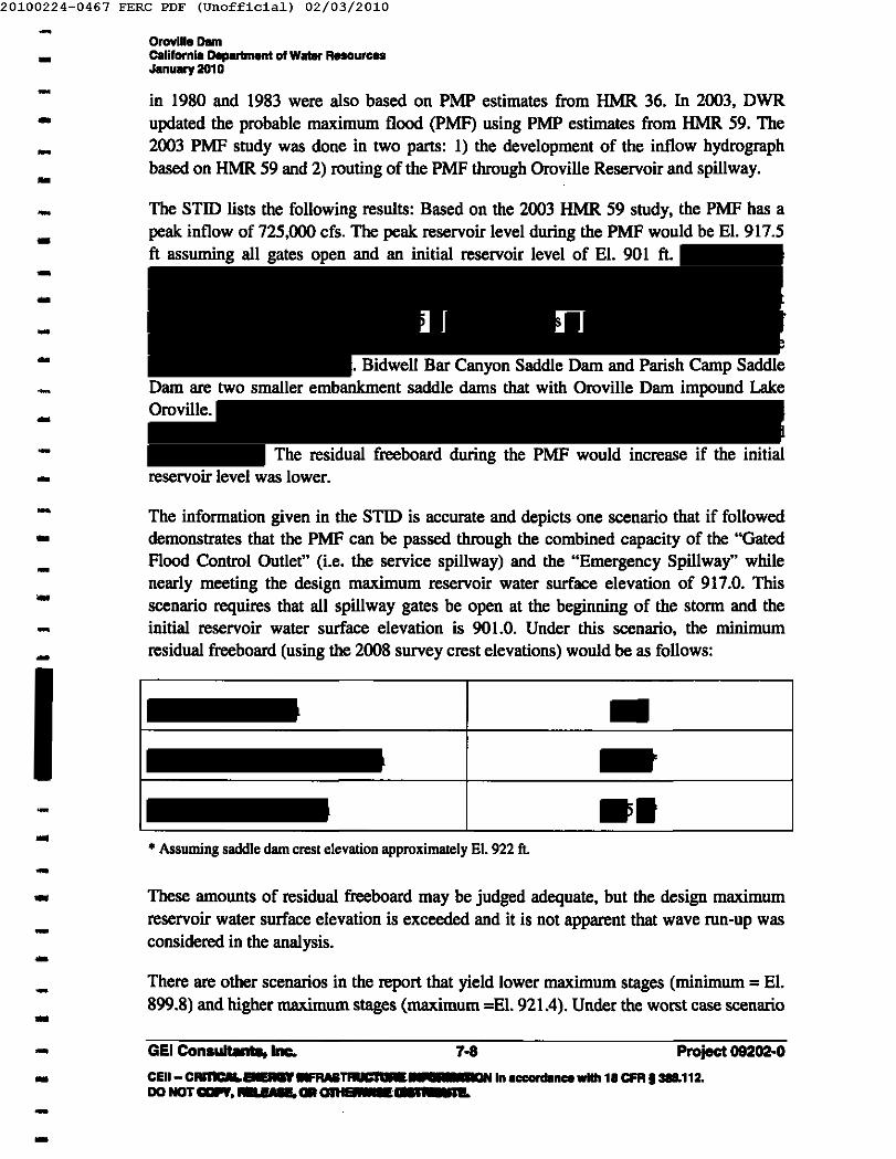
20100224-0467 FERC PDF (Unofficia1) 02/03/2010
-- Oroville Damcalifornia Depertment of WaI8r ResourcesJanuary 201 0
- in 1980 and 1983 were also based on PMP estimates from HMR 36. In 2003, DWRupdated the probable maximum flood (PMF) using PMP estimates from HMR 59. The2003 PMF study was done in two parts: 1) the development of the inflow hydrographbased on HMR 59 and 2) routing of the PMF through Oroville Reservoir and spillway.
---- The STID lists the following results: Based on the 2003 HMR 59 study, the PMF has apeak inflow of 725,000 cfs. The peak reservoir level during the PMF would be El. 917.5ft assuming all gates open and an initial reservoir level of El. 901ft.
. Bidwell Bar Canyon Saddle Dam and Parish Camp SaddleDam are two smaller embankment saddle dams that with Oroville Dam impound LakeOroville.
The residual freeboard during the PMF would increase if the initialreservoir level was lower.
---------- The information given in the STID is accurate and depicts one scenario that if followeddemonstrates that the PMF can be passed through the combined capacity of the "GatedFlood Control Outlet" (i.e. the service spillway) and the "Emergency Spillway" whilenearly meeting the design maximum reservoir water surface elevation of 917.0. Thisscenario requires that all spillway gates be open at the beginning of the storm and theinitial reservoir water surface elevation is 901.0. Under this scenario, the minimumresidual freeboard (using the 2008 survey crest elevations) would be as follows:
--..--
-..• Assuming saddle dam crest elevation approximately EI. 922 ft.-
-These amounts of residual freeboard may be judged adequate, but the design maximumreservoir water surface elevation is exceeded and it is not apparent that wave run-up wasconsidered in the analysis.
--- There are other scenarios in the report that yield lower maximum stages (minimum = El.
899.8) and higher maximum stages (maximum =El. 921.4). Under the worst case scenario-GEl Consllltalao Inc. 7-8 Project 09202-0-- CEII- CIUftCII.. sa -.ul&TRIICIWaaa DNIn accarclence willi 18 CFR ,-'112.DONOTa.f,_s'. Giant. J ... , n.--
20100224-0467 FERC PDF (Unofficia1) 02/03/2010
.. OrovUleDamCIIllfornla Department of Water R.... urcesJanuory 2010
- it is likely that the residual freeboard would be found inadequate if wave run-up wereaccounted for.
--
Part of the difficulty in assessing the adequacy of the spiIIway(s) is that the analysis iscontained in two separate reports and the reports lack certain detail such as: rainfall/snowdistribution, loss rates, graphics, and HEC software output. Perhaps most importantlythere is no articulated reservoir operation plan or scenario. The overall result is that thereader must draw their own conclusions based on the presented range of results, not fromthe analyst's stated findings and conclusions.
-...
--
In view of the available information it is the Independent Consultants' expectation thatthere is adequate spiIIway capacity to pass the design PMF, however, that conclusioncould not be clearly drawn from the existing reports. To present this information moreclearly the Independent Consultants recommend the following:
-..-
• Prepare a single report for assessing the adequacy of the OroviIIe Dam spiIIway(s)with respect to passing the PMF.
- • Detail all assumptions and input detail such as: rainfall and snow depth durationand distribution, loss rates, hydrologic model, etc. and intended operatingscenario(s) including: starting water surface elevation, gate operation plan, etc.The design scenario(s) should conform to operation plans and agreements bothinternal and external to DWR.-
-• Include typical spiIIway evaluation criteria such as starting water surface
elevation at certified maximum reservoir level, gate operation plan, outlet valveoperation plan, powerplant operation plan, wave run-up, etc.
-The completion of this analysis and report wiII clearly document the spiIIway adequacyand serve as a reference for how the complex wiII be operated under extreme hydrologicconditions.
-- 7.6.2 Spillway Structure - Concrete Assessment
-Periodically, a thorough assessment is conducted on the spiIIway to serve as a basis forconcrete repair work. In April 2008, personnel from DWR's O&M headquarters andOroville Field Division inspected the concrete surfaces of the spillway. The spillway wasevaluated visually for cracks, erosive wear and spalling and by sounding using draggedchains and hammers for incipient spalls and voids. Overall, the condition of the spillwaywas found to be good. At the time of our inspection, DWR was in the process of markingareas to be patched and intended to complete spillway repairs. DWR indicates that therepairs were completed in December 2009.
-----
GEl Consultants, Inc. 7-9 Project 09202-0-- CElI- CRITICAL ENERGY INFRASTRUCTURE INFORMATION In _nca with 18 CFR, 388.112.DO NOT COPY, RELEASE, OR OTHERWISE DISTRIBUTE.--
20100224-0467 FERC PDF (Unofficia1) 02/03/2010
-- OrovllleOemcallfomla Oepartment 01Water RllllourcesJanuary 2010
- 7.7 Surveillance and Monitoring Program-.•
Section 7 of the STID describes the project instrumentation program at Oroville Dam.DWR has prepared a DSSMP in accordance with FERC's DSSMPIDSSMR guidelinesdated January 15, 2008, Rev. 2. The DSSMP was submitted to FERC in December 2008and the DSSMP is included as Section 7 of the STID. See Section 4 herein for a detailedassessment of the current instrumentation and performance monitoring at Oroville Dam.
---- 7.8 Stability and Stress Analyses of Project Structures-- 7.B.1 Existing Stability Analys;s-- Section 8 of the STID describes the stability studies performed to date for Oroville Dam.
Oroville Dam has been analyzed in the past for static and seismic loading conditions. Aseismic reanalysis was conducted in response to the 1975 Oroville earthquake. Amagnitude 6.5 earthquake at a hypocentral distance of 5 kilometers producing amaximum ground acceleration of O.6gat the base of the dam was considered.
---- In the 1999 Part l2D Safety Report, the Independent Consultants recommended that athorough and updated stability analysis be performed for Oroville Dam, Bidwell BarCanyon Saddle Dam, and Parish Camp Saddle Dam. In 2005, DWR Division ofEngineering (DOE) completed the recommended reanalyses. The updated stabilityevaluation included Oroville Dam, reviewing both upstream and downstream slopes, aswell as both Bidwell Bar Canyon and Parish Camp Saddle Dams.
----
-
The engineering properties of the embankment materials used for the original design ofOroville Dam were assumed for the 2005 analyses. Studies performed since the originaldesign have reviewed actual rockfill strengths in relation to grain size, testing apparatus,void ratio, and material type (including Oroville rock fill). The results of these studiesshowed that the original design values are conservative. For the core (Zone 1), a bilinearstrength envelope was used for rapid drawdown conditions. This rationale for using thebilinear envelope was that pore pressures in the core may not have time to reachequilibrium with reservoir levels due to the relatively rapid changes in the reservoirlevels. The bilinear envelope combines the minimum of both effective stress and totalstress envelopes.
-------
Both steady-state seepage and simplified seismic stability analyses were conducted toevaluate embankment stability. The steady-state seepage stability of the maximumembankment section was evaluated using the computer program SlopeJW. Factors ofsafety exceeding minimum criteria were computed for all loading conditions consideredand therefore the embankment section was judged to be stable.
----
Project 09202-0CEII- CRITICAL EIIERCD'~ INFORMATION In ..... 1ac:FR 1388.112.00 NOTc:opo" - 5 7 ClRona: I... " STE.
- GEl Consultants, Inc. 7-10---
20100224-0467 FERC PDF (Unofficia1) 02/03/2010-- Oroville Damcalifornia Deptlrlment 01 Waler R.... urcesJanuary 2010- For the seismic analysis, a MCE with magnitude 6.5 was assumed and the PGA wasestimated using current (at the time of the study) attenuation relationships. Assuming a6.5 magnitude at a distance of 3.0 miles and strike-slip motion for a soft rock site, thecalculation resulted in a median PGA of 0.41g and an 84th percentile PGA of 0.67g. The84th percentile PGA of 0.67g is very close to the 0.6g used in the 1976 analysis, but wasbelieved to be too conservative. However, the median value (0.41g) is about two-thirdsthe value used in past evaluations. For the 2005 study, the analyses assumed 0.6g to beconsistent with past work.
-------
Earthquake displacements were estimated using the Makdisi-Seed simplified procedures.Undrained shear strength parameters for the core material were used in the analysis.Potential upstream and downstream sliding surfaces extending through one-third, two-third, or the full embankment heights were analyzed for both full and partial poolconditions. Relatively small embankment deformations (less than or up to one foot) wereestimated using the simplified seismic stability method. These small deformations areconsistent with the deformations predicted using more sophisticated analyses from the1976seismic analysis (documented in Reference 9).
------
Static and seismic stability analyses were also performed to verify the stability of bothBidwell Bar Canyon and Parish Camp Saddle Dam embankment sections using the sameprocedure and methods discussed for Oroville Dam. The predicted earthquake-induceddisplacements resulting from a magnitude 6.5 event on the Cleveland Hill Fault, withpeak ground acceleration of 0.6g were calculated for the saddle darns. All predicteddisplacements were less than I foot.
----
-The results of the 2005 reanalysis show Oroville Dam, Bidwell Bar Canyon Saddle Dam,and Parish Camp Saddle Dam exceeded minimum factor-of-safety criteria under steady-state seepage conditions. Additionally, simplified seismic stability methods identifiedearthquake-induced displacements of less than a foot when the dams are subjected to themaximum credible earthquake.
---- 7.8.2 Adequacy of Existing Stability Analyses
-As stated in the previous section, embankment stability analyses for Oroville Dam havebeen completed twice, 1979 and 2005, since the original analyses and dam design werecompleted in the 1960's. Also of significance to note is the paper "Earthquake ResistantDesign of Oroville Dam", 1967 ICOLD Proceedings, by Areview of this work demonstrates that appropriate attention has been given to the stabilityof this major dam, particularly the seismic stability, since even before it was constructedover 40 years ago. A review of this body of work reveals that in anticipation of seismicloading and the uncertainty that surrounded structural seismic response of earthembankment darns, the designers provided for a very densely placed earthfill
------
GEl Consultants, Inc. 7-11 Project 09202-0-- CElI- CRrneAL ENERGYINFRASTRUCI'IR b b5 '1'ION In eccanllnca ...... '&CfR'... 112.DO NOT COPY, RELEASE, OR 0111.5 '*5 ....--
20100224-0467 FERC PDF (Unofficia1) 02/03/2010-- Oroville DImcalHarnl. Department of Water RaaourceaJanuary 2010- embankment which they postulated would not weaken under anticipated seismic loading.The good performance of the dam during the 1975 Oroville Earthquake supports theprinciples they used in the original design. Both the original seismic stability design andthe 1979 reanalysis methodologies exceeded state-of-practice approaches at the time theywere performed. There have however, been many advances in seismology, earthquakeengineering, and technology in the years since that work was completed and the purposeof this section is to question whether updated stability analyses are warranted .
----..- 7.8.2.1 Steady-state Seepage Stability-- Steady-state seepage, sometimes referred to as static stability analyses have been
performed at least three times in the past: 1960' s, 1979, and 2005. Minimum factors ofsafety for steady-state seepage loading were exceeded in each of those studies.--
-The recently completed 2005 analysis incorporated the most current approaches andtechnology, so this work can be considered completely up to date. Further in support offinding the dam stable under steady-state conditions, the dam has performed well,showing no sign of instability over the more than 40 year life of the structure.
--- Based on the existing analyses on record and the good past performance of the
embankment it can be concluded that the dam is satisfactory with respect to steady-stateseepage stability.
- 7.8.2.2 SeIsmic Stability
-- The seismic stability of the embankment is likely satisfactory for the following reasons:
- • The dam was originally very well designed and constructed with respect toseismic stability.
- • Past state-of -practice analyses have found the dam adequate with respect toseismic stability.
• The dam performed well in 1975 when subjected to seismic loading.-- • Recent simplified analyses found the dam adequate with respect to seismicstability.-- For most dams, the work and conclusions above would be enough to render a finding of
safety and no further work required. For this dam, however, due to its unprecedented sizeand hazard, changes in seismologic knowledge. improved understanding of soil structure---- GEl Consultants, Inc. 7-12- Pnaiect 09202-0CEII- CRITICAL ENERGY ..... TRIICfta INFORIIATION In MII •• CIIIII-.n&.DONOT COPY, RBF'M _GIIIUF .......um.--
20100224-0467 FERC PDF (Unofficia1) 02/03/2010-... OrovIlle Damcalifornia ll8perlmenl 01Weier Reeou.....January 2010- response and advances in technology, a more comprehensive review of the adequacy ofexisting seismic stability analyses should be considered for the following reasons:--- e Design site seismicity has changed, including understanding of fault sources, their
energy potential and attenuation relationships.-... • Methodologies for determining soil strength under seismic loading has changed.
- • Analytical techniques for calculating seismic deformation have changed. Non-linear analyses are currently more frequently used than linear elastic models.-- • A wide range of deformations have been calculated in the past. The best estimatefrom the 1979 study was on the order of a few feet, but the worst case scenariowas on the order of tens of feet.
..-- • The 200S simplified analysis predicted deformations of less than I-foot, however
this approach should probably be considered oversimplified for a dam of this sizeand hazard.-..
-In view of new knowledge and advances in technology and the state of practice, it islikely a better assessment could be made of potential embankment deformations underseismic loading. Consequently, the Independent Consultants recommend a thoroughreview of the analyses on record, considering the factors above and possibly others, todetermine whether the existing studies remain valid in view of modern practices. Basedon this review, the need for updated seismic stability analyses should be determined.
..-.. Only limited information is available on the details of the analyses for the concrete
structures. According to Section 8 of the STID, the available information regardingseismic and static analyses of the concrete structures indicates acceptable factor of safetyfor sliding stability, overturning and acceptable stresses.
-..-- 7.9 Spillway Gates
- The dam's Flood Control Outlet which is located on the right abutment consists of areinforced concrete headworks structure containing eight top-sealing radial gate bays.-- 7.9.1 Stress Analysis-- DWR performed a structural reevaluation of the spillway radial gates in 1999. Thestructural analyses are fully documented in Section 9 of the STID.The following load conditions were evaluated:
..-- Case I: Closed gate, maximum normal water surface: DL+ Hydrostatic Pressure
- GEl Consultants. Inc. 7·13 Project 09202-0... CEII- CRITICAL ENERGY INFRASTRUCTURE INFORMATION In __ with 1aCRII-'ftI.DO NOT COPY, RELEASE, OR OTHERWISE DISTRIBUTE.-..
20100224-0467 FERC PDF (Unofficia1) 02/03/2010-- Oroville DamCalifornia !lepIIr1menl 01W_ RlIIIOu.....January 201 0- Case 2: Gate starting to open, maximum normal water surface: DL+ Hydostatic
Pressure +Lifting Load+ Trunion Friction (0.30)-- Case 3: Closed gate, maximum normal water surface, seismic: DL+ HydrostaticPressure+Seismic--
-----
The loading conditions used in the 1999 stress analysis are applicable for the radial gatestructure. However, the 1999 structural reevaluation analyzes the gate structure under themaximum normal water surface which is El. 900 ft.
This maximum water surface elevation may bethe 2003 PMF of El. 917.5 ft. Therefore, it is recommended that PMF loading conditionsbe evaluated as follows:
..------- Case A: Closed gate, Probable Maximum Flood Elevation (El. 917.5 ft, 2003
PMF): DL +PMF- Case B: Gate starting to open, Probable Maximum Aood Elevation (El. 917.5 ft,2003 PMF): DL+ PMF +Lifting Load+ Trunion Friction (0.30)-...
-DWR's stress analysis of the gates indicates that seismic loading was considered.Typically, seismic loads are applied in the lateral or horizontal direction. However, it iscommon to consider both a horizontal and vertical seismic loading for critical structuressuch as this in regions that may be subject to vertical as well as horizontal accelerations.It is recommended that DWR consider this in future stress analyses.
---- DWR's stress analysis in Section 9 does not provide any information on the anchorage
analysis. It is important to provide the results of the anchorage analysis.-- 7.9.2 Radial Gate Testing-- The spillway gates at Oroville Dam are operationally tested annually and full open testedevery five years. Results of the most recent annual gate operation tests (full-opening)-GEl Consultanta, Inc. 7-14 Project 09202-0-- CElI- CRITICALENERGYINFRASTR~ INFOIlllATIONIn_nee with 1. ~ __ 1Z.ao.arcaor,RELEASE,OROTHE ' m.--
20100224-0467 FERC PDF (Unofficia1) 02/03/2010
• Oroville DamC.ollfornla Department 01 Water R.... ur ....January 2010.-- performed in April and November 2009 are presented in Appendix G. The spillway gateoperation certificate includes the testing of the gate hoists motors' line-to-line voltage andamperage draw measurements .
.•
.-.•
..
.-..
...
,-The radial gate hoists are tested on a monthlybasis. The frequency and extent of testing appears acceptable. The
mechanical integrity should also be inspected periodically.-- 7.9.3 Structural Inspections and Evaluation
- DWR conducted a structural inspection of the spillway gates in 1997 and severalrecommendations were made. The conclusions and recommendations provide very goodmaintenance and future inspection practices. Section 9 of the STID does not indicatewhether DWR acted on these recommendations or what actions were taken. A follow-upof these recommendations should be investigated and actions scheduled, if necessary.
----
It has been over 10 years since the last structural inspection of the spillway gates wasperformed. DWR should establish a regular plan and schedule for periodic inspection andevaluation of the radial gates (including the trunnion pins). Refer to FERC letter datedDecember 18, 2009 (Ref. 71), for FERC requirements.
--
--GEl Consultanta,lnc. 7-15- Praiect 09202-0CEII-CIU11ClLENERGYtNFRAS~~fa "CRt.=zn.1I01IGTCDPt, RELEASE,OROTHE_ ..........---
20100224-0467 FERC PDF (Unofficia1) 02/03/2010-- Oroville DamC.IHornia Dep..-nt 01 W_ R.... urcesJanuary 2010-
-------- 7.10 Pertinent Correspondence Related to Safety of ProjectWorks-
- Section 10 of the STID contains correspondence with the FERC and the DSOD related todam safety issues. Section 10 should be updated to include correspondence with FERCand DSOD since the 2005 Part 120 Report and the most recent FERC annual inspectionreport.
---- 7.11 Status of Studies in Process and Outstanding Issues
- To our knowledge, there are several on-going safety related studies or outstanding issuesat Oroville Dam.-
- •
-----
•---- •---- GEl Consultants, Inc. 7·16 Project 09202-0- CEII- CIIIIIC& • U INFRASTRUCTURE INFORMATION In--'-wIIh 18 CFR 13811.112.
lID ........ ; _. OR OTHERWISE DISTRIBUTE.--
20100224-0467 FERC PDF (Unofficia1) 02/03/2010
-- Oroville DamClIllfornla IlaparmMnI 01W_ ReaourceaJanuary 2010
•
---- • DWR is developing a plan to inspect the penstocks. including the vertical sections.with an ROV submersible or other remote viewing technique within the next 3 to 5years.--
-•--
-7.12 References-- A list of pertinent project references is included in Section 11 of STID. Since the STIDwas initially drafted. several additional documents relating to Oroville Dam have beenprepared. These reports are listed in the Reference List herein as References 58 to 11.Section 11 of the STID should be revised to include these documents.
-- 7.13 Conclusions--
The Supporting Technical Information Document for the Oroville Dam provides anadequate summary of the available background information on the dam and relatedproject facilities. Based on our review. we recommend the following further studies beperformed:
--- 1. An assessment and update of the instrumentation system and program especially
with respect to long-term monitoring of the phreatic surface within theembankment.
---- 2. The evaluation of the adequacy of the spillway to pass the design flood event(PMF) should be presented in a single volume report considering the commentsmade in Section 1.6.I.See Section 1.6 for further details.---
GEl CO....atants. Inc. 7-17 Project 09202-0-- CB-~ INFRASTRUCTUREINFORIlAnON In ~nce_18 CFR1388.112.IID... CDPf. - 5.,. OROTHERWISEDISTRIBUTE.--
20100224-0467 FERC PDF (Unofficia1) 02/03/2010- Oroville DamcalHa.nla Department 01 Water R.... u .....January 201 0-- 3. A comprehensive review of the stability analyses on record, considering the
factors listed in Section 7.8, to determine whether the existing studies remainvalid in view of modem practices. Based on this review, the need for updatedseismic stability analyses should be determined.
---- 4. We recommend structural evaluation of the spillway radial gates for PMF loadingconditions for two scenarios indicated in Section 7.9.-- We also suggest the following updates to the STID:-- • The 2009 PFMA supplement should be inserted into Section 1 of the STID for
documentation purposes.-- • Further description of the penstocks, turbines,and spillway radial gates should be included in Section 2. Also, we suggest thatdrawings of the penstocks, Hyatt Powerhouse layout,
be added to the figures in Section 2.--- • The construction chronology in Section 3.7 of the STID should be updated to include
project-safety related events and/or repairs since the last Part 12D safety inspectionreport (as listed in Section 2.4 of this report).
--- •-- • Section 5 of the STID should be updated to include a summary of the 1975 Oroville
earthquakes and impacts on the Oroville-Thermalito complex (see Section 7.5).--
• Section 5 of the STID should be updated pending the results of recommended seismichazard assessments (see Section 7.5).
---
• Section 5 of the STID should be updated with the correct location of the constructionspoil placed upstream from the spillway chute.
- • The location of several instruments ( , the toe drainweir, the drainholes, and House T) are not shown in plan in the DSSMP (Section 7 ofthe STID) or 2008 DSSMR (Ref. 69). We recommend that location figures bedeveloped for these documents.
----
• According to DWR, the survey monuments on the Bidwell Bar Canyon and ParishCamp Saddle Dams are offset on the downstream shoulders of the crest roads andtherefore readings do not reflect the dam crest elevations. This is not indicated in the
--
GEl Consultants, Inc. 7-18 Project 092Q2.0-- CEII- CRrnCAL ENERGY INFIlASTRUCTURE INFORMATION In ---.ce with 1. CFR 1-..nLDO NOT COPY, RELEASE, OR OTHERWISE DlSlIIBUJtI.--
20100224-0467 FERC PDF (Unofficia1) 02/03/2010
- OrovIlle DamCllllfornil Dapllrlmlnt of Water R_ourctlllJanuary 2010--
-monument location drawings (Figures 1.7 and 1.8 in Appendix D) or mentioned inthe DSSMP. We recommend that the DSSMP (STID Section 7) be updated to includethis information and a procedure developed to convert and compare of the surveyedmonument elevation data to the design dam crest elevations.
--- • The DSSMP (Section 7 of the STID) should be revised to include the procedures for
taking the instrumentation readings ...- •-- • Section 9 of the STID should be revised to include the status of the recommendations
from the 1997structural inspection of the spillway gates.-- • Section 10 should be updated to include correspondence with FERC and DSOD sincethe 2005 Part 120 Report and the most recent FERC annual inspection report.--- • Section 11 of the STID should be revised to include new documents relating toOroville Dam prepared since the STID was initially drafted (References 58 to 71).----
----------••-
GEl Con.dtants, Inc. 7-19 Project 09202-0-- CEII- CIII'C- ·.RASTRUCTURE INFORIlAnoN In ....... ""' ..... wIth 18 CFR 138L112.DO NOTCXIP9. - • ... OTHERWISEDISTRIBUTE.--
20100224-0467 FERC PDF (Unofficia1) 02/03/2010
- OrovIlle DamCalHa.nla Deparlment 01 Water R.. ourcesJanuary 2010--- LIST OF FIGURES--- See Appendix C for list of figures included in this report.- (Please see Section 2 of the STID for additional drawings.)------------
-------------GEl Consultants, Inc.-- CEII- CRITICAL ENERGY INFRASTRUCTURE INFORMATION In _nlan...wiIIa 18 Cf8t-......00 NOT COPY, RELEASE, OR OTHERWISE DISTRIBUTE.--
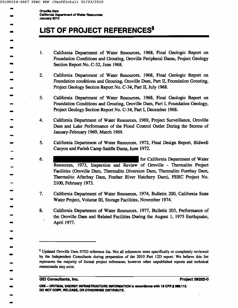
..20100224-0467 FERC PDF (Unofficia1) 02/03/2010
-..-Oroville DamClIllfornla Daparlment 01W_ R.... urceaJanuary 2010
-LIST OF PROJECT REFERENCES§
---..------..-----..-----
1. California Department of Water Resources, 1968, Final Geologic Report onFoundation Conditions and Grouting, Oroville Peripheral Darns, Project GeologySection Report No. C-32, June 1968.
2. California Department of Water Resources, 1968, Final Geologic Report onFoundation conditions and Grouting, Oroville Dam, Part II, Foundation Grouting,Project Geology Section Report No. C-34, Part II, July 1968.
3. California Department of Water Resources, 1968, Final Geologic Report onFoundation Conditions and Grouting, Oroville Darn, Part I, Foundation Geology,Project Geology Section Report No. C-34, Part I, December 1968.
4. California Department of Water Resources, 1969, Project Surveillance, OrovilleDarn and Lake Performance of the Flood Control Outlet During the Storms ofJanuary-February 1969, March 1969.
5. California Department of Water Resources, 1972, Final Design Report, BidwellCanyon and Parish Carnp Saddle Dams, June 1972.
6. for California Department of WaterResources, 1973, Inspection and Review of Oroville - Thermalito ProjectFacilities (Oroville Darn, Thermalito Diversion Darn, Thermalito Forebay Darn,Thermalito Afterbay Dam, Feather River Hatchery Darn), FERC Project No.2100, February 1973.
7. California Department of Water Resources, 1974, Bulletin 200, California StateWater Project, Volume m, Storage Facilities, November 1974.
8. California Department of Water Resources, 1977, Bulletin 203, Performance ofthe Oroville Darn and Related Facilities During the August I, 1975 Earthquake,April 1977.
--..-I Updated Oroville Dam STID reference list. Not all references were specifically or completely reviewedby the Independent Consultants during preparation of the 2010 Part 12D report. We believe this listrepresents tbe majority of formal project references; however other unpublished reports and technicalmemoranda may exist.
- Project 09202-0-..-
GEl Consultants, Inc.CEII- CRITICAL ENERGY INFRASTRUCTURE INFORMATION In _"nee wHh 18 CFR t 388.112.DO NOT COf¥, RELEASE, OR OTHERWISE DISTRIBUTE •
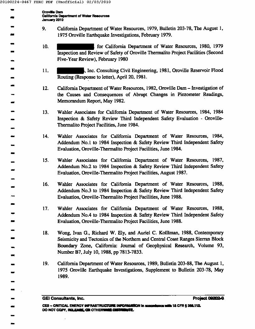
20100224-0467 FERC PDF (Unofficia1) 02/03/2010..Orovili. DamCalifornia Daparlment of Water R",""urcesJanuary 2010-- 9. California Department of Water Resources, 1979, Bulletin 203-78, The August I,
1975 Oroville Earthquake Investigations, February 1979.--- 10. for California Department of Water Resources, 1980, 1979Inspection and Review of Safety of Oroville Thermalito Project Facilities (SecondFive-Year Review), February 1980--
-
1l. , Inc. Consulting Civil Engineering, 1981, Oroville Reservoir FloodRouting (Response to letter), April 20, 1981.
12. California Department of Water Resources, 1982, Oroville Dam - Investigation ofthe Causes and Consequences of Abrupt Changes in Piezometer Readings,Memorandum Report, May 1982.
--- 13. Wahler Associates for California Department of Water Resources, 1984, 1984
Inspection & Safety Review Third Independent Safety Evaluation - Oroville-Thermalito Project Facilities, June 1984.--
-14. Wahler Associates for California Department of Water Resources, 1984,
Addendum No.1 to 1984 Inspection & Safety Review Third Independent SafetyEvaluation, Oroville-Thermalito Project Facilities, June 1984.
--- 15. Wahler Associates for California Department of Water Resources, 1987,
Addendum No.2 to 1984 Inspection & Safety Review Third Independent SafetyEvaluation, Oroville- Thermalito Project Facilities, August 1987.--- 16. Wahler Associates for California Department of Water Resources, 1988,Addendum No.3 to 1984 Inspection & Safety Review Third Independent SafetyEvaluation, Oroville- Thermalito Project Facilities, June 1988.-- 17. Wahler Associates for California Department of Water Resources, 1988,Addendum No.4 to 1984 Inspection & Safety Review Third Independent SafetyEvaluation, Oroville-Thermalito Project Facilities, June 1988.--
-18. Wong, Ivan G., Richard W. Ely, and Auriel C. Kolllman, 1988, Contemporary
Seismicity and Tectonics of the Northern and Central Coast Ranges Sierran BlockBoundary Zone, California: Journal of Geophysical Research, Volume 93,NumberB7, July 10, 1988, pp 7813-7833.
--- 19. California Department of Water Resources, 1989, Bulletin 203-88, The August I,
1975 Oroville Earthquake Investigations, Supplement to Bulletin 203-78, May1989.
..--- GEl Consultants, Inc. Projec:t CP p.o.
CElI- CRmCAL ENERGY INFRASTRuc:nJIIE INFIORIIAImN In __ , n.-.- _18 CFR §3811.112.DO NOTCOPY," 5" 'CIIOTHE....... ' n---
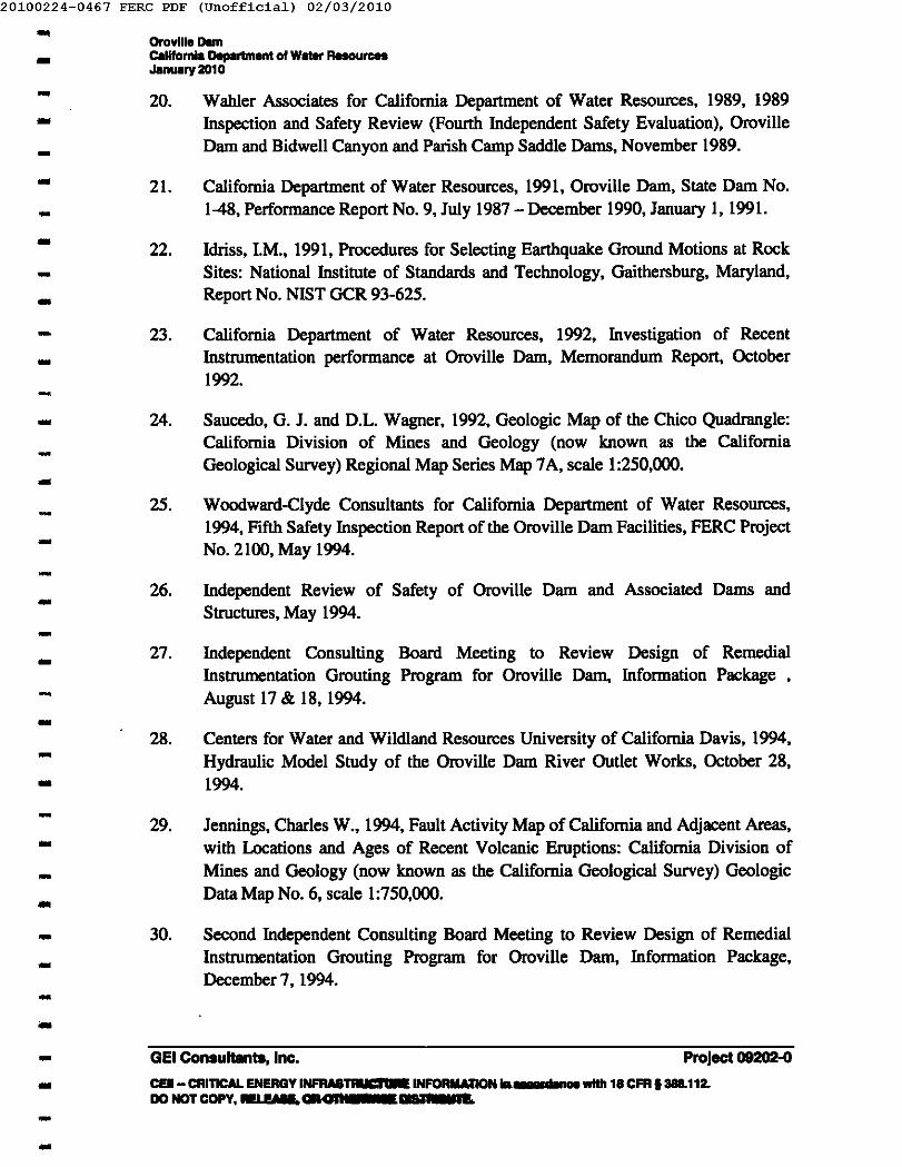
...20100224-0467 FERC PDF (Unofficia1) 02/03/2010
- Oraville OemCollfornia Department 01 W_ ResourcesJanuary 201 0-- 20. Wahler Associates for California Department of Water Resources, 1989, 1989
Inspection and Safety Review (Fourth Independent Safety Evaluation), OrovilleDam and Bidwell Canyon and Parish Camp Saddle Dams, November 1989.--.. 21. California Department of Water Resources, 1991, Oroville Dam, State Dam No.1-48, Performance Report No.9, July 1987 - December 1990, January I, 1991.-- 22. Idriss, 1M., 1991, Procedures for Selecting Earthquake Ground Motions at RockSites: National Institute of Standards and Technology, Gaithersburg, Maryland,Report No. NIST OCR 93-625.-
- 23. California Department of Water Resources, 1992, Investigation of RecentInstrumentation performance at Oroville Dam, Memorandum Report, October1992.
--- 24.
--25.
-26.--- 27.
-- 28.--- 29.---- 30.
---
Saucedo, G. J. and D.L. Wagner, 1992, Geologic Map of the Chico Quadrangle:Califomia Division of Mines and Geology (now known as the CaliforniaGeological Survey) Regional Map Series Map 7A, scale 1:250,000.
Woodward-Clyde Consultants for California Department of Water Resources,1994, Fifth Safety Inspection Report of the Oroville Dam Facilities, FERC ProjectNo. 2100, May 1994.
Independent Review of Safety of Oroville Dam and Associated Dams andStructures, May 1994.
Independent Consulting Board Meeting to Review Design of RemedialInstrumentation Grouting Program for Oroville Dam, Information Package ,August 17 & 18, 1994.
Centers for Water and Wildland Resources University of California Davis, 1994,Hydraulic Model Study of the Oroville Dam River Outlet Works, October 28,1994.
Jennings, Charles W., 1994, Fault Activity Map of California and Adjacent Areas,with Locations and Ages of Recent Volcanic Eruptions: California Division ofMines and Geology (now known as the California Geological Survey) GeologicData Map No.6, scale 1:750,000.
Second Independent Consulting Board Meeting to Review Design of RemedialInstrumentation Grouting Program for Oroville Dam, Information Package,December 7, 1994.
- Project 09202-0- GEl Consultants, Inc.CElI- CRITICAL ENERGY INFIIAII~ INFORIIATION __ .. 1.... n,... _ 18 CFR 1388.112.DONOTCOPY,-IE'. GROft'Sd_.dl 1m.--
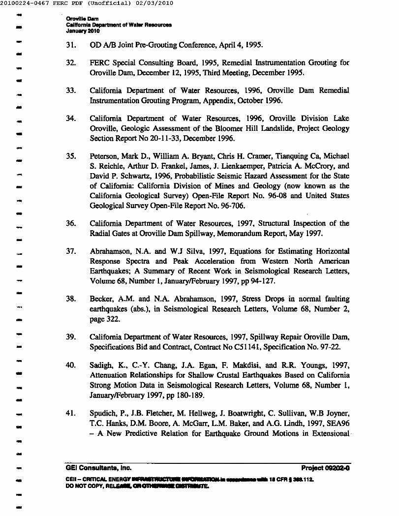
-20100224-0467 FERC PDF (Unofficia1) 02/03/2010
- Oroville Damcalifornia Department 01 W ..... R...... r...January 2010- 31.- 32.-- 33.
...- 34.-- 35.----- 36.
-37.--- 38.
-- 39.-- 40.--- 41...-...
OD AlB Joint Pre-Grouting Conference, April 4, 1995.
FERC Special Consulting Board, 1995, Remedial Instrumentation Grouting forOroville Dam, December 12, 1995, Third Meeting, December 1995.
California Department of Water Resources, 1996, Oroville Dam RemedialInstrumentation Grouting Program, Appendix, October 1996 .
California Department of Water Resources, 1996, Oroville Division LakeOroville, Geologic Assessment of the Bloomer Hill Landslide, Project GeologySection Report No 20-11-33, December 1996.
Peterson, Mark D., William A. Bryant, Chris H. Cramer, Tianquing Ca, MichaelS. Reichle, Arthur D. Frankel, James, J. Lienkaemper, Patricia A. McCrory, andDavid P. Schwartz, 1996, Probabilistic Seismic Hazard Assessment for the Stateof California: California Division of Mines and Geology (now known as theCalifornia Geological Survey) Open-File Report No. 96-08 and United StatesGeological Survey Open-File Report No. 96-706.
California Department of Water Resources, 1997, Structural Inspection of theRadial Gates at Oroville Dam Spillway, Memorandum Report, May 1997.
Abrahamson, N.A. and W.J Silva, 1997, Equations for Estimating HorizontalResponse Spectra and Peak Acceleration from Western North AmericanEarthquakes; A Summary of Recent Work in Seismological Research Letters,Volume 68, Number I, January/February 1997, pp 94-127.
Becker, A.M. and N.A. Abrahamson, 1997, Stress Drops in normal faultingearthquakes (abs.), in Seismological Research Letters, Volume 68, Number 2,page 322.
California Department of Water Resources, 1997, Spillway Repair Oroville Dam,Specifications Bid and Contract, Contract No C51141, Specification No. 97-22.
Sadigh, K., C.-Y. Chang, J.A. Egan, F. Makdisi, and R.R. Youngs, 1997,Attenuation Relationships for Shallow Crustal Earthquakes Based on CaliforniaStrong Motion Data in Seismological Research Letters, Volume 68, Number I,January/February 1997, pp 180-189.
Spudich, P., J.B. Fletcher, M. Hellweg, J. Boatwright, C. Sullivan, W.B Joyner,T.C. Hanks, D.M. Boore, A. McGarr, L.M. Baker, and A.G. Lindh, 1997, SEA96- A New Predictive Relation for Earthquake Ground Motions in Extensional·
-- GEl Consultants, Inc. Project0920Z00CEII- CRmCAL ENERGY .u,uaSIiiiC1_ aua ... _ .... __ 18CFR, 388.11Z.DO NOT COPY, REI F 77 GRGlla, • ....-ne.--
-20100224-0467 FERC PDF (Unofficia1) 02/03/2010
- Oroville DamCalifornia Departm""t of Water R.... urceaJanuary 201 0--- 42.-- 43.-- 44.-
-- 45.--- 46.
-- 47.
--- 48.
-- 49.-- 50.--- 51.--- 52.--
Tectonic Regimes in Seismological Research Letters, Volume 68, Number I,January/February 1997, pp 190-198.
California Department of Water Resources, 1999, Structural Reevaluation of theRadial Gates at Oroville Dam Spillway, February 1999.
Independent Review of Safety of Oroville Dam (Oroville Dam, Therma1itoDiversion, Forebay, Afterbay Dams, Feather River Fish Barrier Dam), May 1999.
Gomez & Sullivan Engineers, P.E., Engineering Inc. for CaliforniaDepartment of Water Resources, 1999, Sixth Part 12 Safety Inspection Report forthe Oroville Dam, Oroville-Thermalito Power-Complex, FERC No. 2100,September 1999.
California Department of Water Resources, 2000, Oroville Dam, PerformanceReport No. 10, January 1991- July 2000, August 2000.
California Department of Water Resources by Tim Kennelly - Chief CorrosionEngineering Services, 2001, Oroville Dam Radial Gate 4 Trunnion PinInspection, November I, 200 1.
Fraser, William A. and Jeffrey K. Howard, 2002, Guidelines for Use of theConsequence-Hazard Matrix and Selection for Ground Motion Parameters:California Department of Water Resources, Division of Safety of Dams, GeologyBranch, October 4, 2002, 9 p.
California Department of Water Resources, 2003, Memorandum of Inspection,Hyatt Powerplant Oroville Dam, March 17,2003.
California Department of Water Resources by and reviewed by2003, Hyatt Pump-Generating Plan Inspection
Report, March 17,2003.
California Department of Water Resources by PE, 2003,Memorandum of Inspection, Hyatt Powerplant OrovilleDam, April 28, 2003.
California Department of Water Resources, 2003, Lake Oroville UpdatedProbable Maximum Flood Memorandum, June 1,2003.
Project 09202-0- GEl Consultants, Inc.- CEII- CRITICAL ENERGY INFRASTRUCIUIIE INFORMATION In IICCO__ 1aCFR ,3&112.lID NOT c.¥, RELEASE, OR OTHE~IIIIRRBUTL--
-20100224-0467 FERC PDF (Unofficia1) 02/03/2010
- Oroville Oemcalifornia Oep.Irtment 01 Water ResourcesJanuary 2010- 53.--- 54.
-- 55.---- 56.
-- 57.-- 58.--- 59...- 60...-- 61.
-- 62.
-- 63.
-- 64.-..- 65.-
California Department of Water Resources, 2003, Investigation of SpillwayRouting During Probable Maximum Rood at Oroville Dam, MemorandumReport, December 2003.
California Department of Water Resources, 2004, Oroville Dam PerformanceReport No. II, August 2000 - June 2004, August 2004.
Page, William D. and Thomas L. Sawyer, 2004, Overview of late CenozoicFaulting in the Sierra Nevada Foothills (Including a Reassessment of Faults NearNew BUllards Bar Dam): Pacific Gas and Electric and Piedmont GeoSciences,Inc., unpublished report, 33 p., 5 tables, 5 figures.
California Department of Water Resources, 2005, Oroville Facilities SlopeStability Analysis, Oroville Dam, Bidwell Bar Canyon Saddle Dam, and ParishCamp Saddle Dam August 2005.
California Department of Water Resources, Division of Operations andMaintenance, Standard Operating Qrder Number PC 700.20.
HDR and Geomatrix, 2005, Oroville Dam, FERC Part 12 Report, Butte County,California, FERC Project No. 2IOO-CA,March 2005.
California Department of Water Resources, 2005, Memorandum Re: Survey ofOroville Dam, Spillway Slide, and Bloomer Slide, dated August 3, 2005.
California Department of Water Resources, 2003, revised 2006, Investigation ofSpillway Routing During Probable Max Rood, Oroville Dam, August 2006.
California Department of Water Resources, Division of Engineering, 2007, DamBreach and Inundation Study, Oroville Dam, September 2007.
California Department of Water Resources, Division of Engineering, 2007, DamBreach and Inundation Study, Bidwell Saddle Dam, September 2007.
California Department of Water Resources, Division of Operations andMaintenance, 2008 Oroville Dam Spillway Inspection & Condition Assessment,March 2008.
California Department of Water Resources, Division of Operations andMaintenance, 2008 Hyatt Power Plant Penstock Inspections, May 2008.
.. GElConsultants,Inc. Project09202-0
CElI- CRrnCAL ENERGYINF~iWI_= U _a._IIIIIt'ncrce:ewllh18CFR 1388.112.IIGIGrCQPY,RELEASE,OR01IIES E...-m.
--..
-20100224-0467 FERC PDF (Unofficia1) 02/03/2010
- OrovilieDemC8IHomla Deportment 01 Water ResourcesJanuary 2010- 66.--- 67.--- 6S.-- 69.-
- 70.--- 71.
------------------
California Department of Water Resources, Division of Engineering, 200S,Bloomer Hill Landslide; Results of Geologic Inspection, Oroville Darn, ProjectGeology Section Memorandum Report No. 20-11-36, dated June 17, 200S.
California Department of Water Resources, Division of Engineering, 200S, DarnBreach and Inundation Study, Parish Carnp Saddle Darn, November 200S.
California Department of Water Resources, 2009, Darn Safety Surveillance andMonitoring Report No. 13, Oroville Darn, June 2009.
California Department of Water Resources, 2009, Supporting TechnicalInformation Document (STID), Oroville Darn, Butte County, California, Oroville-Therrnalito Complex, FERC Project No. 2100-CA, June 2009.
FERC (2009). Letter dated December IS, 2009 Re: Tainter Gate Initiative I DarnOwner Responsibilities.
- Project 09202-0GEl Consultants, Inc.- CEII- CRrneAL ENERGY INFRASTRUCTURE INFORMATION In __ 18 CFR 1388.112-DO NOT COPY, RELEASE, OR OTHERWISE DISTRIBUTE.--
20100224-0467 FERC PDF (Unofficia1) 02/03/2010-- 0nMUe DIIIftCIIllfarnl. Dapartment of W_ R_Durce.Jlnuary 2010-- APPENDIX A--- FERC Letter Requiring Part 120 Inspection
---
Letter dated October 28, 2008
Letter dated May 6, 2009 (granting extension of time)..---------------------- GEl Consultants, Inc. Project 09202-0- CElI- CRITICAL ENERGY INFRASTRUCTURE INFORMATION In I.... ntlne. with 18 CFR 1388.112.
DO NOT COPY, RELEASE, OR OTHERWISE DISTRIBUTE.--
20100224-0467 FERC PDF (Unofficia1) 02/03/2010- APPENDIX A20081103-0120 F.ERC PDF Cuaaff1cl.ll 10/28/2008-- •---------------
FEDERAL ENERGY REGULATORY COMMISSION0fIlce 01 EDelV Projects
.,." ..... .,.,. • ....., .............. -5M JItII 10tIIce901MarblSCnel, s.tIel51l,5M ar ~ ,.103
(415),. DOl DIllIe (415)3" D22haI.1Ie
October 28. 2008
In reply, Mfer to:Project No. 2100-CANATDAM ID Nos. CAOOO]S, ct al.
Mr.Stale Willer Project DepuIy DirectorCalifornia Department of Water R.esoun:esP.O. Box 9428]61416 Ninth StreetSacramento. CA 94236-0001
Re: Independent Consulllnt's Safely Inspection Report
Dear Mr. Torres:-- The Eighth Part 120 Inclepcndent Consultant's five-year safety inspeetion reportsfor your Oroville, Bidwell Bar Saddle, Parish Camp Saddle, 1bermaIito Diversion,Thennalito Forebt.y, Thermalito Afterbay and Fish BIII'rier Dams, FERC Projcc:t No.2100 arc due by July IS,2009. Part 12D of the Commission's Regulations describes thescope of the inspections and evaluatioas to be performed by an independent consultantand the iDfonnalion that must be contained in the report. Potential FailOR ModeAnalysis (PFMA) sessions for the Ibove dams were conducted in the 2004 and 8M notrequired. Thra: copies of each the Part 12D Reports must be sent to this office no laterthan July I S, 2009.
With the 2004 Seventh PId 12D Report, you submitted the Supporting Technic:a1Infonnalion Document (mD). Chapter 14 of the Commission's Eqineering GuideJiaesdermes the S11D II a "living document" and any new data or analyses tIIat have becomeavailable since the previous STID submitIaI should be provided to the current Part 120consultant for review and then submitted to the Commission IS discussed in Cbapter 14.Jfnee lied, the Enaincain& Guidelines can be onJaed &am the Commission's Division ofPublic and JnIcrgovmamental AfI'airs at (202) .502-6011 or downloaded fium thefollowing website:
------------ bttp:liwww·fqc'lOYfmd".m...n.ydrqpowq!yfml&uidelineslena-RUicie 'IP---- CEII- CRITICAL. ENERGY INFRASTRUCTURE INFORMATION in a<:<:or<Iance with 18 CFR §388.112.DO NOT copy, RElEASE, OR OTHERWISE DISTRIBUTE ....
-20100224-0467 FERC PDF (Unofficia1) 02/03/2010
APPENDIX A.. 20081103-0120 !ERe PDF (Unofficial) 10/28/2008
- •----------------------------------
You should review the requirements in Chapter 14 and plan for the update of theSTID between now IIld the lime that it is needed for the Part 12D Inspection.
You must obtain lhc Commission's approval of your ploposed indcpcndcntconsuhlllt prior to lhc initiation of lhc inspcclion. PIcuc note that IIIc:nainccr tiom thesame fum will DOlbe Ipproved IS the indcpcnclent COII5ulllllt for more than twoconscc:utive Part 12D Safety Inspections of Illy project. You should send three copies ofyour letter requesting approval of the consultlllt with his or her detailed raumc! to:
Mr. DirectorDivision of Dam Safety and Inspections (02SI), OEPFec1eraI Energy Regulatory Commission888 Fint Street, N.E., Room 6N-OIWashinatOll, D.C. 20426
One copy ofthc lcucr and mum should also be sent to this offia:. As requiredby our ReguJalions, the request for the approval ofthc independent consultlllt is to befiled allcasl60 days prior 10 the inilialion of the safely inspection. In order to allow yourconsultant adequate time to inspect your projeclllld prepare the report, we request lhalyou submit the request letter and raum~ allcast six moaths befon: the RpOIt is due.
Appendix H ofChaptcr 14 of the Eqinccring Guidelines (copy enclosed) is theoutline that establishes the format to be followed for preparation of the indcpcnclcntconsuItIIlt's safely inspcc:tion report. Stability and SlI'csIS lIlaIyses ofrcprclcntativeSIl'UCturaI sections must be plcpmcd or have previously been pcqwcd uacIer IIIetedibleloading conditions. This infixmalion will be located in the STlD, which you areresponsible for updaling. Acceptable technical criteria are prescribed in Chapter 14.
Section 7 of the Part 120 Report will contain your consultant's assessment of theSTID. The studies that form the basis for bis or her conclusions sbouId be summarized.When your consultlllt's conc:lusions are based on the c:oatcnts ofprcvious reports IIldstudies, be or she must provide a clear and c:omprchcnsive statement of conc:urraJCe ornon-concurreac: with the methodology, assumptions and conclusions oftbose studies.Reasons for non-concunenc:e must be explained and may require an analysis by theconsultant to show the efTcc:ISon factors of safely of the SIIUCtUrcs.
If your consultant makes specific recommendations in the rcpod, Section 12.39 ofthe Commission'. Regulations requires thai· you submit to us. within 60 days ofabe dalethe report is filed. your plan of action and scbedule to satisJY those recommendations.Your plan of action may include any JIIOiO!OSII, including taking no action, thal youconsider I preferable a1tcmalive to any comctivc measures recommended by theconsultant in the report. However, any proposed alternative must be supported bycomplete justirlCalion and detailed analysis. Also, it is your responsibility to ensure lhal
2
CEil - CRmCAL ENERGY INFRASTRUCTURE INFORMATION In acoordance JNiIh 18 CFR §388.112.DO NOT COPY, RELEASE, OR OTHERWISE DISTRIBUTE.
-20100224-0467 FERC PDF (Unofficia1) 02/03/2010
APPENDIX A.. 20081103-0120 PERC PDF (unofficial) 10/28/2008
- • •..-..---..---------...-----..-..-..-..-..--
the independent consultant is informed of any outstllJding recommendations and issuesfiom the previous Part 12 reports.
Your continued wopaation in this aspect ofthc Commission's proanm isappra:iatcd. If you have any questions, please contact at
.
Sincerely,
(ForRegionaJEngineer
Enclosure: Engineering Guidelines (Appendix H. Chapter 14)
3
CEII- CRITICAL ENERGY INFRASTRUCTURE INFORMATION in accordance willl 18 CFR § 388.112.DO NOT COPY. RELEASE. OR OTHERWISE DISllUBUlE.
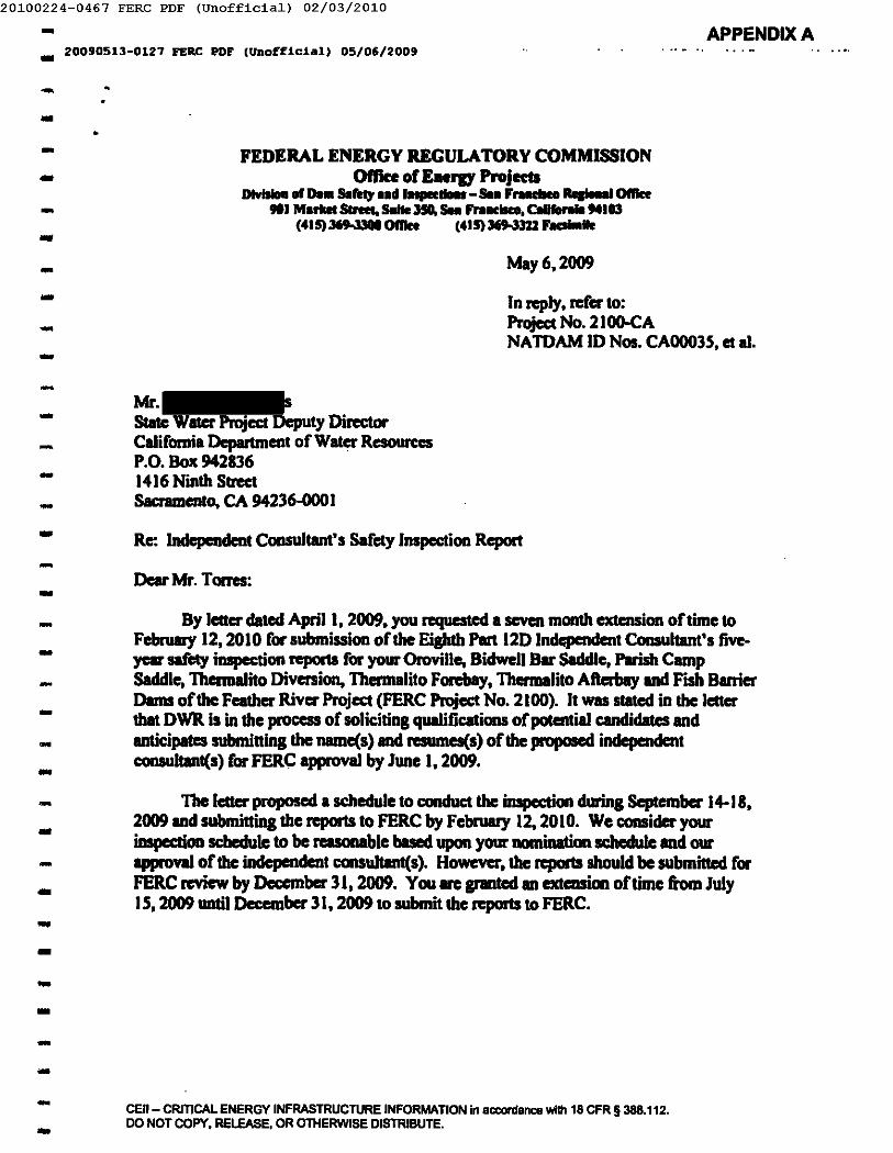
-20100224-0467 FERC PDF (Unofficia1) 02/03/2010
APPENDIX A.. 20090513-0127 FERC PDF (Unofficial) 05/06/2009
-..•-..
---------------------..-..-..-..----
FEDERAL ENERGY REGULATORY COMMISSIONOftke of Eaeru Projects
DlwillD. or De.. s.rea, •• d I -s................. 0IIIce901M.rIIet 51.... s.JIe J5II," 1IC1lco. c.urono .. "103
(415) l69 l3GO0IIIce (415) 369-33U ...-1IeMay 6,2009
In reply. mer to:Project No. 21()()'cANA roAM ID Nos. CAOOO3S. et al.
Mr.State Walcr Project Deputy Dim:torCalifornia Department of Walcr ResourcesP.O. Box 9428361416 Ninth StreetSacramento, CA 94236-000]
Rc: Independent Consultant's Safety Inspection Report
Dear Mr. Torres:
By lectcr dated April I. 2009, you requested a seven month extension of time toFebruary 12, 2010 for submission ofthc Eighth Part 12D Indcpcndcnt Consultant's fIVe-year safety inspection repcx1I for your Oroville, Bidwell Bar Saddle, Parish CampSaddle, Thcrmalito Diversion, Thermalito Forcbay, Thcrmalito Aftcrbay and Fish BarrierDams of the Feather River Project (FERC Project No. 2100). II was stated in the letterthat DWR is in the process of soliciting qualifications of potential candidates andanticipaICs submitting the namc(s) and rcsumcs(s) ofthc proposed independentconsultant(s) for FERC approval by June 1,2009.
The letter proposed a schedule to conduct the inspection during September 14-18,2009 and submitting the reports to FERC by February 12,2010. We consider yourinspcclion schedule to be reasonable based upon your nomination schcdulc IIld ourapproval of the indcpcndcnt consultant(s). However, the reports should be submincd forFERC review by December 31, 2009. You IIIC granted an extaIsion of time from July15,2009 until Dcecmbcr 31, 2009 to submit the reports to FERC.
CEil - CRITICAL ENERGY INFRASTRUCTURE INFORMATION in acconlance willi 18 CFR § 388.112.DO NOT COPY. RELEASE. OR OTHERWISE DISTRIBUTE.
20100224-0467 FERC PDF (Unofficia1) 02/03/2010- APPENDIX A20090513-0127 FERC PDF (Unofficial' 05/06/2009-- •--
-Yourconlinucd c:oopen.liOll in this aspect of the CommissiOll's program is
appn:ciated. If you have any questions, please contact a'(
-- Sincerely.- X-
Regional Engineer
----
cc:Mr.Chief Dam Safety BranchCalifornia Department of Water ResourcesP.O. Box 94211361416 Ninth Street, Room 604·9Sacnmento, CA 94236-0001
----------..------- 2-- CEIl- CRITICAL ENERGY INFRASTRUCTURE 'NFORMATION in accordance wilh 18 CFR § 388.112.
DO NOT COPY. RELEASE. OR OTHERWISE DISTRIBUTE.-
20100224-0467 FERC PDF (Unofficia1) 02/03/2010-- Orovtlle DamC.llfom" Department of Water Resou .....Januery 2010-- APPENDIXB-..
,- FERC Letter Approving Consultant--- Letter dated July 21, 2009
---------------.--------
GEl Consultants, Inc. Project 09202-0- CEII- CRITICAL ENERGY INFRASTRUCTURE INFORMATION In accordance with 18 CFR §388.112.DO NOT COPY, RELEASE, OR OTHERWISE DISTRIBUTE.
-
20100224-0467 FERC PDF (Unofficia1) 02/03/2010
- APPENDIXB.. 20090724-0093 PERC PDF (Unofficial) 07/21/2009
--
FEDERAL ENER.GY REGULATOR.Y COMMISSIONOffice ofEDaJy Projects
Division of Dam Safety aDdlnlpectioaa888 First StnId, ME Rooting Code: PI-13
Wubingtoa, DC 20426(202) 502-6743 Office - (202) 219-2731 FlICIimilc
----- JUL21DB-- III reply refer to: P-21oo--
-
Mr.Chief, H:pchopower u- PIInIIing aDd Compliuc:cExecutiw DivisionStale ofCaliforaia - The R.cIoun:ca ~Dcputmea& ofW ... Reeoun:aI1416 Ninth Street - P.O. Box 942836Saa'ameDto, Califoraia 94236-0001
----
-
Dar Mr. Ramirez:
By letter cIated JUlIO II, 2009, you ptopoaed Mr. P.E.,Mr. P.E., G.E.,1IId Mr. uthe eo-in ...... dcntCCIISUltIDts to be responsible for tile ciahth Part 120 safety illll*tioaI of theDevc10pmeaIs of tile Fcatber Riwr Project lilted on Enc:!oaure A. Mr. 's I11IIIMr. ,.. ..... c:oa6rm that they meet tile Cc.uamiujcm.'s iadepmdeDt CCIIIIUItIIItqualificatio.lpecifaed in Sectioa. 12.31(a) of tile replatiCIIII. Mr. . _ Mr.
are _more ippioved u tile iMepcl"4cot CODSUltaDtI for tIIIIsc iaspectiou. InacccmIIIIcc with Part 12. Subpart D, tile appnwed inMpeDdcDt COIIIIIIIaIlts IIlIISt citberpcrIOIIIIIly inspect tile devcIopmcats or be plCIE during tile iDSpectioIII to mperviJcthose iDdiviclualJ that c:oadw:t tile iDSpecdonI. You are also remby,", to iIIItnIct JOIII'CCIN'IltaDti that Ihould any c:oadition be cIiIcovcIed that requires CIDIiiIBCEY ccarectivcmeuures, dilly must iJnmediately notify you, since you are required to submit a report tothe RqiMd EDaincer in acccadancc with SectiClIl12.36.
--------
Mr. r-une iDdic:ata tbat he Ills ..mmsjw cxpcricDcc inpaloI)'.Howcwr, bia resume does DOt indic:atc tbat he is a rcsiSIaed proCeuional mama IlOl'docs it iDcIicatc tbat be bu 10,.,. of cxpcricDcc in-p,CODJtructioD, _ iDSpoctioDSof clams. AI a result, Mr. is IMIt IIJIIIRMIII u an iIMlepcDcIcnt c:oasuIfIDt. Mr.may, bowcwr, participate with Mr. Mr. in the inspection of tileproject IIIdprepIIlIIion of tile Part 1m reports.
------- CEil - CRITICAL ENERGY INFRASTRUCTURE INFORMATION in accordance with 18 CFR § 388.112.
DO NOT COPY. RELEASE. OR OTHERWISE DISTRIBUTE.-
20100224-0467 FERC PDF (Unofficia1) 02/03/2010
- APPENDIXB_ 20090724-0093 FERC PDF (Unofficial) 07/2V2009
-- -2-
--
'I'bnIe copies of the iDapection IepodIIIlUIt be tiled with the D2SI-San FrnciacoR...., Office by DecIImber 31,2009. Tbe coasuJtant,' repoI1IlIlUIt be t"ormatted illaaxmIancewithBac1011R I, Put 120 Safety lIIspcclioa Report 0utIiDe (nMledJuIy I,2(05). You Ihould ramiDll your c:oDSUltants that it is impcldmt to IIlbmit 1..-that Irercxmllllld in ICCCII'dance with the Outline IIIdwbich adequately Iddrea .u theiDium_lion requesIIId. The irIIpa:tioDI aDd project feaIunIs II1II,- III"C to iDchldc Ithorough evaluaIiOD or.u dam IIf"cly upects or the project illICCClIdaDcc with theCommiIIion', Part 120 Dam Safety RcguJatiCIIII COIIIiIteat with die nIqIIiremaIIBcovered in the CommiIIicm', EDP-inIGuidelines.
------
1.51 pert or addn:IIiDa the iDfcxmllioa requested above. the inc!qMmdeatc:oasuIlIId Ibould specifically review the PFMA for lIlY appropriate c...... illPPMCIIe&OIY c:Jaaific:ation 1bia iDcluda reviftliq all npoN aDd iJMstiptiCIIII pedwmcdor cmaoinIliDcc the prwious Put 120 report aDd cIetoiilininl whether the iat'ormationin tbeIa rcpoItI aDd invesliptiou have c:hIqecIa PFM c:ateaorY claaific:aticm oriDInJcIuced any additicma1 PFMa. Tbe igdqlendeat coasulllld should also address tholeitellll ipOCific to tbe project tbat were iDcludecl in the Part 12D remiader 1cUcr seat to JOUby the Kepoaal Offic:c.
-----
The rust Part 120 IHfepalllcDt ConIulIaDt IaspectiCIIII for IICWCOIIIInIctedprojectl or projects whare IlIIIjar dam ..r.ty """""illion bas receotly beCB C!OIIIpIeted1liiYbe dcmD by the dpip enair-r" ar ID enainer &om the desip CDI'"eer'8 firm. TheIIIIXtPart 12D inspecIioD IIIIIIt be pert"ormecI by a eIi.eat eqinecr DOt UIOCilted witheither the desip ar CODItnIdion finn. 8ub1equcat Part 120 irIIpec:tioaa 1liiy beparonned by an ensiD_UIOCiated with the delip. COII8IrUdioD, or remedia.ion work.In additioa, ID maiDNP or.' CIIfiam the ume firm will DOt be approved as theiadepni(leat COIII!!Itant ror more than two COIIIeCUIivc Part 12 Safety fDspecIiona or lIlYproject.
------- You u the Ucearc Ire rapousible ror prqJIrirIc the Supportiq Tec:Imical
Inrarmation (STI) cIocumeat or baYiDI itpIIp&Ifd for JOIL The 811 npW:ea Appendix Dof the Part 12D report arul will be submitted with the Put 12D Report. Ea&:loaun: 2rmIIin, the Qldline ror tbe 811 cIoc:umeat. Appeadix I or ChaptIIr 14, Dam Safely aDdPerforJIIInce MoaitoriDg Proaram or the EzIsineeriIII Guidelinel for the Eval'liliou orHydropower Projecll iDcIudCI the moutIiDc. pidenc:e on wbat is to be iDcluded illthem,_ .....mpIa orthe cIocumeDt. Much orthe iDformatioa. nquinId rar the 8TI waspnMousIy IIkccl for illAppendix D orthe Part 12D report. A Part 12D report IIlbmittedthat bas an iDu waplete, lipi6cant1y deficieat, or umeadable m will be reIUnled to )'OIlU 1Il1llll"Clll'GlJlYC report.
---...--- A new reatun: or the Commission Dam Safety Pro8IIID is the Dam Safety
Performuu:c MoaitoriDs Proaram (DSPMP). A camp- deIcription orthil IIIOgt4lll1liiYbe fiIuIId illO!ap(er 14 of the Rosin ~ Guidelines An imponant pert ofllle---- CEII- CRITiCAl ENERGY INFRASTRUCTURE INFORMATION in accordancewHh 18CFR §388.112.
DO NOT COPY, RELEASE, OR OTHERWISE DISTRIBUTE.-
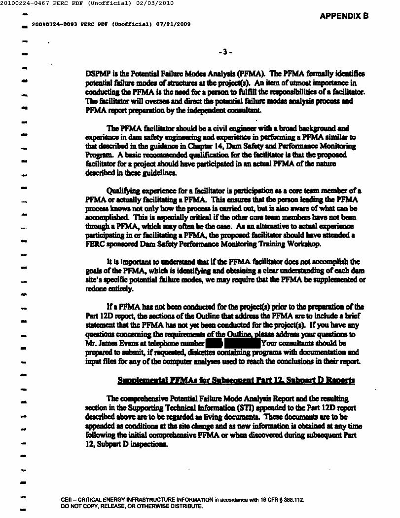
20100224-0467 FERC PDF (Unofficia1) 02/03/2010
- APPENDIXB.. 20010124-0093 FERC PDF (Unofficial) 01/21/2009
-.. -3-
-... DSPMP is duI PutaItiaI Failun: Modca Analysis (pFMA). Tbe PFMA formally idcaIifi.potadiaI failun: model of IInIcIuIa ItduI projccl(l). An item ofUlmolt importaDcc inc:oucIuctiDa duI PFMA is the IIIIIIII for • penoa. to fidfiU tile .... pOlllibiliti. of. facilitalor.Tbe ticilitalor wiD cmnee ad cIirect tba lX"enti'l failun: modes aa1ysia proceu aadPFMA report pnpuaIioD by the iDdepcndent ClOIIIIJ ..... '
Tbe PFMA ticilitalor sbouId be • civil eDJinlllll" with. broad bIckpouad aadGperieacc in dam safety nasi' iDs aad experience inperforaIiJII. PFMA limilar tothat deacribed in the 81"'''''''''' inCbaptcr 14, Dam Safety aad Perform' ...... McmitoriDsPropIllL A buic: P'CO""DCDded qualiticatioo. for the ticilita1ar is that the prcipDsedracilitator for • project shmIcI have participaled in an ICtUaI PFMA of the IIIdUnIdeacribed in these guidelinea
-----..-..-
QuaIifyiDg experience for • flcilitator is pIIl1icipatioD u • core team member of.PFMA or actually filcilitatiq • PNA. This __ thai the panon leading tile PFMAprUC:eI.1mowa not cmIy bow the prOCllll is carried DId, but is aIao aware ofwbat can beaccompIiabed. This is capecially critical if the oIber core team memben bave DOt beCIltbrouah. PFMA, which may often be tile CIIIft. AI an altenlative to actual aperieDccparticipati"l in or filcilitatiq • PFMA, tile propOIftII ficilitalor should bave ·!tn .........FERC IpOIIIOnId Dam Safety PcrformaDce MoaitoriDs TraiJIina Worbhop.
It is illlpOltaal to UIIdenIaDd that if tile PFMA ficilitalor does DOt ICCOIIIpIiah tilegoaIa oftbe PFMA, which il identifyiq aad obtaiuiDs. clear UIIderIIImcIi"l of each damIite'l specirac potential failure modea, we may require thai tile PFMA be supplemeated orredoae entirely.
If. PFMA has not beCIl c:oaducted for tbe projecl(l) prior to the preparatioa of tilePart 12D report, the aec:tioDI oftbe Oudiae that Iddreu the PFMA are to iDcIude • brief....oent that the PFMA hal DDt yet beCIl condncted for the project(I). If ,au bave anyqucatioIII c:onc:emilll the requirements of the 0utIiDe, p1euelddrelis your qneaticma toMr. Jamea Evana It teIqnme mil" ...... Your _ bouId beprepared to submit. if requcatcd, diskettes containi"l programa with doc ",lItioo IIIdiDput fil. for any of the compuIIr I11III,.. used to radllhe CODCluaioasin their report.
---..---..-..-..
SpppJ"Ppttll7'MA! lor 'shrppt Part 12,S,.....rt D • ..,......-- Tbe COIIIpIebeuaive Potential Failure Mode AnaIysia Report aad the raulqaection intile 8upportiDa TecImicaIlDformatioo (811) appmdrd to tbe Part 12D reportdeacribed above are to be reprded u tiviDs doc:umenta. 'l'beae d"""menta are to be........ cd u c:onditioua Itthe lite c:b"'F and u DeW iDCormation is obtaiDed Itany timel'o1lowiD& the initial comprcbeuive PFMA or wbCD diacovered duriql\lblequcat Part12, Subplrt D iDapectiooa.
------- CEil, CRITICAL ENERGY INFRASTRUCTURE INFORMATION in aa:onlance wHh 18 CFR §388.112.
DO NOT COPY. RELEASE. OR OTHERWISE DISTRIBUTE.-
20100224-0467 FERC PDF (Unofficia1) 02/03/2010
- APPENDIXB.. 200'0124-0o,3 FERC PDF (Unoff1c1all 01121/200'
-- -4-
- Therefore, for the Part 120 IDIpecaioas md lleport.s for tile dcveklpDultl tilted onEaclOllUle A IUblequcat to the seventh iDspectiODl1llCl1epcII1l, t'ormaI PFMAI wiD DOt berequired. hutad,. part of tile pnIPUIIioa for the iIIIpIICtioa, your perIODIId IIIId yourPart 120 CODIUltaats should nMew tile cUtiaa PFMAs, STIJ ud all otber projectdoc:umcDta matinl to the operation _ dam..rety of the damII since tile lat Part 12Dinlp"1ions Durina the inspactiona, your c:ouuJlanllad you IhoulcI orpniZl! adcooch'ct infonnallllJlPlemental PFMA ICIPons with your 1+ c.,,,,,tives md our PERCiJasr.eo:lDr to examine aay nMsiODI or additional faihue modes icIcntified dlll'ina thereviews.
------ PIeue inform the Reaional oftic:c when the Independeat CoIIIulflDta will inIpectthe ckveIopmcata listed on Fm....ure A 10 thBy may .ttmd Tbey wiD also conduct theirDam Safety inIpactioaI of l1li: cIevcJopmcnts lisled on Enclolurc A incoojUDCtion withthe IMepDndent Consultaats' inIpectims-
- The supplemcmu PFMA should be condw:ted c:maillcDf with Cbap«er 14 of thePERC Rnrin iDS Guic!elinn for !he EnI"MOIl ofHwlmpowc;r Projects. It is importlDtto main tile oriJinal PFMA n:port • pn:peNd 10 that the fiNIi..,., dilClllSion. andthouaht proc:cIIlCI of the oriainaI Potential Failure Mode AnaiYICIlCllion are reIIIined forIUIIR evaluations.
---- You are mni .... that nat .... tbaa 60 clays aftr:r the reports of tile independentc:ouultllltl are filed with the RqiOJlll Eqineer, you must submit to the RqinallEnain......tine copies of. plan md scbcdule for delipinl ud carryina out Ill)' proposedCCAiCX:tive IllCaIlll'l:l for OIII:hdevelopment--
Sinccrely,...
-ScoiorCivil Pnair:rDiviaioo orDain Safcty and IDIpec:IionI--- c:c: Public Files---..
-...
CEil - CRITICAL ENERGY INFRASTRUCTURE INFORMATION In accordance with 18 CFR § 388.112.DO NOT COPY, RELEASE, OR OTHERWISE DISTRIBUTE .
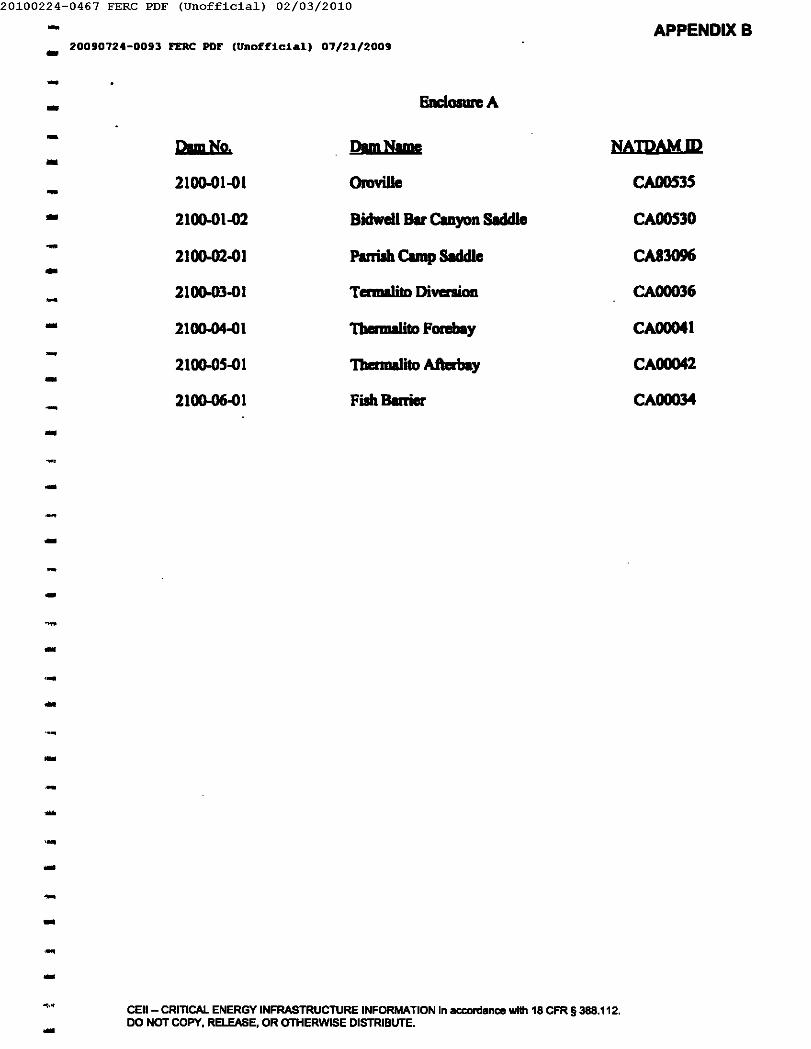
20100224-0467 FERC PDF (Unofficia1) 02/03/2010- APPENDIXB20090724-0093 FERC PDF (Unofficial) 07/21/2009--- Enclosure A
- NAmAMIDDIm No. DamNtg- 2100-01-01 Oroville CAOOS3S-... 2100-01-02 Bidwell Bill'Cuyon Siddle CAOOS30
- CA830962100-02-01 Parrish Camp SIddle...2100-03·01 Termalito Divcnicm CA00036-- 2100-04-01 1benDaIito Fcnbay CA00041
- 2100-05-01 Tbermalito Aihwbay CA00042-- 2100-06-01 FishBurier CAOOO34-------,----------<.•
CEil - CRITICAL ENERGY INFRASTRUCTURE INFORMATION in accordance with 18 CFR §388.112.DO NOT COPY, RELEASE, OR OTHERWISE DISTRIBUTE.-
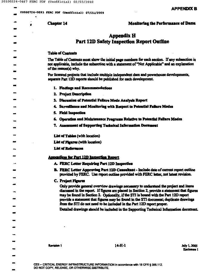
-20100224-0467 FERC PDF (Unofficia1) 02/03/2010
APPENDlXB.. 20090724-0093 FERC PDF (Unoff1c1.1) 07/21/2009
- •..-..---..-..------.-..-----.---..--------
Cbapter14 Moaitorllli the rerfol'1llUce Or DalIla
AppendixHPart 11D Safety Inspection Report OatllDe
Tale or eoataCl
The Tible or()mtmts IIllIIt &bow the initial JIIIF IIIIIIIberI for each IICIion. IfIlly subIecdon isDOt 1PP\iQb1e, iDcIude the mbIectioa with • IIalemIIDt or"Not Appliclble"lIId ID explanationorthe 1ellClD(1) why•For lic:cnIIed projecll that include IDII1tiple independeDt dmllIId powedJDuIe dcvelopmenls,..,.ate Part 120 reportI sbouId be published for each dcvelopmr:Dt.
I. Fladlap ada-Gm_datloal1. Project DacrIpdoa3. D..... or PoteIltlllll'lIII.re Mode AD..,... Report4. Surftl)lua ad MoIIltoriDI with RIspect til PoteIltlal hllare Model
5. FIeld ... ,.1iM6. Opendoa .. d MU ..... a RelatIve to Poteatlal ,an.re Mod ..7. Ailil _t or S.ppotIIDI TedI.leIIIl DoeII__
LIlt ofT ...... (with 1ocation)
Lilt of JIIprII (with 1ocatim)
LIIlof ....... ces
A. FEIlC Le..... Reqalrlq Part IZD l .. pectIaB. FEIlC Letter A,.,. ... Part IZD CanltaDt -lDclade elate orc:urreat repoIl outline
provided by PERC. Use report outliDe pnMcIed with PERC Ieaer, DOt IaIeIt revillioll.
C. Project .........Caly pIO¥icIe JIIIfftI OYCFYiew drawiDslaecCIIWY 10 IIIIdcntand the project IIId itanldiicullod intherepoll. Irfipres m:p1lCllClinSClc:Iioa 2, provideutltelnCDl that fiswamay be fOund illSClc:tion 2. OpIioaI11y,irthe STI is bound with the Plat 120 reportpnMde .......... ent that fiswa may be found in the STI cIoc:uma; duplicate cIrawinp.&vm tile STI do DOlueed to be iDcJuded in the Part 120 I'JIOft JIIOPCC.Decailod drawiIIp sbou1d be iacluded in the SuppodiDa Tcchnic:allnfixmalioa doc:umant.
14-H-I I..., 1.200.5Ene .....
CEil - CRITICAL ENERGY INFRASTRUCTURE INFORMATION In aa:ordance with 18 CFR § 388.112.DO NOT COPY. RELEASE. OR OTHERWISE DISTRIBUTE.
20100224-0467 FERC PDF (Unofficia1) 02/03/2010- APPENDIXB.. 200'0724-00'3 FERC PDF (Unofficial) 07/21/200'
- Cllapter14 MODatom, tbe PerformaDee of Da. •...- D. lutra .... doD MOIIItoriD.o. .. PIotI
List each Ii.- IIIcl drawina iacluded in the rqxxt. OpIicmaIly. inlllnllDelltllion plocsmay be pllccd in SectioD 4 of the rqxxt 1IIIiI. slalcmCld included in Appeadix D tbat theplots may be found in Section 4.
E. .Optionally. _ or all of the photoanpbs may be included inthe ijljHopriaae sectionI ofthezeporL Ifpholoaraphs_ i"Clucled within the report, povide a lilt of thepboIopphs aDd the correaponcIiDa pep number in Appendix E.
F. lalpectIo_ CIIec1d11t1 Hdlor FJeld Notes (OpllOD_1)G. aper ..... ad Malateaaace Dec __ .. tln (lfreqalred)
..
..---------..-----------..
Revillaa 1 I4-H-2 July I. 200SEac..... 1.--- CEII- CRITICAL ENERGY INFRASTRUCTURE INFORMATION in accordance with 18 CFR § 388.112.
DO NOT COPY. RELEASE. OR OTHERWISE DISTRIBUTE.-
-20100224-0467 FERC PDF (Unofficia1) 02/03/2010
APPENDIXB_ 200'0724-0093 FERC PDF (1hI~£.I.ca.J.1 07/21/2009
-I------..
-----.-
-------------------
Cbapter14 MODitorIDI die Perfol'llWlce 01 Dams
1.0 lIIIidiap ad Reeom_daduI'Ibis Section includes a IIIIIUIIII')' of the Pan 120 IDdep IIIIIcot Couult8at's findiDp IIIIIlMussmentlllllll the Part 12D Indcpcndlllt CcIIIIul1lDt's conclusions IIIIIlrecammend.tians.
l.l FiDdinp
1.1.1 SUDIIIIIr)' asaameat of the PFMA n:port
1.1.2 SIIII1IIIII)'III ..lilt of the Surveilllllce IIIIIlMonitaring PIIn1.1.3 SIIII1IIIII)'of Field InspecIioD Findinp
1.104 S1III1IIIIIY of OolM IIaIUI
U.S SIIII1IIIII)'~ of"Supportiq TecbnicIllnfillmaliOll" doc:umeat
Note: Specificllly identify lilY new c.leuilliona prepared subsequent to thepnMous Part 120 RIport.
1.2 ConcJusionsTbc CODCllllioasof the Independent Cooml1lDt nIpIdiIJI the COIIditiOll and suitlbilityfor eontiu"CIClllfe IIId reliable opeaMlioa oflbe pmjcct IIIIIlapec:ific _11IIi0llSRpnliq the iafixmIIioD ja eICb Sectioo oflbis Pan 120 report.
1.2.1 ConcIusiona tepldiaa Ibe lllilibility of the Project fiJr COIIIiaued life IIIIIlreliable operation.
1.2.2 CoaeJIIIioIII repnIiaa the Project Description1.2.3 ConclIIIions repnIiaa the PotmIiai Failllnl Modes Analysil Report
1.204 ConcJIIIicms RpIdina the SurveillaDce and Moaitoriaa Plan1.2.5 CcmcI1IIions repnIiaa the Yield IDIF actioa
1.2.6 Conc1usic1111 repntinl the ()pInIioaI and MainteaIace PnIpIIIII
1.2.7 Coacllllioal repnIiaa the SuppwIiDa TeabDicallafbrmlliOll
1:3 RcwuaomdllionaThe recCIIIIIIIeIId oflbe Jadependeat Coasul1lDt to improve or _jatain thecondition IIId lllilibility fiJr coatimwl ufe IIId reliable operIIioIl of the project IIIdapecific: recoall4""'l.ti .... reprdiaa die iafimallioa in eICb SecIion ollbis Part 120report.
1.3.1 R«allilllP,tiOll' repnIiaa the lllilibility of the Project for ccmtiauad lifeIIId Rliable opcntioa.
1.2.2 R.eQ"ummillians Rprdiaa Ibe Project Descriptioa
1.3.3 R.eQ-jIIIeaulllians Rprdiq Ibe PoteaIiaI Failllnl Modes Analysis Report1.3.4 Recommeadatioas RpnIins the SurveiUance .1IIdMonitoriaa PIIn1.3.5 Reooillmendllians Rprdiaa the Field 1nIpccti0ll
RmoiDa 1 14-H-3 July I. 200SEact-el
CEil - CRITICAL ENERGY INFRASTRUCTURE INFORMATION in accordance with 18 CFR §388.112.DO NOT COPY. RELEASE. OR OTHERWISE DISTRIBUTE.
20100224-0467 FERC PDF (Unofficia1) 02/03/2010- APPENDIXB.. 20090124-0093 PERC PDF (Unoff~c~al) 01/21/2009
- Cbapter 14 MoaltoriDg lbe Perf'onaaace of Da .. ,-- 1.3.6 R_mendations repnlins the ()pcraIiOlllIllCl Mainlelllllce Prograus
1.3.7 Recommendetjops repntina the SupponiDg
1.4 CertificationNote: By tisainl this doc:WlllRI, the PIlI 120 Indcpendent COJIIIdllDt iSIIIliD& dillthe entire report bubeen developed by IIICIUIIder!be dilection of!be UDdeniped.The PIn 120 Indcpeadeat Consu1tant IbaIllIIIkc I clear lIIlCment that helshepaeraIly COJICIIIS wilh die ISIIIIIIJIIions methods of analysa, and rauJlI of allstudies documented in the n:pan.The PIn 120 Indcpcndent Consubant is lima 1Iki... responsibility for the Part 120repon coatcnts IS I Professional &I&inecr.
..---..---,-
1.4.1 Lilt of all field iDlpec:lion participata1.4.2 Refcn:nce to PERC 0rdeI" 122 daIcd Man:IIl, 1981111C1paragraph 12.37 (c)
(7).
1.4.3 Sipature(.) of PIn 120 Indepeodent CcmsuItant{.) and PE Stamp
Sa:Appeadix A: nRC Letter Req1IIrIIII Part 12D I_peed_Sa: Appendix B: nRC Letter Appnmal Part 12D Con ...... t - (Include dIIc ofcurrent repon 0IJlIine proWled by PERC)
2.0 Project DeseripIlDD
2.1 Brief Project DacripIioa
For each major elcmcnlllllllllCillary IIrIICIure, provide • brief d-=ripticm of die t)1IIIof ItnICIUre, paeraI dimeDIions, ell:. The detailed project dacripIion wiD be inthe"SuppcII'IiDg Ta:hnicaI JnformaIicII1" doc"ment.For malti-pmject or development Iiemm, include I brief oudine ofbow this lite filswiIh the other projects.
lncJude.1hart paragraph wilh vcrybriel"project history. Wbcm CCIJIIIrUCted. whenmodified, any incideatI.
2.2 HGIId PolentiaI Cluaification.Baed lID views Iiom the clam, otber project worb iDSpected IIICIc1ilCllllion wilh theIioauiee, document Illy cIJanaes in~ or dowDIIIam GIIIlditioas tbal mishtIfl'ect the HIZIId Potential Clanifieaticm. Revi_ wilh the liceaseelhll mctboda IIICIlIIDIII1pIionsIIIed to develop Ibe IDF. If the lOP i.1ess tban the PMF,the IC Ihouldc:cmfirm _the lOP is stiD valid bIsed 0Il1ll1llelllllClll of the doWI1IIrCImconcIiticms IS noted above.
2.3 Summll)' of SIIIldard OpInIins Proc:edura
---------------- ItcviIioa I I4-H-4 July 1,1005
Ear"n I--- CEII- CRITICAL ENERGY INFRASTRUCTURE INFORMATION In accordance with 18 CFR §388.112.DO NOT COPY. RElEASE. OR OTHERWISE DISTRIBUTE ...
20100224-0467 FERC PDF (Unofficia1) 02/03/2010
.' APPENDIXB
.. 20090724-0093 PERC PDF (Unofficial) 07/21/2009
- Cupter14 Moaltorlq tile Perfol'lllaace Or Dams..
-2.3.1 P\IIpoIe oCProject (Run oCriver. atoraac. flow IIIpICIIIIIion, tlooclllllCbarae
IIarIp, COD1IoI RICIVC, pumped IIIaJIF, etc.)2.3.2 Rmnoir rule curves by __ (iaclucle Int_ RurlOirlevel opcntill8
IcveII and 1'CIIric:Iioas oC reservoir 1c:vc1due to IIfcIy CIIDCCIIII, ifmy)2.3.4 StIIIdanI pie opc:nlion procedun:s (lad and CoIIowin& pteI, emc:ageuc:y
pGWWlystems, etc.)
2.4 Modific:llions Ccmducted Cor Project SafetyDoc"ment any maclilbtiOlllto poject works since the '-It Part 1m iDlpeclion tbatbave been cIoDe to improve poject 1IfcIy. (i.e.: ipillway plCI reinCon:ecl, '~IPIIFdniD, berm lidded, crest railed, poIl-_PODed I1ICbon iaIIalled. tbuaclatiOll dniaI orrcIichwelll clelned. etc.). In the nc:xt Put 1m Safety IDIpectioa RIport, th.e ilaDSwin beeOJae part oCSectioa 2.1. nul iIICorauIicm IbouId be Cully dacribed in theupdated "SupportiDs TecImic:aIlDCormItioa" doc:umeat SIIbmitled with the Part 1mreport.Do not iaclude routine IIIIinteaaace such • llllit owrbauI, pie pIiDtin& etc. Note,that .. craton. ~ and tnnImissioa &cililies are excluded from the Part1m polfllll1lllller 18CFR subsection 12.35.
2.5 Flood History
2.5.1 Flood oCReocmI, PMF, mF2.5.2 ZeIO lieebolnl ipillway c:apIICity2.5.3 PeIk ipiIlway cIiIc1uqe duriDa lilt five ,.. period2.5.4 PeIIr: _erwir eleY8Iion cIuriD8 Jut five ,.. period
...
..------------- See Appendix C: Projecl Ji1pnI (Note; ICth~ STl ill bowIII with thiII rIpOI1, do IIDl
duplic:ale fipres)
- 10 DIInIIIaIlel ......... "aIIare Made All..,... Report
Do DOl iaclude ICICUI'ity __ ia the Part 1m report. For IiceaIed pmjecll that iaclude. mWtiple illdepePmt cIIm and JI01IIerbouIe dcveIopmcnta, ...... _ PFMA 1IUdieI ....
reporIIlbouId be DIllIe Cor each deve1opmeat.
3.1 GeDenIIdealifY the CoR TCIID ............ and their affililtiODl, wIlD clneloped theCOIlipiillbeuive Potential Fulure Model ADIIysis (PFMA) or ill update. Note dill tbepIOCCII wu ia ICCOIdIacc with FERC "EqiDIIeriaa Goidc1iae Cor the EVliUllioa ofH;rdI..-- ProjectI, "CbIptcr 14.
3.2 ME' went orPotentill FIiluR Mode ADIIysis Report
AIIeu the viIbIc poten:tiiil flIilure mod. ideDtified in the PFMA I'IIpIIIt. TJac:. wouldgenenIIy be CItepy I throup CItepy 3 PPM•• PIovidc m u. rn'!!Dl orthe
-----...-- ReviIiaa I 14-H-5 luIy I, ZOOS
Eaclasun I-...- CEII- CRITICAl ENERGY INFRASTRUCTURE INFORMATION In accordance with 18 CFR §388.112.
DO NOT COPY, RELEASE, OR OTHERWISE DISTRIBUTE ....
20100224-0467 FERC PDF (Unofficia1) 02/03/2010- APPENDlXB20090124-0093 FERC PDF (Unofficial) 01/21/2009.... CUpterl4 Moaiaorla. tile Performaaft of Daml-
.-
,..,...bl_1IId completeD" of the fililme JIIOCIo ICeIIIrio IIId whether !he PFM.idenQfied baYc a nil pOllibility of_ Potential Failure modeIlhouJd beIiIIed in onIcr ofimportancc. &ch PPM _should include:
• A ds:ription that includa the sequence of ccmditiDDlIIId evCIIIIIhat wouldlad to !he pobIIIIW failure mode;
• An IIRIIIIICIIt oftherilk reduction opportImiIies for CIICbPPM; IIId• An ~ of the Surveillmce IIId MoniIoring Plan for ach PPM.
For example, the report would be f'ormalted .. follows.
3.2.1 PFM I. (i.e. JntcmaI ClUlion, pipiD&)3.2.1.1 DaeriplionofPFM (may be takcnlrom PFMA report)3.2.1.2 All DeDt ofRilk ReeI'lC'iDD ()pponwIitics3.2.1.3 ~ ofSunoeil'-elllld Monitoring Plan
3.2.2 PFM 2. (i.e. Seiamic incIucec\ defonnaliDD)3.2.2.1 Description ofPFM (may be taken from PFMA report)3.2.2.2 ~ of Risk Reduction Opportunities3.2.2.3 An cent of Surveillauc:c IIId Monitoring PlanEtc.
-------------- 3.3 Are there IIIIW potential failure model that have been identified and IddreIIec\ in this
report or that IhoWd be al.aln d? If10,include the appropriate Description oflhePPM. AlII mmt ofmiriptiCIIIac:tiDDland AI_a of the SMP II eli_eelabove.
See "Supportina TICbnic:aJInformation" cIoc:umcat: PaIa .... Falun Mode Aa..,...Sa.dJ RepoI1 (Update II appmpriate)
---.-- 4.0 S.mIIlDa ud M_1torID1wItb Respect 10Potea .... hllun MadaNote: Review and .-neat ofSurveillancc IIId MonifOriDgPlans must always be donelam the point of view of potential f'Iil_ modII. Allbouab !be primary a.. = .+ent iawithic:apect to the pokIidial fililmemodII idIIItifaed in the PFMA lbIdy, the 1DcIe!*4entCoasultaDt must dateUDina ifrhcn l1'li potcDtiaI filii.... modes DIllpnviOlllly llldaiillCll ornot adeqaaIely consideaed.For !he puipOIII ofthia ICCIioa, a 11aaeabold LcveI ildle value UIed in the analysil ordelilPlo or ia estIblilhec\ lrom the hiaIoric: nICOId. An Adioa Level ia the inscnamentnlllting thai triuen inueaec\ IUlVeiIIlDce or iii _geilcy action.
4.1 Opendor's Suaveillanee PruanmDllilylweekly opentor'l illlJleCtionI and aepoatI.
4.2 Active IDIIrumentation: Im:lude a ac:beauIic figure Ibowing locaIion ofinmumentatioo (not dcIIited or Cl'CIIIIIICtion).
--.---..-- RmliaDI 14-H-6 Jaly 1,200'
Eaclalun: I--- CEn - CRITICAL ENERGY INFRASTRUCTURE INFORMATION in_ance willi 18 CFR §388.112.DO NOT COPY. RELEASE. OR OTHERWISE DISTRIBUTE.-
20100224-0467 FERC PDF (Unofficia1) 02/03/2010... APPENDIXB20090124-0093 FERC PDF (Unofficial) 01/21/2009-- Cllapter 14 Moaitorial !be Perfol'llUlllcc 01 DIIIIII-
-Thia will 'illY by project. Discuu OIIlytile iDItnimeaIIlCbIaI1y IIlIbe project. IsiDItrIImeDtaIio in II:CCIIdIIK:e with Cbapler IX oCtile FEllC ~ GuicIeIinefor the Evaluaticm ofH)Ckopower Projects''? II the ~ fimc:Iioaioapioperly? Etc.
• PiCIODICIen• Weirs• SeUlemcntlllipmeal DlOnuments
• Cnckpps• UpItreun river lUIdIornUnppllllious• Hadwatecltailwatcr (Ilann systems)
• etc.
-------
-
4.3 TInsboId IDd Action 1eveIsFor eacb inItnIment, or &JVIIP ofiDllruments • apprvprWe, pJOVide a t.ble ofThreIboId IDd Action level •• defiDed above.
4.4 Rewlina proeedureIIfnIq_yFor eacb iDItIumcnt, or poup of inIIrUIDCIIlI_1IpprVpIiIIle, di_:
• Data lCCluisition procedura (mm"II'IUtomated)• DIfa emU"OII procedures (pnIc:eII; iIdIIla evallIIted ina timely _ by •
qualified !!!JIineer; _ JNdinp compared to Tbnsbold &lid Action IcveIadefiDed for ada iDaIrumeDt)
• Spurious rednp (_spurious JNdinp c:onfirmecl or ap..... - JROYided)4.5 AsrMIDICIIl ofIutnunentation DIIla IDd SurveiIImce &lid MoIIitorina PlEa RcIaIive
to Potential F.nun Model
-------- lDc:lude newly ideatified potential faiIun modM-- 5.0 rteId lupecIIGa-- 5.1 F"1IIdInspection 0bIInaIicmI
For each e1emeat oCtileproject (i.e.: epillway, artbfiIlemhMknwlt, pavity sectioa,i1\lake, powerbouIc, c:cmveym:c syI&Im, de.), obaave IIId n:port .. obIerIIIliaaaof tile followina iaIIIcs _ 8ppI'Opriate. JJII:lude pbotostaplw to ~ lipificantproject feIIlura &lid oblcrvlllicms. IfIIIinspectioa c:ha:tlilt is used, iDclude • copy oftile checlrJi" Appendix F. A lite ipeCific iIIspection cbeclrJist IhouId be formltted toiDclude ipeCific viIual surveillalll:e itau identified inthe PFMA.The iaIeat of this IICIiOII iIto biPlisht chanpd coaditions for the report reviewer,not to document IIIIimportant or minor cldaill .
-...--.....- ReviIiaa I 14-H·7 JuI, I, ZOOS
Ead"'" •-..- CEII- CRITICAL ENERGY INFRASTRUCTURE INFORMATION In _onee with 18 CFR §388.112.
DO NOT COPY, RELEASE, OR OTHERWISE DISTRIBUTE.-
20100224-0467 FERC PDF (Unofficia1) 02/03/2010- APPENDIXB.. 200'0724-0093 FERC PDF (Unofficial) 07/21/200'
- Cllapter14 Moaltorla. tile Perform.ace of Dams..- The rcpon IbouId be in text I'onnll by strvcturc or element IIIdnued individually.
For each IIII'IIctIIre or element of the pIOject, the PIrt 12D Jodepcodent ConsulbaltIbould COIIIider the f'ollowins itellll _1ppIOPriIle:
• Settlement• Movement - includinslbulments (CIIICbor 0Iber sips of diJIreu or cbanp)
• Erosion• SeepaplLnlrap• Cracking
• DeteriorIlion• spiilway pte OperIlioalStIIDdby Power (At a minimum, the Part 120
JndepIadmt COUll",,", needs to 1eVi_ the licensee', annual c:er1ifieales ofspillway pte operation aod interview project operatins staff to _ thatemergency baI:laap .,atems work IIId that operIlius perIOImei blow how to usethem. At least one spillway pte should be operated IIleast _ foot during thePan 12D inlpec:tion using the ItaIIdby pnerIlor.)
• 0uIletISluic:e Gale Operation• Wiler CXIIIV8)'IIICC ayatans (c:aaalil Dumes I pCIIItCICks I hlMela I surge
cbImben, CIIIClpIICY bypass or cIoauR Iyttems, eb:.)
• Ft'UllllatiOll DraiDlRelicf' Well 0perIli0n• Evideuco ofbiBh uteaian or uplift pI! Dca (1IInIC1Ura I fo"odlliOlllI abutmenta)• 0bRrv1lions of ""'jment tnnsport (pipin& evicIence)• ObRrvIlioas of aeepI, wet -.. apriDp, p:eo ps• Other Pa1iDcat 0bIavIli0lll
..-..-..--------- S.2 StIlUs ofResponle(s) to R_meodation(l) in Last Put 12D Report.
S.3 Field 0bRrvIli0llS with RCIp"'ct to Potential Failure Modes
Document field oblervlliona pcrtiDeat to each polIDtiai failure mode DOted inSectioD 3
S.4 AdequacyIOperIl of Public Alert SyttemsNote: Are uplbAi .. spillway wamin& buoys, aod cIownstram .u-aod Ji&htsopmb\e?
--------
See Appcadix E: 1• .,.1Ioa PIIooaopapU (Optioaally,1CIIIIII or all of the pbotoppbamay be included in the appropriate sections of the 1qIOIt. Ifpbotopapbl_ includedwithin the report, pIOvide in Appendix E a list of tile pbotopapblilld the ccmapoucIingpap number)
See Appendix F: lapeedoa Cleek LIlt (optional)
---- Revisiaa 1 14-8-8 July I. 2005
EDc __ 1--- CEil - CRITICAL ENERGY INFRASTRUCTURE INFORMATION in ac:<:ol'danCllwllh 18 CFR §388.112.DO NOT COPY. RELEASE. OR OTHERWISE DISTRIBUTE.-
20100224-0467 FERC PDF (Unofficia1) 02/03/2010- APPENDIXB.. 20090724-DD93 £ERe PDP (Unofficial) 07/21/2009
- Claapter 14 Moaltorial tile PerI'ol'lllaKe or Da...-.... 6.0 0pen .... 1UId ce,........ RelatIve Co ....... ' .... n ModelDo DOt iDclade Iel:Urity i in the Part 120 iDIpec:don NpOIt. If ~ oflipiftcant o.tM ~ -JUlIe, include in IIJIDrl forpOIIIible new potmtiaJ fiilure modemalyail •
6.1 SIIIIIIIIIII)'ofPFMA idadified O&M issues (fi'om PFMA report)
-..-..- 6.2 OperaIiODaDd MIinteaaDce Proc:edun:s
6.2.1 CommUllication/R.aponle
AcIdresa IdeqUlCYIIUI!'elilbilily of ranote moaitorin& COIIIIIlIIIIica IIUIcontrol.,.... (0penIi0lll I InIIrumeatatiOD I Telwn""'Y - Do the systemsproYide IIIequatc rclilbilily aDd redUlldlncy? em. specific spillway pte,valve or other pJUjec:t c:omponenl be operated nmoteIy 01\ dcmaDd?)
6.2.2 EleclricallMecbllllical Systems• Spillway Gale Moton (JinaIIiDe vo1tap.1IIIpeI'&Ie draw, motor name
plate ratiDI infimllllliOD)• Standby aDd lednMet Power Soun:cI• ~AlIIOaUItic Opemtion ofGatea IIKIValva• Gale 0penIi0D Seq_
:;.• Icins protectiOD (hatenIbubblenhelcrvoir leYellalriclioa)
, 6.2.3 HIIIIIID FICIOn• AdequaIe Stafff'or EmIrpDcy RCIIJIOIIIC(Multiple Sites)• Reliable AcccsI Raala (winlerlstorm coaditions)• TniDin&• E1ectriciIllllMecbllliCllLlborcn• ~uate TUDC Co Raponci• Call Out Systems (time for _ to raa:b lite after callout)
6.3 AI_sment ofO&M PnJc:edurea Relative to Potential Failure Modes
..-..-..-..-..---......-..---..-...
Rewisialll 14-H-9 JuJr I, 200SF1IcIoIIn I-..
- CEil - CRITICAL ENERGY INFRASTRUCTURE INFORMATION in accordance with 18 CFR §388.112.DO NOT COPY. RELEASE. OR OTHERWISE DISTRIBUTE ....
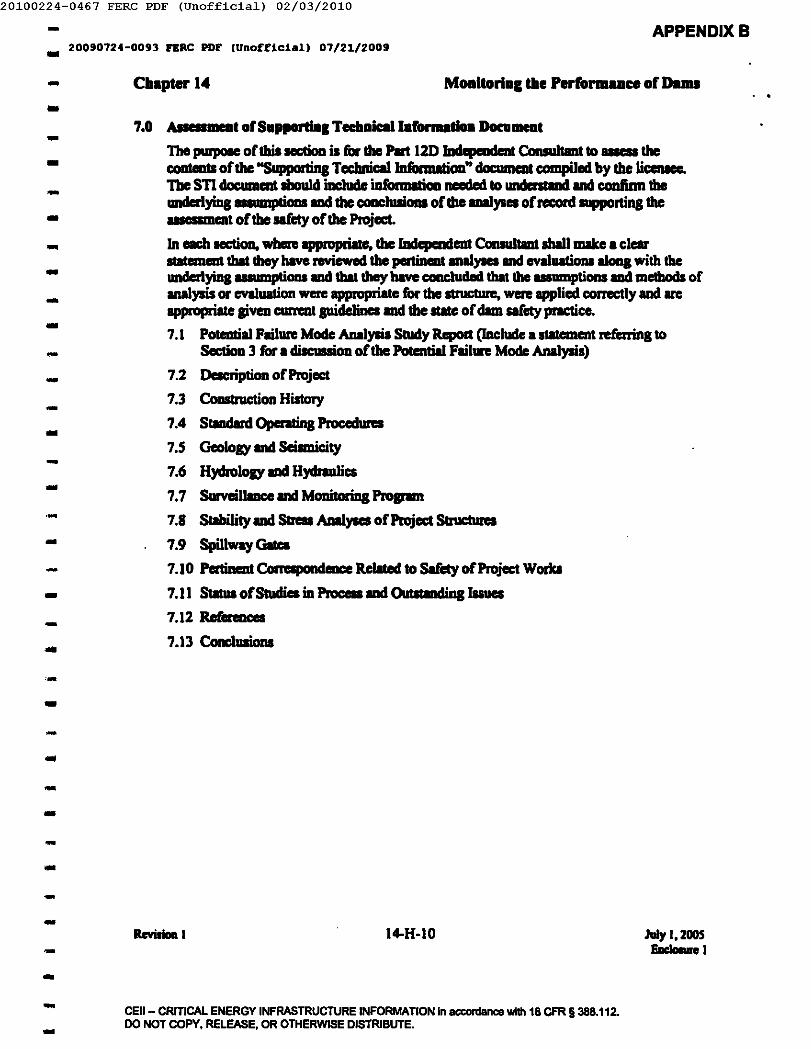
20100224-0467 FERC PDF (Unofficia1) 02/03/2010
- APPENDIXB.. 200'0'24-00'3 FERC PDF (Unofficial) 01/21/2009
- Chapter 14 Moaltorial the Perlonauce oro ......
-7.0 AIIeII __ olSapportial Tecbaiallal'onudOll Boca __
The ~ oflbillllCtioa is for IIle Pan 120 1Ddcpmc!rnt ConsulIant to_1Ilecoatents orllle "Suppodins TccbnicailnConllltiOll" doc:umcat compiled by the IicenIee.The sn document Ibould iDc1ade iIIt'ormatioaneeded tour.dailll ..d and confinn theandcrIyins IIIUIIIpIicms IIId the c:oaclusioM orllle ..... yses orrecord supponina the.. w:nl orthe.mty orllle Project.In each HCtioD, whcre approprialc, IIle IadcpaMleat Comuitllll sIWllIIIke • clearIItaleInIIIl that they have reviewed the pertiDeat IIDllyses and evalualiona aloaa with theuncIcrlying UIIIIIIpliOlll ud that they have cam:luded thaI the _amptions aad methods ofutalysis or evaluation were appropIiate for the atruc\IIre, were applied correctlyanc\ areappropriate &iVeD c:um:al pidelines IIIId the IlIle of dam safety pnlCtice.7.1 Poteutill Failun: Mode ADalysis Study Repod (Include a sIaleI1Ienl referring to
Section 3 for. discussion orllle PoIatIial Failure Mode Analysis)
7.2 Descripticm of Project7.3 Ccmstruction History7.4 StIIIIdant ()periling PIOcedIlRl7.5 Geology and Seipnicity
7.6 HydroJoay and HJdnulics
7.7 Surveilllllce and MDIIitoriDa ProJPIIII7.8 Sllbility anc\Saess Analyses or Project S\nIClUIes
7.9 SpillwayGita7.10 Patincnt Conapondeace Rebted to Safely orProject Worka
7.11 Status or Studies inPnx:eD anc\Oubtandina Issues7.12 Rufea_
7.13 Concllllions
-....---..---..---..-.....-..------ IIcYiIIaoI I I4-H-IO JaIy 1,2005
EacIoIure 1--- CEII- CRITICAL ENERGY INFRASTRUCTURE INFORMATION in ac:cordance with 18 CFR § 388.112.DO NOT COPY, RELEASE, OR OTHERWISE DISTRIBUTE.-
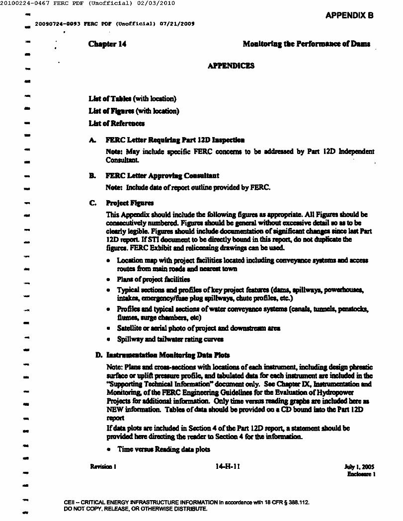
20100224-0467 FERC PDF (Unofficia1) 02/03/2010- APPENDIXB.. 20090724-D093 FERC PDF (Unofficial, 07/21/2009
eII.plerl4 MODltoriD. tH Perform.Dee 01 Dams-... APPENDICES..- LIlt ofT ... _ (with location)
LIlt of 1I'Ip .... (with 10CId0n)LIlt of Relereaca
-....A. FlRC Letter RequlrlDl Part 12D IDIpeedoa
Note: May inc:lude specific PERC conccms to be addressed by Part 120 IndependentCcmsultmt .
B. PERC Letter Approvbal CoII ....... t
Note: Include elite ofreport outline pmvided by PERC.
C. Project FIp ....This Appendix should include tbc followins fiames uappropriate. An Figures should be~ve1y IIIIIIIbcftd. Fiprellbould be pnerII without acmivc detail 10 u to beclearly le&ible. Fiames IbouId include documeutatiOD of llipific:llllt ""'" .. Iiace Jut Part120 report. IfSTI documeot to be directly bouIId in Ibis report, do DOt "uplicate thefiprel. FER.CExhibit IDIIn1iCllllins drawinp can be used.
• LocItion map with projec&liIcilitieaIoclled iDc:ludin& conveyaace .,... ... _routes fiom IIIIin lOads ........ _ town
• PIanI of project ficilitiea• TypicallIICtioaa IOd pmJi1ea ofkeyproject feat1Ira (dims, apil1_,., powabousea,
intak_, -aeacylfilse pllll8pillways, c:Iwte profiles, etc.)
• Profi1ea IDIItypical sectiou ofwater convcyaace ayItemS (canab, bmnelS, peIIItoc:b,flumes, IUIp ch""""n, etc)
• Satellite or..w photo of project IDIIdowasIream Ira
• Spillway IDIItsiJwater ratin& c:urvea
D. lutnlmeatatlaa MoaitorlDl DIta PlotsNote: PImIIIDIIem. sections with Iocarioas of eII:h inIIrument, iDc:Iudiaa deaip phreaticsur&ce or uplift pi: lillie profile, IOd .... ,J ..... cilia for each inIIrumeat arc iDcIucIed in the"Suppottiaa Teclmicll 1nfiInDation" docIImeat only. See Chapter IX, IDsIrumeDtetioo endMonitorin& of tile PERC Enain=inI GuideliDel for the Evil!!""" ofHydlOjiOYlerProjectJ for Idditicmal infotmetion. Only time venus taIins JPII\IIarc included ben: uNEW iJIfonuation. Tablea of cilia IbouId be provided GO a CD bouDd into the Put 120reportIfcilia plotIlRI inclwled in Section 4 of tile Part 120 report, a statement sIIouId bepmvidad bere directilll tile n:ader to Sectioa. 4 for tile infonnllioo.
• Time vcm. Reading .... plots
-..---..------..-..---..-..-..
RevisiaD 1 I4-H·1I lui, I. 2005I!III:'-e 1--- CEll - CRITICAL ENERGY INFRASTRUCTURE INFORMATION in acc:ordance with 18 CFR §388.112.
DO NOT COPY. RELEASE. OR OTHERWISE DISTRIBUTE.-
20100224-0467 FERC PDF (Unofficia1) 02/03/2010- APPENDIXB.. 20090724-0093 PERC PDF (Unofficial) 07/2~/200J
- Chapter 14 Moaltorial the PerfOrmAaft or DamI..- • Plot III data to dale, not just Jut five: years (IItem1live: is to plot Jut IS yean and note
historic rmge for each UDit)
• Do not put too IIIIIIY iDatruments on one plot• Try to put III iDstnImeIIIs Iiom ODe: sedioa or profile on the: IIIIIC plot• MIlk tip cleutioo, 1IIIICn:CDIId 1engIh. ground c:levItioa ad top orpiezomeccr
elewlion £or each piezometer on the data plot. This information CIIl be: provided in aTable to eDhIncc lelP1rility of the: pIPh.
• Use symbols lIIIdIor different line types for each UDiI, not jllll eolors (eolors do notrqmJduce inblal:t aDd white ad some people are eolor blind - Note: that yt:llow IIIIlblue:do not RPJUCIuceon Xaox 1IIII:hinc:s)
• Include hc:IIdwIIcr IIJd tsitw.ler levels 011 each plot• Force 111time: ICIleI to IIhow filII yaK" ~CI fiom Imury throuah December• For multiple plOll for the _ project, force verticlllllld horizontaIlCIles 011111plots
of the _ typc: to have: Che SlIDe selle or total ranae 10plots CIIl be: directly.overlaid
• MIlk threshold vllues• Show monthly pRCipilalion on one Ihc:c:t• MIlk ICIion levels nquiriq emeraencY response
L I......... ft.....,..F. JupecdoD CIIecIdIIt (optIoaal)
..-..---------
-----------...- IIeviIioIII 14-H-12 July I, 2005EacIaI1IIe I--- CEII- CRITICAL ENERGY INFRASTRUCTURE INFORMATION In accordance with 18 CFR § 388.112.
DO NOT COPY. RElEASE. OR OTHERWISE DISTRIBUTE.-
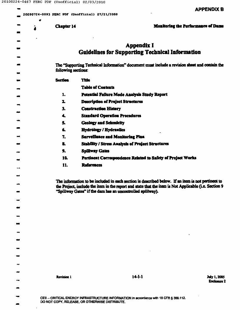
-20100224-0467 FERC PDF (Unofficia1) 02/03/2010
APPENDIXB.. 20090724-0093 FERC PDF (Unofficial) 07/21/2009
•- i----..-----..-..-..--
Claapter."
Appendix IGuldeUnes ror Supporting TechDlcallDformatioD
The "Suppor1ina Tecbnic:allafonnalioo" cIoc:umIInt mUll iIIclude a revision Ibeet IDIIcontain tilefollowiDs 1ICIi0lll:
I.Z.
3-
"-506-
7...,.ID.II.
-
TltIe
Table or Ca... 11
Potdllal Fallue Made AlIa.,. SIDdyReportDelcrlptloa of Project StractansCoutractIoII a....ryStlllldud Operation PIocedans
GeoIoD' .. d Selndl:1ty
8,. .... ' 8ydraaaaSaryem .. ce .. d MoaItorIIIl PI..StabDity , SIrIIs AIIaJpI of Project Stractans
SpJIIwaf GatesPerdaat COl"l'llpoadeace lWated to Safety or ProJect Worb
RerIftllCa
The iDfonnalion to be iDcluded in each lICIian il described below. If11\ itaD is DOt jHI1inea1 tothe PIojoct, iacludc Ibc itaD inIbc report and Itate tballbc itaD is Not Applicable (i.e. Section 9"SpiUway G..... iflhe dam bu an WIWIIInIIlecl !lpillway) •..
---....--
,.
-14-1-1 Julyl.~
Eaclaaue2
CEII- CRITICAL ENERGY INFRASTRUCTURE INFORMATION in accordance with 18 CFR § 388.112.DO NOT COPY, RELEASE, OR OTHERWISE DISTRIBUTE.-
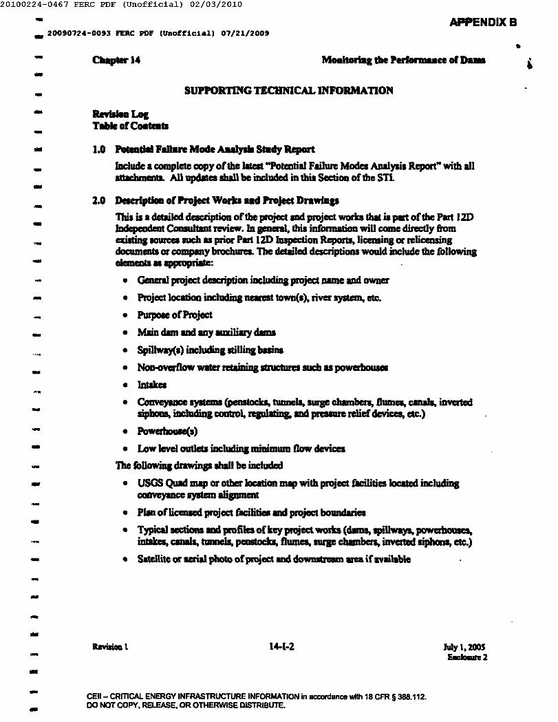
20100224-0467 FERC PDF (Unofficia1) 02/03/2010- APPENDIXB.. 20090724-0093 PERC PDF (Unofficial) 07/21/2009
•- 0 ....... 14 Moal..... diePerf_ce or.,...-- SUPPORTING TECHNICAL INFORMATION- RmllDllLocTale of COlI_II-.. 1.0 ..... d .. 'due Mode AuIyIII 8mdy Report
lDcludc a completel:OllY oflhe lalelt "Potential Failw-e Modes AJIaIysil Repon" with allattacbmmts. All updates sball be included in this Sec:li0ll of Ibe STL
Z.O DeserfpdoIl of PnJect WorkJ aad PnJect Dnwia ..Thil is a detailed description oCtbe project IIIClproject works !bat is part oCtile Part 120IDdcpeDdrot COIIIIIItaal review. InpaeraI. Ibis informalion will come directly fromexistins - IIICh as prior Part 12D InspectiOll RepoJtI, licensilll or relic:ensi1l8ciocumlDtl or company brochures. The detailed descriptiOlll would include Ihe following,1emeDtS II ippIQpriatc:
• Gem:raI project desc:ripti0ll includina project IUllDCand IIWJII:I'
• Pruject loc:atioa includiDa ncaresllOwll(s). river system, etc.
• PwpoIc oCProject• Main dim and .Y auxiliary dams• Spil1way(I) including stilling basins
• NoIMmrflow water retainiD& IlnIClUrCI suc:b as powerhoIua
• Inlakes
----------- • Convcyucc syIlCDII (penstocks, tunnels, .... cbamben. Dumes, canals, iDYCr1cd
sipbcma, iDcludiD& COIIIrOI, replatin& IIIClpnIIW"C relief dcvicca, eIC.)
• PowcrbouIe(s)• Low IcvcJ out1cU including minilDlUD now devi&:cs
The rollowin& drawinaslhal1 be included
• USGS Quad IDIIp or other location III8p with project flcilitics located includinsCOGVe)'IIIce syatem aliBJllllClll
• PIUI oflicenscd project facilities mel project boundaries
• Typical aec:tiona II1d profilca of key project worb (dams, spiUways, powabouacs,illlllkca, c:anals, tunnels, p"llll ....k.. f1wncs, surp c:bambcn, inverted siphons, etc.)
• Satcllite or u:rialphoto of project mel doWDIbWm area if available
---------...
14-1-2 July 1,2005EncJooun2--- CEII- CRITICAL ENERGY INFRASTRUCTURE INFORMATION in accordance with 18 CFR § 388.112.
DO NOT COPY. RELEASE. OR OTHERWISE DISTRIBUTE.-
20100224-0467 FERC PDF (Unofficia1) 02/03/2010- APPENDIXB.. 20090724-0093 PERC PDF (Unofficial) 07/21/2009
,- ....-----...-..--
Claapterl4 M.altorlDl"e~ee orDallll
-
3.0 C......... 1IIdory
In pnenl. this iDf'onnaIion will be copied cIinctIy from aisIins IOIIICIIIUCh • priM Part12DNpGrII, CCIIIIInIction NpOI1I orCOlllplllybrochurel.lnclude alUllllllllYoCtbe projectIlCIIIIIIUCtioa hiIkIry baed on the followiDc _ ofinlbrmllioa:
• DelianlqllXtl and pertinent IIICIDIXIIIIda lhmi lic:ensiq IIIIl pennittiDa doc:umeaII
• l.abonrory investiptiou mil construction tesIin& n:portI
• Field mil lab geotechnical investipliOlll
• Construc:tion reportS IIIdphotographs
• Specification documents• llcpcIItI of ~or modilic:aliOlll ccmducted for clam Afety since IIat Pan 1m
iDIpectioIl
• ConstructioD cbnmolOl)' tbat incluclelill alllll\lll8lY of orip COIIIInIcticm mil 111sipificmt work completed nlaled 10 project .... ety. Do not iDcIade routinemaintenauce items such upte paintins. llllit overhauls. ell:.
4.0 S_dud Oper ....... oced ....
Include IIUIIIIIIarieI of the ItIndIId opentina pracedunIs for the project. 'Ibis leCtiaa IIhouIclinclude: IB•• DIIIIminimum flow requin:meaII. leId IIIIl follow pte aequeace. relcnoirlevel reIIricIioaa by Ie II DII, etc.
4.1 Dam Operaticms• Schedule oflnlpeclioaa (iDcIade routine openIionI by opaillina Itaff, inIpc c&ions
by enai-ina ItIrt; IIIId Ipecial inlpeclioalulpplUllrilte)• InIpection dwck'i!!l(.)• ProcacIma fiIr IIIUriag ytj.,., tmy opealllina CODditiaa of critical syIIemS
iDI:Iadiaa; SCADA .,.., lpillway pte opaidUil, spillway pteI, IIIIlIow leveloutleIworb
4.2 Raervoir Opeaadioul4.2.1 Normal 0pcnti0nI
• Typical filling schedule• IDOow l'mace1iuaprocedun• Rampina rare requh_tI (-u-1IIIl reI_)• DownItremn minimum flow nquinment scbeclllle
4.2.2 Flood 0penIi0aI
• Criteria for startina pie opeaatiOlll• Met,bad of pte operaIiaa (Ioc:al or remota)• Gate opcntiaa sequence (both lPilIway IIIId low level oatIets u
appIiCIble). An pIeIopaillcd such tbat III ptellI1I opened a similar8IIlOWIt? An some pteI opened fblly beron others 1111 opaated? etc.
..--...---..--.--..-...-..
ReviJiaa I 14-1-3 1.Jy I, zoos&=d-m:2-..
- CEil - CRITICAL ENERGY INFRASTRUCTURE INFORMATION in aca>rdanca with 18 CFR §388.112.DO NOT COPY. RELEASE. OR OTHERWISE DISTRIBUTE.-
20100224-0467 FERC PDF (Unofficia1) 02/03/2010- APPENDIXB.. 20090724-0093 FERC PDF (URo£f~c1A~1 07/21/2009
- CUpter14 Moallorial tile rerfOl' .... ce 01Dams ..-- s.o GeoIoI)' .... S lI.mldly
In FDtnI. Ibis sectioa IbouId be copiad i'Om exislin& reports and COIIIPIIlY brac:huIa.Include IUIIIIIIIries of IppJiclbIe inf'onnalioa ill the followill8lCCtion1:5.1 GIoiaI)'
5.1.1 Resioml seolol)'5.1.2 Site aeoJoay and 10caI foundation CODditiODl includina seoJaaic mlpl, cruas-
sectiCIJII aad profilea UDclcr the dmn(1) IIIId pcniDent project 'III'OJka.
5.1.3 Potentiallandllidca, IcICIIe rock fonnatiOlll or Idvcne beddina orien1aliODl1bIt could aft"ectproject works
5.1.4 Potentiallinkbole, kmsI, IOlutionina. blllalt Oow issues, etc. that could impactprujact worts
5.1.5 Potential week ICIIIIIlllCllu bentonite or IOluble &>'JIIIIID layen5.1.6 Geolosic utetilll soun:et (potbcnnaI, hip abutmCDtl, etc.). Do not include
erteIiIIl prm'JRS due to normal clam seepage5.2 Seismicity
5.2.1 Map of fault IIKa that etrec:t project. DifTenmtiIce betweea thole IIKa thatbave been c:oafinned by II'eIIching or 0Iher ...,. aod tboae that are infemdfromotherDICIDI.
5.2.2 Table of fault. di!!SN'ces, depths, mapitude It fault, PGA It site, etc.inc:hJdin& local (floalina or raadom crustal) esnbqvake.
5.2.3 Site MCE IIId DBE development5.2.4 TUDehiIIoJy 01 adopted eartbquates5.2.5 RIIpCIIIIe spectrum used in _yseaS.2.6 Historic etrtbquake ceoten map
--...----------------- The USGS website (hltp:/In!!jc."w.lJOY) includes infiInnation on ICilmicity and may
be susefiJI rer_.-- 6.0 R,......., uel HydrnUa
Provide aupportina infonnation to cIocwncnl the c1evclopment orthe PnIbIble MlXimumF\oocl (PMF) IIlcl the routinaorthe PMF \lIrouah the "lenoir and project spillways. 10pnenJ. this infimnation will come cIirectly flam exiati .. IIOUI"CCIlllClluprior Part 120InIpectiaa Reports or eompany repons. The followina iIIrarmalion tbat sboukl be inclucled• applicable:6.1 H,molal)'
6.1.1 Hydrometeorolal)' report used6.1.2 Probable Maximwn Pmlipitation for general and 1ocaIIIonns6.1.3 DraiIIqe basin cleteription includins drainaae ana
------- 14-1-4 July I, 2005Fac'-...e 2--- CEII- CRITiCAl ENERGY INFRASTRUCTURE INFORMATION in acconlance with 18 CFR §388.112.
DO NOT COPY, RELEASE. OR OTMERWISE DISTRIBUTE.-
20100224-0467 FERC PDF (Unofficia1) 02/03/2010- APPENDIXB.. 20090724-0093 FERC PDr \URoEElclal) 07/21/2009
•- CIt.pterI4-- 6.1.4 AnIecedeal cxmditioas6.1.5 Loll rates
6.1.6 BIIin IIIClllUb-bain precipitalioalnlllofT models6.1.7 UnitH)di"IPiph6.1.& Raervoir inflow IIId 0Ulfl0w h)dioanphs for the PMF event6.1.9 Floods ofreccml including hi,,- f100cI flows IIICIJ'elervoir elenlions
6.2 H,malics - DIms6.2.1 Project cliac:blrp-miDg curves (For mulIiple pte IpillwaYlo oudeIlInICbIres,
powahouse units, IIId cmapncy/fille plua apillways, iDclucle thecolllribulioa of each componeIII u well u the total ClplCity. Include theeqlllliODll UIed to develop the curves inc:ludina ovcrtoppillllllCl orifice t10wwbn 1IPPI'0000we).
6.2.2 TailwGer ntiDs curve (COJDpM: to cIIIm brat studiCl)6.2.3 Normal IllClIOP freebolrd wilbout wave lCtiem6.2.4 Zero fteeboanI flood ClPlCity (witboul wave .nowm:e)6.2.5 Inf10w Desip Flood (bued 011 dim lnak) The pertinent iDfbrmIIicm &om
dam break ual,... __ pry to II1IJIPOIl the cleImniDDoII of the IOF IhoulcIbe iIIcIuded
6.2.6 Raervoir ProbIble Muimum IIIId lDi10w Dcaip Flood oatt1ow hydm .. apba.... corrapondinJ I'IIIeI'VOir 1eve1I
6.2.7 FreeboIrd for JCIIcn1111C1thwicIaltoiDl evenII6.2.B SlilliDa buin or p1uua- pool cIeIip flood flow6.2.9 ()penIios rule curve (if IlCIrqe 1'IIIeI'VOir) inc1ucliDs lieenIe nIIII'ic:tiOIII 011
atonp levelI by IaaI
Hydnulli:a - WIikIr CcIaveyaDce SyatcmI6.3.1 Hydnulic CIpIIlity of water ccmveyIIII':C sys&em(s)6.3.2 NCIIID8l opeallill& fiaboInl6.3.3 Spillway cIiI&:Iiqe ntiDs curve(1)6.3.4 SIiIIIIIIII)' ofllWWielllanalysis
--..--------- .
~..-- 6.3
-----
7.0 SiU'¥eIIIuce ... MoaItorIal ....
This secIion is to include drawinp lIIIdIorIkIIcbes Ihowilll tbe Jocllion of fIlCh activeiDIIrumcnL Include c:rosHeCIions of project S1ructureI sbowia& inItnImcat lip elevllioa,pouDII eIevaIion IIId RIdout point JocaIioa. See CbIpter IX, IDItnm1eIIIaIio IIIdMcmitoriD& oftbe PERC EqinccriDg GuideliIICI for the EYalIIIIicm ofH)dlopowa-Projects for alilianll diICUIIion.Hole: lime venus nIIIiD& anphs for fIlCh insIrument will be iDcluded only in the PIn 12DTnapecliOll RqIort. not in the S11.7.1 PIIIIs, secticms, IIId detlill of active or useful refereace iDatrumcntslion
...---..
a..wa..1 14-1·5 July I. 200SEec...... Z-..
- CEil - CRITICAl ENERGY INFRASTRUCTURE INFORMATION in aca>nllmce wi1h 18 CFR §388.112.DO NOT COPY, RELEASE, OR OTHERWISE DISTRIBUTE ...
20100224-0467 FERC PDF (Unofficia1) 02/03/2010- APPENDIXB20090724-0093 FERC PDF (Unofficial) 07/21/2009-- 0.,_14 Moaitorfa, tU PeIformaue of D...-
-IC.lIIIit bu been Ibadoned or replaced, but the historic cilia ililiU beiDa used Cor..ray CVIlUlticms,iDcludethe IPPftIIIriate information Cortile ftICOJd
7.2 Reedin, hqueacy Corach inItrumtmt (1eIdin& proc:edura IIbould not be iDcludeclinthis document)
7.3 Proc:edurea Cor resolviDi spurious ""';up7.4 TabulIIeclDIIa Cor each instnIment (may be incIude4 on CD in Excel Carmat)7.S Type oCillSlrllmelll (pnewnatic:lvibntinS wire piczometc:r, Panball flwne, ppe sase.
inclinometer, etc)7.6 Predicted value Coreach insInImeDt (tlueshoid values ... values used in design or
analysis oCprojcct structureS)7.7 HillDl'ic:Imp of readinp Cor each illllJunHlJt'.S Thnshold and Adion level for each inIInlmen\
LO S.... Wty ad Stna All..,.. of ProJed Strada....k·n .. every dim mel h)'llroelectric Jlftl.icct is llllique. it il not pOllible to list here all tilevarious items tbIt are required to Idequ8teIy cleWl slIbility or IlnIIIllRlllntlllts of tilepIOject WIler mainina slnIclureI. It will be the responsibility of tile Licensee to include alliDConnaIioa IUlCCSSvy Cor the RIder to UIIderI1ud the _ptions,1IIIItbocIs of 1II1Ilyais,and load _ " Id for each project IInIClUre. SlIbiHty and 1IlreIII1II8I,.. Cor eachItrUclure lhall be IIUIIIIIISrized JP'IPbically Cor esse ofundentlnding.The followins types of information IbouId be provided:8.1 ~
8.1.1 Lillina of credible load _ anaJyzed (iDcludiD& WIler levels Cor clml, cIII8Iand flume mal,.. or pressure forpenRlct IIId I10wline l1l8I,..)
8.1.2 SlIlemeDt of tile metbocl ohllalylis used IIId the computer pro ... IIIopted.8.1.3 Ploperties ofllWerials bIsed 00 lite specific tests or IDWIIpIicms(Illte
which). lDdude nprclClllalive test clara IIId SIIIIIDIIry sbeets.8.2 For each pavity ItnlC:lUI'e IDdIoad ClIO:
B.2.1 Gnpbic: fico body cIia&ram (Clall nctioo) ofacll IlI'IICluIe Ibowins:• tbeallwlled selfweisht ofibe cl'ollicction• all applicable lOIds iDcIudia& .1IJIPIUPriate:• assumed uplift pn:IIUI8 distribution
• siltlolds• heIIdwater IIICIlIilwater loIds
• poinliolds• ice IoIId
8.2.2 Key elcvllioas8.2.3 Key Iller'll dimensions8.2.4 Piezometer IndchiD Jocatioas8.2.5 FoundIlion Ibesr s1rcIIsth pmmeters
14-1-6ItII¥iJian I July 1,2005I!ncIoIoIR 2
--..-------------------.-------- CEil - CRITICAL ENERGY INFRASTRUCTURE INFORMATION in accordance with 18 CFR § 388.112.
DO NOT COPY, RELEASE, OR OTHERWISE DISTRIBUTE.-
20100224-0467 FERC PDF (Unofficia1) 02/03/2010- APfENDIXB20090724-0093 FERC PDF (Unofficial) 07/21/2009-- a..plerI4-
-
8.2.6 Minimum coIIeIion to JIIIIel stability criteria8.2.7 Neplive crat praIURS
8.2.1 Conc:rete unccmfined and spliUiDg tauile IInIl&th tell raults1.2.9 AARpotential or evidcnc:e1.2.10 FailunI pllnea inveatiptecl, etc •
8.3 For acb embankment struc:ture II1IIload case:1.3.1 Gr.pbie ~section sbowins
• cmblnkmeat zonina• phreaIic: surface by IoCcae• critic:ll fililure surfaces• key elC¥llions• key1ltcral~
• sIopea• headWlllCr IJIcl tailW1tcr c1evaIions• relief wcu.. cIraiDaae layers. c:utofI'treacheI, Ihury waIII, etc
1.3.2 Po«eatill fOr UD1.'GOIroUed .1"" It toeS.3.3 SIIIDIIIII'Yof IiquefllClionII1II,..S.3A Sumawy of cIefonnIItion II1II,..8.3.5 Proc:edunII vied 10 detemIiae IOiIlJpa IJIcl pftJpIKties, CIe.
• Soil CI,ajfic:lltioa• Altabcr& limits• ••
--..----..--------
8.3.6 Procedurea used to determine soil .....
• Triaxial Tells (type and 1oedinp)• Stllldlnl Peueaidioa Tilts• Colle PeIIIIInIlicmTCIII• Beck~ H_ TCIII• etc.
1.4 Forada an:h dam !old cue:S.4.1 FiDiteelement mah1.4.2 St.a1'.ClDl0llll
8.4.3 VectordiqnmsS.4.4 Thrust b1oc:kliability IJIcl joint 1leri0Dets1.4.5 PuNting load poIeatial. ••
8.5 For IIIII:b water c:onveyancc Iystem tbIt bill biJhlishted PPM1.5.1 SIreIIIDd stability 1IIIl,..
1.6 SUIIIIIIIr)' table of fIc:ton of..rety for each IIIrUcIUre IDClIoad caM, with requUedvaIuc.
..
------...---..
14-1-7 July I, 2005Eat' .2-..
- CEII- CRITICAL ENERGY INFRASTRUCTURE INFORMATION in aexoanlllnce with 18 CFR §388.112.DO NOT COPY. RELEASE. OR OTHERWISE DISTRIBUTE.-
20100224-0467 FERC PDF (Unofficia1) 02/03/2010- APPENDIXB- 20090724-0093 ~ PDF (UD~f1c1.1) 07/21/2009
- CII.,_14 MOBitorIa."e Perf'ormuce or .....--
For embIIIIaaenlllrlll:lUl'a mel ovabunIcn fhundations, tile matcrialllIaIatha UIedill the llIbiIity aalysca should be properly identified i.e. etTeclive IlJeSS or lOlIlIlreIS. The metIIadI UIed to dctaminelcslimate pen JIRIII1IRII. such u flow IICls orfield _. should also bedaclibcd.For sravily 1Ibuclura. il is useJblto provide alpl1lllllsheet of tile key Dumben fromthe 1II8Iysis.
9.0 SplDwayGalesFor eac:b spillway pte type, include the followiDI illConnatiOll:9.1 Table DC material pmpertics (1ICe1type, trunnion bearillllype and fiiction proputics,
etc).9.2 A 111111111111")' of the streu aalysis COIIIJIIIlIlion
9.2.1 Gnlpbic of pte model UIed Corstreu analysil9.2.2 Table oCc:riticallllrCSSeS in eac:b member for each IoId c:oncIition.
9.3 Trunnion, wheel, or other lubrication procedures, schedule. etc:.9.4 SUIIIIIIII"Yof pte boist motor !old leIls to date (motor JIIIIIlC plate rating, line-line
volllae.lI!IpCIap draw,lCSen'Oir 1.voI.IIIII initial draw if available)9.S Spillway pie detailed inspection report
10.0 PerdDat Cornlpoadeaee Related to Saftty or Project WorkIInclude lbe IIIOIl recent FERC Annual Operation "'Ip""lion Report. Include my DlljorWliCijlCllldeuc:e from FERC or Slate Dam Safely Apal:ics related to 0IItIIaIIdins dimsafely __ for the project.
...--...------...----
11.0 RefaacesList of references available for review DC dim safety inuaand tbat were used to -"Iethis document
---...-.----- RmIiCIIll 14-1-8 July I. ZOOS
Enclnue2......- CEil - CRITICAL ENERGY INFRASTRUCTURE INFORMATION in accordance with 18 CFR § 388.112.
DO NOT COPY. RELEASE. OR OTHERWISE DISTRIBUTE.-