Embed Size (px)
Citation preview
SIAC PUB-1715 ST&CS-75-5;G February 1976
The Design of a Low Cost Video Graphics TelTinal*
by
Forest Baskett
and
Leonard Shustek
Computer Scie&e Department
Stanfcrd University
v% and
Computation Research Group
Stanford Linear Accelerator Center
Stanford, California
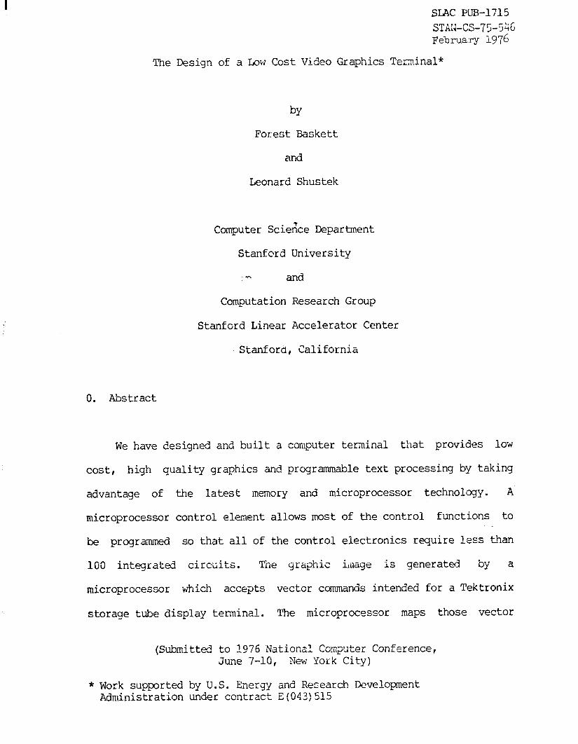
0. Abstract
We have designed and built a computer terminal that provides low
cost, high quality graphics and programmable text processing by taking
advantage of the latest memory and microprocessor technology. A
microprocessor control element allows most of the control functions to
be programmed so that all of the control electronics require less than
100 integrated circuits. Tne graphic illlage is generated by a
microprocessor which accepts vector ccmmands intended for a Tektronix
storage tube display terminal. The microprocessor maps those vector
(Submitted to 1976 I\lationsl Computer Conference, June 7-10, New York City)
* Work supported by U.S. Energy and Research Development Administration under ccntract E(043)515

commands into a random access memory, and the resulting bit map of the
graphic image is displayed on a standard TV- monitor. Reasonable
resolution in the graphic image requires a large number of bits in the
bit map, but with the use of 4K memory chips, less than 100 integrated
circuits are required for the bit map memory in our design. At 1975
small-quantity prices, the parts cost for the terminal is approximately
$2000.
1. Introduction
The desirability of low cost graphics for many kinds of scientific
and ~engineering computations is reflected in the sucess of the small
Tektronix storage tube computer terminals. Our experience with that
type of terminal, the 4013 in particular, led to a project to overcome
the limitations of the storage tube technology for low cost graphics in
a convenient terminal format. We have designed and built a computer
terminal that uses a microprocessor for control, a random access memory
for image storage, and a standard TL7 monitor for display. This choice
of recently available technology results in a terminal with high
reliability, low maintenance, and expanded capability compared to the
storage tube graphics terminal. In tests, it has been favorably
received by many users. Approximately 200 integrated circuits are used
for the electronics and the total parts cost for the terminal (in small
quantity prices, in late 1975) was approximately $2000. Kuch of the
cost of the terminal is the the electronics and we foresee substantial
-2-

price reductions in the near future, especially in large quantity
purchases.
The image quality of the graphics is comparable to that obtainable
on small storag- 0 tubes such as those used in the Tektronix 4010-series
terminals. Because the graphic image is maintained in random access
read/write memory, the image can be selectively erased, a capability not
easily obtained with a storage tube. By using the graphic image memory
to store character codes for a character generator, we obtain a text
mode that is capable of storing 600 8&character lines of typescript.
This overcomes some of thhe traditional objections to "soft copy"
terminals. Since the typescript is managed by a programmable processor,
the text processing capabilities of the terminal are very general. It
is easy to eliminate annoying aspects of text terminals and to adapt the
terminal to the needs of the computers to which it. is connected and to
the needs of its users. In fact, many of the irritating aspects of the
terminal interface of computing systems can be masked by suitably
programming the terminal. For example, the limitation to half-duplex of
our IEM computing system is especially annoying for experiencti users
when response time is slow. We therefore programmed the terminal to
buffer lines of keyboard input and send them to the computer at the
appropriate times. With the increasing difficulty of modifying system
software, this local masking could be a major benefit to many users.
The terminal has three 128-character character generators. One is
a read-only memory containing an extended ASCII character set, and the
other two are read/write memories for user-programmable character sets.
-3-
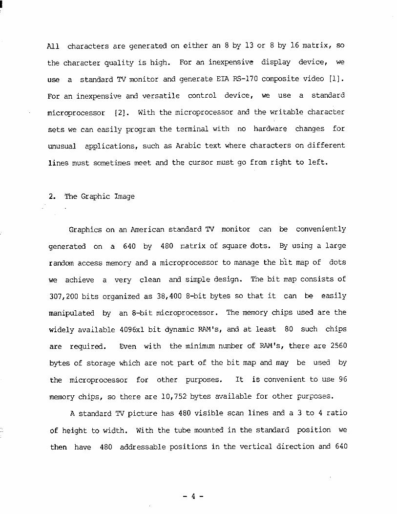
All characters are generated on either an 8 by 13 or 8 by 16 matrix, so
the character quality is high. For an inexpensive display device, we
use a standard TV monitor and generate EIA RS-170 composite video [l].
For an inexpensive and versatile control device, we use a standard
microprocessor [2]. With the microprocessor and the writable character
sets we can easily program the terminal with no hardware changes for
unusual applications, such as Arabic text where characters on different
lines must sometimes meet and the cursor must go from right to left.
2. The Graphic Image
Graphics on an American standard TV monitor can be conveniently
generated on a 640 by 480 matrix of square dots. By using a large
random access memory and a microprocessor to manage the bit map of dots
we achieve a very clean and simple design. The bit map consists of
307,200 bits organized as 38,400 8-bit bytes so that it can be easily
manipulated by an 8ai.t microprocessor. The memory chips used are the
widely available 4096x1 bit dynamic RAM's, and at least 80 such chips
are required. Even with the minimum number of RAM's, there are 2560
bytes of storage which are not part of the bit map and may be used by
the microprocessor for other purposes. It is convenient to use 96
memory chips, so there are 10,752 bytes available for other purposes.
A standard TV picture has 480 visible scan lines and a 3 to 4 ratio
of height to width. With the tube mounted in the standard position we
then have 480 addressable positions in the vertical direction and 640
-4-

addressable positions in the horizontal direction. Using all 480 scan
lines for different video information requires that the alternate-frame
interlace feature be correctly implemented. Many text-only TV terminals
are simplified by generating the same information in both the even and
odd frames, and adjusting the timing so that the scan lines are not
interlaced. The result is at most 24 lines of text with low image
quality and a screen refresh rate of 60 hertz instead of the normal TV
standard of 30 hertz. The higher refresh rate is desirable because the
standard P4 phosphor appears to flicker badly when high contrast images
are displayed and refreshed at 30 hertz. In contrast to that approach, .TI our ~terminal uses full interlace to get more text and higher quality
text and graphics, and compensates for the 30 hertz refresh rate by
using a TV monitor with a green P39 long persistence phosphor. The P40
long persistence phosphor with black images on a white background also
seems acceptable.
The 640 by 480 matrix of addressable points of the graphic image is
almost exactly five eighths of the 1024 by 780 matrix of visible points
on the small Tektronix graphics terminals (models 4006, 4010, 4012, and
4013). Thus we can accept line drawing commands designed for those
terminals, scale the coordinates by five eighths (two shifts and an
add) I and display the expected picture. The resolution of the image -is
not quite as good, but otir superior image contrast seems to more than
ccmpensate for the slight loss of resolution. Figures 1 and 2 are
photographs taken from the TV monitor which show typical images created
from Tektronix graphic commands.

Progressive Sophisticatiorl 31 Chrac&r sets
+ = Spline x - Splice
Intqmhticm Smcmthing
FIGTJRF: 1. Photograph of a Cra@Cc Image on the TV 3ionitor
-6-

-4
0 .
0

3. Text Mode
In text mode, the display image memory is no longer a bit map of
what is displayed on the screen but instead is a coded representation of
the text that should be displayed. An 8 bit code permits up to 256
different characters to be displayed at one time. The terminal allows
the user (or the computer) to select any two of the three 128-character
character sets to be active when the terminal is in text mode. By
storing a character code instead of an image of the character, we reduce
-the 'amount of memory necessary for a screen image by a factor of 13.
The large amount of extra memory thus made available is used to keep a
long record of the typescript of a terminal session, and "local
commands" (key strokes intercepted by the microprocessor) allow the user
to scroll backward and forward through this tpscript. The
microprocessor can easily implement a variety of scrollinq modes. We
currently have three such modes. One is a "page-turning" mode where a
page is one screen (37 lines) of text and successive pages overlap by
five lines. Another is a high speed mode that allows the user to
rapidly scan the entire 600 lines of text that can be in the locally
stored typescript. The third mode is a slow, smooth scrolling that
allows the text to be read comfortably as it moves.
4. Hardware Organization
-8-

I
As in many graphics terminals, it is convenient to think of the
electronics as two processors, a display processor and a control
processor. Figures 3 and 4 are block diagrams of the two processors.
The control processor is an 8 bit microprocessor, the Intel 8080 [2].
The display processor is a simple collection of counting registers and
random logic which we call the video generator. The video generator has
read-only access to the 48K bytes of graphic image memory. It receives
an initial display address from the mTcroprocessor during the vertical
retrace of the TV monitor. It then fetches successive bytes beginning
from the initial display add-ress and uses those bytes to generate the
video image for the current display frame. Vhen the terminal is in
qr aphics mode, the 8 bits from the memory are used directly for the
intensity information for one eightieth of a raster line (640/8 = 80).
When the terminal is in text mode, the 8 bits from the memory
together with 4 bits of character row address (maintained by the video
generator) are used to address one of the character generators which
then supplies eight bits of intensity information for a segment of the .
raster line. This fetching, decoding (if necessaryj, and displaying of
each segment of the raster line is pipelined by the video generator
because of the timing reguirements of the TV monitor and the relatively l
slow speed of the memories used. One eightieth of a raster line must-be
displayed in 650 nanoseconds, but the access time of the memory chip is
4 20 nanoseconds. Thus the eight bit organization and the speed of the
memory fit nicely with the ‘speed requirements of the video generator.
The memory chips used in the terminal have a read cycle time of 700
-9-

I
CLOCK 18 MHz 0 GENERATOR
(8224) 8 BIT CPU (8080Aj
+ - CONTROL
3 :PU DATA BUS
8K BYTE PROM
(2708’s) t-
-I 128 BYTE I- ) STATIC RAM 1
16 CPU ADDRESS BUS
4 ’ 7 USART , / EIA (8251) / RS232
FIGUREi 3. VGT Control Processor
- 10 -

CPU DATA BUS CPU ADDRESS BUS
DYNAMIC RAM
CHAR ADDR
16 /’ f s-
ADDR 16 l i
/ 7
I DATA OUT
COUNTER
ADDR
DATA IN 4K BYTE 2K BYTE I \ / + STATIC RAM ROM
CHARACTER GEN CHARACTER GEN A
DATA OUT DATA OUT
INTERLACE SYNC 8 GENERATOR A’
t SHIFT REG
1
8 1 CPU DATA BUS 8
/’ /’
v l SHIFT REG SHIFT REG
I
COMPOSITE VIDEO TO MONITOR
FIGURE 4. VGT Display Processor
- 11 -
nanoseconds and are dynamic. We must therefore provide for some form of
interleaving to prevent consecutive accesses to individual chips, and
memory refresh to prevent the loss of information. The memory is
organized into three banks of 16K bytes each and the low order address
bit is used to choose between two of the three banks so that an access
is possible every 650 nanoseconds. The internal construction of the
memory chips is such that 64 bits are simultaneously refreshed when the
chip is addressed even if the output is not enabled. By addressing two
of the three banks for every sixth or seventh raster line of 80 accesses
the video generator can refresh the entire memory at the required rate
-(once every two milliseconds) with almost no extra hardware or loss of
memory cycles. w not refreshing the memories much more often than is
required, power dissipation and therefore heat generation is kept to a
minimum.
The read-only character generator is an 8192-bit read-only memory
chip organized as 128 64-bit characters. The characters are formed on a
7 by 9 bit matrix and the remaining bit of the 64 determines whether the
character is to be descended an extra 3 raster lines ("g", for example).
-Thus this character generator displays dots on a 7 by 12 submatrix of
our 8 by 13 field. The maximum access time of this chip is 500
nanoseconds so that if fits easily into the 650 nanosecond pipeline
window. The writeable character set is constructed from eight 4096-bit
static memory chips, which allows 256 different characters each on an 8
by 16 matrix. Thus when this character generator is used with our 8 by
13 field, an 8 by 3 submatrix is discarded. These memories have a 400
- 12 -

nanosecond cycle time so that they, too, fit in the pipeline window.
Static memory chips, though more expensive than the dynamic chips used
for the bit map, are used for the writeable character sets because there
is no simple way to guarantee the automatic refresh that dynamic chips
require.
Putting a character 7 bits wide into an 8 bit field means that
characters are separated by one bit of space. In practice we have found
that one bit of space does not give the most visually pleasing text so
the bits for a character are shifted finto the eight bit field slightly
faster than the bits of a graph. In essence, seven bits of a character
are squeezed into a six bit Yield so that two bits are left between
characters. Our experiments indicate that this gives the best visual
ef feet. For the writable character generator, either the shifting rate
of the read only character generator or the shifting rate of graphics
can be used. Shifting the bits int.o the 8 bit field slightly faster
than the graphic rate provides an extra bit of space for characters that
should be well separated, and shifting the bits into the field at the
graphic rate allows characters that are supposed to merge at their
boundaries to do so. The control processor can set which of the bit
clocks will be used for the writable characters (for the entire screen).
The read-only character generator puts dots on as many as twelve
different raster lines because some of the g-bit high characters are
descended 3 raster lines. Character lines are displayed in thirteen
raster lines to insure that there is always at least one completely
blank raster line between them. Although this would be too little
- 13 -

separation if all text characters were 12 bits high, it is visually
pleasing since the average separation is four raster lines for upper m
case and six raster lines for lower case. The appearance is not one of
double spacing as in many video terminals, and it allows 37 lines of
text to be on the screen. Since the writable character generators can
provide information on as many as 16 raster lines, the control processor
can change the number of raster lines per text line from 13 to 16. The
result is more space for a text line and fewer (30) text lines per
screen. This is desirable for character sets containing mathematical or
drawing symbols, or for normal characters with diacritic marks.
The character row address counter starts at an initial value
supplied by the control processor during the vertical retrace. Thus the
first raster line of the screen may be the nth row of a text line where
n is greater than one. This shifts the entire screen up by n-l raster
lines, and allows the text to be scrolled up (or down) one raster line
at a time. The rate at which this smooth scrolling is done is
controlled by the microprocessor, and at a well chosen rate the text can
be read comfortably as it moves.
Figures 5 and 6 are photographs of our prototype video graphics
terminal. A single lightweight unit (19 lbs) contains the keyboard,
power supplies, and all electronics; the separate standard TV monitor is
a commercially available unit. The three small printed circuit boards
contain only the 48K byte display memory, and the larger wire wrapped
board contains the microprocessor, the program and character set memory,
the serial interface, and all control logic.
- 14 -

The Video Graphics Terminal prototype with the top cover removed
.
*

FIGURE! 6. The Video Graphics Tekuinal with the control electronics up and the memory
boards below
- 16-

5. Software Organization
The overall design philosophy required the control processor
software to be responsible for as many functions of the terminal as
possible. The display address, the display format, the keyboard, and
the communications interface are all controlled by the microprocessor.
The processor accepts a single interrupt generated by either the t
communications interface or the video generator. The communications
interface generates an interrupt when a new character arrives or when a
character has completed trangission. The video generator causes an
interrupt at the bottom of a frame, indicating that vertical retrace is
occuring.
For interrupts caused by the video generator, the processor must
send a new display address and an initial row number for the first line
of text to the video generator for the next video frame. The display
address or the initial row number can be adjusted from their previous
values if the video image is to be scrolled. In addition to sending the
display address to the video generator, the processor polls the keyboard
to see if a new key has been struck or to see if the previous key is
still depressed; polling the keyboard at 6G hertz is fast enough for
even the fastest typists. Timing is done by counting vertical retrace
interrupts, which gives the processor a 60 hertz line frequency clock.
The clock is used for timing such things as the scrolling rate, the
cursor blink rate, and the keyboard repeat delay and rate. If a key is
- 17 -

held down for two fifths of a second., the processor starts repeating
that key at a 20 hertz rate. This seems to be as fast as a key can be * repeated and still allow the typist to stop at a predetermined place on
the line. The character repeat rate and typing rate can be faster than
the line (baud) rate of the communications interface because the
microprocessor buffers characters for transmission.
Since the software of the microprocessor controls the display
format and the communications interface, many combinations of local and
remote editing are possible. Business oriented features such as
protected fields and block transmission could be handled in a
-straightforward manner by the local software.
Local software is stored in 1024x8-bit erasable programable
read-only memory chips (Intel 2708 EPROMs). These chips are so easily
programmed that we have considered building the programmer into the
terminal. The terminal could then be instructed to accept coded binary aA
text from the remote computer to rewrite the PROM plugged into the
programming slot.
The software is written in assembly language. The assembly
language we use is a more elegant and powerful one than that provided by
the microcomputer manufacturer, and was easily implemented using
Assembler language mapping macros on our large computer. Software in
the terminal for local text editing is still under development, but the
software that handles si,mple character mode transmission, scrolling, and
graphics (a 4013 simulator) is complete and requires only 2000 bytes of
read-only memory (two PRcMs). Local text editing is a nontrivial
- 18 -

,problem, and we expect to use another 2000 bytes for a line editor and
more sophisticated typescript management. We have allowed space for
8192 bytes of read-only memory. If we implement features, such as those
described by Gerhart and Parnas [3], that take advantage of the high
display speeds that are possible and the essentially random
addressability of the display screen, we could use most of that program
storage.
The display memory is logicallytdivided into 600 sequential lines
of 80 bytes each. Our current system does not use a linked list
structure. The linked li$t structure such as that used by the
Hewlett-Packard video terminals [4] has advantages such as minimizing
storage usage and manipulating the typescript with simple changes to a
few link fields. With a large amount of storage, however, its
economical use is not an overriding concern. With the simple linear
storage layout, the local software is very straightforward. Some
operations can be time consuming but our experience has shown that these
operations are infrequent so that some inefficiency can be tolerated.
Linked structures are disadvantageous because it becomes difficult to
quantify the time required for certain common operations such as
inserting a character in a line. For our memory organization, it would
not be a simple matter to insure memory refresh with a linked list
organization. One desirable feature we could add if we were to use a
linked list structure would be an ability to display bands of the screen
in either graphics mode or in character mode.
- 19 -

6. Local Processing Speed c We have run our graphics software at a serial interface speed of
2400 baud (240 characters per second) and have had no trouble keeping up
with incoming graphic commands at that rate, but it is possible that we
could not keep up with a higher line speed in graphics mode because of a
memory accessing limitation we have placed on the microprocessor. We
currently do not allow the microprocessor to access the graphic image
memory while a scan line is being generated by the video generator. The
memory is slow enough and simple enough so that if the microprocessor
- steals a memory cycle during the generation of a scan line, the
interference results in annoying “snow” on the screen. With the
limitation, the microprocessor is able to ‘access the graphic image
memory only during the horizontal retrace (one or two acceses) and
during the vertical retrace (hundreds of acceses). Vector drawing
commands from the communication line at a rate greater than 240 per
second could require more graphic image accesses than we can deliver
with the “no snow” limitation. However, it is easy to remove this
restriction and we have made it subject to control by the
microprocessor. For example, in order to erase the screen as rapidly as
possible, the microprocessor first enables accesses during scan line
generation, erases all the memory byte by byte, and then disables-such
cycle stealing. Thus the screen erase is snowy but fast.
For the storag,. = of local variables and the subroutine stack, the
microprocessor has immediate access to a small 128-byte random access
- 20 -

memory. This small memory is not part of the bit map memory accessed by
the video generator and is tkius always available to the microprocessor.
7. costs
The most expensive component of the video graphics terminal is the
random access memory used for the graphic image. Buying 100 chips of
the type we use (according to the September 1975 list price) will cost
$1250. Iarge customer discounts would bring the price down to $800.
Price reductions anticipated for 1976 will bring the cost down further -T-= to $400. We presume that the 16K bit memory chips will eventually make
the memory cost even lower. At that point the cost of the memory
balances nicely with the cost of the other components of the terminal,
since keyboards cost between $100 and $300 and TV monitors cost between
$100 and $300. The most expensive single chip we use is the
microprocessor, which can now be purchased for $40. There are five
other LSI chips used that cost approximately $15 each. The PROM memory
chips for program storage are new devices and currently sell for $96,
but the cost is expected to drop when there are multiple sources early
in 1976. Nevertheless, using current list prices, the parts cost for
the terminal is approximately $2000. Since most of the cost is in-the
electronics where price reductions are expected rather than in
components like storage tubes where price increases are more likely, we
expect that future low cost graphic systems will use this approach.
- 21 -

I
8. Alternative Approaches
. With existing technology, the principal alternative approach that
seems feasible is the use of charge-coupled devices (CCD's) rather than
a random-access memory to store the bit map of the graphic image. The
CCD's seem to be ideally suited to the needs of the video generator,
which requires only sequential access to the bit map image. However,
they are far from ideally suited to the needs of the graphic image
generator in the microprocessor, which accepts commands from the
communications interface and must draw vectors between arbitrary points
- on the screen. The bit maF of the vector must be created quickly in the
graphic image memory so that the buffer holding incoming commands will
not overflow. Methods for simulating random access to sequential memory
devices can be devised, but they seem either complicated or slow. Thus
while CCD's are excellent video output devices, their organization is
not appropriate for a video input device of this type. E'urthermore, the
current and projected cost advantage of CCD's over RAM's does not seem
to justify the effort necessary to use them for this application.
9. Future Extensions
The next obvious step in the-develoment of a terminal of this type
is the use of a 16 bit microprocessor that addresses 16 bit words (not
bytes) together with a memory 16 bits wide. This would double the
number of bits that could be addressed easily, it would double the
- 22 -

effective memory bandwidth, and it would substantially increase the
computational power of the local processor. With such a change, we
could perhaps provide higher speed and higher resolution graphics,
multiple graphic images, more text storage, and more sophisticated local
processing. However, note that using color or gray scale would each +
multiply the memory size and bandwidth requirements by at least a factor
of two. : '
'It is tempting to move in the 'direction of the smaller T
minicomputers and to add a variety of peripheral devices controlled by
the local'processor. A. very useful and easy addition would be a _. 7--
mechanism for locating a point on the screen, such as a lightpen or
hand-held "mouse". The addition of a floppy disk or small tape drive
would encourage the development of a more sophisticated local .
screen-oriented text editor', of a local file system, and of a more
general a&flexible local operating system. .a..
10. 'Summary
We have designed and constructed a low cost graphics terminal based
on a TV monitor, a microprocessor control, and a random access memory
defining a graphics bit map. The single-unit parts cost for this
terminal is less than $2000. The most expensive components in the
terminal are those that are most likely to become less expensive in the
near future. Because of the microprocessor the terminal is very
flexible, and it was easy to program it to be software compatible with
- 23 -

Tektronix storage tube terminals. It is also easy to provide extensive
text processing capabilities. This design is_simple and inexpensive
because of technology introduced in the last two years. This approach
premises to be even more competitive with other methods as this
technology matures.
11. Acknowledgements
We have been ably assisted by Edward H. Frank in the development
of the software for the microprocessor. We thank Intel Corporation for
- the-donation of some of the parts for this terminal. Figures 1 and 2
were produced by the DISSPLA graphics software system from Integrated
Software Systems Corporation of San Diego, California. This work has
been partially supported by the Energy Research and Development
Administration under contract E(043)515.
12. References
1. Electronic Industries Association, "Electrical Performance
Standards-Monochrome Television Studio Facilities", RS-170,
November, 1957.
2. Intel Corporation, "Intel 8080 Microcomputer Systems User's
Manual", September, 1975.
3. Gerhardt, D. and Parnas, D.L., "Window: A formally- specified
graphics based text editor", Carnegie Mellon University
Computer Science Dept., 1973
4. Hewlett-Packard Journal, Vol. 26, No. 10, June, 1975
- 24 -