Embed Size (px)
Citation preview

SI1000 SERIES DISPLAY UNIT
user and installation manual
Index 502893 issue 4
IndexSection Title Page
1.0 Safety Summary . . . . . . . . . . . . . . . . . . . . . . . . . . . . . . . . . . . . . . . . . . . . . 22.0 Service and Repair . . . . . . . . . . . . . . . . . . . . . . . . . . . . . . . . . . . . . . . . . . . 33.0 Installation into a Panel. . . . . . . . . . . . . . . . . . . . . . . . . . . . . . . . . . . . . . . . 44.0 General Description . . . . . . . . . . . . . . . . . . . . . . . . . . . . . . . . . . . . . . . . . . 64.1 Overview . . . . . . . . . . . . . . . . . . . . . . . . . . . . . . . . . . . . . . . . . . . . . . . . . . . 64.2 Specification . . . . . . . . . . . . . . . . . . . . . . . . . . . . . . . . . . . . . . . . . . . . . . . . 65.0 Display Panel and Connections . . . . . . . . . . . . . . . . . . . . . . . . . . . . . . . . . 75.1 Front and Rear Panel Layouts . . . . . . . . . . . . . . . . . . . . . . . . . . . . . . . . . . 75.1.1 Layout of Rear Panel SI1500 . . . . . . . . . . . . . . . . . . . . . . . . . . . . . . . . . . . 85.1.2 Layout of Rear Panel SI1300 . . . . . . . . . . . . . . . . . . . . . . . . . . . . . . . . . . . 85.1.3 Layout of Rear Panel SI1100 . . . . . . . . . . . . . . . . . . . . . . . . . . . . . . . . . . . 95.2 Connection Details . . . . . . . . . . . . . . . . . . . . . . . . . . . . . . . . . . . . . . . . . . .106.0 Set up Options . . . . . . . . . . . . . . . . . . . . . . . . . . . . . . . . . . . . . . . . . . . . . .136.1 Main Menu Overview . . . . . . . . . . . . . . . . . . . . . . . . . . . . . . . . . . . . . . . . .136.2 Menu Setup Detail . . . . . . . . . . . . . . . . . . . . . . . . . . . . . . . . . . . . . . . . . . .166.3 Calibration Menu. . . . . . . . . . . . . . . . . . . . . . . . . . . . . . . . . . . . . . . . . . . . .196.3.1 Set the Maximum Reading to the Maximum Sensor Output . . . . . . . . . . .196.3.2 Set the Minimum Reading to the Minimum Sensor Output . . . . . . . . . . . .206.3.3 Calibrate the Maximum and Minimum . . . . . . . . . . . . . . . . . . . . . . . . . . . .217.0 Functions. . . . . . . . . . . . . . . . . . . . . . . . . . . . . . . . . . . . . . . . . . . . . . . . . . .227.1 Zero Function . . . . . . . . . . . . . . . . . . . . . . . . . . . . . . . . . . . . . . . . . . . . . . .227.2 Hold Function . . . . . . . . . . . . . . . . . . . . . . . . . . . . . . . . . . . . . . . . . . . . . . .227.3 Peak Function . . . . . . . . . . . . . . . . . . . . . . . . . . . . . . . . . . . . . . . . . . . . . . .237.4 Input Relays . . . . . . . . . . . . . . . . . . . . . . . . . . . . . . . . . . . . . . . . . . . . . . . .248.0 Communication Protocol. . . . . . . . . . . . . . . . . . . . . . . . . . . . . . . . . . . . . . .25Appendix A Units Supplied with Power Supply . . . . . . . . . . . . . . . . . . . . . . . . . . . . . . .27
Return Of Goods Solartron Sales Offices
1
502893 issue 4
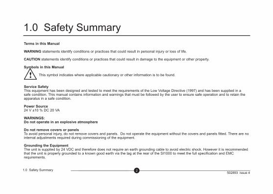
Terms in this Manual
WARNING statements identify conditions or practices that could result in personal injury or loss of life.
CAUTION statements identify conditions or practices that could result in damage to the equipment or other property.
Symbols in this Manual
This symbol indicates where applicable cautionary or other information is to be found.
Service Safety This equipment has been designed and tested to meet the requirements of the Low Voltage Directive (1997) and has been supplied in a safe condition. This manual contains information and warnings that must be followed by the user to ensure safe operation and to retain the apparatus in a safe condition.
Power Source 24 V ±10 % DC 20 VA
WARNINGS:Do not operate in an explosive atmosphere
Do not remove covers or panels To avoid personal injury, do not remove covers and panels. Do not operate the equipment without the covers and panels fitted. There are no internal adjustments required during commissioning of the equipment.
Grounding the Equipment The unit is supplied by 24 VDC and therefore does not require an earth grounding cable to avoid electric shock. However it is recommended that the unit is properly grounded to a known good earth via the tag at the rear of the SI1000 to meet the full specification and EMC requirements.
2
1.0 Safety Summary
1.0 Safety Summary
502893 issue 43
This equipment contains no user serviceable parts.
This equipment must be returned to your Solartron dealer for any service and repair.
The SI1000 is designed to be maintenance free.
Contact with solvents should be avoided.
Any attempt to dismantle any of the SI1000 will invalidate the warranty. The SI1000 series are precision instruments and should be handled with care.
2.0 Service and Repair
2.0 Service and Repair
502893 issue 44
3.0 Installation into a Panel
3.0 Installation into a Panel
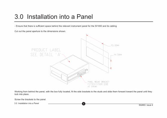
- Ensure that there is sufficient space behind the relevant instrument panel for the SI1000 and its cabling
Cut out the panel aperture to the dimensions shown.
Working from behind the panel, with the box fully located, fit the side brackets to the studs and slide them forward toward the panel until they lock into place.
Screw the brackets to the panel.
502893 issue 45
3.0 Installation into a Panel (cont)
3.0 Installation into a Panel (cont)
CAUTION: Do not over tighten the screws as this may damage the case of the instrument.
WARNING: On installing or removing the SI1000, you must be aware of any hazardous equipment or materials in the vicinity. Make sure that any equipment into which the SI1000 system is to be installed is switched off and made safe.
CAUTION: Avoid installing the SI1000 close to switch gear, contactors or motor starters.
CAUTION: Do not place other signal and power supply wiring in the same loom as the SI1000 wiring.
CAUTION: Use screened cables for all leads, with the screen earthed at one end only.
502893 issue 46
4.0 General Description
4.0 General Description
4.1 OVERVIEW
The SI1000 series of readouts provides a simple way of using Solartron transducers. All of the basic metrology functions are provided within this small robust instrument.
4.2 SPECIFICATION
See the Product data Sheet 502892
502893 issue 47
5.0 Display Panel and Connections
5.0 Display Panel and Connections
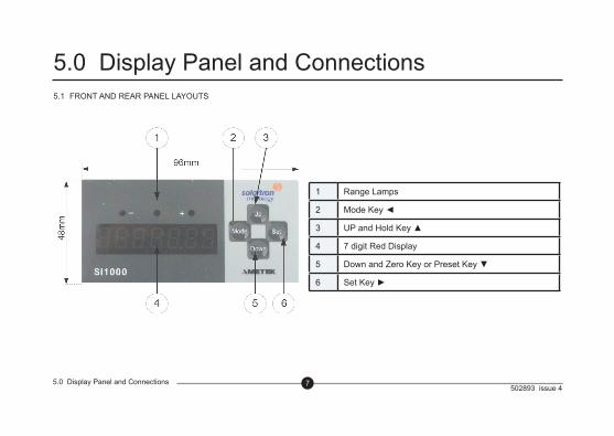
5.1 FRONT AND REAR PANEL LAYOUTS
1 Range Lamps
2 Mode Key ◄
3 UP and Hold Key ▲
4 7 digit Red Display
5 Down and Zero Key or Preset Key ▼
6 Set Key ►
502893 issue 48
5.0 Display Panel and Connections (cont)
5.0 Display Panel and Connections
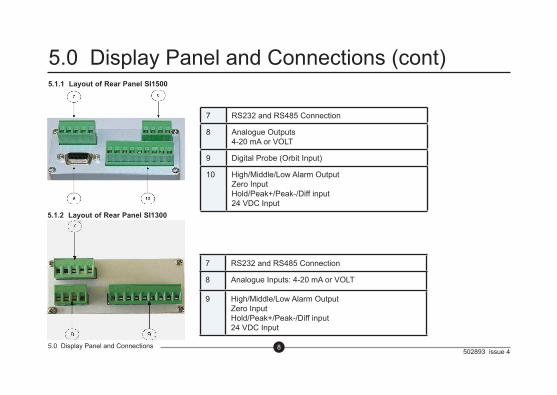
5.1.1 Layout of Rear Panel SI1500
7 RS232 and RS485 Connection
8 Analogue Outputs4-20 mA or VOLT
9 Digital Probe (Orbit Input)
10 High/Middle/Low Alarm OutputZero InputHold/Peak+/Peak-/Diff input24 VDC Input
5.1.2 Layout of Rear Panel SI1300
7 RS232 and RS485 Connection
8 Analogue Inputs: 4-20 mA or VOLT
9 High/Middle/Low Alarm OutputZero InputHold/Peak+/Peak-/Diff input24 VDC Input
502893 issue 49
5.0 Display Panel and Connections (cont)
5.0 Display Panel and Connections
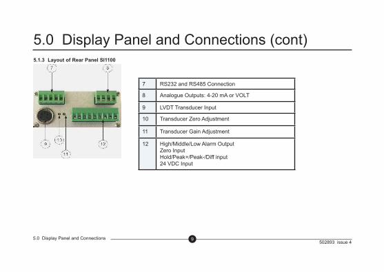
5.1.3 Layout of Rear Panel SI1100
7 RS232 and RS485 Connection
8 Analogue Outputs: 4-20 mA or VOLT
9 LVDT Transducer Input
10 Transducer Zero Adjustment
11 Transducer Gain Adjustment
12 High/Middle/Low Alarm OutputZero InputHold/Peak+/Peak-/Diff input24 VDC Input
502893 issue 410
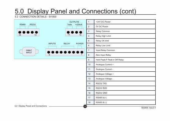
5.0 Display Panel and Connections (cont)5.2 CONNECTION DETAILS - SI1500
5.0 Display Panel and Connections
18 1014 13
ORBITINPUT
19
RS485 RS232 Volts 4-20mAOUTPUTS
RELAY POWERINPUTS
1 +24V DC Power
2 0V DC Power
3 Relay Common
4 Relay High Limit
5 Relay OK limit
6 Relay Low Limit
7 Input Relay Common
8 Zero Input Relay
9 Hold Peak-P Peak-n Diff Relay
10 Analogue Current +
11 Analogue Current -
12 Analogue Voltage +
13 Analogue Voltage -
14 RS232 TXD
15 RS232 RXD
16 RS232 GND
17 RS485 A(+)
18 RS485 B (-)
502893 issue 4115.0 Display Panel and Connections
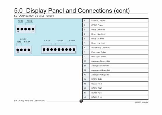
5.0 Display Panel and Connections (cont)5.2 CONNECTION DETAILS - SI1300
18 14
9 1
R S485 R S 232
V olts R E LA Y P O W E RIN P U TS4-20 m AIN P U TS
1013
1 +24V DC Power
2 0V DC Power
3 Relay Common
4 Relay High Limit
5 Relay OK limit
6 Relay Low Limit
7 Input Relay Common
8 Zero Input Relay
9 Hold Input Relay
10 Analogue Current IN+
11 Analogue Current IN-
12 Analogue Voltage IN+
13 Analogue Voltage IN-
14 RS232 TXD
15 RS232 RXD
16 RS232 GND
17 RS485 A(+)
18 RS485 B (-)
502893 issue 4125.0 Display Panel and Connections
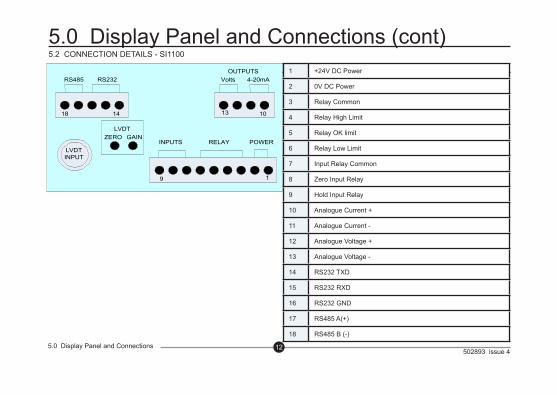
5.0 Display Panel and Connections (cont)5.2 CONNECTION DETAILS - SI1100
18 1014 13
19
RS485 RS232 Volts 4-20mAOUTPUTS
RELAY POWERINPUTSZERO GAIN
LVDT
LVDTINPUT
1 +24V DC Power
2 0V DC Power
3 Relay Common
4 Relay High Limit
5 Relay OK limit
6 Relay Low Limit
7 Input Relay Common
8 Zero Input Relay
9 Hold Input Relay
10 Analogue Current +
11 Analogue Current -
12 Analogue Voltage +
13 Analogue Voltage -
14 RS232 TXD
15 RS232 RXD
16 RS232 GND
17 RS485 A(+)
18 RS485 B (-)
502893 issue 4136.0 Set Up Options
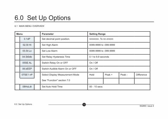
6.0 Set Up Options6.1 MAIN MENU OVERVIEW
Menu Parameter Setting Range
0.1dP Set decimal point position. nnnnnnn. To nn.nnnnn
02.St Hi Set High Alarm 0099.9999 to -099.9999
03.St Lo Set Low Alarm 0099.9999 to -099.9999
04.St0db Set Relay Hysteresis Time 0.1 to 9,9 seconds
05SE AL Switch Relay On or OFF On / Off
06.bEEP Switch Audible Alarm On or OFF On / Off
07SE1 nP Select Display Measurement Mode
See "Function" section 7.0
Hold Peak + Peak - Difference
08HoLdt Set Auto Hold Time 00 - 10 secs
502893 issue 4146.0 Set Up Options
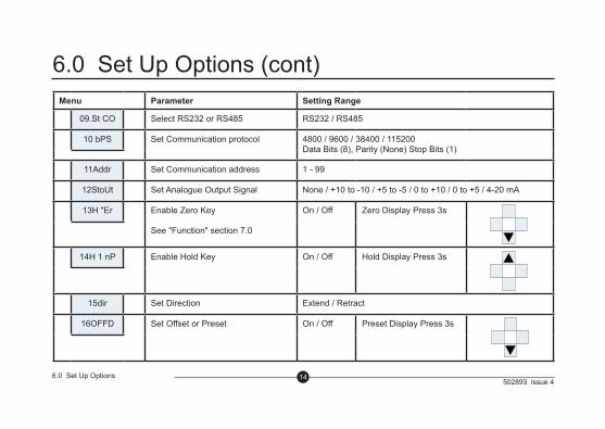
6.0 Set Up Options (cont)Menu Parameter Setting Range
09.St CO Select RS232 or RS485 RS232 / RS485
10 bPS Set Communication protocol 4800 / 9600 / 38400 / 115200Data Bits (8), Parity (None) Stop Bits (1)
11Addr Set Communication address 1 - 99
12StoUt Set Analogue Output Signal None / +10 to -10 / +5 to -5 / 0 to +10 / 0 to +5 / 4-20 mA
13H "Er Enable Zero Key
See "Function" section 7.0
On / Off Zero Display Press 3s
14H 1 nP Enable Hold Key On / Off Hold Display Press 3s
15dir Set Direction Extend / Retract
16OFFD Set Offset or Preset On / Off Preset Display Press 3s
502893 issue 4156.0 Set Up Options
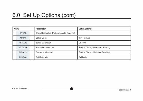
6.0 Set Up Options (cont)
Menu Parameter Setting Range
17rEAL Show Real value (Probe absolute Reading)
18Unit Select Units mm / inches
19StAn9 Select calibration On / Off
20CAL HI Set Scale maximum Set the Display Maximum Reading
21CALLo Set scale minimum Set the Display Minimum Reading
22ACAL Set Calibration Calibrate
502893 issue 4166.0 Set Up Options
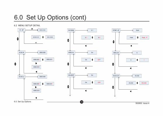
6.0 Set Up Options (cont)6.2 MENU SETUP DETAIL
01. dP nnnn.nnn
nnnnn.nn nnn.nnnn
02.St Hi 0000.000
0000.000 0000.001
R
0000.000
03.St Lo 0000.000
0000.000 0000.001
R
0000.000
04.St0db 0.1
0.1 0.2
05SE AL On
On OFF
06.bEEP On
On OFF
07SE1 nP Hold
Hold Peak - P
09.St CO rS-232
rS-232 RS-485
08Ho ldt 0
0 1
502893 issue 4176.0 Set Up Options
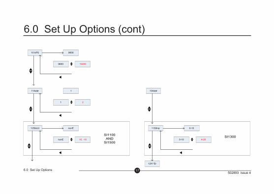
6.0 Set Up Options (cont)
11Addr 1
1 2
12StoUt nonE
nonE 10. -10
SI1100AND
SI1500
11StInp 0-10
0-10 4-20SI1300
12H “Er
10Addr
10 bPS 9600
9600 19200
502893 issue 4186.0 Set Up Options
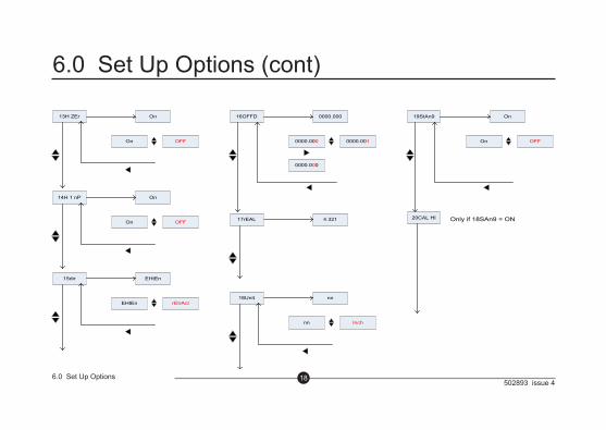
6.0 Set Up Options (cont)
13H ZEr On
On OFF
14H 1 nP On
On OFF
15dir EHtEn
EHtEn rEtrAct
16OFFD 0000.000
0000.000 0000.001
0000.000
17rEAL 4.321
18Unit nn
nn Inch
19StAn9 On
On OFF
20CAL HI Only if 18SAn9 = ON
502893 issue 4196.0 Set Up Options
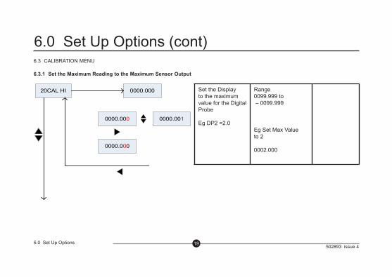
6.0 Set Up Options (cont)6.3 CALIBRATION MENU
6.3.1 Set the Maximum Reading to the Maximum Sensor Output
20CAL HI 0000.000
0000.000 0000.001
0000.000
Set the Display to the maximum value for the Digital Probe
Eg DP2 =2.0
Range0099.999 to – 0099.999
Eg Set Max Value to 2
0002.000
502893 issue 4206.0 Set Up Options
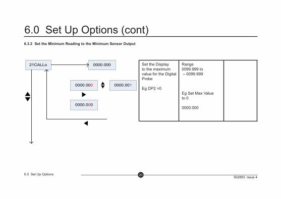
6.0 Set Up Options (cont)6.3.2 Set the Minimum Reading to the Minimum Sensor Output
21CALLo 0000.000
0000.000 0000.001
0000.000
Set the Display to the maximum value for the Digital Probe
Eg DP2 =0
Range0099.999 to – 0099.999
Eg Set Max Value to 0
0000.000

502893 issue 4216.0 Set Up Options
6.0 Set Up Options (cont)6.3.3 Calibrate the Maximum and Minimum
22ACAL H 1.000
H !.000 L 1000
H !.000
L 1000
01 dP
SWITCH BETWEEN HIGH AND LOW CALIBRATION POSITIONS
CALIBRATE HIGH POSITION (PROBE
IN)
SI1500: DP MAX COUNT=16383
H 16383
3 SECS TO SAVE CALIBRATION-BEEP
SI1100: LVDT VOLTAGE UP T0 +10
H 10000
CALIBRATE LOW POSITION (PROBE
OUT)
SI1500: DP MAX COUNT=16383
L 0000
SI1100: LVDT VOLTAGE UP T0 -10
L -10000
502893 issue 4227.0 Functions
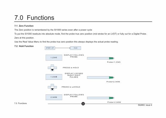
7.0 Functions7:1 Zero Function
The Zero position is remembered by the SI1000 series even after a power cycle
To put the SI1000 readouts into absolute mode, find the probe true zero position (mid stroke for an LVDT) or fully out for a Digital Probe.
Zero at this position.
Use the Real Value Menu to find the probe true zero position this always displays the actual probe reading.
7:2 Hold Function 07S E 1 nP H old
1 .2345D IS P LA Y FO LLO W S
P R O B E
P R E S S to H O LD
1.2345
D IS P LA Y LO C K E DR IG H T D IG IT
P U LS E S
P R E S S to unH O LD
2.3456D IS P LA Y FO LLO W S
P R O B E
P robe=1.2345
P robe=2 .3456
P robe=2.3456
502893 issue 4237.0 Functions
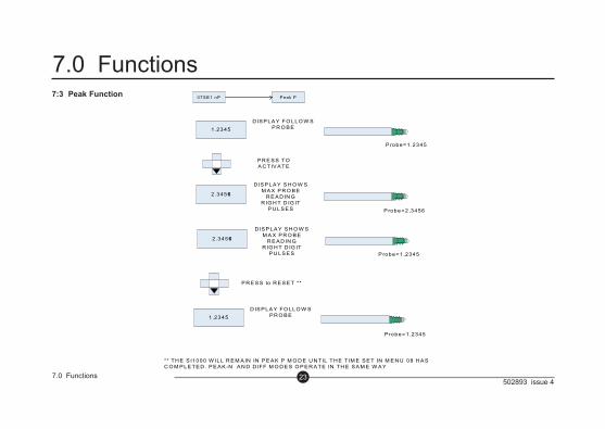
7.0 Functions7:3 Peak Function 07S E 1 nP P eak P
1 .2345D IS P LA Y FO LLO W S
P R O B E
P R E S S TO A C TIV A TE
2.3456
D IS P LA Y S H O W S M A X P R O B E
R E A D IN GR IG H T D IG IT
P U LS E S
P R E S S to R E S E T **
1 .2345D IS P LA Y FO LLO W S
P R O B E
P robe=1.2345
P robe=2.3456
P robe=1.2345
2.3456
D IS P LA Y S H O W S M A X P R O B E
R E A D IN GR IG H T D IG IT
P U LS E S P robe=1.2345
** TH E S I1000 W ILL R E M A IN IN P E A K P M O D E U N TIL TH E T IM E S E T IN M E N U 08 H A S C O M P LE TE D . P E A K -N A N D D IFF M O D E S O P E R A TE IN TH E S A M E W A Y
502893 issue 4247.0 Functions
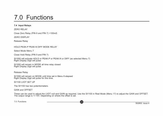
7.0 Functions7:4 Input Relays
ZERO RELAY
Close Zero Relay (PIN 8 and PIN 7) >100mS
ZERO DISPLAY
Release Relay
HOLD PEAK-P PEAK-N DIFF MODE RELAY
Select Mode Menu 7
Close Hold Relay (PIN 9 and PIN 7)
SI1000 will activate HOLD or PEAK-P or PEAK-N or DIFF (as selected Menu 7)Right Display Digit will pulse
SI1000 will remain in MODE all time relay closedRight Display Digit will pulse
Release Relay
SI1000 will remain on MODE until time set in Menu 8 elapsedRight Display Digit will pulse for this time.
SI1100 LVDT SET UP
The SI1100 has two potentiometers.
GAIN and OFFSET
These can be used to adjust the LVDT null and GAIN as required. Use the SI1100 in Real Mode (Menu 17) to adjust the GAIN and OFFSET. The output range is +/-10V. Depending on where the offset is set.
502893 issue 4258.0 Communication Protocol
(RS232 and RS485)
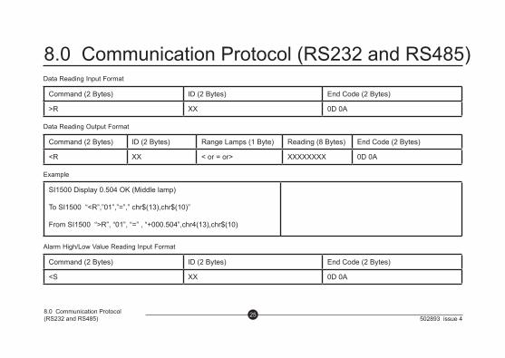
8.0 Communication Protocol (RS232 and RS485)Data Reading Input Format
Command (2 Bytes) ID (2 Bytes) End Code (2 Bytes)
>R XX 0D 0A
Data Reading Output Format
Command (2 Bytes) ID (2 Bytes) Range Lamps (1 Byte) Reading (8 Bytes) End Code (2 Bytes)
<R XX < or = or> XXXXXXXX 0D 0A
Example
SI1500 Display 0.504 OK (Middle lamp)
To SI1500 “<R”,”01”,”=”,” chr$(13),chr$(10)”
From SI1500 “>R”, “01”, “=” , “+000.504”,chr4(13),chr$(10)
Alarm High/Low Value Reading Input Format
Command (2 Bytes) ID (2 Bytes) End Code (2 Bytes)
<S XX 0D 0A
502893 issue 4268.0 Communication Protocol
(RS232 and RS485)
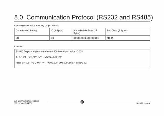
8.0 Communication Protocol (RS232 and RS485)Alarm High/Low Value Reading Output Format
Command (2 Bytes) ID (2 Bytes) Alarm Hi/Low Data (17 Bytes)
End Code (2 Bytes)
>S XX XXXXXXXX,XXXXXXXX 0D 0A
Example
SI1500 Display High Alarm Value 0.500 Low Alarm value -0.005
To SI1500 “<S”,”01”,”=”,” chr$(13),chr$(10)”
From SI1500 “>S”, “01”, “=” , “+000.500,-000.500”,chr$(13),chr$(10)
502893 issue 427
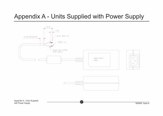
Appendix A - Units Supplied with Power Supply
Appendix A - Units Supplied with Power Supply