Embed Size (px)
Citation preview
Lenovo Flex System Interconnect Fabric
Solution Guidefor Networking OS 8.2

Note: Before using this information and the product it supports, read the general information in the Safety information and Environmental Notices and User Guide documents on the Lenovo Documentation CD and the Warranty Information document that comes with the product.
First Edition (August 2015)
© Copyright Lenovo 2015Portions © Copyright IBM Corporation 2014.
LIMITED AND RESTRICTED RIGHTS NOTICE: If data or software is delivered pursuant a General Services Administration “GSA” contract, use, reproduction, or disclosure is subject to restrictions set forth in Contract No. GS‐35F‐05925.
Lenovo and the Lenovo logo are trademarks of Lenovo in the United States, other countries, or both.
© Copyright Lenovo 2015 Contents 3
Contents
Preface . . . . . . . . . . . . . . . . . . . . . . . . . . . . . 5Who Should Use This Guide . . . . . . . . . . . . . . . . . . . . . . . 6
Typographic Conventions . . . . . . . . . . . . . . . . . . . . . . . . 7
Additional References . . . . . . . . . . . . . . . . . . . . . . . . . . 8
Chapter 1. Introduction . . . . . . . . . . . . . . . . . . . . . . 9SI Fabric Architecture . . . . . . . . . . . . . . . . . . . . . . . . . .10
Point of Delivery . . . . . . . . . . . . . . . . . . . . . . . . . .11
Hyper Distributed Fabric Protocol . . . . . . . . . . . . . . . . . . .11
SI Fabric Components . . . . . . . . . . . . . . . . . . . . . . . . . .12
SI4093 Switches . . . . . . . . . . . . . . . . . . . . . . . . . . .12
G8264CS Switches. . . . . . . . . . . . . . . . . . . . . . . . . .12
SI Fabric Features . . . . . . . . . . . . . . . . . . . . . . . . . . . .13
Layer‐2 Switching Capabilities . . . . . . . . . . . . . . . . . . . .13
Network Simplification . . . . . . . . . . . . . . . . . . . . . . .13
Management Simplification . . . . . . . . . . . . . . . . . . . . .13
Storage Integration . . . . . . . . . . . . . . . . . . . . . . . . .14
Scalable Point of Delivery . . . . . . . . . . . . . . . . . . . . . .14
Limitations . . . . . . . . . . . . . . . . . . . . . . . . . . . . . .15
Chapter 2. Initial Configuration . . . . . . . . . . . . . . . . . . 17Hardware Planning . . . . . . . . . . . . . . . . . . . . . . . . . . .18
Initial System Configuration Overview . . . . . . . . . . . . . . . . . .19
Before Configuring the SI Fabric . . . . . . . . . . . . . . . . . . .19
Using the ISCLI . . . . . . . . . . . . . . . . . . . . . . . . . . .19
Specifying SI Fabric Settings on the G8264CS . . . . . . . . . . . . . . . .20
Connecting and Attaching the SI Fabric Devices . . . . . . . . . . . . . .22
Configuring and Binding the SI4093 Switches . . . . . . . . . . . . . . .24
Reverting SI Fabric Members to Stand‐Alone Operation . . . . . . . . . . .26
Configuring the SI Fabric Management IP Addresses and Gateway . . . . . .27
Floating IP Address . . . . . . . . . . . . . . . . . . . . . . . . .29
SNMP, Telnet, and SSH Access . . . . . . . . . . . . . . . . . . . . . .30
SNMP and Switch Center Access . . . . . . . . . . . . . . . . . . .30
Telnet Access . . . . . . . . . . . . . . . . . . . . . . . . . . . .31
SSH Access . . . . . . . . . . . . . . . . . . . . . . . . . . . . .31
Displaying SI Fabric Configuration . . . . . . . . . . . . . . . . . . . .32
Chapter 3. Managing the Flex SI Fabric Solution . . . . . . . . . . . 33SI4093 License Activation Keys . . . . . . . . . . . . . . . . . . . . . .34
Obtaining Activation Keys . . . . . . . . . . . . . . . . . . . . . .34
Installing Activation Keys . . . . . . . . . . . . . . . . . . . . . .34
Transferring Activation Keys . . . . . . . . . . . . . . . . . . . . .35
Managing Systems through Master and Backup G8264CS Switches . . . . . .36
Deploying Staggered Image Upgrades for Master G8264CS Switch . . . .36
Connecting Uplink to the Data Center Network. . . . . . . . . . . . . . .37
Connecting Downlink Compute Nodes . . . . . . . . . . . . . . . . . .39
4 Flex System Interconnect Fabric: Solution Guide
Connecting to Storage Resources . . . . . . . . . . . . . . . . . . . . . 41
E‐Port Mode . . . . . . . . . . . . . . . . . . . . . . . . . . . . 41
NPV Gateway Mode . . . . . . . . . . . . . . . . . . . . . . . . 42
Enabling Full‐Fabric Function . . . . . . . . . . . . . . . . . . . . 44
Chapter 4. Flex SI Fabric -Specific ISCLI Commands . . . . . . . . . 47Information Commands . . . . . . . . . . . . . . . . . . . . . . . . . 47
Configuration Commands . . . . . . . . . . . . . . . . . . . . . . . . 48
IP Interface Configuration Commands . . . . . . . . . . . . . . . . . . 49
Software Key Commands . . . . . . . . . . . . . . . . . . . . . . . . 50
Boot Options. . . . . . . . . . . . . . . . . . . . . . . . . . . . . . 51
Appendix A. Getting Help and Technical Assistance . . . . . . . . . 53

© Copyright Lenovo 2015 Preface 5
PrefaceThe Lenovo Flex SI Fabric Solution Guide describes how to configure and use the Lenovo Networking OS 8.2 software on the Lenovo System Networking RackSwitch G8264CS (referred to as G8264CS throughout this document) and the Lenovo Flex System Fabric SI4093 System Interconnect Module (referred to as SI4093) to achieve the Flex System Interconnect Fabric (referred to as the SI Fabric).
For documentation about the physical installation of the SI4093 or G8264CS, see the respective product hardware documentation.

6 Flex System Interconnect Fabric: Solution Guide
Who Should Use This GuideThis guide is intended for network installers and system administrators engaged in configuring and maintaining a network. The administrator should be familiar with Ethernet concepts, IP addressing and SNMP configuration parameters.
© Copyright Lenovo 2015 Preface 7
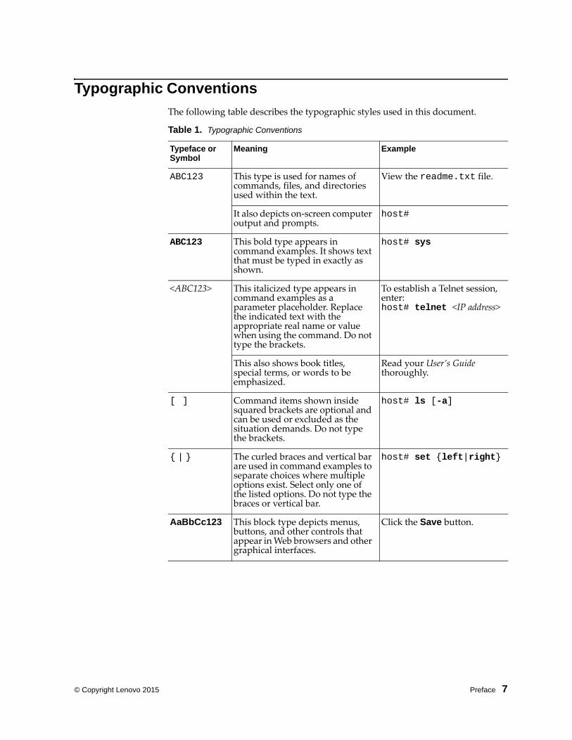
Typographic Conventions
The following table describes the typographic styles used in this document.
Table 1. Typographic Conventions
Typeface or Symbol
Meaning Example
ABC123 This type is used for names of commands, files, and directories used within the text.
View the readme.txt file.
It also depicts on‐screen computer output and prompts.
host#
ABC123 This bold type appears in command examples. It shows text that must be typed in exactly as shown.
host# sys
<ABC123> This italicized type appears in command examples as a parameter placeholder. Replace the indicated text with the appropriate real name or value when using the command. Do not type the brackets.
To establish a Telnet session, enter:host# telnet <IP address>
This also shows book titles, special terms, or words to be emphasized.
Read your User’s Guide thoroughly.
[ ] Command items shown inside squared brackets are optional and can be used or excluded as the situation demands. Do not type the brackets.
host# ls [a]
{ | } The curled braces and vertical bar are used in command examples to separate choices where multiple options exist. Select only one of the listed options. Do not type the braces or vertical bar.
host# set {left|right}
AaBbCc123 This block type depicts menus, buttons, and other controls that appear in Web browsers and other graphical interfaces.
Click the Save button.
8 Flex System Interconnect Fabric: Solution Guide
Additional ReferencesAdditional information about installing and configuring the SI Fabric is available in the following guides:
Lenovo RackSwitch G8264CS Application Guide for Networking OS 8.2
Lenovo RackSwitch G8264CS ISCLI Command Reference for Networking OS 8.2
Lenovo Flex System Fabric SI4093 System Interconnect Module Application Guide for Networking OS 8.2
Lenovo Flex System Fabric SI4093 System Interconnect Module ISCLI Command Reference for Networking OS 8.2

© Copyright Lenovo 2015 Chapter 1: Introduction 9
Chapter 1. Introduction
This Solution Guide introduces the Lenovo Flex System Interconnect Fabric (referred to as the SI Fabric throughout this document). The SI Fabric provides a single point of network access for data center Ethernet and Fibre Channel network. It supports Flex System compute nodes and internal and external storage nodes for computing and storage resources capabilities in a Flex System chassis.

10 Flex System Interconnect Fabric: Solution Guide
SI Fabric Architecture
The SI Fabric is managed through a single entity, the user‐designated Master switch, and passed on to the internal components. The SI Fabric integrates the following components:
Two G8264CS switches
Up to 9 Flex System chassis, each with two SI4093 modules in paired bays (Bay 1 and Bay 2, or alternately Bay 3 and Bay 4), for a total of up to 18 SI4093 modules.
Note: If the servers have an extra net card, the chassis supports up to 4 switches.
Up to 126 half‐width Flex System compute nodes (up to 14 per chassis) with 10Gb Converged Network Adapters (CNAs)
One or more internal Flex System V7000 storage node and external Storwize V7000 storage system, as a highly integrated Point Of Delivery (POD) solution for data centers
Figure 1. Flex System Interconnect Fabric Components
Figure 2 on page 11 illustrates the SI Fabric connections to storage and computing resources.

© Copyright Lenovo 2015 Chapter 1: Introduction 11
Figure 2. Flex System Interconnect Fabric Environment
Point of Delivery
A Point Of Delivery (POD) is a module of network, compute, storage, and application components that work together to deliver networking services. In service provider infrastructure, the POD supports cloud computing services to sustain scalability as usage grows.
The SI Fabric integrates the entire POD solution into a seamless network fabric for server and storage under single IP management and attaches to upstream data center network as a loop‐free layer‐2 stub network fabric with single Ethernet uplink connection or trunk group to each layer‐2 network.
The SI Fabric POD solution requires network provisioning only for uplink connections to a data center network, downlink connections to server nodes, and connections to storage nodes.
Hyper Distributed Fabric Protocol
The SI Fabric utilizes the Lenovo proprietary hyper distributed fabric protocol (hDFP) to provide a loop‐free network fabric system for data and storage traffic. It integrates compute, network, and storage components as a single IP management switch system. All G8264CS switches and SI4093 switches are configured to run in SI Fabric mode.
The hDFP aggregates all network switching modules into a single logical switch, the SI Fabric, with G8264CS switches as master and backup nodes at the aggregation layer and SI4093 switches as member nodes at the access layer.
Configuration and management of the networking component is done via the management IP interface at master node of the logical switch. If the master node fails, the backup G8264CS switch will take over as the new master node of the logical switch and the old master node will turn into new backup node once recovered.
12 Flex System Interconnect Fabric: Solution Guide
SI Fabric Components
The SI Fabric unifies SI4093, G8264CS, and storage hardware components.
SI4093 Switches
The Lenovo Flex System Fabric SI4093 System Interconnect Module (SI4093) provides a transparent network interface between server elements within the chassis and the upstream data and storage networking infrastructure. The standard SI4093 provides 14 internal 10GbE ports as downlinks for server connectivity and 10 external 10GbE Ethernet fabric ports for connection with G8264CS switches.
The SI Fabric can also support expansion of additional 28 internal and 12 externals 10Gbps ports, with optional Feature on Demand (FoD) license keys. Within the SI Fabric, SI4093 provides convergence of traditional Ethernet traffic with Fibre Channel over Ethernet (FCoE) storage session traffic and facilitates low‐latency, media‐speed server‐to‐server traffic within the chassis, or server‐to‐uplink traffic based on the hDFP protocol.
G8264CS Switches
The Lenovo System Networking RackSwitch G8264CS converged switch contains 36 10GbE small form‐factor pluggable plus (SFP+) ports and four 40GbE quad small‐form‐factor pluggable plus (QSFP+) ports, and twelve Omni Ports. Omni Port technology allows the same port to be used as a 10G Ethernet port or 4/8G Fibre Channel port.
© Copyright Lenovo 2015 Chapter 1: Introduction 13
SI Fabric Features
Layer-2 Switching Capabilities
The SI Fabric provides the following layer‐2 switching capabilities:
Converged Enhanced Ethernet (CEE)
10GbE Ethernet switching
Fibre Channel over Ethernet (FCoE) and FC/FCoE capabilities
N Port Virtualization (NPV) Gateway
Full Fabric FC/FCoE switch
Network Simplification
The SI Fabric provides the following network simplification features:
Seamless network fabric for server and storage to connect with data center
Offers a loop‐free network fabric without Spanning Tree Protocol (STP) complexity.
Minimizes network latency by local L2 switching at every interconnect component, and minimizes the loss of data during network failover within the fabric.
Converges Ethernet for lossless storage traffic.
Adds new components to an already running fabric with no traffic loss or disturbance in the existing traffic flow.
Integrates Fibre Channel Forwarder (FCF) to provide end‐to‐end Fibre Channel over Ethernet (FCoE) storage functionality within the POD without the need of expensive Fibre Channel switch.
Supports single‐fabric mode topology, dual‐fabric mode topology, and full‐fabric topology.
Offers different levels of redundancy inside the fabric: static/LACP distributed portchannels, teaming, dual interconnection redundancy.
Management Simplification
The SI Fabric provides the following management simplification features:
High availability with master and backup nodes
Staggered upgrade enables upgrading the fabric with no service or connection downtime.
Minimizes managed network elements with single point of management at the master node of the entire fabric.
Establishes clear administrative boundaries in data center by pushing traditional networking configuration outside of the POD.
Integrates physical and virtual infrastructure management for compute, network, and storage elements.
14 Flex System Interconnect Fabric: Solution Guide
Storage Integration
The SI Fabric simplifies integration of storage and storage virtualization with Lenovo Flex System V7000 storage node and access to external SAN storage infrastructure, such as Lenovo Storwize V7000.
Scalable Point of Delivery
The SI Fabric provides the following scalability features:
The SI Fabric enables the size of the POD to grow without the additions of management complexity.
The SI Fabric adds additional chassis resources up to the maximum configuration under single IP management of the POD.
Expert Integrated Systems
The SI Fabric simplifies the I/O connectivity in Foundation offerings and improves the time to value of an integrated system.
The SI Fabric can be leveraged in Pure Application and Pure Data configurations improving the ability to roll in racks of tested solutions into existing data centers.
© Copyright Lenovo 2015 Chapter 1: Introduction 15
Limitations
Following is a list of Flex System Interconnect Fabric limitations for the current release:
The SI Fabric requires Lenovo Networking OS version 7.7.5 or greater for all stand‐alone switches.
Lenovo does not support mixing 10Gb and 40Gb SI Fabric port speeds in SI Fabric logical switches. Lenovo recommends that you reserve additional SI Fabric ports on both G8264CS switches for future expansion.
All external ports on SI4093 devices are automatically configured as Fabric Ports, requiring no additional configuration. Omni Ports on the RackSwitch G8264CS cannot be configured as Fabric Ports.
To change a port from Ethernet to Fabric mode on the aggregation switches (TORs), the switch needs to be rebooted. If a new chassis is added to the solution and fabric ports need to be reconfigured on both TORs, the user can still operate master/backup failover and reboot the master and backup one by one in order to keep the full access to its servers/storage during the process.

16 Flex System Interconnect Fabric: Solution Guide

© Copyright Lenovo 2015 Chapter 2: Initial Configuration 17
Chapter 2. Initial Configuration
This chapter explains how to set up the software components of the Flex System Interconnect Fabric (SI Fabric).

18 Flex System Interconnect Fabric: Solution Guide
Hardware Planning
The minimum configuration requires two G8264CS switches, two Flex System chassis populated with two SI4093 switches at each chassis, two half‐width Flex System compute nodes with 10Gb CNAs at each chassis, and Storwize V7000 storage system.
The SI Fabric supports two G8264CS switches, up to nine Flex System chassis populated with two SI4093 switches at each chassis, up to 126 half‐width Flex System compute nodes and external Storwize V7000 storage system.
The SI Fabric acts as a simple pass‐thru switch that provides a transparent network interface between server elements within the chassis and the upstream data and storage networking infrastructure.
The base SI4093 switch provides 14 internal 10GbE ports as downlinks for server connectivity and ten external 10GbE Ethernet fabric ports for connection with G8264CS switches in the SI Fabric.
An additional 28 internal and 12 externals 10Gbps ports are available for expansion with optional Feature on Demand license keys.
The SI4093 switch in the SI Fabric provides the convergence of traditional Ethernet traffic with Fibre Channel over Ethernet (FCoE) storage.
© Copyright Lenovo 2015 Chapter 2: Initial Configuration 19
Initial System Configuration Overview
To deploy the Flex System Interconnect Fabric from a stand‐alone topology:
1. Specify SI Fabric ports and SI Fabric‐related settings at G8264CS switches and
reboot again to take effect (see “Specifying SI Fabric Settings on the G8264CS” on
page 20).
2. Connect minimum two 10Gb Ethernet cables as SI Fabric links between the two
G8264CS switches. Also connect two 10Gb Ethernet cables from each SI4093 switch
to each G8264CS switch. See “Connecting and Attaching the SI Fabric Devices” on
page 22.
Note: Using more links to connect switches will increase the traffic bandwidth inside the fabric.
3. Once the master G8264CS detects all attached SI4093 switches, bind them to the SI
Fabric (see “Configuring and Binding the SI4093 Switches” on page 24).
4. Configure the management IP address and gateway information at the master and
backup G8264CS switches for future data and storage VLAN and port
configurations (see “Configuring the SI Fabric Management IP Addresses and
Gateway” on page 27).
5. Enable additional management access (see “SNMP, Telnet, and SSH Access” on
page 30).
6. If required, install FoD license keys on SI4093 switches (see “SI4093 License
Activation Keys” on page 34).
Before Configuring the SI Fabric
Before you begin configuring the SI Fabric, you must have this information:
IP addresses for your routers, servers. and attached network devices
VLAN information (names and numbers)
Physical layout, storage, and data connections for the SI Fabric
Using the ISCLI
Use the ISCLI via switch serial console to configure the SI Fabric. After the SI Fabric is initialized, you can use ISCLI over Telnet, or SNMP for additional configuration and management tasks.
The ISCLI provides a direct method for collecting switch information and performing switch upgrade and configuration. Using a basic terminal, the ISCLI allows you to view information and statistics about the switch, and to perform any necessary configuration.
20 Flex System Interconnect Fabric: Solution Guide
Specifying SI Fabric Settings on the G8264CS
After you have rebooted all G8264CS and SI4093 switches with installed SI Fabric software images, they will load factory‐default switch settings and default SI Fabric settings.
Perform the following configuration procedure on each G8264CS switch.
Note: Lenovo recommends that you perform side‐by‐side logical switch setting review and re‐configuration at both G8264CS switches.
1. Connect to the G8264CS switch serial console.
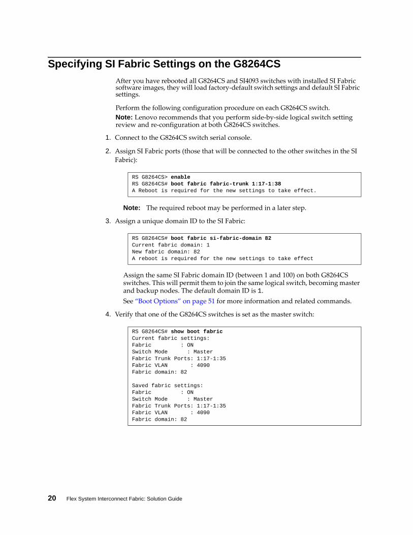
2. Assign SI Fabric ports (those that will be connected to the other switches in the SI
Fabric):
Note: The required reboot may be performed in a later step.
3. Assign a unique domain ID to the SI Fabric:
Assign the same SI Fabric domain ID (between 1 and 100) on both G8264CS switches. This will permit them to join the same logical switch, becoming master and backup nodes. The default domain ID is 1.
See “Boot Options” on page 51 for more information and related commands.
4. Verify that one of the G8264CS switches is set as the master switch:
RS G8264CS> enableRS G8264CS# boot fabric fabrictrunk 1:171:38A Reboot is required for the new settings to take effect.
RS G8264CS# boot fabric sifabricdomain 82Current fabric domain: 1New fabric domain: 82A reboot is required for the new settings to take effect
RS G8264CS# show boot fabric Current fabric settings: Fabric : ONSwitch Mode : MasterFabric Trunk Ports: 1:171:35Fabric VLAN : 4090Fabric domain: 82
Saved fabric settings: Fabric : ONSwitch Mode : MasterFabric Trunk Ports: 1:171:35Fabric VLAN : 4090Fabric domain: 82
© Copyright Lenovo 2015 Chapter 2: Initial Configuration 21
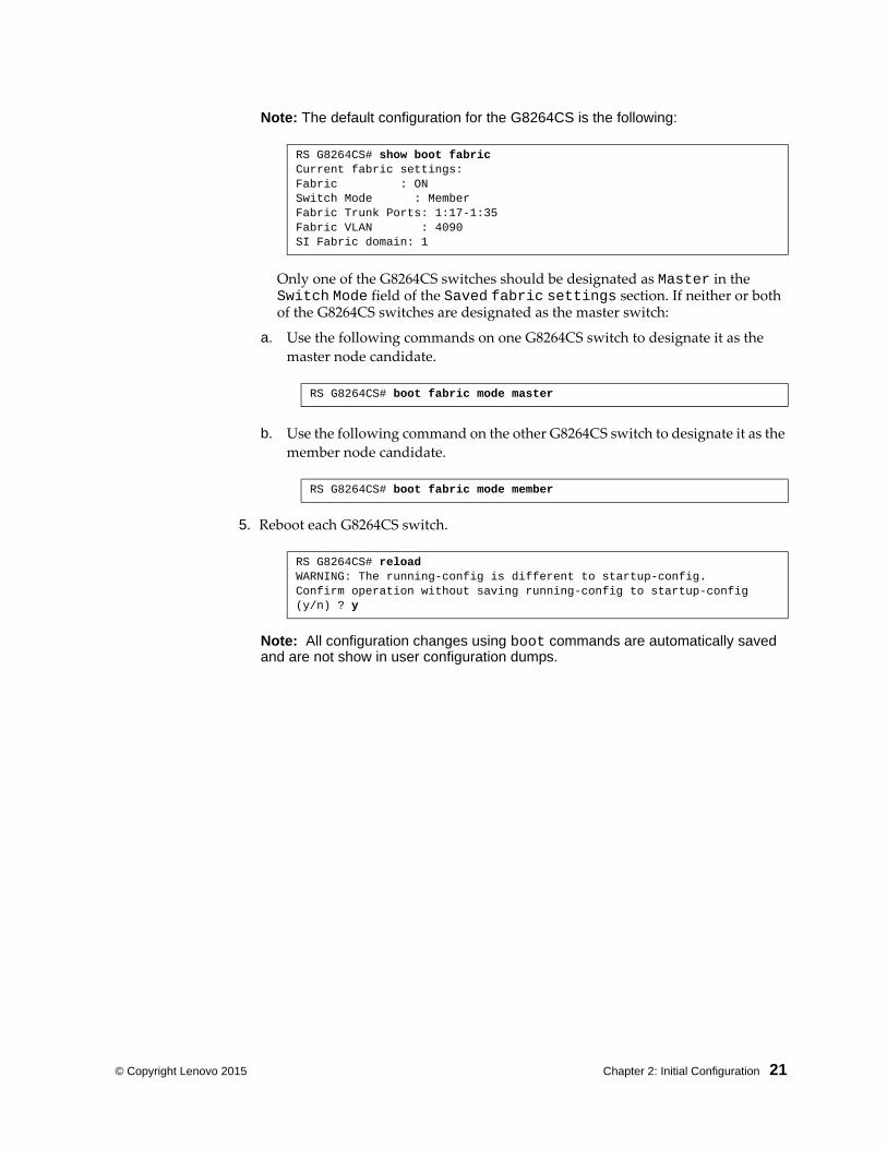
Note: The default configuration for the G8264CS is the following:
Only one of the G8264CS switches should be designated as Master in the Switch Mode field of the Saved fabric settings section. If neither or both of the G8264CS switches are designated as the master switch:
a. Use the following commands on one G8264CS switch to designate it as the
master node candidate.
b. Use the following command on the other G8264CS switch to designate it as the
member node candidate.
5. Reboot each G8264CS switch.
Note: All configuration changes using boot commands are automatically saved and are not show in user configuration dumps.
RS G8264CS# show boot fabric Current fabric settings: Fabric : ONSwitch Mode : MemberFabric Trunk Ports: 1:171:35Fabric VLAN : 4090SI Fabric domain: 1
RS G8264CS# boot fabric mode master
RS G8264CS# boot fabric mode member
RS G8264CS# reloadWARNING: The runningconfig is different to startupconfig.Confirm operation without saving runningconfig to startupconfig (y/n) ? y
22 Flex System Interconnect Fabric: Solution Guide
Connecting and Attaching the SI Fabric Devices
Once both G8264CS switches have completely rebooted, the SI Fabric components (G8264CS and SI4093 switches) can be connected together.
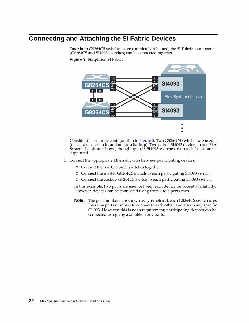
Figure 3. Simplified SI Fabric
Consider the example configuration in Figure 3. Two G8264CS switches are used (one as a master node, and one as a backup). Two paired SI4093 devices in one Flex System chassis are shown, though up to 18 SI4093 switches in up to 9 chassis are supported.
1. Connect the appropriate Ethernet cables between participating devices:
Connect the two G8264CS switches together.
Connect the master G8264CS switch to each participating SI4093 switch.
Connect the backup G8264CS switch to each participating SI4093 switch.
In this example, two ports are used between each device for robust availability. However, devices can be connected using from 1 to 8 ports each.
Note: The port numbers are shown as symmetrical: each G8264CS switch uses the same ports numbers to connect to each other, and also to any specific SI4093. However, this is not a requirement; participating devices can be connected using any available fabric ports.
G8264CS SI4093
SI4093G8264CS ...EXT2EXT3EXT4
EXT1202122
19
17 18
17 18
202122
19EXT2EXT3EXT4
EXT1
Flex System chassis
© Copyright Lenovo 2015 Chapter 2: Initial Configuration 23
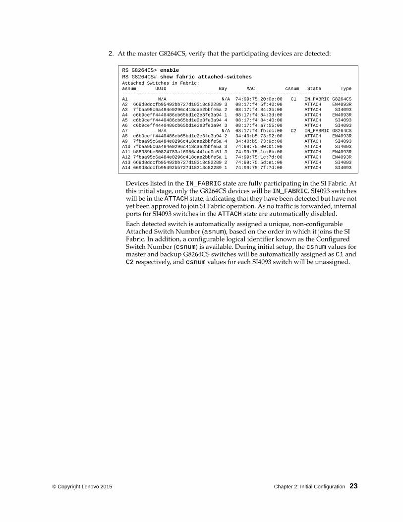
2. At the master G8264CS, verify that the participating devices are detected:
Devices listed in the IN_FABRIC state are fully participating in the SI Fabric. At this initial stage, only the G8264CS devices will be IN_FABRIC. SI4093 switches will be in the ATTACH state, indicating that they have been detected but have not yet been approved to join SI Fabric operation. As no traffic is forwarded, internal ports for SI4093 switches in the ATTACH state are automatically disabled.
Each detected switch is automatically assigned a unique, non‐configurable Attached Switch Number (asnum), based on the order in which it joins the SI Fabric. In addition, a configurable logical identifier known as the Configured Switch Number (csnum) is available. During initial setup, the csnum values for master and backup G8264CS switches will be automatically assigned as C1 and C2 respectively, and csnum values for each SI4093 switch will be unassigned.
RS G8264CS> enableRS G8264CS# show fabric attachedswitchesAttached Switches in Fabric: asnum UUID Bay MAC csnum State TypeA1 N/A N/A 74:99:75:20:0e:00 C1 IN_FABRIC G8264CSA2 669d8dccfb95492bb727d18313c82289 3 08:17:f4:5f:40:00 ATTACH EN4093RA3 7fbaa95c6a484e0296c418cae2bbfe5a 2 08:17:f4:84:3b:00 ATTACH SI4093A4 c6b9ceff4440486cb65bd1e2e3fe3a94 1 08:17:f4:84:3d:00 ATTACH EN4093RA5 c6b9ceff4440486cb65bd1e2e3fe3a94 4 08:17:f4:84:40:00 ATTACH SI4093A6 c6b9ceff4440486cb65bd1e2e3fe3a94 3 08:17:f4:a7:55:00 ATTACH SI4093A7 N/A N/A 08:17:f4:fb:cc:00 C2 IN_FABRIC G8264CSA8 c6b9ceff4440486cb65bd1e2e3fe3a94 2 34:40:b5:73:92:00 ATTACH EN4093RA9 7fbaa95c6a484e0296c418cae2bbfe5a 4 34:40:b5:73:9c:00 ATTACH SI4093A10 7fbaa95c6a484e0296c418cae2bbfe5a 3 74:99:75:00:D1:00 ATTACH SI4093A11 b88989be60824783af6956a441cd0c61 3 74:99:75:1c:6b:00 ATTACH EN4093RA12 7fbaa95c6a484e0296c418cae2bbfe5a 1 74:99:75:1c:7d:00 ATTACH EN4093RA13 669d8dccfb95492bb727d18313c82289 2 74:99:75:5d:e1:00 ATTACH SI4093A14 669d8dccfb95492bb727d18313c82289 1 74:99:75:7f:7d:00 ATTACH SI4093
24 Flex System Interconnect Fabric: Solution Guide
Configuring and Binding the SI4093 Switches
Newly detected SI4093 switches are initially isolated from SI Fabric operation. Until they are explicitly permitted to operate within the SI Fabric, they will appear in the ATTACH state and their internal ports will remain automatically disabled.
To approve the SI4093 switches for SI Fabric operation, each member SI4093 switch listed in the ATTACH state must be configured with a csnum. Once the csnum is assigned, the SI4093 switch will transition to the IN_FABRIC state.
All SI4093 configuration is performed at the master G8264CS switch. On the master G8264CS switch, the SI4093 csnum values may be configured automatically for all switches at once, or manually for each individual switch.
Note: Fabric bind command is non-disruptive. When a new switch is added to the fabric, the command binds it to the next available switch number (csum).
To automatically assign csnum values for all attached SI4093 switches, use the following commands:
To manual assign a desired csnum value for any specific SI4093 switch, use the following configuration mode command:
Repeat the manual command for each participating SI4093 switch.
Note: The master G8264CS always has a csnum of C1, and the backup G8264CS always has a csnum of C2. These cannot be manually changed.
When a new csnum is assigned, the member switch will leave and rejoin the SI Fabric and update its port list accordingly. The following sequence occurs:
If the desired csnum currently belongs to another member switch, that member switch will placed in the ATTACH state and wait for a new csnum to be assigned before it may rejoin the SI Fabric.
The csnum and binding assignment will be saved in the SI Fabric configuration as individual csnum entries with the physical switch MAC address or csnum and Flex System UUID plus IO bay number.
In future reboots, each SI Fabric switch will retain the csnum saved in its binding configuration.The asnum values, however, may change, depending on the specific sequence in which switches are returned to service.
RS G8264CS# configure terminalRS G8264CS(config)# fabric bind
RS G8264CS(config)# fabric switchnumber <csnum> bind <asnum>
© Copyright Lenovo 2015 Chapter 2: Initial Configuration 25
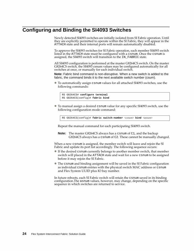
You can use the show fabric attached‐switches command to verify that the participating devices are properly configured. For example:
The example output shows all detected switches configured with csnum values operating in the IN_FABRIC state. This indicates that the binding process is complete and all devices in the SI Fabric are acting as a single logical switch.
RS G8264CS(config)# show fabric attachedswitchesAttached Switches in Fabric: asnum UUID Bay MAC csnum State TypeA1 N/A N/A 74:99:75:20:0e:00 C1 IN_FABRIC G8264CSA2 669d8dccfb95492bb727d18313c82289 3 08:17:f4:5f:40:00 C9 IN_FABRIC EN4093RA3 7fbaa95c6a484e0296c418cae2bbfe5a 2 08:17:f4:84:3b:00 C12 IN_FABRIC SI4093A4 c6b9ceff4440486cb65bd1e2e3fe3a94 1 08:17:f4:84:3d:00 C3 IN_FABRIC EN4093RA5 c6b9ceff4440486cb65bd1e2e3fe3a94 4 08:17:f4:84:40:00 C6 IN_FABRIC SI4093A6 c6b9ceff4440486cb65bd1e2e3fe3a94 3 08:17:f4:a7:55:00 C5 IN_FABRIC SI4093A7 N/A N/A 08:17:f4:fb:cc:00 C2 IN_FABRIC G8264CSA8 c6b9ceff4440486cb65bd1e2e3fe3a94 2 34:40:b5:73:92:00 C4 IN_FABRIC EN4093RA9 7fbaa95c6a484e0296c418cae2bbfe5a 4 34:40:b5:73:9c:00 C14 IN_FABRIC SI4093A10 7fbaa95c6a484e0296c418cae2bbfe5a 3 74:99:75:00:D1:00 C13 IN_FABRIC SI4093A11 b88989be60824783af6956a441cd0c61 3 74:99:75:1c:6b:00 C15 IN_FABRIC EN4093RA12 7fbaa95c6a484e0296c418cae2bbfe5a 1 74:99:75:1c:7d:00 C11 IN_FABRIC EN4093RA13 669d8dccfb95492bb727d18313c82289 2 74:99:75:5d:e1:00 C8 IN_FABRIC SI4093A14 669d8dccfb95492bb727d18313c82289 1 74:99:75:7f:7d:00 C7 IN_FABRIC SI4093
26 Flex System Interconnect Fabric: Solution Guide
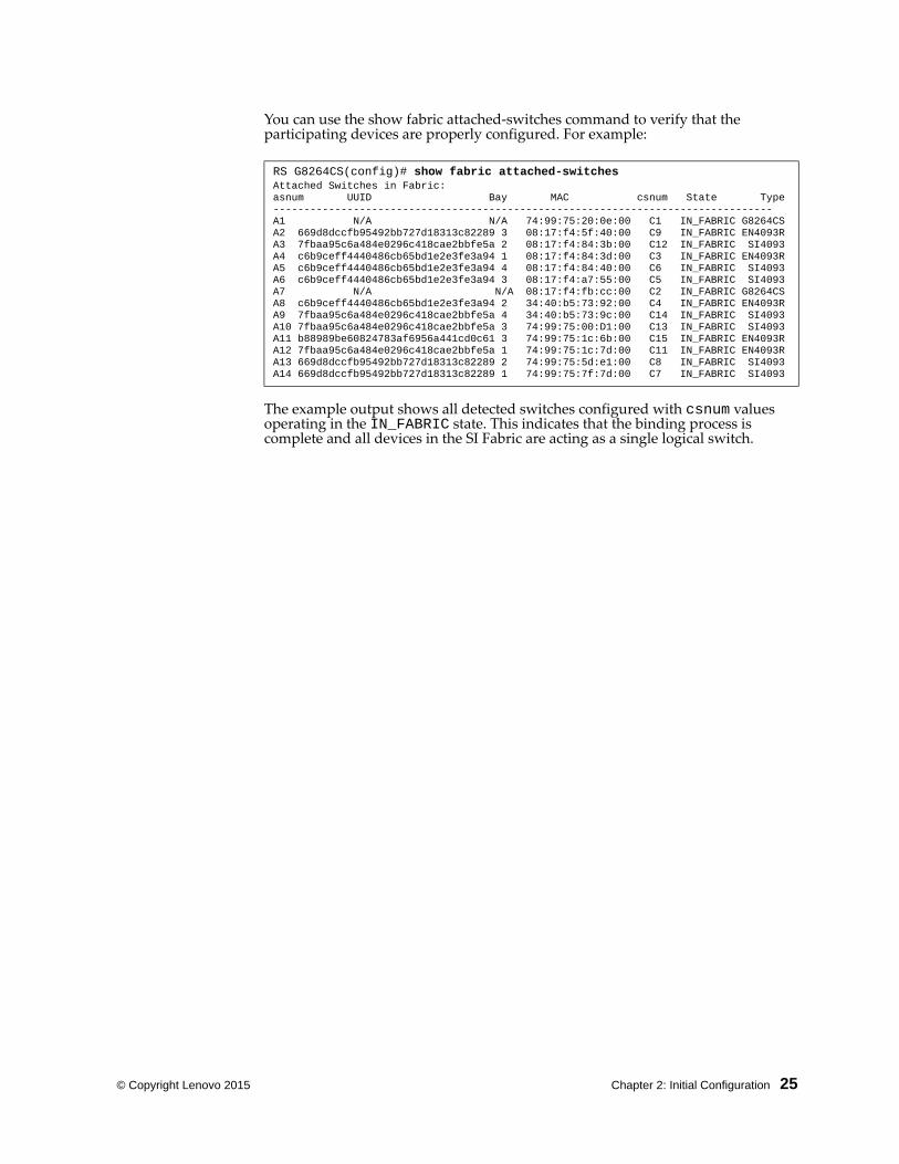
Reverting SI Fabric Members to Stand-Alone Operation
You can remove any member switch from the SI Fabric and revert it to act as a stand‐alone switch.
At the master G8263CS switch, use the following commands to revert any member switch and re‐install a stand‐alone software image:
RS G8264CS> enableRS G8264CS# copy tftp {image1|image2} address <IP address> filename <stand‐alone image filename> {dataport|mgtport} switchnumber <asnum>
© Copyright Lenovo 2015 Chapter 2: Initial Configuration 27
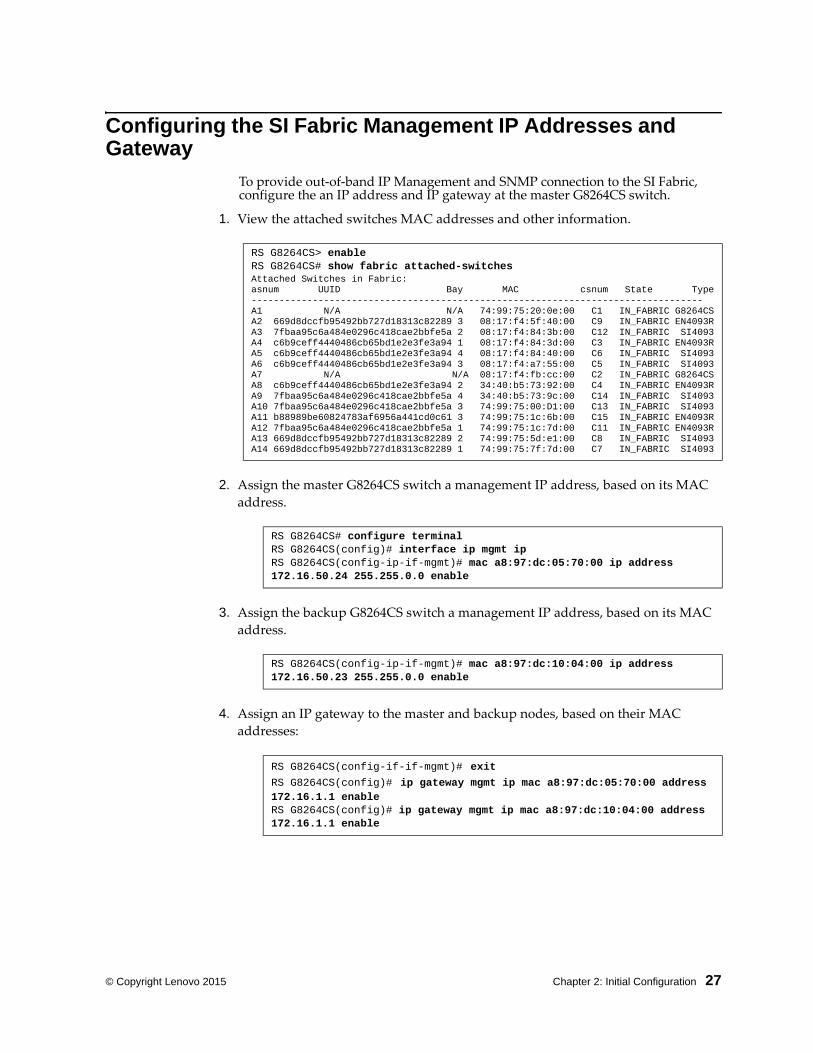
Configuring the SI Fabric Management IP Addresses and Gateway
To provide out‐of‐band IP Management and SNMP connection to the SI Fabric, configure the an IP address and IP gateway at the master G8264CS switch.
1. View the attached switches MAC addresses and other information.
2. Assign the master G8264CS switch a management IP address, based on its MAC
address.
3. Assign the backup G8264CS switch a management IP address, based on its MAC
address.
4. Assign an IP gateway to the master and backup nodes, based on their MAC
addresses:
RS G8264CS> enableRS G8264CS# show fabric attachedswitchesAttached Switches in Fabric: asnum UUID Bay MAC csnum State TypeA1 N/A N/A 74:99:75:20:0e:00 C1 IN_FABRIC G8264CSA2 669d8dccfb95492bb727d18313c82289 3 08:17:f4:5f:40:00 C9 IN_FABRIC EN4093RA3 7fbaa95c6a484e0296c418cae2bbfe5a 2 08:17:f4:84:3b:00 C12 IN_FABRIC SI4093A4 c6b9ceff4440486cb65bd1e2e3fe3a94 1 08:17:f4:84:3d:00 C3 IN_FABRIC EN4093RA5 c6b9ceff4440486cb65bd1e2e3fe3a94 4 08:17:f4:84:40:00 C6 IN_FABRIC SI4093A6 c6b9ceff4440486cb65bd1e2e3fe3a94 3 08:17:f4:a7:55:00 C5 IN_FABRIC SI4093A7 N/A N/A 08:17:f4:fb:cc:00 C2 IN_FABRIC G8264CSA8 c6b9ceff4440486cb65bd1e2e3fe3a94 2 34:40:b5:73:92:00 C4 IN_FABRIC EN4093RA9 7fbaa95c6a484e0296c418cae2bbfe5a 4 34:40:b5:73:9c:00 C14 IN_FABRIC SI4093A10 7fbaa95c6a484e0296c418cae2bbfe5a 3 74:99:75:00:D1:00 C13 IN_FABRIC SI4093A11 b88989be60824783af6956a441cd0c61 3 74:99:75:1c:6b:00 C15 IN_FABRIC EN4093RA12 7fbaa95c6a484e0296c418cae2bbfe5a 1 74:99:75:1c:7d:00 C11 IN_FABRIC EN4093RA13 669d8dccfb95492bb727d18313c82289 2 74:99:75:5d:e1:00 C8 IN_FABRIC SI4093A14 669d8dccfb95492bb727d18313c82289 1 74:99:75:7f:7d:00 C7 IN_FABRIC SI4093
RS G8264CS# configure terminalRS G8264CS(config)# interface ip mgmt ipRS G8264CS(configipifmgmt)# mac a8:97:dc:05:70:00 ip address 172.16.50.24 255.255.0.0 enable
RS G8264CS(configipifmgmt)# mac a8:97:dc:10:04:00 ip address 172.16.50.23 255.255.0.0 enable
RS G8264CS(configififmgmt)# exitRS G8264CS(config)# ip gateway mgmt ip mac a8:97:dc:05:70:00 address 172.16.1.1 enableRS G8264CS(config)# ip gateway mgmt ip mac a8:97:dc:10:04:00 address 172.16.1.1 enable
28 Flex System Interconnect Fabric: Solution Guide
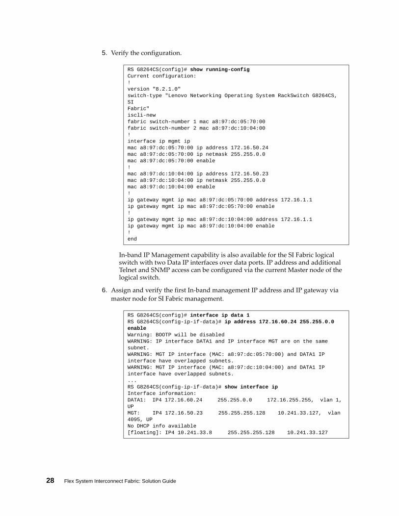
5. Verify the configuration.
In‐band IP Management capability is also available for the SI Fabric logical switch with two Data IP interfaces over data ports. IP address and additional Telnet and SNMP access can be configured via the current Master node of the logical switch.
6. Assign and verify the first In‐band management IP address and IP gateway via
master node for SI Fabric management.
RS G8264CS(config)# show runningconfig Current configuration:!version "8.2.1.0"switchtype "Lenovo Networking Operating System RackSwitch G8264CS, SIFabric"isclinewfabric switchnumber 1 mac a8:97:dc:05:70:00fabric switchnumber 2 mac a8:97:dc:10:04:00!interface ip mgmt ipmac a8:97:dc:05:70:00 ip address 172.16.50.24mac a8:97:dc:05:70:00 ip netmask 255.255.0.0mac a8:97:dc:05:70:00 enable!mac a8:97:dc:10:04:00 ip address 172.16.50.23mac a8:97:dc:10:04:00 ip netmask 255.255.0.0mac a8:97:dc:10:04:00 enable!ip gateway mgmt ip mac a8:97:dc:05:70:00 address 172.16.1.1ip gateway mgmt ip mac a8:97:dc:05:70:00 enable!ip gateway mgmt ip mac a8:97:dc:10:04:00 address 172.16.1.1ip gateway mgmt ip mac a8:97:dc:10:04:00 enable!end
RS G8264CS(config)# interface ip data 1RS G8264CS(configipifdata)# ip address 172.16.60.24 255.255.0.0 enable Warning: BOOTP will be disabledWARNING: IP interface DATA1 and IP interface MGT are on the same subnet.WARNING: MGT IP interface (MAC: a8:97:dc:05:70:00) and DATA1 IP interface have overlapped subnets.WARNING: MGT IP interface (MAC: a8:97:dc:10:04:00) and DATA1 IP interface have overlapped subnets....RS G8264CS(configipifdata)# show interface ipInterface information:DATA1: IP4 172.16.60.24 255.255.0.0 172.16.255.255, vlan 1, UP MGT: IP4 172.16.50.23 255.255.255.128 10.241.33.127, vlan 4095, UPNo DHCP info available[floating]: IP4 10.241.33.8 255.255.255.128 10.241.33.127
© Copyright Lenovo 2015 Chapter 2: Initial Configuration 29
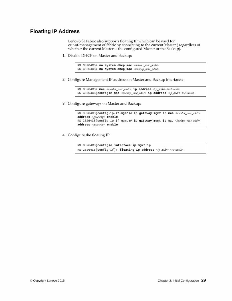
Floating IP Address
Lenovo SI Fabric also supports floating IP which can be used for out‐of‐management of fabric by connecting to the current Master ( regardless of whether the current Master is the configured Master or the Backup).
1. Disable DHCP on Master and Backup:
2. Configure Management IP address on Master and Backup interfaces:
3. Configure gateways on Master and Backup:
4. Configure the floating IP:
RS G8264CS# no system dhcp mac <master_mac_addr>RS G8264CS# no system dhcp mac <backup_mac_addr>
RS G8264CS# mac <master_mac_addr> ip address <ip_addr> <netmask>RS G8264CS(config)# mac <backup_mac_addr> ip address <ip_addr> <netmask>
RS G8264CS(configipifmgmt)# ip gateway mgmt ip mac <master_mac_addr> address <gateway> enableRS G8264CS(configipifmgmt)# ip gateway mgmt ip mac <backup_mac_addr> address <gateway> enable
RS G8264CS(config)# interface ip mgmt ipRS G8264CS(configif)# floating ip address <ip_addr> <netmask>
30 Flex System Interconnect Fabric: Solution Guide
SNMP, Telnet, and SSH Access
Many SI Fabric features may be managed remotely using SNMP (and Switch Center), Telnet, or SSH.
Remote management requires prior configuration of the SI Fabric Management IP address and gateway (see “Configuring the SI Fabric Management IP Addresses and Gateway” on page 27).
SNMP and Switch Center Access
The SI Fabric can be managed via Simple Network Management Protocol (SNMP) using an SNMP management tool such as Switch Center. SNMP resource management and switch access are similar to operating a stand‐alone G8264CS switch.
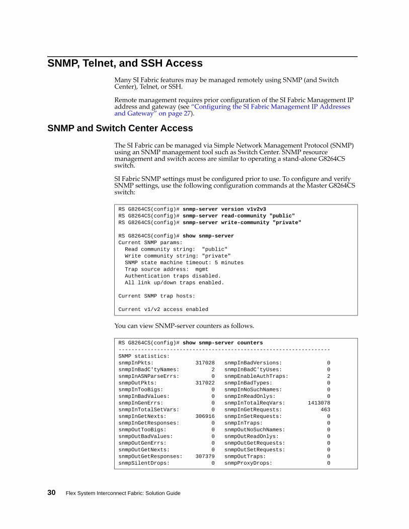
SI Fabric SNMP settings must be configured prior to use. To configure and verify SNMP settings, use the following configuration commands at the Master G8264CS switch:
You can view SNMP‐server counters as follows.
RS G8264CS(config)# snmpserver version v1v2v3 RS G8264CS(config)# snmpserver readcommunity "public"RS G8264CS(config)# snmpserver writecommunity "private"
RS G8264CS(config)# show snmpserverCurrent SNMP params: Read community string: "public" Write community string: "private" SNMP state machine timeout: 5 minutes Trap source address: mgmt Authentication traps disabled. All link up/down traps enabled.
Current SNMP trap hosts:
Current v1/v2 access enabled
RS G8264CS(config)# show snmpserver counters SNMP statistics:snmpInPkts: 317028 snmpInBadVersions: 0snmpInBadC'tyNames: 2 snmpInBadC'tyUses: 0snmpInASNParseErrs: 0 snmpEnableAuthTraps: 2snmpOutPkts: 317022 snmpInBadTypes: 0snmpInTooBigs: 0 snmpInNoSuchNames: 0snmpInBadValues: 0 snmpInReadOnlys: 0snmpInGenErrs: 0 snmpInTotalReqVars: 1413078snmpInTotalSetVars: 0 snmpInGetRequests: 463snmpInGetNexts: 306916 snmpInSetRequests: 0snmpInGetResponses: 0 snmpInTraps: 0snmpOutTooBigs: 0 snmpOutNoSuchNames: 0snmpOutBadValues: 0 snmpOutReadOnlys: 0snmpOutGenErrs: 0 snmpOutGetRequests: 0snmpOutGetNexts: 0 snmpOutSetRequests: 0snmpOutGetResponses: 307379 snmpOutTraps: 0snmpSilentDrops: 0 snmpProxyDrops: 0
© Copyright Lenovo 2015 Chapter 2: Initial Configuration 31
Telnet Access
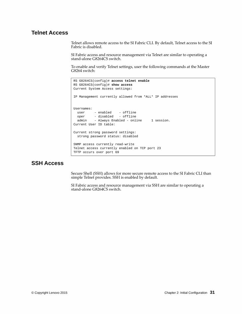
Telnet allows remote access to the SI Fabric CLI. By default, Telnet access to the SI Fabric is disabled.
SI Fabric access and resource management via Telnet are similar to operating a stand‐alone G8264CS switch.
To enable and verify Telnet settings, user the following commands at the Master G8264 switch:
SSH Access
Secure Shell (SSH) allows for more secure remote access to the SI Fabric CLI than simple Telnet provides. SSH is enabled by default.
SI Fabric access and resource management via SSH are similar to operating a stand‐alone G8264CS switch.
RS G8264CS(config)# access telnet enableRS G8264CS(config)# show accessCurrent System Access settings:
IP Management currently allowed from *ALL* IP addresses
Usernames: user enabled offline oper disabled offline admin Always Enabled online 1 session.Current User ID table:
Current strong password settings: strong password status: disabled
SNMP access currently readwriteTelnet access currently enabled on TCP port 23TFTP occurs over port 69
32 Flex System Interconnect Fabric: Solution Guide
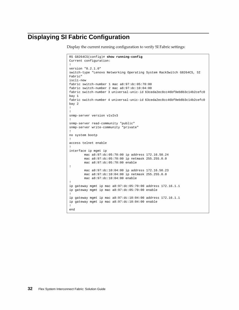
Displaying SI Fabric Configuration
Display the current running configuration to verify SI Fabric settings:
RS G8264CS(config)# show runningconfig Current configuration:!version "8.2.1.0"switchtype "Lenovo Networking Operating System RackSwitch G8264CS, SI Fabric"isclinewfabric switchnumber 1 mac a8:97:dc:05:70:00fabric switchnumber 2 mac a8:97:dc:10:04:00fabric switchnumber 3 universalunicid 63ceda2ec8cc46bf9eb8b3c14b2cefc0 bay 1fabric switchnumber 4 universalunicid 63ceda2ec8cc46bf9eb8b3c14b2cefc0 bay 2!!snmpserver version v1v2v3!snmpserver readcommunity "public"snmpserver writecommunity "private"!no system bootp!access telnet enable!interface ip mgmt ip mac a8:97:dc:05:70:00 ip address 172.16.50.24 mac a8:97:dc:05:70:00 ip netmask 255.255.0.0 mac a8:97:dc:05:70:00 enable! mac a8:97:dc:10:04:00 ip address 172.16.50.23 mac a8:97:dc:10:04:00 ip netmask 255.255.0.0 mac a8:97:dc:10:04:00 enable!ip gateway mgmt ip mac a8:97:dc:05:70:00 address 172.16.1.1ip gateway mgmt ip mac a8:97:dc:05:70:00 enable!ip gateway mgmt ip mac a8:97:dc:10:04:00 address 172.16.1.1ip gateway mgmt ip mac a8:97:dc:10:04:00 enable!end

© Copyright Lenovo 2015 Chapter 3: Managing the Flex SI Fabric Solution 33
Chapter 3. Managing the Flex SI Fabric Solution
After you have performed the Flex System Interconnect Fabric (SI Fabric) initial configuration steps (see Chapter 2, “Initial Configuration), complete the relevant management actions:
“SI4093 License Activation Keys” on page 34
“Managing Systems through Master and Backup G8264CS Switches” on page 36
34 Flex System Interconnect Fabric: Solution Guide
SI4093 License Activation Keys
License keys determine the number of available ports on the SI4093 switches:
Basic License
The basic license is active by default on the SI4093. It provides the use of 24 ports as follows:
Internal ports INTA1 through INTA14
External ports EXT1 through EXT10
Optional Upgrade License 1
In addition to all ports provided by the basic license, the following are available:
Internal ports INTB1 through INTB14
Two External QSFP+ ports. By default, each is configured for operation as
four 10 Gbps Ethernet uplinks (EXT15 through EXT22) using the
appropriate system divider cables. However, if high‐bandwidth connections
are preferred, each QSFP+ port can independently configured to operate in
undivided 40 Gbps Ethernet mode.
Optional Upgrade License 2
Upgrade license 2 requires that upgrade license 1 be installed first. In addition to all ports provided by the basic license and upgrade license 1, the following are available:
Internal ports INTC1 through INTC14
External SFP+ ports EXT11 through Port EXT14
Obtaining Activation Keys
The upgrade licenses can be acquired using the Lenovo System x Features on Demand (FoD) website:
http://www.ibm.com/systems/x/fod/
You can also use the website to review and manage licenses, and to obtain additional help. if required.
Note: A Lenovo ID and password are required to log into the FoD website. If you do not yet have a Lenovo ID, you can register at the website.
Activation keys are provided as files that must be uploaded to the SI4093. To acquire an activation key, use the FoD website to purchase an Authorization Code. You will need to provide the unique ID (UID) of the specific SI4093 where the key will be installed. The UID is the last 12 characters of the SI4093 serial number. This serial number is located on the Part Number (PN) label and is also displayed during successful login to the device.
Download the activation key file from the FoD site when available in your account.
Installing Activation Keys
Once FoD activation key files have been acquired, they must be installed on the SI4093. The example below depicts use of the Master Command Line Interface (CLI), but other device interfaces (such as SNMP) may also be used.
When installing licenses, please note the following requirements:
© Copyright Lenovo 2015 Chapter 3: Managing the Flex SI Fabric Solution 35
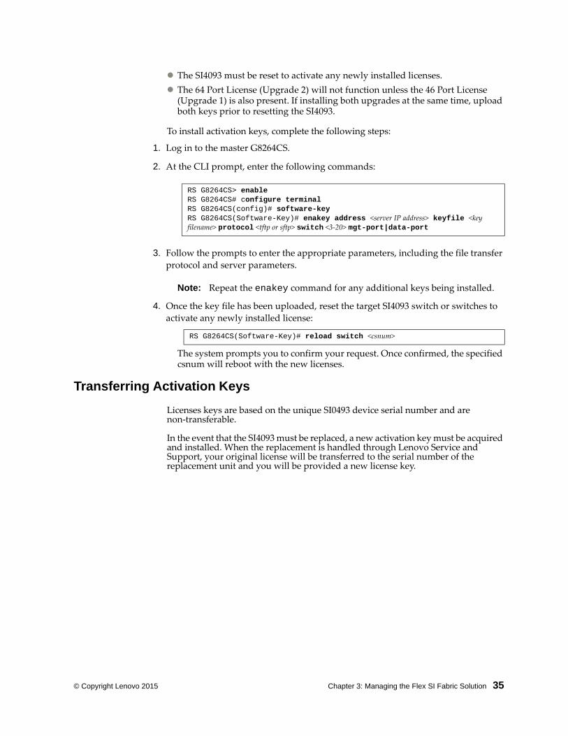
The SI4093 must be reset to activate any newly installed licenses.
The 64 Port License (Upgrade 2) will not function unless the 46 Port License (Upgrade 1) is also present. If installing both upgrades at the same time, upload both keys prior to resetting the SI4093.
To install activation keys, complete the following steps:
1. Log in to the master G8264CS.
2. At the CLI prompt, enter the following commands:
3. Follow the prompts to enter the appropriate parameters, including the file transfer
protocol and server parameters.
Note: Repeat the enakey command for any additional keys being installed.
4. Once the key file has been uploaded, reset the target SI4093 switch or switches to
activate any newly installed license:
The system prompts you to confirm your request. Once confirmed, the specified csnum will reboot with the new licenses.
Transferring Activation Keys
Licenses keys are based on the unique SI0493 device serial number and are non‐transferable.
In the event that the SI4093 must be replaced, a new activation key must be acquired and installed. When the replacement is handled through Lenovo Service and Support, your original license will be transferred to the serial number of the replacement unit and you will be provided a new license key.
RS G8264CS> enableRS G8264CS# configure terminalRS G8264CS(config)# softwarekeyRS G8264CS(SoftwareKey)# enakey address <server IP address> keyfile <key filename> protocol <tftp or sftp> switch <3‐20> mgtport|dataport
RS G8264CS(SoftwareKey)# reload switch <csnum>
36 Flex System Interconnect Fabric: Solution Guide
Managing Systems through Master and Backup G8264CS Switches
The SI Fabric is designed to enable master node and backup node between the G8264CS switches pair to provide continuous availability. All SI Fabric management is done using the master G8264CS switch. If the current master node fails, the current backup G8264CS switch will detect the absence of the master node and become the new master node of the SI Fabric. See “Configuring the SI Fabric Management IP Addresses and Gateway” on page 27 for details.
The Management IP address of the new master node is used to continue the resource management of the SI Fabric. If the data IP interface is used, the new master node will automatically assume the responsibility of resource management.
Note: If both the master and backup G8264CS switches fail, all Member SI4093 switches will also reset with all Internal server ports in disabled state and wait to rejoin the SI Fabric logical switch once the master G8264CS node recovers.
Deploying Staggered Image Upgrades for Master G8264CS Switch
The SI Fabric has a staggered mode for image upgrades. This staggered image upgrade provides network redundancy for the compute node, with redundant connection to its local SI4093 switches.
As with the traditional image upgrade process, the staggered upgrade downloads the SI Fabric boot image and OS software image to master node, and lets the master node push the new images to all member switches.
The staggered approach differs from the traditional image upgrade process in that instead of requiring a simultaneous reboot of the entire logical switch, the staggered update permits the master to reboot switches on a sequential basis.
Following is the staggered image upgrade sequence:
After the new boot image and OS image are downloaded and installed on all switches, the master node will reboot the backup node. The master node waits for the backup node to rejoin before it reboots itself to preserve failover capabilities to the current backup node.
After both new master and new backup nodes are booted with new image, the new master node will reboot all SI4093 switches in I/O module bay 1 of all Flex System chassis.
After all rebooted SI4093 switches rejoin, the new master node will reboot all SI4093 switches in IO Module bay 2 of all Flex System chassis. This rolling reboot will take place at all SI4093 switches in I/O module bay 3 then at all SI4093 switches in I/O Module bay 4.
Note: Boot image should be downloaded and installed, prior to downloading OS image via staggered upgrade.
During the staggered upgrade process, the compute node with redundant connection will ensure that at least one server link is available and prevents any server connectivity interruption.
© Copyright Lenovo 2015 Chapter 3: Managing the Flex SI Fabric Solution 37
Connecting Uplink to the Data Center Network
The SI Fabric provides uplink connection from both G8264CS switches to the data center network. The dual uplink feature provides layer‐2 loop‐free connectivity without the complexity of STP operation. The uplink connection can be a single physical interface, a static portchannel trunk group, a static LACP trunk group, or a hotlink pair.
When the SI Fabric is initially configured, all Ethernet ports that are not configured as SI Fabric ports at either G8264CS switches can be used as uplink connection. Initially, these Ethernet ports for uplink connection are placed in the Black‐hole VLAN, which prevents any network loop.
When an uplink connection is assigned to a target data VLAN or a set of target data VLANs from black‐hole VLAN (VLAN 4091 in this example), an uplink group is formed.
The SI Fabric, using the uplink group, stops other uplink connection from adding to this target data VLANs. The uplink group prevents any ingress traffic from looping back to data center network and allows the SI Fabric to operate without use of Spanning Tree Protocol (STP).
When an uplink connection is removed from its last data VLAN, the SI Fabric moves this uplink connection back to the Black‐hole VLAN and ensures no network loop.
The example below shows the commands and commented text for the uplink connection creation and assignments at the SI Fabric switches in IO Module bay 1 and bay 2 of the same Flex System chassis.
1. An uplink group is formed when the administrator configures an uplink
connection to a target data VLAN or a set of target data VLANs from the Black‐hole
VLAN. The uplink group in the SI Fabric prevents other uplink connection from
adding to this target data VLAN(s).
2. Configure interfaces and assign their data VLANs.
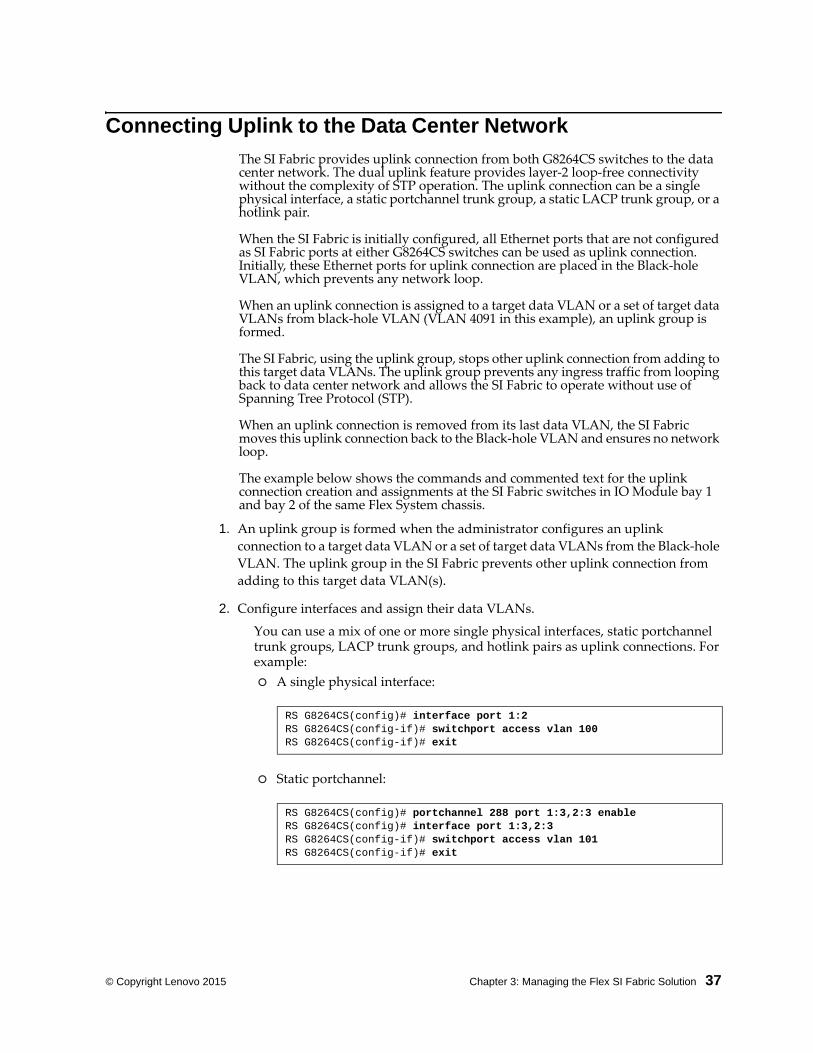
You can use a mix of one or more single physical interfaces, static portchannel trunk groups, LACP trunk groups, and hotlink pairs as uplink connections. For example:
A single physical interface:
Static portchannel:
RS G8264CS(config)# interface port 1:2RS G8264CS(configif)# switchport access vlan 100RS G8264CS(configif)# exit
RS G8264CS(config)# portchannel 288 port 1:3,2:3 enableRS G8264CS(config)# interface port 1:3,2:3RS G8264CS(configif)# switchport access vlan 101RS G8264CS(configif)# exit
38 Flex System Interconnect Fabric: Solution Guide
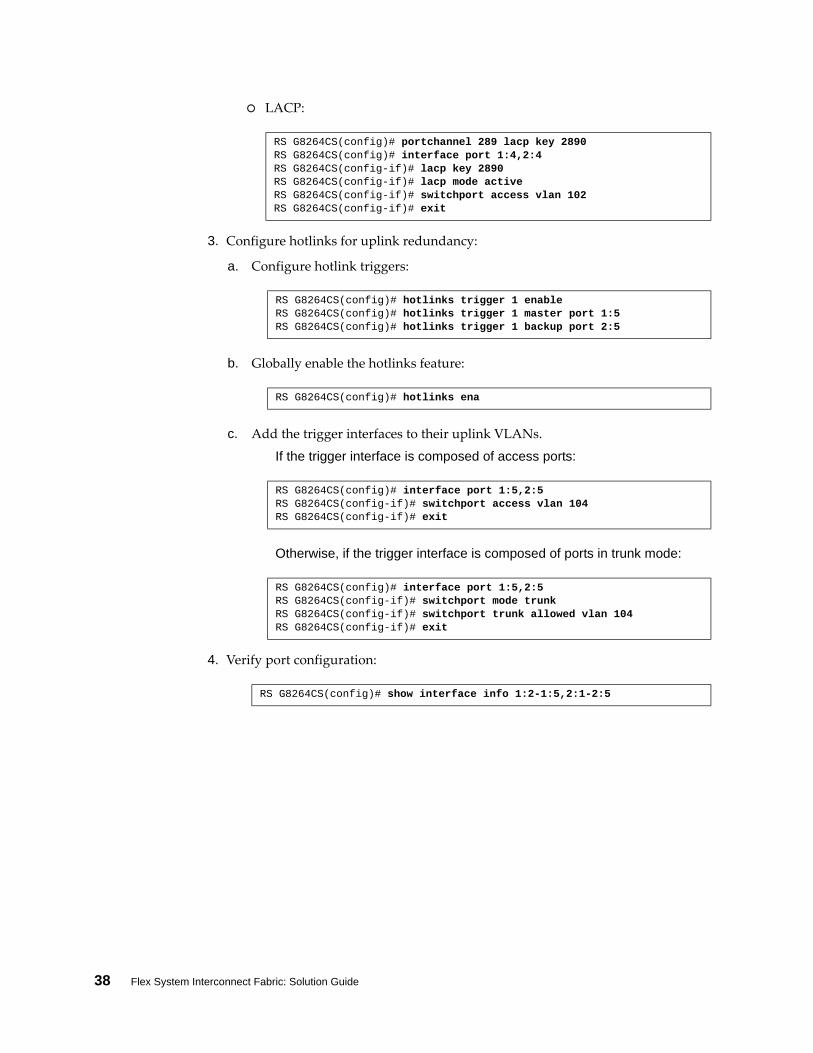
LACP:
3. Configure hotlinks for uplink redundancy:
a. Configure hotlink triggers:
b. Globally enable the hotlinks feature:
c. Add the trigger interfaces to their uplink VLANs.
If the trigger interface is composed of access ports:
Otherwise, if the trigger interface is composed of ports in trunk mode:
4. Verify port configuration:
RS G8264CS(config)# portchannel 289 lacp key 2890 RS G8264CS(config)# interface port 1:4,2:4RS G8264CS(configif)# lacp key 2890RS G8264CS(configif)# lacp mode activeRS G8264CS(configif)# switchport access vlan 102RS G8264CS(configif)# exit
RS G8264CS(config)# hotlinks trigger 1 enableRS G8264CS(config)# hotlinks trigger 1 master port 1:5RS G8264CS(config)# hotlinks trigger 1 backup port 2:5
RS G8264CS(config)# hotlinks ena
RS G8264CS(config)# interface port 1:5,2:5RS G8264CS(configif)# switchport access vlan 104RS G8264CS(configif)# exit
RS G8264CS(config)# interface port 1:5,2:5RS G8264CS(configif)# switchport mode trunkRS G8264CS(configif)# switchport trunk allowed vlan 104RS G8264CS(configif)# exit
RS G8264CS(config)# show interface info 1:21:5,2:12:5
© Copyright Lenovo 2015 Chapter 3: Managing the Flex SI Fabric Solution 39
Connecting Downlink Compute Nodes
The SI Fabric provides downlink connections from the SI4093 switches’ internal ports‐only compute nodes. Factory default settings configure all Internal ports on SI4093 switches for downlink connection in a default VLAN.
Note: If you assign downlink connections, the SI Fabric does not impose the uplink connection requirement mentioned previously.
The SI Fabric also supports the Unified Fabric Port (UFP) protocol between internal ports as downlink connections and server NICs. The downlink connection provisioning at the SI Fabric is similar to the common network provisioning at a stand‐alone SI4093 switch.
In order to maintain system redundancy, two SI4093 switches are used, installed in neighboring bays in the Flex System chassis: either Bay 1 and Bay 2, or alternately in Bay 3 and Bay 4. When you configure the SI4093 downlink connection to a compute node that has redundant NICs or NIC teaming, be sure that the switches and NICs are in the same chassis, and that the same internal port number is used in both paired SI4093 switches.
The example below shows the downlink connection creation and assignments at the SI Fabric logical switch made up by two G8264CS switches and two SI4093 switches in IO Module bay 1 and bay 2 of the same Flex System chassis.
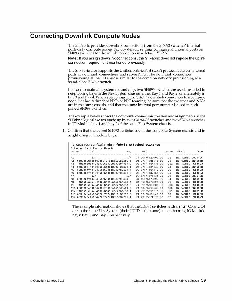
1. Confirm that the paired SI4093 switches are in the same Flex System chassis and in neighboring IO module bays.
The example information shows that the SI4093 switches with csnum C3 and C4 are in the same Flex System (their UUID is the same) in neighboring IO Module bays: Bay 1 and Bay 2 respectively.
RS G8264CS(config)# show fabric attachedswitchesAttached Switches in Fabric: asnum UUID Bay MAC csnum State TypeA1 N/A N/A 74:99:75:20:0e:00 C1 IN_FABRIC G8264CSA2 669d8dccfb95492bb727d18313c82289 3 08:17:f4:5f:40:00 C9 IN_FABRIC EN4093RA3 7fbaa95c6a484e0296c418cae2bbfe5a 2 08:17:f4:84:3b:00 C12 IN_FABRIC SI4093A4 c6b9ceff4440486cb65bd1e2e3fe3a94 1 08:17:f4:84:3d:00 C3 IN_FABRIC EN4093RA5 c6b9ceff4440486cb65bd1e2e3fe3a94 4 08:17:f4:84:40:00 C6 IN_FABRIC SI4093A6 c6b9ceff4440486cb65bd1e2e3fe3a94 3 08:17:f4:a7:55:00 C5 IN_FABRIC SI4093A7 N/A N/A 08:17:f4:fb:cc:00 C2 IN_FABRIC G8264CSA8 c6b9ceff4440486cb65bd1e2e3fe3a94 2 34:40:b5:73:92:00 C4 IN_FABRIC EN4093RA9 7fbaa95c6a484e0296c418cae2bbfe5a 4 34:40:b5:73:9c:00 C14 IN_FABRIC SI4093A10 7fbaa95c6a484e0296c418cae2bbfe5a 3 74:99:75:00:D1:00 C13 IN_FABRIC SI4093A11 b88989be60824783af6956a441cd0c61 3 74:99:75:1c:6b:00 C15 IN_FABRIC EN4093RA12 7fbaa95c6a484e0296c418cae2bbfe5a 1 74:99:75:1c:7d:00 C11 IN_FABRIC EN4093RA13 669d8dccfb95492bb727d18313c82289 2 74:99:75:5d:e1:00 C8 IN_FABRIC SI4093A14 669d8dccfb95492bb727d18313c82289 1 74:99:75:7f:7d:00 C7 IN_FABRIC SI4093
40 Flex System Interconnect Fabric: Solution Guide
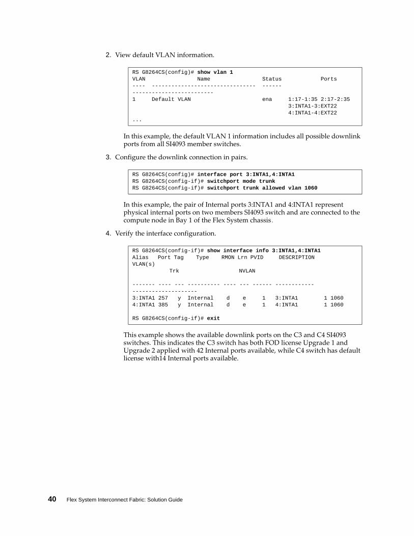
2. View default VLAN information.
In this example, the default VLAN 1 information includes all possible downlink ports from all SI4093 member switches.
3. Configure the downlink connection in pairs.
In this example, the pair of Internal ports 3:INTA1 and 4:INTA1 represent physical internal ports on two members SI4093 switch and are connected to the compute node in Bay 1 of the Flex System chassis.
4. Verify the interface configuration.
This example shows the available downlink ports on the C3 and C4 SI4093 switches. This indicates the C3 switch has both FOD license Upgrade 1 and Upgrade 2 applied with 42 Internal ports available, while C4 switch has default license with14 Internal ports available.
RS G8264CS(config)# show vlan 1VLAN Name Status Ports 1 Default VLAN ena 1:171:35 2:172:35 3:INTA13:EXT22 4:INTA14:EXT22...
RS G8264CS(config)# interface port 3:INTA1,4:INTA1RS G8264CS(configif)# switchport mode trunkRS G8264CS(configif)# switchport trunk allowed vlan 1060
RS G8264CS(configif)# show interface info 3:INTA1,4:INTA1Alias Port Tag Type RMON Lrn PVID DESCRIPTION VLAN(s) Trk NVLAN
3:INTA1 257 y Internal d e 1 3:INTA1 1 1060 4:INTA1 385 y Internal d e 1 4:INTA1 1 1060
RS G8264CS(configif)# exit
© Copyright Lenovo 2015 Chapter 3: Managing the Flex SI Fabric Solution 41
Connecting to Storage Resources
The SI Fabric provides integrated end‐to‐end FCoE storage connection with G864CS switches as FCoE gateways. This configuration bridges FCoE and Fibre Channel networks and SI4093 switches as FCoE aggregators. It connects FCoE enabled compute nodes and storage nodes with Converged Enhanced Ethernet (CEE) support.
With the Omni ports on G864CS switches, the SI Fabric can also provide native Fibre Channel (FC) connectivity to connect to existing SANs via port 1:53‐1:64 and 2:53‐2:64. The SI Fabric can serve as an NPV Gateway, which can uplink multiple Fibre Channel nodes to an existing full‐fabric SAN switch. It can also serve as FC‐BB‐5 compliant full‐fabric FC/FCoE SAN switch to connect to NPV Gateways or interconnecting Fibre Channel nodes.
E-Port Mode
In full‐fabric mode, the SI Fabric supports E_Port feature for up to four FC ISL links between G8264CS switches to expand fabric connectivity.
Follow these steps to enable FCoE function at the SI Fabric, comprised of two G8264CS switches and two SI4093 switches.
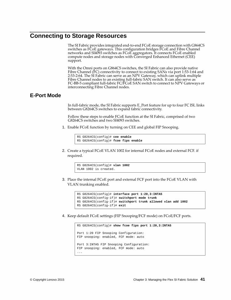
1. Enable FCoE function by turning on CEE and global FIP Snooping.
2. Create a typical FCoE VLAN 1002 for internal FCoE nodes and external FCF. if
required.
3. Place the internal FCoE port and external FCF port into the FCoE VLAN with
VLAN trunking enabled.
4. Keep default FCoE settings (FIP Snooping/FCF mode) on FCoE/FCF ports.
RS G8264CS(config)# cee enable RS G8264CS(config)# fcoe fips enable
RS G8264CS(config)# vlan 1002VLAN 1002 is created.
RS G8264CS(config)# interface port 1:20,3:INTA5RS G8264CS(configif)# switchport mode trunk RS G8264CS(configif)# switchport trunk allowed vlan add 1002RS G8264CS(configif)# exit
RS G8264CS(config)# show fcoe fips port 1:20,3:INTA5
Port 1:20 FIP Snooping Configuration:FIP snooping: enabled, FCF mode: auto
Port 3:INTA5 FIP Snooping Configuration:FIP snooping: enabled, FCF mode: auto...
42 Flex System Interconnect Fabric: Solution Guide
NPV Gateway Mode
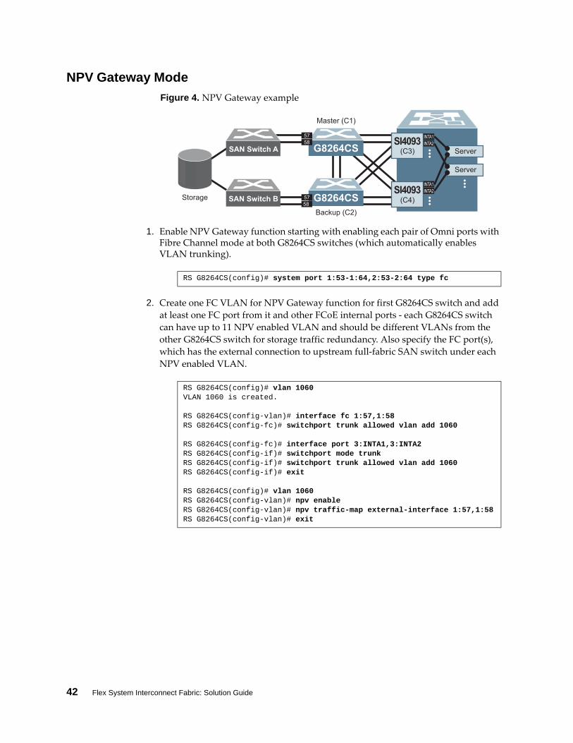
Figure 4. NPV Gateway example
1. Enable NPV Gateway function starting with enabling each pair of Omni ports with Fibre Channel mode at both G8264CS switches (which automatically enables VLAN trunking).
2. Create one FC VLAN for NPV Gateway function for first G8264CS switch and add
at least one FC port from it and other FCoE internal ports ‐ each G8264CS switch
can have up to 11 NPV enabled VLAN and should be different VLANs from the
other G8264CS switch for storage traffic redundancy. Also specify the FC port(s),
which has the external connection to upstream full‐fabric SAN switch under each
NPV enabled VLAN.
G8264CS SI4093Server
Server
SI4093G8264CS
5857
5758
INTA1INTA2
INTA2INTA1
Master (C1)
(C3)
(C4)
Backup (C2)
Storage SAN Switch B
SAN Switch A ......
...
RS G8264CS(config)# system port 1:531:64,2:532:64 type fc
RS G8264CS(config)# vlan 1060VLAN 1060 is created.
RS G8264CS(configvlan)# interface fc 1:57,1:58RS G8264CS(configfc)# switchport trunk allowed vlan add 1060
RS G8264CS(configfc)# interface port 3:INTA1,3:INTA2RS G8264CS(configif)# switchport mode trunkRS G8264CS(configif)# switchport trunk allowed vlan add 1060RS G8264CS(configif)# exit
RS G8264CS(config)# vlan 1060RS G8264CS(configvlan)# npv enableRS G8264CS(configvlan)# npv trafficmap externalinterface 1:57,1:58RS G8264CS(configvlan)# exit

© Copyright Lenovo 2015 Chapter 3: Managing the Flex SI Fabric Solution 43
3. Configure another NPV enabled VLAN for second G8264CS switch.
4. Verify NPV status.
RS G8264CS(config)# vlan 2060VLAN 1060 is created.
RS G8264CS(configvlan)# interface fc 2:57,2:58RS G8264CS(configfc)# switchport trunk allowed vlan add 2060
RS G8264CS(configfc)# interface port 4LINTA1,4:INTA2RS G8264CS(configif)# switchport mode trunk RS G8264CS(configif)# switchport trunk allowed vlan add 2060RS G8264CS(configif)# exit
RS G8264CS(config)# vlan 2060RS G8264CS(configvlan)# npv enableRS G8264CS(configvlan)# npv trafficmap externalinterface 2:57,2:58RS G8264CS(configvlan)# exit
RS G8264CS(config)# show npv statusUnit:1 VLAN: 1060 NPV enabledUnit:2 VLAN: 2060 NPV enabled
RS G8264CS(config)# show npv trafficmap VLAN Source Ports NPUplink Dest Ports 1060 empty 1:57,1:58 2060 empty 2:57,2:58
44 Flex System Interconnect Fabric: Solution Guide
Enabling Full-Fabric Function
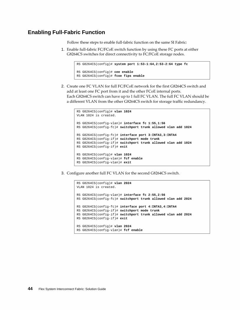
Follow these steps to enable full‐fabric function on the same SI Fabric:
1. Enable full‐fabric FC/FCoE switch function by using these FC ports at either G8264CS switches for direct connectivity to FC/FCoE storage nodes.
2. Create one FC VLAN for full FC/FCoE network for the first G8264CS switch and
add at least one FC port from it and the other FCoE internal ports.
Each G8264CS switch can have up to 1 full FC VLAN. The full FC VLAN should be
a different VLAN from the other G8264CS switch for storage traffic redundancy.
3. Configure another full FC VLAN for the second G8264CS switch.
RS G8264CS(config)# system port 1:531:64,2:532:64 type fc
RS G8264CS(config)# cee enable RS G8264CS(config)# fcoe fips enable
RS G8264CS(config)# vlan 1024VLAN 1024 is created.
RS G8264CS(configvlan)# interface fc 1:55,1:56RS G8264CS(configfc)# switchport trunk allowed vlan add 1024
RS G8264CS(configfc)# interface port 3:INTA3,3:INTA4RS G8264CS(configif)# switchport mode trunkRS G8264CS(configif)# switchport trunk allowed vlan add 1024RS G8264CS(configif)# exit
RS G8264CS(config)# vlan 1024RS G8264CS(configvlan)# fcf enableRS G8264CS(configvlan)# exit
RS G8264CS(config)# vlan 2024VLAN 1024 is created.
RS G8264CS(configvlan)# interface fc 2:55,2:56RS G8264CS(configfc)# switchport trunk allowed vlan add 2024
RS G8264CS(configfc)# interface port 4:INTA3,4:INTA4RS G8264CS(configif)# switchport mode trunk RS G8264CS(configif)# switchport trunk allowed vlan add 2024RS G8264CS(configif)# exit
RS G8264CS(config)# vlan 2024RS G8264CS(configvlan)# fcf enable
© Copyright Lenovo 2015 Chapter 3: Managing the Flex SI Fabric Solution 45
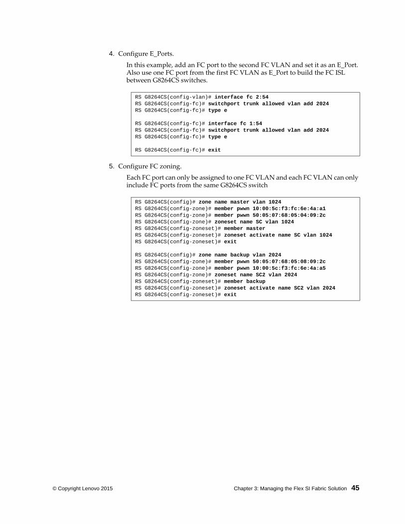
4. Configure E_Ports.
In this example, add an FC port to the second FC VLAN and set it as an E_Port. Also use one FC port from the first FC VLAN as E_Port to build the FC ISL between G8264CS switches.
5. Configure FC zoning.
Each FC port can only be assigned to one FC VLAN and each FC VLAN can only include FC ports from the same G8264CS switch
RS G8264CS(configvlan)# interface fc 2:54RS G8264CS(configfc)# switchport trunk allowed vlan add 2024RS G8264CS(configfc)# type e
RS G8264CS(configfc)# interface fc 1:54RS G8264CS(configfc)# switchport trunk allowed vlan add 2024RS G8264CS(configfc)# type e
RS G8264CS(configfc)# exit
RS G8264CS(config)# zone name master vlan 1024RS G8264CS(configzone)# member pwwn 10:00:5c:f3:fc:6e:4a:a1RS G8264CS(configzone)# member pwwn 50:05:07:68:05:04:09:2cRS G8264CS(configzone)# zoneset name SC vlan 1024RS G8264CS(configzoneset)# member masterRS G8264CS(configzoneset)# zoneset activate name SC vlan 1024RS G8264CS(configzoneset)# exit
RS G8264CS(config)# zone name backup vlan 2024RS G8264CS(configzone)# member pwwn 50:05:07:68:05:08:09:2cRS G8264CS(configzone)# member pwwn 10:00:5c:f3:fc:6e:4a:a5RS G8264CS(configzone)# zoneset name SC2 vlan 2024RS G8264CS(configzoneset)# member backupRS G8264CS(configzoneset)# zoneset activate name SC2 vlan 2024RS G8264CS(configzoneset)# exit

46 Flex System Interconnect Fabric: Solution Guide
© Copyright Lenovo 2015 Chapter 4: Flex SI Fabric -Specific ISCLI Commands 47
Chapter 4. Flex SI Fabric -Specific ISCLI Commands
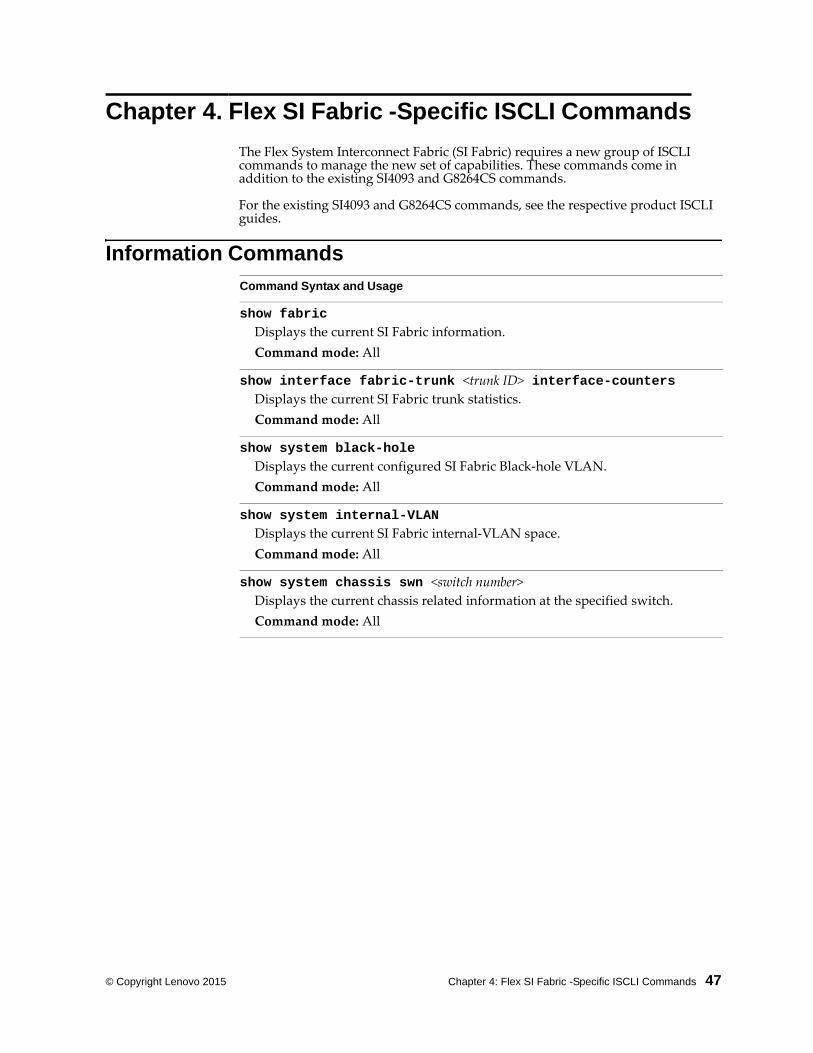
The Flex System Interconnect Fabric (SI Fabric) requires a new group of ISCLI commands to manage the new set of capabilities. These commands come in addition to the existing SI4093 and G8264CS commands.
For the existing SI4093 and G8264CS commands, see the respective product ISCLI guides.
Information Commands
Command Syntax and Usage
show fabricDisplays the current SI Fabric information.
Command mode: All
show interface fabrictrunk <trunk ID> interfacecountersDisplays the current SI Fabric trunk statistics.
Command mode: All
show system blackholeDisplays the current configured SI Fabric Black‐hole VLAN.
Command mode: All
show system internalVLANDisplays the current SI Fabric internal‐VLAN space.
Command mode: All
show system chassis swn <switch number>Displays the current chassis related information at the specified switch.
Command mode: All
48 Flex System Interconnect Fabric: Solution Guide
Configuration Commands
Command Syntax and Usage
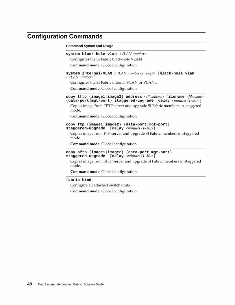
system blackhole vlan <VLAN number>Configures the SI Fabric black‐hole VLAN
Command mode: Global configuration
system internalVLAN <VLAN number or range> [blackhole vlan <VLAN number>]
Configures the SI Fabric internal VLAN or VLANs.
Command mode: Global configuration
copy tftp {image1|image2} address <IP address> filename <filename> {dataport|mgtport} staggeredupgrade [delay <minutes (1–30)>]
Copies image from TFTP server and upgrade SI Fabric members in staggered mode.
Command mode: Global configuration
copy ftp {image1|image2} {dataport|mgtport} staggeredupgrade [delay <minutes (1–30)>]
Copies image from FTP server and upgrade SI Fabric members in staggered mode.
Command mode: Global configuration
copy sftp {image1|image2} {dataport|mgtport} staggeredupgrade [delay <minutes (1–30)>]
Copies image from SFTP server and upgrade SI Fabric members in staggered mode.
Command mode: Global configuration
fabric bindConfigure all attached switch units.
Command mode: Global configuration

© Copyright Lenovo 2015 Chapter 4: Flex SI Fabric -Specific ISCLI Commands 49
IP Interface Configuration Commands
You can use the Command Line Interface (CLI) for making, viewing, and saving IP interface configuration changes.
Command Syntax and Usage
interface ip data {1|2}Enter Data IP interface mode.
Command mode: Global configuration
interface ip mgmt {ip|ipv6}Enter Management IP interface mode.
Command mode: Global configuration
mac <MAC address> ip address <IP address> <IP netmask> enableConfigure the IP address using dotted decimal notation.
Command mode: Interface IP (Management)
mac <MAC address> ipv6 address <IPv6 address> <IPv6 prefix> enableConfigure the IPv6 address using hexadecimal format with colons.
Command mode: Interface IP (Management)
show interface ip [data|mgmt]Displays the current IP interface settings.
Command mode: All
ip gateway data {ip|ipv6} address {<IPv4 address>|<IPv6 address>} enable
Configures the IP address of the default IP gateway over Data IP interface.
Command mode: Global configuration
ip gateway mgmt {ip|ipv6} mac <MAC address> address {<IPv4 address>|<IPv6 address>} enable
Configures the IP address of the default IP gateway over Management IP interface.
Command mode: Global configuration
show ip gateway {data|mgmt}Displays the current IP interface settings.
Command mode: All
50 Flex System Interconnect Fabric: Solution Guide
Software Key Commands
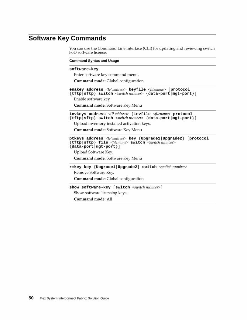
You can use the Command Line Interface (CLI) for updating and reviewing switch FoD software license.
Command Syntax and Usage
softwarekeyEnter software key command menu.
Command mode: Global configuration
enakey address <IP address> keyfile <filename> [protocol {tftp|sftp} switch <switch number> {dataport|mgtport}]
Enable software key.
Command mode: Software Key Menu
invkeys address <IP address> [invfile <filename> protocol {tftp|sftp} switch <switch number> {dataport|mgtport}]
Upload inventory installed activation keys.
Command mode: Software Key Menu
ptkeys address <IP address> key {Upgrade1|Upgrade2} [protocol {tftp|sftp} file <filename> switch <switch number> {dataport|mgtport}]
Upload Software Key.
Command mode: Software Key Menu
rmkey key {Upgrade1|Upgrade2} switch <switch number>Remove Software Key.
Command mode: Global configuration
show softwarekey [switch <switch number>]Show software licensing keys.
Command mode: All
© Copyright Lenovo 2015 Chapter 4: Flex SI Fabric -Specific ISCLI Commands 51
Boot Options
To use following new Boot Options commands, you must be logged in to the switch as the administrator. The new Boot Options commands provide options for the SI Fabric.
Command Syntax and Usage
boot fabric sifabricdomain <domain number>Configures the SI Fabric domain number on switches. The same domain number needs to be applied on both switches to form the SI Fabric.
Command mode: Global configuration
boot fabric fabrictrunk <list of ports>Configures the ports used to connect the switch to the SI Fabric. Enter only 10Gb external ports.
Command mode: Global configuration
sifabric siferrup Turns on the ports that were disabled (errdis) during SI Fabric merger.
Command mode: Global configuration
show boot staggeredupgradeShow status of staggered upgrade of the member switches in the SI Fabric.
Command mode: All

52 Flex System Interconnect Fabric: Solution Guide
© Copyright Lenovo 2015 Appendix A: Getting Help and Technical Assistance 53
Appendix A. Getting Help and Technical Assistance
If you need help, service, or technical assistance or just want more information about Lenovo products, you will find a wide variety of sources available from Lenovo to assist you.
Use this information to obtain additional information about Lenovo and Lenovo products, and determine what to do if you experience a problem with your Lenovo system or optional device.
Note: This section includes references to IBM web sites and information about obtaining service. IBM is Lenovoʹs preferred service provider for the System x, Flex System, and NeXtScale System products.
Before you call, make sure that you have taken these steps to try to solve the problem yourself.
If you believe that you require warranty service for your Lenovo product, the service technicians will be able to assist you more efficiently if you prepare before you call.
Check all cables to make sure that they are connected.
Check the power switches to make sure that the system and any optional devices are turned on.
Check for updated software, firmware, and operating‐system device drivers for your Lenovo product. The Lenovo Warranty terms and conditions state that you, the owner of the Lenovo product, are responsible for maintaining and updating all software and firmware for the product (unless it is covered by an additional maintenance contract). Your service technician will request that you upgrade your software and firmware if the problem has a documented solution within a software upgrade.
If you have installed new hardware or software in your environment, check the IBM ServerProven website to make sure that the hardware and software is supported by your product.
Go to the IBM Support portal to check for information to help you solve the problem.
Gather the following information to provide to the service technician. This data will help the service technician quickly provide a solution to your problem and ensure that you receive the level of service for which you might have contracted.
Hardware and Software Maintenance agreement contract numbers, if applicable
Machine type number (Lenovo 4‐digit machine identifier)
Model number
Serial number
Current system UEFI and firmware levels
Other pertinent information such as error messages and logs

54 Flex System Interconnect Fabric: Solution Guide
Start the process of determining a solution to your problem by making the pertinent information available to the service technicians. The IBM service technicians can start working on your solution as soon as you have completed and submitted an Electronic Service Request.
You can solve many problems without outside assistance by following the troubleshooting procedures that Lenovo provides in the online help or in the Lenovo product documentation. The Lenovo product documentation also describes the diagnostic tests that you can perform. The documentation for most systems, operating systems, and programs contains troubleshooting procedures and explanations of error messages and error codes. If you suspect a software problem, see the documentation for the operating system or program.