Embed Size (px)
Citation preview
WATER PURFICATION 911-740 REV. l 1
SHURFLO® AQUA KING™INSTALLATION & OPERATION MANUAL
SHURflo's Marine Duty fresh Water Pumps were developed to endure the harsh marine environment. The patented design delivers smooth, consistent fl ow at all ranges of operation, while drawing low current. The balanced motor design incorporates precision ball bearings for long life, motor is equipped with an integral thermal breaker and U/l Marine listed. All Marine duty pumps have sealed switches and are fi nished with a Electro Coating to inhibit corrosion. Marine duty fresh water pumps are enclosed to prevent incidental moisture from entering and when installed correctly, Marine Duty fresh Water Pumps provide years of quiet operation.
GENERAL INFORMATION
SHURflo realizes that in many in-stances our pump is being installed as a replacement pump within an existing system. The following guides should be considered to achieve optimum pump operation.
MOUNTING
❚ The pump can be at the same level or below the water tank. It may be posi-tioned above the water tank if needed, as it is capable of a 6 ft.[1.8M] vertical prime. Horizontal inlet tubing will allow priming to 30 ft. [9 M].
❚ Consider a dry location that allows easy access if maintenance is required. The pump should not be located in an area of less than one cubic foot un-less adequate ventilation is provided. Excessive heat may trigger the integral thermal breaker and interrupt opera-tion. When the temperature drops the breaker will automatically reset and start operation. The pump can be mounted in any position. If mounting the pump vertically, the pump head should be in the down position.
ELECTRICAL
❚ The pump should be on a dedicated (individual) circuit protected by the specifi ed fuse indicated on the motor label.
❚ A U/l approved marine duty (ignition protected) switch rated at or above 15 amps is recommended and must inter-rupt current fl ow on the positive (+ red) lead.
❚ The pump must be grounded to a "known ground" (battery). The ground wire must be the same size (gauge/Mm2) as the positive wire.
❚ Wire size (gauge/Mm2) is based on the distance from the power source to the pump. Recommended size wire is #14 gauge [2.5mm2]. for lengths of 20-50ft. [6-15M] use #12 gauge [4 Mm2].
❚ The total current draw on the circuit must not exceed 15 amps. If the pump is used in conjunction with other compo-nents, overload current protection (fuse or circuit breaker) and wire size must be for the total amp requirement ofall devices on the circuit.
2
PLUMBING
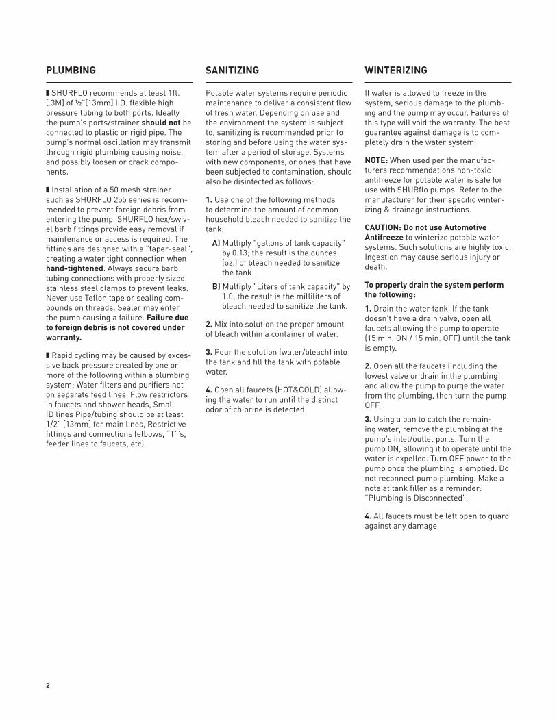
❚ SHURflo recommends at least 1ft. [.3M] of ½"[13mm] I.D. flexible high pressure tubing to both ports. Ideally the pump's ports/strainer should not be connected to plastic or rigid pipe. The pump's normal oscillation may transmit through rigid plumbing causing noise, and possibly loosen or crack compo-nents.
❚ Installation of a 50 mesh strainer such as SHURflo 255 series is recom-mended to prevent foreign debris from entering the pump. SHURflo hex/swiv-el barb fittings provide easy removal if maintenance or access is required. The fittings are designed with a "taper-seal", creating a water tight connection when hand-tightened. Always secure barb tubing connections with properly sized stainless steel clamps to prevent leaks. Never use Teflon tape or sealing com-pounds on threads. Sealer may enter the pump causing a failure. Failure due to foreign debris is not covered under warranty.
❚ Rapid cycling may be caused by exces-sive back pressure created by one or more of the following within a plumbing system: Water filters and purifiers not on separate feed lines, flow restrictors in faucets and shower heads, Small ID lines Pipe/tubing should be at least 1/2” [13mm] for main lines, Restrictive fittings and connections (elbows, “T”’s, feeder lines to faucets, etc).
SANITIZING
Potable water systems require periodic maintenance to deliver a consistent flow of fresh water. Depending on use and the environment the system is subject to, sanitizing is recommended prior to storing and before using the water sys-tem after a period of storage. Systems with new components, or ones that have been subjected to contamination, should also be disinfected as follows:
1. Use one of the following methods to determine the amount of common household bleach needed to sanitize the tank.
A) Multiply "gallons of tank capacity" by 0.13; the result is the ounces (oz.) of bleach needed to sanitize the tank.
B) Multiply "liters of tank capacity" by 1.0; the result is the milliliters of bleach needed to sanitize the tank.
2. Mix into solution the proper amount of bleach within a container of water.
3. Pour the solution (water/bleach) into the tank and fill the tank with potable water.
4. open all faucets (HoT&ColD) allow-ing the water to run until the distinct odor of chlorine is detected.
WINTERIZING
If water is allowed to freeze in the system, serious damage to the plumb-ing and the pump may occur. failures of this type will void the warranty. The best guarantee against damage is to com-pletely drain the water system.
NOTE: When used per the manufac-turers recommendations non-toxic antifreeze for potable water is safe for use with SHURflo pumps. Refer to the manufacturer for their specific winter-izing & drainage instructions.
CAUTION: Do not use Automotive Antifreeze to winterize potable water systems. Such solutions are highly toxic. Ingestion may cause serious injury or death.
To properly drain the system perform the following:
1. Drain the water tank. If the tank doesn't have a drain valve, open all faucets allowing the pump to operate (15 min. oN / 15 min. off) until the tank is empty.
2. open all the faucets (including the lowest valve or drain in the plumbing) and allow the pump to purge the water from the plumbing, then turn the pump off.
3. Using a pan to catch the remain-ing water, remove the plumbing at the pump's inlet/outlet ports. Turn the pump oN, allowing it to operate until the water is expelled. Turn off power to the pump once the plumbing is emptied. Do not reconnect pump plumbing. Make a note at tank filler as a reminder:"Plumbing is Disconnected".
4. All faucets must be left open to guard against any damage.
3
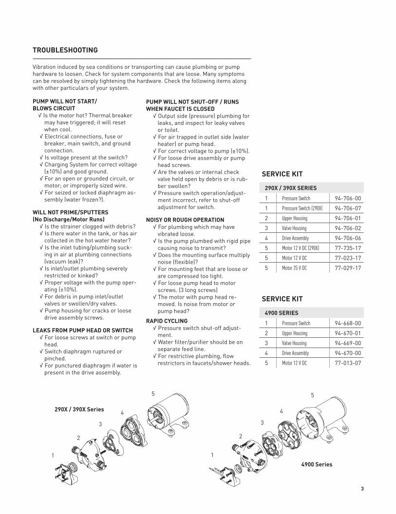
SERVICE KIT
290X / 390X SERIES
1 Pressure Switch 94-706-00
1 Pressure Switch (290X) 94-706-07
2 Upper Housing 94-706-01
3 Valve Housing 94-706-02
4 Drive Assembly 94-706-06
5 Motor 12 V DC (290X) 77-735-17
5 Motor 12 V DC 77-023-17
5 Motor 25 V DC 77-029-17
SERVICE KIT
4900 SERIES
1 Pressure Switch 94-668-00
2 Upper Housing 94-670-01
3 Valve Housing 94-669-00
4 Drive Assembly 94-670-00
5 Motor 12 V DC 77-013-07
TROUBLESHOOTING
PUMP WILL NOT START/BLOWS CIRCUIT
√ Is the motor hot? Thermal breaker may have triggered; it will reset when cool.
√ Electrical connections, fuse or breaker, main switch, and ground connection.
√ Is voltage present at the switch? √ Charging System for correct voltage
(±10%) and good ground. √ for an open or grounded circuit, or
motor; or improperly sized wire. √ for seized or locked diaphragm as-
sembly (water frozen?).
WILL NOT PRIME/SPUTTERS(No Discharge/Motor Runs)
√ Is the strainer clogged with debris? √ Is there water in the tank, or has air
collected in the hot water heater? √ Is the inlet tubing/plumbing suck-
ing in air at plumbing connections (vacuum leak)?
√ Is inlet/outlet plumbing severely restricted or kinked?
√ Proper voltage with the pump oper-ating (±10%).
√ for debris in pump inlet/outlet valves or swollen/dry valves.
√ Pump housing for cracks or loose drive assembly screws.
LEAKS FROM PUMP HEAD OR SWITCH √ for loose screws at switch or pump
head. √ Switch diaphragm ruptured or
pinched. √ for punctured diaphragm if water is
present in the drive assembly.
PUMP WILL NOT SHUT-OFF / RUNS WHEN FAUCET IS CLOSED
√ output side (pressure) plumbing for leaks, and inspect for leaky valves or toilet.
√ for air trapped in outlet side (water heater) or pump head.
√ for correct voltage to pump (±10%). √ for loose drive assembly or pump
head screws. √ Are the valves or internal check
valve held open by debris or is rub-ber swollen?
√ Pressure switch operation/adjust-ment incorrect, refer to shut-off adjustment for switch.
NOISY OR ROUGH OPERATION √ for plumbing which may have
vibrated loose. √ Is the pump plumbed with rigid pipe
causing noise to transmit? √ Does the mounting surface multiply
noise (flexible)? √ for mounting feet that are loose or
are compressed too tight. √ for loose pump head to motor
screws. (3 long screws) √ The motor with pump head re-
moved. Is noise from motor or pump head?
RAPID CYCLING √ Pressure switch shut-off adjust-
ment. √ Water filter/purifier should be on
separate feed line. √ for restrictive plumbing, flow
restrictors in faucets/shower heads.
Vibration induced by sea conditions or transporting can cause plumbing or pump hardware to loosen. Check for system components that are loose. Many symptoms can be resolved by simply tightening the hardware. Check the following items along with other particulars of your system.
4900 Series
290X / 390X Series
11
22
33
44
55
4
WATER PURIFICATION3545 HARboR GATEWAy SoUTH, SUITE 103, CoSTA MESA, CA 92626, (800) 854-3218 WWW.SHURflo.CoM
All Pentair trademarks and logos are owned by Pentair, Inc. All other brand or product names are trademarks or registered marks of their respective owners.because we are continuously improving our products and services, Pentair reserves the right to change specifications without prior notice.Pentair is an equal opportunity employer.
911-740 Rev. l 12/12 ©Pentair, Inc. All Rights Reserved.
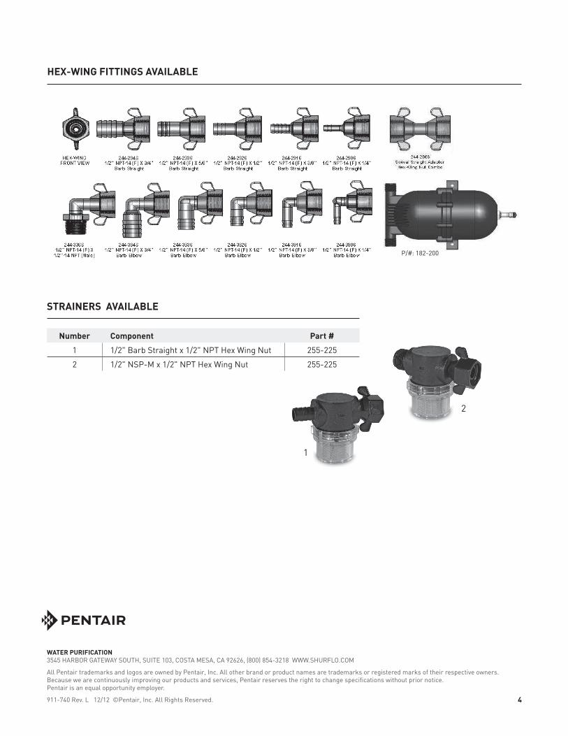
Number Component Part #
1 1/2" barb Straight x 1/2" NPT Hex Wing Nut 255-225
2 1/2" NSP-M x 1/2" NPT Hex Wing Nut 255-225
HEX-WING FITTINGS AVAILABLE
STRAINERS AVAILABLE
P/#: 182-200
1
2


![New Aqua Key Aqua Facts - Earth Observing System · 2017. 1. 26. · Earth Science Reference Handbook [ Missions: Aqua ] 73 Aqua Summary Aqua is a major international Earth Science](https://img.pdfslide.us/doc/110x75/604176e56ec9bf22204cde4b/new-aqua-key-aqua-facts-earth-observing-system-2017-1-26-earth-science-reference.jpg)