Embed Size (px)
Citation preview
User Manual
SHS800 Series Handheld Digital Oscilloscope
V1.2
SIGLENT TECHNOLOGIES CO,.LTD

SHS800 Series I
Declaration
1. Copyright © SIGLENT TECHNOLOGIES CO., LTD.
2. Information in this manual takes place of all data published before.
3. SIGLENT company reserves the rights to change specifications and price.
4. Contents in this manual are not allowed to be copied, extracted and
translated without permission by the company.

II SHS800 Series
Safety Information Carefully read the following safety information before using the SHS800.
Specific warning and caution statements, where they apply, appear throughout the manual.
A “Warning” identifies conditions and actions that pose hazard(s) to the user. A “Caution” identifies conditions and actions that the user should notice.
The following international symbols are used on the SHS800 and in this manual:
Hazardous Protective Warning Earth Ground Power
Voltage Earth Ground Switch
� Use only insulated voltage probes, test leads and adapters supplied with the SHS800, or accessories appointed by the company.
� Before use inspect voltage probes, test leads and accessories for mechanical damage and replace when damaged.
� Always connect the battery charge first to the AC outlet before connecting it to the SHS800.
� Do not apply voltages that higher than 600 V from earth ground to any input when using scope ports in a CAT environment. Do not apply voltages that higher than 1000 V from earth ground to any input when using scope ports in a CAT environment.
� Do not apply input voltages above the rating of the instrument. Use caution when using 1:1 test leads because the probe tip voltage will be directly transmitted to the SHS800.
� Do not apply voltages that higher than 300 V from earth ground to any input when using multimeter ports in a CAT environment. Do not apply voltages that higher than 600 V from earth ground to any input when using multimeter ports in a CAT environment.
� Do not apply voltages that higher than 300 V from earth ground to the isolated inputs when using multimeter ports in a CAT environment. Do not apply voltages that higher than 600 V from earth ground to the isolated inputs when using multimeter ports in a CAT environment.

SHS800 Series III
� Do not insert metal objects into connectors.
Use of the SHS800 in a manner not specified may impair the protection provided by the equipment. Before use, inspect the test leads for mechanical damage and replace damaged test leads!
Whenever it is likely that the safety has been impaired, the SHS800 must be turned off and disconnected from the line power. The matter should then be referred to qualified personnel.
Warning: Standard probe 10:1 supports CAT 400V.
Optional probe supports CAT 1000V and CAT 600V

IV SHS800 Series
Safety Operation of Battery SHS800 series handheld digital oscilloscope can be used to test float signal when power supplied by battery. When using the double channels to test float signal, the two channels should be connected to the same earth ground, because the earth ground of the two channels is connected
Warning: Do not connect the ground spring to voltages higher than 42 V peak or 30Vrms from earth ground.
Warning: Do not use USB line to connect SHS800 to any instruments (such as computer, printer and so on) which connected to the earth ground, or the SHS800 and the instruments connected with will be burned.
SHS800 Series V
Introduction of SHS800 Series This manual mainly introduces SHS800 series Handheld Digital Oscilloscope.
The SHS800 series is a high performance handheld oscilloscope with great range of dynamic input scope. It has small volume which convenient to carry, compact interface and etc. It satisfies the most needs of outside measurement and improves working efficiency greatly.
Function Characteristics
� The SHS800 combines the functions of oscilloscope, multimeter and recorder (including trend plot and waveform recorder) along with double channels.
� Oscilloscope channels input voltage grade: voltage inputs directly through a BNC probe is as high as CAT 300V and CAT 150v.
Standard probe: 10X CAT 400 Optional probe: 10X CAT 1000V and 10X CAT 600V Oscilloscope and multimeter safety grade is CAT 600V and CAT 300V
� 5.7 inches color TFT LCD.
� It provides maximal bandwidth 200MHz, real time sampling rate 1GSa/s, memory depth 2Mpts.
� The multimeter display resolution is 6000 points and can measure voltage, current, resistance, capacitance, diode, continuity.
� Support scope measure parameters trend plot, multimeter measure parameter trend plot and scope waveform recorder.
� 3 types of trigger mode: auto, normal and single; 5 types of trigger type: edge, pulse, video, slope and alternative.
� 32 types of auto-measurement function and 3 types of cursor measure mode.
� 5 kinds of digital filter mode: +, -, *, /, FFT.
� Unique digital filter function and waveform recording function.
� 2 groups of reference waveform, 20 groups of common waveform, 10 groups of setting inside save / recall; Support waveform, setting, CSV and bitmap file save and recall with USB flash driver.
� Standard configuration interface: USB Device, USB Host. Support software update with USB flash driver, PC remote control and PicBridge print.
� For its build-in Li battery and small volume, it’s convenient to carry and work outside.
VI SHS800 Series
Accessories of SHS800
� A user manual
� A product guaranty card
� A certification
� Two 1:1/10:1 probes
� An USB cable
� A adapter
� Meter pens for multimeter
� A Probes calibrated device
� A CD (including EasyScope3.0 computer software system)
Optional Probe
100MHz high-voltage safety probe CAT II 1000V,CAT II I 600V
SHS800 Series VII
Table of Contents
Safety Information..................................................................................................................... II
Safety Operation of Battery ....................................................................................................IV
Introduction of SHS800 Series................................................................................................ V
Function Characteristics ......................................................................................................... V Accessories of SHS800 .........................................................................................................VI
Chapter 1 Accidence.................................................................................................................. 1
Accidence of the Front Panel and User Interface ..................................................................1 Function Check......................................................................................................................... 4
Chapter 2 Using the Scope....................................................................................................... 5
Menu and Control Buttons ....................................................................................................... 5 Automatic Settings.................................................................................................................... 6 CH1/CH2 Channel Functions ..................................................................................................6 Scope’s Function Menu............................................................................................................ 9
Acquire Signals System ....................................................................................................9 Display System ................................................................................................................ 11 Math Waveform................................................................................................................ 13 Horizontal System............................................................................................................ 15 Reference waveform ....................................................................................................... 17
Cursor and Measure System ................................................................................................. 18 Cursor measure ............................................................................................................... 18 Parameter Measure ......................................................................................................... 20
Trigger System........................................................................................................................ 25 Save and Recall System........................................................................................................ 33 Utility System .......................................................................................................................... 37
Chapter 3 Using the Multimeter ............................................................................................. 43
Making DC and AC Voltage Measurement ........................................................................... 44 Making Resistance Measurement ......................................................................................... 45 Making Diode Measurement.................................................................................................. 46 Making Continuity Measurement........................................................................................... 46 Making Capacitance Measurement....................................................................................... 47 Making DC and AC Current Measurement ........................................................................... 48
Chapter 4 Using the Recorder Functions ............................................................................ 50
Oscilloscope Trend Plot ......................................................................................................... 51 Waveform Recorder ............................................................................................................... 54 Multimeter Trend Plot ............................................................................................................. 57
Chapter 5 Prompting and Troubleshooting ......................................................................... 60
System Prompting Messages Instruction ............................................................................. 60 Troubleshooting ...................................................................................................................... 62

VIII SHS800 Series
Chapter 6 Service and Support.............................................................................................. 64
Maintain Summary.................................................................................................................. 64 Contact with SIGLENT ........................................................................................................... 64
Appendix A: Specifications .................................................................................................... 65
Appendix B: Default Setup ..................................................................................................... 72
Appendix C: Battery Installation............................................................................................ 74
Appendix D: Daily Maintaining and Cleaning ...................................................................... 75
SHS800 Series 1
Chapter 1 Accidence About this Chapter This chapter mainly covers the following contents:
� Get a primary understanding of the front panel and user interface
� A brief function check
� Probe compensation
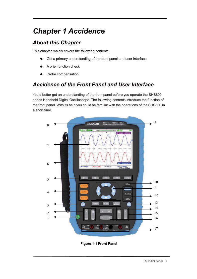
Accidence of the Front Panel and User Interface
You’d better get an understanding of the front panel before you operate the SHS800 series Handheld Digital Oscilloscope. The following contents introduce the function of the front panel. With its help you could be familiar with the operations of the SHS800 in a short time.
Figure 1-1 Front Panel
12
3
4
5
6
7
89
1011
12
131415
17
16
2 SHS800 Series
Description
1. power on/off key 2. CH1 vertical range and position key 3. CH1 on /off key 4. Scope, Meter, Recorder function
menu 5. option keys 6. Handle 7. LCD 8. LOGO 9. BW and sample rate
10. menu on/off key 11. arrow keys 12. Auto, Run/Stop, Cursor function
keys 13. CH2 on/off key 14. Trigger, User, Save/Recall function
keys 15. CH2 vertical range and position keys 16. time base and horizon position keys 17. multimeter input ports
Notes:
The arrow keys include these functions: direction keys, moving trigger level, setting the trigger level to zero, choosing menu, setting horizontal position to zero, moving cursor.
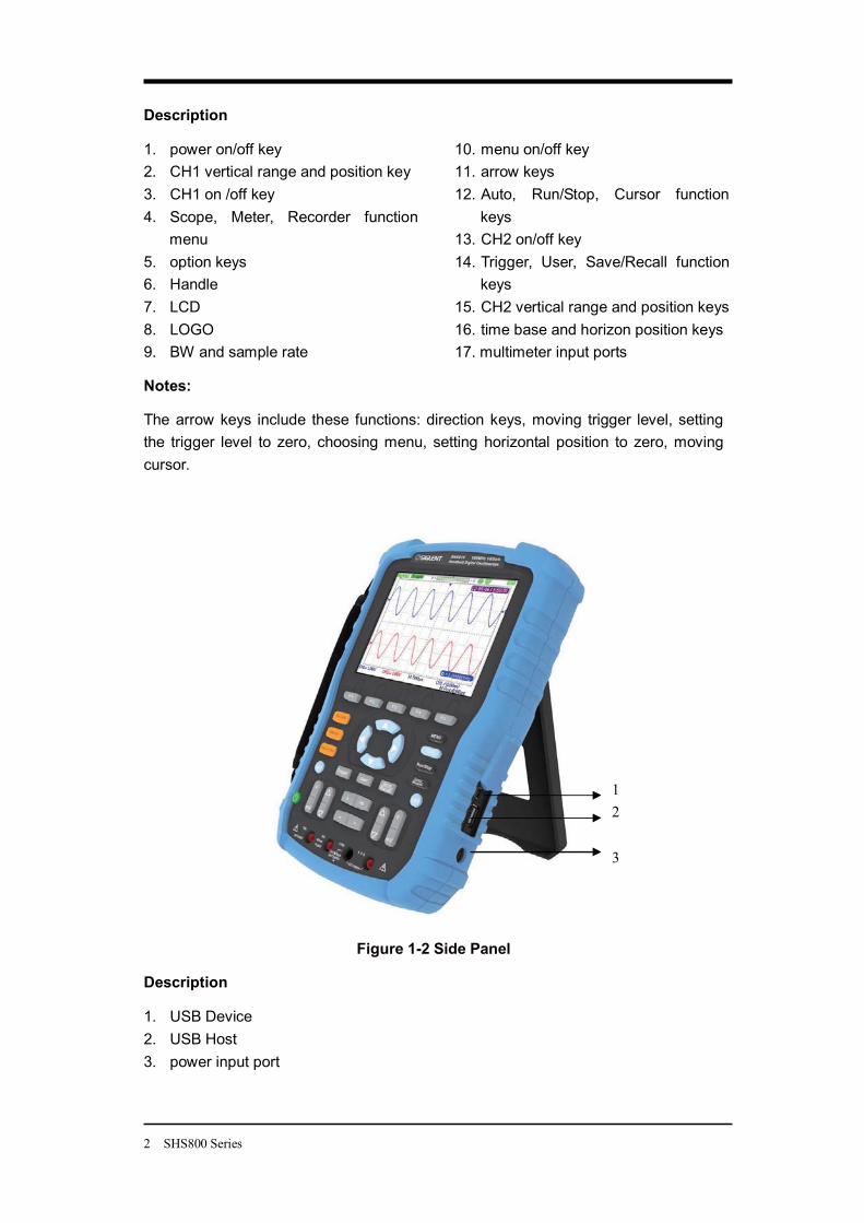
Figure 1-2 Side Panel
Description
1. USB Device 2. USB Host 3. power input port
12
3
SHS800 Series 3
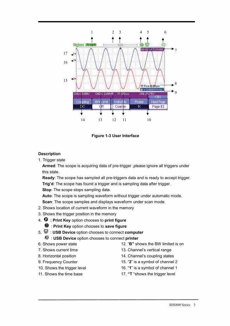
Figure 1-3 User Interface
Description 1. Trigger state
Armed: The scope is acquiring data of pre-trigger ,please ignore all triggers under this state. Ready: The scope has sampled all pre-triggers data and is ready to accept trigger. Trig’d: The scope has found a trigger and is sampling data after trigger. Stop: The scope stops sampling data. Auto: The scope is sampling waveform without trigger under automatic mode. Scan: The scope samples and displays waveform under scan mode.
2. Shows location of current waveform in the memory 3. Shows the trigger position in the memory 4. : Print Key option chooses to print figure
: Print Key option chooses to save figure 5. : USB Device option chooses to connect computer
: USB Device option chooses to connect printer 6. Shows power state 7. Shows current time 8. Horizontal position 9. Frequency Counter 10. Shows the trigger level 11. Shows the time base
12. “B” shows the BW limited is on 13. Channel’s vertical range 14. Channel’s coupling states 15. “2” is a symbol of channel 2 16. “1” is a symbol of channel 1 17. “T “shows the trigger level
1 2 3 4 5 6
7
8
9
10 11 12 13 14
15
16
17
4 SHS800 Series
Function Check and Probe Compensation
Function Check
Let’s make a quick function check to make sure whether the SHS800 works normally. Please do the following steps:
1. Power the SHS800. The SHS800 performs all the self check items and makes sure that it passes the self check.
2. Connect the probe to the CH1 of the SHS800. Align the slot of the probe connector with the salient on the CH1 BNC, push down and twist right to lock the probe. Connect the probe tip and reference lead to the Probe Comp connectors.
3. Press Auto , you will see a square wave with 1 KHz frequency and about 3V peak-peak in a few seconds.
4. Press CH1 twice to cancel channel 1, then press CH2 to display channel 2 and repeat step 2 and 3.
Probe Compensation
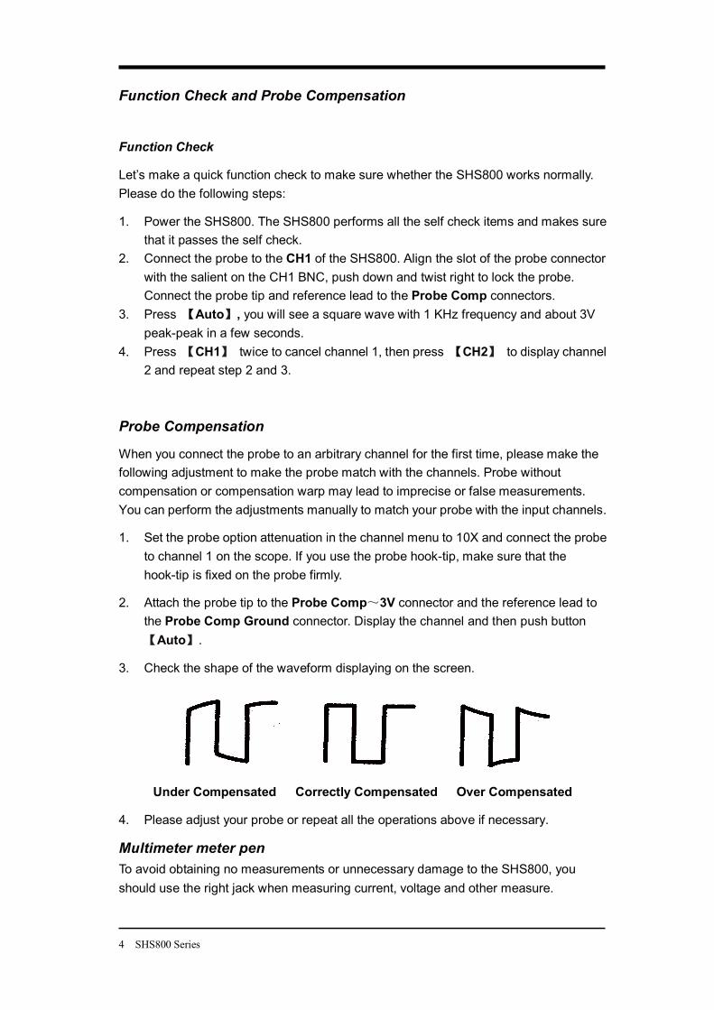
When you connect the probe to an arbitrary channel for the first time, please make the following adjustment to make the probe match with the channels. Probe without compensation or compensation warp may lead to imprecise or false measurements. You can perform the adjustments manually to match your probe with the input channels.
1. Set the probe option attenuation in the channel menu to 10X and connect the probe to channel 1 on the scope. If you use the probe hook-tip, make sure that the hook-tip is fixed on the probe firmly.
2. Attach the probe tip to the Probe Comp 3V connector and the reference lead to the Probe Comp Ground connector. Display the channel and then push button
Auto .
3. Check the shape of the waveform displaying on the screen.
Under Compensated Correctly Compensated Over Compensated
4. Please adjust your probe or repeat all the operations above if necessary.
Multimeter meter pen To avoid obtaining no measurements or unnecessary damage to the SHS800, you should use the right jack when measuring current, voltage and other measure.
SHS800 Series 5
Chapter 2 Using the Scope About this Chapter
This chapter provides a step-by-step introduction to the scope functions of SHS800 series. The introduction gives basic examples to show how to use the menus and perform basic operations without d covering all of the capabilities of the scope functions
In order to use the SHS800 effectively, we need to know the functions of the SHS800 below. Menu and control buttons, connector and control, auto-settings, Scope, measurement system, trigger system, storage system and utility system.
Menu and Control Buttons
Table 2-1 Function Menu CH1, CH2 channel menu
Acquire sample menu Display display menu Math math menu
Horizon horizon menu Ref reference waveform menu
MEAU on/off menu Auto automatic setting control menu
Run/Stop sample/Stop button Cursor cursor menu
Measure automatic measurement menu Trigger trigger menu
Save/Recall save/Recall menu User utility menu
6 SHS800 Series
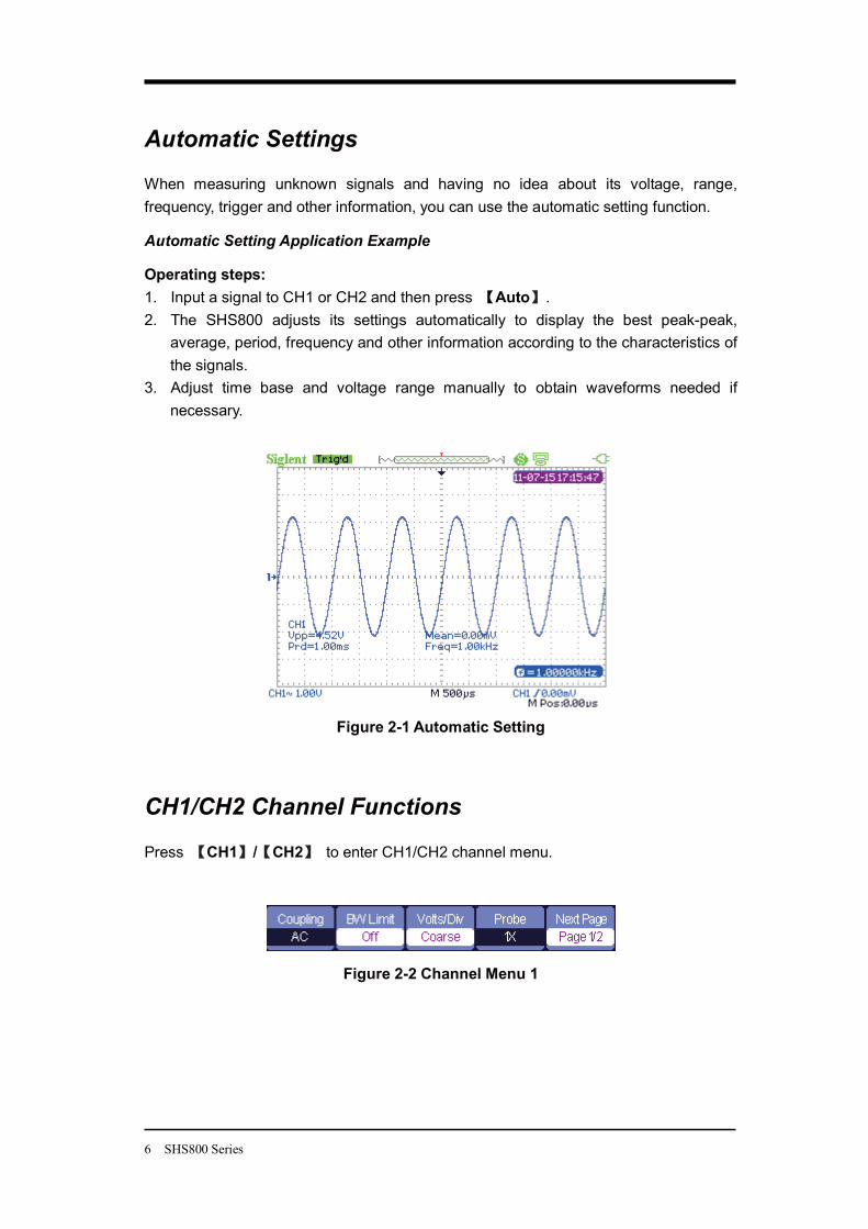
Automatic Settings
When measuring unknown signals and having no idea about its voltage, range, frequency, trigger and other information, you can use the automatic setting function.
Automatic Setting Application Example
Operating steps: 1. Input a signal to CH1 or CH2 and then press Auto . 2. The SHS800 adjusts its settings automatically to display the best peak-peak,
average, period, frequency and other information according to the characteristics of the signals.
3. Adjust time base and voltage range manually to obtain waveforms needed if necessary.
Figure 2-1 Automatic Setting
CH1/CH2 Channel Functions
Press CH1 / CH2 to enter CH1/CH2 channel menu.
Figure 2-2 Channel Menu 1
SHS800 Series 7
Table 2-2 CH1/CH2 function Menu 1 Option Setting Instruction
DC DC passes both AC and DC components of the input signals.
AC AC blocks the DC component of the input signals and attenuates signals below 10 Hz.
Coupling
GND GND disconnects the input signal.
BW Limit On Off
Limit the bandwidth above 20M to reduce display noise; filter the signals to reduce noise and other unwanted high frequency components.
Coarse Change the range of voltage by .1-2-5 sequence.
V/div Fine
Fine changes the resolution by small steps under the coarse settings.
Probe 1X 5X 10X 50X100X 500X 1000X
Set to match the type of probe you are using to ensure correct vertical readouts.
Next Page Page1/2 Enter the second page of CH1/CH2 menu.
Figure 2-3 Channel Menu 2
Table 2-3 CH1/CH2 Function Menu 2 Option Setting Instruction Invert On/Off Turn on/off invert function. Filter Enter the FILTER menu.
To Zero Set waveform vertical position and trigger level to zero. Next Page Page 2/2 Return to the first page of CH1/CH2 menu.
Figure 2-4 Digital Filter Function Menu
8 SHS800 Series
Table 2-4 Digital Filter Function Menu Option Setting Introduction
On Turn on the digital filter. Digital Filter
Off Turn off the digital filter.
Type
Setup as LPF (Low Pass Filter). Setup as HPF (High Pass Filter). Setup as BPF (Band Pass Filter). Setup as BRF (Band Reject Filter).
Up_Limit Use the up and down arrow keys to set Upp_Limit.
Low_Limit Use the up and down arrow keys to set Low_Limit.
Return Return to the CH1 or CH2 menu.
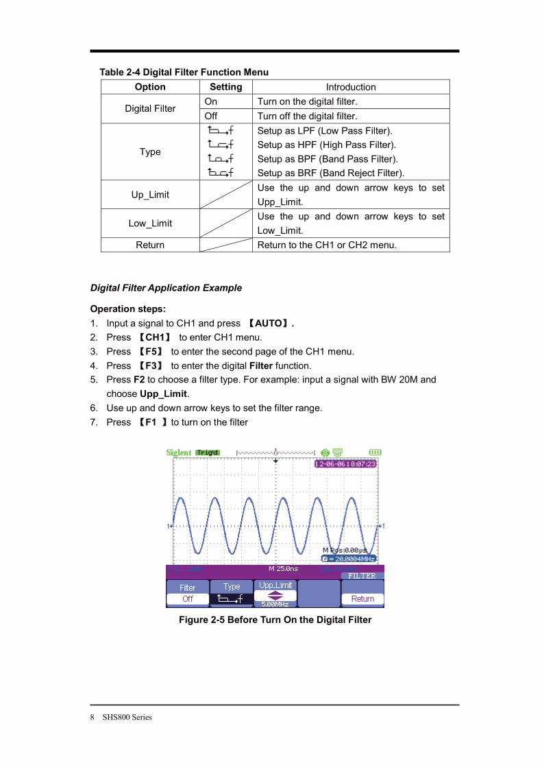
Digital Filter Application Example
Operation steps: 1. Input a signal to CH1 and press AUTO . 2. Press CH1 to enter CH1 menu. 3. Press F5 to enter the second page of the CH1 menu. 4. Press F3 to enter the digital Filter function. 5. Press F2 to choose a filter type. For example: input a signal with BW 20M and
choose Upp_Limit. 6. Use up and down arrow keys to set the filter range. 7. Press F1 to turn on the filter
Figure 2-5 Before Turn On the Digital Filter
SHS800 Series 9
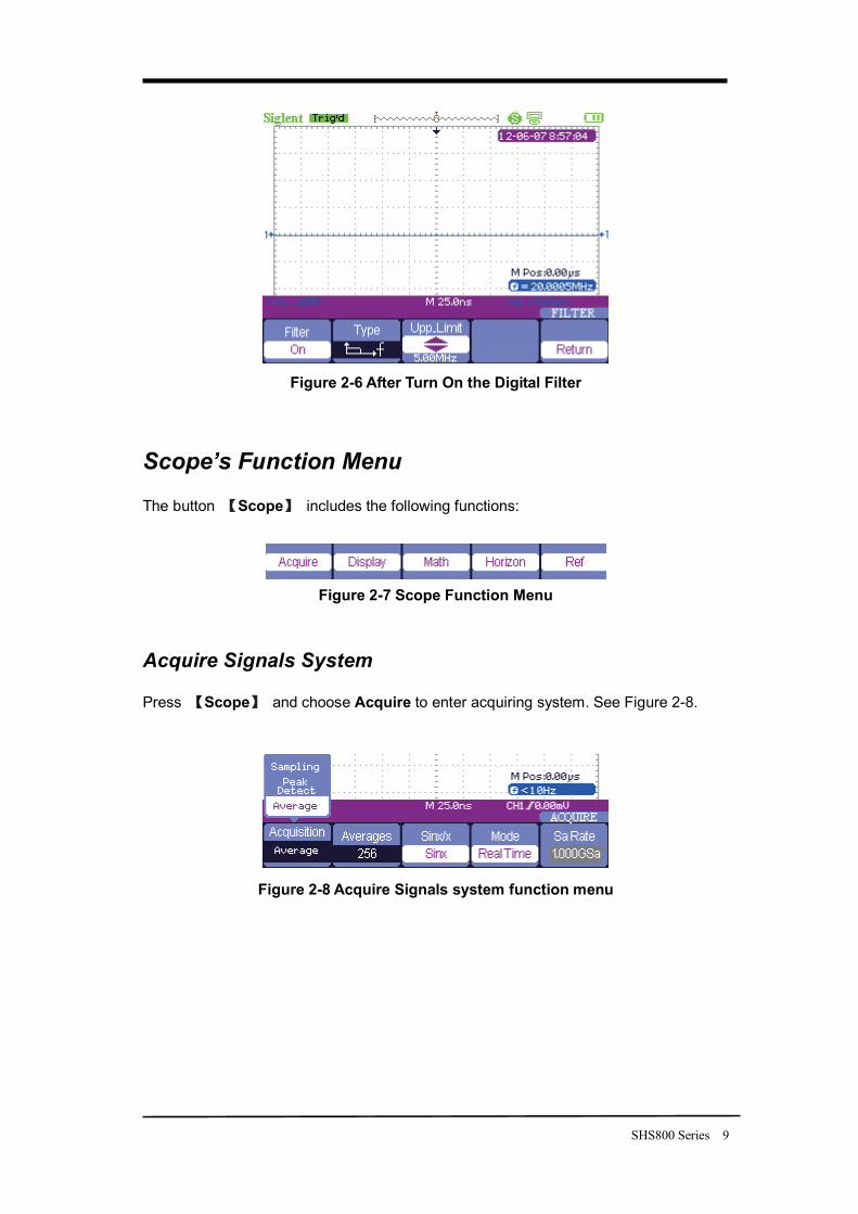
Figure 2-6 After Turn On the Digital Filter
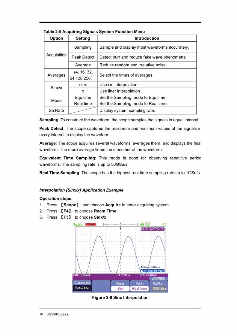
Scope’s Function Menu
The button Scope includes the following functions:
Figure 2-7 Scope Function Menu
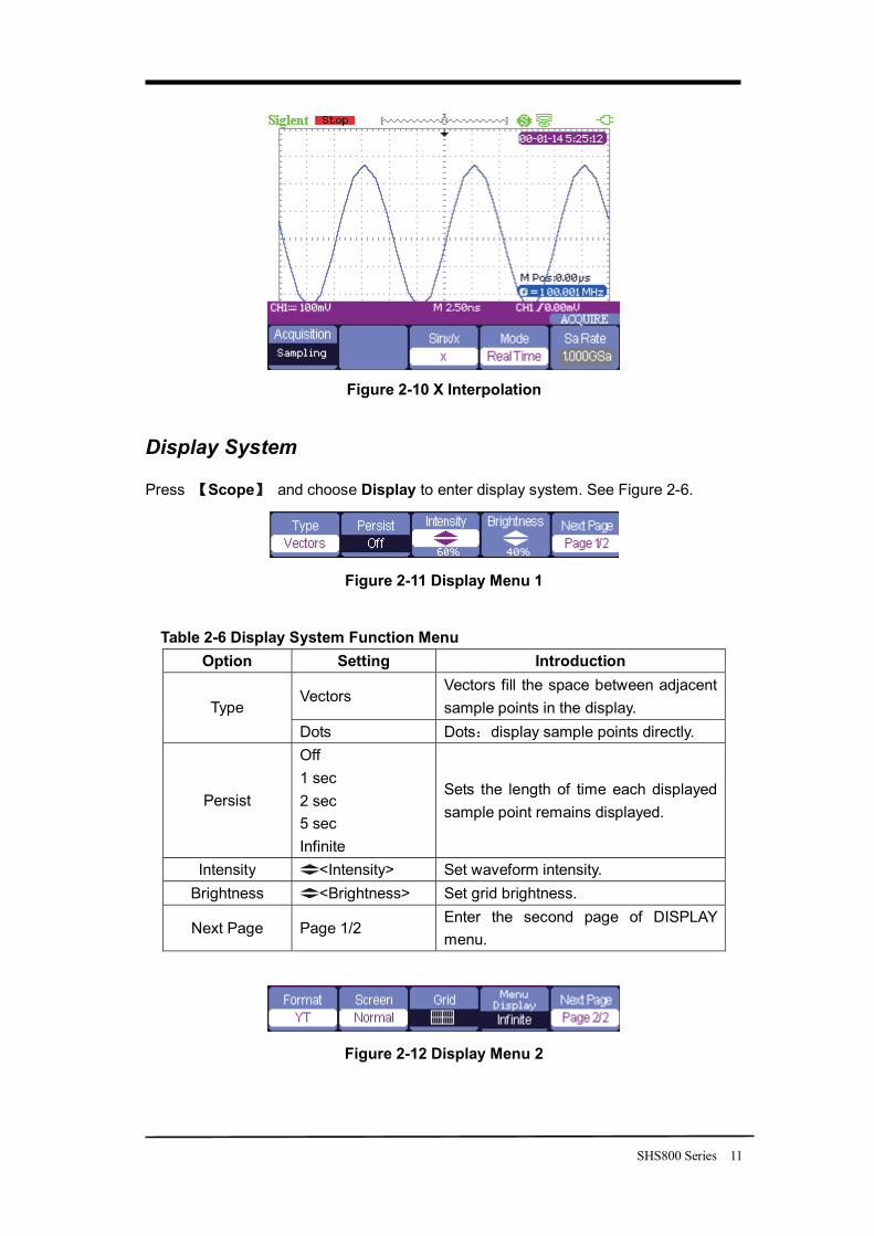
Acquire Signals System
Press Scope and choose Acquire to enter acquiring system. See Figure 2-8.
Figure 2-8 Acquire Signals system function menu
10 SHS800 Series
Table 2-5 Acquiring Signals System Function Menu Option Setting Introduction
Sampling Sample and display most waveforms accurately.
Peak Detect Detect burr and reduce fake wave phenomena. Acquisition
Average Reduce random and irrelative noise.
Averages (4, 16, 32,
64,128,256 Select the times of averages.
sinx Use sin interpolation Sinx/x
x Use liner interpolation
Mode Equ time Real time
Set the Sampling mode to Equ time. Set the Sampling mode to Real time.
Sa Rate Display system sampling rate.
Sampling: To construct the waveform, the scope samples the signals in equal interval.
Peak Detect: The scope captures the maximum and minimum values of the signals in every interval to display the waveform.
Average: The scope acquires several waveforms, averages them, and displays the final waveform. The more average times the smoother of the waveform.
Equivalent Time Sampling: This mode is good for observing repetitive period waveforms. The sampling rate is up to 50GSa/s.
Real Time Sampling: The scope has the highest real-time sampling rate up to 1GSa/s.
Interpolation (Sinx/x) Application Example
Operation steps: 1. Press Scope and choose Acquire to enter acquiring system. 2. Press F4 to choose Ream Time. 3. Press F3 to choose Sinx/x.
Figure 2-9 Sinx Interpolation
SHS800 Series 11
Figure 2-10 X Interpolation
Display System
Press Scope and choose Display to enter display system. See Figure 2-6.
Figure 2-11 Display Menu 1
Table 2-6 Display System Function Menu Option Setting Introduction
Vectors Vectors fill the space between adjacent sample points in the display. Type
Dots Dots display sample points directly.
Persist
Off 1 sec 2 sec 5 sec Infinite
Sets the length of time each displayed sample point remains displayed.
Intensity <Intensity> Set waveform intensity. Brightness <Brightness> Set grid brightness.
Next Page Page 1/2 Enter the second page of DISPLAY menu.
Figure 2-12 Display Menu 2
12 SHS800 Series
Table 2-7 Display system function menu 2: Option Setting Introduction
YT YT format displays the vertical voltage in relation to time (horizontal scale).
Format XY
XY format displays a dot each time a sample is acquired on channel 1 and channel 2.
Normal Set to normal mode. Screen
Inverted Set to invert color display mode.
Grid Display grids and axes on the screen.
Turn off the grids. Turn off the grids and axes.
Menu Display
2sec, 5sec, 10sec, 20sec, Infinite
Set display time of menu on the screen.
Next Page Page 2/2 Return to the first page of DISPLAY menu.
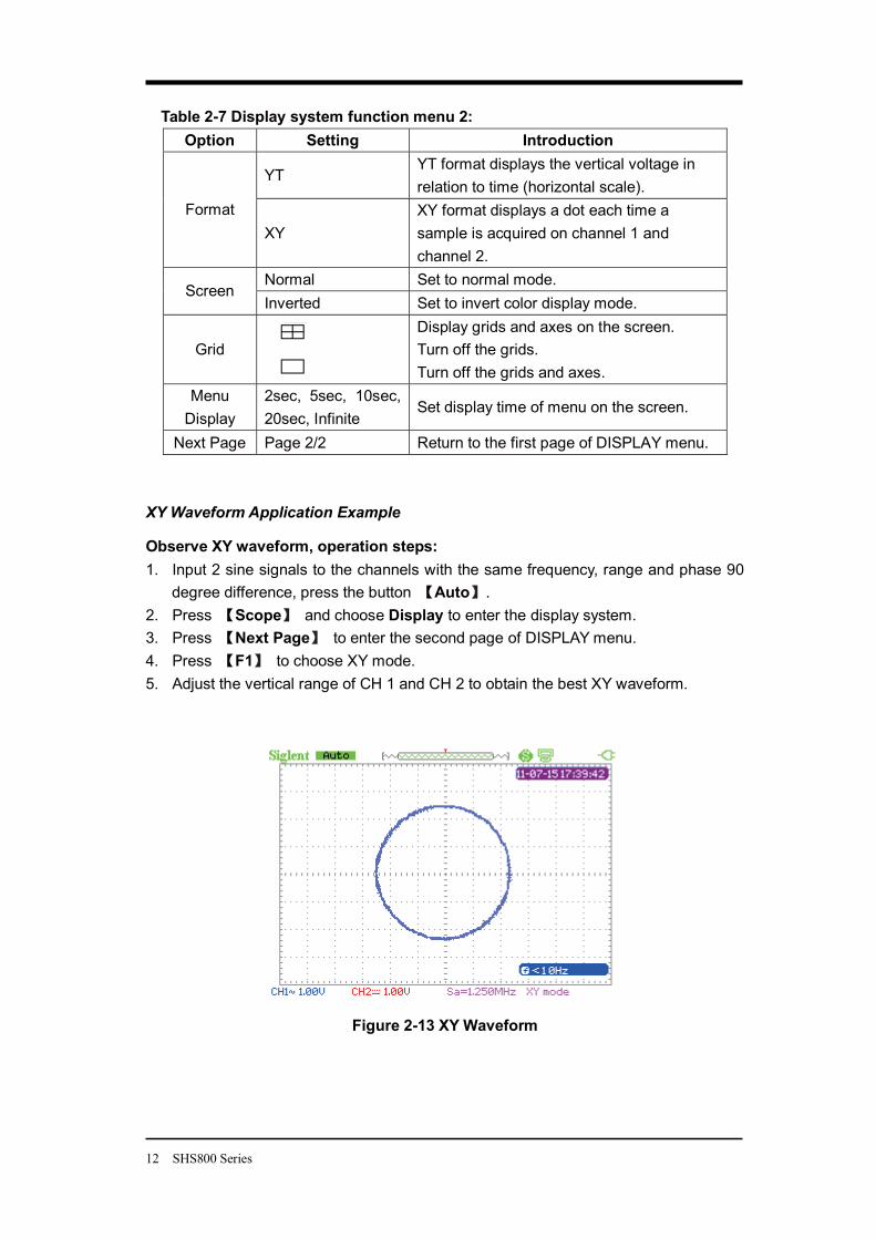
XY Waveform Application Example
Observe XY waveform, operation steps: 1. Input 2 sine signals to the channels with the same frequency, range and phase 90
degree difference, press the button Auto . 2. Press Scope and choose Display to enter the display system. 3. Press Next Page to enter the second page of DISPLAY menu. 4. Press F1 to choose XY mode. 5. Adjust the vertical range of CH 1 and CH 2 to obtain the best XY waveform.
Figure 2-13 XY Waveform
SHS800 Series 13
Math Waveform
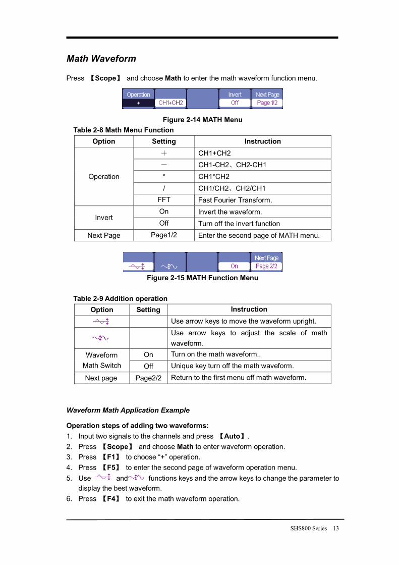
Press Scope and choose Math to enter the math waveform function menu.
Figure 2-14 MATH Menu Table 2-8 Math Menu Function
Option Setting Instruction CH1+CH2 CH1-CH2 CH2-CH1
* CH1*CH2 / CH1/CH2 CH2/CH1
Operation
FFT Fast Fourier Transform. On Invert the waveform.
Invert Off Turn off the invert function
Next Page Page1/2 Enter the second page of MATH menu.
Figure 2-15 MATH Function Menu
Table 2-9 Addition operation
Option Setting Instruction
Use arrow keys to move the waveform upright.
Use arrow keys to adjust the scale of math waveform.
On Turn on the math waveform.. Waveform Math Switch Off Unique key turn off the math waveform.
Next page Page2/2 Return to the first menu off math waveform.
Waveform Math Application Example
Operation steps of adding two waveforms: 1. Input two signals to the channels and press Auto . 2. Press Scope and choose Math to enter waveform operation. 3. Press F1 to choose “+” operation. 4. Press F5 to enter the second page of waveform operation menu. 5. Use and functions keys and the arrow keys to change the parameter to
display the best waveform. 6. Press F4 to exit the math waveform operation.
14 SHS800 Series
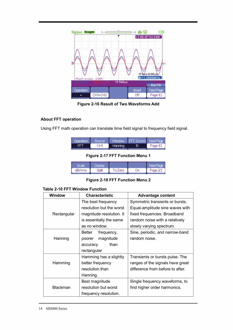
Figure 2-16 Result of Two Waveforms Add
About FFT operation
Using FFT math operation can translate time field signal to frequency field signal.
Figure 2-17 FFT Function Menu 1
Figure 2-18 FFT Function Menu 2
Table 2-10 FFT Window Function Window Characteristic Advantage content
Rectangular
The best frequency resolution but the worst magnitude resolution. It is essentially the same as no window.
Symmetric transients or bursts. Equal-amplitude sine waves with fixed frequencies. Broadband random noise with a relatively slowly varying spectrum.
Hanning
Better frequency, poorer magnitude accuracy than rectangular
Sine, periodic, and narrow-band random noise.
Hamming
Hamming has a slightly better frequency resolution than Hanning.
Transients or bursts pulse. The ranges of the signals have great difference from before to after.
Blackman
Best magnitude resolution but worst frequency resolution.
Single frequency waveforms, to find higher order harmonics.
SHS800 Series 15
FFT Zoom: zoom in FFT waveform vertically by 1X, 2X, 5X and 10X.
Scale: choose dBVrms or Vrms as a measure unit.
Display: Spilt or Full Screen FFT waveform display mode.
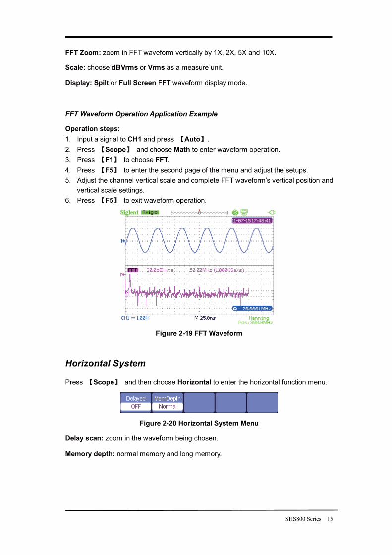
FFT Waveform Operation Application Example
Operation steps: 1. Input a signal to CH1 and press Auto . 2. Press Scope and choose Math to enter waveform operation. 3. Press F1 to choose FFT. 4. Press F5 to enter the second page of the menu and adjust the setups. 5. Adjust the channel vertical scale and complete FFT waveform’s vertical position and
vertical scale settings. 6. Press F5 to exit waveform operation.
Figure 2-19 FFT Waveform
Horizontal System
Press Scope and then choose Horizontal to enter the horizontal function menu.
Figure 2-20 Horizontal System Menu
Delay scan: zoom in the waveform being chosen.
Memory depth: normal memory and long memory.
16 SHS800 Series
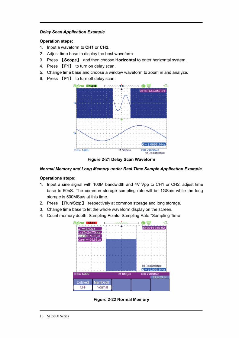
Delay Scan Application Example
Operation steps: 1. Input a waveform to CH1 or CH2. 2. Adjust time base to display the best waveform. 3. Press Scope and then choose Horizontal to enter horizontal system. 4. Press F1 to turn on delay scan. 5. Change time base and choose a window waveform to zoom in and analyze. 6. Press F1 to turn off delay scan.
Figure 2-21 Delay Scan Waveform
Normal Memory and Long Memory under Real Time Sample Application Example
Operations steps: 1. Input a sine signal with 100M bandwidth and 4V Vpp to CH1 or CH2, adjust time
base to 50nS. The common storage sampling rate will be 1GSa/s while the long storage is 500MSa/s at this time.
2. Press Run/Stop respectively at common storage and long storage. 3. Change time base to let the whole waveform display on the screen. 4. Count memory depth. Sampling Points=Sampling Rate *Sampling Time
Figure 2-22 Normal Memory
SHS800 Series 17
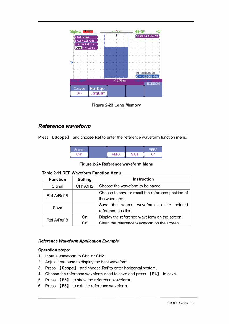
Figure 2-23 Long Memory
Reference waveform
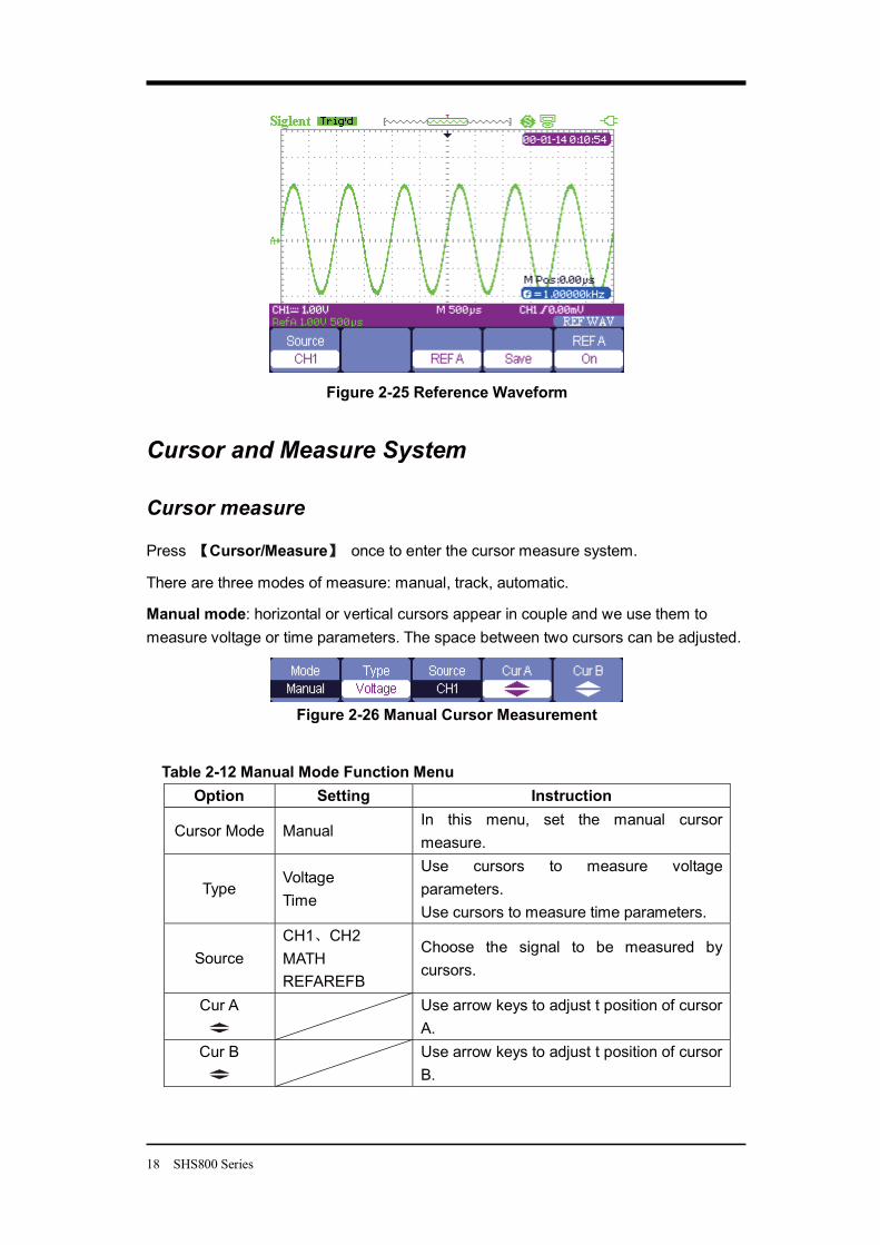
Press Scope and choose Ref to enter the reference waveform function menu.
Figure 2-24 Reference waveform Menu
Table 2-11 REF Waveform Function Menu Function Setting Instruction
Signal CH1/CH2 Choose the waveform to be saved.
Ref A/Ref B Choose to save or recall the reference position of the waveform..
Save Save the source waveform to the pointed reference position.
Ref A/Ref B On Off
Display the reference waveform on the screen. Clean the reference waveform on the screen.
Reference Waveform Application Example
Operation steps: 1. Input a waveform to CH1 or CH2. 2. Adjust time base to display the best waveform. 3. Press Scope and choose Ref to enter horizontal system. 4. Choose the reference waveform need to save and press F4 to save. 5. Press F5 to show the reference waveform. 6. Press F5 to exit the reference waveform.
18 SHS800 Series
Figure 2-25 Reference Waveform
Cursor and Measure System
Cursor measure
Press Cursor/Measure once to enter the cursor measure system.
There are three modes of measure: manual, track, automatic.
Manual mode: horizontal or vertical cursors appear in couple and we use them to measure voltage or time parameters. The space between two cursors can be adjusted.
Figure 2-26 Manual Cursor Measurement
Table 2-12 Manual Mode Function Menu Option Setting Instruction
Cursor Mode Manual In this menu, set the manual cursor measure.
Type Voltage Time
Use cursors to measure voltage parameters. Use cursors to measure time parameters.
Source CH1 CH2 MATH REFAREFB
Choose the signal to be measured by cursors.
Cur A
Use arrow keys to adjust t position of cursor A.
Cur B
Use arrow keys to adjust t position of cursor B.
SHS800 Series 19
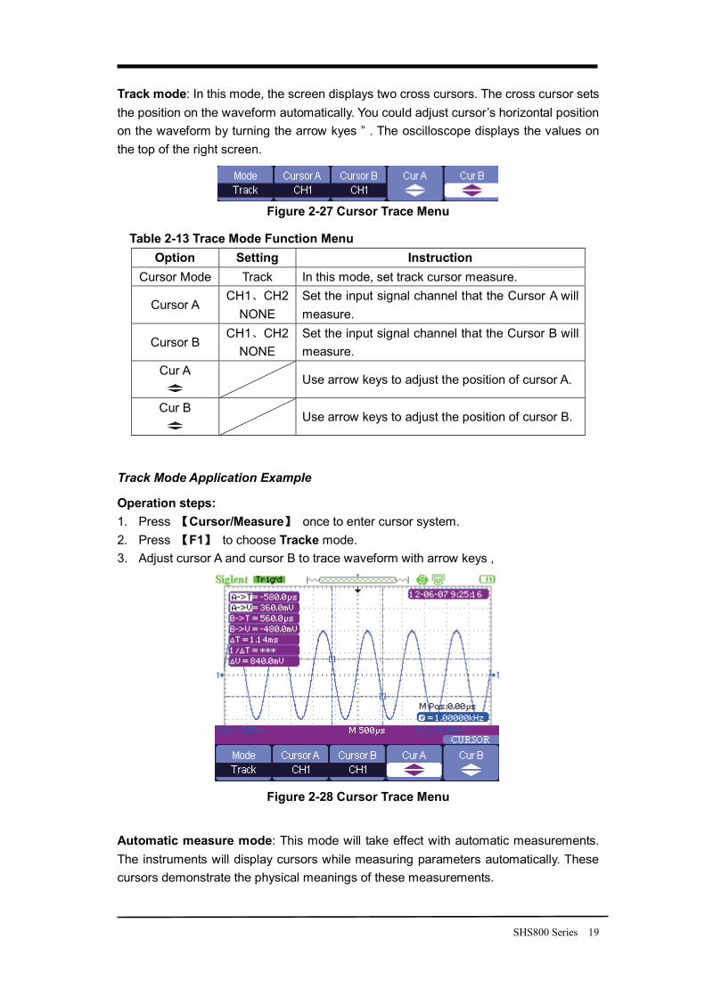
Track mode: In this mode, the screen displays two cross cursors. The cross cursor sets the position on the waveform automatically. You could adjust cursor’s horizontal position on the waveform by turning the arrow kyes ” . The oscilloscope displays the values on the top of the right screen.
Figure 2-27 Cursor Trace Menu
Table 2-13 Trace Mode Function Menu Option Setting Instruction
Cursor Mode Track In this mode, set track cursor measure.
Cursor A CH1 CH2
NONE Set the input signal channel that the Cursor A will measure.
Cursor B CH1 CH2
NONE Set the input signal channel that the Cursor B will measure.
Cur A
Use arrow keys to adjust the position of cursor A.
Cur B
Use arrow keys to adjust the position of cursor B.
Track Mode Application Example
Operation steps: 1. Press Cursor/Measure once to enter cursor system. 2. Press F1 to choose Tracke mode. 3. Adjust cursor A and cursor B to trace waveform with arrow keys ,
Figure 2-28 Cursor Trace Menu
Automatic measure mode: This mode will take effect with automatic measurements. The instruments will display cursors while measuring parameters automatically. These cursors demonstrate the physical meanings of these measurements.
20 SHS800 Series
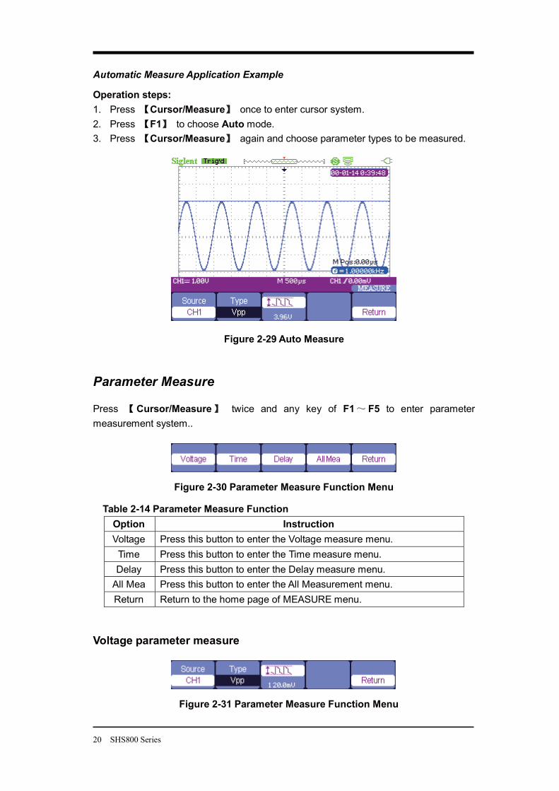
Automatic Measure Application Example
Operation steps: 1. Press Cursor/Measure once to enter cursor system. 2. Press F1 to choose Auto mode. 3. Press Cursor/Measure again and choose parameter types to be measured.
Figure 2-29 Auto Measure
Parameter Measure
Press Cursor/Measure twice and any key of F1 F5 to enter parameter measurement system..
Figure 2-30 Parameter Measure Function Menu
Table 2-14 Parameter Measure Function Option Instruction Voltage Press this button to enter the Voltage measure menu.
Time Press this button to enter the Time measure menu. Delay Press this button to enter the Delay measure menu.
All Mea Press this button to enter the All Measurement menu. Return Return to the home page of MEASURE menu.
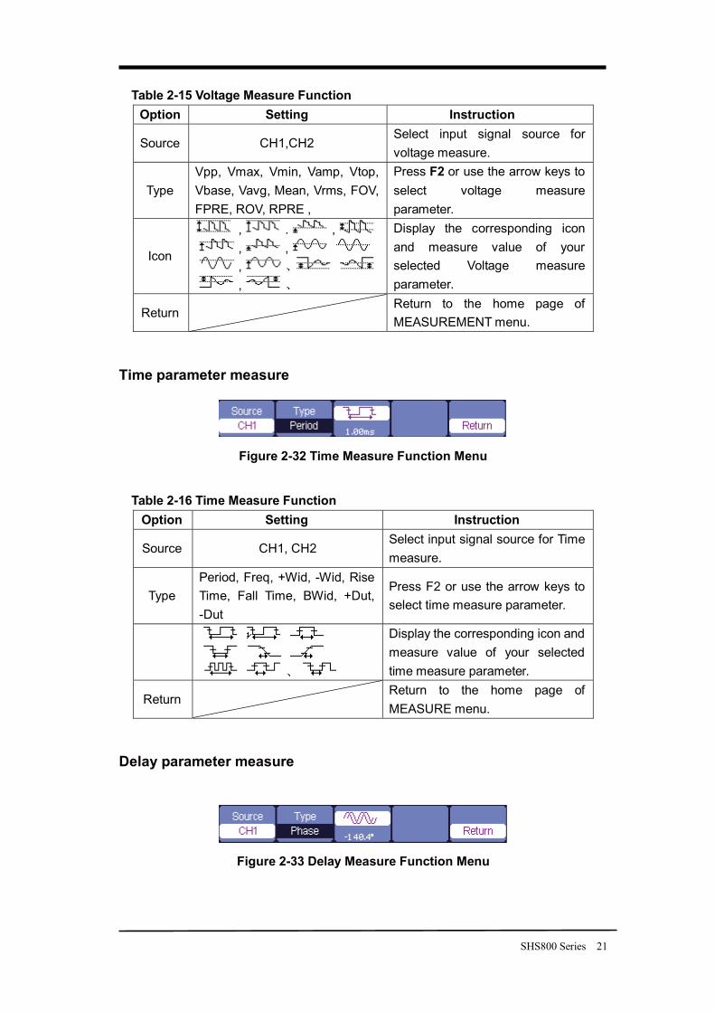
Voltage parameter measure
Figure 2-31 Parameter Measure Function Menu
SHS800 Series 21
Table 2-15 Voltage Measure Function Option Setting Instruction
Source CH1,CH2 Select input signal source for voltage measure.
Type Vpp, Vmax, Vmin, Vamp, Vtop, Vbase, Vavg, Mean, Vrms, FOV, FPRE, ROV, RPRE ,
Press F2 or use the arrow keys to select voltage measure parameter.
Icon
, . , , , , ,
Display the corresponding icon and measure value of your selected Voltage measure parameter.
Return Return to the home page of MEASUREMENT menu.
Time parameter measure
Figure 2-32 Time Measure Function Menu
Table 2-16 Time Measure Function Option Setting Instruction
Source CH1, CH2 Select input signal source for Time measure.
Type Period, Freq, +Wid, -Wid, Rise Time, Fall Time, BWid, +Dut, -Dut
Press F2 or use the arrow keys to select time measure parameter.
Display the corresponding icon and measure value of your selected time measure parameter.
Return Return to the home page of MEASURE menu.
Delay parameter measure
Figure 2-33 Delay Measure Function Menu
22 SHS800 Series
Table 2-17 Delay Measure Function Option Setting Instruction
Source CH1, CH2 Select input signal source for delay measure.
Type Phase FRR FRF FFR FFF
LRR LRF LFR LFF
Press the “Type” button or use arrow keys to select delay measure parameter.
Display the corresponding icon and measure value of your selected Delay measure parameter.
Return Return to the home page of MEASURE menu.
All parameters measure
Figure 2-34 All Measure Function Menu
Table 2-18 All Measure Function Menu Option Setting Instruction
Source CH1CH2
Select input signal channel.
Voltage
On/Off Turn on/off the all voltage parameters measure function.
Time On/Off Turn on/off the all time parameters measure function.
Delay On/Off Turn on/off the all delay parameters measurement function.
Return Return to the “All Measure main menu”.
Table 2-19 All Measure Function Menu Measure Type Introduction
Vmax The positive peak voltage. Vmin The negative peak voltage.
Vpp The absolute difference between positive peak voltage and negative peak voltage.
Vtop The maximal voltage during the measure. Vbase The minimal voltage during the measure. Vamp The difference between the Vtop and the Vbase voltage. Vavg The arithmetic mean over the first cycle of the waveform.
SHS800 Series 23
Mean The arithmetic mean over the entire waveform.
Crms Virtual value: the true Root Mean Square voltage of the first cycle in the waveform.
Vrms The true Root Mean Square voltage over the entire waveform.
ROVShoot Defined as (Vmax-Vhig)/Vamp after the waveform rising.
FOVShoot Defined as (Vmin-Vlow)/Vamp after the waveform falling.
RPREshoot Defined as (Vmin-Vlow)/Vamp before waveform rising.
FPREshoot Defined as (Vmax-Vhig)/Vamp before waveform falling.
Rise Time The time between the first voltage level rising from 10% to 90%.
Fall Time The time between the first voltage level falling from 90% to 10%
BWid The duration of a burst over the entire waveform.
+ Wid The time between the first rising edge and the next falling edge of 50% voltage level.
- Wid The time between the first falling edge and the next rising edge of 50% voltage level.
+ Duty The ratio between the first positive pulse width and the period.
- Duty The ratio between the first negative pulse width and the period.
Phase The phase difference between two waveforms.
FRR The time between the first rising edge of source 1 and the first rising edge of source 2.
FRF The time between the first rising edge of source 1 and the first falling edge of source 2.
FFR The time between the first falling edge of source 1 and the first rising edge of source 2.
FFF The time between the first falling edge of source 1 and the first falling edge of source 2.
LRR The time between the first rising edge of source 1 and the last rising edge of source 2.
LRF The time between the first rising edge of source 1 and the last falling edge of source 2.
LFR The time between the first falling edge of source 1 and the last rising edge of source 2.
LFF The time between the first falling edge of source 1 and the last falling edge of source 2.
24 SHS800 Series
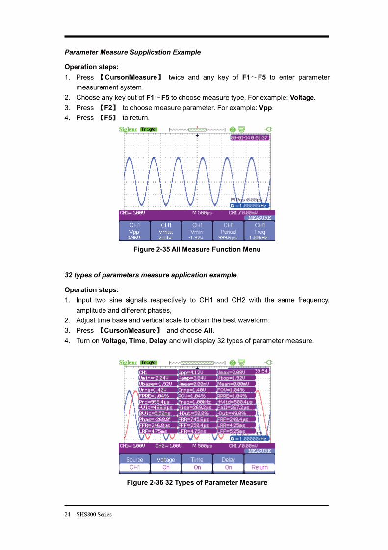
Parameter Measure Supplication Example
Operation steps: 1. Press Cursor/Measure twice and any key of F1 F5 to enter parameter
measurement system. 2. Choose any key out of F1 F5 to choose measure type. For example: Voltage. 3. Press F2 to choose measure parameter. For example: Vpp. 4. Press F5 to return.
Figure 2-35 All Measure Function Menu
32 types of parameters measure application example
Operation steps: 1. Input two sine signals respectively to CH1 and CH2 with the same frequency,
amplitude and different phases, 2. Adjust time base and vertical scale to obtain the best waveform. 3. Press Cursor/Measure and choose All. 4. Turn on Voltage, Time, Delay and will display 32 types of parameter measure.
Figure 2-36 32 Types of Parameter Measure
SHS800 Series 25
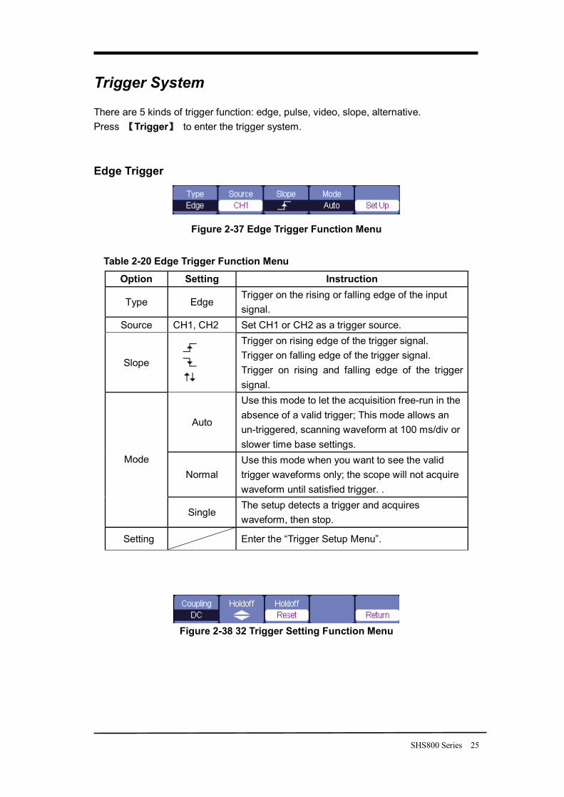
Trigger System
There are 5 kinds of trigger function: edge, pulse, video, slope, alternative. Press Trigger to enter the trigger system. Edge Trigger
Figure 2-37 Edge Trigger Function Menu
Table 2-20 Edge Trigger Function Menu
Option Setting Instruction
Type Edge Trigger on the rising or falling edge of the input signal.
Source CH1, CH2 Set CH1 or CH2 as a trigger source.
Slope
Trigger on rising edge of the trigger signal. Trigger on falling edge of the trigger signal. Trigger on rising and falling edge of the trigger signal.
Auto
Use this mode to let the acquisition free-run in the absence of a valid trigger; This mode allows an un-triggered, scanning waveform at 100 ms/div or slower time base settings.
Normal Use this mode when you want to see the valid trigger waveforms only; the scope will not acquire waveform until satisfied trigger. .
Mode
Single The setup detects a trigger and acquires waveform, then stop.
Setting Enter the “Trigger Setup Menu”.
Figure 2-38 32 Trigger Setting Function Menu
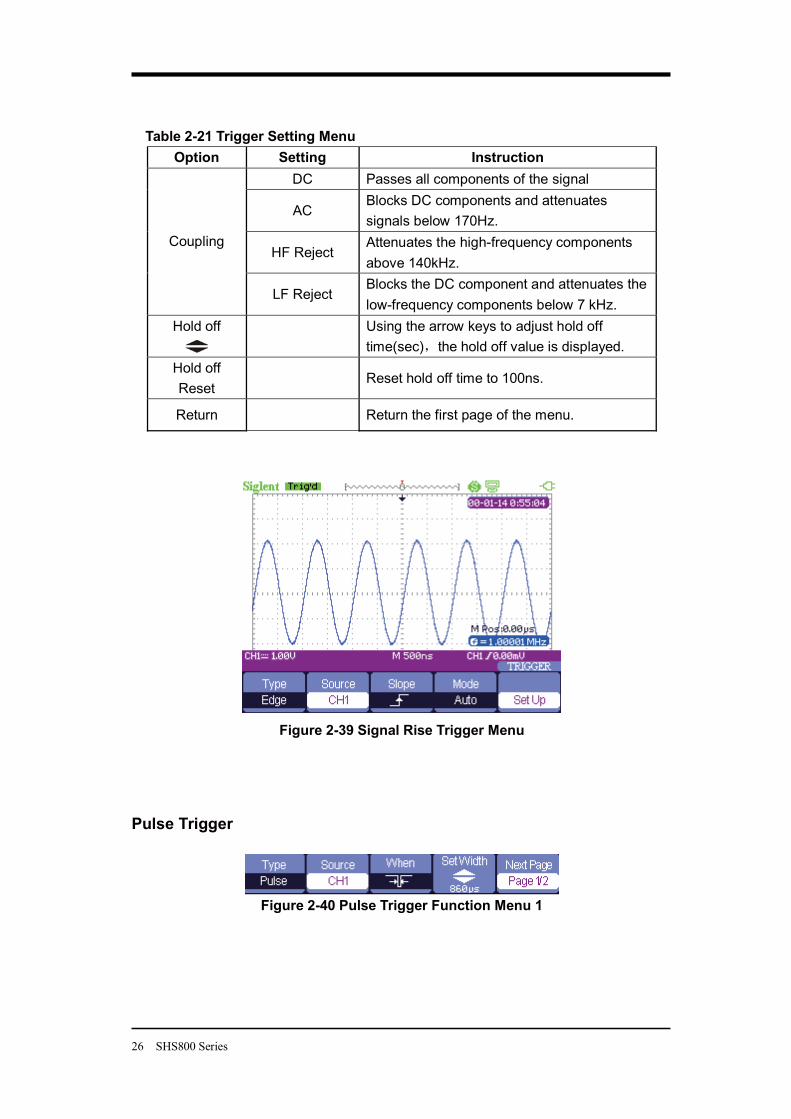
26 SHS800 Series
Table 2-21 Trigger Setting Menu Option Setting Instruction
DC Passes all components of the signal
AC Blocks DC components and attenuates signals below 170Hz.
HF Reject Attenuates the high-frequency components above 140kHz.
Coupling
LF Reject Blocks the DC component and attenuates the low-frequency components below 7 kHz.
Hold off
Using the arrow keys to adjust hold off time(sec) the hold off value is displayed.
Hold off Reset
Reset hold off time to 100ns.
Return Return the first page of the menu.
Figure 2-39 Signal Rise Trigger Menu
Pulse Trigger
Figure 2-40 Pulse Trigger Function Menu 1
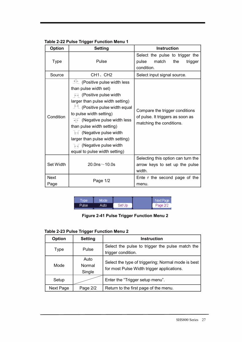
SHS800 Series 27
Table 2-22 Pulse Trigger Function Menu 1 Option Setting Instruction
Type Pulse Select the pulse to trigger the pulse match the trigger condition.
Source CH1 CH2 Select input signal source.
Condition
(Positive pulse width less than pulse width set)
(Positive pulse width larger than pulse width setting)
(Positive pulse width equal to pulse width setting)
(Negative pulse width less than pulse width setting)
(Negative pulse width larger than pulse width setting)
(Negative pulse width equal to pulse width setting)
Compare the trigger conditions of pulse. It triggers as soon as matching the conditions.
Set Width 20.0ns 10.0s Selecting this option can turn the arrow keys to set up the pulse width.
Next Page
Page 1/2 Ente r the second page of the menu.
Figure 2-41 Pulse Trigger Function Menu 2
Table 2-23 Pulse Trigger Function Menu 2 Option Setting Instruction
Type Pulse Select the pulse to trigger the pulse match the trigger condition.
Mode Auto
Normal Single
Select the type of triggering; Normal mode is best for most Pulse Width trigger applications.
Setup Enter the “Trigger setup menu”.
Next Page Page 2/2 Return to the first page of the menu.
28 SHS800 Series
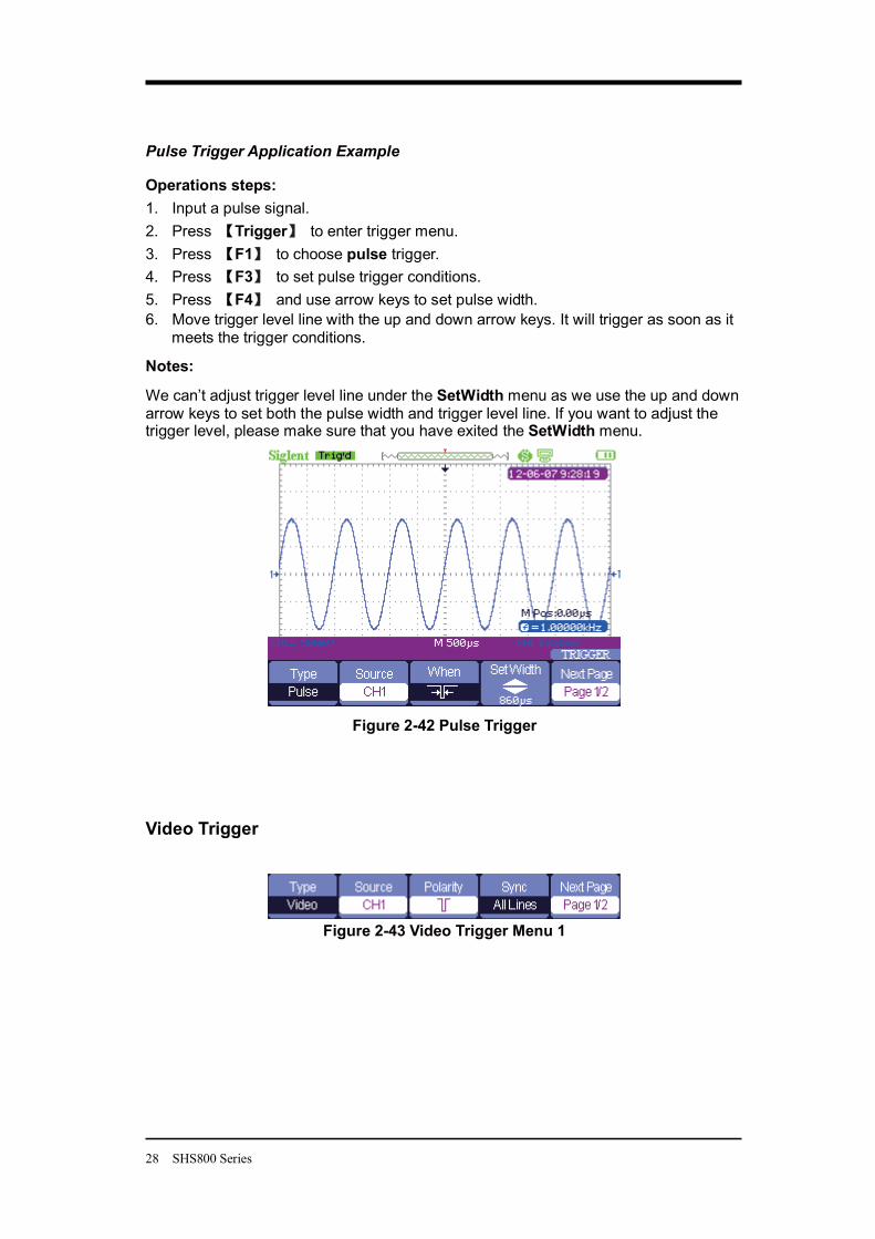
Pulse Trigger Application Example
Operations steps: 1. Input a pulse signal. 2. Press Trigger to enter trigger menu. 3. Press F1 to choose pulse trigger. 4. Press F3 to set pulse trigger conditions. 5. Press F4 and use arrow keys to set pulse width. 6. Move trigger level line with the up and down arrow keys. It will trigger as soon as it
meets the trigger conditions.
Notes:
We can’t adjust trigger level line under the SetWidth menu as we use the up and down arrow keys to set both the pulse width and trigger level line. If you want to adjust the trigger level, please make sure that you have exited the SetWidth menu.
Figure 2-42 Pulse Trigger
Video Trigger
Figure 2-43 Video Trigger Menu 1
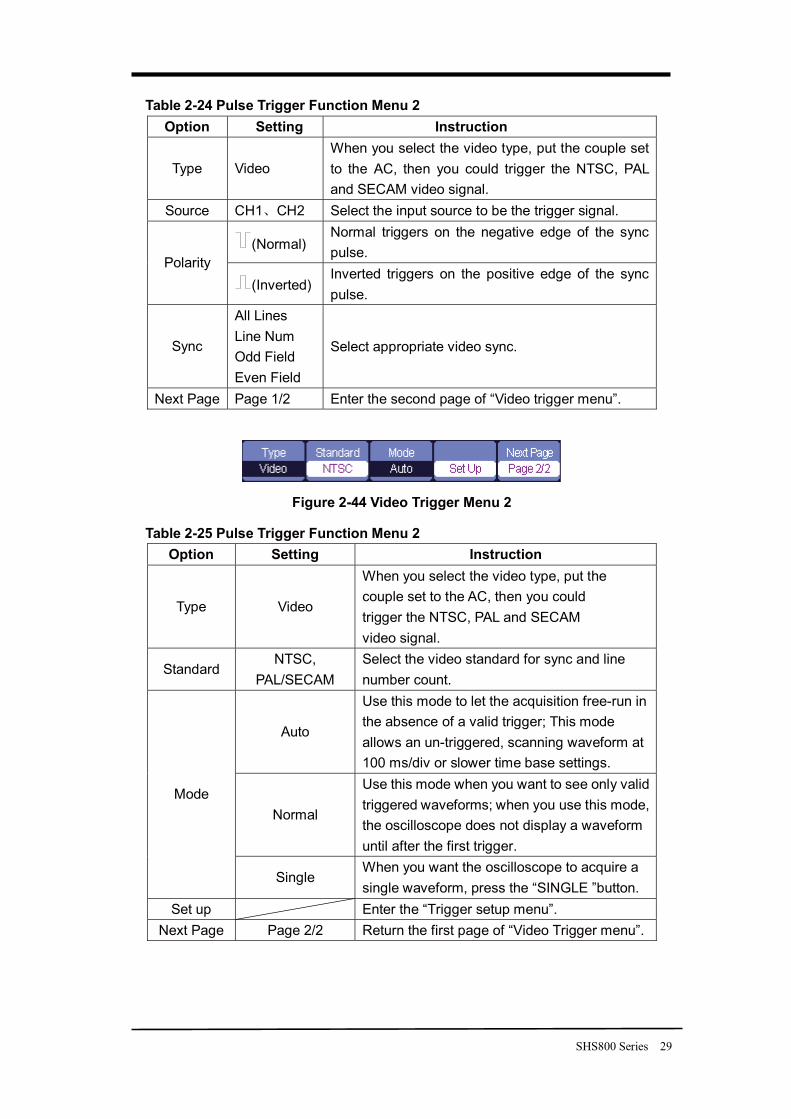
SHS800 Series 29
Table 2-24 Pulse Trigger Function Menu 2 Option Setting Instruction
Type Video When you select the video type, put the couple set to the AC, then you could trigger the NTSC, PAL and SECAM video signal.
Source CH1 CH2 Select the input source to be the trigger signal.
(Normal) Normal triggers on the negative edge of the sync pulse.
Polarity (Inverted)
Inverted triggers on the positive edge of the sync pulse.
Sync
All Lines Line Num Odd Field Even Field
Select appropriate video sync.
Next Page Page 1/2 Enter the second page of “Video trigger menu”.
Figure 2-44 Video Trigger Menu 2
Table 2-25 Pulse Trigger Function Menu 2 Option Setting Instruction
Type Video
When you select the video type, put the couple set to the AC, then you could trigger the NTSC, PAL and SECAM video signal.
Standard NTSC,
PAL/SECAM Select the video standard for sync and line number count.
Auto
Use this mode to let the acquisition free-run in the absence of a valid trigger; This mode allows an un-triggered, scanning waveform at 100 ms/div or slower time base settings.
Normal
Use this mode when you want to see only valid triggered waveforms; when you use this mode, the oscilloscope does not display a waveform until after the first trigger.
Mode
Single When you want the oscilloscope to acquire a single waveform, press the “SINGLE ”button.
Set up Enter the “Trigger setup menu”. Next Page Page 2/2 Return the first page of “Video Trigger menu”.
30 SHS800 Series
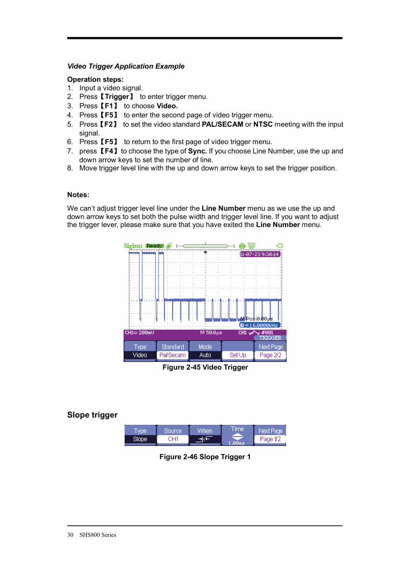
Video Trigger Application Example
Operation steps: 1. Input a video signal. 2. Press Trigger to enter trigger menu. 3. Press F1 to choose Video. 4. Press F5 to enter the second page of video trigger menu. 5. Press F2 to set the video standard PAL/SECAM or NTSC meeting with the input
signal. 6. Press F5 to return to the first page of video trigger menu. 7. press F4 to choose the type of Sync. If you choose Line Number, use the up and
down arrow keys to set the number of line. 8. Move trigger level line with the up and down arrow keys to set the trigger position.
Notes:
We can’t adjust trigger level line under the Line Number menu as we use the up and down arrow keys to set both the pulse width and trigger level line. If you want to adjust the trigger lever, please make sure that you have exited the Line Number menu.
Figure 2-45 Video Trigger
Slope trigger
Figure 2-46 Slope Trigger 1
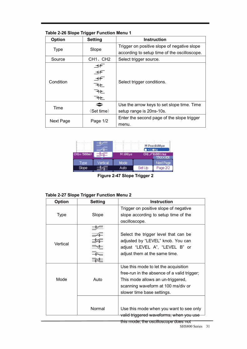
SHS800 Series 31
Table 2-26 Slope Trigger Function Menu 1 Option Setting Instruction
Type Slope Trigger on positive slope of negative slope according to setup time of the oscilloscope.
Source CH1 CH2 Select trigger source.
Condition
Select trigger conditions.
Time Set time
Use the arrow keys to set slope time. Time setup range is 20ns-10s.
Next Page Page 1/2 Enter the second page of the slope trigger menu.
Figure 2-47 Slope Trigger 2
Table 2-27 Slope Trigger Function Menu 2 Option Setting Instruction
Type Slope Trigger on positive slope of negative slope according to setup time of the oscilloscope.
Vertical
Select the trigger level that can be adjusted by “LEVEL” knob. You can adjust “LEVEL A”, “LEVEL B” or adjust them at the same time.
Auto
Use this mode to let the acquisition free-run in the absence of a valid trigger; This mode allows an un-triggered, scanning waveform at 100 ms/div or slower time base settings.
Mode
Normal Use this mode when you want to see only valid triggered waveforms; when you use this mode, the oscilloscope does not
32 SHS800 Series
display a waveform until after the first trigger.
Single When you want the oscilloscope to acquire a single waveform, press the “SINGLE ” button.
Set up Enter the “Trigger setup menu”. Next Page Page 2/2 Return to the first page of slope trigger.
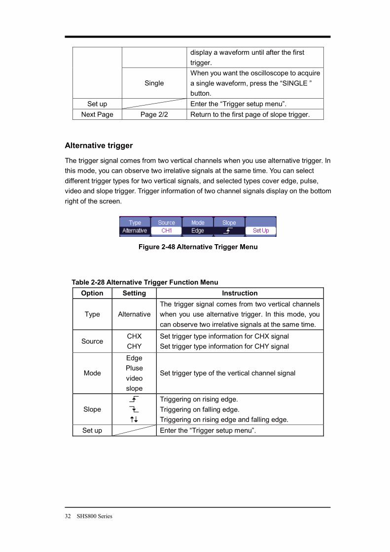
Alternative trigger
The trigger signal comes from two vertical channels when you use alternative trigger. In this mode, you can observe two irrelative signals at the same time. You can select different trigger types for two vertical signals, and selected types cover edge, pulse, video and slope trigger. Trigger information of two channel signals display on the bottom right of the screen.
Figure 2-48 Alternative Trigger Menu
Table 2-28 Alternative Trigger Function Menu Option Setting Instruction
Type Alternative The trigger signal comes from two vertical channels when you use alternative trigger. In this mode, you can observe two irrelative signals at the same time.
Source CHX CHY
Set trigger type information for CHX signal Set trigger type information for CHY signal
Mode
Edge Pluse video slope
Set trigger type of the vertical channel signal
Slope
Triggering on rising edge. Triggering on falling edge. Triggering on rising edge and falling edge.
Set up Enter the “Trigger setup menu”.
SHS800 Series 33
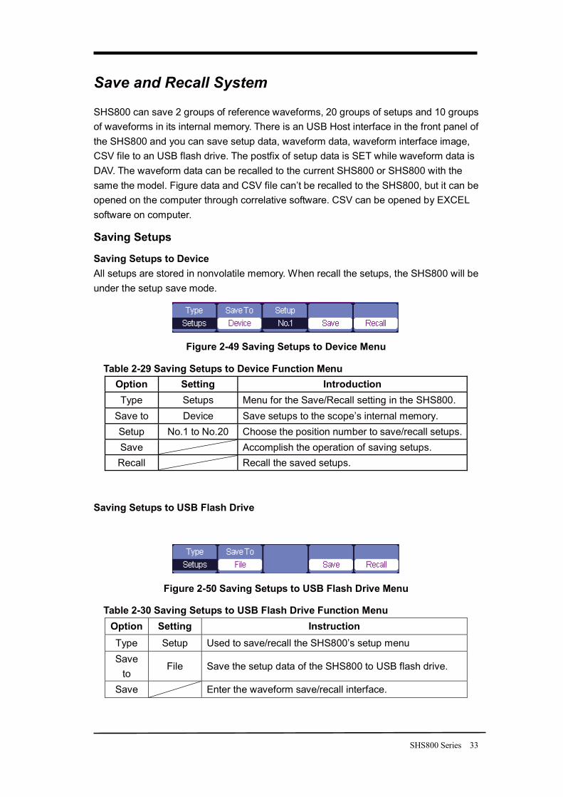
Save and Recall System
SHS800 can save 2 groups of reference waveforms, 20 groups of setups and 10 groups of waveforms in its internal memory. There is an USB Host interface in the front panel of the SHS800 and you can save setup data, waveform data, waveform interface image, CSV file to an USB flash drive. The postfix of setup data is SET while waveform data is DAV. The waveform data can be recalled to the current SHS800 or SHS800 with the same the model. Figure data and CSV file can’t be recalled to the SHS800, but it can be opened on the computer through correlative software. CSV can be opened by EXCEL software on computer.
Saving Setups
Saving Setups to Device All setups are stored in nonvolatile memory. When recall the setups, the SHS800 will be under the setup save mode.
Figure 2-49 Saving Setups to Device Menu
Table 2-29 Saving Setups to Device Function Menu Option Setting Introduction Type Setups Menu for the Save/Recall setting in the SHS800.
Save to Device Save setups to the scope’s internal memory. Setup No.1 to No.20 Choose the position number to save/recall setups. Save Accomplish the operation of saving setups. Recall Recall the saved setups.
Saving Setups to USB Flash Drive
Figure 2-50 Saving Setups to USB Flash Drive Menu
Table 2-30 Saving Setups to USB Flash Drive Function Menu Option Setting Instruction Type Setup Used to save/recall the SHS800’s setup menu Save
to File Save the setup data of the SHS800 to USB flash drive.
Save Enter the waveform save/recall interface.
34 SHS800 Series
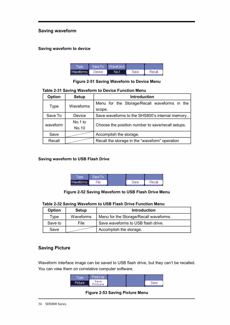
Saving waveform
Saving waveform to device
Figure 2-51 Saving Waveform to Device Menu
Table 2-31 Saving Waveform to Device Function Menu Option Setup Introduction
Type Waveforms Menu for the Storage/Recall waveforms in the scope.
Save To Device Save waveforms to the SHS800’s internal memory..
waveform No.1 to No.10
Choose the position number to save/recall setups.
Save Accomplish the storage. Recall Recall the storage in the “waveform” operation
Saving waveform to USB Flash Drive
Figure 2-52 Saving Waveform to USB Flash Drive Menu Table 2-32 Saving Waveform to USB Flash Drive Function Menu
Option Setup Introduction Type Waveforms Menu for the Storage/Recall waveforms.
Save to File Save waveforms to USB flash drive. Save Accomplish the storage.
Saving Picture
Waveform interface image can be saved to USB flash drive, but they can’t be recalled. You can view them on correlative computer software.
Figure 2-53 Saving Picture Menu
SHS800 Series 35
Table 2-33 Saving Picture Function Menu
Option Setting Introduction
Type Picture Menu for the Storage/Recall waveform interface image.
Print Key
Print Picture
Save Picture
Choose Print Picture option and press Save/Recall for 4 seconds to print the picture while the SHS800 connects to the printer. Choose Save Picture option and press Save/Recall for 4 seconds to save the picture while you insert an USB flash driver to the SHS800.
Save Go to the Save/Recall interface.
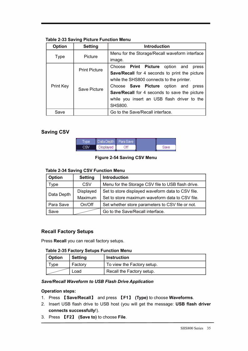
Saving CSV
Figure 2-54 Saving CSV Menu
Table 2-34 Saving CSV Function Menu Option Setting Introduction Type CSV Menu for the Storage CSV file to USB flash drive.
Data Depth Displayed Maximum
Set to store displayed waveform data to CSV file. Set to store maximum waveform data to CSV file.
Para Save On/Off Set whether store parameters to CSV file or not. Save Go to the Save/Recall interface.
Recall Factory Setups
Press Recall you can recall factory setups.
Table 2-35 Factory Setups Function Menu Option Setting Instruction Type Factory To view the Factory setup.
Load Recall the Factory setup.
Save/Recall Waveform to USB Flash Drive Application
Operation steps: 1. Press Save/Recall and press F1 (Type) to choose Waveforms. 2. Insert USB flash drive to USB host (you will get the message: USB flash driver
connects successfully!). 3. Press F2 (Save to) to choose File.
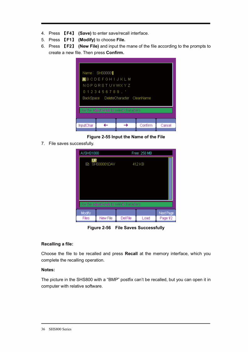
36 SHS800 Series
4. Press F4 (Save) to enter save/recall interface. 5. Press F1 (Modify) to choose File. 6. Press F2 (New File) and input the mane of the file according to the prompts to
create a new file. Then press Confirm.
Figure 2-55 Input the Name of the File
7. File saves successfully.
Figure 2-56 File Saves Successfully
Recalling a file:
Choose the file to be recalled and press Recall at the memory interface, which you complete the recalling operation.
Notes:
The picture in the SHS800 with a “BMP” postfix can’t be recalled, but you can open it in computer with relative software.
SHS800 Series 37
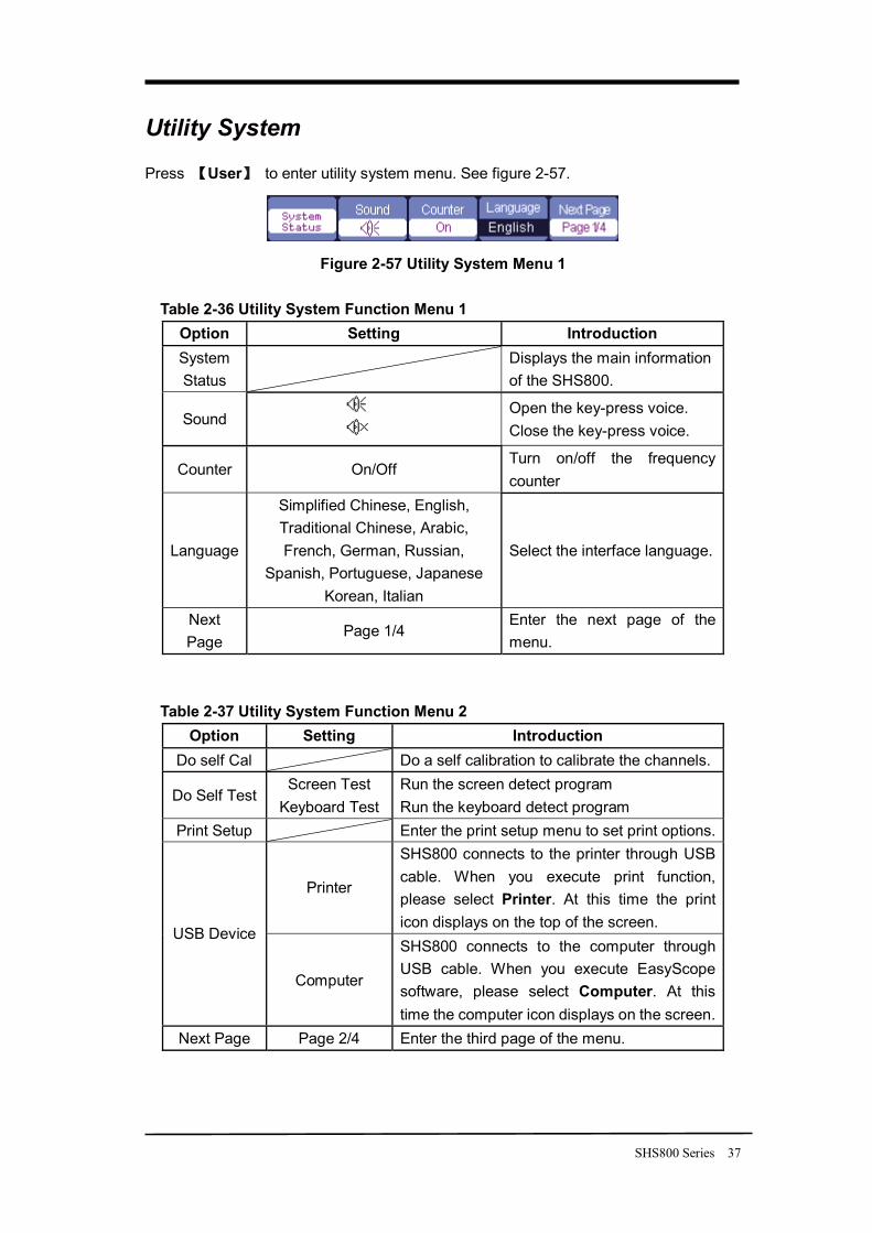
Utility System
Press User to enter utility system menu. See figure 2-57.
Figure 2-57 Utility System Menu 1
Table 2-36 Utility System Function Menu 1 Option Setting Introduction System Status
Displays the main information of the SHS800.
Sound Open the key-press voice.
Close the key-press voice.
Counter On/Off Turn on/off the frequency counter
Language
Simplified Chinese, English, Traditional Chinese, Arabic, French, German, Russian,
Spanish, Portuguese, Japanese Korean, Italian
Select the interface language.
Next Page
Page 1/4 Enter the next page of the menu.
Table 2-37 Utility System Function Menu 2 Option Setting Introduction
Do self Cal Do a self calibration to calibrate the channels.
Do Self Test Screen Test
Keyboard Test Run the screen detect program Run the keyboard detect program
Print Setup Enter the print setup menu to set print options.
Printer
SHS800 connects to the printer through USB cable. When you execute print function, please select Printer. At this time the print icon displays on the top of the screen.
USB Device
Computer
SHS800 connects to the computer through USB cable. When you execute EasyScope software, please select Computer. At this time the computer icon displays on the screen.
Next Page Page 2/4 Enter the third page of the menu.
38 SHS800 Series
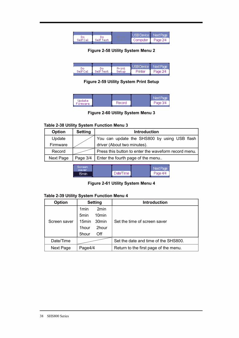
Figure 2-58 Utility System Menu 2
Figure 2-59 Utility System Print Setup
Figure 2-60 Utility System Menu 3 Table 2-38 Utility System Function Menu 3
Option Setting Introduction Update
Firmware
You can update the SHS800 by using USB flash driver (About two minutes).
Record Press this button to enter the waveform record menu. Next Page Page 3/4 Enter the fourth page of the menu..
Figure 2-61 Utility System Menu 4
Table 2-39 Utility System Function Menu 4 Option Setting Introduction
Screen saver
1min 2min 5min 10min 15min 30min 1hour 2hour 5hour Off
Set the time of screen saver
Date/Time Set the date and time of the SHS800. Next Page Page4/4 Return to the first page of the menu.
SHS800 Series 39
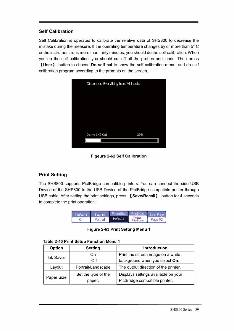
Self Calibration
Self Calibration is operated to calibrate the relative data of SHS800 to decrease the mistake during the measure. If the operating temperature changes by or more than 5° C or the instrument runs more than thirty minutes, you should do the self calibration. When you do the self calibration, you should cut off all the probes and leads. Then press
User button to choose Do self cal to show the self calibration menu, and do self calibration program according to the prompts on the screen.
Figeure 2-62 Self Calibration
Print Setting
The SHS800 supports PictBridge compatible printers. You can connect the side USB Device of the SHS800 to the USB Device of the PictBridge compatible printer through USB cable. After setting the print settings, press Save/Recall button for 4 seconds to complete the print operation.
Figure 2-63 Print Setting Menu 1
Table 2-40 Print Setup Function Menu 1 Option Setting Introduction
Ink Saver On Off
Print the screen image on a white background when you select On.
Layout Portrait/Landscape The output direction of the printer.
Paper Size Set the type of the
paper. Displays settings available on your PictBridge compatible printer.
40 SHS800 Series
Print Picture
Choose Print Picture option and press Save/Recall for 4 seconds to print the picture while the SHS800 connects to the printer.
Print Key
Save Picture
Choose Save Picture option and press Save/Recall for 4 seconds to save the picture while you insert an USB flash driver to the SHS800.
Next Page Page 1/2 Enter the second page of the menu.
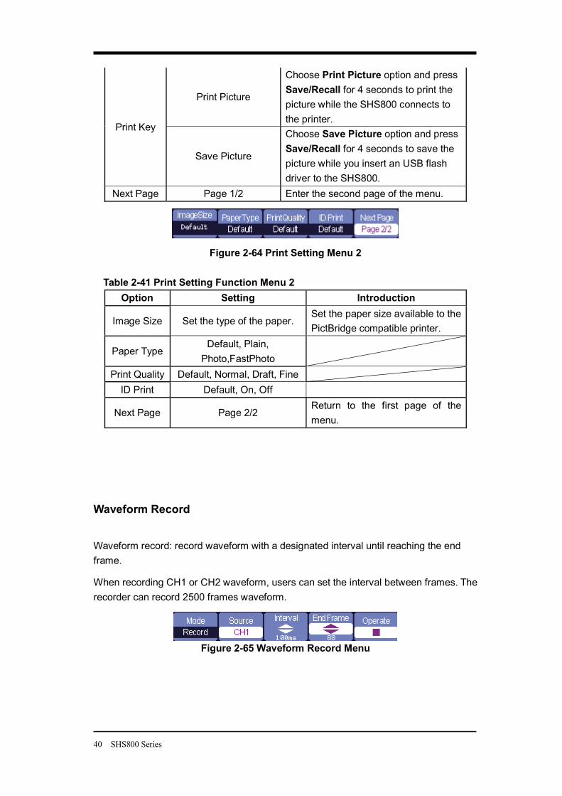
Figure 2-64 Print Setting Menu 2
Table 2-41 Print Setting Function Menu 2 Option Setting Introduction
Image Size Set the type of the paper. Set the paper size available to the PictBridge compatible printer.
Paper Type Default, Plain,
Photo,FastPhoto
Print Quality Default, Normal, Draft, Fine ID Print Default, On, Off
Next Page Page 2/2 Return to the first page of the menu.
Waveform Record
Waveform record: record waveform with a designated interval until reaching the end frame.
When recording CH1 or CH2 waveform, users can set the interval between frames. The recorder can record 2500 frames waveform.
Figure 2-65 Waveform Record Menu
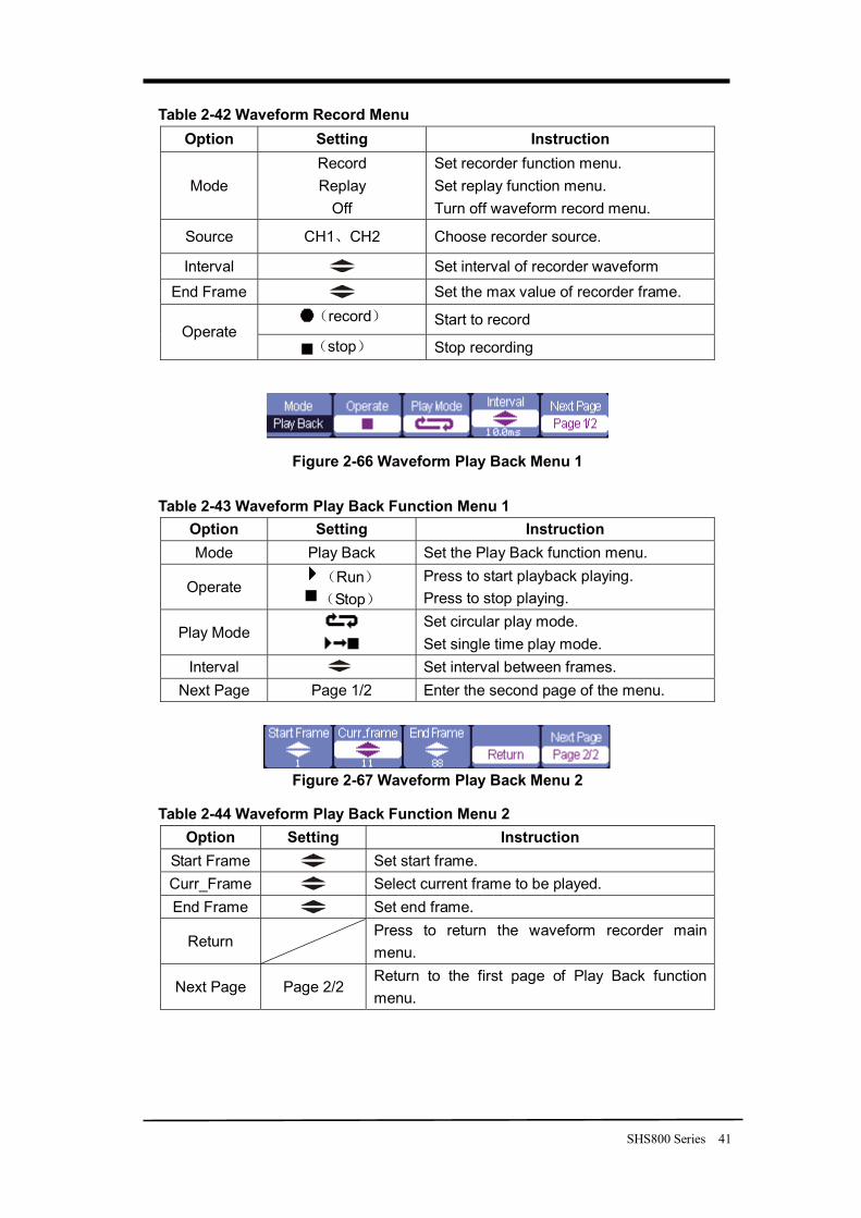
SHS800 Series 41
Table 2-42 Waveform Record Menu Option Setting Instruction
Mode Record Replay
Off
Set recorder function menu. Set replay function menu. Turn off waveform record menu.
Source CH1 CH2 Choose recorder source.
Interval Set interval of recorder waveform End Frame Set the max value of recorder frame.
record Start to record Operate
stop Stop recording
Figure 2-66 Waveform Play Back Menu 1
Table 2-43 Waveform Play Back Function Menu 1 Option Setting Instruction Mode Play Back Set the Play Back function menu.
Operate Run Stop
Press to start playback playing. Press to stop playing.
Play Mode
Set circular play mode. Set single time play mode.
Interval Set interval between frames. Next Page Page 1/2 Enter the second page of the menu.
Figure 2-67 Waveform Play Back Menu 2
Table 2-44 Waveform Play Back Function Menu 2 Option Setting Instruction
Start Frame Set start frame. Curr_Frame Select current frame to be played. End Frame Set end frame.
Return Press to return the waveform recorder main menu.
Next Page Page 2/2 Return to the first page of Play Back function menu.
42 SHS800 Series
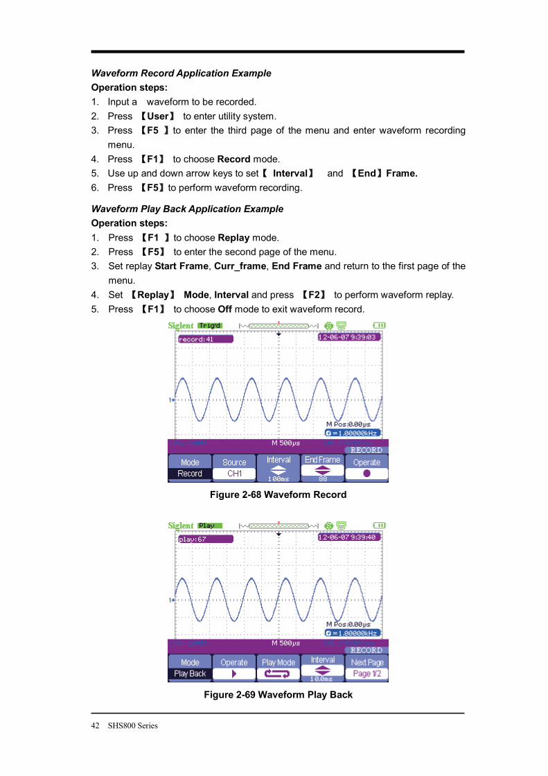
Waveform Record Application Example Operation steps: 1. Input a waveform to be recorded. 2. Press User to enter utility system. 3. Press F5 to enter the third page of the menu and enter waveform recording
menu. 4. Press F1 to choose Record mode. 5. Use up and down arrow keys to set Interval and End Frame. 6. Press F5 to perform waveform recording.
Waveform Play Back Application Example Operation steps: 1. Press F1 to choose Replay mode. 2. Press F5 to enter the second page of the menu. 3. Set replay Start Frame, Curr_frame, End Frame and return to the first page of the
menu. 4. Set Replay Mode, Interval and press F2 to perform waveform replay. 5. Press F1 to choose Off mode to exit waveform record.
Figure 2-68 Waveform Record
Figure 2-69 Waveform Play Back
SHS800 Series 43
Chapter 3 Using the Multimeter About this Chapter
This chapter provides a step-by-step introduction to the multimeter functions of SHS800 series Handheld Digital Oscilloscope. The introduction gives basic examples to show how to use the menus and perform basic operations.
The digital multimeter provides the following functions: making DC voltage, AC voltage, resistance, diode, continuity, capacitance, DC current, and AC current measurements.
Notes:
1. You should use the multimeter with correct connections as instructions. 2. The key Rub/Stop can hold the screen.
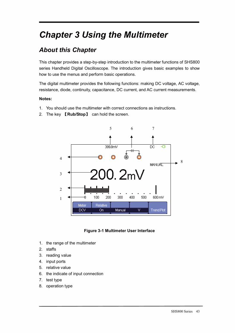
Figure 3-1 Multimeter User Interface
1. the range of the multimeter 2. staffs 3. reading value 4. input ports 5. relative value 6. the indicate of input connection 7. test type 8. operation type
1
2
3
4 8
5 6 7
44 SHS800 Series
Making DC and AC Voltage Measurement
Table 3-1 DC and AC Function Menu Option Setting Instruction
On Save the current input value as a reference and record again. Real value equals relative value plus measurement value
Relative Value
Off Real value equals measurement value
Auto Choose the best measurement scale automatically Mode
Manual Choose measurement scale manually
Auto Choose the best measurement scale automatically according to the measurement value. Scale
Manual Choose measurement scale manually and there will be a warring when over the scale.
Tendency Plot On Plot with the measurements according to time
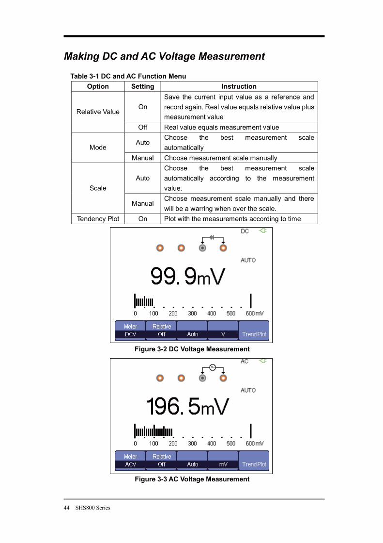
Figure 3-2 DC Voltage Measurement
Figure 3-3 AC Voltage Measurement
SHS800 Series 45
Operation Steps: 1. Press Meter to enter multimeter mode, press F1 to choose DCV, ACV
measurement. 2. Insert the red probe to the V.Ω.C banana jack input and the black probe to the
COM. Connect the other end of probes to the power or load to be measured. 3. Turn on /off the relative according to the real demand. 4. Choose Manual or Auto according to the real demand. 5. Read voltage value.
Making Resistance Measurement
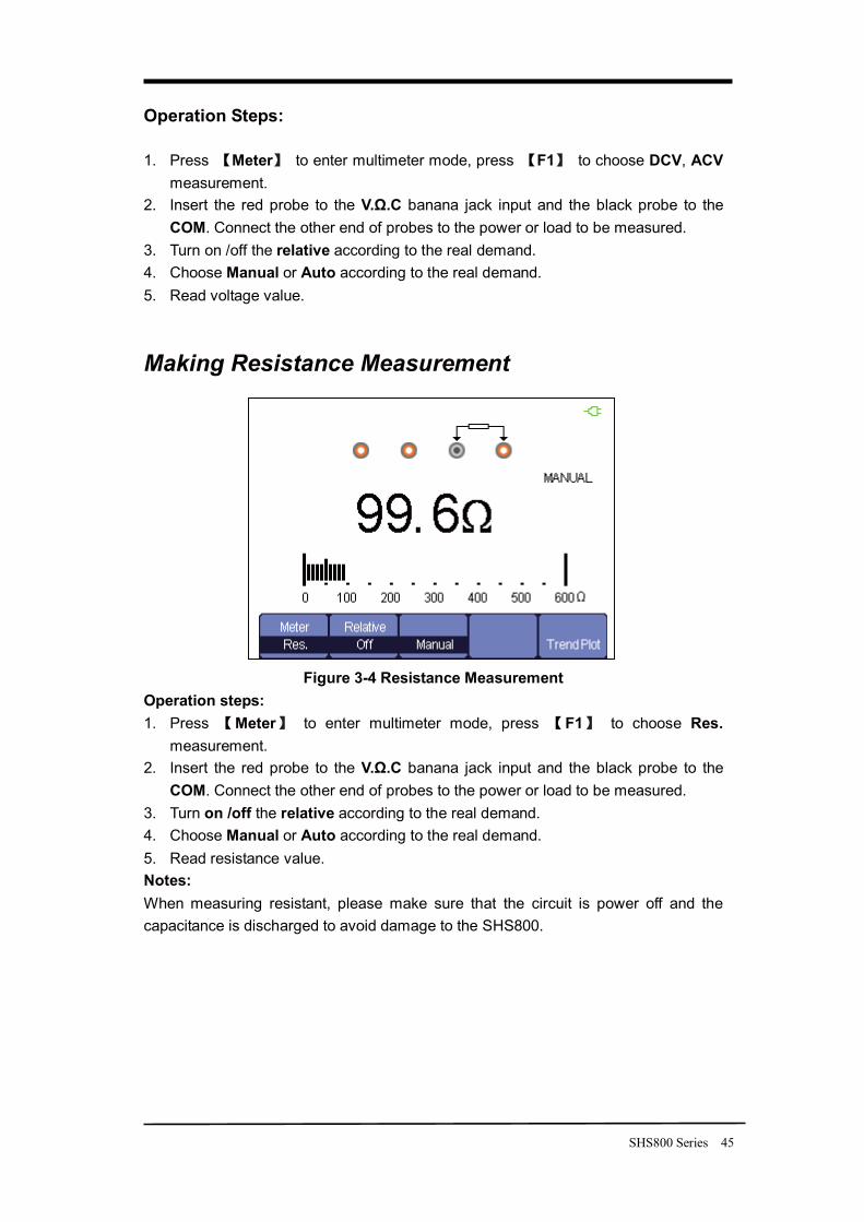
Figure 3-4 Resistance Measurement
Operation steps: 1. Press Meter to enter multimeter mode, press F1 to choose Res.
measurement. 2. Insert the red probe to the V.Ω.C banana jack input and the black probe to the
COM. Connect the other end of probes to the power or load to be measured. 3. Turn on /off the relative according to the real demand. 4. Choose Manual or Auto according to the real demand. 5. Read resistance value. Notes: When measuring resistant, please make sure that the circuit is power off and the capacitance is discharged to avoid damage to the SHS800.
46 SHS800 Series
Making Diode Measurement
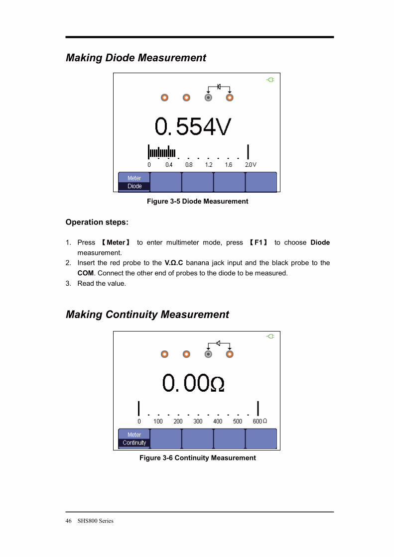
Figure 3-5 Diode Measurement
Operation steps: 1. Press Meter to enter multimeter mode, press F1 to choose Diode
measurement. 2. Insert the red probe to the V.Ω.C banana jack input and the black probe to the
COM. Connect the other end of probes to the diode to be measured. 3. Read the value.
Making Continuity Measurement
Figure 3-6 Continuity Measurement
SHS800 Series 47
Operation steps: 1. Press Meter to enter multimeter mode, press F1 to choose Continuity
measurement. 2. Insert the red probe to the V.Ω.C banana jack input and the black probe to the
COM. Connect the other end of probes to the object to be measured. 3. When the measured object is under 50 , the multimeter will alarm and read
value. 4. When the measured object is above 50 , the multimeter will not alarm and read
value.
Making Capacitance Measurement
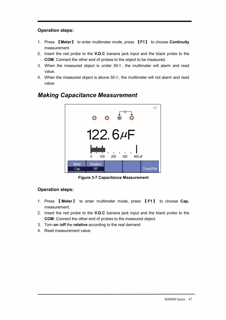
Figure 3-7 Capacitance Measurement
Operation steps: 1. Press Meter to enter multimeter mode, press F1 to choose Cap.
measurement. 2. Insert the red probe to the V.Ω.C banana jack input and the black probe to the
COM. Connect the other end of probes to the measured object. 3. Turn on /off the relative according to the real demand. 4. Read measurement value.
48 SHS800 Series
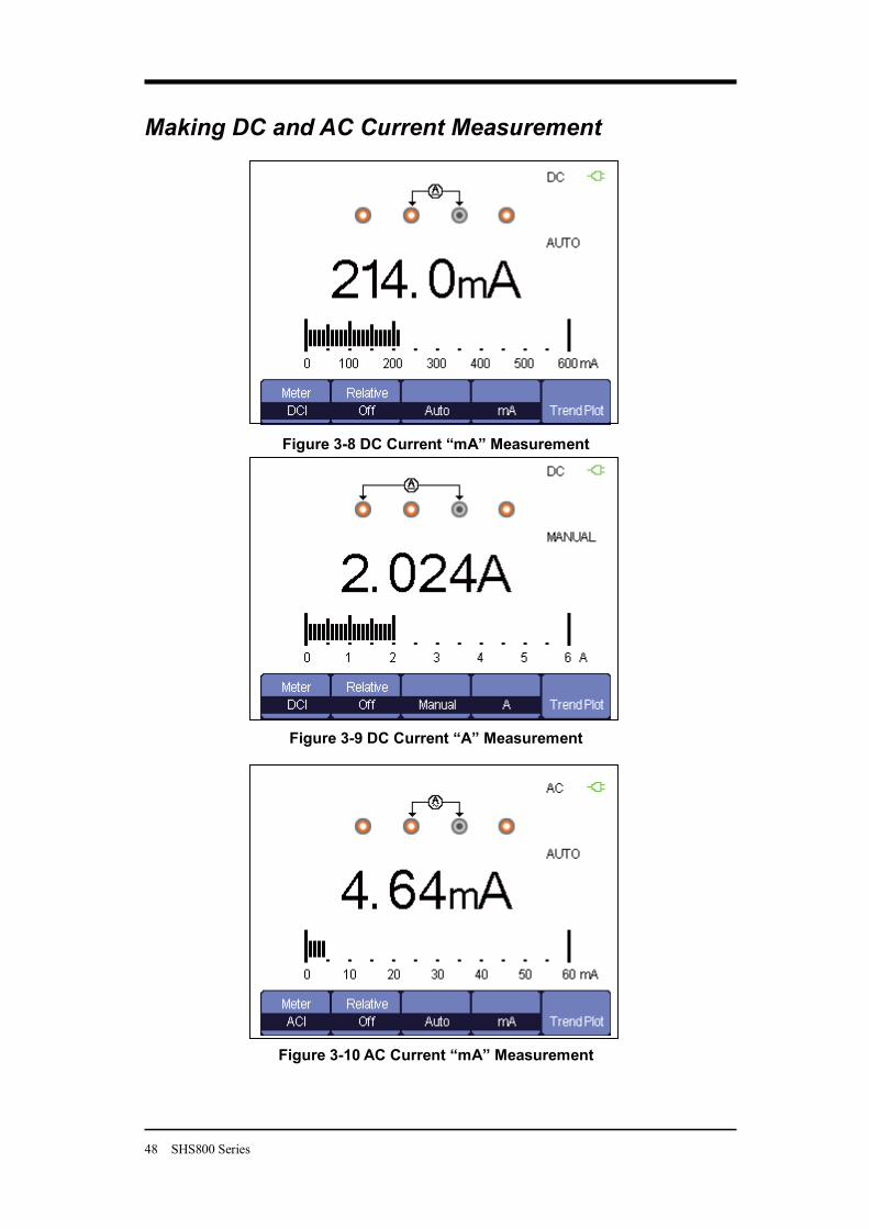
Making DC and AC Current Measurement
Figure 3-8 DC Current “mA” Measurement
Figure 3-9 DC Current “A” Measurement
Figure 3-10 AC Current “mA” Measurement
SHS800 Series 49
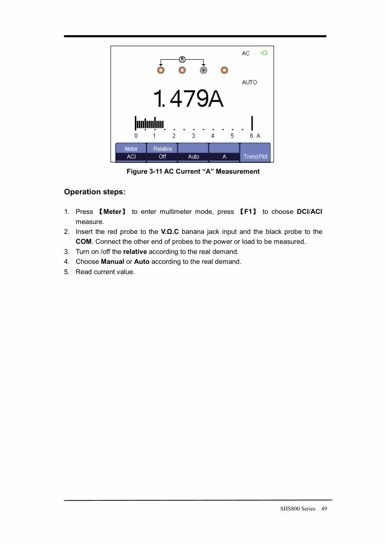
Figure 3-11 AC Current “A” Measurement
Operation steps: 1. Press Meter to enter multimeter mode, press F1 to choose DCI/ACI
measure. 2. Insert the red probe to the V.Ω.C banana jack input and the black probe to the
COM. Connect the other end of probes to the power or load to be measured. 3. Turn on /off the relative according to the real demand. 4. Choose Manual or Auto according to the real demand. 5. Read current value.
50 SHS800 Series
Chapter 4 Using the Recorder Functions About this Chapter
This chapter provides a step-by-step introduction to the recorder functions of SHS800 series Handheld Digital Oscilloscope. The introduction gives basic examples to show how to use the menus and perform basic operations.
The recorder mainly includes the following functions:
Trend Plot: Trend plot is to save the measurements in the memory and then plot a graph of Scope or Meter measurements as a function of time.
Waveform Recorder: Record real time waveform without gap or space. That is to say every time the SHS800 can save all captured waveform data and then replay them. The maximal recording length of waveform recorder is 7M data points.
SHS800 Series 51
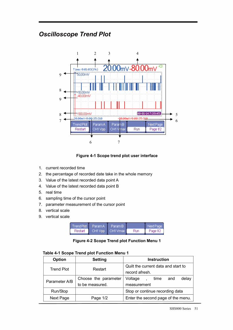
Oscilloscope Trend Plot
Figure 4-1 Scope trend plot user interface
1. current recorded time 2. the percentage of recorded date take in the whole memory 3. Value of the latest recorded data point A 4. Value of the latest recorded data point B 5. real time 6. sampling time of the cursor point 7. parameter measurement of the cursor point 8. vertical scale 9. vertical scale
Figure 4-2 Scope Trend plot Function Menu 1
Table 4-1 Scope Trend plot Function Menu 1 Option Setting Instruction
Trend Plot Restart Quilt the current data and start to record afresh.
Parameter A/B Choose the parameter to be measured.
Voltage , time and delay measurement
Run/Stop Stop or continue recording data Next Page Page 1/2 Enter the second page of the menu.
1 2 3 4
5 6
7 6
8 7
9
8
9
52 SHS800 Series
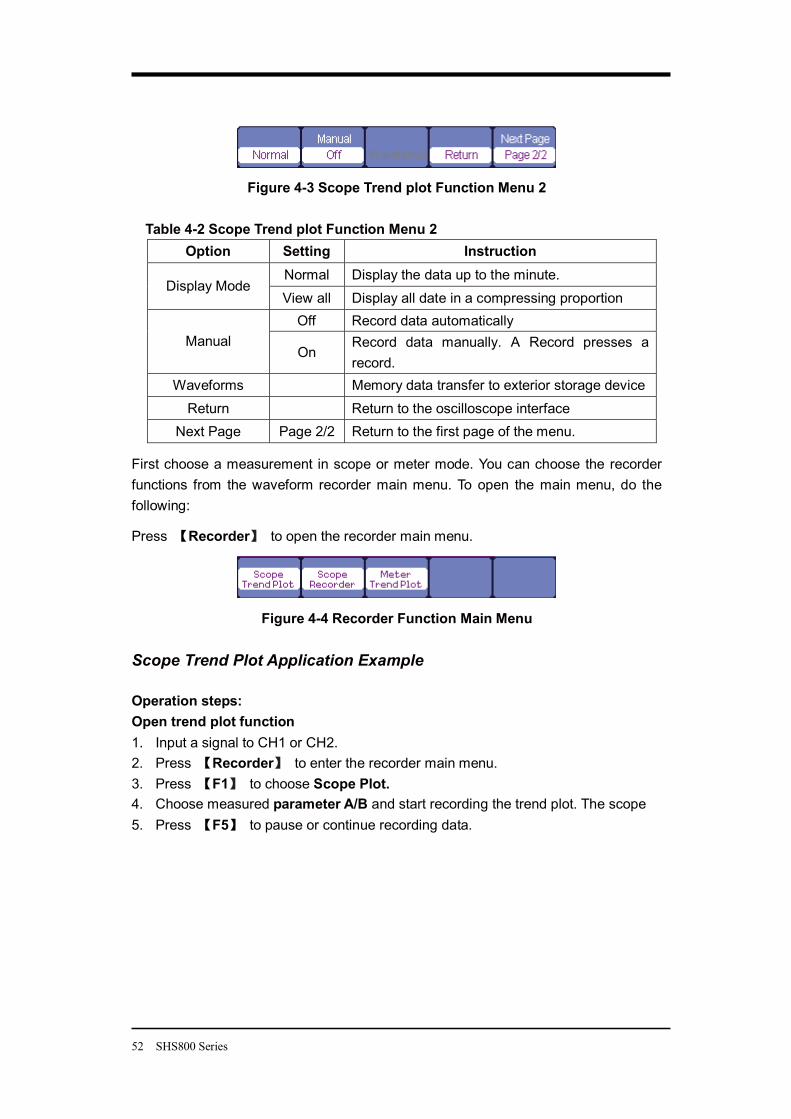
Figure 4-3 Scope Trend plot Function Menu 2
Table 4-2 Scope Trend plot Function Menu 2 Option Setting Instruction
Normal Display the data up to the minute. Display Mode
View all Display all date in a compressing proportion Off Record data automatically
Manual On
Record data manually. A Record presses a record.
Waveforms Memory data transfer to exterior storage device Return Return to the oscilloscope interface
Next Page Page 2/2 Return to the first page of the menu.
First choose a measurement in scope or meter mode. You can choose the recorder functions from the waveform recorder main menu. To open the main menu, do the following:
Press Recorder to open the recorder main menu.
Figure 4-4 Recorder Function Main Menu
Scope Trend Plot Application Example Operation steps: Open trend plot function 1. Input a signal to CH1 or CH2. 2. Press Recorder to enter the recorder main menu. 3. Press F1 to choose Scope Plot. 4. Choose measured parameter A/B and start recording the trend plot. The scope 5. Press F5 to pause or continue recording data.
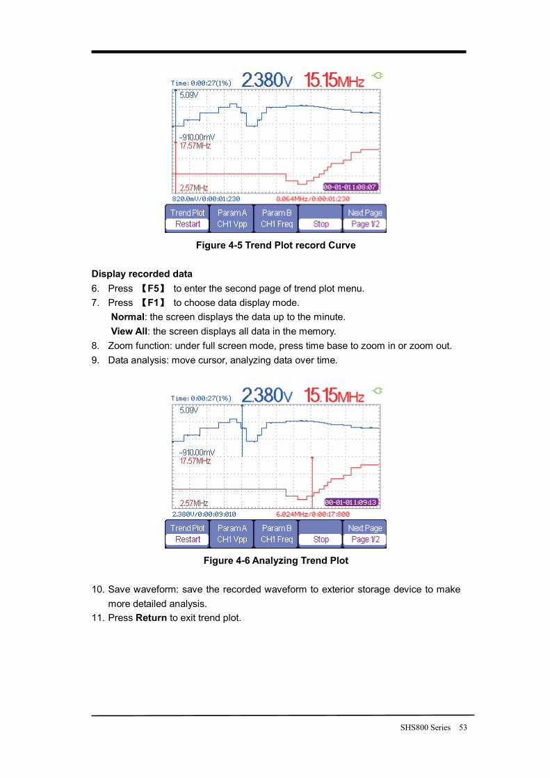
SHS800 Series 53
Figure 4-5 Trend Plot record Curve
Display recorded data 6. Press F5 to enter the second page of trend plot menu. 7. Press F1 to choose data display mode.
Normal: the screen displays the data up to the minute. View All: the screen displays all data in the memory.
8. Zoom function: under full screen mode, press time base to zoom in or zoom out. 9. Data analysis: move cursor, analyzing data over time.
Figure 4-6 Analyzing Trend Plot
10. Save waveform: save the recorded waveform to exterior storage device to make
more detailed analysis. 11. Press Return to exit trend plot.
54 SHS800 Series
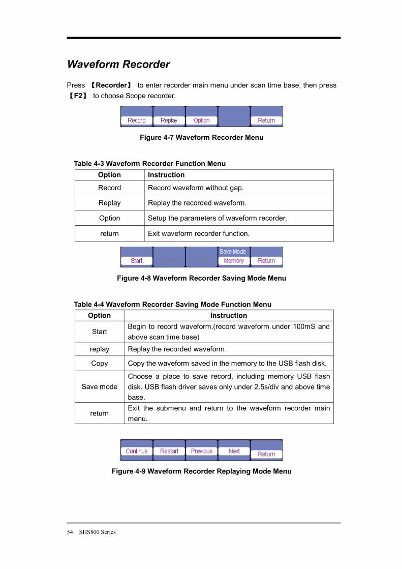
Waveform Recorder
Press Recorder to enter recorder main menu under scan time base, then press F2 to choose Scope recorder.
Figure 4-7 Waveform Recorder Menu
Table 4-3 Waveform Recorder Function Menu Option Instruction
Record Record waveform without gap.
Replay Replay the recorded waveform.
Option Setup the parameters of waveform recorder.
return Exit waveform recorder function.
Figure 4-8 Waveform Recorder Saving Mode Menu
Table 4-4 Waveform Recorder Saving Mode Function Menu Option Instruction
Start Begin to record waveform.(record waveform under 100mS and above scan time base)
replay Replay the recorded waveform.
Copy Copy the waveform saved in the memory to the USB flash disk.
Save mode Choose a place to save record, including memory USB flash disk. USB flash driver saves only under 2.5s/div and above time base.
return Exit the submenu and return to the waveform recorder main menu.
Figure 4-9 Waveform Recorder Replaying Mode Menu
SHS800 Series 55
Table 4-5 Waveform Recorder Replaying Mode Function Menu Option Instruction
Stop/Continue Pause or contnue playing waveform automatically, you can change the time base to observe the waveform in the memory.
Restart Replay the waveform
Previous Back the waveform and then play.
Next Speed the playing of the waveform. Return Exit the replaying menu.
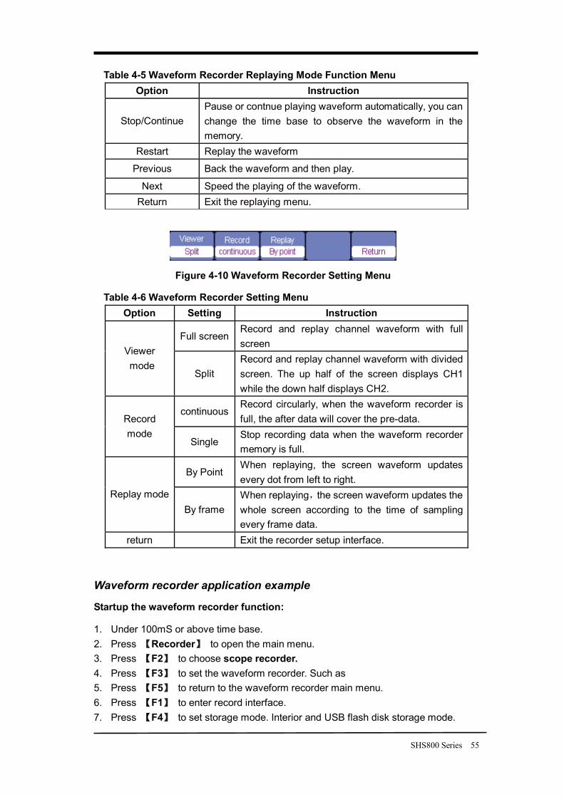
Figure 4-10 Waveform Recorder Setting Menu
Table 4-6 Waveform Recorder Setting Menu Option Setting Instruction
Full screen Record and replay channel waveform with full screen
Viewer mode
Split Record and replay channel waveform with divided screen. The up half of the screen displays CH1 while the down half displays CH2.
continuous Record circularly, when the waveform recorder is full, the after data will cover the pre-data. Record
mode Single
Stop recording data when the waveform recorder memory is full.
By Point When replaying, the screen waveform updates every dot from left to right.
Replay mode By frame
When replaying the screen waveform updates the whole screen according to the time of sampling every frame data.
return Exit the recorder setup interface.
Waveform recorder application example
Startup the waveform recorder function:
1. Under 100mS or above time base. 2. Press Recorder to open the main menu. 3. Press F2 to choose scope recorder. 4. Press F3 to set the waveform recorder. Such as 5. Press F5 to return to the waveform recorder main menu. 6. Press F1 to enter record interface. 7. Press F4 to set storage mode. Interior and USB flash disk storage mode.
56 SHS800 Series
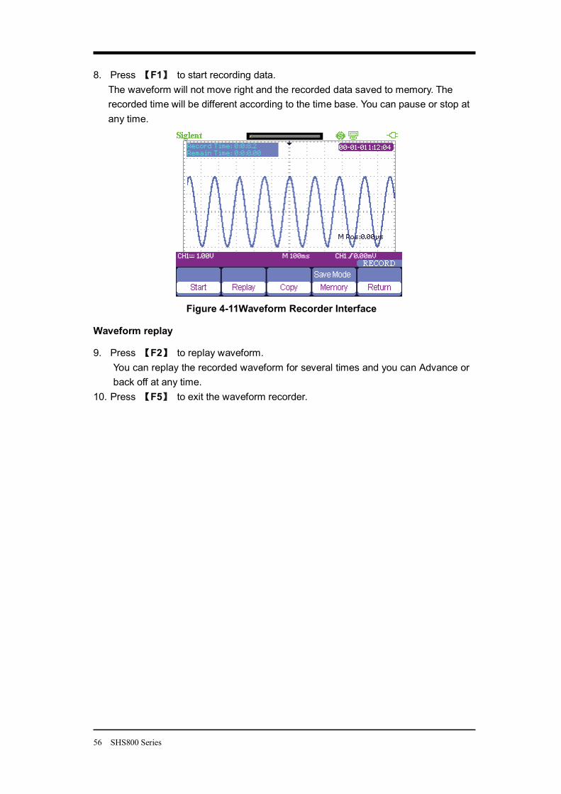
8. Press F1 to start recording data. The waveform will not move right and the recorded data saved to memory. The recorded time will be different according to the time base. You can pause or stop at any time.
Figure 4-11Waveform Recorder Interface
Waveform replay
9. Press F2 to replay waveform. You can replay the recorded waveform for several times and you can Advance or back off at any time.
10. Press F5 to exit the waveform recorder.
SHS800 Series 57
Multimeter Trend Plot
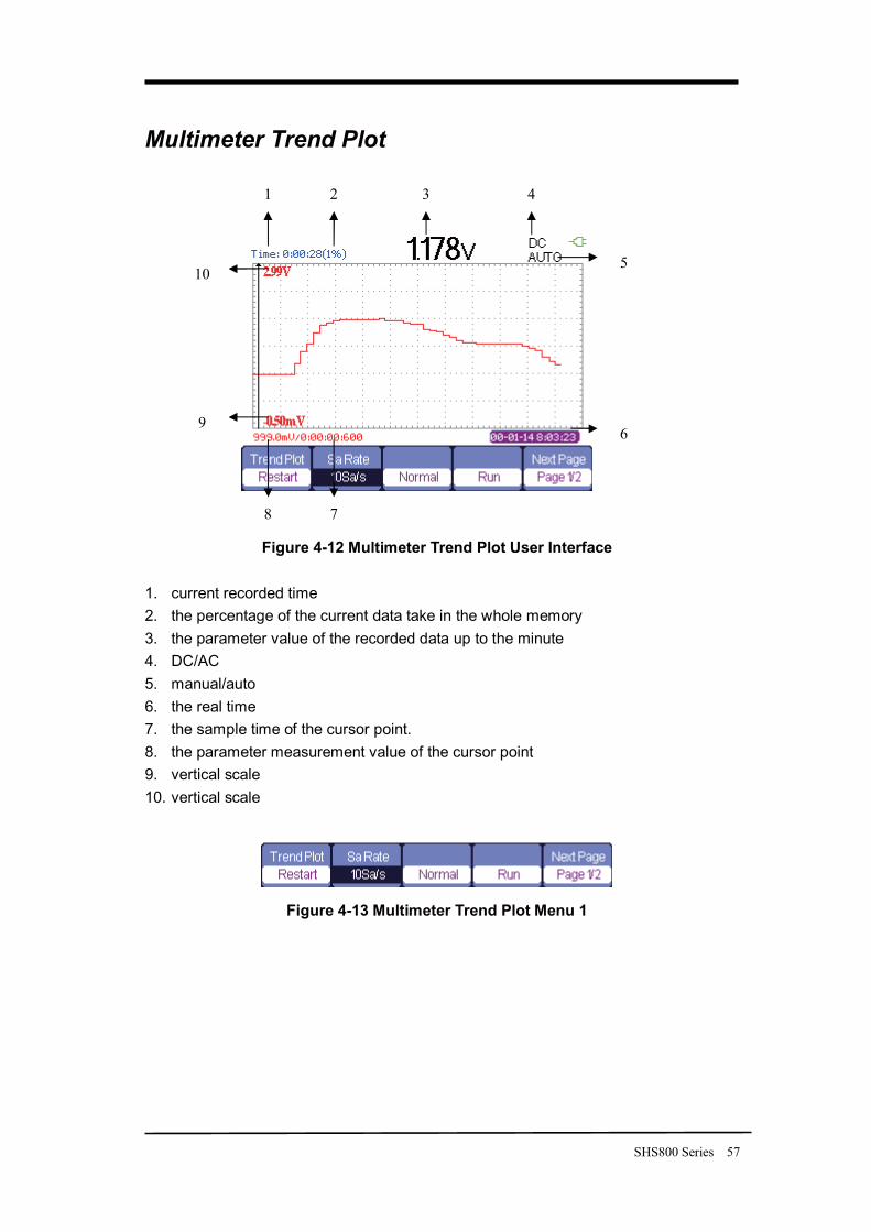
Figure 4-12 Multimeter Trend Plot User Interface
1. current recorded time 2. the percentage of the current data take in the whole memory 3. the parameter value of the recorded data up to the minute 4. DC/AC 5. manual/auto 6. the real time 7. the sample time of the cursor point. 8. the parameter measurement value of the cursor point 9. vertical scale 10. vertical scale
Figure 4-13 Multimeter Trend Plot Menu 1
2 3 4
7 8
1
5
6 9
10
58 SHS800 Series
Table 4-6 Multimeter Trend Plot Function Menu 1 function setting Instruction
Restart Quilt the current data and start to record afresh.
Sa Rate 10Sa…0.005Sa Set sampling rate normal Display the recorded data up to the minute. Display
mode All view Display all dots. Run Record data automatically Record
mode Stop Stop record data Next Page Page1/2 Enter the second page of the menu.
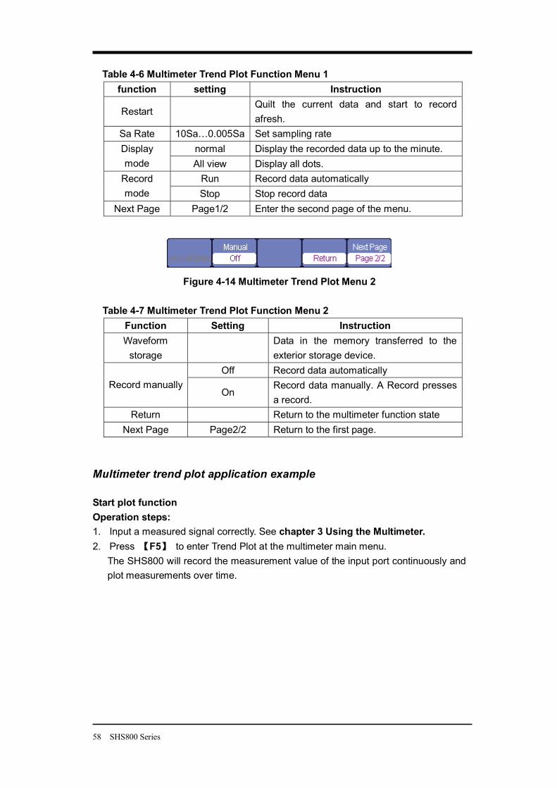
Figure 4-14 Multimeter Trend Plot Menu 2
Table 4-7 Multimeter Trend Plot Function Menu 2 Function Setting Instruction Waveform
storage
Data in the memory transferred to the exterior storage device.
Off Record data automatically Record manually
On Record data manually. A Record presses a record.
Return Return to the multimeter function state Next Page Page2/2 Return to the first page.
Multimeter trend plot application example Start plot function Operation steps: 1. Input a measured signal correctly. See chapter 3 Using the Multimeter. 2. Press F5 to enter Trend Plot at the multimeter main menu.
The SHS800 will record the measurement value of the input port continuously and plot measurements over time.
SHS800 Series 59
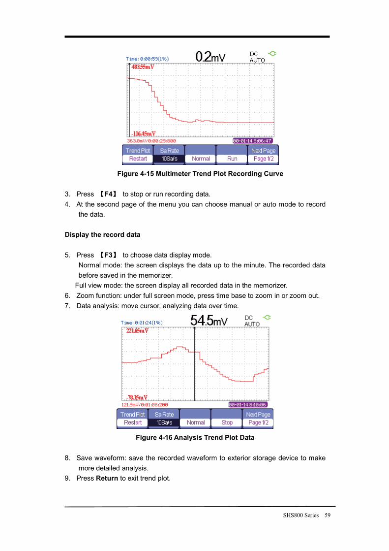
Figure 4-15 Multimeter Trend Plot Recording Curve
3. Press F4 to stop or run recording data. 4. At the second page of the menu you can choose manual or auto mode to record
the data. Display the record data 5. Press F3 to choose data display mode.
Normal mode: the screen displays the data up to the minute. The recorded data before saved in the memorizer.
Full view mode: the screen display all recorded data in the memorizer. 6. Zoom function: under full screen mode, press time base to zoom in or zoom out. 7. Data analysis: move cursor, analyzing data over time.
Figure 4-16 Analysis Trend Plot Data
8. Save waveform: save the recorded waveform to exterior storage device to make
more detailed analysis. 9. Press Return to exit trend plot.
60 SHS800 Series
Chapter 5 Prompting and Troubleshooting About this Chapter
This chapter gives a detailed instruction of every system prompting appears on the screen as well as some basic troubleshooting.
System Prompting Messages Instruction
� Trig level at limit! : Mention you that the trigger level is at a limit when you turn the Trig level knob.
� Horizon position at limit! : Mention you that the horizontal position is at a limit when you turn the horizon position knob.
� Volts/Div at limit! : Mention you that the vertical voltage have already touched the Min 2mV/div or the Max 100V/div.
� Volts position at limit! : The system would display this information when the vertical position is at a limit.
� Sec/Div at limit! : Prompts that the Volts/Div is at full range while turning the vertical scale knob.
� Holdoff time at limit! : Use the arrow keys when holdoff time has been to max or min value, now the system will clew this information.
� Function isn’t useable! : Under several special modes, the some functions could not be running.
� No signal! : The system would clew this information when the signal could not match the auto set condition. (Using in the auto set)
� Adjust at limit! : You could adjust the pulse width by the arrow keys till the pulse width has reached min20.0ns or max 10.0s.
� Location Empty! : If you have no stored waveforms or setups on some location, the screen will display this information when you press the “Recall” button on this location.
� USB Flash Drive Plug In! : This information will appear when you invert the USB Flash Drive to the USB Host port.
� USB Flash Drive Pull Out! : This information will appear when you pull out the USB Flash Drive.
� Store Data Success! : Save setup data, waveform data or Figure data to the

SHS800 Series 61
internal of the oscilloscope or USB flash successful.
� Ready Data Success! : Read setup data or waveform data from the internal of the oscilloscope or USB flash successful.
� Please set USB Device to printer! : Press the “S/div” knob will appear this information on the screen when the “Print Key” option is set to “Print Figure” and the “USB Device” option is set to “Computer”.
� USB Flash Drive isn’t connected! : When the “Save To” option is set to “File” or the “Print Key” option is set to “Save Figure” in “Save/Recall” menu , Press the “Save” option button or the “S/div” knob before inverting the USB Flash Drive to the USB Host port will appear this information on the screen.
� Record Wave Success! This message will appear when you finish recording waveforms.
62 SHS800 Series
Troubleshooting
1. After the SHS800 is powered on if the screen remains dark please do as following steps
1) Check the power cable’s connection.
2) Ensure the power switch is turned on.
3) After the inspections above restart the Handheld Digital Oscilloscope.
4) If the Handheld Digital Oscilloscope is still not used after the checking, please connect with MY company
2. If there is no signal wave in the screen after gathering the signal, please do as following steps:
1) Check the probe connecting with the signal cable or not
2) Check the signal cable connecting with the BNC connector or not.
3) Check the probe whether connect with the goods tested or not.
4) Check the tested goods produce the signal or not.
5) Gather the signal again.
3. The value of the tested voltage is 10 times higher/lower than the real one , please do as following steps:
Check the attenuation quotient whether match the probe attenuation proportion or
not.
4. Display the wave, but not steady , please do as following steps:
1) Check the signal source on the trigger interface whether or not matches the signal channel.
2) Check the trigger mode: normal signal should use the “edge” trigger mode. The video signal should use the “Video” Trigger mode. The signal would display steady, only using the matching trigger mode.
3) Attempt to change the “ coupling” into “HF Reject” or “LF Reject” display, so that the High/low frequency noise disturb the trigger should be filtrated
5. Press “RUN/STOP” button, but no display.
Check the trigger mode on the trigger interface whether or not in the “normal” or “single”, and check the trigger level is whether or not over the wave range. If yes, please put the trigger level to the middle position or set the trigger mode to the “Auto” position. In another hand, you could choose the “Auto” button to set up automatically.
SHS800 Series 63
6. The signal is displayed as ladder like waveform
1) This phenomenon is normal. The time base maybe is too slow .you should turn the horizontal SCALE knob to increase horizontal resolution to improve the display.
2) Maybe the display Type is set to “Vectors”, You could set it to Dots mode to improve the display.
7. The multimeter measurements aren’t correct
1) Check that if the range of the SHS800 matches with the measured item.
2) Make sure that if the multimeter is beyond the calibration date. if the measurements and the real values are beyond the relevant precision, please contact with the calibration site warranted by SIGLENT company to calibrate the SHS800 .
3) If you can’t use the SHS800 normally all the same, please contact with SIGLENT servicing center, we will provide service for you.
8. The other kind of trouble, please contact with SIGLENT servicing center. For more details please see service and support.
Warning Person without warranty by SIGLENT Company shouldn’t disconnect the machine for inspection or you will lose the quality guarantee.
64 SHS800 Series
Chapter 6 Service and Support About this Chapter
This chapter covers basic maintain procedures that can be performed by the user. You should have a detailed understanding of the content below to use and maintain you legal rights.
Maintain Summary
Each SIGLENT product is warranted to be free from defects in material and workmanship under normal use and service. The warranty period is three years and begins on the data of shipment. This warranty extends only to the original buyer or ender-user c of a SIGLENT authorized reseller. If a product or CRT proves defective within the warranty period, SIGLENT will provide repair or replacement as described in the complete warranty statement.
To arrange for service or obtain a copy of the complete warranty statement, please contact with the nearest SIGLENT sale and service office.
Except this summary or the applicable warranty statement, SIGLENT makes no warranty of any kind of express or implied, including without limitation the implied warranties of merchantability and fitness for a particular purpose. In no event shall SIGLENT be liable for indirect, special or consequential damages.
Contact with SIGLENT
SHENZHEN SIGLENT TECHNOLOYIES CO., LTD Address: 3/F , No. 4 BUILDING, 3rd LIUXIAN Rd, ANTONGDA INDUSTRY GARDEN, BAO’AN DISTRICT, SHENZHEN,518101, CHINA
Tel: 0086 755 36615186 E-mail: [email protected] http://www.siglent.com
SHS800 Series 65
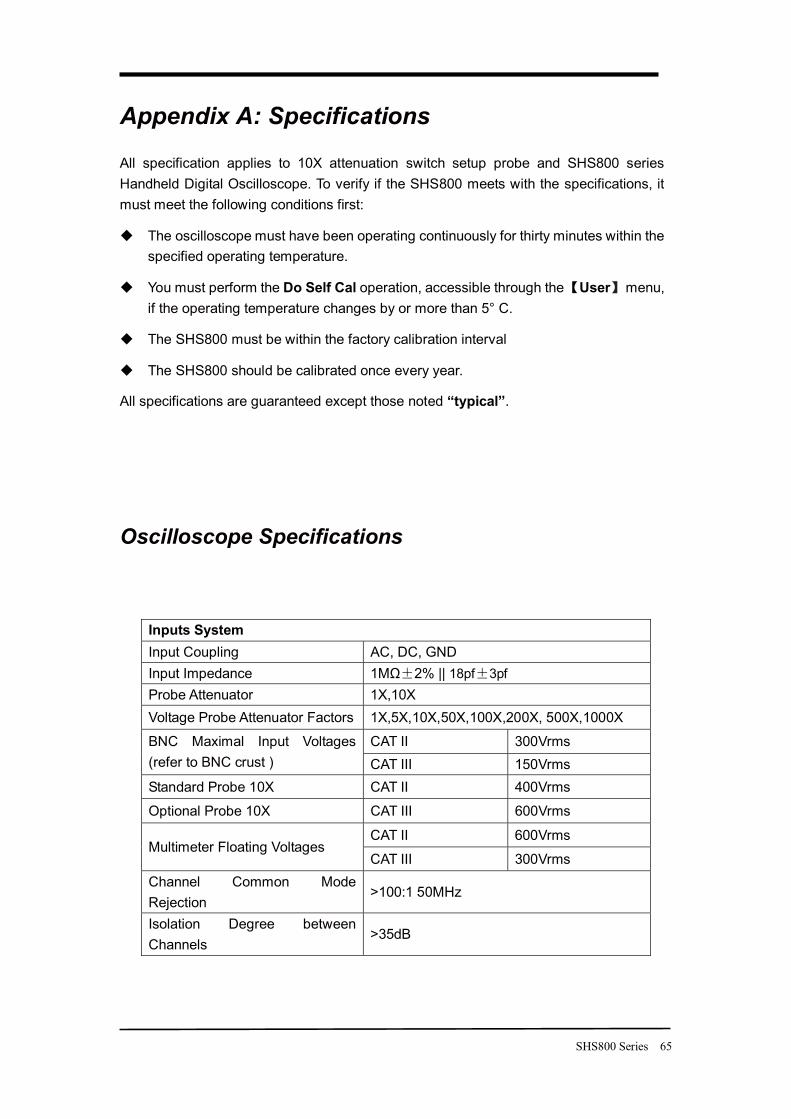
Appendix A: Specifications
All specification applies to 10X attenuation switch setup probe and SHS800 series Handheld Digital Oscilloscope. To verify if the SHS800 meets with the specifications, it must meet the following conditions first:
� The oscilloscope must have been operating continuously for thirty minutes within the specified operating temperature.
� You must perform the Do Self Cal operation, accessible through the User menu, if the operating temperature changes by or more than 5° C.
� The SHS800 must be within the factory calibration interval
� The SHS800 should be calibrated once every year.
All specifications are guaranteed except those noted “typical”.
Oscilloscope Specifications
Inputs System Input Coupling AC, DC, GND Input Impedance 1MΩ 2% || 18pf 3pf Probe Attenuator 1X,10X Voltage Probe Attenuator Factors 1X,5X,10X,50X,100X,200X, 500X,1000X
CAT II 300Vrms BNC Maximal Input Voltages (refer to BNC crust ) CAT III 150Vrms Standard Probe 10X CAT II 400Vrms
Optional Probe 10X CAT III 600Vrms
CAT II 600Vrms Multimeter Floating Voltages
CAT III 300Vrms Channel Common Mode Rejection
>100:1 50MHz
Isolation Degree between Channels
>35dB
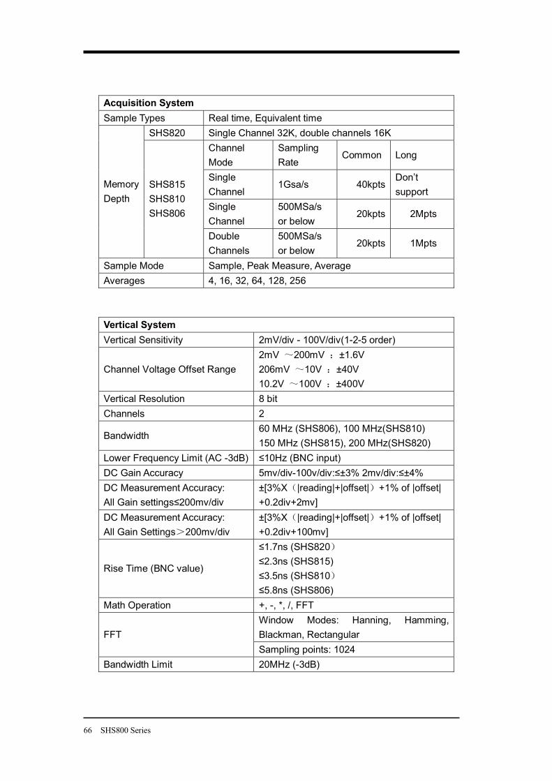
66 SHS800 Series
Acquisition System Sample Types Real time, Equivalent time
SHS820 Single Channel 32K, double channels 16K Channel Mode
Sampling Rate
Common Long
Single Channel
1Gsa/s 40kpts Don’t support
Single Channel
500MSa/s or below
20kpts 2Mpts
Memory Depth
SHS815 SHS810 SHS806
Double Channels
500MSa/s or below
20kpts 1Mpts
Sample Mode Sample, Peak Measure, Average Averages 4, 16, 32, 64, 128, 256
Vertical System Vertical Sensitivity 2mV/div - 100V/div(1-2-5 order)
Channel Voltage Offset Range 2mV 200mV ±1.6V 206mV 10V ±40V 10.2V 100V ±400V
Vertical Resolution 8 bit Channels 2
Bandwidth 60 MHz (SHS806), 100 MHz(SHS810) 150 MHz (SHS815), 200 MHz(SHS820)
Lower Frequency Limit (AC -3dB) ≤10Hz (BNC input) DC Gain Accuracy 5mv/div-100v/div:≤±3% 2mv/div:≤±4% DC Measurement Accuracy: All Gain settings≤200mv/div
±[3%X |reading|+|offset| +1% of |offset| +0.2div+2mv]
DC Measurement Accuracy: All Gain Settings 200mv/div
±[3%X |reading|+|offset| +1% of |offset| +0.2div+100mv]
Rise Time (BNC value)
≤1.7ns (SHS820 ≤2.3ns (SHS815) ≤3.5ns (SHS810 ≤5.8ns (SHS806)
Math Operation +, -, *, /, FFT Window Modes: Hanning, Hamming, Blackman, Rectangular FFT Sampling points: 1024
Bandwidth Limit 20MHz (-3dB)
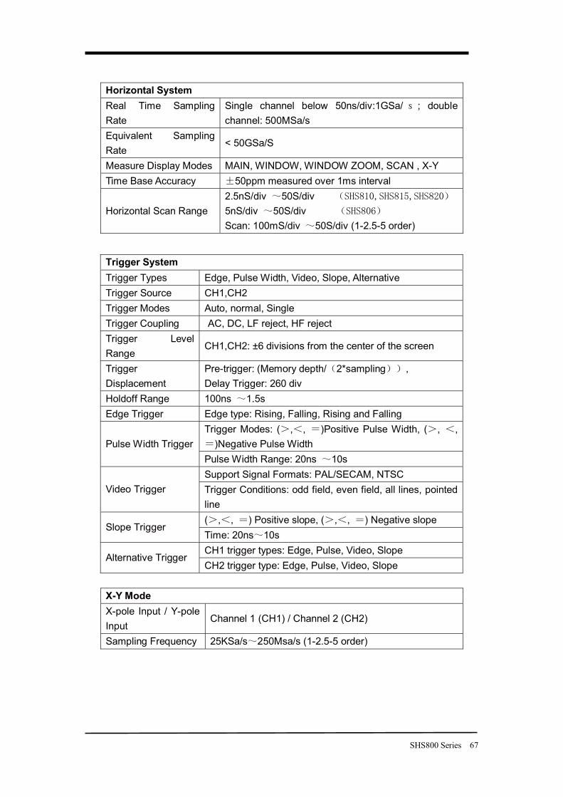
SHS800 Series 67
Horizontal System Real Time Sampling Rate
Single channel below 50ns/div:1GSa/ ; double channel: 500MSa/s
Equivalent Sampling Rate
< 50GSa/S
Measure Display Modes MAIN, WINDOW, WINDOW ZOOM, SCAN , X-Y Time Base Accuracy 50ppm measured over 1ms interval
Horizontal Scan Range 2.5nS/div 50S/div 5nS/div 50S/div Scan: 100mS/div 50S/div (1-2.5-5 order)
X-Y Mode X-pole Input / Y-pole Input
Channel 1 (CH1) / Channel 2 (CH2)
Sampling Frequency 25KSa/s 250Msa/s (1-2.5-5 order)
Trigger System Trigger Types Edge, Pulse Width, Video, Slope, Alternative Trigger Source CH1,CH2 Trigger Modes Auto, normal, Single Trigger Coupling AC, DC, LF reject, HF reject Trigger Level Range
CH1,CH2: ±6 divisions from the center of the screen
Trigger Displacement
Pre-trigger: (Memory depth/ 2*sampling , Delay Trigger: 260 div
Holdoff Range 100ns 1.5s Edge Trigger Edge type: Rising, Falling, Rising and Falling
Trigger Modes: ( , , )Positive Pulse Width, ( , , )Negative Pulse Width Pulse Width Trigger
Pulse Width Range: 20ns 10s Support Signal Formats: PAL/SECAM, NTSC
Video Trigger Trigger Conditions: odd field, even field, all lines, pointed line ( , , ) Positive slope, ( , , ) Negative slope
Slope Trigger Time: 20ns 10s CH1 trigger types: Edge, Pulse, Video, Slope
Alternative Trigger CH2 trigger type: Edge, Pulse, Video, Slope
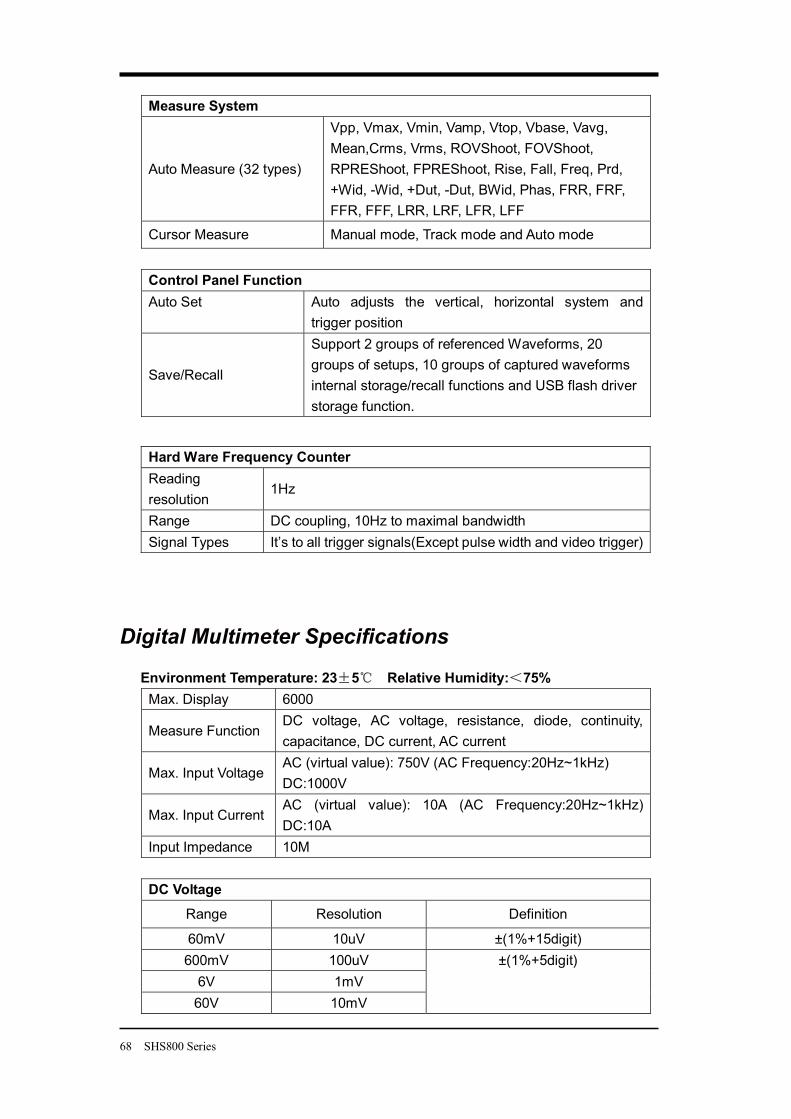
68 SHS800 Series
Measure System
Auto Measure (32 types)
Vpp, Vmax, Vmin, Vamp, Vtop, Vbase, Vavg, Mean,Crms, Vrms, ROVShoot, FOVShoot, RPREShoot, FPREShoot, Rise, Fall, Freq, Prd, +Wid, -Wid, +Dut, -Dut, BWid, Phas, FRR, FRF, FFR, FFF, LRR, LRF, LFR, LFF
Cursor Measure Manual mode, Track mode and Auto mode
Control Panel Function Auto Set
Auto adjusts the vertical, horizontal system and trigger position
Save/Recall
Support 2 groups of referenced Waveforms, 20 groups of setups, 10 groups of captured waveforms internal storage/recall functions and USB flash driver storage function.
Digital Multimeter Specifications
Environment Temperature: 23 5 Relative Humidity: 75% Max. Display 6000
Measure Function DC voltage, AC voltage, resistance, diode, continuity, capacitance, DC current, AC current
Max. Input Voltage AC (virtual value): 750V (AC Frequency:20Hz~1kHz) DC:1000V
Max. Input Current AC (virtual value): 10A (AC Frequency:20Hz~1kHz) DC:10A
Input Impedance 10M
DC Voltage
Range Resolution Definition
60mV 10uV ±(1%+15digit) 600mV 100uV
6V 1mV 60V 10mV
±(1%+5digit)
Hard Ware Frequency Counter Reading resolution
1Hz
Range DC coupling, 10Hz to maximal bandwidth Signal Types It’s to all trigger signals(Except pulse width and video trigger)
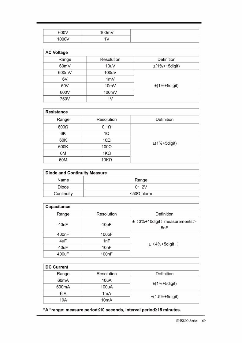
SHS800 Series 69
600V 100mV 1000V 1V
AC Voltage
Range Resolution Definition 60mV 10uV ±(1%+15digit) 600mV 100uV
6V 1mV 60V 10mV 600V 100mV 750V 1V
±(1%+5digit)
Resistance
Range Resolution Definition
600Ω 0.1Ω 6K 1Ω 60K 10Ω 600K 100Ω 6M 1KΩ 60M 10KΩ
±(1%+5digit)
Diode and Continuity Measure
Name Range Diode 0 2V
Continuity <50Ω alarm
Capacitance Range Resolution Definition
40nF 10pF ± 3%+10digit measurements
5nF 400nF 100pF 4uF 1nF 40uF 10nF 400uF 100nF
± 4%+5digit
DC Current
Range Resolution Definition 60mA 10uA 600mA 100uA
±(1%+5digit)
6 A 1mA 10A 10mA
±(1.5%+5digit)
“A “range: measure period≤10 seconds, interval period≥15 minutes.
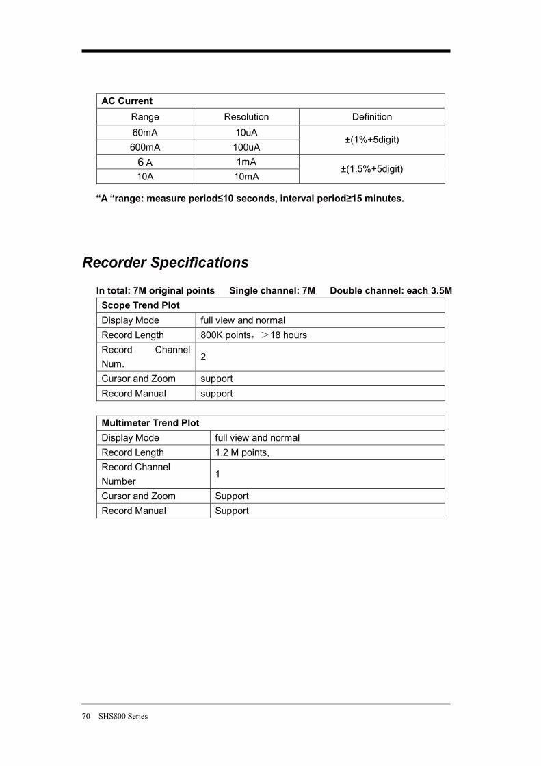
70 SHS800 Series
AC Current Range Resolution Definition 60mA 10uA 600mA 100uA
±(1%+5digit)
6 A 1mA 10A 10mA
±(1.5%+5digit)
“A “range: measure period≤10 seconds, interval period≥15 minutes.
Recorder Specifications
In total: 7M original points Single channel: 7M Double channel: each 3.5M Scope Trend Plot Display Mode full view and normal Record Length 800K points 18 hours Record Channel Num.
2
Cursor and Zoom support Record Manual support
Multimeter Trend Plot Display Mode full view and normal Record Length 1.2 M points, Record Channel Number
1
Cursor and Zoom Support Record Manual Support
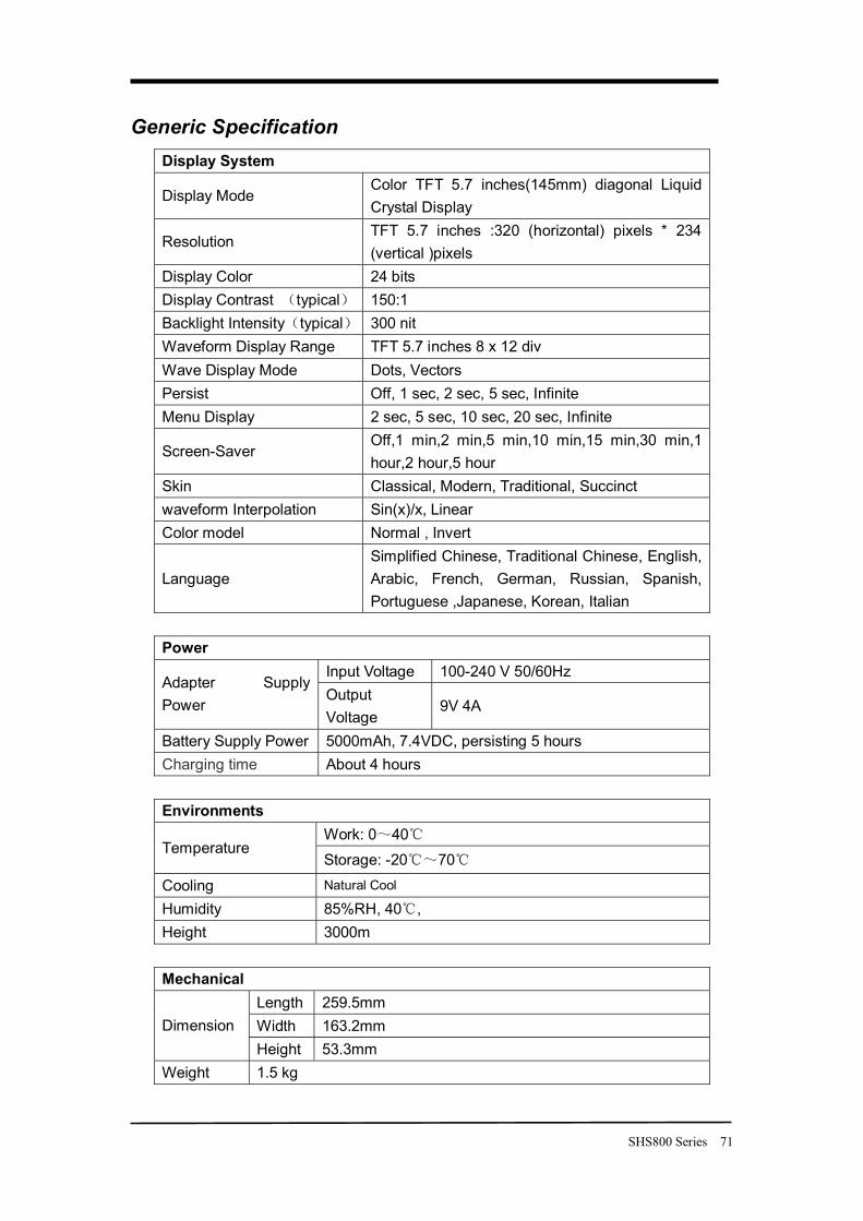
SHS800 Series 71
Generic Specification Display System
Display Mode Color TFT 5.7 inches(145mm) diagonal Liquid Crystal Display
Resolution TFT 5.7 inches :320 (horizontal) pixels * 234 (vertical )pixels
Display Color 24 bits Display Contrast typical 150:1 Backlight Intensity typical 300 nit Waveform Display Range TFT 5.7 inches 8 x 12 div Wave Display Mode Dots, Vectors Persist Off, 1 sec, 2 sec, 5 sec, Infinite Menu Display 2 sec, 5 sec, 10 sec, 20 sec, Infinite
Screen-Saver Off,1 min,2 min,5 min,10 min,15 min,30 min,1 hour,2 hour,5 hour
Skin Classical, Modern, Traditional, Succinct waveform Interpolation Sin(x)/x, Linear Color model Normal , Invert
Language Simplified Chinese, Traditional Chinese, English, Arabic, French, German, Russian, Spanish, Portuguese ,Japanese, Korean, Italian
Power
Input Voltage 100-240 V 50/60Hz Adapter Supply Power
Output Voltage
9V 4A
Battery Supply Power 5000mAh, 7.4VDC, persisting 5 hours Charging time About 4 hours
Environments
Work: 0 40 Temperature
Storage: -20 70
Cooling Natural Cool Humidity 85%RH, 40 , Height 3000m
Mechanical
Length 259.5mm Width 163.2mm Dimension Height 53.3mm
Weight 1.5 kg
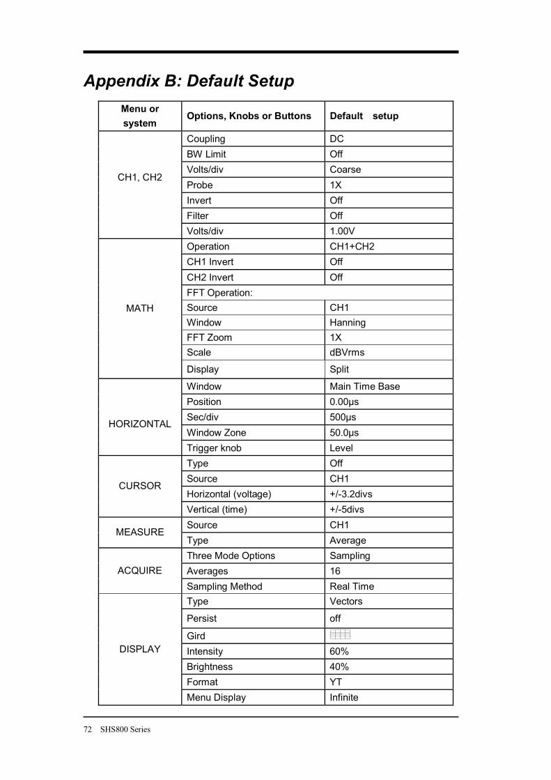
72 SHS800 Series
Appendix B: Default Setup Menu or system
Options, Knobs or Buttons Default setup
Coupling DC BW Limit Off Volts/div Coarse Probe 1X Invert Off Filter Off
CH1, CH2
Volts/div 1.00V Operation CH1+CH2 CH1 Invert Off CH2 Invert Off FFT Operation: Source CH1 Window Hanning FFT Zoom 1X Scale dBVrms
MATH
Display Split
Window Main Time Base Position 0.00μs Sec/div 500μs Window Zone 50.0μs
HORIZONTAL
Trigger knob Level Type Off Source CH1 Horizontal (voltage) +/-3.2divs
CURSOR
Vertical (time) +/-5divs Source CH1
MEASURE Type Average Three Mode Options Sampling Averages 16 ACQUIRE Sampling Method Real Time Type Vectors
Persist off
Gird Intensity 60% Brightness 40% Format YT
DISPLAY
Menu Display Infinite
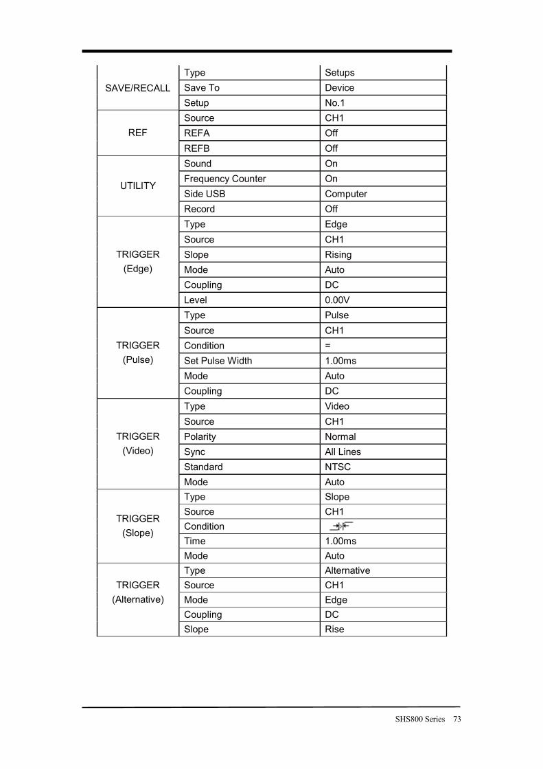
SHS800 Series 73
Type Setups Save To Device SAVE/RECALL Setup No.1 Source CH1 REFA Off REF REFB Off Sound On Frequency Counter On Side USB Computer
UTILITY
Record Off Type Edge Source CH1 Slope Rising Mode Auto Coupling DC
TRIGGER (Edge)
Level 0.00V Type Pulse Source CH1 Condition = Set Pulse Width 1.00ms Mode Auto
TRIGGER (Pulse)
Coupling DC Type Video Source CH1 Polarity Normal Sync All Lines Standard NTSC
TRIGGER (Video)
Mode Auto Type Slope Source CH1 Condition Time 1.00ms
TRIGGER (Slope)
Mode Auto Type Alternative Source CH1 Mode Edge
TRIGGER (Alternative)
Coupling DC Slope Rise
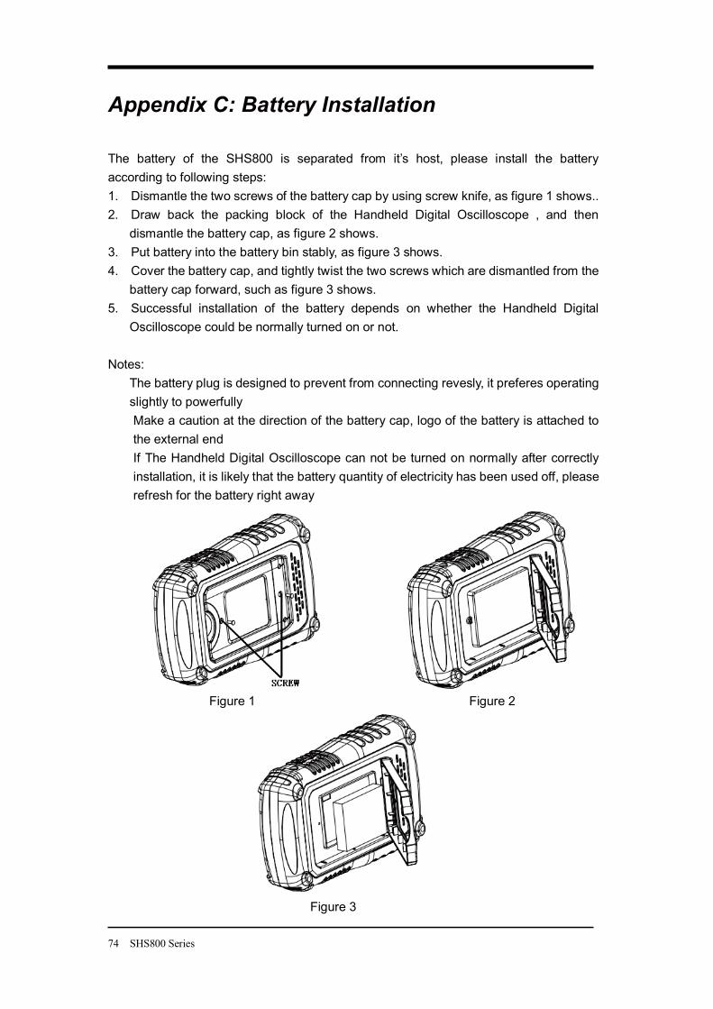
74 SHS800 Series
Appendix C: Battery Installation The battery of the SHS800 is separated from it’s host, please install the battery according to following steps: 1. Dismantle the two screws of the battery cap by using screw knife, as figure 1 shows.. 2. Draw back the packing block of the Handheld Digital Oscilloscope , and then
dismantle the battery cap, as figure 2 shows. 3. Put battery into the battery bin stably, as figure 3 shows. 4. Cover the battery cap, and tightly twist the two screws which are dismantled from the
battery cap forward, such as figure 3 shows. 5. Successful installation of the battery depends on whether the Handheld Digital
Oscilloscope could be normally turned on or not.
Notes: The battery plug is designed to prevent from connecting revesly, it preferes operating slightly to powerfully Make a caution at the direction of the battery cap, logo of the battery is attached to the external end If The Handheld Digital Oscilloscope can not be turned on normally after correctly installation, it is likely that the battery quantity of electricity has been used off, please refresh for the battery right away
Figure 1 Figure 2 Figure 3
SHS800 Series 75
Appendix D: Daily Maintaining and Cleaning
Daily Maintaining
Do not let the LCD exposed in the sun directly for a long period when storing or placing the SHS800.
CAUTION: To avoid damage to the instrument or probes, do not expose them to sprays, liquids, or solvents
Cleaning
Check the instrument and the probes according to daily use situation. Please do the following steps to clean the surface of the instrument.
To clean the exterior surface, perform the following steps:
1. Remove loose dust on the outside of the instrument and probes with a lint-free cloth. Use care to avoid scratching the clear plastic display filter.
2. Use a soft cloth dampened with water to clean the instrument. Please disconnect it from all power sources firstly.
Note
1. To avoid damage to the surface of the instrument or probes, do not use any abrasive or chemical cleaning agents
2. To avoid water causing electric short circuit or body hurt, Make sure the instrument is completely dry before reconnecting it to a power source


![DeviceListfor BX32PBarlinoII - Batronix · 2018-04-27 · Image not found. InnovativeTools.ExcellentService. AM2732A(21V)[DIP24] Manufacturer:AMD RequiredAdapter:None Variants:AM2732A-20DC,AM2732A](https://img.pdfslide.us/doc/110x75/5f376bbbe520e562a246c996/devicelistfor-bx32pbarlinoii-batronix-2018-04-27-image-not-found-innovativetoolsexcellentservice.jpg)