Embed Size (px)
Citation preview

Software Installation and computer Setup
April 2017
Introduction
The following describes how to install the True-Trak 2020™ software on your computer
and connect the computer to the FasTrak2™ Portable through the computer's Ethernet
port. It is assumed that you are installing this on a computer of your own. If you
purchased a computer from Visi-Trak Worldwide these steps will have already been
done.
Table of Contents
1. Obtaining Your True-Trak 2020™ Software
2. Installing Your True-Trak 2020™ Software
2.1.1. Sure-Trak2™ Control System
3. Determining the TCP/IP Address of the FasTrak2™ Board
4. Setting Up the Ethernet Port on the Computer
5. Getting the Program to Talk to the FasTrak2 Board
6. Connecting the Cable to the Visi-Trak® Position Transducer
6.1. Installation Instructions for Position Transducer
7. Connecting the Cable to a Viatran Pressure Transducer
7.1. Cylinder Head
7.2. Piston Rod
8. Connecting Master Enable
9. Sure-Trak2™ Control System
9.1.1. Calibration for Servo Valve (50mm, 80mm) w/ Digital Servo Amp
10. 8 IPS (0.2 M/sec) Test Shot

Obtaining Your True-Trak 2020™ Software
You should have received an Installation USB Drive with your shipment.
The drive contains the latest version of the Visi-Trak software (Example v8.14.exe).
Double click this file which will create a directory on your computer named
C:\Installx.xx (where x.xx is the number of the latest software version. Example
C:\Install8.14).
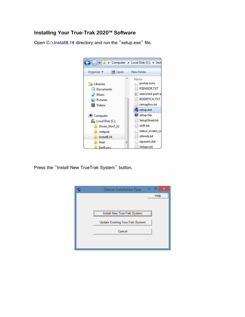
Installing Your True-Trak 2020™ Software
Open C:\Install8.14 directory and run the "setup.exe" file.
Press the "Install New TrueTrak System" button.
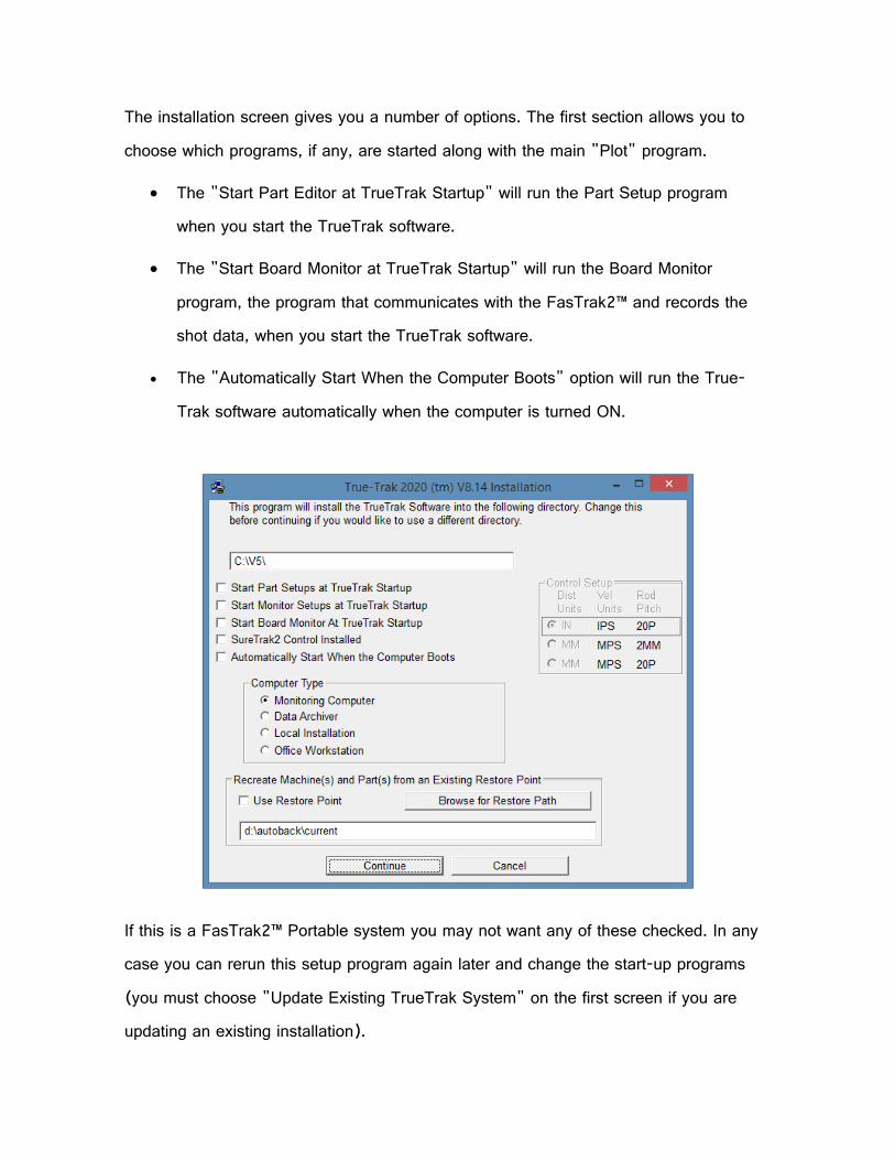
The installation screen gives you a number of options. The first section allows you to
choose which programs, if any, are started along with the main "Plot" program.
• The "Start Part Editor at TrueTrak Startup" will run the Part Setup program
when you start the TrueTrak software.
• The "Start Board Monitor at TrueTrak Startup" will run the Board Monitor
program, the program that communicates with the FasTrak2™ and records the
shot data, when you start the TrueTrak software.
• The "Automatically Start When the Computer Boots" option will run the True-
Trak software automatically when the computer is turned ON.
If this is a FasTrak2™ Portable system you may not want any of these checked. In any
case you can rerun this setup program again later and change the start-up programs
(you must choose "Update Existing TrueTrak System" on the first screen if you are
updating an existing installation).

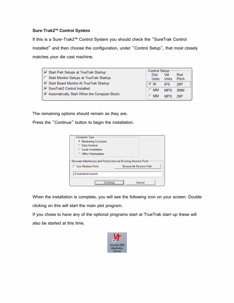
Sure-Trak2™ Control System
If this is a Sure-Trak2™ Control System you should check the "SureTrak Control
Installed" and then choose the configuration, under "Control Setup", that most closely
matches your die cast machine.
The remaining options should remain as they are.
Press the "Continue" button to begin the installation.
When the installation is complete, you will see the following icon on your screen. Double
clicking on this will start the main plot program.
If you chose to have any of the optional programs start at TrueTrak start-up these will
also be started at this time.
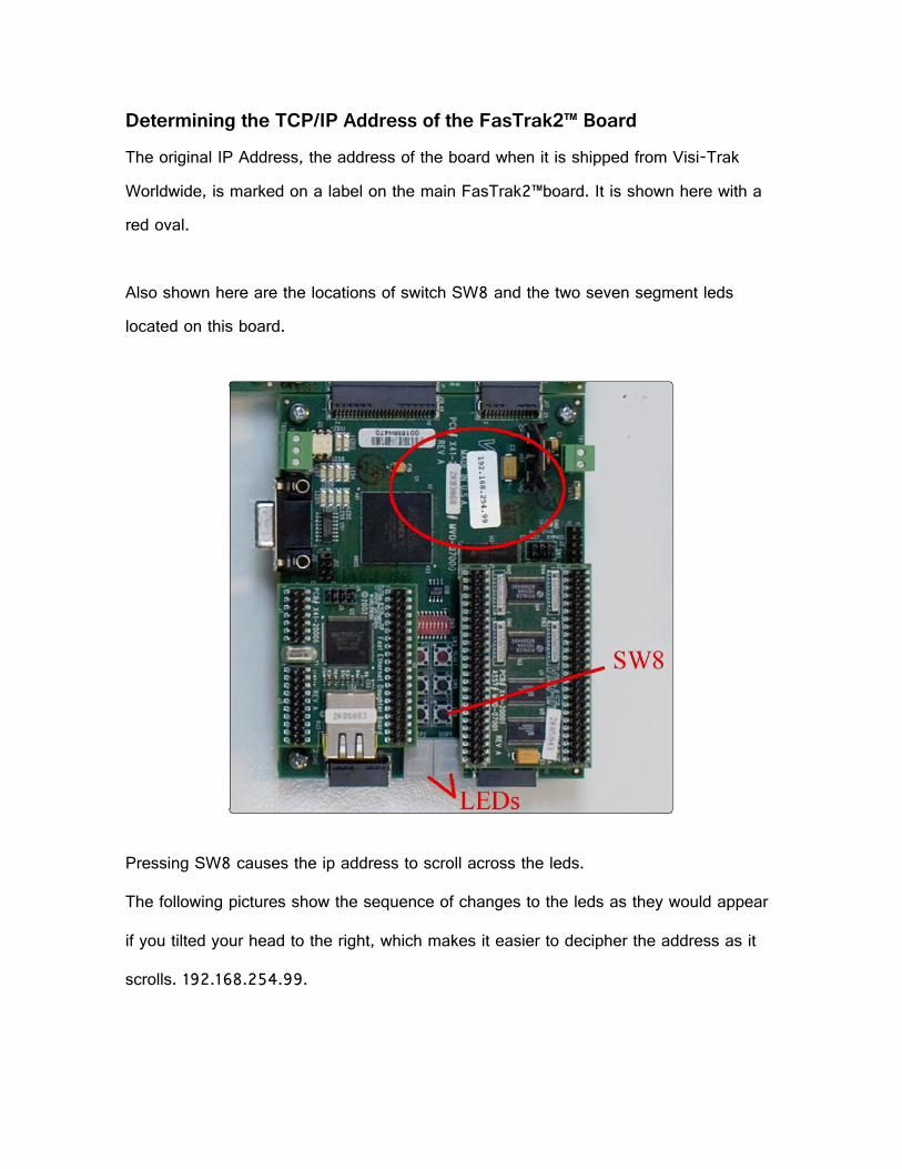
Determining the TCP/IP Address of the FasTrak2™ Board
The original IP Address, the address of the board when it is shipped from Visi-Trak
Worldwide, is marked on a label on the main FasTrak2™board. It is shown here with a
red oval.
Also shown here are the locations of switch SW8 and the two seven segment leds
located on this board.
Pressing SW8 causes the ip address to scroll across the leds.
The following pictures show the sequence of changes to the leds as they would appear
if you tilted your head to the right, which makes it easier to decipher the address as it
scrolls. 192.168.254.99.

Setting Up the Ethernet Port on the Computer
The following is a description of how to connect a FasTrak2™ Portable to a separate
computer.
If you have an integrated monitoring computer then the computer and the FasTrak2™
board are located inside the same cabinet and are normally connected by an orange
cat5 crossover cable that goes directly from the FasTrak2™ board to the "FasTrak2
Direct Connection" Ethernet port on the computer. Otherwise, the steps shown here are
the same that are performed by Visi-Trak Worldwide personnel before an integrated
system is shipped.
Plug a normal Cat5 Ethernet patch cable into the Ethernet port on the computer.
568APinoutfor568B
On the computer, open the Network Connections dialog. Right click on the Network icon
and select Open Network and Sharing Center.
Click Local Area Connection

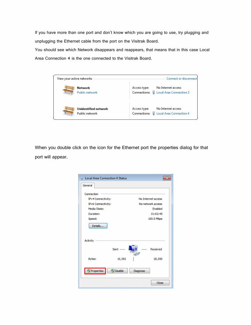
If you have more than one port and don't know which you are going to use, try plugging and
unplugging the Ethernet cable from the port on the Visitrak Board.
You should see which Network disappears and reappears, that means that in this case Local
Area Connection 4 is the one connected to the Visitrak Board.
When you double click on the icon for the Ethernet port the properties dialog for that
port will appear.

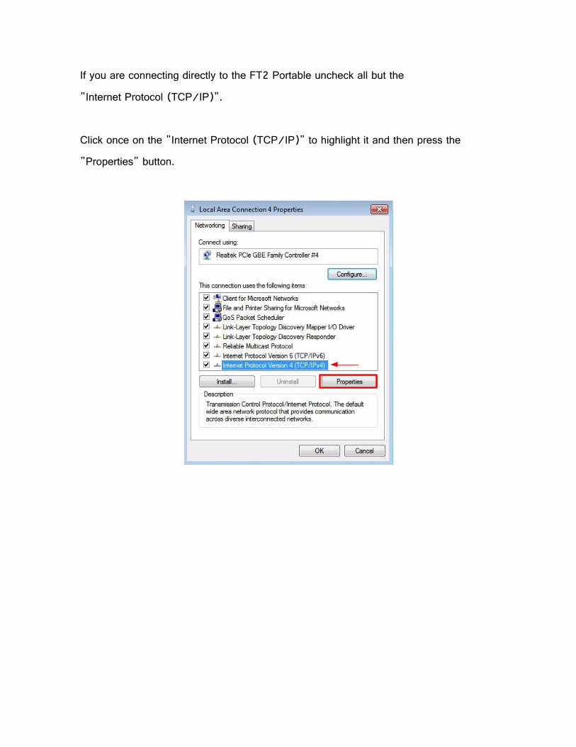
If you are connecting directly to the FT2 Portable uncheck all but the
"Internet Protocol (TCP/IP)".
Click once on the "Internet Protocol (TCP/IP)" to highlight it and then press the
"Properties" button.
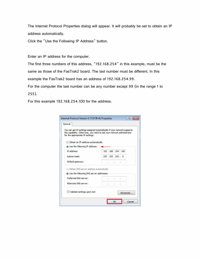
The Internet Protocol Properties dialog will appear. It will probably be set to obtain an IP
address automatically.
Click the "Use the Following IP Address" button.
Enter an IP address for the computer.
The first three numbers of this address, "192.168.254" in this example, must be the
same as those of the FasTrak2 board. The last number must be different. In this
example the FasTrak2 board has an address of 192.168.254.99.
For the computer the last number can be any number except 99 (in the range 1 to
255).
For this example 192.168.254.100 for the address.
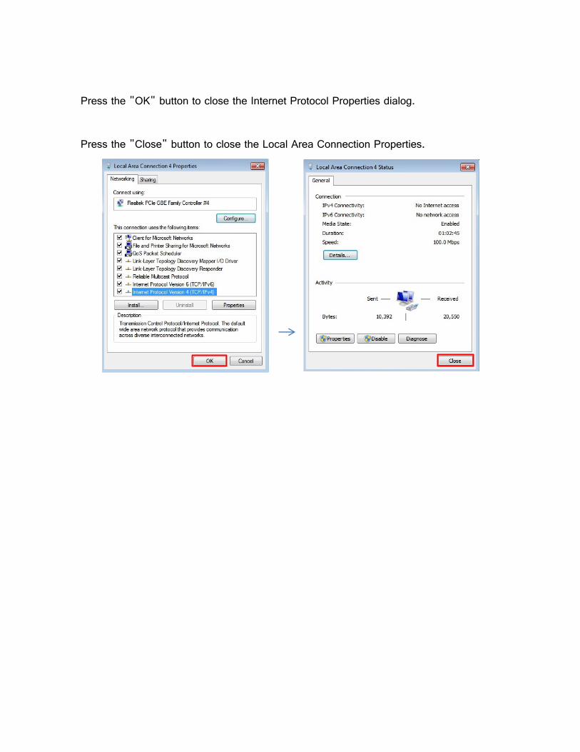
Press the "OK" button to close the Internet Protocol Properties dialog.
Press the "Close" button to close the Local Area Connection Properties.

Getting the Program to Talk to the FasTrak2 Board Make sure the Ethernet cable connects the computer to the FT2 Portable and that the
FT2
Portable is turned on.
Start the True-Trak program on the computer.
If the "FasTrak2" program is running, pull down the "File" menu and choose "Exit and
STOP Monitoring" to shut the program down.
Pull down the "Monitor" menu and choose "FasTrak Board Setup".
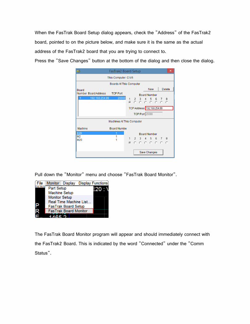
When the FasTrak Board Setup dialog appears, check the "Address" of the FasTrak2
board, pointed to on the picture below, and make sure it is the same as the actual
address of the FasTrak2 board that you are trying to connect to.
Press the "Save Changes" button at the bottom of the dialog and then close the dialog.
Pull down the "Monitor" menu and choose "FasTrak Board Monitor".
The FasTrak Board Monitor program will appear and should immediately connect with
the FasTrak2 Board. This is indicated by the word "Connected" under the "Comm
Status".

If this is the first time you have connected to this FasTrak2 board you will see the
"Monitor Status" display "Uploading..." for a second or two and then it will display
"Upload Complete".
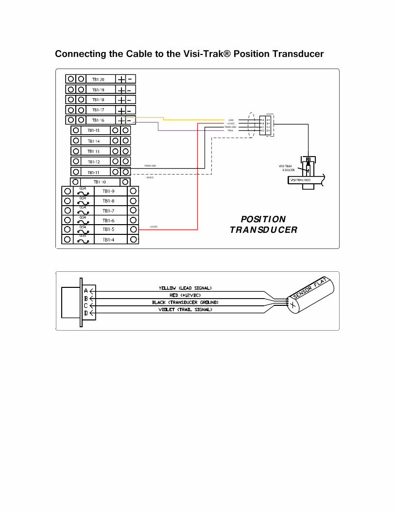
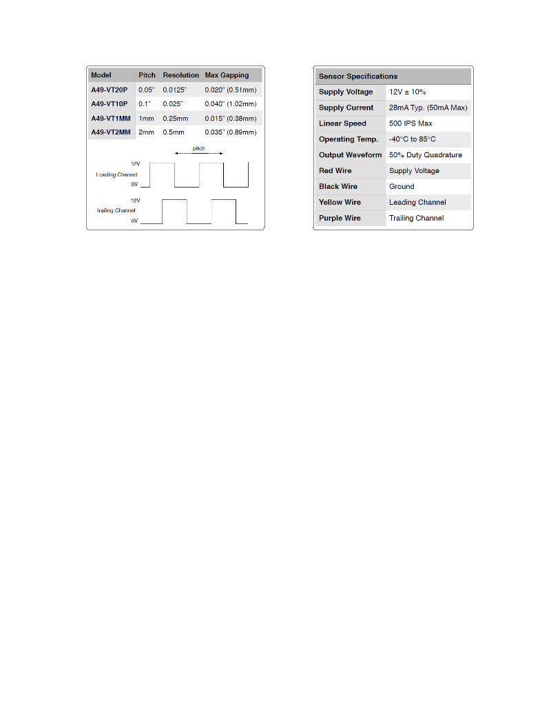
Connecting the Cable to the Visi-Trak® Position Transducer
ABCD
ABCD
LEAD+12VDC
TRANSGNDTRAIL
+12VDC
TRANSGND
SHIELD
POSITION TRAN SD U CER
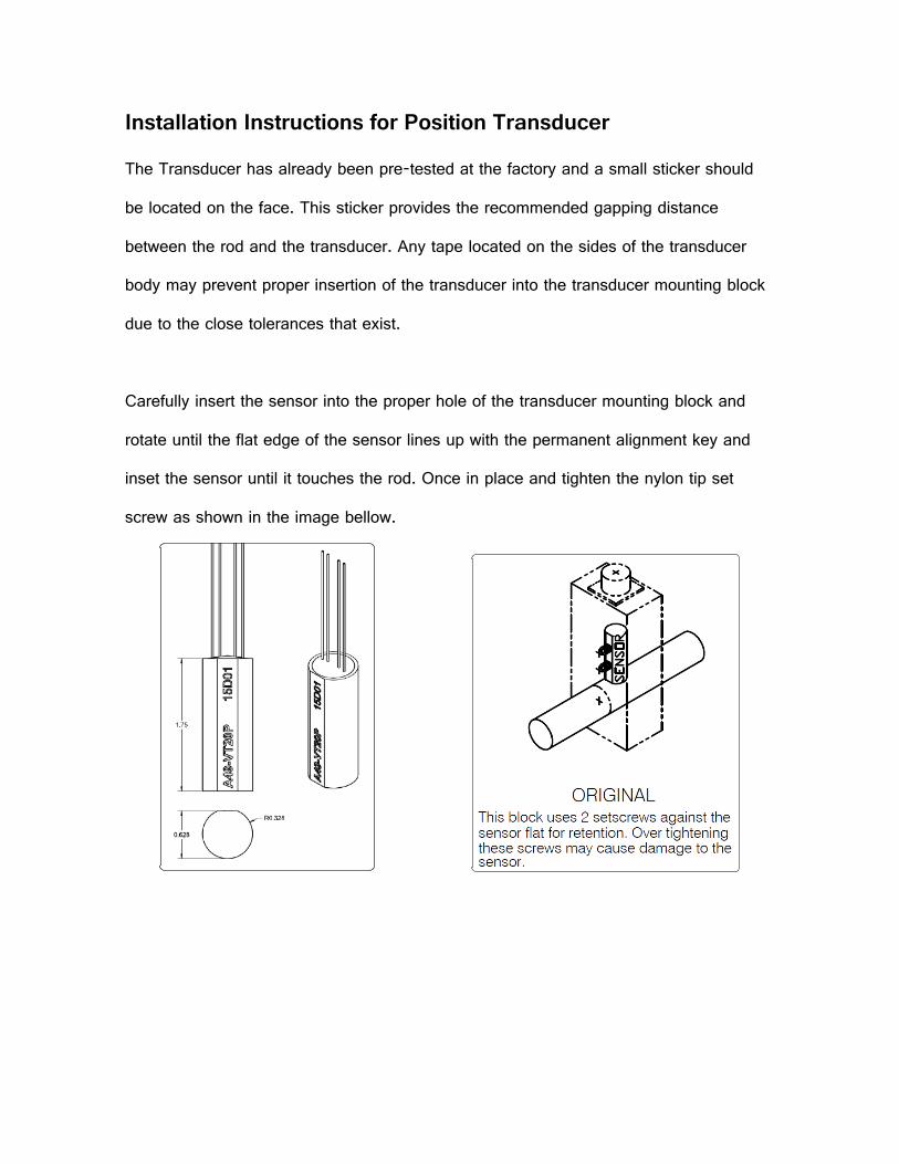
Installation Instructions for Position Transducer
The Transducer has already been pre-tested at the factory and a small sticker should
be located on the face. This sticker provides the recommended gapping distance
between the rod and the transducer. Any tape located on the sides of the transducer
body may prevent proper insertion of the transducer into the transducer mounting block
due to the close tolerances that exist.
Carefully insert the sensor into the proper hole of the transducer mounting block and
rotate until the flat edge of the sensor lines up with the permanent alignment key and
inset the sensor until it touches the rod. Once in place and tighten the nylon tip set
screw as shown in the image bellow.
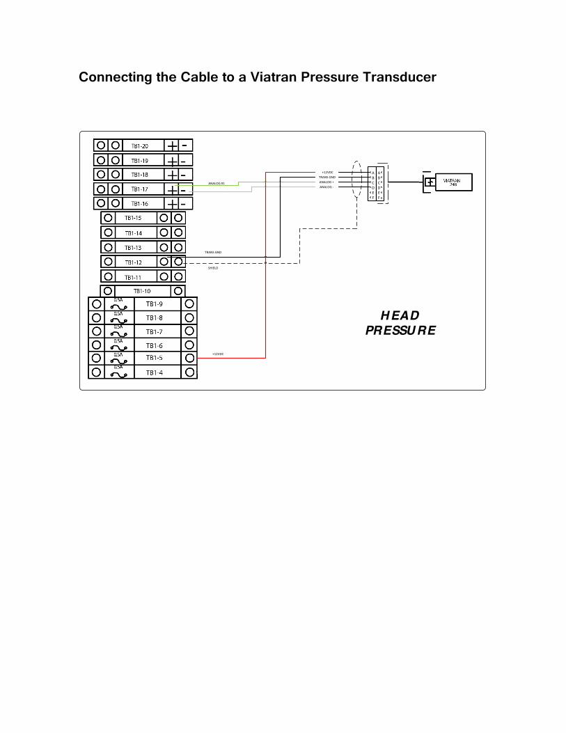
Connecting the Cable to a Viatran Pressure Transducer
ABCDEF
+12VDCTRANSGNDANALOG+ANALOG-
+12VDC
TRANSGND
SHIELD
ABCDEF
ANALOG#1
H EAD PRESSU RE
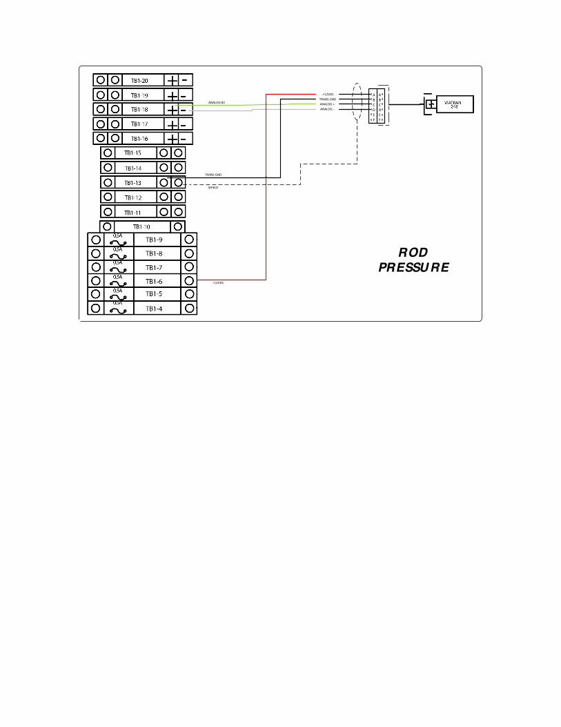
ABCDEF
+12VDCTRANSGNDANALOG+ANALOG-
+12VDC
TRANSGND
SHIELD
ABCDEF
ANALOG#2
RODPRESSURE
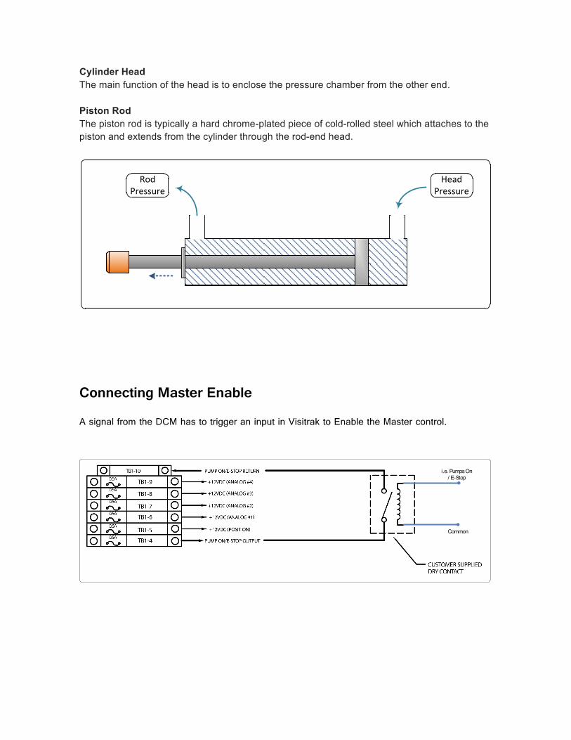
Cylinder Head The main function of the head is to enclose the pressure chamber from the other end. Piston Rod The piston rod is typically a hard chrome-plated piece of cold-rolled steel which attaches to the piston and extends from the cylinder through the rod-end head.
RodPressure
HeadPressure
Connecting Master Enable
A signal from the DCM has to trigger an input in Visitrak to Enable the Master control.
i.e. Pumps On / E-Stop
Common
Shot Control Wiring
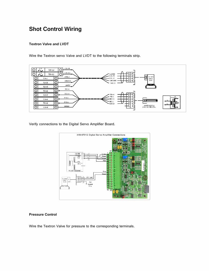
Textron Valve and LVDT
Wire the Textron servo Valve and LVDT to the following terminals strip.
Verify connections to the Digital Servo Amplifier Board.
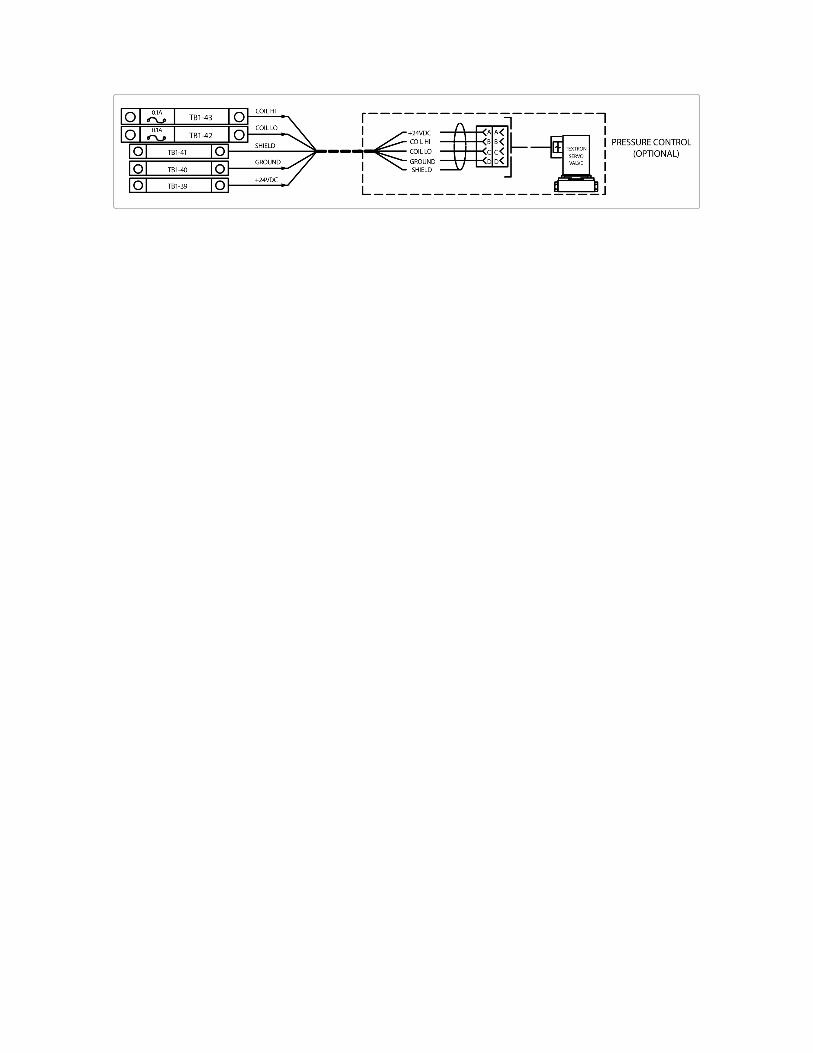
Pressure Control
Wire the Textron Valve for pressure to the corresponding terminals.
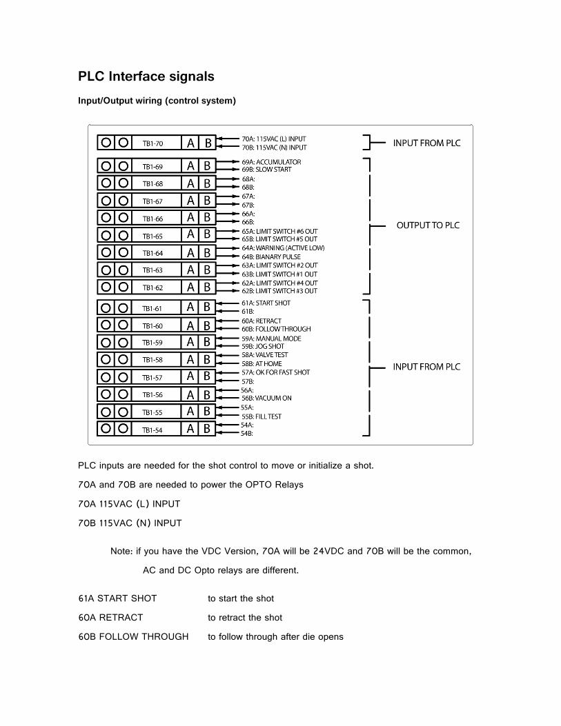
PLC Interface signals Input/Output wiring (control system)
PLC inputs are needed for the shot control to move or initialize a shot.
70A and 70B are needed to power the OPTO Relays
70A 115VAC (L) INPUT
70B 115VAC (N) INPUT
Note: if you have the VDC Version, 70A will be 24VDC and 70B will be the common,
AC and DC Opto relays are different.
61A START SHOT to start the shot
60A RETRACT to retract the shot
60B FOLLOW THROUGH to follow through after die opens

59A MANUAL MODE shot control is set to manual mode
59B JOG SHOT while in manual mode shot can be jogged
58B AT HOME limit switch that indicates that the shot is fully retracted
57A OK FOR FAST SHOT condition for vacuum indicating that the vacuum valve has closed
56B VACUUM ON turn vacuum ON

Sure-Trak2™ Control System
Calibration for Servo Valve (50mm, 80mm) w/ Digital Servo
Amp
Check for your pin connectors in your Servo Amp Board as the following image.
Go to the “Monitor” Menu, and select “FasTrak Board Monitor”.
Click on the “F2 Set Dac”, when the system asks to deactivate the control click “OK”.

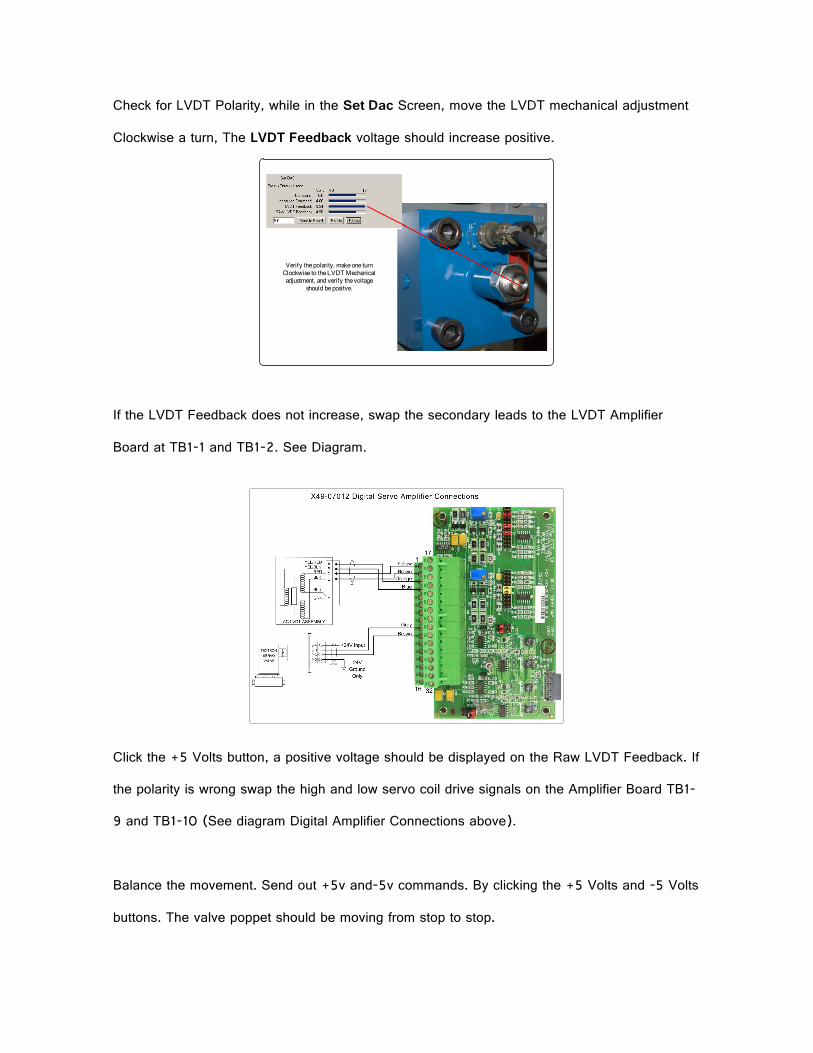
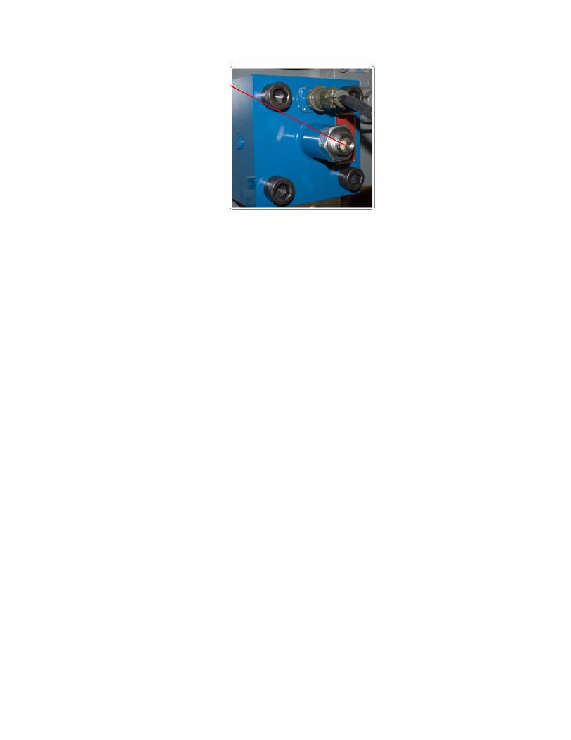
Check for LVDT Polarity, while in the Set Dac Screen, move the LVDT mechanical adjustment
Clockwise a turn, The LVDT Feedback voltage should increase positive.
Verify the polarity, make one turn Clockwise to the LVDT Mechanical adjustment, and verify the voltage
should be positve.
If the LVDT Feedback does not increase, swap the secondary leads to the LVDT Amplifier
Board at TB1-1 and TB1-2. See Diagram.
Click the +5 Volts button, a positive voltage should be displayed on the Raw LVDT Feedback. If
the polarity is wrong swap the high and low servo coil drive signals on the Amplifier Board TB1-
9 and TB1-10 (See diagram Digital Amplifier Connections above).
Balance the movement. Send out +5v and-5v commands. By clicking the +5 Volts and -5 Volts
buttons. The valve poppet should be moving from stop to stop.

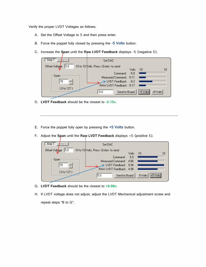
Verify the proper LVDT Voltages as follows:
A. Set the Offset Voltage to 5 and then press enter.
B. Force the poppet fully closed by pressing the -5 Volts button.
C. Increase the Span until the Raw LVDT Feedback displays -5 (negative 5).
D. LVDT Feedback should be the closest to -0.15v.
E. Force the poppet fully open by pressing the +5 Volts button.
F. Adjust the Span until the Raw LVDT Feedback displays +5 (positive 5).
G. LVDT Feedback should be the closest to +9.98v.
H. If LVDT voltage does not adjust, adjust the LVDT Mechanical adjustment screw and
repeat steps “B to G”.
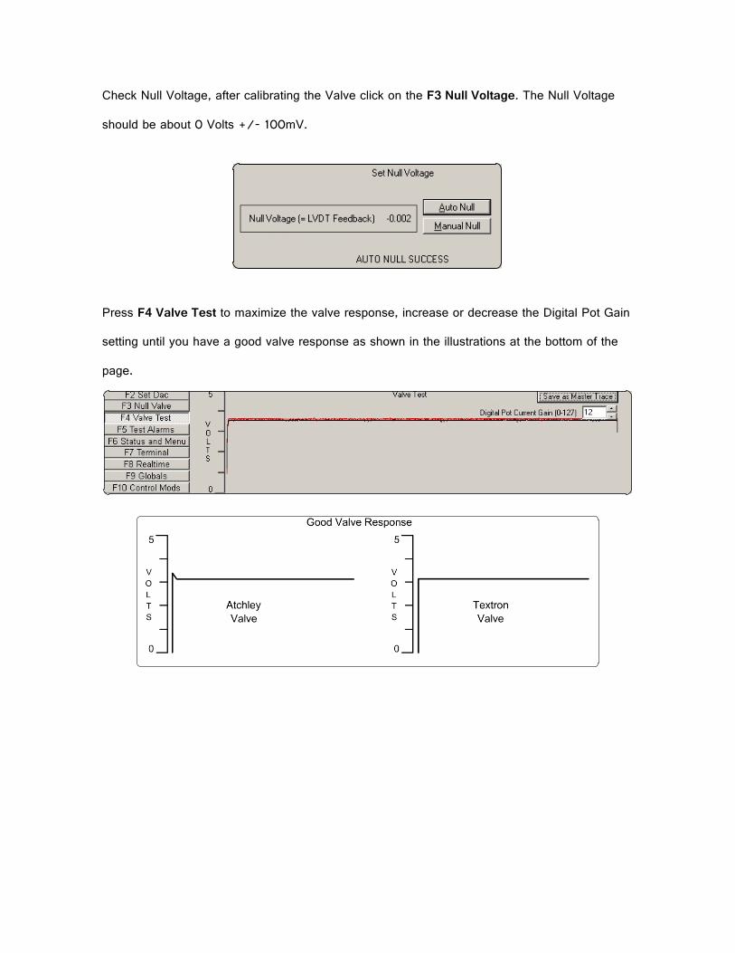
Check Null Voltage, after calibrating the Valve click on the F3 Null Voltage. The Null Voltage
should be about 0 Volts +/- 100mV.
Press F4 Valve Test to maximize the valve response, increase or decrease the Digital Pot Gain
setting until you have a good valve response as shown in the illustrations at the bottom of the
page.
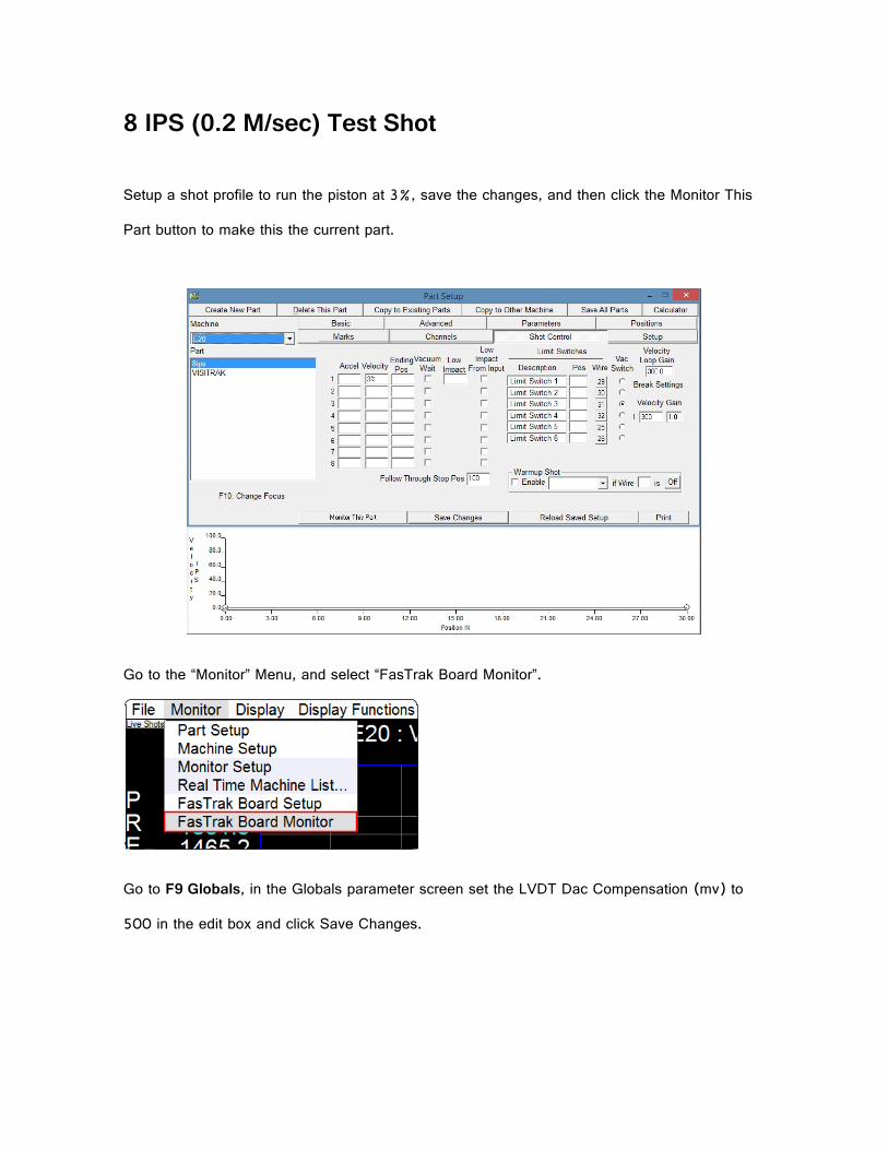
8 IPS (0.2 M/sec) Test Shot
Setup a shot profile to run the piston at 3%, save the changes, and then click the Monitor This
Part button to make this the current part.
Go to the “Monitor” Menu, and select “FasTrak Board Monitor”.
Go to F9 Globals, in the Globals parameter screen set the LVDT Dac Compensation (mv) to
500 in the edit box and click Save Changes.

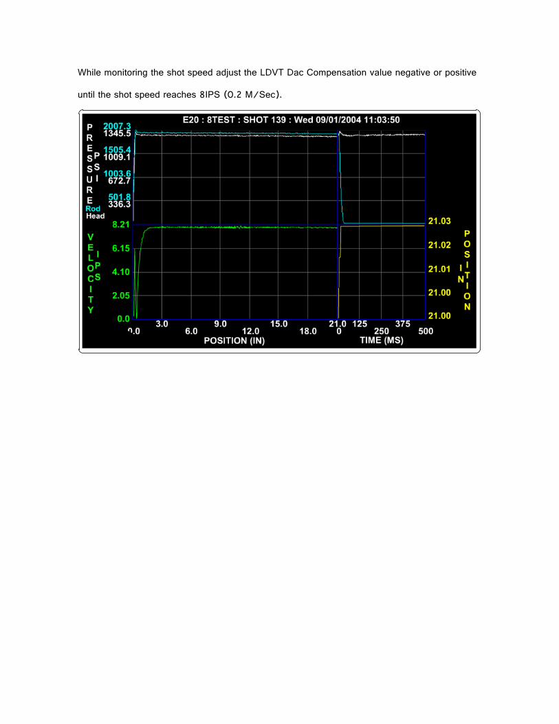
While monitoring the shot speed adjust the LDVT Dac Compensation value negative or positive
until the shot speed reaches 8IPS (0.2 M/Sec).