Embed Size (px)
Citation preview
©1996-2009 Operation Technology, Inc. – Workshop Notes: Short-Circuit IEC
Short-Circuit Analysis
IEC Standard
©1996-2009 Operation Technology, Inc. – Workshop Notes: Short-Circuit IEC Slide 2
Purpose of Short-Circuit
Studies
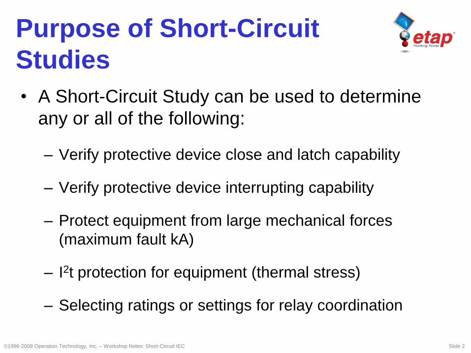
• A Short-Circuit Study can be used to determine
any or all of the following:
– Verify protective device close and latch capability
– Verify protective device interrupting capability
– Protect equipment from large mechanical forces
(maximum fault kA)
– I2t protection for equipment (thermal stress)
– Selecting ratings or settings for relay coordination
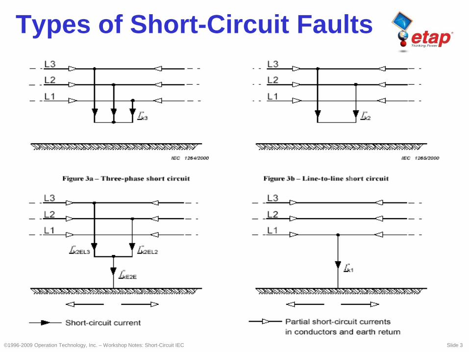
Types of Short-Circuit Faults
©1996-2009 Operation Technology, Inc. – Workshop Notes: Short-Circuit IEC Slide 3
©1996-2009 Operation Technology, Inc. – Workshop Notes: Short-Circuit IEC Slide 4
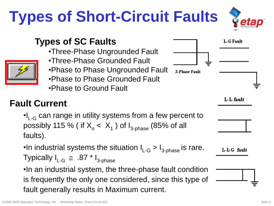
Types of SC Faults•Three-Phase Ungrounded Fault
•Three-Phase Grounded Fault
•Phase to Phase Ungrounded Fault
•Phase to Phase Grounded Fault
•Phase to Ground Fault
Fault Current
•IL-G can range in utility systems from a few percent to
possibly 115 % ( if Xo < X1 ) of I3-phase (85% of all
faults).
•In industrial systems the situation IL-G > I3-phase is rare.
Typically IL-G .87 * I3-phase
•In an industrial system, the three-phase fault condition
is frequently the only one considered, since this type of
fault generally results in Maximum current.
Types of Short-Circuit Faults
©1996-2009 Operation Technology, Inc. – Workshop Notes: Short-Circuit IEC Slide 5
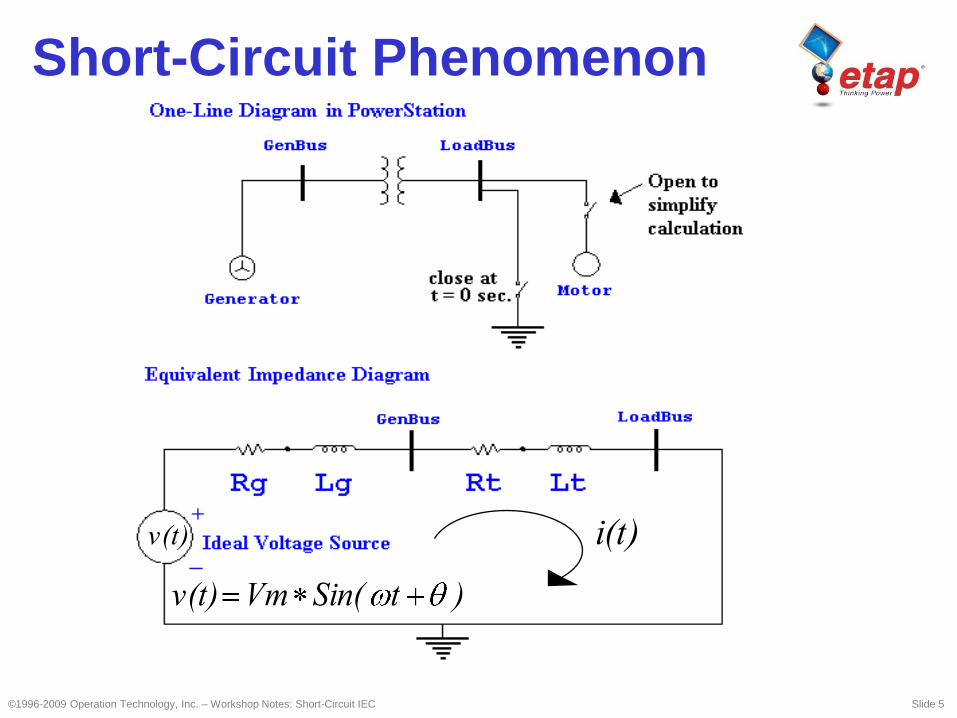
)tSin(Vmv(t)
i(t)v(t)
Short-Circuit Phenomenon
©1996-2009 Operation Technology, Inc. – Workshop Notes: Short-Circuit IEC Slide 6
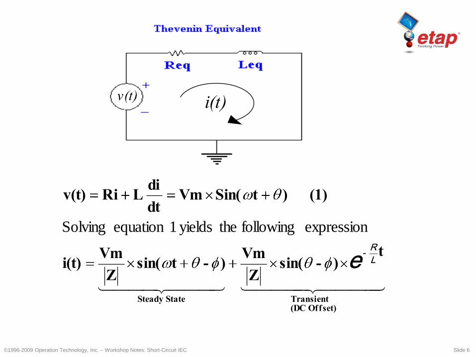
Offset) (DCTransientState Steady
t) - sin(
Z
Vm ) - tsin(
Z
Vmi(t)
(1) ) t Sin(Vmdt
di L Riv(t)
L
R-
e
expression following theyields 1equation Solving
i(t)v(t)

DC Current
AC Current (Symmetrical) with
No AC Decay
©1996-2009 Operation Technology, Inc. – Workshop Notes: Short-Circuit IEC Slide 7
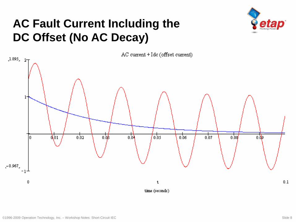
AC Fault Current Including the
DC Offset (No AC Decay)
©1996-2009 Operation Technology, Inc. – Workshop Notes: Short-Circuit IEC Slide 8
©1996-2009 Operation Technology, Inc. – Workshop Notes: Short-Circuit IEC Slide 9
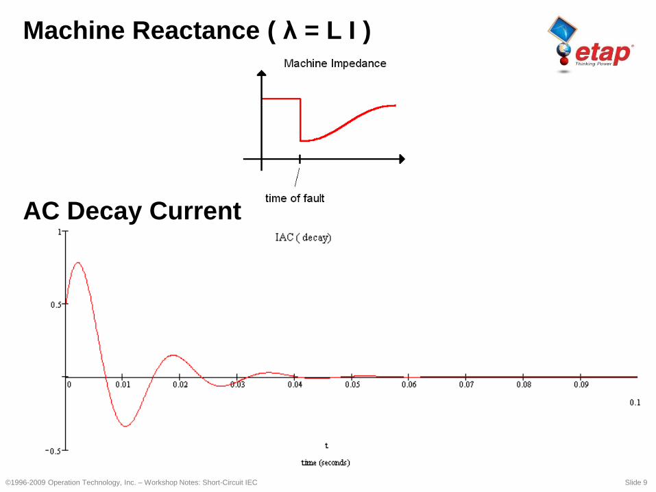
Machine Reactance ( λ = L I )
AC Decay Current
©1996-2009 Operation Technology, Inc. – Workshop Notes: Short-Circuit IEC Slide 10
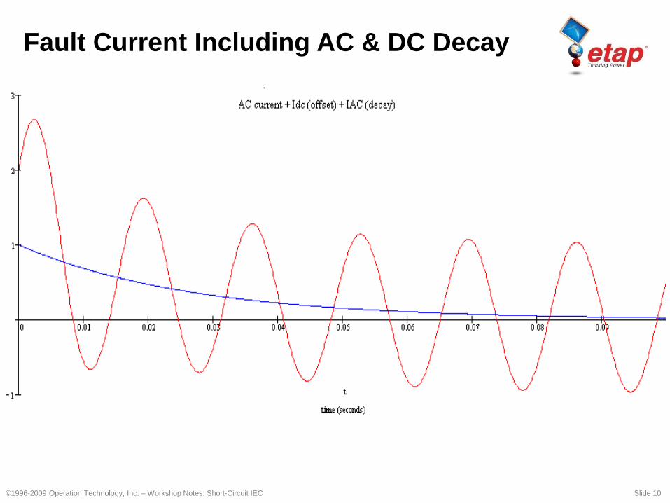
Fault Current Including AC & DC Decay
©1996-2009 Operation Technology, Inc. – Workshop Notes: Short-Circuit IEC Slide 11
IEC Short-Circuit
Calculation (IEC 909)
• Initial Symmetrical Short-Circuit Current (I"k)
• Peak Short-Circuit Current (ip)
• Symmetrical Short-Circuit Breaking Current
(Ib)
• Steady-State Short-Circuit Current (Ik)

©1996-2009 Operation Technology, Inc. – Workshop Notes: Short-Circuit IEC Slide 12
IEC Short-Circuit
Calculation Method
• Ik” = Equivalent V @ fault location divided by
equivalent Z
• Equivalent V is based bus nominal kV and c
factor
• XFMR and machine Z adjusted based on
cmax, component Z & operating conditions
©1996-2009 Operation Technology, Inc. – Workshop Notes: Short-Circuit IEC Slide 13
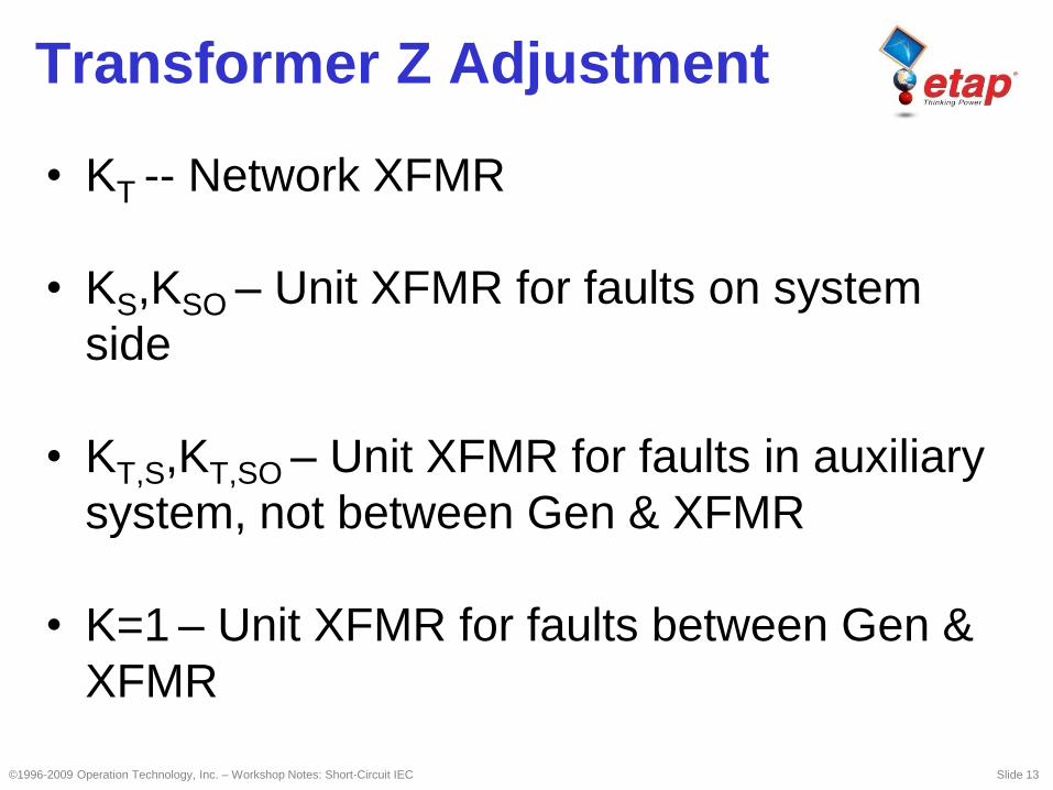
Transformer Z Adjustment
• KT -- Network XFMR
• KS,KSO – Unit XFMR for faults on system
side
• KT,S,KT,SO – Unit XFMR for faults in auxiliary
system, not between Gen & XFMR
• K=1 – Unit XFMR for faults between Gen &
XFMR
©1996-2009 Operation Technology, Inc. – Workshop Notes: Short-Circuit IEC Slide 14
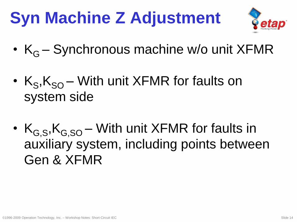
Syn Machine Z Adjustment
• KG – Synchronous machine w/o unit XFMR
• KS,KSO – With unit XFMR for faults on
system side
• KG,S,KG,SO – With unit XFMR for faults in
auxiliary system, including points between
Gen & XFMR
©1996-2009 Operation Technology, Inc. – Workshop Notes: Short-Circuit IEC Slide 15
Types of Short-Circuits
• Near-To-Generator Short-Circuit
– This is a short-circuit condition to which at least
one synchronous machine contributes a
prospective initial short-circuit current which is
more than twice the generator’s rated current, or
a short-circuit condition to which synchronous
and asynchronous motors contribute more than
5% of the initial symmetrical short-circuit current
( I"k) without motors.
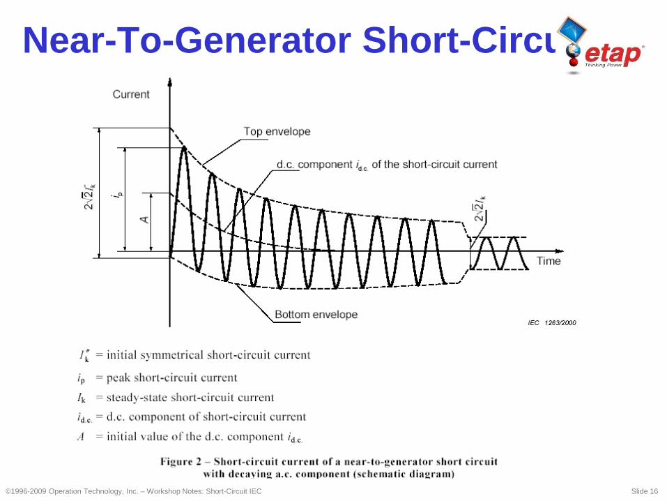
Near-To-Generator Short-Circuit
©1996-2009 Operation Technology, Inc. – Workshop Notes: Short-Circuit IEC Slide 16
©1996-2009 Operation Technology, Inc. – Workshop Notes: Short-Circuit IEC Slide 17
Types of Short-Circuits
• Far-From-Generator Short-Circuit
– This is a short-circuit condition during which the
magnitude of the symmetrical ac component of
available short-circuit current remains essentially
constant.
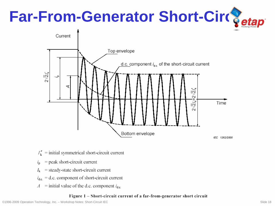
Far-From-Generator Short-Circuit
©1996-2009 Operation Technology, Inc. – Workshop Notes: Short-Circuit IEC Slide 18
©1996-2009 Operation Technology, Inc. – Workshop Notes: Short-Circuit IEC Slide 19
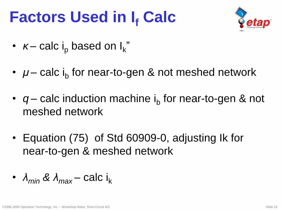
Factors Used in If Calc
• κ – calc ip based on Ik”
• μ – calc ib for near-to-gen & not meshed network
• q – calc induction machine ib for near-to-gen & not
meshed network
• Equation (75) of Std 60909-0, adjusting Ik for
near-to-gen & meshed network
• λmin & λmax – calc ik
©1996-2009 Operation Technology, Inc. – Workshop Notes: Short-Circuit IEC Slide 20
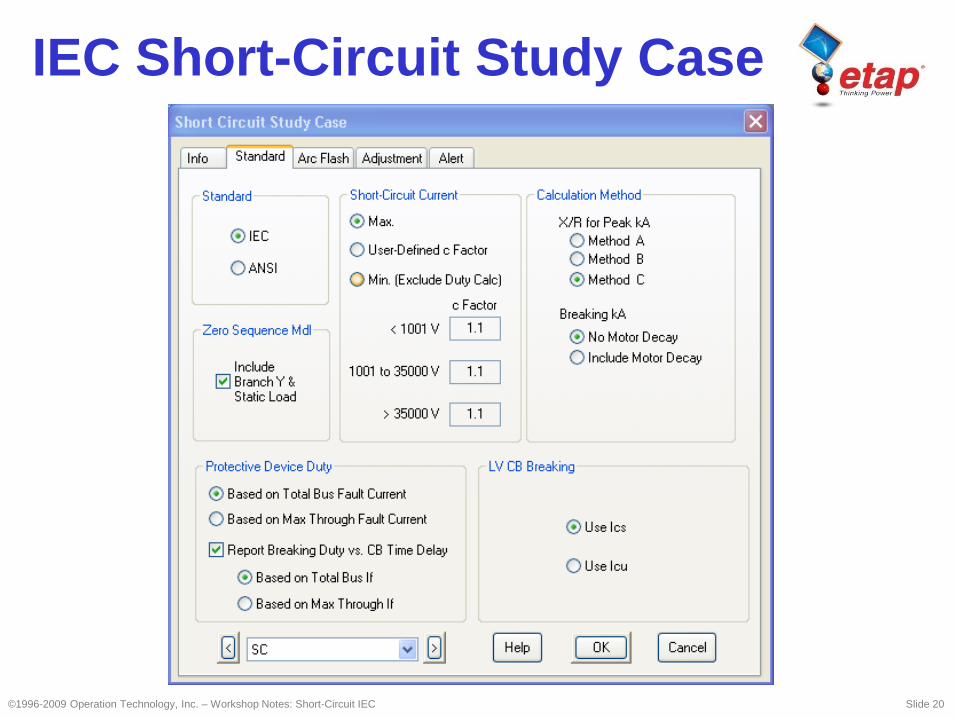
IEC Short-Circuit Study Case

©1996-2009 Operation Technology, Inc. – Workshop Notes: Short-Circuit IEC Slide 21
Types of Short-Circuits
• Maximum voltage factor is used
• Minimum impedance is used (all negative
tolerances are applied and minimum
resistance temperature is considered)
When these options
are selected

©1996-2009 Operation Technology, Inc. – Workshop Notes: Short-Circuit IEC Slide 22
Types of Short-Circuits
• Minimum voltage factor is used
• Maximum impedance is used (all positive
tolerances are applied and maximum
resistance temperature is considered)
When this option is
selected
©1996-2009 Operation Technology, Inc. – Workshop Notes: Short-Circuit IEC Slide 23
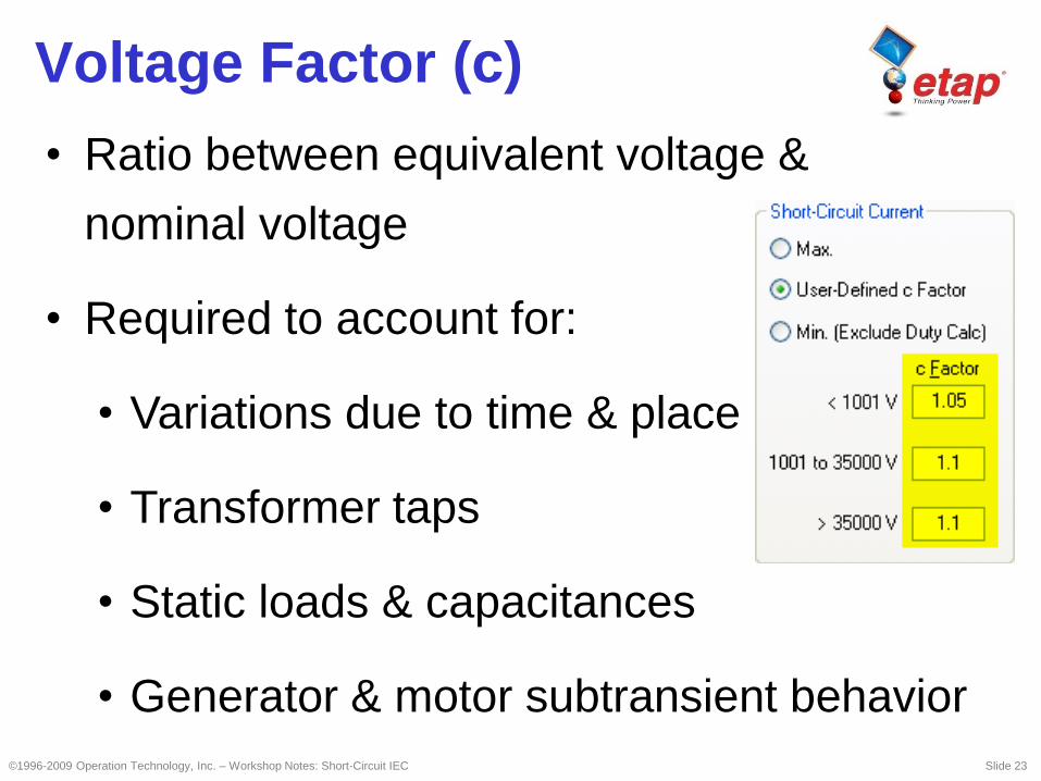
Voltage Factor (c)
• Ratio between equivalent voltage &
nominal voltage
• Required to account for:
• Variations due to time & place
• Transformer taps
• Static loads & capacitances
• Generator & motor subtransient behavior
©1996-2009 Operation Technology, Inc. – Workshop Notes: Short-Circuit IEC Slide 24
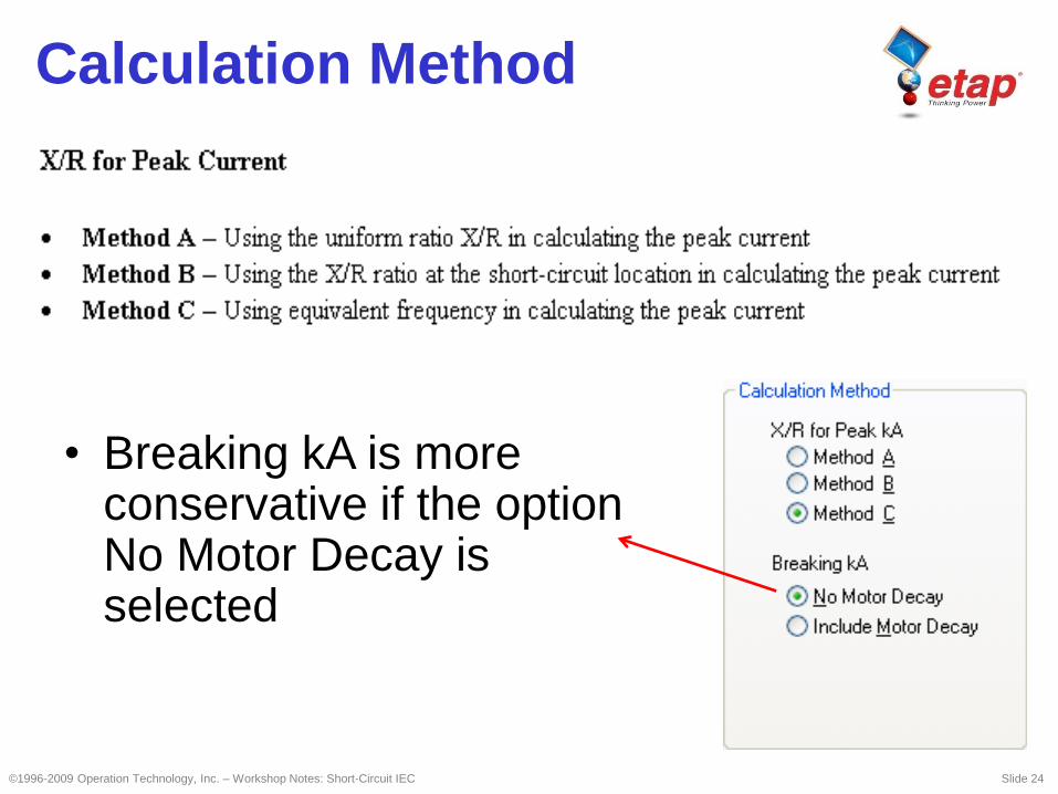
Calculation Method
• Breaking kA is more conservative if the option No Motor Decay is selected
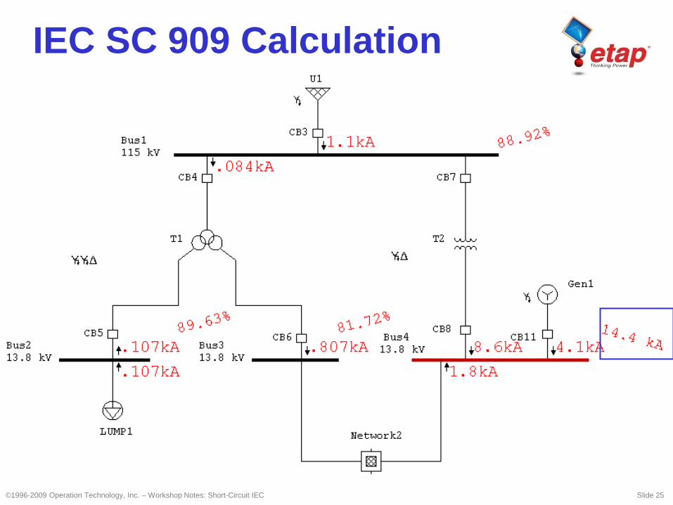
IEC SC 909 Calculation
©1996-2009 Operation Technology, Inc. – Workshop Notes: Short-Circuit IEC Slide 25
©1996-2009 Operation Technology, Inc. – Workshop Notes: Short-Circuit IEC Slide 26
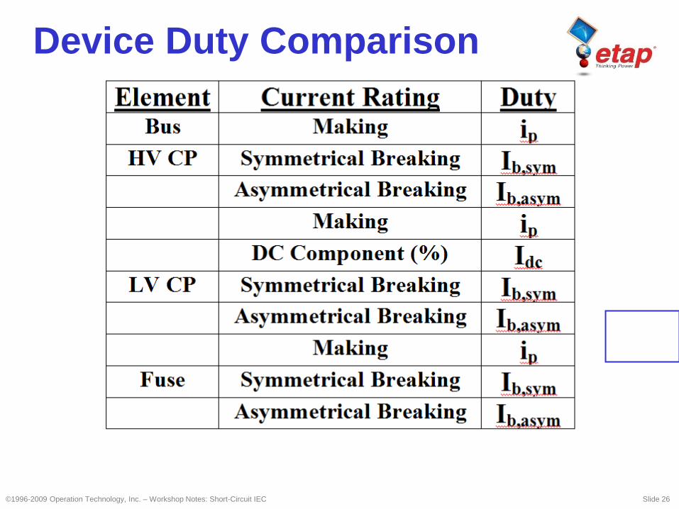
Device Duty Comparison
©1996-2009 Operation Technology, Inc. – Workshop Notes: Short-Circuit IEC Slide 27
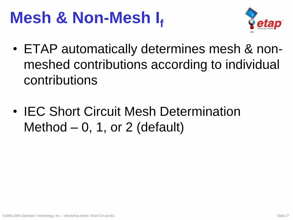
Mesh & Non-Mesh If
• ETAP automatically determines mesh & non-
meshed contributions according to individual
contributions
• IEC Short Circuit Mesh Determination
Method – 0, 1, or 2 (default)
©1996-2009 Operation Technology, Inc. – Workshop Notes: Short-Circuit IEC Slide 28
L-G Faults

©1996-2009 Operation Technology, Inc. – Workshop Notes: Short-Circuit IEC Slide 29
Symmetrical Components
L-G Faults

©1996-2009 Operation Technology, Inc. – Workshop Notes: Short-Circuit IEC Slide 30
Sequence Networks
©1996-2009 Operation Technology, Inc. – Workshop Notes: Short-Circuit IEC Slide 31
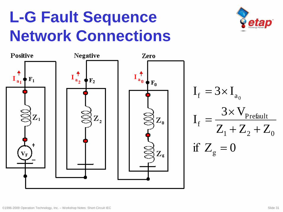
0
ZZZ
V3I
I3I
021
efaultPrf
af 0
g Zif
L-G Fault Sequence
Network Connections
©1996-2009 Operation Technology, Inc. – Workshop Notes: Short-Circuit IEC Slide 32
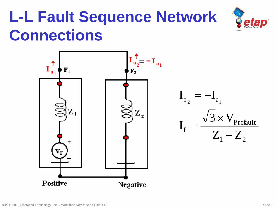
21
efaultPrf
aa
ZZ
V3I
II12
L-L Fault Sequence Network
Connections
©1996-2009 Operation Technology, Inc. – Workshop Notes: Short-Circuit IEC Slide 33
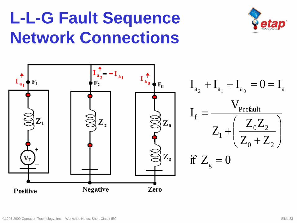
0
ZZ
ZZZ
VI
I0III
20
201
efaultPrf
aaaa 012
g Zif
L-L-G Fault Sequence
Network Connections
©1996-2009 Operation Technology, Inc. – Workshop Notes: Short-Circuit IEC Slide 34
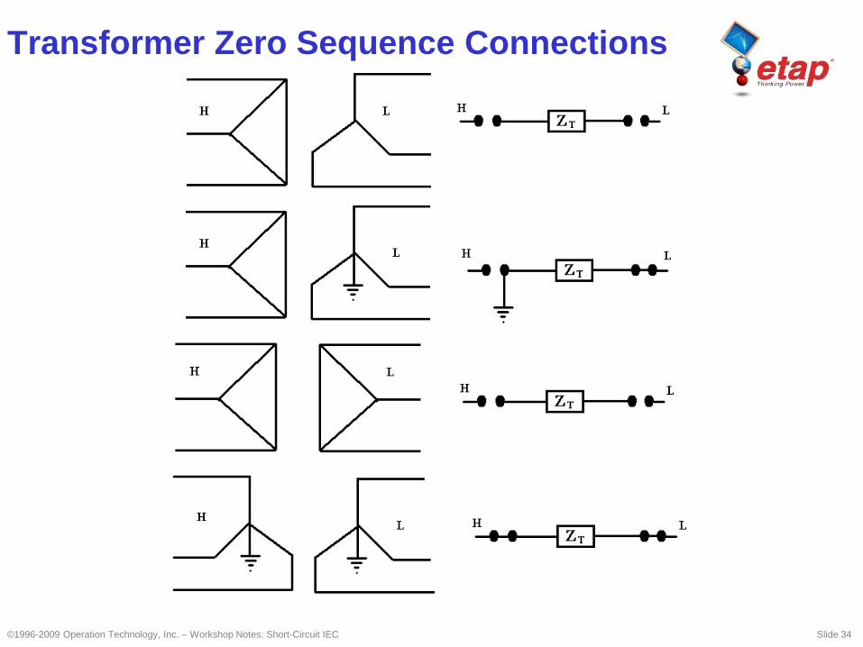
Transformer Zero Sequence Connections
©1996-2009 Operation Technology, Inc. – Workshop Notes: Short-Circuit IEC Slide 35
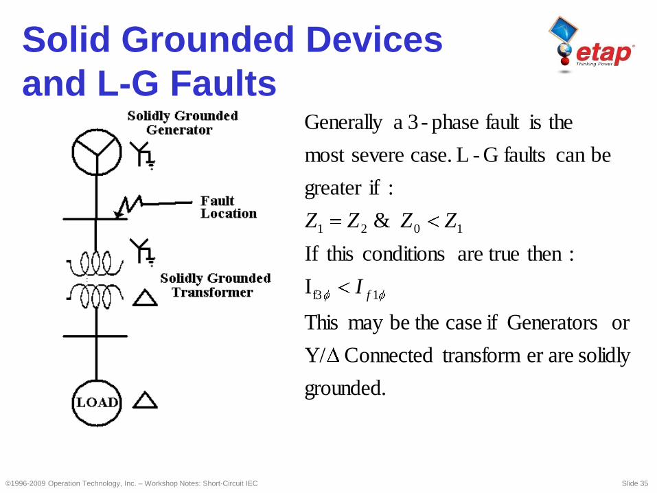
grounded.
solidly areer transformConnected Y/
or Generators if case thebemay This
I
: then trueare conditions thisIf
&
: ifgreater
becan faultsG -L case. severemost
theisfault phase-3 aGenerally
1f3
1021
fI
ZZZZ
Solid Grounded Devices
and L-G Faults
©1996-2009 Operation Technology, Inc. – Workshop Notes: Short-Circuit IEC Slide 36
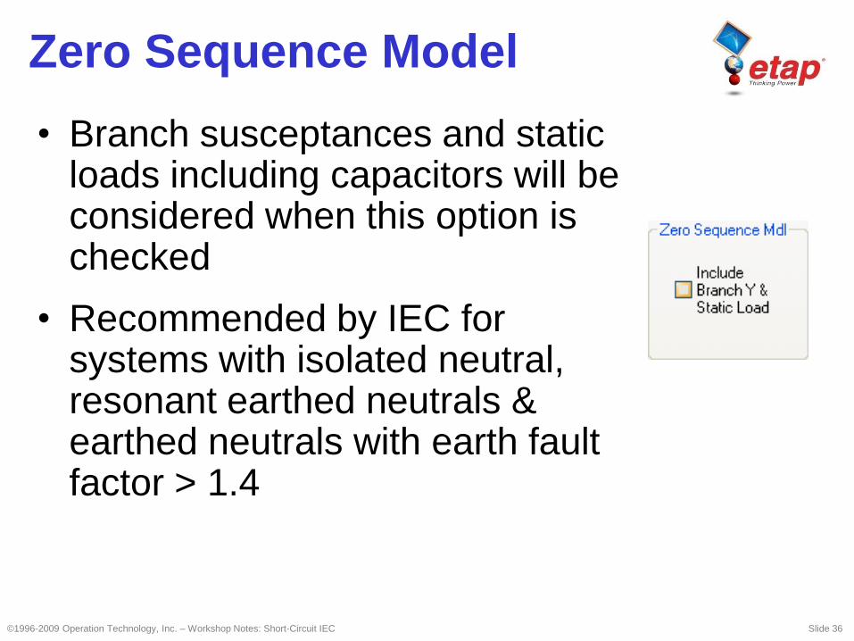
Zero Sequence Model
• Branch susceptances and static loads including capacitors will be considered when this option is checked
• Recommended by IEC for systems with isolated neutral, resonant earthed neutrals & earthed neutrals with earth fault factor > 1.4
©1996-2009 Operation Technology, Inc. – Workshop Notes: Short-Circuit IEC Slide 37
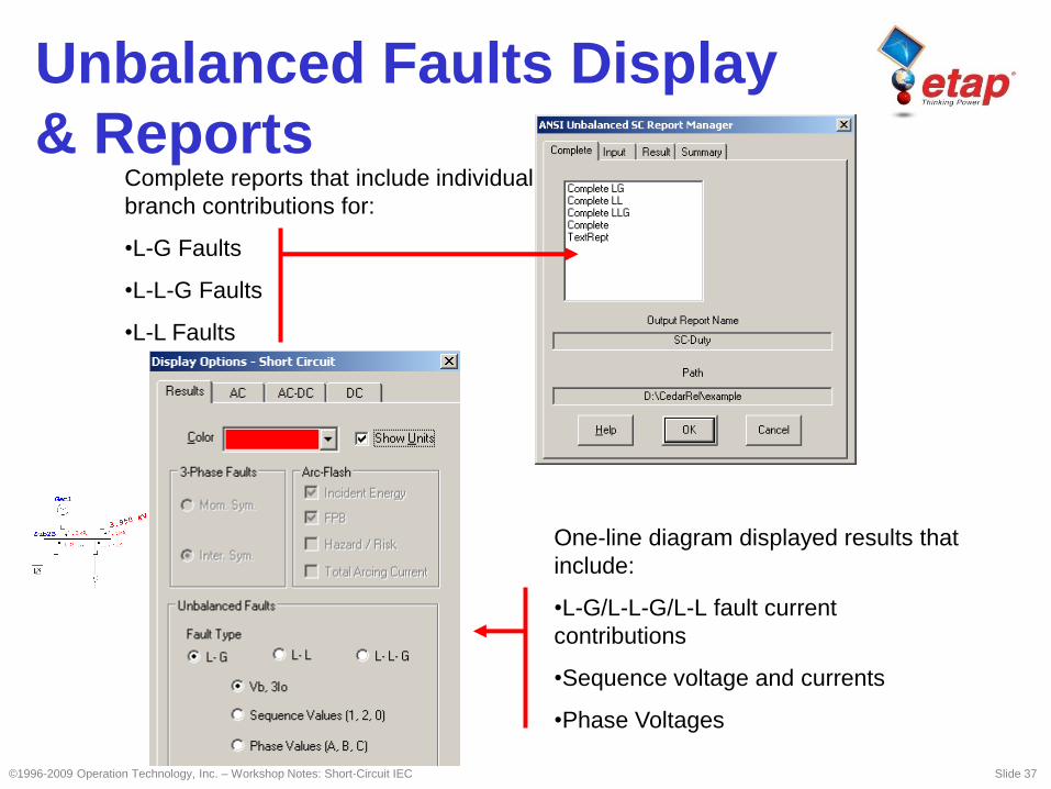
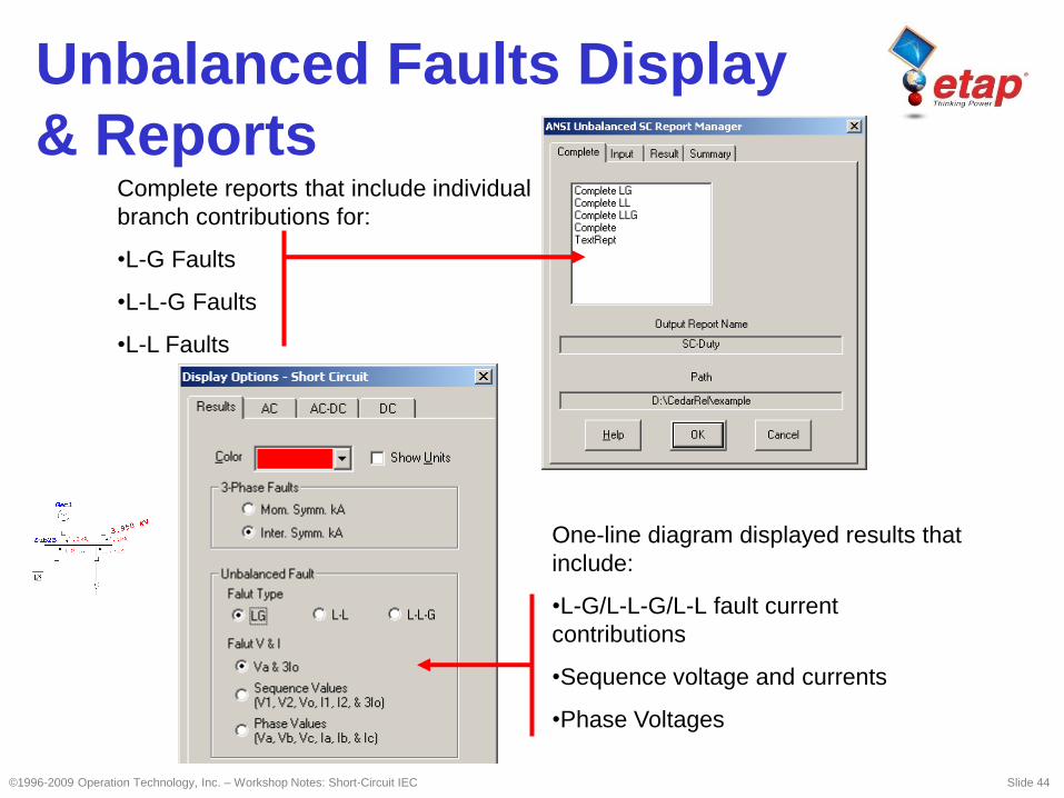
Complete reports that include individual
branch contributions for:
•L-G Faults
•L-L-G Faults
•L-L Faults
One-line diagram displayed results that
include:
•L-G/L-L-G/L-L fault current
contributions
•Sequence voltage and currents
•Phase Voltages
Unbalanced Faults Display
& Reports

©1996-2009 Operation Technology, Inc. – Workshop Notes: Short-Circuit IEC Slide 38
Total Fault Current Waveform
Transient Fault Current
Calculation (IEC 61363)
©1996-2009 Operation Technology, Inc. – Workshop Notes: Short-Circuit IEC Slide 39
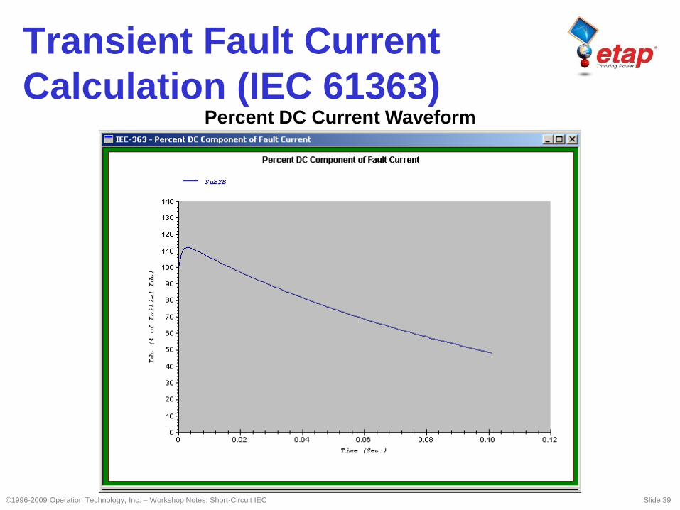
Percent DC Current Waveform
Transient Fault Current
Calculation (IEC 61363)
©1996-2009 Operation Technology, Inc. – Workshop Notes: Short-Circuit IEC Slide 40
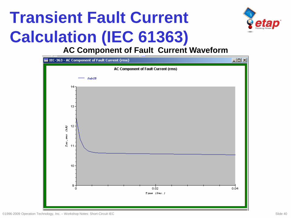
AC Component of Fault Current Waveform
Transient Fault Current
Calculation (IEC 61363)
©1996-2009 Operation Technology, Inc. – Workshop Notes: Short-Circuit IEC Slide 41
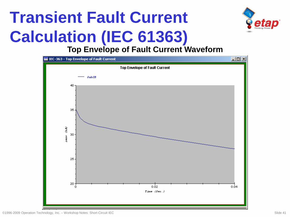
Top Envelope of Fault Current Waveform
Transient Fault Current
Calculation (IEC 61363)
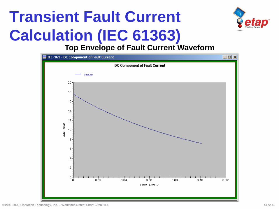
©1996-2009 Operation Technology, Inc. – Workshop Notes: Short-Circuit IEC Slide 42
Top Envelope of Fault Current Waveform
Transient Fault Current
Calculation (IEC 61363)
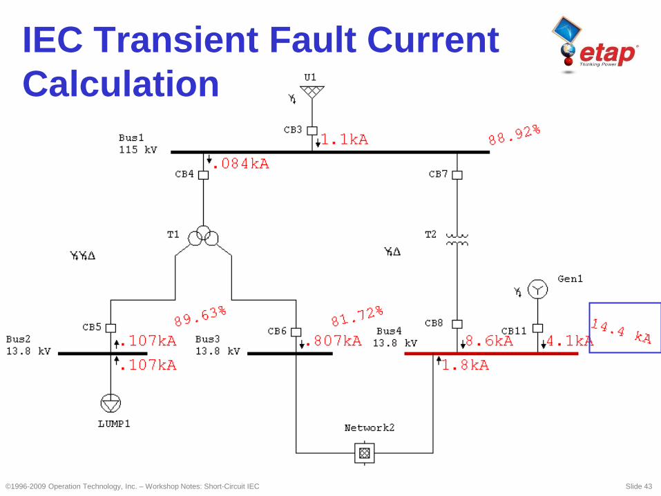
IEC Transient Fault Current
Calculation
©1996-2009 Operation Technology, Inc. – Workshop Notes: Short-Circuit IEC Slide 43
©1996-2009 Operation Technology, Inc. – Workshop Notes: Short-Circuit IEC Slide 44
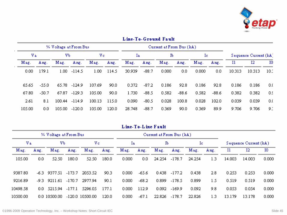
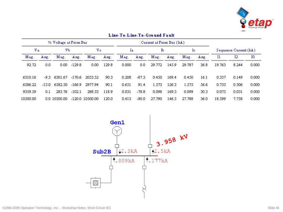
Complete reports that include individual
branch contributions for:
•L-G Faults
•L-L-G Faults
•L-L Faults
One-line diagram displayed results that
include:
•L-G/L-L-G/L-L fault current
contributions
•Sequence voltage and currents
•Phase Voltages
Unbalanced Faults Display
& Reports
©1996-2009 Operation Technology, Inc. – Workshop Notes: Short-Circuit IEC Slide 45
©1996-2009 Operation Technology, Inc. – Workshop Notes: Short-Circuit IEC Slide 46