Embed Size (px)
Citation preview

An Instron Company
Durometers


Shore® Durometers
p3 p4
p12
p6
p13
p8
p14
p10
p15
Durometer Scale Selection Guide
S1 DigitalDurometers
Round Style Durometers
Test Blocks and Kits
Manual Stands for Round and Digital Durometers
Resiliometers
Automatic Operating Stands
Shore Calibration and Repair Services
p11
Type M Systems Testing Tips

2
For hardness testing of elastomers and plastics, Shore® durometers are ideal. Shore durometers conform to allASTM and international standards and are easy-to-use. This brochure contains durometers and durometer systems that cover the entire spectrum of indentation hardness testing of rubber-like materials. Each durometer type is made to a specifi c scale (i.e. A,B,C,D) and is capable of producing a value between 0 and 100. For M scale testing, Shore manufactures the micro system, which is designed to determine the hardness of soft elastomers too thin or too irregularly shaped, such as small o-rings, for measurement with macro durometers. All durometers except for the M scale units can be used as a portable device. Test stands are recommended for best accuracy and are required for M scale testing due to its increased sensitivity.
Shore Test Method
The Shore test uses a hardened indenter, an accurately calibrated spring, a depth indicator, and a fl at presser foot. The indenter protrudes from the middle of the presser foot and extends 2.5 mm from the surface of the foot. In the fully extended position the indicator displays zero. When the indenter is depressed fl at even with the presser foot’s surface, the indicator displays 100. Therefore, every Shore point is equal to 0.0025 mm penetration (M scale is 0.00125 mm). To perform a test, the unit is placed on the sample so that the presser foot is held fi rmly against the test surface. The spring pushes the indenter into the sample and the indicator displays the depth of penetration. The deeper the indentation, the softer the material and the lower the indicator reading. The Shore A and D scales are by far the most commonly used. The M scale uses a very low force spring and was developed to allow testing very small parts like o-rings that cannot be tested in the normal A scale. Because different materials respond to the test scales in different ways, there is no correlation between the different scales. Shore test methods are defi ned in the following standards: ASTM D 2240, DIN 53 505, ISO 7619 Part 1, JIS K 6253, ASKER, C-SRIS-010 1 (now obsolete) Please consult factory for availability of Shore durometer for ASKER C testing.
Application
If you are not sure which durometer is right for your testing requirement, please contact us and we will gladly assist with your selection. Shore Instruments has been manufacturing durometers and solving customers’ rubber hardness testing issues for more than 80 years. You can speak with one of our Shore Instruments’ representatives for testing advice to address challenges resulting from the latest advances in industry and technology.
Calibration
A NVLAP® accredited calibration certifi cate is included with every new durometer. Annual recalibrations are recommended. Shore offers a full line of calibration and repair services. Please refer to the calibration sectionon page 14 for complete details.
Indenter Geometry
Frustum Cone
Introduction

3
The durometer selection guide will help you select the appropriate Shore hardnesstester for your application. The combinationof spring force and indenter geometry perASTM D 2240 (as defi ned by ASTM DIN 53505, ISO 7619-1 and ASTM D 2240) determines the type of durometer required for a particular application. There is not one type of durometer that can cover the entire hardness spectrum. When selecting a durometer it is important to take the readings into consideration (readings below 10 or above 90 are not considered reliable). In such cases the next appropriate scale should be chosen.
All Shore Durometers are compliant to ASTM D2240. The Shore S1 Digital Durometers meet or exceed ASTM D2240, DIN53505, and JIS K 6253.
Durometer Scale Selection Guide
Scale of Material To Be Used Catalog Number Model MaximumForce Indenter
A
Rubber: soft vulcanized (ie tire), natural nitrile.Elastomeric Materials (rubber and rubber-like):GR-S, GR-1, neopene, thiokol, fl exible polyacrylicesters. Other: wax, felt, leather, etc. (materials thatnormally yield under fi ngernail pressure such as theheel on your shoe).
9130-021407030000407040000407041000407141100407041400
S1-AXA
XAMXXACL
XACLMXXAMXHAF
821 g
Frustum cone
BRubber: moderately hard (ie typewriter rollers,platens, etc.).
9130-022407030100407041500
S1-BXB
XBHAF821 g
Sharp 30° angle
CRubber: medium hardPlastics: medium hard
9130-023407030200407040200407042000
S1-CXC
XCMXXCHAF
4533 g
Frustum cone
D
Rubber, Hard Plastics: harder grades such as rigid thermoplastics, plexiglas, thermopolystyrene, vinyl,sheet, cellulode acetate, thermosetting laminates (ie formica) Other: paper-fi lled calendar rolls, calendar bowls, etc. (materials that would not normally indent under fi ngernail pressure, such as a pocket comb).
9130-024407030300407040300407041900407042000
S1-DXD
XDMXXDHAF
XDMXHAF
4533 g
Sharp 30° angle
DO Textile Windings: very dense, slasher beams, etc.
9130-025407030400407040400407042100
S1-DOXDO
XDOMXXDOHAF
4533 g
0.0468 radius
E Soft rubber, sponges and foams9130-0579130-058
XEXEMX
821 g
0.0980 radius
ORubber: soft (ie soft printer rolls, artgum)Textile Windings: medium density(ie rayon, orlon, nylon)
9130-026407030500407040500407042300
S1-OXO
XOMXXOHAF
821 g
0.0468 radius
OOTextile Windings: low densityOther: sponge rubber and plastics (not for useon foamed latex)
9130-027407030600407042500
S1-OOXOO
XOOHAF113 g
0.0468 radius
OOO-S Plastic Foams: suit foams, open or closed cells 407030800 X000-S 197 g
0.420 radius
MRubber: o-rings and thin sheet min 1.25 mm(0.05 in) thick. Complete with stand.
9130-032407140000
719/S1 DIG714/ ANALOG
78 g
Sharp 30° angle

4
Why Modular Design?
Modular design allows for quick scale changes, just snap in one of eight precalibrated probes.
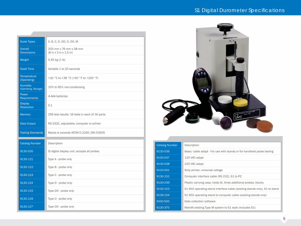
The Shore® model S1 portable digital durometer is a handheld hardness tester especially designed for rubber and other elastomeric materials. The instrument is housed in black polypropylene that is shaped to fi t comfortably in the hand. The tester has a calibrated spring to create a known load on the indenter. Hardness is measured by determining the depth of penetration of the indenter, relative to the presser foot, into the material being tested. The measurement displays on a high-contrast LCD, which also displays test parameters, set-up, tester functions, specimen and sample information. The user-friendly design features a six-button control panel, sound transducer, RS232 serial port, statistical capabilities, and memory for up to 256 test results.
Principle of Operation The tester unit has a detachable probe that contains an indenter and calibrated spring suitable for the various durometer scales. The probe also contains circuitry that lets the main durometer unit automatically recognize it. This gives the operator the ability to interchange probes for different durometer scales using one durometer head. The probe is factory calibrated and does not need any further calibration upon delivery.
Features• High contrast LCD display with backlighting and large easy-to read numbers• Test counter automatically counts the number of tests and number of parts • Ergonomically-designed• Ability to quickly switch scales by changing precalibrated probes• Statistics, including average or median result options, and minimum and maximum tolerance settings • Automatic sleep mode for long battery life, low battery indicator• Optional AC adapter available• Meets or exceeds ASTM D 2240, DIN 53505, JIS K 6253• Fits all existing Shore stands with optional base and cable adapter (Excluding Type M).
Description Description9130-021 Type A full unit - A probe and head unit S1 A
9130-024 Type D full unit - D probe and head unit S1 D
9130-032 Type M - micro system includes stand S1–719
S1 Digital Durometer
5
Scale Types A, B, C, D, DO, O, OO, M
Overall Dimensions
203 mm x 76 mm x 38 mm(8 in x 3 in x 1.5 in)
Weight 0.45 kg (1 lb)
Dwell Time Variable 1 to 25 seconds
Temperature (Operating)
+10 °C to +38 °C (+50 °F to +100 °F)
Humidity (Operating, Storage)
10% to 90% non-condensing
Power Requirements
4-AAA batteries
Display Resolution
0.1
Memory 256 test results: 16 tests in each of 16 parts
Data Output RS-232C, adjustable; computer or printer
Testing Standards Meets or exceeds ASTM D 2240, DIN 53505
Catalog Number Description
9130-035 SI digital display unit, accepts all probes
9130-121 Type A - probe only
9130-122 Type B - probe only
9130-123 Type C - probe only
9130-124 Type D - probe only
9130-125 Type DO - probe only
9130-126 Type O - probe only
9130-127 Type OO - probe only
Catalog Number Description
9130-036 Base/ cable adapt - For use with stands or for handheld probe testing
9130-037 120 VAC adapt
9130-038 220 VAC adapt
9120-501 Strip printer, universal voltage
9130-152 Computer interface cable (RS 232), S1 to PC
9130-039 Plastic carrying case, holds SI, three additional probes, blocks
9130-153 S1 902 operating stand interface cable (existing stands only), S1 to stand
9139-154 S1 902 operating stand to computer cable (existing stands only)
9100-500 Data collection software
9130-370 Retrofi t existing Type M system to S1 style (includes S1)
S1 Digital Durometer Specifi cations

6
Round Style Durometers
What is the difference between OOO or OOO-S?There are currently two types of OOO durometers that comply with ASTM D 2240 now recognized in the industry. In 2003, ASTM D 2240 designated the most widely used Shore Instruments version, as the OOO-S in order to differentiate Shore from OOO scale durometers manufactured by other suppliers. The two distinct OOO units differ in indenter geometry and extension as well as spring force calibration. ASTM D 2240 recognizes both variations of the OOO and refers to the OOO-S as a Shore Instruments manufactured device.

7
Round Style Durometers
Round Style Durometers
The Shore® round style durometer was introduced in 1944. It is a general purpose device that is the most widely used instrument for the hardness testing of cellular, soft and hard rubber-like and plastic material. It is small enough to be carried in the pocket and rugged enough to operate in the most hostile environments. The round style durometer was designed to satisfy the industries’ needs for a unit with a scale graduated in increments of one rather than fi ve with a resolution of one durometer point. The analog durometer may be manually applied or, for better repeatability and accuracy, mounted on a compatible operating stand.
Principle of OperationShore analog durometers employ a calibrated spring that generates a known preload on the indenter. The durometer measures hardness by determining the depth of penetration into the material under test. The dial is graduated from 0-100 with a pointer sweep of 265 degrees.
Features• Rugged aluminum housing and movement frame, stainless steel precision compression main spring• Indenter guard and a glass lens that resist scratching and discoloration• Vinyl covered steel carrying case and test block are included• NVLAP® accredited certifi cate of calibration• Available Styles: standard, maximum hands, half inch foot and constant load durometers• Fits all existing Shore stands
ModelStandard and Maximum
Hand Durometers Constant Load DurometersHalf inch footDurometers
Scale Types All All All
Display Body Diameter67.3 mm(2.65 in)
67.3 mm(2.65 in)
67.3 mm(2.65 in)
Display Body Thickness28.4 mm(1.12 in)
28.4 mm(1.12 in)
28.4 mm(1.12 in)
Overall Length86.9 mm(3.42 in)
90.2 mm(3.55 in)
97 mm(3.82 in)
Presser Foot Dimension35 mm x 19 mm(1.4 in x 0.75 in)
51 mm x 51 mm(2 in x 2 in)
12.77 mm(0.5 in)
Weight220 g
(0.5 lb)1080 g(2.4 lb)
220 g(0.5 lb)

DR DRCL CV LRCatalog Number 407110000 407110100 407120000 407130000
Compatible Durometer
A, B, C, D, D0, 00, 000 A, B, O A, B, O00 (no weight); A, B, 0, T(small weight); C, D, D0(small and large weight)
Throat Depth57 mm
(2.25 in)57 mm
(2.25 in)57 mm
(2.25 in)76 mm(3 in)
Throat Height152 mm
(6 in)152 mm
(6 in)114 mm(4.5 in)
165 mm(6.5 in)
Table Dimensions53 mm x 80 mm
(2 in x 3 in)53 mm x 80 mm
(2 in x 3 in)97 mm x 60 mm(3.8 in x 2.4 in)
153 mm(6 in)
Weight5.45 kg(12 lb)
6.35 kg(14 lb)
8.2 kg(18 lb)
8.2 kg(18 lb)
Minimum Specimen Thickness
Per ASTM D 2240 Per ASTM D 2240 Per ASTM D 2240 Per ASTM D 2240
Load Application Velocity
– –5.49 mm/s to
5.95 mm/s (0.216 in/sto 0.234 in/s)
–
Damping Oil – –Mobile DTE24 light
or equivalent–
ASTM Type 2 2 3 1
Shore® operating stands are used to improve the accuracy and reproducibility of both analog and digital durometer hardness tester readings by ensuring that the presser foot is exactly parallel to the specimen table. Any analog or digital durometer can be mounted on an applicable operating stand. The operating stand is primarily intended for use on a test specimen with parallel sides. Irregularly shaped objects may be tested in a nest or a fi xture to make the given surface parallel to the durometer presser foot.
Note: Operating stands used in conjunction with Shore S1 digital durometers require use of Base Cable Adapter (9130-036).
ASTM D 2240 specifi es three categories of operating stands:
Type 1Basic, manual operating stands.
Type 2 Stands capable of controlling the rate of descent
Type 3Hydraulically, pneumatically or electromechanical driven.Shore manufactures stands that fall into all three categories. For assistance in selecting the proper operating stand to fi t your durometer, please refer to the Shore ‘Stand Selection Matrix’ found on page 9.
8
Manual Stands for Round and Digital Durometers

9
The DR and DRCL (DR constant load) stands provide a stable mounting and test fi xture for either analog or digital durometers. Both models allow you to adjust specimen table and durometer heights. When a durometer is mounted and properly aligned, the durometer’s presser foot is exactly parallel to the specimen table on the stand, ensuring accurate and repeatable readings. The DR stand requires that you manually lower the durometer and then apply appropriate pressure to the specimen. In contrast, the DRCL stand provides a loading weight of known value for this purpose. Variation in the velocity of durometer application is a common cause of differences in hardness readings. For example, when testing materials with high creep properties, false readings may be obtained if the durometer is improperly or rapidly applied to the surface. The CV conveloader features a constant load weight and a hydraulic cylinder that automatically controls
the application velocity of the durometer. When you release the pawl lever, the weight drives the durometer downward at a steady rate, controlled by the calibrated hydraulic dashpot. The durometer contacts the specimen at a constant speed and force, ensuring repeatable and accurate test results. The LR leverloader features a constant load weight for highly accurate and reproducible hardness readings. To operate, the lever is depressed to raise the specimen to the durometer, which in turn lifts a constant load weight seated on a shaft above the instrument. The mass of the durometer and instrument shaft assembly, in combination with the small weight, produces the mass necessary for Types A, B, and O durometers. The addition of the large weight produces the mass necessary for Types C, D and DO durometers. The durometer and instrument shaft assembly produces suffi cient mass for testing with Type OO durometers.
Principle of Operation
• Cast iron and stainless steel construction (DR, DRCL, CV)
• Cast iron, cast aluminum and stainless steel construction (LR)
• Precision rack and pinion instrument height control (DR, DRCL, CV)
• Precision machined bronze bearings on moving parts (LR)
• Separate pinion block and table height adjustment (DR, DRCL, CV)
• Small and large weights (LR)
• Leveling block (LR)
• Vinyl dust cover
• The durometer is not included
Features
Durometer Stand Selection Guide
Stand Selection Matrix
A B C D DO O OOOperating Stands S1 X S1 X S1 X S1 X S1 X S1 X S1 X
Model DR
Model DRCL • • • • • •
Model CV • • • • • •
Model LR (no weight) •
Model LR (small weight) • • • • • •
Model LR (small & large weight) • • • • • •
Model 902 (no weight) • • •
Model 902 (large weight) • • • • • •

10
The Shore 902 Automatic Operating stand is a Type 3 stand, as described in ASTM D 2240. The key advantage of automatic stands is their ability to perform hands-off high volume testing between 300 to 400 cycles per hour. For assistance in selecting the proper operating stand to fi t your durometer, please refer to the Shore ‘Stand Selection Matrix’ found on page 11.
Principle of OperationAutomatic operating stands provide both constant load and application velocity, through a gear-driven electric motor and braking mechanism that alternately lowers the durometer onto the specimen and then raises it in preparation for the next testing cycle. This automatic return ensures that every test has the same starting point. Electronic controls are used to adjust the amount of time the durometer remains in the raised or lowered position, allowing time for the changeout of specimens and the recording of readings. The Shore 902 automatic stand is designed primarily for a digital durometer. The stand receives dwell times directly from the digital durometer and also has the ability to communicate with a computer.
Features• Precision-machined aluminum construction• Cast jig plate base• Precision ground indenter shafts• Linear bearings for friction free travel• Large weight for Type C, D and DO (Model 902)• Vinyl dust cover• The durometer is not included
Automatic Operating Stands
Model S1 902 S1 902 (220 V)Catalog Number 9130-444 9130-445
Compatible Durometer A, B, C, D, D0, 0 A, B, C, D, D0, 0
Table Dimensions 152 mm x 128 mm (6 in x 5 in) 152 mm x 128 mm (6 in x 5 in)
Overall Dimensions266 mm x 152 mm x 355 mm
(10.5 in x 6 in x 14 in)266 mm x 152 mm x 355 mm
(10.5 in x 6 in x 14 in)
Throat Depth 83 mm (3.25 in) 83 mm (3.25 in)
Throat Height 79 mm (3 in) 79 mm (3 in)
Weight 15.9 g (35 lb) 15.9 g (35 lb)
Maximum Specimen Thickness 19 mm (1.25 in) 19 mm (1.25 in)
Power Requirements 120 V, 60 Hz 230 V, 50 Hz

Micro-o-ring Type M durometer systems produce accurate, repeatable hardness readings on soft elastomers too thin or too irregular in shape, such as small o-rings, for measurement with a standard durometer. Used on specimens with cross sections as thin as 1.25 mm (0.05 in) and up to 7 mm (0.275 in). The sensitivity of the M scale requires the use of a stand. Shore® Micro-o-ring test systems conform to ASTM D 2240 for Type M (micro hardness durometer).
Principle of Operation The hardness values given by this instrument differ from those produced by a Type A durometer. Due to the light load applied to the indenter, testing with this instrument will not indicate the cold fl ow or creep characteristics of the material you test. Only minimal application pressure is required to attain full-scale readings. This allows the user the ability of testing production pieces rather than test slabs, which may not refl ect the actual hardness values of the fi nished product.
Features• Unique system of o-ring fi xtures with interchangeable inserts tailored to accommodate standard cross sectional diameters from 1.78 mm to 6.99 mm (0.070 in to 0.275 in)• Flat inserts for testing of fl at and irregular shapes• Custom-made inserts are available• Rubber test block kit to monitor the performance of the unit• Model 714/ 719: Stainless steel and cast iron construction, precision rack, pinion, and hydraulic dash pot, adjustable table height• Hydraulic dashpot controls velocity and ensures precision application of the test load to the surface of the specimen• Vinyl dust cover
11
Type M Systems
Model 714 Analog S1 719 DigitalCatalog Number 407140000 9130-032
Scale Range 0 to 100 0 to 100
Scale Resolution (Points) 1 0.1
Hardness Range 10 to 90 20 to 90
Descent Rate 3.2 mm/s (0.0125 in/s) 3.2 mm/s (0.0125 in/s)
Indenter Extension 1.25 mm (0.049 in) 1.25 ±0.02 mm (0.049 ±0.001 in)
Indenter Type Sharp 30° angle Sharp 30° angle
Indenter Diameter 0.8 mm (0.03 in) 0.8 mm (0.03 in)
Maximum Spring Force 78 g 78 g
Throat Depth 22 mm (0.87 in) 25 mm (1 in)
Throat Height 32 mm (1.25 in) 25 mm (1 in)
Table Dimensions 95 mm x 55 mm (3.25 in x 2 in) 95 mm x 55 mm (3.25 in x 2 in)
Testing Standards ASTM D 2240 ASTM D 2240
Weight 7.7 kg (17 lb) 5.9 kg (13 lb)

12
Model Individual Test Blocks Metal Blocks (Type C and D) Kits (Type A, M, IHRD)
Scale Types A and M* C and D IHRD, A and M
Accuracy±2-points of actual
stated readings±2-points of actual
stated readings±2-points of actual
stated readings
Diameter 49 mm (1.9 in) – –
Depth 9.6 mm (.4 in) – –
Overall Dimension
–47 mm x 16 mm x 9 mm
(1.8 in x .6 in x .4 in)279 mm x 127 mm x 32 mm
(11 in x 5 in x 1.25 in)
Weight 24 g (0.05 lb) 21 g (0.04 lb) 708 g (1.6 lb)
Test blocks are used as a method of verifying the operational status of a durometer. Using test blocks as a monitoring tool indicates if a durometer is operating correctly. Test blocks, spring type or rubber, are not intended for use as a precision standard or calibration device. Durometer calibration can only be accomplished by direct measurement of the spring force and display accuracy, using a system of weights applying a force to the durometer spring.
Principle of OperationPrior to using a durometer, it is recommended that you verify that the durometer is performing correctly by measuring the hardness of a rubber test block and then comparing it to the factory calibration data included with the unit. The silicone material used in these test blocks is relatively stable; however, variations in readings will occur over time and calibration should be verifi ed annually by the direct method. The Shore® rubber test block kit consists of seven color-coded silicone discs compounded to yield Type A hardness values of averaged ranges of 30, 40, 50, 60, 70, 80 and 90. Test blocks are available for use with Shore A, M scale (ASTM D 2240) or IRHD (ASTM D 1415) scale durometers. Test blocks are calibrated using durometers that conform to ASTM D 2240.
• The kits contain seven silicone discs: 30 (White), 40 (Yellow), 50 (Blue) 60 (Green), 70 (Red), 80 (Brown), 90 (Black)• IRHD kit conforms to ASTM D 1415• Vinyl covered steel carrying case• Certifi cate of Calibration• Accuracy: +/- 2-points of actual stated readings for Shore A; +/- 5-points for Shore M
*For availability in other scale types, please consult the factory
Test Blocks and Kits

13
The Shore® resiliometer measures resilience of elastomers by dropping a plunger ofcontrolled weight and geometry from a fi xed height on the test specimen. It is especiallyuseful in developing compounds to absorb vibration. The lower the resilience, the lessvibration transmissibility. The Shore resiliometer is to resilience what the Shore durometeris to indentation hardness. It complements the Shore durometer and measures an entirely different property. Unless the resilience as well as the hardness of compounds are identifi ed, the compounds are not fully tested. Using both instruments raises quality control levels toits peak.
Why Use a Resiliometer?The measure of a material’s capacity for elastic recovery is its resilience. Resilience is an indicator of a material’s ability to absorb energy without undergoing permanent deformation. Resilience is an important factor when developing compounds to absorb vibration.
Principle of OperationThe rebound is measured by observing the height to which the top of the plunger reboundson the 0 to 100 scale.
Features• Base, post, scale, plunger, brush, pass or fail mask.• Supplied with vinyl dust cover, instructions and parts list.• Conforms to ASTM D 2632.
Catalog Number 407400000
Scale Range 0 to 100
Scale Resolution (Points) 1.0
Throat Depth 49 mm (1.9 in)
Jaw Capacity 9.6 mm (.4 in)
Table Dimensions180 mm x 115 mm
(2.1 in x 4.5 in)
Overall Dimensions559 mm x 248 mm x 241 mm
(22 in x 9.75 in x 9.5 in)
Weight 7.7 g
Testing Standards ASTM D 2632
Resiliometers

14
The Shore laboratory, based in the Massachusetts facility, is a full service repair and precision calibration facility for all types of durometers, test blocks, and related systems and accessories. The lab is accredited by NVLAP® to ISO/ IEC 17025. Our scope of accreditation can be found at www.instron.com. The lab performs calibrations to the following standard methods: ASTM D 2240, DIN 53505, ASTM D 1415, ISO 48, ASTM D 2632, ASTM C 886, ASTM E 448
The lab meets the following quality standards:• ISO/ IEC 17025• ISO 10012-1• NCSL Z540-1
Standard calibration and repair of analog durometers:• Replacement of the gasket and crystal (round-style)• Replacement of the plastic lens (quadrant-style)• Testing and certifi cation of calibration
Standard calibration and repair of operating stands:• Adjustments• Cleaning and lubrication• Velocity calibration (CV, 900, 902, 903 and IRHD)• Hydraulic oil changed (CV)
Testing and certifi cation of calibration Type M Micro System*standard calibration includes:• Cleaning and calibration of micro stand• Replacement of the indenter• Calibration of the micro durometer and rubber test block kit• Certifi cate of calibration supplied*It is strongly recommended that any test block (or kit) used with the micro system is sent in with the instrument for repair or calibration. Type M rubber test block kits are calibrated to the micro system All rubber test blocks and test block kits are recalibrated and recertifi ed. Metal test blocks are not recertifi ed, but are readjusted to read the value engraved on the test block.
Factory Repair ServicesPlease contact us directly for pricing or technical information regarding yourspecifi c instrument. Priority service is available upon request.
Shore® Calibration and Repair Services

15
AlignmentIt is critical that the presser foot is fl at against the surface of the sample during the test. Carefully position handheld units so that the presser foot is in even contact and the indenter is perpendicular with the test surface. Any deviation will cause low readings. When using a stand, low readings frequently result when the unit is mounted at a slight angle so that the presser foot is not parallel with the sample supporting surface. The smallest angle will cause errors. Use the alignment tool provided with the stand for best results.
Test TimesWhen comparing results it is important to use the same test times. Some materials exhibit a large degree of fl ow after the full test load is applied. A one or two second difference in taking the reading can cause signifi cant variations.
Constant ForceThe force used to press the durometer against the test surface should be constant. Too little force may not allow the presser foot to be in fi rm contact with the surface of the part. Too much force may cause the material to fl ow into the indenter opening resulting in an excessive compressive stress that will effect the Shore readings. This is particularly true for softer materials. When comparing results always make sure the force is the same.
Round Part TestingSmall round parts, like o-rings, are particularly diffi cult to test. Care must be taken to align the centerline of the sample with the centerline of the indenter. Any offset will cause low readings. The M scale was designed for testing o-rings and must be used for any that are too small for the A scale.
Sample ThicknessASTM D 2240 defi nes the minimum thickness of parts to be tested. Testing thinner samples may result in bad results. Parts can frequently be stacked or plied to get to the required thickness. If stacking is not possible, some testing may be required to make sure the thickness is not causing bad results. Typically parts that are too thin will give results that are too hard.
Defi ne Test ParametersNo matter what test methods you use always document them on the test report so that they can be reproduced.
Regular CalibrationsAll instruments are subject to drift over time. Frequent testing with test blocks will help you monitor the performance of testers on a day-to-day basis. Rubber test blocks, however, are subject to hardness changes as they age. Therefore, annual direct calibrations are important to maintain a stable testing program.
How Do I Arrange Servicefor My Shore durometer?Calibration and repair of any Shore product can easilybe arranged by contacting us via telephone, fax, or email.• Phone: +1 800 695 4273 x5870 (U.S. only); +1 781 575 6000 (outside U.S.)• Fax: +781.575.5770• Contact us: www.shoreinstruments.com/calibration
How to Maximize the Performance of your Shore® Durometer

For information on Instron® products and services call your local worldwide sales, service and technical support
USANorth America Sales and Service Center
Sales: Tel: +1 800 695 4273 or +1 781 575 6000 Fax: +1 781 575 5770
Service and Technical Support: Tel: +1 800 473 7838 Fax: +1 781 575 5144
Shore Instruments is a registered trademark of Illinois Tool Works Inc. (ITW) Other names, logos, icons and marks identifying Instron products and services referenced herein are trademarks of ITW and may not be used without the prior written permission of ITW. Other product and company names listed are trademarks or trade names of their respective companies. Copyright © 2010 Illinois Tool Works Inc. All rights reserved. All of the specifications shown in this document are subject to change without notice.
Worldwide Headquarters825 University AvenueNorwood, Massachusetts United States+1 800.695.4273www.instron.com
Shore® Instruments is an Instron® ITW Company
www.shoreinstruments.com
CANADAToronto
Tel: +1 905 333 9123 +1 800 461 9123Fax: +1 905 639 8683
An Instron Company